EP3719860B1 - Battery pack - Google Patents
Battery pack Download PDFInfo
- Publication number
- EP3719860B1 EP3719860B1 EP20162501.9A EP20162501A EP3719860B1 EP 3719860 B1 EP3719860 B1 EP 3719860B1 EP 20162501 A EP20162501 A EP 20162501A EP 3719860 B1 EP3719860 B1 EP 3719860B1
- Authority
- EP
- European Patent Office
- Prior art keywords
- circuit board
- terminal
- battery pack
- terminal portions
- elastic sheet
- Prior art date
- Legal status (The legal status is an assumption and is not a legal conclusion. Google has not performed a legal analysis and makes no representation as to the accuracy of the status listed.)
- Active
Links
Images




Classifications
-
- H—ELECTRICITY
- H01—ELECTRIC ELEMENTS
- H01M—PROCESSES OR MEANS, e.g. BATTERIES, FOR THE DIRECT CONVERSION OF CHEMICAL ENERGY INTO ELECTRICAL ENERGY
- H01M50/00—Constructional details or processes of manufacture of the non-active parts of electrochemical cells other than fuel cells, e.g. hybrid cells
-
- H—ELECTRICITY
- H01—ELECTRIC ELEMENTS
- H01M—PROCESSES OR MEANS, e.g. BATTERIES, FOR THE DIRECT CONVERSION OF CHEMICAL ENERGY INTO ELECTRICAL ENERGY
- H01M50/00—Constructional details or processes of manufacture of the non-active parts of electrochemical cells other than fuel cells, e.g. hybrid cells
- H01M50/20—Mountings; Secondary casings or frames; Racks, modules or packs; Suspension devices; Shock absorbers; Transport or carrying devices; Holders
- H01M50/233—Mountings; Secondary casings or frames; Racks, modules or packs; Suspension devices; Shock absorbers; Transport or carrying devices; Holders characterised by physical properties of casings or racks, e.g. dimensions
- H01M50/24—Mountings; Secondary casings or frames; Racks, modules or packs; Suspension devices; Shock absorbers; Transport or carrying devices; Holders characterised by physical properties of casings or racks, e.g. dimensions adapted for protecting batteries from their environment, e.g. from corrosion
-
- H—ELECTRICITY
- H01—ELECTRIC ELEMENTS
- H01M—PROCESSES OR MEANS, e.g. BATTERIES, FOR THE DIRECT CONVERSION OF CHEMICAL ENERGY INTO ELECTRICAL ENERGY
- H01M10/00—Secondary cells; Manufacture thereof
- H01M10/42—Methods or arrangements for servicing or maintenance of secondary cells or secondary half-cells
- H01M10/425—Structural combination with electronic components, e.g. electronic circuits integrated to the outside of the casing
- H01M10/4257—Smart batteries, e.g. electronic circuits inside the housing of the cells or batteries
-
- H—ELECTRICITY
- H01—ELECTRIC ELEMENTS
- H01M—PROCESSES OR MEANS, e.g. BATTERIES, FOR THE DIRECT CONVERSION OF CHEMICAL ENERGY INTO ELECTRICAL ENERGY
- H01M50/00—Constructional details or processes of manufacture of the non-active parts of electrochemical cells other than fuel cells, e.g. hybrid cells
- H01M50/20—Mountings; Secondary casings or frames; Racks, modules or packs; Suspension devices; Shock absorbers; Transport or carrying devices; Holders
- H01M50/204—Racks, modules or packs for multiple batteries or multiple cells
- H01M50/207—Racks, modules or packs for multiple batteries or multiple cells characterised by their shape
- H01M50/213—Racks, modules or packs for multiple batteries or multiple cells characterised by their shape adapted for cells having curved cross-section, e.g. round or elliptic
-
- H—ELECTRICITY
- H01—ELECTRIC ELEMENTS
- H01M—PROCESSES OR MEANS, e.g. BATTERIES, FOR THE DIRECT CONVERSION OF CHEMICAL ENERGY INTO ELECTRICAL ENERGY
- H01M50/00—Constructional details or processes of manufacture of the non-active parts of electrochemical cells other than fuel cells, e.g. hybrid cells
- H01M50/20—Mountings; Secondary casings or frames; Racks, modules or packs; Suspension devices; Shock absorbers; Transport or carrying devices; Holders
- H01M50/247—Mountings; Secondary casings or frames; Racks, modules or packs; Suspension devices; Shock absorbers; Transport or carrying devices; Holders specially adapted for portable devices, e.g. mobile phones, computers, hand tools or pacemakers
-
- H—ELECTRICITY
- H01—ELECTRIC ELEMENTS
- H01M—PROCESSES OR MEANS, e.g. BATTERIES, FOR THE DIRECT CONVERSION OF CHEMICAL ENERGY INTO ELECTRICAL ENERGY
- H01M50/00—Constructional details or processes of manufacture of the non-active parts of electrochemical cells other than fuel cells, e.g. hybrid cells
- H01M50/20—Mountings; Secondary casings or frames; Racks, modules or packs; Suspension devices; Shock absorbers; Transport or carrying devices; Holders
- H01M50/284—Mountings; Secondary casings or frames; Racks, modules or packs; Suspension devices; Shock absorbers; Transport or carrying devices; Holders with incorporated circuit boards, e.g. printed circuit boards [PCB]
-
- H—ELECTRICITY
- H01—ELECTRIC ELEMENTS
- H01M—PROCESSES OR MEANS, e.g. BATTERIES, FOR THE DIRECT CONVERSION OF CHEMICAL ENERGY INTO ELECTRICAL ENERGY
- H01M50/00—Constructional details or processes of manufacture of the non-active parts of electrochemical cells other than fuel cells, e.g. hybrid cells
- H01M50/20—Mountings; Secondary casings or frames; Racks, modules or packs; Suspension devices; Shock absorbers; Transport or carrying devices; Holders
- H01M50/289—Mountings; Secondary casings or frames; Racks, modules or packs; Suspension devices; Shock absorbers; Transport or carrying devices; Holders characterised by spacing elements or positioning means within frames, racks or packs
- H01M50/291—Mountings; Secondary casings or frames; Racks, modules or packs; Suspension devices; Shock absorbers; Transport or carrying devices; Holders characterised by spacing elements or positioning means within frames, racks or packs characterised by their shape
-
- H—ELECTRICITY
- H05—ELECTRIC TECHNIQUES NOT OTHERWISE PROVIDED FOR
- H05K—PRINTED CIRCUITS; CASINGS OR CONSTRUCTIONAL DETAILS OF ELECTRIC APPARATUS; MANUFACTURE OF ASSEMBLAGES OF ELECTRICAL COMPONENTS
- H05K1/00—Printed circuits
- H05K1/18—Printed circuits structurally associated with non-printed electric components
-
- H—ELECTRICITY
- H01—ELECTRIC ELEMENTS
- H01M—PROCESSES OR MEANS, e.g. BATTERIES, FOR THE DIRECT CONVERSION OF CHEMICAL ENERGY INTO ELECTRICAL ENERGY
- H01M10/00—Secondary cells; Manufacture thereof
- H01M10/42—Methods or arrangements for servicing or maintenance of secondary cells or secondary half-cells
- H01M10/425—Structural combination with electronic components, e.g. electronic circuits integrated to the outside of the casing
-
- H—ELECTRICITY
- H01—ELECTRIC ELEMENTS
- H01M—PROCESSES OR MEANS, e.g. BATTERIES, FOR THE DIRECT CONVERSION OF CHEMICAL ENERGY INTO ELECTRICAL ENERGY
- H01M10/00—Secondary cells; Manufacture thereof
- H01M10/42—Methods or arrangements for servicing or maintenance of secondary cells or secondary half-cells
- H01M10/425—Structural combination with electronic components, e.g. electronic circuits integrated to the outside of the casing
- H01M2010/4271—Battery management systems including electronic circuits, e.g. control of current or voltage to keep battery in healthy state, cell balancing
-
- H—ELECTRICITY
- H01—ELECTRIC ELEMENTS
- H01M—PROCESSES OR MEANS, e.g. BATTERIES, FOR THE DIRECT CONVERSION OF CHEMICAL ENERGY INTO ELECTRICAL ENERGY
- H01M2220/00—Batteries for particular applications
- H01M2220/30—Batteries in portable systems, e.g. mobile phone, laptop
-
- H—ELECTRICITY
- H01—ELECTRIC ELEMENTS
- H01M—PROCESSES OR MEANS, e.g. BATTERIES, FOR THE DIRECT CONVERSION OF CHEMICAL ENERGY INTO ELECTRICAL ENERGY
- H01M50/00—Constructional details or processes of manufacture of the non-active parts of electrochemical cells other than fuel cells, e.g. hybrid cells
- H01M50/10—Primary casings; Jackets or wrappings
- H01M50/102—Primary casings; Jackets or wrappings characterised by their shape or physical structure
- H01M50/107—Primary casings; Jackets or wrappings characterised by their shape or physical structure having curved cross-section, e.g. round or elliptic
-
- H—ELECTRICITY
- H05—ELECTRIC TECHNIQUES NOT OTHERWISE PROVIDED FOR
- H05K—PRINTED CIRCUITS; CASINGS OR CONSTRUCTIONAL DETAILS OF ELECTRIC APPARATUS; MANUFACTURE OF ASSEMBLAGES OF ELECTRICAL COMPONENTS
- H05K2201/00—Indexing scheme relating to printed circuits covered by H05K1/00
- H05K2201/09—Shape and layout
- H05K2201/09009—Substrate related
- H05K2201/09027—Non-rectangular flat PCB, e.g. circular
-
- H—ELECTRICITY
- H05—ELECTRIC TECHNIQUES NOT OTHERWISE PROVIDED FOR
- H05K—PRINTED CIRCUITS; CASINGS OR CONSTRUCTIONAL DETAILS OF ELECTRIC APPARATUS; MANUFACTURE OF ASSEMBLAGES OF ELECTRICAL COMPONENTS
- H05K2201/00—Indexing scheme relating to printed circuits covered by H05K1/00
- H05K2201/09—Shape and layout
- H05K2201/09145—Edge details
- H05K2201/09172—Notches between edge pads
-
- H—ELECTRICITY
- H05—ELECTRIC TECHNIQUES NOT OTHERWISE PROVIDED FOR
- H05K—PRINTED CIRCUITS; CASINGS OR CONSTRUCTIONAL DETAILS OF ELECTRIC APPARATUS; MANUFACTURE OF ASSEMBLAGES OF ELECTRICAL COMPONENTS
- H05K2201/00—Indexing scheme relating to printed circuits covered by H05K1/00
- H05K2201/10—Details of components or other objects attached to or integrated in a printed circuit board
- H05K2201/10007—Types of components
- H05K2201/10037—Printed or non-printed battery
-
- Y—GENERAL TAGGING OF NEW TECHNOLOGICAL DEVELOPMENTS; GENERAL TAGGING OF CROSS-SECTIONAL TECHNOLOGIES SPANNING OVER SEVERAL SECTIONS OF THE IPC; TECHNICAL SUBJECTS COVERED BY FORMER USPC CROSS-REFERENCE ART COLLECTIONS [XRACs] AND DIGESTS
- Y02—TECHNOLOGIES OR APPLICATIONS FOR MITIGATION OR ADAPTATION AGAINST CLIMATE CHANGE
- Y02E—REDUCTION OF GREENHOUSE GAS [GHG] EMISSIONS, RELATED TO ENERGY GENERATION, TRANSMISSION OR DISTRIBUTION
- Y02E60/00—Enabling technologies; Technologies with a potential or indirect contribution to GHG emissions mitigation
- Y02E60/10—Energy storage using batteries
Definitions
- the present teachings generally relate to a battery pack, e.g., for a power tool.
- EP 3 051 608 A1 discloses a battery pack disposing a circuit board encapsulated between two waterproof sheets.
- Japanese Laid-open Patent Publication 2011-171125 discloses a battery pack that comprises: a housing; battery cells, which are housed inside the housing; seat surfaces, which are disposed inside the housing; a circuit board, which is housed inside the housing and is mounted on the seat surfaces; and terminals within the housing, which are connected to the circuit board.
- a battery pack may comprise: a housing; one or more battery cells, which is (are) housed inside the housing; one or more seat surfaces, which is (are) disposed inside the housing; a circuit board, which is housed inside the housing and is mounted on the seat surface(s); one or more terminals within the housing, which is (are) connected to the circuit board; and one or more elastic sheets, which surround(s) the perimeter(s) of the terminal(s) and is (are) interposed between the circuit board and the seat surface(s).
- the elastic sheet(s) is (are) interposed between the circuit board and the seat surface(s), the adhesion properties of the elastic sheet can be further improved.
- the battery pack according to present invention as defined in claim 1, comprises housing; a battery cell or battery cells, which is (are) housed inside the housing; a seat surface or seat surfaces, which is (are) disposed inside the housing; a circuit board, which is housed inside the housing and is mounted on the seat surface(s); a terminal or terminals within the housing, which is (are) connected to the circuit board; an elastic sheet or elastic sheets, which surround(s) (encircle(s)) the perimeter(s) of the terminal(s) interposed between the circuit board and the seat surface(s) and furthermore notch(es) on specific places of the circuit board.
- the connection location(s)-at which the circuit board and the terminal(s) are connected (electrically connected)- is (are) sealed by the elastic sheet(s), and therefore it is possible to prevent adverse short circuiting between any of the connection location(s), at which the circuit board and the terminal(s) are respectively connected (electrically connected), and one or more other locations.
- the elastic sheet(s) is (are) interposed between the circuit board and the seat surface(s), and therefore the adhesion properties of the elastic sheet can be further improved.
- the terminal(s) may be connected (electrically connected) to the battery cell(s).
- one or more through holes are formed in the elastic sheet(s) and the terminal(s) (respectively) pass(es) through the hole(s).
- the battery pack may further comprise a cell holder, which is housed inside the housing and holds the battery cell(s).
- the seat surface(s) may be formed on the cell holder.
- the battery pack can be made more compact. According to the above-mentioned configuration of the battery pack, it is possible to prevent any connection location, at which the circuit board and the terminal(s) are connected (electrically connected), from adversely short circuiting with another location.
- the elastic sheet(s) may be bonded (glued, adhered) to the circuit board.
- the elastic sheet(s) can be interposed between the circuit board and the seat surface(s) without dislodging during operation.
- the elastic sheet(s) may be easily aligned with the connection location(s), at which the circuit board and the terminal(s) are connected.
- the holes of the elastic sheet(s) are aligned with corresponding through holes formed in the circuit board.
- the terminals comprise a first terminal, which is connected to the circuit board, and a second terminal, which is connected to the circuit board separately (spaced apart, discretely) from the first terminal.
- the shape(s) of the elastic sheet(s) is (are) preferably designed such that the elastic sheet(s) seamlessly and integrally surround(s) (encircle) the perimeters of both of the first terminal and the second terminal.
- connection location at which the circuit board and the first terminal are connected and the connection location at which the circuit board and the second terminal are connected can be protected by the single elastic sheet. Accordingly, the part count of the battery pack can be reduced.
- the circuit board has a notch between the connection location at which the first terminal and the circuit board are connected and the connection location at which the second terminal and the circuit board are connected.
- one notch may be provided between each set of adjacent ones of the terminals, such that a plurality of notches may be provided in the circuit board, e.g., at regular intervals along one or both edges of the circuit board.
- the notch(es) is (are) preferably defined along an edge of the circuit board between adjacent connection locations such that a line intersecting the adjacent connection locations is intersected by the notch(es).
- the battery pack may further comprise a (protective) coating or coatings, which is (are) provided on the surface of the circuit board on the side opposite the surface on which the elastic sheet(s) is (are) provided and cover(s) and/or seal(s) the connection location(s) at which the circuit board and the terminal(s) are connected.
- a (protective) coating or coatings which is (are) provided on the surface of the circuit board on the side opposite the surface on which the elastic sheet(s) is (are) provided and cover(s) and/or seal(s) the connection location(s) at which the circuit board and the terminal(s) are connected.
- the elastic sheet(s) may be composed of at least one material selected from the group consisting of rubber, elastomer, resin (polymer) foam, and sponge.
- the elastic sheet(s) can be prepared from a material that is easy to obtain and easy to mold, and consequently the manufacturing cost of the battery pack can be reduced.
- the battery pack 10 of the present exemplary embodiment is a rechargeable power storage device that serves as a power supply for supplying electric power to an electrical device (not shown) such as a power tool, e.g., hammer driver-drills, circular saws, chain saws, lawn mowers, blowers, etc.. and is mountable on and demountable (removable) from the electrical device.
- an electrical device such as a power tool, e.g., hammer driver-drills, circular saws, chain saws, lawn mowers, blowers, etc.. and is mountable on and demountable (removable) from the electrical device.
- the battery pack 10 comprises: a plurality of battery cells 12; a cell holder (battery cell holder) 14.
- the battery pack 10 comprises a housing 18, which houses the plurality of battery cells 12, the cell holder 14, and the circuit board 16.
- the battery cells 12 are held by the cell holder 14 such that the battery cells 12 are parallel to one another.
- Each of the battery cells 12 is a rechargeable battery cell.
- each of the battery cells 12 in the present exemplary embodiment may be, e.g., a lithium-ion battery cell having a nominal voltage of approximately 4 volts.
- thirty-two of the battery cells 12 may be arranged (electrically connected) such one set of battery cells consists of two battery cells 12 connected to one another in parallel and sixteen sets of such parallel-connected battery cells 12 are connected in series.
- the battery pack 10 has a nominal voltage of approximately 64 volts.
- the cell holder 14 is composed of an electrically-insulating material (e.g., a resin (synthetic) material, preferably a hard or rigid polymer material).
- a plurality of first lead plates (battery connection terminals) 20 and a plurality of second lead plates (battery connection terminals) 22 are incorporated in the cell holder 14. More specifically, the first lead plates 20 are disposed on one sidewall of the cell holder 14, and the second lead plates 22 are disposed on the other (opposite) sidewall of the cell holder 14.
- the battery cells 12 are electrically connected to one another by the first lead plates 20 and the second lead plates 22.
- each of the first lead plates 20 and each of the second lead plates 22 are electrically connected to the circuit board 16.
- the circuit board 16 has wiring or busbars that electrically connect(s) the first lead plates 20 and the second lead plates 22 in series, thereby creating the 64 volt power supply.
- lead plate is used in a manner that is synonymous with “connection tabs” or “connection strips”. It is noted that the term “lead” is being used in the sense of an “electrical lead” and not in the sense of the element lead (Pb).
- lead plates may be made of any conductive metal or alloy, such as copper, copper alloy, aluminum, aluminum alloy, etc.
- the circuit board 16 is electrically connected to the plurality of battery cells 12 via the first lead plates 20 and the second lead plates 22.
- the circuit board 16 is configured/adapted to detect the voltages of each of the first lead plates 20 and the voltages of each of the second lead plates 22 and thereby can ascertain the voltage of each of the battery cells 12, in order to diagnose whether one or more of the battery cells 12 is undercharged and/or permanently damaged.
- a plurality of external-connection terminals 24 is provided on the circuit board 16.
- the external-connection terminals 24 are designed to be connected with the electrical device and may include, e.g., a pair of electric-power (plus and minus battery) terminals and one or more signal/data communication terminals.
- the pair of electric-power terminals is electrically connected to the battery cells 12 and outputs, to the electrical device, electrical power (current) discharged (supplied) from the battery cells 12.
- the pair of electric-power terminals is configured to be electrically connected to a charger (not shown) to receive charging current supplied from the charger for recharging the battery cells 12.
- the signal/data communication terminal(s) is (are) connected to a processor (not shown) provided on the circuit board 16.
- the processor e.g., a microprocessor and memory
- the processor may execute programs for determining and outputting one or more signals indicative of. e.g., the current voltage of the battery pack 10, the remaining battery capacity of the battery pack 10, the temperature within the battery pack 10, etc.
- the outer shape of the housing 18 is substantially rectangular parallelepiped.
- the housing 18 is preferably formed from a resin (synthetic) material, such as a hard or rigid polymer material.
- Engaging structures (e.g., rails) 18a for engaging with the electrical device and a plurality of openings 18b (e.g., slits), which receive corresponding connection terminals of the electrical device, are formed on an upper surface of the housing 18.
- the external-connection terminals 24 on the circuit board 16 are respectively disposed (extend) inside the plurality of openings 18b. It is noted that the configuration of the housing 18 explained herein is but one example, and the specific configuration of the housing 18 can be modified where appropriate.
- the cell holder 14 comprises a first holder main body 26 and a second holder main body 28.
- the first holder main body 26 and the second holder main body 28 are fixed to one another while sandwiching the plurality of battery cells 12 therebetween, thereby holding (retaining) the plurality of battery cells 12 such that the battery cells 12 are parallel to one another.
- the cell holder 14 further comprises a first holder cover 30 and a second holder cover 32.
- the first holder cover 30 sandwiches (covers) the plurality of first lead plates 20 and is mounted on (affixed to) the first holder main body 26, thereby fixing the plurality of first lead plates 20 to the first holder main body 26 (i.e., to the plurality of battery cells 12).
- the second holder cover 32 sandwiches (covers) the plurality of second lead plates 22 and is mounted on the second holder main body 28, thereby fixing the plurality of second lead plates 22 to the second holder main body 28 (i.e., to the plurality of battery cells 12).
- a first outer-side waterproof sheet 34 is provided (interposed) between the first holder cover 30 and the plurality of first lead plates 20. and a first inner-side waterproof sheet 36 is provided (interposed) between the plurality of first lead plates 20 and the first holder main body 26.
- the first outer-side waterproof sheet 34 and the first inner-side waterproof sheet 36 are composed of silicone rubber and prohibit (block) the ingress of moisture, minute foreign matter, and the like.
- the first lead plates 20 are integrally held between a pair of waterproof films (34, 36) by virtue of being laminated therebetween.
- a second outer-side waterproof sheet 38 is provided (interposed) between the second holder cover 32 and the plurality of second lead plates 22, and a second inner-side waterproof sheet 40 is provided (interposed) between the plurality of second lead plates 22 and the second holder main body 28.
- the second outer-side waterproof sheet 38 and the second inner-side waterproof sheet 40 are also composed of silicone rubber and prohibit the ingress of moisture, minute foreign matter, and the like.
- the second lead plates 22 are also integrally held between a pair of waterproof films (38, 40) by virtue of being laminated therebetween.
- each of the waterproof sheets 34, 36, 38, 40 is not limited to being composed of silicone rubber. That is, one, some or all of the waterproof sheets 34, 36, 38 and/or 40 may instead be composed of another type of flexible material having water-shielding properties, such as another high-molecular-weight (polymer) material, such as, for example: resin foams, such as polyethylene foam; elastomer and urethane-based sponge sheets; or the like.
- the waterproof sheets 34, 36, 38 and/or 40 preferably also function as electrical insulation sheets.
- each of the battery cells 12 comprises a first end 12a, which faces the first plane P1, and a second end 12b, which faces the second plane P2 parallel to the first plane P1.
- orientations of the battery cells 12 are not all the same. That is, some of the battery cells 12 have their positive electrodes on (at) the first ends 12a and their negative electrodes on (at) the second ends 12b, while the other battery cells 12 have their negative electrodes on (at) the first ends 12a and their positive electrodes on (at) the second ends 12b.
- Each of the first lead plates 20 comprises: a first main portion (strip) 20a, which is located along (extends within) the first plane P1; a first terminal portion (tab) 20b, which passes through a hole (described below) in, and is electrically connected to, the circuit board 16 in the vicinity of a first side edge 16a of the circuit board 16; and a first extension (bent) portion 20c, which connects the first main portion 20a to the first terminal portion 20b.
- the first main portions 20a are respectively connected to one or more of the first ends 12a (i.e., the positive electrode or the negative electrode) of the battery cells 12.
- the first main portions 20a are joined (electrically connected) to the first end(s) 12a of one or more of the battery cells 12 by spot welding (electrical resistance welding).
- a plurality of first through holes 16c is formed, corresponding to the plurality of first terminal portions 20b, in the circuit board 16.
- the first terminal portions 20b respectively pass through, from a rear-surface side to a front-surface side, the circuit board 16 via the corresponding first through holes 16c and are joined (electrically connected) to the circuit board 16 by soldering.
- each of the second lead plates 22 comprises: a second main portion (strip) 22a, which is located along (extends within) the second plane P2; a second terminal portion (tab) 22b, which passes through a hole (described below) in, and is electrically connected to, the circuit board 16 in the vicinity of a second side edge 16b of the circuit board 16; and a second extension (bent) portion 22c, which connects the second main portion 22a to the second terminal portion 22b.
- the second main portions 22a are respectively connected to one or more of the second ends 12b (i.e., the positive electrode or the negative electrode) of the battery cells 12.
- the second main portions 22a are joined (electrically connected) to the second end(s) 12b of one or more of the battery cells 12 by spot welding (resistance welding).
- a plurality of second through holes 16d see FIGS. 7 , 9 , and 10 ) is formed, corresponding to the plurality of second terminal portions 22b, in the circuit board 16.
- the second terminal portions 22b respectively pass through, from the rear-surface side to the front-surface side, the circuit board 16 via the corresponding second through holes 16d and are joined (electrically connected) to the circuit board 16 by soldering.
- the front-surface side of the circuit board 16 is coated with coatings 50 that respectively cover the connection locations at which the first terminal portions 20b are connected to the circuit board 16 and the connection locations at which the second terminal portions 22b are connected to the circuit board 16.
- the coatings 50 are composed of, for example, urethane resin (polyurethane), epoxy resin, polyurea, or the like. Therefore, even if an electrically conductive substance, such as water, has adhered to (contacts) the front-surface side of the circuit board 16, the coatings 50 can prevent the first terminal portions 20b and the second terminal portions 22b from adversely short circuiting with their adjacent first terminal portions 20b and second terminal portions 22b, respectively.
- the coatings 50 are preferably a durable, tough, electrically-insulating material that encapsulates the first and second terminal portions 20b, 22b.
- the coatings 50 are also preferably hard.
- a plurality of discrete (non-continuous) coatings 50 is provided, but it is also possible to apply the coating material such that two or more of the connection locations (first and/or second terminal portions 20b, 22b) are covered (encapsulated) by a common (seamless) coating 50.
- the circuit board 16 extends from the first side edge 16a to the second side edge 16b. which is located on the side opposite the first side edge 16a, such that the circuit board 16 intersects (and is preferably perpendicular to) the first plane P1 and the second plane P2. That is, the circuit board 16 according to the present exemplary embodiment is comparatively large, and its width from the first side edge 16a to the second side edge 16b is greater than the length of the battery cells 12.
- a plurality of first notches 42 is provided on (in) the first side edge 16a of the circuit board 16.
- Each of the first notches 42 extends (is disposed) between two adjacent first terminal portions 20b in the direction of the first plane P1.
- the electrical insulation properties between the first terminal portions 20b on the circuit board 16 can be improved, because there is no bridge-like material between adjacent first terminal portions 20b in the direction of the first plane P1.
- a plurality of second notches 44 also is provided on the second side edge 16b of the circuit board 16.
- Each of the second notches 44 extends (is disposed) between two adjacent second terminal portions 22b in the direction of the second plane P2. Again, owing to such a configuration (arrangement) of the notches 44 and the locations of the second terminal portions 22b, the electrical insulation properties between the second terminal portions 22b on the circuit board 16 can be improved, because there is no bridge-like material between adjacent second terminal portions 22b in the direction of the second plane P2.
- a plurality of first support pieces (flanges, cantilevers) 52 is formed (arrayed, arranged), corresponding to the plurality of first lead plates 20, on (along an edge of) the first holder main body 26.
- first support pieces 52 is interposed between the circuit board 16 and the first extension (bent) portion 20c of the corresponding first lead plate 20.
- second support pieces (flanges, cantilevers) 54 is formed (arrayed, arranged), corresponding to the plurality of second lead plates 22, on (along an edge of) the second holder main body 28.
- each of the second support pieces 54 is interposed between the circuit board 16 and the second extension (bent) portion 22c of the corresponding second lead plate 22.
- a plurality of first support platforms (bent flanges) 56 is formed, corresponding to the plurality of first support pieces 52, on the first holder cover 30.
- Each of the first support platforms 56 is formed into (has) a shape that surrounds the perimeter of the corresponding first support piece 52 and the perimeter of the first extension portion 20c of the corresponding first lead plate 20.
- a plurality of second support platforms (bent flanges) 58 is formed, corresponding to the plurality of second support pieces 54, on the second holder cover 32.
- Each of the second support platforms 58 is formed into (has) a shape that surrounds the perimeter of the corresponding second support piece 54 and the perimeter of the second extension portion 22c of the corresponding second lead plate 22.
- Each of the first support pieces 52 has a first inner-side seat surface 52a, which opposes the rear surface of the circuit board 16.
- Each of the second support pieces 54 has a second inner-side seat surface 54a, which opposes the rear surface of the circuit board 16.
- Each of the first support platforms 56 has a first outer-side seat surface 56a, which opposes the rear surface of the circuit board 16.
- Each of the second support platforms 58 has a second outer-side seat surface 58a, which opposes the rear surface of the circuit board 16.
- the circuit board 16 When the circuit board 16 is to be mounted on the cell holder 14, the circuit board 16 is fixed by one or more screws (not shown) to the cell holder 14 with the circuit board 16 mounted on the first inner-side seat surfaces 52a, the second inner-side seat surfaces 54a, the first outer-side seat surfaces 56a. and the second outer-side seat surfaces 58a.
- a first waterproof sheet (gasket) 60 and a second waterproof sheet (gasket) 62 are bonded (glued, adhered) to the rear surface of the circuit board 16.
- the first waterproof sheet 60 may extend in parallel or substantially in parallel to second waterproof sheet 62.
- the first plane P1 intersects the first waterproof sheet 60 and the second plane P2 intersects the second waterproof sheet 62.
- the first waterproof sheet 60 and the second waterproof sheet 62 are composed of silicone rubber and prohibit (block) the ingress of moisture, minute foreign matter, and the like to the first and second terminal portions 20b, 22b between the circuit board 16 on the one side and the cell holder 14 on the other side.
- the first waterproof sheet 60 is a single (seamless, integral) sheet material that is bonded from one end part to the other end part of the circuit board 16 in the longitudinal direction along the first side edge 16a.
- the first waterproof sheet 60 is formed into (has) a shape such that the perimeter of each of the first through holes 16c of the circuit board 16 is surrounded (encircled) in the direction perpendicular to the extension direction of the first terminal portions 20b that respectively pass through the first through holes 16c of the circuit board 16. More specifically, a set of first through holes 60a is defined in the first waterproof sheet 60 and these first through holes 60a are respectively aligned with the first through holes 16c of the circuit board 16 in the extension direction of the first terminal portions 20b.
- the first waterproof sheet 60 is disposed such that the material of the first waterproof sheet 60 surrounds (encircles) the perimeters of all of the first terminal portions 20b of the plurality of first lead plates 20. Therefore, even if an electrically conductive substance, such as water, has adhered to (contacts) the rear-surface side of the circuit board 16, the first waterproof sheet 60 blocks the ingress of such electrically conductive substance into the space around the perimeters of the first terminal portions 20b, thereby preventing the first terminal portions 20b from adversely short circuiting with each other (i.e. with adjacent first terminal portions 20b).
- an electrically conductive substance such as water
- the second waterproof sheet 62 is a single (seamless, integral) sheet material that is bonded from one end part to the other end part of the circuit board 16 in the longitudinal direction along the second side edge 16b.
- the second waterproof sheet 62 is formed into (has) a shape such that that the perimeter of each of the second through holes 16d of the circuit board 16 is surrounded (encircled) in the direction perpendicular to the extension direction of the second terminal portions 22b that respectively pass through the second through holes 16d of the circuit board 16. More specifically, a set of second through holes 62a is defined in the second waterproof sheet 62 and these second through holes 62a are respectively aligned with the second through holes 16d of the circuit board 16 in the extension direction of the second terminal portions 22b.
- the second waterproof sheet 62 is disposed such that the material of the second waterproof sheet 62 surrounds (encircles) the perimeters of all of the second terminal portions 22b of the plurality of second lead plates 22. Consequently, even if an electrically conductive substance, such as water, has adhered to (contacts) the rear-surface side of the circuit board 16, the second waterproof sheet 62 blocks the ingress of such electrically conductive substance into the space around the perimeters of the second terminal portions 22b, thereby preventing the second terminal portions 22b from adversely short circuiting with each other (i.e. with adjacent second terminal portions 22b).
- first waterproof sheet 60 and the second waterproof sheet 62 are not limited to being composed of silicone rubber. That is, one or both of the first and waterproof sheets 60, 62 may instead be composed of another type of flexible (preferably, compressible) material having other water-shielding properties, such as another high-molecular-weight (polymer) material, such as, for example: a resin foam, such as polyethylene foam; an elastomer or urethane-based sponge sheet; and the like.
- the first and second waterproof sheets 60, 62 preferably function as electrical insulation sheets, as well as vibration absorbing materials, thereby reducing chattering between the cell holder 14 and the circuit board 16 during operation.
- the waterproof sheets 34, 36, 38, 40 and the first and second waterproof sheets 60, 62 optionally may be composed of the same material, but the present teachings are not limited thereto.
- the first and second waterproof sheets 60, 62 (and optionally the waterproof sheets 34, 36. 38, 40 as well) are preferably resiliently compressible (elastic) in their thickness direction.
- the material of the first and second waterproof sheets 60, 62 (and optionally the waterproof sheets 34, 36, 38, 40 as well) preferably exhibits a compressibility of at least 3%, preferably at least 10%, preferably at least 20%, preferably at least 30%, preferably 40%, when placed under a load of 5,000 psi (34.5 MPa) for 60 seconds.
- the material of the first and second waterproof sheets 60, 62 (and optionally the waterproof sheets 34, 36, 38, 40 as well) preferably exhibits a recovery of at least 40%, preferably at least 50%, preferably at least 60%, preferably 70%, after the load is taken off and the material is given 60 seconds to spring back.
- the material of the first and second waterproof sheets 60, 62 (and optionally the waterproof sheets 34, 36. 38. 40 as well) preferably exhibits a compression set of equal to or less than 50%, preferably equal to or less than 40%, preferably equal to or less than 30%, preferably equal to or less than 20%.
- the thickness of the first and second waterproof sheets 60. 62 is preferably greater than or equal to 0.3 mm, preferably greater than or equal to 0.5 mm, preferably greater than or equal to 1 mm, preferably greater than or equal to 1.5 mm, preferably greater than or equal to 2 mm.
- the thickness of the first and second waterproof sheets 60, 62 is preferably less than or equal to 4 mm, preferably less than or equal to 3.5 mm, preferably less than or equal to 3 mm, preferably less than or equal to 2.5 mm.
- the thickness of the first and second waterproof sheets 60, 62 (and optionally the waterproof sheets 34, 36, 38, 40 as well) may fall within a range defined by any of the preceding upper and lower limits.
- the first waterproof sheet 60 is interposed between and pressed (compressed) by the first inner-side seat surfaces 52a and the rear surface of the circuit board 16 and is also interposed between and pressed (compressed) by the first outer-side seat surfaces 56a and the rear surface of the circuit board 16.
- the waterproofness of the first lead plates 20 in particular, the first terminal portions 20b thereof
- improved electrical isolation (insulation) between the first terminal portions 20b on the circuit board 16 can be provided.
- the second waterproof sheet 62 is interposed between and pressed (compressed) by the second inner-side seat surfaces 54a and the rear surface of the circuit board 16 and is also interposed between and pressed (compressed) by the second outer-side seat surfaces 58a and the rear surface of the circuit board 16.
- the waterproofness of the second lead plates 22 in particular, the second terminal portions 22b thereof
- improved electrical isolation (insulation) between the second terminal portions 22b on the circuit board 16 can be provided.
- connection locations at which the circuit board 16 on one side and the first lead plates 20 and the second lead plates 22, which are connected to the battery cells 12, on the other side are connected from short circuiting with another location
- the same configuration may be applied between connection locations at which the circuit board 16 and other terminals are connected and may be applied between connection locations at which another circuit board and other terminals are connected.
- the first side edge 16a and the second side edge 16b each extend substantially rectilinearly. Furthermore, the plurality of first through holes 16c and the plurality of second through holes 16d are disposed rectilinearly along the first side edge 16a and the second side edge 16b, respectively.
- the first waterproof sheet 60 has a substantially oblong (elongated) shape with through holes 60a corresponding to the connection locations at which the circuit board 16 and the plurality of first terminal portions 20b are respectively connected.
- the second waterproof sheet 62 has a substantially oblong (elongated) shape with through holes 62a corresponding to the connection locations at which the circuit board 16 and the plurality of second terminal portions 22b are connected.
- the first side edge 16a and the second side edge 16b do not have to be rectilinear, and the plurality of first through holes 16c and the plurality of second through holes 16d do not have to be disposed rectilinearly.
- the first waterproof sheet 60 may be formed into (may have) any shape as long as the material of the first waterproof sheet 60 surrounds (encircles) the perimeter of every connection location at which the circuit board 16 and the plurality of first terminal portions 20b are respectively connected.
- the second waterproof sheet 62 may be formed into (may have) any shape as long as the material of the second waterproof sheet 62 surrounds (encircles) the perimeter of every connection location at which the circuit board 16 and the plurality of second terminal portions 22b are respectively connected.
- first waterproof sheet 60, the second waterproof sheet 62, or the like may be formed into (may have) a shape that circumvents (goes around) the vicinity of the screw-fastening part(s).
- the first waterproof sheet 60, the second waterproof sheet 62. or the like may be formed into a shape that circumvents (goes around) the vicinity of the drain hole.
- the battery pack 10 may optionally comprise: the housing 18; the battery cells 12, which are housed inside the housing 18; the first inner-side seat surfaces 52a and the first outer-side seat surfaces 56a (and optionally the second inner-side seat surfaces 54a and the second outer-side seat surfaces 58a) (representative, non-limiting examples of a "seat surface” according to the present teachings) disposed inside the housing 18; the circuit board 16 (representative, non-limiting example of a "circuit board” according to the present teachings), which is housed inside the housing 18 and is mounted on the first inner-side seat surfaces 52a and the first outer-side seat surfaces 56a (and optionally the second inner-side seat surfaces 54a and the second outer-side seat surfaces 58a); the first terminal portions 20b (and optionally the second terminal portions 22b) (representative, non-limiting examples of a "terminal” according to the present teachings) within the housing 18, which are connected to the circuit board 16; and
- the first waterproof sheet 60 (and optionally the second waterproof sheet 62) is interposed between the circuit board 16 on one side and the first inner-side seat surfaces 52a and the first outer-side seat surfaces 56a on the other side (and optionally the second inner-side seat surfaces 54a and the second outer-side seat surfaces 58a on the other side). Therefore, the adhesion characteristics of the first waterproof sheet 60 (and optionally the second waterproof sheet 62) can be further improved.
- the first terminal portions 20b (and optionally the second terminal portions 22b) are connected (electrically connected) to the battery cells 12.
- connection locations at which the circuit board 16 and the first terminal portions 20b (and the second terminal portions 22b) connected to the battery cells 12 are respectively connected, from adversely short circuiting with another location, to which the connection locations should not be electrically connected.
- the battery pack 10 may optionally further comprise the cell holder 14, which is housed inside the housing 18 and holds the battery cells 12.
- the first inner-side seat surfaces 52a and the first outer-side seat surfaces 56a (and optionally the second inner-side seat surfaces 54a and the second outer-side seat surfaces 58a) may be formed on the cell holder 14.
- the battery pack 10 can be made more compact.
- such a battery pack 10 makes it possible to prevent any of the connection locations, at which the circuit board 16 and the first terminal portions 20b (and the second terminal portions 22b) are respectively connected, from adversely short circuiting with another location, to which the connection locations should not be electrically connected.
- the first waterproof sheet 60 (and optionally the second waterproof sheet 62) is bonded (adhered) to the circuit board 16.
- the circuit board 16 is mounted on the first inner-side seat surfaces 52a and the first outer-side seat surfaces 56a (and optionally the second inner-side seat surfaces 54a and the second outer-side seat surfaces 58a) with the first waterproof sheet 60 (and optionally the second waterproof sheet 62) bonded to the circuit board 16. Therefore, the first waterproof sheet 60 (and optionally the second waterproof sheet 62) can be interposed between the circuit board 16 on one side and the first inner-side seat surfaces 52a and the first outer-side seat surfaces 56a on the other side (and optionally the second inner-side seat surfaces 54a and the second outer-side seat surfaces 58a on the other side). Consequently, the first waterproof sheet 60 (and optionally the second waterproof sheet 62) can be easily aligned with the connection locations, at which the circuit board 16 and the first terminal portions 20b (and the second terminal portions 22b) are respectively connected.
- first terminal portions 20b and optionally second terminal portions 22b
- first terminal portions 20b and optionally second terminal portions 22b
- each is separately connected to the circuit board 16.
- the first waterproof sheet 60 and the second waterproof sheet 62
- every connection location, at which the circuit board 16 and the plurality of first terminal portions 20b are respectively connected can be protected by a single waterproof sheet.
- every connection location, at which the circuit board 16 and the plurality of second terminal portions 20b are respectively connected can be protected by a single waterproof sheet. Accordingly, the part count of the battery pack 10 can be reduced.
- the first notches 42 (and optionally second notches 44) (representative, non-limiting examples of a "notch" according to the present teachings) may be defined along an edge (or edges) of the circuit board 16 between the connection locations, at which the circuit board 16 and the plurality of first terminal portions 20b (and optionally second terminal portions 22b) are respectively connected.
- the battery pack 10 may further comprise the coatings 50 disposed on the surface of the circuit board 16 on the side opposite the surface on which the first waterproof sheet 60 (and optionally the second waterproof sheet 62) is provided. These coatings 50 may cover (seal) the connection locations at which the circuit board 16 and the first terminal portions 20b (and optionally the second terminal portions 22b) are respectively connected.
- the first waterproof sheet 60 (and the second waterproof sheet 62) may be composed of at least one elastic (compressible) material selected from the group consisting of rubber, elastomer, resin foam, and sponge.
- the first waterproof sheet 60 (and the second waterproof sheet 62) can be prepared from a material that is easy to obtain and easy to mold, and consequently the manufacturing cost of the battery pack 10 can be reduced.
Landscapes
- Chemical & Material Sciences (AREA)
- Chemical Kinetics & Catalysis (AREA)
- Electrochemistry (AREA)
- General Chemical & Material Sciences (AREA)
- Engineering & Computer Science (AREA)
- Life Sciences & Earth Sciences (AREA)
- Biophysics (AREA)
- Computer Hardware Design (AREA)
- Microelectronics & Electronic Packaging (AREA)
- Manufacturing & Machinery (AREA)
- Battery Mounting, Suspending (AREA)
Description
- The present teachings generally relate to a battery pack, e.g., for a power tool.
-
EP 3 051 608 A1 discloses a battery pack disposing a circuit board encapsulated between two waterproof sheets. -
Japanese Laid-open Patent Publication 2011-171125 - However, in the above-described known battery pack, there is a risk that an electrically conductive substance (liquid), such as water, will penetrate into the interior of the housing and adhere to surfaces of the circuit board. In this case, it is possible that one or more of the connection locations, at which the terminals are connected to the circuit board, will adversely short circuit with one or more other locations, thereby causing permanent damage to the battery cells and/or the circuit board.
- It is therefore one non-limiting object of the present teachings to disclose a technique for preventing undesirable electrical short circuits between connection locations, at which the terminals are respectively electrically connected to the circuit board, and another electrically conductive terminal, material, etc., which should not be connected thereto.
- This object is achieved by the invention of claim 1. Further developments of the invention are recited in the dependent claims.
- In one aspect of the present teachings, a battery pack may comprise: a housing; one or more battery cells, which is (are) housed inside the housing; one or more seat surfaces, which is (are) disposed inside the housing; a circuit board, which is housed inside the housing and is mounted on the seat surface(s); one or more terminals within the housing, which is (are) connected to the circuit board; and one or more elastic sheets, which surround(s) the perimeter(s) of the terminal(s) and is (are) interposed between the circuit board and the seat surface(s).
- Thus, even if an electrically conductive substance, such as water, has adhered to (contacts) a surface of the circuit board on the side that makes contact with the seat surfaces in the battery pack according to the above-described aspect, the connection locations-at which the circuit board and the terminals are respectively connected-are sealed by the elastic sheet(s). Therefore, it is possible to prevent adverse short circuiting between any of the connection locations at which the circuit board and the terminals are connected and another location. In addition, because the elastic sheet(s) is (are) interposed between the circuit board and the seat surface(s), the adhesion properties of the elastic sheet can be further improved.
- Further objects, aspects, embodiments and advantages of the present teachings will become apparent to a person skilled in the art upon reading the following detailed description in conjunction with the appended claims and drawings.
-
-
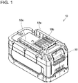
FIG. 1 is an oblique view that shows the external appearance of abattery pack 10 according to an exemplary embodiment of the present teachings. -
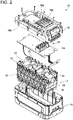
FIG. 2 is an exploded view of thebattery pack 10 according to the exemplary embodiment. -
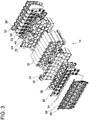
FIG. 3 is an exploded view of acell holder 14 according to the exemplary embodiment. -
FIG. 4 is a front view of the positional relationships among a plurality ofbattery cells 12, a plurality oflead plates circuit board 16 in the exemplary embodiment. -
FIG. 5 is a left view of the positional relationships among the plurality ofbattery cells 12, the plurality oflead plates circuit board 16 in the exemplary embodiment. -
FIG. 6 is a right view of the positional relationships among the plurality ofbattery cells 12. the plurality oflead plates circuit board 16 in the exemplary embodiment. -
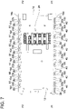
FIG. 7 is a plan view of the positional relationships among the plurality ofbattery cells 12, the plurality oflead plates circuit board 16 in the exemplary embodiment. -
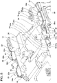
FIG. 8 is a partial, external, oblique view of thecell holder 14 according to the exemplary embodiment. -
FIG. 9 is an oblique view that shows the external appearance of a rear-surface side of thecircuit board 16 according to the exemplary embodiment. -
FIG. 10 is a cross-sectional view that shows an exemplary structure of a connection location, at which afirst terminal portion 20b (second terminal portion 22b) is connected to thecircuit board 16, in the exemplary embodiment. - Representative, non-limiting concrete examples of the present invention are described below in detail with reference to the drawings.
- The battery pack according to present invention as defined in claim 1, comprises housing; a battery cell or battery cells, which is (are) housed inside the housing; a seat surface or seat surfaces, which is (are) disposed inside the housing; a circuit board, which is housed inside the housing and is mounted on the seat surface(s); a terminal or terminals within the housing, which is (are) connected to the circuit board; an elastic sheet or elastic sheets, which surround(s) (encircle(s)) the perimeter(s) of the terminal(s) interposed between the circuit board and the seat surface(s) and furthermore notch(es) on specific places of the circuit board.
- According to the above-mentioned configuration, even if an electrically conductive substance, such as water, has adhered to (contacts) a surface of the circuit board on the side that makes contact with the seat surface(s), the connection location(s)-at which the circuit board and the terminal(s) are connected (electrically connected)-is (are) sealed by the elastic sheet(s), and therefore it is possible to prevent adverse short circuiting between any of the connection location(s), at which the circuit board and the terminal(s) are respectively connected (electrically connected), and one or more other locations. In addition, according to the above-mentioned configuration, the elastic sheet(s) is (are) interposed between the circuit board and the seat surface(s), and therefore the adhesion properties of the elastic sheet can be further improved.
- In one or more embodiments of the present teachings, the terminal(s) may be connected (electrically connected) to the battery cell(s).
- In the event that any connection location, at which the circuit board and the terminal(s) and the battery cell(s) are connected (electrically connected), were to (hypothetically) adversely short circuit with another electrically-conductive location, a large electrical current may flow and cause permanent damage to the battery cell(s) and/or the circuit board. Therefore, a technique for reliably preventing short circuits is desirable. According to the above-mentioned configuration, it is possible to reliably prevent any connection location(s), at which the circuit board and the terminal(s) connected to the battery cell(s) are connected, from adversely short circuiting with another location owing to the fact that the elastic sheet(s) surround(s) the terminal or each of the terminals. In a preferred embodiment, one or more through holes are formed in the elastic sheet(s) and the terminal(s) (respectively) pass(es) through the hole(s).
- In one or more embodiments of the present teachings, the battery pack may further comprise a cell holder, which is housed inside the housing and holds the battery cell(s). The seat surface(s) may be formed on the cell holder.
- By using a configuration in which the seat surface(s) is (are) formed on the cell holder, which holds the battery cell(s), and the circuit board is mounted on those seat surface(s), the battery pack can be made more compact. According to the above-mentioned configuration of the battery pack, it is possible to prevent any connection location, at which the circuit board and the terminal(s) are connected (electrically connected), from adversely short circuiting with another location.
- In one or more embodiments of the present teachings, the elastic sheet(s) may be bonded (glued, adhered) to the circuit board.
- According to the above-mentioned configuration, by mounting the circuit board on the seat surface(s) with the elastic sheet(s) bonded to the circuit board, the elastic sheet(s) can be interposed between the circuit board and the seat surface(s) without dislodging during operation. In addition, the elastic sheet(s) may be easily aligned with the connection location(s), at which the circuit board and the terminal(s) are connected. For example, in an embodiment in which holes are formed in the elastic sheet(s) for passing through the terminals, the holes of the elastic sheet(s) are aligned with corresponding through holes formed in the circuit board.
- The terminals comprise a first terminal, which is connected to the circuit board, and a second terminal, which is connected to the circuit board separately (spaced apart, discretely) from the first terminal. The shape(s) of the elastic sheet(s) is (are) preferably designed such that the elastic sheet(s) seamlessly and integrally surround(s) (encircle) the perimeters of both of the first terminal and the second terminal.
- According to the above-mentioned configuration, the connection location at which the circuit board and the first terminal are connected and the connection location at which the circuit board and the second terminal are connected can be protected by the single elastic sheet. Accordingly, the part count of the battery pack can be reduced.
- The circuit board has a notch between the connection location at which the first terminal and the circuit board are connected and the connection location at which the second terminal and the circuit board are connected. In embodiments in which three or more terminals are provided, one notch may be provided between each set of adjacent ones of the terminals, such that a plurality of notches may be provided in the circuit board, e.g., at regular intervals along one or both edges of the circuit board. The notch(es) is (are) preferably defined along an edge of the circuit board between adjacent connection locations such that a line intersecting the adjacent connection locations is intersected by the notch(es).
- According to the above-mentioned configuration, it is possible to more reliably prevent the occurrence of adverse short circuiting between the connection location at which the circuit board and the first terminal are connected and the connection location at which the circuit board and the second terminal are connected.
- In one or more embodiments of the present teachings, the battery pack may further comprise a (protective) coating or coatings, which is (are) provided on the surface of the circuit board on the side opposite the surface on which the elastic sheet(s) is (are) provided and cover(s) and/or seal(s) the connection location(s) at which the circuit board and the terminal(s) are connected.
- In the above-mentioned configuration, on one surface of the circuit board, the connection location(s)-at which the circuit board and the terminal(s) is (are) connected-is (are) protected by the elastic sheet(s). On the other (opposite side) surface of the circuit board, the connection location(s)-at which the circuit board and the terminal(s) is (are) connected-is (are) protected by the coating(s). Accordingly, it is possible to more reliably prevent the occurrence of short circuiting between any connection locations, at which the circuit board and the terminal(s) are connected, and another location.
- In one or more embodiments of the present teachings, the elastic sheet(s) may be composed of at least one material selected from the group consisting of rubber, elastomer, resin (polymer) foam, and sponge.
- According to the above-mentioned configuration, the elastic sheet(s) can be prepared from a material that is easy to obtain and easy to mold, and consequently the manufacturing cost of the battery pack can be reduced.
- A battery pack (battery cartridge) 10 according to one representative, non-limiting exemplary embodiment of the present teachings will now be explained, with reference to the drawings. The
battery pack 10 of the present exemplary embodiment is a rechargeable power storage device that serves as a power supply for supplying electric power to an electrical device (not shown) such as a power tool, e.g., hammer driver-drills, circular saws, chain saws, lawn mowers, blowers, etc.. and is mountable on and demountable (removable) from the electrical device. As shown inFIGS. I and2 , thebattery pack 10 comprises: a plurality ofbattery cells 12; a cell holder (battery cell holder) 14. which holds the plurality ofbattery cells 12; and acircuit board 16, which is fixed to thecell holder 14 and is electrically connected to the plurality ofbattery cells 12. In addition, thebattery pack 10 comprises ahousing 18, which houses the plurality ofbattery cells 12, thecell holder 14, and thecircuit board 16. - The
battery cells 12 are held by thecell holder 14 such that thebattery cells 12 are parallel to one another. Each of thebattery cells 12 is a rechargeable battery cell. Although just one example of the present teachings, each of thebattery cells 12 in the present exemplary embodiment may be, e.g., a lithium-ion battery cell having a nominal voltage of approximately 4 volts. In addition, with regard to the number ofbattery cells 12, thirty-two of thebattery cells 12 may be arranged (electrically connected) such one set of battery cells consists of twobattery cells 12 connected to one another in parallel and sixteen sets of such parallel-connectedbattery cells 12 are connected in series. In this arrangement, thebattery pack 10 has a nominal voltage of approximately 64 volts. - The
cell holder 14 is composed of an electrically-insulating material (e.g., a resin (synthetic) material, preferably a hard or rigid polymer material). A plurality of first lead plates (battery connection terminals) 20 and a plurality of second lead plates (battery connection terminals) 22 are incorporated in thecell holder 14. More specifically, thefirst lead plates 20 are disposed on one sidewall of thecell holder 14, and thesecond lead plates 22 are disposed on the other (opposite) sidewall of thecell holder 14. Thebattery cells 12 are electrically connected to one another by thefirst lead plates 20 and thesecond lead plates 22. In addition, each of thefirst lead plates 20 and each of thesecond lead plates 22 are electrically connected to thecircuit board 16. Thecircuit board 16 has wiring or busbars that electrically connect(s) thefirst lead plates 20 and thesecond lead plates 22 in series, thereby creating the 64 volt power supply. - In the present specification, the term "lead plate" is used in a manner that is synonymous with "connection tabs" or "connection strips". It is noted that the term "lead" is being used in the sense of an "electrical lead" and not in the sense of the element lead (Pb). Thus, lead plates may be made of any conductive metal or alloy, such as copper, copper alloy, aluminum, aluminum alloy, etc.
- Thus, the
circuit board 16 is electrically connected to the plurality ofbattery cells 12 via thefirst lead plates 20 and thesecond lead plates 22. Thecircuit board 16 is configured/adapted to detect the voltages of each of thefirst lead plates 20 and the voltages of each of thesecond lead plates 22 and thereby can ascertain the voltage of each of thebattery cells 12, in order to diagnose whether one or more of thebattery cells 12 is undercharged and/or permanently damaged. In addition, a plurality of external-connection terminals 24 is provided on thecircuit board 16. The external-connection terminals 24 are designed to be connected with the electrical device and may include, e.g., a pair of electric-power (plus and minus battery) terminals and one or more signal/data communication terminals. The pair of electric-power terminals is electrically connected to thebattery cells 12 and outputs, to the electrical device, electrical power (current) discharged (supplied) from thebattery cells 12. In addition, the pair of electric-power terminals is configured to be electrically connected to a charger (not shown) to receive charging current supplied from the charger for recharging thebattery cells 12. The signal/data communication terminal(s) is (are) connected to a processor (not shown) provided on thecircuit board 16. The processor (e.g., a microprocessor and memory) may execute programs for determining and outputting one or more signals indicative of. e.g., the current voltage of thebattery pack 10, the remaining battery capacity of thebattery pack 10, the temperature within thebattery pack 10, etc. - The outer shape of the
housing 18 is substantially rectangular parallelepiped. Thehousing 18 is preferably formed from a resin (synthetic) material, such as a hard or rigid polymer material. Engaging structures (e.g., rails) 18a for engaging with the electrical device and a plurality ofopenings 18b (e.g., slits), which receive corresponding connection terminals of the electrical device, are formed on an upper surface of thehousing 18. The external-connection terminals 24 on thecircuit board 16 are respectively disposed (extend) inside the plurality ofopenings 18b. It is noted that the configuration of thehousing 18 explained herein is but one example, and the specific configuration of thehousing 18 can be modified where appropriate. - Next, the structure of the
cell holder 14 will be explained, with reference toFIG. 3 . Thecell holder 14 comprises a first holdermain body 26 and a second holdermain body 28. The first holdermain body 26 and the second holdermain body 28 are fixed to one another while sandwiching the plurality ofbattery cells 12 therebetween, thereby holding (retaining) the plurality ofbattery cells 12 such that thebattery cells 12 are parallel to one another. Thecell holder 14 further comprises afirst holder cover 30 and asecond holder cover 32. Thefirst holder cover 30 sandwiches (covers) the plurality offirst lead plates 20 and is mounted on (affixed to) the first holdermain body 26, thereby fixing the plurality offirst lead plates 20 to the first holder main body 26 (i.e., to the plurality of battery cells 12). Thesecond holder cover 32 sandwiches (covers) the plurality ofsecond lead plates 22 and is mounted on the second holdermain body 28, thereby fixing the plurality ofsecond lead plates 22 to the second holder main body 28 (i.e., to the plurality of battery cells 12). - A first outer-side
waterproof sheet 34 is provided (interposed) between thefirst holder cover 30 and the plurality offirst lead plates 20. and a first inner-sidewaterproof sheet 36 is provided (interposed) between the plurality offirst lead plates 20 and the first holdermain body 26. The first outer-sidewaterproof sheet 34 and the first inner-sidewaterproof sheet 36 are composed of silicone rubber and prohibit (block) the ingress of moisture, minute foreign matter, and the like. In other words, thefirst lead plates 20 are integrally held between a pair of waterproof films (34, 36) by virtue of being laminated therebetween. Similarly, a second outer-sidewaterproof sheet 38 is provided (interposed) between thesecond holder cover 32 and the plurality ofsecond lead plates 22, and a second inner-sidewaterproof sheet 40 is provided (interposed) between the plurality ofsecond lead plates 22 and the second holdermain body 28. The second outer-sidewaterproof sheet 38 and the second inner-sidewaterproof sheet 40 are also composed of silicone rubber and prohibit the ingress of moisture, minute foreign matter, and the like. Thus, thesecond lead plates 22 are also integrally held between a pair of waterproof films (38, 40) by virtue of being laminated therebetween. - It is noted that each of the
waterproof sheets waterproof sheets waterproof sheets - Next, the structures of the
first lead plates 20 and thesecond lead plates 22 will be explained further in detail. It is noted that thecell holder 14 is not shown inFIG. 4 to FIG. 6 for the sake of simplicity. As shown inFIG. 4 to FIG. 6 , thefirst lead plates 20 are arrayed (arranged, disposed) along (within) a first plane P1, and thesecond lead plates 22 are arrayed (arranged, disposed) along (within) a second plane P2 that is preferably parallel or at least substantially parallel (e.g., less than an angle of 5°) with the first plane P1. Furthermore, each of thebattery cells 12 comprises afirst end 12a, which faces the first plane P1, and asecond end 12b, which faces the second plane P2 parallel to the first plane P1. It is noted that the orientations of thebattery cells 12 are not all the same. That is, some of thebattery cells 12 have their positive electrodes on (at) the first ends 12a and their negative electrodes on (at) the second ends 12b, while theother battery cells 12 have their negative electrodes on (at) the first ends 12a and their positive electrodes on (at) the second ends 12b. - Each of the
first lead plates 20 comprises: a first main portion (strip) 20a, which is located along (extends within) the first plane P1; a first terminal portion (tab) 20b, which passes through a hole (described below) in, and is electrically connected to, thecircuit board 16 in the vicinity of afirst side edge 16a of thecircuit board 16; and a first extension (bent)portion 20c, which connects the firstmain portion 20a to the firstterminal portion 20b. The firstmain portions 20a are respectively connected to one or more of the first ends 12a (i.e., the positive electrode or the negative electrode) of thebattery cells 12. Although not particularly limited, in the present exemplary embodiment, the firstmain portions 20a are joined (electrically connected) to the first end(s) 12a of one or more of thebattery cells 12 by spot welding (electrical resistance welding). A plurality of first throughholes 16c (seeFIGS. 7 ,9 , and10 ) is formed, corresponding to the plurality of firstterminal portions 20b, in thecircuit board 16. Thus, the firstterminal portions 20b respectively pass through, from a rear-surface side to a front-surface side, thecircuit board 16 via the corresponding first throughholes 16c and are joined (electrically connected) to thecircuit board 16 by soldering. - Likewise, each of the
second lead plates 22 comprises: a second main portion (strip) 22a, which is located along (extends within) the second plane P2; a second terminal portion (tab) 22b, which passes through a hole (described below) in, and is electrically connected to, thecircuit board 16 in the vicinity of asecond side edge 16b of thecircuit board 16; and a second extension (bent)portion 22c, which connects the secondmain portion 22a to the secondterminal portion 22b. The secondmain portions 22a are respectively connected to one or more of the second ends 12b (i.e., the positive electrode or the negative electrode) of thebattery cells 12. Although not particularly limited, in the present exemplary embodiment, the secondmain portions 22a are joined (electrically connected) to the second end(s) 12b of one or more of thebattery cells 12 by spot welding (resistance welding). A plurality of second throughholes 16d seeFIGS. 7 ,9 , and10 ) is formed, corresponding to the plurality of secondterminal portions 22b, in thecircuit board 16. Thus, the secondterminal portions 22b respectively pass through, from the rear-surface side to the front-surface side, thecircuit board 16 via the corresponding second throughholes 16d and are joined (electrically connected) to thecircuit board 16 by soldering. - As shown in
FIG. 7 , the front-surface side of thecircuit board 16 is coated withcoatings 50 that respectively cover the connection locations at which the firstterminal portions 20b are connected to thecircuit board 16 and the connection locations at which the secondterminal portions 22b are connected to thecircuit board 16. Thecoatings 50 are composed of, for example, urethane resin (polyurethane), epoxy resin, polyurea, or the like. Therefore, even if an electrically conductive substance, such as water, has adhered to (contacts) the front-surface side of thecircuit board 16, thecoatings 50 can prevent the firstterminal portions 20b and the secondterminal portions 22b from adversely short circuiting with their adjacent firstterminal portions 20b and secondterminal portions 22b, respectively. Therefore, thecoatings 50 are preferably a durable, tough, electrically-insulating material that encapsulates the first and secondterminal portions coatings 50 are also preferably hard. In the present embodiment, a plurality of discrete (non-continuous)coatings 50 is provided, but it is also possible to apply the coating material such that two or more of the connection locations (first and/or secondterminal portions coating 50. - As shown in
FIGS. 4 and7 , thecircuit board 16 extends from thefirst side edge 16a to the second side edge 16b. which is located on the side opposite thefirst side edge 16a, such that thecircuit board 16 intersects (and is preferably perpendicular to) the first plane P1 and the second plane P2. That is, thecircuit board 16 according to the present exemplary embodiment is comparatively large, and its width from thefirst side edge 16a to thesecond side edge 16b is greater than the length of thebattery cells 12. - As shown in
FIG. 7 , in thebattery pack 10 according to the present exemplary embodiment, a plurality offirst notches 42 is provided on (in) thefirst side edge 16a of thecircuit board 16. Each of thefirst notches 42 extends (is disposed) between two adjacent firstterminal portions 20b in the direction of the first plane P1. Owing to such a configuration (arrangement) of thenotches 42 and the locations of the firstterminal portions 20b, the electrical insulation properties between the firstterminal portions 20b on thecircuit board 16 can be improved, because there is no bridge-like material between adjacent firstterminal portions 20b in the direction of the first plane P1. In a similar manner, a plurality ofsecond notches 44 also is provided on thesecond side edge 16b of thecircuit board 16. Each of thesecond notches 44 extends (is disposed) between two adjacent secondterminal portions 22b in the direction of the second plane P2. Again, owing to such a configuration (arrangement) of thenotches 44 and the locations of the secondterminal portions 22b, the electrical insulation properties between the secondterminal portions 22b on thecircuit board 16 can be improved, because there is no bridge-like material between adjacent secondterminal portions 22b in the direction of the second plane P2. - As shown in
FIGS. 3 and8 . in thebattery pack 10 according to the present exemplary embodiment, a plurality of first support pieces (flanges, cantilevers) 52 is formed (arrayed, arranged), corresponding to the plurality offirst lead plates 20, on (along an edge of) the first holdermain body 26. As shown inFIG. 10 , when thecircuit board 16 has been mounted on thecell holder 14, each of thefirst support pieces 52 is interposed between thecircuit board 16 and the first extension (bent)portion 20c of the correspondingfirst lead plate 20. Likewise, a plurality of second support pieces (flanges, cantilevers) 54 is formed (arrayed, arranged), corresponding to the plurality ofsecond lead plates 22, on (along an edge of) the second holdermain body 28. When thecircuit board 16 has been mounted on thecell holder 14, each of thesecond support pieces 54 is interposed between thecircuit board 16 and the second extension (bent)portion 22c of the correspondingsecond lead plate 22. - As also shown in
FIGS. 3 and8 , in thebattery pack 10 according to the present exemplary embodiment, a plurality of first support platforms (bent flanges) 56 is formed, corresponding to the plurality offirst support pieces 52, on thefirst holder cover 30. Each of thefirst support platforms 56 is formed into (has) a shape that surrounds the perimeter of the correspondingfirst support piece 52 and the perimeter of thefirst extension portion 20c of the correspondingfirst lead plate 20. Likewise, a plurality of second support platforms (bent flanges) 58 is formed, corresponding to the plurality ofsecond support pieces 54, on thesecond holder cover 32. Each of thesecond support platforms 58 is formed into (has) a shape that surrounds the perimeter of the correspondingsecond support piece 54 and the perimeter of thesecond extension portion 22c of the correspondingsecond lead plate 22. - Each of the
first support pieces 52 has a first inner-side seat surface 52a, which opposes the rear surface of thecircuit board 16. Each of thesecond support pieces 54 has a second inner-side seat surface 54a, which opposes the rear surface of thecircuit board 16. Each of thefirst support platforms 56 has a first outer-side seat surface 56a, which opposes the rear surface of thecircuit board 16. Each of thesecond support platforms 58 has a second outer-side seat surface 58a, which opposes the rear surface of thecircuit board 16. When thecircuit board 16 is to be mounted on thecell holder 14, thecircuit board 16 is fixed by one or more screws (not shown) to thecell holder 14 with thecircuit board 16 mounted on the first inner-side seat surfaces 52a, the second inner-side seat surfaces 54a, the first outer-side seat surfaces 56a. and the second outer-side seat surfaces 58a. - As shown in
FIG. 9 , a first waterproof sheet (gasket) 60 and a second waterproof sheet (gasket) 62 are bonded (glued, adhered) to the rear surface of thecircuit board 16. The firstwaterproof sheet 60 may extend in parallel or substantially in parallel to secondwaterproof sheet 62. Furthermore, the first plane P1 intersects the firstwaterproof sheet 60 and the second plane P2 intersects the secondwaterproof sheet 62. The firstwaterproof sheet 60 and the secondwaterproof sheet 62 are composed of silicone rubber and prohibit (block) the ingress of moisture, minute foreign matter, and the like to the first and secondterminal portions circuit board 16 on the one side and thecell holder 14 on the other side. - The first
waterproof sheet 60 is a single (seamless, integral) sheet material that is bonded from one end part to the other end part of thecircuit board 16 in the longitudinal direction along thefirst side edge 16a. The firstwaterproof sheet 60 is formed into (has) a shape such that the perimeter of each of the first throughholes 16c of thecircuit board 16 is surrounded (encircled) in the direction perpendicular to the extension direction of the firstterminal portions 20b that respectively pass through the first throughholes 16c of thecircuit board 16. More specifically, a set of first throughholes 60a is defined in the firstwaterproof sheet 60 and these first throughholes 60a are respectively aligned with the first throughholes 16c of thecircuit board 16 in the extension direction of the firstterminal portions 20b. Consequently, when thecircuit board 16 has been mounted on thecell holder 14, the firstwaterproof sheet 60 is disposed such that the material of the firstwaterproof sheet 60 surrounds (encircles) the perimeters of all of the firstterminal portions 20b of the plurality offirst lead plates 20. Therefore, even if an electrically conductive substance, such as water, has adhered to (contacts) the rear-surface side of thecircuit board 16, the firstwaterproof sheet 60 blocks the ingress of such electrically conductive substance into the space around the perimeters of the firstterminal portions 20b, thereby preventing the firstterminal portions 20b from adversely short circuiting with each other (i.e. with adjacent firstterminal portions 20b). - Likewise, the second
waterproof sheet 62 is a single (seamless, integral) sheet material that is bonded from one end part to the other end part of thecircuit board 16 in the longitudinal direction along thesecond side edge 16b. The secondwaterproof sheet 62 is formed into (has) a shape such that that the perimeter of each of the second throughholes 16d of thecircuit board 16 is surrounded (encircled) in the direction perpendicular to the extension direction of the secondterminal portions 22b that respectively pass through the second throughholes 16d of thecircuit board 16. More specifically, a set of second throughholes 62a is defined in the secondwaterproof sheet 62 and these second throughholes 62a are respectively aligned with the second throughholes 16d of thecircuit board 16 in the extension direction of the secondterminal portions 22b. Consequently, when thecircuit board 16 has been mounted on thecell holder 14, the secondwaterproof sheet 62 is disposed such that the material of the secondwaterproof sheet 62 surrounds (encircles) the perimeters of all of the secondterminal portions 22b of the plurality ofsecond lead plates 22. Consequently, even if an electrically conductive substance, such as water, has adhered to (contacts) the rear-surface side of thecircuit board 16, the secondwaterproof sheet 62 blocks the ingress of such electrically conductive substance into the space around the perimeters of the secondterminal portions 22b, thereby preventing the secondterminal portions 22b from adversely short circuiting with each other (i.e. with adjacent secondterminal portions 22b). - It is noted that the first
waterproof sheet 60 and the secondwaterproof sheet 62 are not limited to being composed of silicone rubber. That is, one or both of the first andwaterproof sheets waterproof sheets cell holder 14 and thecircuit board 16 during operation. - The
waterproof sheets waterproof sheets waterproof sheets 60, 62 (and optionally thewaterproof sheets waterproof sheets 60, 62 (and optionally thewaterproof sheets waterproof sheets 60, 62 (and optionally thewaterproof sheets - The material of the first and second
waterproof sheets 60, 62 (and optionally thewaterproof sheets - The thickness of the first and second
waterproof sheets 60. 62 (and optionally thewaterproof sheets waterproof sheets 60, 62 (and optionally thewaterproof sheets waterproof sheets 60, 62 (and optionally thewaterproof sheets - As shown in
FIG. 10 , in thebattery pack 10 according to the present exemplary embodiment, when thecircuit board 16 has been mounted on thecell holder 14, the firstwaterproof sheet 60 is interposed between and pressed (compressed) by the first inner-side seat surfaces 52a and the rear surface of thecircuit board 16 and is also interposed between and pressed (compressed) by the first outer-side seat surfaces 56a and the rear surface of thecircuit board 16. Thereby, owing to the firstwaterproof sheet 60, the waterproofness of the first lead plates 20 (in particular, the firstterminal portions 20b thereof) can be further increased and improved electrical isolation (insulation) between the firstterminal portions 20b on thecircuit board 16 can be provided. Likewise, when thecircuit board 16 has been mounted on thecell holder 14, the secondwaterproof sheet 62 is interposed between and pressed (compressed) by the second inner-side seat surfaces 54a and the rear surface of thecircuit board 16 and is also interposed between and pressed (compressed) by the second outer-side seat surfaces 58a and the rear surface of thecircuit board 16. Thereby, owing to the secondwaterproof sheet 62, the waterproofness of the second lead plates 22 (in particular, the secondterminal portions 22b thereof) can be further increased and improved electrical isolation (insulation) between the secondterminal portions 22b on thecircuit board 16 can be provided. - It is noted that, although a configuration was explained in the above-described exemplary embodiment that prevents any of the connection locations at which the
circuit board 16 on one side and thefirst lead plates 20 and thesecond lead plates 22, which are connected to thebattery cells 12, on the other side are connected from short circuiting with another location, the same configuration may be applied between connection locations at which thecircuit board 16 and other terminals are connected and may be applied between connection locations at which another circuit board and other terminals are connected. - In the above- described exemplary embodiment, when the
circuit board 16 is viewed from the front-surface side (or the rear-surface side) in plan view, thefirst side edge 16a and thesecond side edge 16b each extend substantially rectilinearly. Furthermore, the plurality of first throughholes 16c and the plurality of second throughholes 16d are disposed rectilinearly along thefirst side edge 16a and thesecond side edge 16b, respectively. Consequently, the connection locations-at which thecircuit board 16 and the plurality of firstterminal portions 20b are respectively connected-are disposed rectilinearly along thefirst side edge 16a, and the firstwaterproof sheet 60 has a substantially oblong (elongated) shape with throughholes 60a corresponding to the connection locations at which thecircuit board 16 and the plurality of firstterminal portions 20b are respectively connected. Likewise, the connection locations-at which thecircuit board 16 and the plurality of firstterminal portions 20b are respectively connected-are disposed rectilinearly along thesecond side edge 16b, and the secondwaterproof sheet 62 has a substantially oblong (elongated) shape with throughholes 62a corresponding to the connection locations at which thecircuit board 16 and the plurality of secondterminal portions 22b are connected. - However, when the
circuit board 16 is viewed from the front-surface side (or the rear-surface side) in plan view, in alternate embodiments of the present teachings, thefirst side edge 16a and thesecond side edge 16b do not have to be rectilinear, and the plurality of first throughholes 16c and the plurality of second throughholes 16d do not have to be disposed rectilinearly. In addition, the firstwaterproof sheet 60 may be formed into (may have) any shape as long as the material of the firstwaterproof sheet 60 surrounds (encircles) the perimeter of every connection location at which thecircuit board 16 and the plurality of firstterminal portions 20b are respectively connected. Similarly, the secondwaterproof sheet 62 may be formed into (may have) any shape as long as the material of the secondwaterproof sheet 62 surrounds (encircles) the perimeter of every connection location at which thecircuit board 16 and the plurality of secondterminal portions 22b are respectively connected. - For example, if one or more screw-fastening parts (not shown), which is (are) for fixing the
circuit board 16 to thecell holder 14 using one or more screws, is (are) provided in the vicinity of the connection locations at which thecircuit board 16 and the plurality of firstterminal portions 20b are respectively connected, in the vicinity of the connection locations at which thecircuit board 16 and the plurality of secondterminal portions 22b are respectively connected, or the like, then the firstwaterproof sheet 60, the secondwaterproof sheet 62, or the like may be formed into (may have) a shape that circumvents (goes around) the vicinity of the screw-fastening part(s). In addition or in the alternative, if a drain hole (not shown) is formed in thecircuit board 16 in the vicinity of the connection locations at which thecircuit board 16 and the plurality of firstterminal portions 20b are respectively connected, in the vicinity of the connection locations at which thecircuit board 16 and the plurality of secondterminal portions 22b are respectively connected, or the like, then the firstwaterproof sheet 60, the secondwaterproof sheet 62. or the like may be formed into a shape that circumvents (goes around) the vicinity of the drain hole. - As described above, in one or more embodiments of the present teachings, the battery pack 10 may optionally comprise: the housing 18; the battery cells 12, which are housed inside the housing 18; the first inner-side seat surfaces 52a and the first outer-side seat surfaces 56a (and optionally the second inner-side seat surfaces 54a and the second outer-side seat surfaces 58a) (representative, non-limiting examples of a "seat surface" according to the present teachings) disposed inside the housing 18; the circuit board 16 (representative, non-limiting example of a "circuit board" according to the present teachings), which is housed inside the housing 18 and is mounted on the first inner-side seat surfaces 52a and the first outer-side seat surfaces 56a (and optionally the second inner-side seat surfaces 54a and the second outer-side seat surfaces 58a); the first terminal portions 20b (and optionally the second terminal portions 22b) (representative, non-limiting examples of a "terminal" according to the present teachings) within the housing 18, which are connected to the circuit board 16; and the first waterproof sheet 60 (and optionally the second waterproof sheet 62) (representative, non-limiting example of an "elastic sheet" according to the present teachings), which surrounds the perimeters of the first terminal portions 20b (and optionally the second terminal portions 22b) and is interposed between the circuit board 16 on one side and the first inner-side seat surfaces 52a and the first outer-side seat surfaces 56a on the other side (and optionally the second inner-side seat surfaces 54a and the second outer-side seat surfaces 58a on the other side).
- According to the above-mentioned configuration, even if an electrically conductive substance, such as water, has adhered to (contacts) a surface of the
circuit board 16 on the side that makes contact with the first inner-side seat surfaces 52a and the first outer-side seat surfaces 56a (and optionally the second inner-side seat surfaces 54a and the second outer-side seat surfaces 58a), the connection locations-at which thecircuit board 16 and the firstterminal portions 20b (and optionally the secondterminal portions 22b) are respectively connected-are sealed by the first waterproof sheet 60 (and optionally the second waterproof sheet 62). Therefore, this configuration prevents the possibility of adverse short circuiting between any of the connection locations at which thecircuit board 16 and the firstterminal portions 20b (and the secondterminal portions 22b) are respectively connected and another location that should not be electrically connected thereto. In addition, according to the above-mentioned configuration, the first waterproof sheet 60 (and optionally the second waterproof sheet 62) is interposed between thecircuit board 16 on one side and the first inner-side seat surfaces 52a and the first outer-side seat surfaces 56a on the other side (and optionally the second inner-side seat surfaces 54a and the second outer-side seat surfaces 58a on the other side). Therefore, the adhesion characteristics of the first waterproof sheet 60 (and optionally the second waterproof sheet 62) can be further improved. - In one or more embodiments of the present teachings, the first
terminal portions 20b (and optionally the secondterminal portions 22b) are connected (electrically connected) to thebattery cells 12. - In such embodiments, in the event that any of the connection locations, at which the
circuit board 16 and the firstterminal portions 20b (and the secondterminal portions 22b) connected to thebattery cells 12 are respectively connected, were to (hypothetically) adversely short circuit (become electrically connected) with another location (i.e. to which the connection location should not be electrically connected), a large electrical current may flow and might damage thebattery cells 12 and/or thecircuit board 16, Therefore it is necessary to reliably prevent short circuits between thebattery cells 12. According to the above-mentioned configuration, it is possible to reliably prevent any of the connection locations, at which thecircuit board 16 and the firstterminal portions 20b (and the secondterminal portions 22b) connected to thebattery cells 12 are respectively connected, from adversely short circuiting with another location, to which the connection locations should not be electrically connected. - In one or more embodiments of the present teachings, the
battery pack 10 may optionally further comprise thecell holder 14, which is housed inside thehousing 18 and holds thebattery cells 12. The first inner-side seat surfaces 52a and the first outer-side seat surfaces 56a (and optionally the second inner-side seat surfaces 54a and the second outer-side seat surfaces 58a) may be formed on thecell holder 14. - By using a configuration such that the first inner-side seat surfaces 52a and the first outer-
side seat surfaces 56a (and the second inner-side seat surfaces 54a and the second outer-side seat surfaces 58a) are formed on thecell holder 14, which holds thebattery cells 12, and such that thecircuit board 16 is mounted on the first inner-side seat surfaces 52a and the first outer-side seat surfaces 56a (and the second inner-side seat surfaces 54a and the second outer-side seat surfaces 58a), thebattery pack 10 can be made more compact. According to the above-mentioned configuration, such abattery pack 10 makes it possible to prevent any of the connection locations, at which thecircuit board 16 and the firstterminal portions 20b (and the secondterminal portions 22b) are respectively connected, from adversely short circuiting with another location, to which the connection locations should not be electrically connected. - In one or more embodiments of the present teachings, the first waterproof sheet 60 (and optionally the second waterproof sheet 62) is bonded (adhered) to the
circuit board 16. - According to the above-mentioned configuration, the
circuit board 16 is mounted on the first inner-side seat surfaces 52a and the first outer-side seat surfaces 56a (and optionally the second inner-side seat surfaces 54a and the second outer-side seat surfaces 58a) with the first waterproof sheet 60 (and optionally the second waterproof sheet 62) bonded to thecircuit board 16. Therefore, the first waterproof sheet 60 (and optionally the second waterproof sheet 62) can be interposed between thecircuit board 16 on one side and the first inner-side seat surfaces 52a and the first outer-side seat surfaces 56a on the other side (and optionally the second inner-side seat surfaces 54a and the second outer-side seat surfaces 58a on the other side). Consequently, the first waterproof sheet 60 (and optionally the second waterproof sheet 62) can be easily aligned with the connection locations, at which thecircuit board 16 and the firstterminal portions 20b (and the secondterminal portions 22b) are respectively connected. - In one or more embodiments of the present teachings, a plurality of first
terminal portions 20b (and optionally secondterminal portions 22b) (representative, non-limiting examples of a "first terminal" and a "second terminal" according to the present teaching) may be provided, and each is separately connected to thecircuit board 16. The first waterproof sheet 60 (and the second waterproof sheet 62) preferably has a shape such that the perimeters of the plurality of firstterminal portions 20b (and secondterminal portions 22b) are seamlessly and integrally surrounded (encircled). - According to the above-mentioned configuration, every connection location, at which the
circuit board 16 and the plurality of firstterminal portions 20b are respectively connected, can be protected by a single waterproof sheet. Similarly, every connection location, at which thecircuit board 16 and the plurality of secondterminal portions 20b are respectively connected, can be protected by a single waterproof sheet. Accordingly, the part count of thebattery pack 10 can be reduced. - In one or more embodiments of the present teachings, the first notches 42 (and optionally second notches 44) (representative, non-limiting examples of a "notch" according to the present teachings) may be defined along an edge (or edges) of the
circuit board 16 between the connection locations, at which thecircuit board 16 and the plurality of firstterminal portions 20b (and optionally secondterminal portions 22b) are respectively connected. - According to the above-mentioned configuration, it is possible to more reliably prevent the occurrence of adverse short circuiting between the connection locations, at which the
circuit board 16 and the plurality of firstterminal portions 20b (and optionally secondterminal portions 22b) are connected. - In one or more embodiments of the present teachings, the
battery pack 10 may further comprise thecoatings 50 disposed on the surface of thecircuit board 16 on the side opposite the surface on which the first waterproof sheet 60 (and optionally the second waterproof sheet 62) is provided. Thesecoatings 50 may cover (seal) the connection locations at which thecircuit board 16 and the firstterminal portions 20b (and optionally the secondterminal portions 22b) are respectively connected. - In the above-mentioned configuration, on one surface of the
circuit board 16, the connection locations-at which thecircuit board 16 and the firstterminal portions 20b (and the secondterminal portions 22b) are respectively connected-are protected by the first waterproof sheet 60 (and the second waterproof sheet 62). On the other surface of thecircuit board 16, the connection locations-at which thecircuit board 16 and the firstterminal portions 20b (and the secondterminal portions 22b) are respectively connected-are protected by thecoatings 50. Accordingly, it is possible to more reliably prevent the occurrence of short circuiting between any of the connection locations, at which thecircuit board 16 and the firstterminal portions 20b (and optionally the secondterminal portions 22b) are connected, and another location that should not be electrically connected thereto. - In one or more embodiments of the present teachings, the first waterproof sheet 60 (and the second waterproof sheet 62) may be composed of at least one elastic (compressible) material selected from the group consisting of rubber, elastomer, resin foam, and sponge.
- According to the above-mentioned configuration, the first waterproof sheet 60 (and the second waterproof sheet 62) can be prepared from a material that is easy to obtain and easy to mold, and consequently the manufacturing cost of the
battery pack 10 can be reduced. -
- 10
- Battery pack
- 12
- Battery cell
- 12a
- First end
- 12b
- Second end
- 14
- Cell holder
- 16
- Circuit board
- 16a
- First side edge
- 16b
- Second side edge
- 16c
- First through hole
- 16d
- Second through hole
- 18
- Housing
- 18a
- Engaging structure
- 18b
- Opening
- 20
- First lead plate
- 20a
- First main portion
- 20b
- First terminal portion
- 20c
- First extension portion
- 22
- Second lead plate
- 22a
- Second main portion
- 22b
- Second terminal portion
- 22c
- Second extension portion
- 24
- External-connection terminal
- 26
- First holder main body
- 28
- Second holder main body
- 30
- First holder cover
- 32
- Second holder cover
- 34
- First outer-side waterproof sheet
- 36
- First inner-side waterproof sheet
- 38
- Second outer-side waterproof sheet
- 40
- Second inner-side waterproof sheet
- 42
- First notch
- 44
- Second notch
- 50
- Coating
- 52
- First support piece
- 52a
- First inner-side seat surface
- 54
- Second support piece
- 54a
- Second inner-side seat surface
- 56
- First support platform
- 56a
- First outer-side seat surface
- 58
- Second support platform
- 58a
- Second outer-side seat surface
- 60
- First waterproof sheet
- 62
- Second waterproof sheet
Claims (14)
- A battery pack (10) comprisinga housing (18),one or more battery cells (12) housed inside the housing,one or more seat surfaces (52a, 54a, 56a, 58a) disposed inside the housing,a circuit board (16), which is housed inside the housing and is mounted on the one or more seat surfaces,one or more terminals (20b, 22b) electrically connected to the circuit board and being disposed within the housing, andone or more elastic sheets (60, 62) surrounding the perimeter(s) of the terminal(s) and being interposed between the circuit board and the one or more seat surfaces,wherein the terminals (20, 22) comprise a first terminal (20b, 22b), which is connected to the circuit board (16), and a second terminal (20b, 22b), which is connected to the circuit board separately from the first terminal,characterized in thatthe circuit board (16) has a notch (42, 44) between the connection location at which the first terminal (20, 22) and the circuit board are connected and the connection location at which the second terminal (20, 22) and the circuit board are connected.
- The battery pack (10) according to claim 1, wherein the one or more terminals (20, 22) is (are) electrically connected to the one or more battery cells (12).
- The battery pack (10) according to claim 1 or 2, further comprising:a cell holder (14), which is housed inside the housing (18) and holds the one or more battery cells (12);wherein the one or more seat surfaces (52a, 54a, 56a, 58a) is (are) formed on the cell holder.
- The battery pack (10) according to any one of claims 1-3, wherein the one or more elastic sheets (60, 62) is (are) bonded to the circuit board (16).
- The battery pack (10) according to any one of claims 1-4, wherein the one or more elastic sheets (60, 62) is a single elastic sheet having a shape that seamlessly and integrally surrounds the perimeters of both of the first terminal and the second terminal.
- The battery pack (10) according to any one of claims 1-5, further comprisingone or more coatings (50) provided on a first surface of the circuit board (16) that is opposite a second surface of the circuit board on which the elastic sheet(s) (60, 62) is (are) provided,wherein the coating(s) cover(s) the connection location(s) at which the circuit board and the terminal(s) (20, 22) are connected.
- The battery pack (10) according to any one of claims 1-6, wherein the elastic sheet(s) (60, 62) is (are) composed of at least one material selected from the group consisting of rubber, elastomer, resin foam, and sponge.
- The battery pack (10) according to any one of claims 1-7, wherein the elastic sheet(s) (60, 62) exhibit(s) a compressibility in a thickness direction of the elastic sheet(s) of at least 3%.
- The battery pack (10) according to any one of claims 1-8, wherein the elastic sheet(s) (60, 62) exhibit(s) a recovery after compression in the thickness direction of the elastic sheet(s) of at least 40%.
- The battery pack (10) according to any one of claims 1-9, wherein the elastic sheet(s) (60, 62) has (have) a thickness of 0.3-4 mm.
- The battery pack (10) according to any one of claims 1-10, whereinthe elastic sheet(s) (60, 62) comprise a first elastic sheet (60) and a second elastic sheet (62),the terminal(s) (20b, 22b) comprise a plurality of first terminal portions (20b) and a plurality of second terminal portions (22b),the first elastic sheet (60) has a plurality of first through holes (60a), through which the first terminal portions (20b) respectively pass, andthe second elastic sheet (62) has a plurality of second through holes (62a), through which the second terminal portions (22b) respectively pass.
- The battery pack (10) according to claim 11, whereinthe first terminal portions (20b) are each respectively electrically connected to first ends (12a) of the battery cells (12) via a first main portion (20a) and a first bent extension portion (20c);the second terminal portions (22b) are respectively electrically connected to second ends (12b) of the battery cells (12) via a second main portion (22a) and a second bent extension portion (22c).
- The battery pack (10) according to claim 12, further comprisinga first waterproof sheet (36) covering the first main portions (20a), anda second waterproof sheet (38) covering the second main portions (22a).
- The battery pack (10) according to any one of claims 1-13, wherein engaging structures (18a) for engaging a power tool and external-connection terminals (24) for electrically connecting with the power tool are disposed on an outer surface of the housing (18).
Applications Claiming Priority (1)
| Application Number | Priority Date | Filing Date | Title |
|---|---|---|---|
| JP2019072933A JP2020170683A (en) | 2019-04-05 | 2019-04-05 | Battery pack |
Publications (2)
| Publication Number | Publication Date |
|---|---|
| EP3719860A1 EP3719860A1 (en) | 2020-10-07 |
| EP3719860B1 true EP3719860B1 (en) | 2022-11-16 |
Family
ID=69804716
Family Applications (1)
| Application Number | Title | Priority Date | Filing Date |
|---|---|---|---|
| EP20162501.9A Active EP3719860B1 (en) | 2019-04-05 | 2020-03-11 | Battery pack |
Country Status (4)
| Country | Link |
|---|---|
| US (1) | US11677116B2 (en) |
| EP (1) | EP3719860B1 (en) |
| JP (1) | JP2020170683A (en) |
| CN (1) | CN111799425B (en) |
Families Citing this family (19)
| Publication number | Priority date | Publication date | Assignee | Title |
|---|---|---|---|---|
| TWD200631S (en) * | 2017-01-17 | 2019-11-01 | Tti Macao Commercial Offshore Ltd | Battery pack |
| USD988984S1 (en) * | 2017-11-30 | 2023-06-13 | Walmart Apollo, Llc | Battery pack |
| CA189202S (en) | 2017-07-26 | 2020-10-09 | Walmart Apollo Llc | Battery pack |
| USD958061S1 (en) | 2017-07-26 | 2022-07-19 | Walmart Apollo, Llc | Battery pack |
| USD981950S1 (en) * | 2019-02-27 | 2023-03-28 | Techtronic Floor Care Technology Limited | Battery |
| USD950483S1 (en) * | 2019-08-01 | 2022-05-03 | Ridge Tool Company | Battery |
| USD959363S1 (en) * | 2019-08-05 | 2022-08-02 | Ridge Tool Company | Battery |
| USD987555S1 (en) * | 2019-11-13 | 2023-05-30 | Nanjing Chervon Industry Co., Ltd. | Battery pack |
| JP7789013B2 (en) * | 2020-12-07 | 2025-12-19 | 株式会社マキタ | Battery pack |
| JP7665367B2 (en) | 2021-03-23 | 2025-04-21 | 株式会社マキタ | Battery pack |
| CN114188644A (en) * | 2021-11-16 | 2022-03-15 | 深圳市海洋王照明工程有限公司 | Battery holder and battery module |
| US20240162575A1 (en) * | 2022-11-16 | 2024-05-16 | Milwaukee Electric Tool Corporation | Electric device with plastic molded thereon |
| CN118596090A (en) * | 2023-03-06 | 2024-09-06 | 南京泉峰科技有限公司 | Power tools and battery packs |
| EP4429003A1 (en) * | 2023-03-06 | 2024-09-11 | Nanjing Chervon Industry Co., Ltd. | Power tool and battery pack |
| CN119069908A (en) * | 2023-05-31 | 2024-12-03 | 南京泉峰科技有限公司 | Power tools and battery packs |
| CN117060146A (en) * | 2023-08-30 | 2023-11-14 | 上海拜骋电器有限公司 | Waterproof structure of battery pack connector and battery pack |
| DE202025103143U1 (en) * | 2025-02-28 | 2025-07-18 | Lawnix Technology (Nanjing) Co., Ltd | Tool battery pack |
| USD1122188S1 (en) * | 2025-04-18 | 2026-04-14 | Shenzhen Jinjunye Electronics Co., Ltd. | Power tool battery |
| USD1122189S1 (en) * | 2025-05-12 | 2026-04-14 | Shenzhen Jinjunye Electronics Co., Ltd. | Power tool battery |
Family Cites Families (35)
| Publication number | Priority date | Publication date | Assignee | Title |
|---|---|---|---|---|
| JPS60179675U (en) * | 1984-05-10 | 1985-11-29 | 大坪 英幸 | Paper outlet structure of tissue paper storage container |
| JP4524087B2 (en) * | 2003-10-10 | 2010-08-11 | 株式会社堀場製作所 | Absorption analyzer |
| US6972544B2 (en) | 2003-10-14 | 2005-12-06 | Black & Decker Inc. | Apparatus for interconnecting battery cells in a battery pack and method thereof |
| JP4578147B2 (en) | 2004-04-30 | 2010-11-10 | 三洋電機株式会社 | Pack battery |
| US7176656B2 (en) | 2004-06-22 | 2007-02-13 | Campbell Hausfeld/Scott Fetzer Company | Tool with battery pack |
| JP4568067B2 (en) | 2004-09-30 | 2010-10-27 | 三洋電機株式会社 | Pack battery |
| JP4530784B2 (en) | 2004-09-30 | 2010-08-25 | 三洋電機株式会社 | Pack battery |
| JP5284053B2 (en) * | 2008-11-17 | 2013-09-11 | 株式会社東芝 | Secondary battery pack |
| JP5451211B2 (en) | 2009-06-26 | 2014-03-26 | パナソニック株式会社 | Power storage unit |
| JP2011154986A (en) * | 2010-01-28 | 2011-08-11 | Sanyo Electric Co Ltd | Battery pack |
| JP2011171125A (en) | 2010-02-18 | 2011-09-01 | Sanyo Electric Co Ltd | Battery pack and method for manufacturing the same |
| US8815439B2 (en) * | 2010-04-13 | 2014-08-26 | Samsung Sdi Co., Ltd. | Secondary battery pack |
| US20120045665A1 (en) | 2010-08-17 | 2012-02-23 | Samsung Sdi Co., Ltd. | Battery pack |
| JP5592194B2 (en) | 2010-08-20 | 2014-09-17 | 三洋電機株式会社 | Battery pack |
| EP2637233B1 (en) | 2010-11-04 | 2017-09-06 | Makita Corporation | Battery pack |
| TWI424602B (en) * | 2010-12-03 | 2014-01-21 | Askey Computer Corp | Waterproof battery |
| US8968893B2 (en) | 2011-03-11 | 2015-03-03 | Samsung Sdi Co., Ltd. | Secondary battery |
| CN204424329U (en) * | 2011-12-30 | 2015-06-24 | 株式会社牧田 | Battery packs suitable for use with hand-held power tools |
| JP5037740B1 (en) | 2012-05-29 | 2012-10-03 | 日立マクセルエナジー株式会社 | Battery case and battery pack including the same |
| CN205177900U (en) * | 2012-06-12 | 2016-04-20 | 米沃奇电动工具公司 | Battery pack |
| KR20140010633A (en) | 2012-07-16 | 2014-01-27 | 삼성에스디아이 주식회사 | Battery pack |
| US20140178715A1 (en) * | 2012-12-21 | 2014-06-26 | Samsung Sdi Co., Ltd. | Battery pack |
| TWI462375B (en) | 2013-02-08 | 2014-11-21 | Simplo Technology Co Ltd | Battery module having a structure for coupling a circuit board and battery devices |
| JP2014197515A (en) * | 2013-03-29 | 2014-10-16 | 日立工機株式会社 | Battery pack and electric apparatus |
| JP6116974B2 (en) * | 2013-04-05 | 2017-04-19 | 株式会社マキタ | Battery pack for electric tools |
| US9318729B2 (en) * | 2013-04-05 | 2016-04-19 | Makita Corporation | Power tool battery pack |
| JP6284709B2 (en) * | 2013-04-05 | 2018-02-28 | 株式会社マキタ | Battery pack for electric tools |
| EP2811542B1 (en) | 2013-06-04 | 2018-07-25 | Samsung SDI Co., Ltd. | Battery pack |
| JP6587089B2 (en) * | 2015-01-30 | 2019-10-09 | パナソニックIpマネジメント株式会社 | Battery pack |
| JP6581824B2 (en) * | 2015-07-06 | 2019-09-25 | 株式会社マキタ | Battery pack |
| JP6629592B2 (en) * | 2015-12-25 | 2020-01-15 | 株式会社マキタ | Battery pack |
| US12127362B2 (en) * | 2016-06-20 | 2024-10-22 | Black & Decker Inc. | Encapsulated printed circuit board and a method of encapsulating a printed circuit board |
| JP2020161210A (en) | 2017-07-25 | 2020-10-01 | 三洋電機株式会社 | Power supply device |
| CN109166994B (en) * | 2018-09-13 | 2022-04-15 | 宁波中鹏锂能源科技有限公司 | Lithium battery pack |
| JP7104612B2 (en) * | 2018-11-30 | 2022-07-21 | 株式会社マキタ | Battery pack |
-
2019
- 2019-04-05 JP JP2019072933A patent/JP2020170683A/en active Pending
-
2020
- 2020-03-11 EP EP20162501.9A patent/EP3719860B1/en active Active
- 2020-03-19 US US16/824,232 patent/US11677116B2/en active Active
- 2020-04-02 CN CN202010255163.XA patent/CN111799425B/en active Active
Also Published As
| Publication number | Publication date |
|---|---|
| BR102020006709A2 (en) | 2020-10-20 |
| CN111799425B (en) | 2024-08-27 |
| RU2020112147A (en) | 2021-09-27 |
| CN111799425A (en) | 2020-10-20 |
| EP3719860A1 (en) | 2020-10-07 |
| JP2020170683A (en) | 2020-10-15 |
| US11677116B2 (en) | 2023-06-13 |
| US20200321576A1 (en) | 2020-10-08 |
Similar Documents
| Publication | Publication Date | Title |
|---|---|---|
| US11677116B2 (en) | Battery pack | |
| US9331324B2 (en) | Connector assembly and battery pack having the same | |
| EP2264812B1 (en) | Battery Pack | |
| US9203075B2 (en) | Battery pack including overcurrent protector | |
| EP2378594B1 (en) | Secondary battery | |
| KR101057535B1 (en) | Battery pack | |
| EP2728644B1 (en) | Battery pack and method for manufacturing the same | |
| KR101016852B1 (en) | Secondary battery | |
| EP3703155B1 (en) | Battery pack comprising battery frame | |
| KR20180113814A (en) | Battery module, battery pack including the same, and vehicle including the same | |
| US20140370355A1 (en) | Battery pack | |
| US7635535B2 (en) | Battery pack comprising a battery and a terminal unit | |
| KR20150027579A (en) | Battery pack | |
| KR101036060B1 (en) | Connector and battery pack with same | |
| US20030072994A1 (en) | Battery pack | |
| WO2005038954A3 (en) | Power driver and charger with flexible mounting system for battery pack | |
| JPH07302619A (en) | Electrochemical storage battery | |
| KR20180036452A (en) | battery pack | |
| CN104221181A (en) | battery cell for storage battery | |
| JP3609662B2 (en) | Pack battery | |
| JP2007323909A (en) | Battery pack | |
| RU2786199C2 (en) | Battery block | |
| CN224217683U (en) | Battery pack | |
| KR200490873Y1 (en) | A connection structure of pouch type battery | |
| KR20160109425A (en) | Battery pack |
Legal Events
| Date | Code | Title | Description |
|---|---|---|---|
| PUAI | Public reference made under article 153(3) epc to a published international application that has entered the european phase |
Free format text: ORIGINAL CODE: 0009012 |
|
| STAA | Information on the status of an ep patent application or granted ep patent |
Free format text: STATUS: THE APPLICATION HAS BEEN PUBLISHED |
|
| AK | Designated contracting states |
Kind code of ref document: A1 Designated state(s): AL AT BE BG CH CY CZ DE DK EE ES FI FR GB GR HR HU IE IS IT LI LT LU LV MC MK MT NL NO PL PT RO RS SE SI SK SM TR |
|
| AX | Request for extension of the european patent |
Extension state: BA ME |
|
| STAA | Information on the status of an ep patent application or granted ep patent |
Free format text: STATUS: REQUEST FOR EXAMINATION WAS MADE |
|
| 17P | Request for examination filed |
Effective date: 20210205 |
|
| RBV | Designated contracting states (corrected) |
Designated state(s): AL AT BE BG CH CY CZ DE DK EE ES FI FR GB GR HR HU IE IS IT LI LT LU LV MC MK MT NL NO PL PT RO RS SE SI SK SM TR |
|
| REG | Reference to a national code |
Ref country code: DE Ref legal event code: R079 Ref document number: 602020006254 Country of ref document: DE Free format text: PREVIOUS MAIN CLASS: H01M0002080000 Ipc: H01M0050186000 |
|
| RIC1 | Information provided on ipc code assigned before grant |
Ipc: H01M 50/20 20210101ALI20220523BHEP Ipc: H01M 50/287 20210101ALI20220523BHEP Ipc: H01M 50/247 20210101ALI20220523BHEP Ipc: H01M 50/193 20210101ALI20220523BHEP Ipc: H01M 50/186 20210101AFI20220523BHEP |
|
| GRAP | Despatch of communication of intention to grant a patent |
Free format text: ORIGINAL CODE: EPIDOSNIGR1 |
|
| STAA | Information on the status of an ep patent application or granted ep patent |
Free format text: STATUS: GRANT OF PATENT IS INTENDED |
|
| INTG | Intention to grant announced |
Effective date: 20220729 |
|
| GRAS | Grant fee paid |
Free format text: ORIGINAL CODE: EPIDOSNIGR3 |
|
| GRAA | (expected) grant |
Free format text: ORIGINAL CODE: 0009210 |
|
| STAA | Information on the status of an ep patent application or granted ep patent |
Free format text: STATUS: THE PATENT HAS BEEN GRANTED |
|
| AK | Designated contracting states |
Kind code of ref document: B1 Designated state(s): AL AT BE BG CH CY CZ DE DK EE ES FI FR GB GR HR HU IE IS IT LI LT LU LV MC MK MT NL NO PL PT RO RS SE SI SK SM TR |
|
| REG | Reference to a national code |
Ref country code: GB Ref legal event code: FG4D |
|
| REG | Reference to a national code |
Ref country code: CH Ref legal event code: EP |
|
| REG | Reference to a national code |
Ref country code: IE Ref legal event code: FG4D |
|
| REG | Reference to a national code |
Ref country code: DE Ref legal event code: R096 Ref document number: 602020006254 Country of ref document: DE |
|
| REG | Reference to a national code |
Ref country code: AT Ref legal event code: REF Ref document number: 1532326 Country of ref document: AT Kind code of ref document: T Effective date: 20221215 |
|
| REG | Reference to a national code |
Ref country code: LT Ref legal event code: MG9D |
|
| REG | Reference to a national code |
Ref country code: NL Ref legal event code: MP Effective date: 20221116 |
|
| REG | Reference to a national code |
Ref country code: AT Ref legal event code: MK05 Ref document number: 1532326 Country of ref document: AT Kind code of ref document: T Effective date: 20221116 |
|
| PG25 | Lapsed in a contracting state [announced via postgrant information from national office to epo] |
Ref country code: SE Free format text: LAPSE BECAUSE OF FAILURE TO SUBMIT A TRANSLATION OF THE DESCRIPTION OR TO PAY THE FEE WITHIN THE PRESCRIBED TIME-LIMIT Effective date: 20221116 Ref country code: PT Free format text: LAPSE BECAUSE OF FAILURE TO SUBMIT A TRANSLATION OF THE DESCRIPTION OR TO PAY THE FEE WITHIN THE PRESCRIBED TIME-LIMIT Effective date: 20230316 Ref country code: NO Free format text: LAPSE BECAUSE OF FAILURE TO SUBMIT A TRANSLATION OF THE DESCRIPTION OR TO PAY THE FEE WITHIN THE PRESCRIBED TIME-LIMIT Effective date: 20230216 Ref country code: LT Free format text: LAPSE BECAUSE OF FAILURE TO SUBMIT A TRANSLATION OF THE DESCRIPTION OR TO PAY THE FEE WITHIN THE PRESCRIBED TIME-LIMIT Effective date: 20221116 Ref country code: FI Free format text: LAPSE BECAUSE OF FAILURE TO SUBMIT A TRANSLATION OF THE DESCRIPTION OR TO PAY THE FEE WITHIN THE PRESCRIBED TIME-LIMIT Effective date: 20221116 Ref country code: ES Free format text: LAPSE BECAUSE OF FAILURE TO SUBMIT A TRANSLATION OF THE DESCRIPTION OR TO PAY THE FEE WITHIN THE PRESCRIBED TIME-LIMIT Effective date: 20221116 Ref country code: AT Free format text: LAPSE BECAUSE OF FAILURE TO SUBMIT A TRANSLATION OF THE DESCRIPTION OR TO PAY THE FEE WITHIN THE PRESCRIBED TIME-LIMIT Effective date: 20221116 |
|
| PG25 | Lapsed in a contracting state [announced via postgrant information from national office to epo] |
Ref country code: RS Free format text: LAPSE BECAUSE OF FAILURE TO SUBMIT A TRANSLATION OF THE DESCRIPTION OR TO PAY THE FEE WITHIN THE PRESCRIBED TIME-LIMIT Effective date: 20221116 Ref country code: PL Free format text: LAPSE BECAUSE OF FAILURE TO SUBMIT A TRANSLATION OF THE DESCRIPTION OR TO PAY THE FEE WITHIN THE PRESCRIBED TIME-LIMIT Effective date: 20221116 Ref country code: LV Free format text: LAPSE BECAUSE OF FAILURE TO SUBMIT A TRANSLATION OF THE DESCRIPTION OR TO PAY THE FEE WITHIN THE PRESCRIBED TIME-LIMIT Effective date: 20221116 Ref country code: IS Free format text: LAPSE BECAUSE OF FAILURE TO SUBMIT A TRANSLATION OF THE DESCRIPTION OR TO PAY THE FEE WITHIN THE PRESCRIBED TIME-LIMIT Effective date: 20230316 Ref country code: HR Free format text: LAPSE BECAUSE OF FAILURE TO SUBMIT A TRANSLATION OF THE DESCRIPTION OR TO PAY THE FEE WITHIN THE PRESCRIBED TIME-LIMIT Effective date: 20221116 Ref country code: GR Free format text: LAPSE BECAUSE OF FAILURE TO SUBMIT A TRANSLATION OF THE DESCRIPTION OR TO PAY THE FEE WITHIN THE PRESCRIBED TIME-LIMIT Effective date: 20230217 |
|
| PG25 | Lapsed in a contracting state [announced via postgrant information from national office to epo] |
Ref country code: NL Free format text: LAPSE BECAUSE OF FAILURE TO SUBMIT A TRANSLATION OF THE DESCRIPTION OR TO PAY THE FEE WITHIN THE PRESCRIBED TIME-LIMIT Effective date: 20221116 |
|
| PG25 | Lapsed in a contracting state [announced via postgrant information from national office to epo] |
Ref country code: SM Free format text: LAPSE BECAUSE OF FAILURE TO SUBMIT A TRANSLATION OF THE DESCRIPTION OR TO PAY THE FEE WITHIN THE PRESCRIBED TIME-LIMIT Effective date: 20221116 Ref country code: RO Free format text: LAPSE BECAUSE OF FAILURE TO SUBMIT A TRANSLATION OF THE DESCRIPTION OR TO PAY THE FEE WITHIN THE PRESCRIBED TIME-LIMIT Effective date: 20221116 Ref country code: EE Free format text: LAPSE BECAUSE OF FAILURE TO SUBMIT A TRANSLATION OF THE DESCRIPTION OR TO PAY THE FEE WITHIN THE PRESCRIBED TIME-LIMIT Effective date: 20221116 Ref country code: DK Free format text: LAPSE BECAUSE OF FAILURE TO SUBMIT A TRANSLATION OF THE DESCRIPTION OR TO PAY THE FEE WITHIN THE PRESCRIBED TIME-LIMIT Effective date: 20221116 Ref country code: CZ Free format text: LAPSE BECAUSE OF FAILURE TO SUBMIT A TRANSLATION OF THE DESCRIPTION OR TO PAY THE FEE WITHIN THE PRESCRIBED TIME-LIMIT Effective date: 20221116 |
|
| REG | Reference to a national code |
Ref country code: DE Ref legal event code: R097 Ref document number: 602020006254 Country of ref document: DE |
|
| PG25 | Lapsed in a contracting state [announced via postgrant information from national office to epo] |
Ref country code: SK Free format text: LAPSE BECAUSE OF FAILURE TO SUBMIT A TRANSLATION OF THE DESCRIPTION OR TO PAY THE FEE WITHIN THE PRESCRIBED TIME-LIMIT Effective date: 20221116 Ref country code: AL Free format text: LAPSE BECAUSE OF FAILURE TO SUBMIT A TRANSLATION OF THE DESCRIPTION OR TO PAY THE FEE WITHIN THE PRESCRIBED TIME-LIMIT Effective date: 20221116 |
|
| PLBE | No opposition filed within time limit |
Free format text: ORIGINAL CODE: 0009261 |
|
| STAA | Information on the status of an ep patent application or granted ep patent |
Free format text: STATUS: NO OPPOSITION FILED WITHIN TIME LIMIT |
|
| 26N | No opposition filed |
Effective date: 20230817 |
|
| PG25 | Lapsed in a contracting state [announced via postgrant information from national office to epo] |
Ref country code: MC Free format text: LAPSE BECAUSE OF FAILURE TO SUBMIT A TRANSLATION OF THE DESCRIPTION OR TO PAY THE FEE WITHIN THE PRESCRIBED TIME-LIMIT Effective date: 20221116 |
|
| REG | Reference to a national code |
Ref country code: CH Ref legal event code: PL |
|
| PG25 | Lapsed in a contracting state [announced via postgrant information from national office to epo] |
Ref country code: SI Free format text: LAPSE BECAUSE OF FAILURE TO SUBMIT A TRANSLATION OF THE DESCRIPTION OR TO PAY THE FEE WITHIN THE PRESCRIBED TIME-LIMIT Effective date: 20221116 |
|
| REG | Reference to a national code |
Ref country code: BE Ref legal event code: MM Effective date: 20230331 |
|
| PG25 | Lapsed in a contracting state [announced via postgrant information from national office to epo] |
Ref country code: LU Free format text: LAPSE BECAUSE OF NON-PAYMENT OF DUE FEES Effective date: 20230311 |
|
| REG | Reference to a national code |
Ref country code: IE Ref legal event code: MM4A |
|
| PG25 | Lapsed in a contracting state [announced via postgrant information from national office to epo] |
Ref country code: LI Free format text: LAPSE BECAUSE OF NON-PAYMENT OF DUE FEES Effective date: 20230331 Ref country code: IE Free format text: LAPSE BECAUSE OF NON-PAYMENT OF DUE FEES Effective date: 20230311 Ref country code: FR Free format text: LAPSE BECAUSE OF NON-PAYMENT OF DUE FEES Effective date: 20230331 Ref country code: CH Free format text: LAPSE BECAUSE OF NON-PAYMENT OF DUE FEES Effective date: 20230331 |
|
| PG25 | Lapsed in a contracting state [announced via postgrant information from national office to epo] |
Ref country code: BE Free format text: LAPSE BECAUSE OF NON-PAYMENT OF DUE FEES Effective date: 20230331 |
|
| PG25 | Lapsed in a contracting state [announced via postgrant information from national office to epo] |
Ref country code: IT Free format text: LAPSE BECAUSE OF FAILURE TO SUBMIT A TRANSLATION OF THE DESCRIPTION OR TO PAY THE FEE WITHIN THE PRESCRIBED TIME-LIMIT Effective date: 20221116 |
|
| PG25 | Lapsed in a contracting state [announced via postgrant information from national office to epo] |
Ref country code: BG Free format text: LAPSE BECAUSE OF FAILURE TO SUBMIT A TRANSLATION OF THE DESCRIPTION OR TO PAY THE FEE WITHIN THE PRESCRIBED TIME-LIMIT Effective date: 20221116 |
|
| GBPC | Gb: european patent ceased through non-payment of renewal fee |
Effective date: 20240311 |
|
| PG25 | Lapsed in a contracting state [announced via postgrant information from national office to epo] |
Ref country code: BG Free format text: LAPSE BECAUSE OF FAILURE TO SUBMIT A TRANSLATION OF THE DESCRIPTION OR TO PAY THE FEE WITHIN THE PRESCRIBED TIME-LIMIT Effective date: 20221116 |
|
| PG25 | Lapsed in a contracting state [announced via postgrant information from national office to epo] |
Ref country code: GB Free format text: LAPSE BECAUSE OF NON-PAYMENT OF DUE FEES Effective date: 20240311 |
|
| PG25 | Lapsed in a contracting state [announced via postgrant information from national office to epo] |
Ref country code: GB Free format text: LAPSE BECAUSE OF NON-PAYMENT OF DUE FEES Effective date: 20240311 |
|
| PG25 | Lapsed in a contracting state [announced via postgrant information from national office to epo] |
Ref country code: CY Free format text: LAPSE BECAUSE OF FAILURE TO SUBMIT A TRANSLATION OF THE DESCRIPTION OR TO PAY THE FEE WITHIN THE PRESCRIBED TIME-LIMIT; INVALID AB INITIO Effective date: 20200311 |
|
| PG25 | Lapsed in a contracting state [announced via postgrant information from national office to epo] |
Ref country code: HU Free format text: LAPSE BECAUSE OF FAILURE TO SUBMIT A TRANSLATION OF THE DESCRIPTION OR TO PAY THE FEE WITHIN THE PRESCRIBED TIME-LIMIT; INVALID AB INITIO Effective date: 20200311 |
|
| PG25 | Lapsed in a contracting state [announced via postgrant information from national office to epo] |
Ref country code: TR Free format text: LAPSE BECAUSE OF FAILURE TO SUBMIT A TRANSLATION OF THE DESCRIPTION OR TO PAY THE FEE WITHIN THE PRESCRIBED TIME-LIMIT Effective date: 20221116 |
|
| PGFP | Annual fee paid to national office [announced via postgrant information from national office to epo] |
Ref country code: DE Payment date: 20260317 Year of fee payment: 7 |