EP3719793B1 - Acoustic panel assembly with reinforced lip - Google Patents
Acoustic panel assembly with reinforced lip Download PDFInfo
- Publication number
- EP3719793B1 EP3719793B1 EP20166565.0A EP20166565A EP3719793B1 EP 3719793 B1 EP3719793 B1 EP 3719793B1 EP 20166565 A EP20166565 A EP 20166565A EP 3719793 B1 EP3719793 B1 EP 3719793B1
- Authority
- EP
- European Patent Office
- Prior art keywords
- acoustic panel
- acoustic
- lip
- radially
- casing
- Prior art date
- Legal status (The legal status is an assumption and is not a legal conclusion. Google has not performed a legal analysis and makes no representation as to the accuracy of the status listed.)
- Active
Links
Images



Classifications
-
- G—PHYSICS
- G10—MUSICAL INSTRUMENTS; ACOUSTICS
- G10K—SOUND-PRODUCING DEVICES; METHODS OR DEVICES FOR PROTECTING AGAINST, OR FOR DAMPING, NOISE OR OTHER ACOUSTIC WAVES IN GENERAL; ACOUSTICS NOT OTHERWISE PROVIDED FOR
- G10K11/00—Methods or devices for transmitting, conducting or directing sound in general; Methods or devices for protecting against, or for damping, noise or other acoustic waves in general
- G10K11/16—Methods or devices for protecting against, or for damping, noise or other acoustic waves in general
- G10K11/172—Methods or devices for protecting against, or for damping, noise or other acoustic waves in general using resonance effects
-
- F—MECHANICAL ENGINEERING; LIGHTING; HEATING; WEAPONS; BLASTING
- F02—COMBUSTION ENGINES; HOT-GAS OR COMBUSTION-PRODUCT ENGINE PLANTS
- F02C—GAS-TURBINE PLANTS; AIR INTAKES FOR JET-PROPULSION PLANTS; CONTROLLING FUEL SUPPLY IN AIR-BREATHING JET-PROPULSION PLANTS
- F02C7/00—Features, components parts, details or accessories, not provided for in, or of interest apart form groups F02C1/00 - F02C6/00; Air intakes for jet-propulsion plants
- F02C7/04—Air intakes for gas-turbine plants or jet-propulsion plants
- F02C7/045—Air intakes for gas-turbine plants or jet-propulsion plants having provisions for noise suppression
-
- F—MECHANICAL ENGINEERING; LIGHTING; HEATING; WEAPONS; BLASTING
- F02—COMBUSTION ENGINES; HOT-GAS OR COMBUSTION-PRODUCT ENGINE PLANTS
- F02C—GAS-TURBINE PLANTS; AIR INTAKES FOR JET-PROPULSION PLANTS; CONTROLLING FUEL SUPPLY IN AIR-BREATHING JET-PROPULSION PLANTS
- F02C7/00—Features, components parts, details or accessories, not provided for in, or of interest apart form groups F02C1/00 - F02C6/00; Air intakes for jet-propulsion plants
- F02C7/24—Heat or noise insulation
-
- F—MECHANICAL ENGINEERING; LIGHTING; HEATING; WEAPONS; BLASTING
- F02—COMBUSTION ENGINES; HOT-GAS OR COMBUSTION-PRODUCT ENGINE PLANTS
- F02K—JET-PROPULSION PLANTS
- F02K1/00—Plants characterised by the form or arrangement of the jet pipe or nozzle; Jet pipes or nozzles peculiar thereto
- F02K1/78—Other construction of jet pipes
- F02K1/82—Jet pipe walls, e.g. liners
- F02K1/827—Sound absorbing structures or liners
-
- F—MECHANICAL ENGINEERING; LIGHTING; HEATING; WEAPONS; BLASTING
- F05—INDEXING SCHEMES RELATING TO ENGINES OR PUMPS IN VARIOUS SUBCLASSES OF CLASSES F01-F04
- F05D—INDEXING SCHEME FOR ASPECTS RELATING TO NON-POSITIVE-DISPLACEMENT MACHINES OR ENGINES, GAS-TURBINES OR JET-PROPULSION PLANTS
- F05D2250/00—Geometry
- F05D2250/20—Three-dimensional
- F05D2250/28—Three-dimensional patterned
- F05D2250/283—Three-dimensional patterned honeycomb
-
- F—MECHANICAL ENGINEERING; LIGHTING; HEATING; WEAPONS; BLASTING
- F05—INDEXING SCHEMES RELATING TO ENGINES OR PUMPS IN VARIOUS SUBCLASSES OF CLASSES F01-F04
- F05D—INDEXING SCHEME FOR ASPECTS RELATING TO NON-POSITIVE-DISPLACEMENT MACHINES OR ENGINES, GAS-TURBINES OR JET-PROPULSION PLANTS
- F05D2260/00—Function
- F05D2260/96—Preventing, counteracting or reducing vibration or noise
-
- F—MECHANICAL ENGINEERING; LIGHTING; HEATING; WEAPONS; BLASTING
- F05—INDEXING SCHEMES RELATING TO ENGINES OR PUMPS IN VARIOUS SUBCLASSES OF CLASSES F01-F04
- F05D—INDEXING SCHEME FOR ASPECTS RELATING TO NON-POSITIVE-DISPLACEMENT MACHINES OR ENGINES, GAS-TURBINES OR JET-PROPULSION PLANTS
- F05D2260/00—Function
- F05D2260/96—Preventing, counteracting or reducing vibration or noise
- F05D2260/963—Preventing, counteracting or reducing vibration or noise by Helmholtz resonators
Definitions
- Acoustic panels may be used in rotating machines to reduce, dampen, or treat noise emanating from the machine.
- acoustic panels may be used in modern gas turbine engines in an effort to meet regulatory restrictions on noise emissions from the engine.
- acoustic panels may be used to line radially outer portions of gas flowpaths in the engine.
- the acoustic panels typically comprise a structure or materials that reduce, dampen, or treat noise.
- US 2010/0206664 describes an acoustic panel for a fan casing of a gas turbine engine includes one or more Helmholtz resonators to absorb acoustic energy propagated upstream from the fan.
- EP 0 894613 describes a method of forming a composite acoustic panel with a sacrificial sheet that is machined off as the upper side of the core material is shaped.
- JP 2006 002869 describes a honeycomb sound absorbing panel is provided which is used in a field for a transporting machine such as an aircraft involving noise problems.
- US 5756182 describes an acoustic tile for masking the acoustic signature of a surface or submarine vessel and including an inner skin for securing the tile to the hull of the vessel, an outer water-impervious skin, and a core sandwiched between the inner and outer skins, the core being made of an expanded honeycomb structure being affixed to said inner and outer skins by thermocompression bonding.
- the present disclosure provides an acoustic panel assembly for dampening noise in a rotating machine and a method of forming an acoustic panel as set out in the appended claims.
- an acoustic panel assembly for dampening noise in a rotating machine.
- the rotating machine comprises a rotatable shaft defining an axis of rotation.
- the acoustic panel assembly comprises an annular casing, a hook, and an acoustic panel.
- the annular casing is disposed about at least a portion of the rotatable shaft.
- the hook extends radially inward and axially from the casing.
- the acoustic panel comprises a radially inner skin, a radially outer skin, and an acoustic treatment member.
- the acoustic treatment member comprises a plurality of walls extending between the radially inner skin and the radially outer skin thereby defining a plurality of radially oriented cells.
- a portion of the radially oriented cells adjacent a first axial edge of the acoustic panel is filled with a reinforcement material and shaped to form a lip having sufficient strength to support the acoustic panel along the first axial edge.
- the acoustic panel is positioned so that the lip is axially and radially retained by the hook to thereby support the first axial edge of the acoustic panel from the casing.
- the lip defines a radially inward facing mating surface. At least a portion of the mating surface is covered with a protective member. The protective member is disposed between the lip and the hook.
- the acoustic panel assembly further comprises a damper ring positioned between the protective member and the hook.
- the lip is formed along the first axial edge of the acoustic panel.
- the acoustic panel is affixed to the casing proximate a second axial edge opposite the first axial edge. In some embodiments, the acoustic panel is affixed by a fastener.
- the present disclosure may reduce the number of fasteners required to affix the acoustic panel the casing. Reducing the number of fasteners may be desirable as it results in a less complex system, greater ease of manufacturing, greater volume of acoustic treatment members available for treatment of noise, and greater ease of installation and removal of the acoustic panel.
- the use of a structurally reinforced lip may also eliminate the need for a separate article of the acoustic panel, such as a compression molded rail, to form the first axial edge of the panel.
- the protective member between the lip and the hook of the casing may reduce or prevent damage to the acoustic panel lip, the hook, or any damper rings therebetween.
- the protective member may protect: (1) the reinforcement material from being damaged by the edges of the walls or the hook, (2) the edges of the walls from being damages by the hook, and (3) the damper ring from being damaged by the edges of the walls.
- the protective member may also help distribute the contact forces more evenly across the walls and reinforcement material.
- the plurality of radially oriented cells form a honeycomb pattern.
- the hook comprises a radial member extending radially inward from the casing and an axial member extending axially from the radial member and being spaced from the casing.
- the acoustic panel is radially retained by the axial member of the hook.
- an acoustic panel array for dampening noise in a rotating machine.
- the rotating machine comprises a rotatable shaft defining an axis of rotation.
- the acoustic panel array comprises an annular casing, an annular hook, and three or more acoustic panels.
- the annular casing is disposed about at least a portion of the rotatable shaft.
- the annular hook extends radially inward and axially from the casing.
- Each of the three or more acoustic panels comprises a radially inner skin, a radially outer skin, and an acoustic treatment member.
- the acoustic treatment member comprises a plurality of walls extending between the radially inner skin and the radially outer skin thereby defining a plurality of radially oriented cells.
- a portion of the radially oriented cells adjacent a first axial edge of the acoustic panel is filled with a reinforcement material and shaped to form a lip having sufficient strength to support the first axial edge of the acoustic panel.
- Each of the acoustic panels is positioned so that the lip is axially and radially retained by the hook to thereby support the first axial edge of the acoustic panel from the casing.
- the three or more acoustic panels are positioned about a circumference of the annular casing and are axially aligned to form an annulus of acoustic panels.
- each of the acoustic panels is separated from an adjacent panel by a gap.
- the lip of each acoustic panel defines a radially inward facing mating surface. The mating surface is lined with a protective member.
- the acoustic panel array further comprises an annular damper ring positioned between the protective member of each acoustic panel and the hook.
- the lip of each acoustic panel is formed along a first axial edge of the acoustic panel. The acoustic panel is affixed to the annular casing proximate a second axial edge opposite the first axial edge via a fastener.
- a method of forming an acoustic panel for dampening noise in a rotating machine.
- the method comprises bonding an acoustic treatment member between a first skin and a second skin.
- the acoustic treatment member comprises a plurality of walls extending between the first skin and the second skin to thereby define a plurality of radially oriented cells.
- the method further comprises removing a portion of the first skin and the acoustic treatment member adjacent an axial edge of the acoustic panel to thereby form a lip.
- the method further comprises filling the radially oriented cells that intersect the lip with a reinforcement material to thereby form the lip to have sufficient strength to support the acoustic panel along the lip.
- the lip defines a radially inward facing mating surface.
- the method further comprises lining at least a portion of said mating surface with a protective member to protect an edge of the walls from being damaged by a hook of an annular casing of the rotating machine.
- the step of filling the radially oriented cells comprises filling all radially oriented cells that intersect the lip and are adjacent the axial edge with the reinforcement material.
- the method further comprises curing the reinforcement material.
- the reinforcement material is an elastomer.
- the protective member comprises a composite. In some embodiments, the protective member comprises fiberglass.
- a system for acoustic dampening may include an acoustic panel comprising an inner skin, an outer skin, and an acoustic treatment member extending between the inner and outer skins.
- the acoustic treatment member may define a plurality of radially oriented cells.
- a portion of the acoustic treatment member may be shaped to form a lip, and cells along or intercepting the lip may be filled with a reinforcement material such that the lip has sufficient strength to support the acoustic panel when mounted to a casing of the rotating machine.
- the lip may be axially and radially retained by a hook extending from the casing.
- a method of acoustic dampening may include forming an acoustic panel as described above and affixing the panel to the casing.
- FIG. 1 presents a schematic cross-sectional view of the placement of acoustic panels 113 in a rotating machine.
- the rotating machine in the examples provided throughout this disclosure is a gas turbine engine 101, although the disclosure is not so limited.
- the engine 101 may comprise a fan 102 driven by a turbine 104 via a rotatable shaft 103.
- the shaft 103 defines an axis of rotation A. Air passing through the fan 102 is split into a core flowpath 105 and a bypass flowpath 106.
- the core flowpath 105 comprises a compressor 107, combustor 108, and turbine 104.
- the bypass flowpath 106 is disposed radially outward of the core flowpath 105.
- the engine 101 is encased by a casing 109.
- the casing 109 may define an inlet cowl 110.
- a fan liner 111 may be affixed to the casing 109 and positioned radially outward of the fan 102.
- the engine 101 may
- the acoustic panels 113 may be positioned generally in one or more of the following locations: in the inlet cowl 110 forward of the fan liner 111; in the inlet cowl 110 aft of the fan liner 111; along the casing 109 that defines a portion of the bypass flowpath 106; or in the thrust reverser 112.
- One or more acoustic panels 113 may be arranged about the circumference of a gas flowpath to form an annular acoustic panel array.
- An array may be formed by any number of acoustic panels 113.
- an annular acoustic panel array may be formed by four acoustic panels 113 positioned in axial alignment about a circumference of a gas flowpath.
- Figure 2 provides a schematic cross-sectional view of an acoustic panel 113, with the cross section taken along an axis of rotation A of the rotating machine.
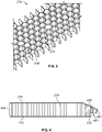
- Figure 3 provides an isometric view of an acoustic treatment member 214 of an acoustic panel 113.
- Each acoustic panel 113 comprises an acoustic treatment member 214 extending between a radially inner skin 215 and radially outer skin 216.
- the acoustic treatment member 214 comprises a plurality of walls 217 that define a plurality of radially-oriented cells 218.
- the walls 217 define a plurality of radially oriented cells 218 in a honeycomb as shown in Figure 3 .
- the walls 217 may comprise aluminum or composite.
- the acoustic treatment member 214 may entirely overlay the radially inner skin 215.
- the acoustic panel 113 of Figure 2 comprises an acoustic treatment member 214 radially bound by the radially inner skin 215 and radially outer skin 216.
- the radially inner skin 215 faces the rotatable shaft 103 of the engine 101.
- the radially inner skin 215 may define at least a portion of a radially outer boundary of a gas flowpath of the engine, such as the bypass flowpath 106.
- the radially inner skin 215 may be arcuate.
- the radially outer skin 216 faces away from the rotatable shaft 103 and toward the casing 109.
- the radially outer skin 216 may define a radially outward facing mating surface 219.
- the radially outer skin 216 may be arcuate.
- Each of the radially inner skin 215 and radially outer skin 216 may comprise composite, such as a fiber reinforced composite such as fiberglass or similar material.
- an acoustic panel 113 may be affixed to a casing 109 using fasteners. In some embodiments, an acoustic panel 113 may be carried in whole or in part by structures of the casing 109. The acoustic panel 113 may be axially and/or radially retained by such structures. An example of such an embodiment is provided in in Figures 4 and 5 .
- the acoustic panel 113 is shaped to form a lip 451 along a first axial edge 452 of the acoustic panel 113.
- the lip 451 is formed by filling the radially oriented cells 218 adjacent the first axial edge 452 with a reinforcement material 455 and by machining away a portion of the radially inner skin 215 and acoustic treatment member 214.
- the reinforcement material 455 may completely or partly fill each cell 218 that intersects the lip 451. Partly filled cells 218 may be partly filled in a radial or axial direction.
- the reinforcement material 455 may completely or partly fill each cell that intersects the lip 451 as well as adjacent cells.
- the lip 451 is shaped having sufficient strength to support a portion of the acoustic panel 113 along the first axial edge 452.
- the reinforcement material 455 may be an elastomer, such as a potting material.
- the lip 451 defines a radially inward facing mating surface 453.
- the acoustic panel 113 may taper toward the first axial edge 452.
- the acoustic panel 113 may be affixed to the casing 109 along a second axial edge 454 opposite the first axial edge 452 with fasteners.
- a hook 456 extends radially and axially from the casing 109.
- the hook 456 comprises a radial member 457 extending radially inward from the casing 109 and an axial member 458 extending axially forward from the radial member 457 and spaced from the casing 109.
- the axial member 458 may define a groove 459 that axially and radially retains a damper ring 460 positioned between the acoustic panel 113 and the hook 456. More specifically, the damper ring 460 may be positioned between the radially inward facing mating surface 453 of the lip 451 and the axial member 458 of the hook 456.
- the hook 456 and damper ring 460 may be annular and the hook 456 may form a continuous surface for carrying or retaining the acoustic panel 113.
- the acoustic panel 113 may be axially retained by the radial member 457 and radially retained by the axial member 458.
- the damper ring 460 may be formed from a flexible or semi-rigid material and may serve to allow a degree of relative movement between the acoustic panel 113 and hook 456 without excessive vibrations.
- the damper ring 460 may be referred to and serve as a radial bumper bearing.
- a wall portion 461 may protrude beyond the radially inward facing mating surface 453 due to imperfections or inconsistencies in the machining process.
- the radially inward facing mating surface 453 of the lip 451 may wear over time, for example due to differing wear rates between the walls 217 and reinforcement material 455, and result in a wall portion 461 protruding beyond the radially inward facing mating surface 453.
- a protruding wall portion 461 may be undesirable as it may damage the damper ring 460. This damage can lead to degradation and/or failure of the damper ring 460, thus causing harmful leak-by past the radial bumper bearing and/or vibrations of the acoustic panel 113.
- the radially inward facing mating surface 453 is lined or covered with a protective member 462.
- a protective member 462 Such an embodiment is illustrated in Figure 7 .
- the protective member 462 may comprise a layer of paint, a single- or multi-ply fiberglass cover or fiberglass tape, or a composite.
- the protective member 462 may be applied to areas beyond that illustrated in Figure 7 to include, in some embodiments, the first axial edge 452 and axially facing surfaces of the lip 451.
- FIG 8 is a schematic cross-sectional view of an acoustic panel 113 affixed to a casing 109, with the cross section taken along an axis A of the engine 101, in accordance with some embodiments of the present disclosure.
- an acoustic panel assembly 800 or system for acoustic dampening in a rotating machine such as an engine 101 may comprise an annular casing 109 and an acoustic panel 113 affixed to the annular casing 109.
- the annular casing 109 of the engine 101 is disposed radially outward of at least a portion of the rotatable shaft 103.
- the annular casing 109 may comprise a hook 456 that extends radially inward and axially from the casing 109.
- the acoustic panel 113 comprises a radially inner skin 215, radially outer skin 216, and an acoustic treatment member 214 partly bounded by the radially inner skin 215 and radially outer skin 216.
- the acoustic treatment member 214 comprises a plurality of radially oriented walls 217 extending between the radially inner skin 215 and radially outer skin 216 to form a plurality of radially oriented cells 218.
- a portion of the cells 218 adjacent a first axial edge 452 of the acoustic panel 113 are filled with a reinforcement material 455 and the acoustic panel 113 is shaped along the first axial edge 452 to form a lip 451 having sufficient strength to support the acoustic panel 113 along the first axial edge 452.
- the acoustic panel 113 is positioned so that the lip 451 is axially and radially retained by the hook 456.
- the acoustic panel 113 may be affixed to the casing 109 along a second axial edge 454 of the acoustic panel 113 with fasteners (not shown). In other embodiments, the acoustic panel 113 may be carried along a second axial edge 454 by a second hook or similar structure.
- An acoustic panel array 1000 may be formed from one or more acoustic panels 113 arranged about the circumference of a casing 109.
- Figure 10 provides a schematic cross sectional view of an acoustic panel array 1000, with the cross section taken looking down the axis A of the engine 101.
- the acoustic panels 113 of the acoustic panel array 1000 may be axially aligned with each other.
- Each of the acoustic panels 113 may be positioned as described above with reference to Figure 8 , such that each acoustic panel 113 has a lip 451 that is axially and radially retained by a hook 456.
- the acoustic panels 113 may be positioned about the circumference of the casing 109 and may be axially aligned to form an annulus of acoustic panels 113 that is an acoustic panel array 1000.
- the acoustic panel array 1000 comprises three or more acoustic panels 113. Each acoustic panel 113 may be separated from an adjacent panel by a gap 1002.
- the present disclosure additionally provides methods of forming an acoustic panel 113 for dampening noise in a rotating machine such as an engine 101.
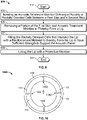
- One such method 900 is presented in the flow diagram of Figure 9 .
- Method 900 starts at Block 901.
- the steps of method 900, presented at Blocks 901 through 911, may be performed in the order presented in Figure 9 or in another order.
- One or more steps of the method 900 may not be performed.
- an acoustic treatment member 214 is bonded between a radially inner skin 215, or first skin, and a radially outer skin 216, or second skin.
- the acoustic treatment member 214 comprises a plurality of walls 217 extending between the first skin and second skin to thereby define a plurality of radially oriented cells 218.
- a portion of the first skin and acoustic treatment member 214 is removed to thereby form a lip 451.
- the portion may be removed by machining of the acoustic panel 113.
- the radially oriented cells 218 that intersect the lip 451 are at least partly filled with a reinforcement material 455.
- the cells 218 that intersect the mounting groove and any adjacent cell 218 may be filled.
- the reinforcement material 455 may be an elastomer. With filling the cells 218 with reinforcement material 455, a lip 451 is formed having sufficient strength to support the acoustic panel 113 along an axial edge of the acoustic panel 113.
- the steps of Block 905 and 907 may be executed in reverse order from that presented in Figure 9 .
- the lip 451 is lined with a protective member 462.
- the protective member 462 may comprise a layer of paint, a single- or multi-ply fiberglass cover or fiberglass tape, or a composite.
- the method 900 may further include the step of curing the reinforcement material 455 after Block 907. Method 900 ends at Block 911.
- the presently disclosed systems and methods provide advantages over the prior art of dampening noise in a rotating machine.
- the present disclosure reduces the number of fasteners required to affix the acoustic panel the casing. Reducing the number of fasteners is desirable as it results in a less complex system, greater ease of manufacturing, greater volume of acoustic treatment members available for treatment of noise, and greater ease of installation and removal of the acoustic panel.
- the use of a structurally reinforced lip also eliminates the need for a separate article of the acoustic panel, such as a compression molded rail, to form the first axial edge of the panel.
- the present disclosure additionally provides a protective member between the lip and a hook of the casing in order to reduce or prevent damage to the acoustic panel lip, the hook, or any damper rings therebetween.
- the protective member may protect: (1) the reinforcement material from being damaged by the edges of the walls or the hook, (2) the edges of the walls from being damages by the hook, and (3) the damper ring from being damaged by the edges of the walls.
- the protective member may also help distribute the contact forces more evenly across the walls and reinforcement material.
Landscapes
- Engineering & Computer Science (AREA)
- Chemical & Material Sciences (AREA)
- Combustion & Propulsion (AREA)
- Mechanical Engineering (AREA)
- General Engineering & Computer Science (AREA)
- Physics & Mathematics (AREA)
- Acoustics & Sound (AREA)
- Multimedia (AREA)
- Structures Of Non-Positive Displacement Pumps (AREA)
- Soundproofing, Sound Blocking, And Sound Damping (AREA)
Description
- Acoustic panels may be used in rotating machines to reduce, dampen, or treat noise emanating from the machine. For example, acoustic panels may be used in modern gas turbine engines in an effort to meet regulatory restrictions on noise emissions from the engine. Generally speaking, acoustic panels may be used to line radially outer portions of gas flowpaths in the engine. The acoustic panels typically comprise a structure or materials that reduce, dampen, or treat noise.
-
US 2010/0206664 describes an acoustic panel for a fan casing of a gas turbine engine includes one or more Helmholtz resonators to absorb acoustic energy propagated upstream from the fan.EP 0 894613 describes a method of forming a composite acoustic panel with a sacrificial sheet that is machined off as the upper side of the core material is shaped.JP 2006 002869 US 5756182 describes an acoustic tile for masking the acoustic signature of a surface or submarine vessel and including an inner skin for securing the tile to the hull of the vessel, an outer water-impervious skin, and a core sandwiched between the inner and outer skins, the core being made of an expanded honeycomb structure being affixed to said inner and outer skins by thermocompression bonding. - The present disclosure provides an acoustic panel assembly for dampening noise in a rotating machine and a method of forming an acoustic panel as set out in the appended claims.
- According to some aspects of the present disclosure, an acoustic panel assembly is disclosed for dampening noise in a rotating machine. The rotating machine comprises a rotatable shaft defining an axis of rotation. The acoustic panel assembly comprises an annular casing, a hook, and an acoustic panel. The annular casing is disposed about at least a portion of the rotatable shaft. The hook extends radially inward and axially from the casing. The acoustic panel comprises a radially inner skin, a radially outer skin, and an acoustic treatment member. The acoustic treatment member comprises a plurality of walls extending between the radially inner skin and the radially outer skin thereby defining a plurality of radially oriented cells. A portion of the radially oriented cells adjacent a first axial edge of the acoustic panel is filled with a reinforcement material and shaped to form a lip having sufficient strength to support the acoustic panel along the first axial edge. The acoustic panel is positioned so that the lip is axially and radially retained by the hook to thereby support the first axial edge of the acoustic panel from the casing. The lip defines a radially inward facing mating surface. At least a portion of the mating surface is covered with a protective member. The protective member is disposed between the lip and the hook.
- In some embodiments, the acoustic panel assembly further comprises a damper ring positioned between the protective member and the hook. In some embodiments, the lip is formed along the first axial edge of the acoustic panel. The acoustic panel is affixed to the casing proximate a second axial edge opposite the first axial edge. In some embodiments, the acoustic panel is affixed by a fastener.
- By providing for a lip of an acoustic panel having sufficient strength to support a portion of the panel, the present disclosure may reduce the number of fasteners required to affix the acoustic panel the casing. Reducing the number of fasteners may be desirable as it results in a less complex system, greater ease of manufacturing, greater volume of acoustic treatment members available for treatment of noise, and greater ease of installation and removal of the acoustic panel. The use of a structurally reinforced lip may also eliminate the need for a separate article of the acoustic panel, such as a compression molded rail, to form the first axial edge of the panel.
- The protective member between the lip and the hook of the casing may reduce or prevent damage to the acoustic panel lip, the hook, or any damper rings therebetween. The protective member may protect: (1) the reinforcement material from being damaged by the edges of the walls or the hook, (2) the edges of the walls from being damages by the hook, and (3) the damper ring from being damaged by the edges of the walls. The protective member may also help distribute the contact forces more evenly across the walls and reinforcement material.
- In some embodiments, the plurality of radially oriented cells form a honeycomb pattern. In some embodiments, the hook comprises a radial member extending radially inward from the casing and an axial member extending axially from the radial member and being spaced from the casing. In some embodiments, the acoustic panel is radially retained by the axial member of the hook.
- According to further aspects of the present disclosure, an acoustic panel array is disclosed for dampening noise in a rotating machine. The rotating machine comprises a rotatable shaft defining an axis of rotation. The acoustic panel array comprises an annular casing, an annular hook, and three or more acoustic panels. The annular casing is disposed about at least a portion of the rotatable shaft. The annular hook extends radially inward and axially from the casing. Each of the three or more acoustic panels comprises a radially inner skin, a radially outer skin, and an acoustic treatment member. The acoustic treatment member comprises a plurality of walls extending between the radially inner skin and the radially outer skin thereby defining a plurality of radially oriented cells. A portion of the radially oriented cells adjacent a first axial edge of the acoustic panel is filled with a reinforcement material and shaped to form a lip having sufficient strength to support the first axial edge of the acoustic panel. Each of the acoustic panels is positioned so that the lip is axially and radially retained by the hook to thereby support the first axial edge of the acoustic panel from the casing. The three or more acoustic panels are positioned about a circumference of the annular casing and are axially aligned to form an annulus of acoustic panels.
- In some embodiments, each of the acoustic panels is separated from an adjacent panel by a gap. In some embodiments, the lip of each acoustic panel defines a radially inward facing mating surface. The mating surface is lined with a protective member. In some embodiments, the acoustic panel array further comprises an annular damper ring positioned between the protective member of each acoustic panel and the hook. In some embodiments, the lip of each acoustic panel is formed along a first axial edge of the acoustic panel. The acoustic panel is affixed to the annular casing proximate a second axial edge opposite the first axial edge via a fastener.
- According to yet further aspects of the present disclosure, a method is disclosed of forming an acoustic panel for dampening noise in a rotating machine. The method comprises bonding an acoustic treatment member between a first skin and a second skin. The acoustic treatment member comprises a plurality of walls extending between the first skin and the second skin to thereby define a plurality of radially oriented cells. The method further comprises removing a portion of the first skin and the acoustic treatment member adjacent an axial edge of the acoustic panel to thereby form a lip. The method further comprises filling the radially oriented cells that intersect the lip with a reinforcement material to thereby form the lip to have sufficient strength to support the acoustic panel along the lip. The lip defines a radially inward facing mating surface. The method further comprises lining at least a portion of said mating surface with a protective member to protect an edge of the walls from being damaged by a hook of an annular casing of the rotating machine.
- In some embodiments, the step of filling the radially oriented cells comprises filling all radially oriented cells that intersect the lip and are adjacent the axial edge with the reinforcement material. In some embodiments, the method further comprises curing the reinforcement material. In some embodiments, the reinforcement material is an elastomer. In some embodiments, the protective member comprises a composite. In some embodiments, the protective member comprises fiberglass.
- The following will be apparent from elements of the figures, which are provided for illustrative purposes.
-
Fig. 1 is a schematic cross-sectional view of acoustic panels positioned in a rotating machine in accordance with some embodiments of the present disclosure. -
Fig. 2 is a schematic cross-sectional view of an acoustic panel in accordance with some embodiments of the present disclosure. -
Fig. 3 is an isometric view of an acoustic treatment member of an acoustic panel in accordance with some embodiments of the present disclosure. -
Fig. 4 is a schematic cross-sectional view of a portion of an acoustic panel affixed to a casing in accordance with some embodiments of the present disclosure. -
Fig. 5 is a schematic cross-sectional view of an acoustic panel in accordance with some embodiments of the present disclosure. -
Fig. 6 is a schematic cross-sectional view of a portion of an acoustic panel in accordance with some embodiments of the present disclosure. -
Fig. 7 is a schematic cross-sectional view of a portion of an acoustic panel in accordance with some embodiments of the present disclosure. -
Fig. 8 is a schematic cross-sectional view of an acoustic panel affixed to a casing in accordance with some embodiments of the present disclosure. -
Fig. 9 is a flow diagram of a method in accordance with some embodiments of the present disclosure. -
Fig. 10 is a schematic cross sectional view of an acoustic panel array in accordance with some embodiments of the present disclosure. - The present application discloses illustrative (i.e., example) embodiments. The claimed inventions are not limited to the illustrative embodiments. Therefore, the present invention is not intended to be limited to the embodiments shown here but it is to be accorded the widest scope consistent with the appended claims.
- For the purposes of promoting an understanding of the principles of the disclosure, reference will now be made to a number of illustrative embodiments in the drawings and specific language will be used to describe the same.
- The present disclosure is directed to systems and methods of acoustic dampening in rotating machines. A system for acoustic dampening may include an acoustic panel comprising an inner skin, an outer skin, and an acoustic treatment member extending between the inner and outer skins. The acoustic treatment member may define a plurality of radially oriented cells. A portion of the acoustic treatment member may be shaped to form a lip, and cells along or intercepting the lip may be filled with a reinforcement material such that the lip has sufficient strength to support the acoustic panel when mounted to a casing of the rotating machine. The lip may be axially and radially retained by a hook extending from the casing. A method of acoustic dampening may include forming an acoustic panel as described above and affixing the panel to the casing.
-
Figure 1 presents a schematic cross-sectional view of the placement ofacoustic panels 113 in a rotating machine. The rotating machine in the examples provided throughout this disclosure is agas turbine engine 101, although the disclosure is not so limited. Theengine 101 may comprise afan 102 driven by aturbine 104 via arotatable shaft 103. Theshaft 103 defines an axis of rotation A. Air passing through thefan 102 is split into acore flowpath 105 and abypass flowpath 106. Thecore flowpath 105 comprises acompressor 107,combustor 108, andturbine 104. Thebypass flowpath 106 is disposed radially outward of thecore flowpath 105. Theengine 101 is encased by acasing 109. Thecasing 109 may define aninlet cowl 110. Afan liner 111 may be affixed to thecasing 109 and positioned radially outward of thefan 102. Theengine 101 may have athrust reverser 112. - The
acoustic panels 113 may be positioned generally in one or more of the following locations: in theinlet cowl 110 forward of thefan liner 111; in theinlet cowl 110 aft of thefan liner 111; along thecasing 109 that defines a portion of thebypass flowpath 106; or in thethrust reverser 112. One or moreacoustic panels 113 may be arranged about the circumference of a gas flowpath to form an annular acoustic panel array. An array may be formed by any number ofacoustic panels 113. For example, an annular acoustic panel array may be formed by fouracoustic panels 113 positioned in axial alignment about a circumference of a gas flowpath. -
Figure 2 provides a schematic cross-sectional view of anacoustic panel 113, with the cross section taken along an axis of rotation A of the rotating machine.Figure 3 provides an isometric view of anacoustic treatment member 214 of anacoustic panel 113. - Each
acoustic panel 113 comprises anacoustic treatment member 214 extending between a radiallyinner skin 215 and radiallyouter skin 216. Theacoustic treatment member 214 comprises a plurality ofwalls 217 that define a plurality of radially-orientedcells 218. Thewalls 217 define a plurality of radially orientedcells 218 in a honeycomb as shown inFigure 3 . Thewalls 217 may comprise aluminum or composite. Theacoustic treatment member 214 may entirely overlay the radiallyinner skin 215. - The
acoustic panel 113 ofFigure 2 comprises anacoustic treatment member 214 radially bound by the radiallyinner skin 215 and radiallyouter skin 216. The radiallyinner skin 215 faces therotatable shaft 103 of theengine 101. The radiallyinner skin 215 may define at least a portion of a radially outer boundary of a gas flowpath of the engine, such as thebypass flowpath 106. The radiallyinner skin 215 may be arcuate. - The radially
outer skin 216 faces away from therotatable shaft 103 and toward thecasing 109. The radiallyouter skin 216 may define a radially outward facingmating surface 219. The radiallyouter skin 216 may be arcuate. Each of the radiallyinner skin 215 and radiallyouter skin 216 may comprise composite, such as a fiber reinforced composite such as fiberglass or similar material. - In some embodiments an
acoustic panel 113 may be affixed to acasing 109 using fasteners. In some embodiments, anacoustic panel 113 may be carried in whole or in part by structures of thecasing 109. Theacoustic panel 113 may be axially and/or radially retained by such structures. An example of such an embodiment is provided in inFigures 4 and5 . - The
acoustic panel 113 is shaped to form alip 451 along a firstaxial edge 452 of theacoustic panel 113. Thelip 451 is formed by filling the radially orientedcells 218 adjacent the firstaxial edge 452 with areinforcement material 455 and by machining away a portion of the radiallyinner skin 215 andacoustic treatment member 214. Thereinforcement material 455 may completely or partly fill eachcell 218 that intersects thelip 451. Partly filledcells 218 may be partly filled in a radial or axial direction. Thereinforcement material 455 may completely or partly fill each cell that intersects thelip 451 as well as adjacent cells. With use of thereinforcement material 455, thelip 451 is shaped having sufficient strength to support a portion of theacoustic panel 113 along the firstaxial edge 452. Thereinforcement material 455 may be an elastomer, such as a potting material. - The
lip 451 defines a radially inward facingmating surface 453. Theacoustic panel 113 may taper toward the firstaxial edge 452. Theacoustic panel 113 may be affixed to thecasing 109 along a secondaxial edge 454 opposite the firstaxial edge 452 with fasteners. - A
hook 456 extends radially and axially from thecasing 109. In the illustrated embodiment ofFigure 5 , thehook 456 comprises aradial member 457 extending radially inward from thecasing 109 and anaxial member 458 extending axially forward from theradial member 457 and spaced from thecasing 109. Theaxial member 458 may define agroove 459 that axially and radially retains adamper ring 460 positioned between theacoustic panel 113 and thehook 456. More specifically, thedamper ring 460 may be positioned between the radially inward facingmating surface 453 of thelip 451 and theaxial member 458 of thehook 456. - The
hook 456 anddamper ring 460 may be annular and thehook 456 may form a continuous surface for carrying or retaining theacoustic panel 113. Theacoustic panel 113 may be axially retained by theradial member 457 and radially retained by theaxial member 458. Thedamper ring 460 may be formed from a flexible or semi-rigid material and may serve to allow a degree of relative movement between theacoustic panel 113 and hook 456 without excessive vibrations. Thedamper ring 460 may be referred to and serve as a radial bumper bearing. - As shown in
Figure 6 , in forming the lip 451 awall portion 461 may protrude beyond the radially inward facingmating surface 453 due to imperfections or inconsistencies in the machining process. Similarly, the radially inward facingmating surface 453 of thelip 451 may wear over time, for example due to differing wear rates between thewalls 217 andreinforcement material 455, and result in awall portion 461 protruding beyond the radially inward facingmating surface 453. A protrudingwall portion 461 may be undesirable as it may damage thedamper ring 460. This damage can lead to degradation and/or failure of thedamper ring 460, thus causing harmful leak-by past the radial bumper bearing and/or vibrations of theacoustic panel 113. - As a result, in the invention the radially inward facing
mating surface 453 is lined or covered with aprotective member 462. Such an embodiment is illustrated inFigure 7 . Theprotective member 462 may comprise a layer of paint, a single- or multi-ply fiberglass cover or fiberglass tape, or a composite. Theprotective member 462 may be applied to areas beyond that illustrated inFigure 7 to include, in some embodiments, the firstaxial edge 452 and axially facing surfaces of thelip 451. -
Figure 8 is a schematic cross-sectional view of anacoustic panel 113 affixed to acasing 109, with the cross section taken along an axis A of theengine 101, in accordance with some embodiments of the present disclosure. As shown inFigure 8 , anacoustic panel assembly 800 or system for acoustic dampening in a rotating machine such as anengine 101 may comprise anannular casing 109 and anacoustic panel 113 affixed to theannular casing 109. - The
annular casing 109 of theengine 101 is disposed radially outward of at least a portion of therotatable shaft 103. Theannular casing 109 may comprise ahook 456 that extends radially inward and axially from thecasing 109. - The
acoustic panel 113 comprises a radiallyinner skin 215, radiallyouter skin 216, and anacoustic treatment member 214 partly bounded by the radiallyinner skin 215 and radiallyouter skin 216. Theacoustic treatment member 214 comprises a plurality of radially orientedwalls 217 extending between the radiallyinner skin 215 and radiallyouter skin 216 to form a plurality of radially orientedcells 218. A portion of thecells 218 adjacent a firstaxial edge 452 of theacoustic panel 113 are filled with areinforcement material 455 and theacoustic panel 113 is shaped along the firstaxial edge 452 to form alip 451 having sufficient strength to support theacoustic panel 113 along the firstaxial edge 452. - The
acoustic panel 113 is positioned so that thelip 451 is axially and radially retained by thehook 456. Theacoustic panel 113 may be affixed to thecasing 109 along a secondaxial edge 454 of theacoustic panel 113 with fasteners (not shown). In other embodiments, theacoustic panel 113 may be carried along a secondaxial edge 454 by a second hook or similar structure. - An
acoustic panel array 1000 may be formed from one or moreacoustic panels 113 arranged about the circumference of acasing 109.Figure 10 provides a schematic cross sectional view of anacoustic panel array 1000, with the cross section taken looking down the axis A of theengine 101. Theacoustic panels 113 of theacoustic panel array 1000 may be axially aligned with each other. Each of theacoustic panels 113 may be positioned as described above with reference toFigure 8 , such that eachacoustic panel 113 has alip 451 that is axially and radially retained by ahook 456. Theacoustic panels 113 may be positioned about the circumference of thecasing 109 and may be axially aligned to form an annulus ofacoustic panels 113 that is anacoustic panel array 1000. In some embodiments theacoustic panel array 1000 comprises three or moreacoustic panels 113. Eachacoustic panel 113 may be separated from an adjacent panel by agap 1002. - The present disclosure additionally provides methods of forming an
acoustic panel 113 for dampening noise in a rotating machine such as anengine 101. Onesuch method 900 is presented in the flow diagram ofFigure 9 .Method 900 starts atBlock 901. The steps ofmethod 900, presented atBlocks 901 through 911, may be performed in the order presented inFigure 9 or in another order. One or more steps of themethod 900 may not be performed. - At
Block 903 anacoustic treatment member 214 is bonded between a radiallyinner skin 215, or first skin, and a radiallyouter skin 216, or second skin. Theacoustic treatment member 214 comprises a plurality ofwalls 217 extending between the first skin and second skin to thereby define a plurality of radially orientedcells 218. - At Block 905 a portion of the first skin and
acoustic treatment member 214 is removed to thereby form alip 451. The portion may be removed by machining of theacoustic panel 113. - At
Block 907 the radially orientedcells 218 that intersect thelip 451 are at least partly filled with areinforcement material 455. Thecells 218 that intersect the mounting groove and anyadjacent cell 218 may be filled. Thereinforcement material 455 may be an elastomer. With filling thecells 218 withreinforcement material 455, alip 451 is formed having sufficient strength to support theacoustic panel 113 along an axial edge of theacoustic panel 113. Notably, the steps ofBlock Figure 9 . - At
Block 909 thelip 451 is lined with aprotective member 462. Theprotective member 462 may comprise a layer of paint, a single- or multi-ply fiberglass cover or fiberglass tape, or a composite. - The
method 900 may further include the step of curing thereinforcement material 455 afterBlock 907.Method 900 ends atBlock 911. - The presently disclosed systems and methods provide advantages over the prior art of dampening noise in a rotating machine. By providing for a lip of an acoustic panel having sufficient strength to support a portion of the panel, the present disclosure reduces the number of fasteners required to affix the acoustic panel the casing. Reducing the number of fasteners is desirable as it results in a less complex system, greater ease of manufacturing, greater volume of acoustic treatment members available for treatment of noise, and greater ease of installation and removal of the acoustic panel. The use of a structurally reinforced lip also eliminates the need for a separate article of the acoustic panel, such as a compression molded rail, to form the first axial edge of the panel.
- The present disclosure additionally provides a protective member between the lip and a hook of the casing in order to reduce or prevent damage to the acoustic panel lip, the hook, or any damper rings therebetween. The protective member may protect: (1) the reinforcement material from being damaged by the edges of the walls or the hook, (2) the edges of the walls from being damages by the hook, and (3) the damper ring from being damaged by the edges of the walls. The protective member may also help distribute the contact forces more evenly across the walls and reinforcement material.
- Although examples are illustrated and described herein, embodiments are nevertheless not limited to the details shown, since various modifications and structural changes may be made therein by those of ordinary skill within the scope of the following claims.
Claims (13)
- An acoustic panel assembly (800) for dampening noise in a rotating machine (101), the rotating machine (101) comprising a rotatable shaft (103) defining an axis of rotation (A), the acoustic panel assembly (800) comprising:an annular casing (109) disposed about at least a portion of the rotatable shaft (103);a hook (456) extending radially inward and axially from said casing (109); andan acoustic panel (113) comprising:a radially inner skin (215);a radially outer skin (216); andan acoustic treatment member (214) comprising a plurality of walls (217) extending between the radially inner skin (215) and the radially outer skin (216) thereby defining a plurality of radially oriented cells (218), a portion of the radially oriented cells (218) adjacent a first axial edge (452) of said acoustic panel (113) being shaped to form a lip (451),wherein said acoustic panel (113) is positioned so that said lip (451) is axially and radially retained by said hook (456) to thereby support the first axial edge (452) of saidacoustic panel (113) from said casing (109); characterized in that said portion of the radially oriented cells (218) adjacent a first axial edge (452) of said acoustic panel (113) are filled with a reinforcement material (455) and shaped to form the lip (451) thereby having sufficient strength to support said acoustic panel (113) along the first axial edge (452); and in thatthe lip (451) defines a radially inward facing mating surface (453), and wherein at least a portion of said mating surface (453) is covered with a protective member (462), the protective member disposed between the lip (451) and the hook (456).
- The acoustic panel assembly (800) of claim 1, further comprising a damper ring (460) positioned between the protective member (462) and the hook (456).
- The acoustic panel assembly (800) of any one of claims 1 or 2, wherein the lip (451) is formed along the first axial edge (452) of the acoustic panel (113), and wherein the acoustic panel (113) is affixed to the casing (109) proximate a second axial edge (454) opposite the first axial edge (452).
- The acoustic panel assembly (800) of claim 3, wherein the acoustic panel (113) is affixed by a fastener.
- The acoustic panel assembly (800) of any one of claims 1 to 4, wherein the plurality of radially oriented cells (218) form a honeycomb pattern.
- The acoustic panel assembly (800) of any one of claims 1 to 5, wherein the hook (456) comprises a radial member (457) extending radially inward from the casing (109) and an axial member (458) extending axially from the radial member (457) and being spaced from said casing (109).
- The acoustic panel assembly (800) of claim 6, wherein the acoustic panel (113) is radially retained by said axial member (458) of said hook (456).
- A method (900) of forming an acoustic panel (113) for dampening noise in a rotating machine (101), the method (900) comprising:bonding (903) an acoustic treatment member (214) between a first skin (215) and a second skin (216), the acoustic treatment member (214) comprising a plurality of walls (217) extending between the first skin (215) and the second skin (216) to thereby define a plurality of radially oriented cells (218);removing (905) a portion of the first skin (215) and the acoustic treatment member (214) adjacent an axial edge (452) of said acoustic panel (113) to thereby form a lip (451); characterized in that the method further comprises filling (907) the radially oriented cells (218) that intersect the lip (451) with a reinforcement material (455) to thereby form the lip (451) to have sufficient strength to support said acoustic panel (113) along said lip (451); and in that the lip (451) defines a radially inward facing mating surface (453); and in that the method further compriseslining (909) at least a portion of said mating surface (453) with a protective member (462) to protect an edge of the walls (217) from being damaged by a hook (456) of an annular casing (109) of the rotating machine (101).
- The method (900) of claim 8, wherein filling the radially oriented cells (218) comprises filling all radially oriented cells (218) that intersect the lip (451) and are adjacent the axial edge (452) with the reinforcement material (455).
- The method (900) of any one of claims 8 or 9, further comprising:
curing the reinforcement material (455). - The method (900) of any one of claims 8 to 10, wherein said reinforcement material (455) is an elastomer.
- The method (900) of any one of claims 8 to 11, wherein said protective member (462) comprises a composite.
- The method (900) of any one of claims 8 to 12, wherein said protective member (462) comprises fiberglass.
Applications Claiming Priority (1)
| Application Number | Priority Date | Filing Date | Title |
|---|---|---|---|
| US16/376,767 US11352953B2 (en) | 2019-04-05 | 2019-04-05 | Acoustic panel with reinforced lip |
Publications (2)
| Publication Number | Publication Date |
|---|---|
| EP3719793A1 EP3719793A1 (en) | 2020-10-07 |
| EP3719793B1 true EP3719793B1 (en) | 2022-10-19 |
Family
ID=70058133
Family Applications (1)
| Application Number | Title | Priority Date | Filing Date |
|---|---|---|---|
| EP20166565.0A Active EP3719793B1 (en) | 2019-04-05 | 2020-03-30 | Acoustic panel assembly with reinforced lip |
Country Status (3)
| Country | Link |
|---|---|
| US (1) | US11352953B2 (en) |
| EP (1) | EP3719793B1 (en) |
| CA (1) | CA3077874A1 (en) |
Family Cites Families (21)
| Publication number | Priority date | Publication date | Assignee | Title |
|---|---|---|---|---|
| US5756182A (en) | 1989-12-04 | 1998-05-26 | Supracor Systems, Inc. | Method and apparatus for masking the acoustic signature of vessels |
| GB2319589B (en) | 1996-11-22 | 1999-06-16 | Rolls Royce Plc | Acoustic panel retention |
| US6179943B1 (en) | 1997-07-30 | 2001-01-30 | The Boeing Company | Method for forming a composite acoustic panel |
| FR2844303B1 (en) | 2002-09-10 | 2006-05-05 | Airbus France | TUBULAR ACOUSTICAL ATTENUATION PIECE FOR AIRCRAFT REACTOR AIR INTAKE |
| US6920958B2 (en) | 2003-10-17 | 2005-07-26 | The Boeing Company | Annular acoustic panel |
| GB2407344B (en) | 2003-10-22 | 2006-02-22 | Rolls Royce Plc | A liner for a gas turbine engine casing |
| FR2869360B1 (en) | 2004-04-27 | 2006-07-14 | Airbus France Sas | NOISE REDUCING ASSEMBLY FOR AIRCRAFT TURBOJET ENGINE |
| JP2006002869A (en) | 2004-06-18 | 2006-01-05 | Toho Tenax Co Ltd | Sandwich panel |
| GB0610271D0 (en) | 2006-05-24 | 2006-07-05 | Rolls Royce Plc | A gas turbine engine casing |
| GB0704879D0 (en) | 2007-03-14 | 2007-04-18 | Rolls Royce Plc | A Casing arrangement |
| US20100206664A1 (en) * | 2007-07-12 | 2010-08-19 | Rolls-Royce Plc | Acoustic panel |
| GB2458679B (en) | 2008-03-28 | 2010-04-21 | Rolls Royce Plc | Acoustic liners |
| US8028802B2 (en) | 2008-06-30 | 2011-10-04 | General Electric Company | Method and system for damped acoustic panels |
| FR2963949A1 (en) * | 2010-08-18 | 2012-02-24 | Aircelle Sa | BEAM PARTICULARLY FOR THRUST INVERTER WITH GRILLS |
| FR2999650B1 (en) | 2012-12-17 | 2018-07-13 | Safran Aircraft Engines | REMOVABLE ACOUSTIC PANELS FOR TURBOREACTOR HOUSING. |
| US9702375B2 (en) | 2013-07-16 | 2017-07-11 | United Technologies Corporation | Liner attaching scheme |
| US9938852B2 (en) | 2014-04-30 | 2018-04-10 | The Boeing Company | Noise attenuating lipskin assembly and methods of assembling the same |
| US9290274B2 (en) | 2014-06-02 | 2016-03-22 | Mra Systems, Inc. | Acoustically attenuating sandwich panel constructions |
| US9447576B2 (en) * | 2015-01-09 | 2016-09-20 | Rohr, Inc. | Post bond perforation of a septum in an acoustic panel |
| US9771726B2 (en) * | 2015-05-18 | 2017-09-26 | Innovative Construction Technologies, LLC | Flooring product and method of manufacturing same |
| US9779715B1 (en) * | 2016-07-26 | 2017-10-03 | Hexcel Corporation | Method for making contoured acoustic structures |
-
2019
- 2019-04-05 US US16/376,767 patent/US11352953B2/en active Active
-
2020
- 2020-03-30 EP EP20166565.0A patent/EP3719793B1/en active Active
- 2020-04-03 CA CA3077874A patent/CA3077874A1/en active Pending
Also Published As
| Publication number | Publication date |
|---|---|
| US20200318540A1 (en) | 2020-10-08 |
| EP3719793A1 (en) | 2020-10-07 |
| US11352953B2 (en) | 2022-06-07 |
| CA3077874A1 (en) | 2020-10-05 |
Similar Documents
| Publication | Publication Date | Title |
|---|---|---|
| EP1673279B1 (en) | Annular acoustic panel for an aircraft engine asembly | |
| US11313324B2 (en) | Systems and methods of acoustic dampening in a gas turbine engine | |
| EP4019754B1 (en) | Acoustic liner with varied properties | |
| EP2815084B1 (en) | Gas turbine case with ballistic liner | |
| EP3447306B1 (en) | Fan containment case for gas turbine engine | |
| EP2952696B1 (en) | Turbofan engine assembly with fan case liner cartridge | |
| US20110044807A1 (en) | Adjustable fan case liner and mounting method | |
| EP3967860B1 (en) | Acoustic attenuation structures | |
| US11174815B2 (en) | Inlet deep cavity flutter liner | |
| EP4206448B1 (en) | Multi-core acoustic panel for an aircraft propulsion system | |
| US10723476B2 (en) | Ring of turbojet vanes including an acoustic treatment structure | |
| EP3281192A1 (en) | Acoustic liner and method of constructing an acoustic liner | |
| US20010048048A1 (en) | Backside fitting attachment for nacelle acoustic panels | |
| EP3084178B1 (en) | Layered ice liner | |
| US11352953B2 (en) | Acoustic panel with reinforced lip | |
| US20230193824A1 (en) | Turbine engine acoustic panel with outer flange case mounting | |
| US11946414B2 (en) | Manufacture methods and apparatus for turbine engine acoustic panels | |
| US20220018283A1 (en) | Acoustic management, on a turbomachine or a nacelle | |
| US20250122840A1 (en) | Acoustic panel having oblique cavities | |
| US12084977B1 (en) | Gas turbine engine with fan track liner having triply periodic minimal surface reinforcement | |
| US20250282466A1 (en) | Aircraft acoustic panel with integrated fire-resistant material | |
| US10954964B2 (en) | Gas turbine engine and panel for a gas turbine engine |
Legal Events
| Date | Code | Title | Description |
|---|---|---|---|
| PUAI | Public reference made under article 153(3) epc to a published international application that has entered the european phase |
Free format text: ORIGINAL CODE: 0009012 |
|
| STAA | Information on the status of an ep patent application or granted ep patent |
Free format text: STATUS: THE APPLICATION HAS BEEN PUBLISHED |
|
| AK | Designated contracting states |
Kind code of ref document: A1 Designated state(s): AL AT BE BG CH CY CZ DE DK EE ES FI FR GB GR HR HU IE IS IT LI LT LU LV MC MK MT NL NO PL PT RO RS SE SI SK SM TR |
|
| AX | Request for extension of the european patent |
Extension state: BA ME |
|
| STAA | Information on the status of an ep patent application or granted ep patent |
Free format text: STATUS: REQUEST FOR EXAMINATION WAS MADE |
|
| 17P | Request for examination filed |
Effective date: 20210317 |
|
| RBV | Designated contracting states (corrected) |
Designated state(s): AL AT BE BG CH CY CZ DE DK EE ES FI FR GB GR HR HU IE IS IT LI LT LU LV MC MK MT NL NO PL PT RO RS SE SI SK SM TR |
|
| GRAP | Despatch of communication of intention to grant a patent |
Free format text: ORIGINAL CODE: EPIDOSNIGR1 |
|
| STAA | Information on the status of an ep patent application or granted ep patent |
Free format text: STATUS: GRANT OF PATENT IS INTENDED |
|
| INTG | Intention to grant announced |
Effective date: 20220719 |
|
| GRAS | Grant fee paid |
Free format text: ORIGINAL CODE: EPIDOSNIGR3 |
|
| GRAA | (expected) grant |
Free format text: ORIGINAL CODE: 0009210 |
|
| STAA | Information on the status of an ep patent application or granted ep patent |
Free format text: STATUS: THE PATENT HAS BEEN GRANTED |
|
| AK | Designated contracting states |
Kind code of ref document: B1 Designated state(s): AL AT BE BG CH CY CZ DE DK EE ES FI FR GB GR HR HU IE IS IT LI LT LU LV MC MK MT NL NO PL PT RO RS SE SI SK SM TR |
|
| REG | Reference to a national code |
Ref country code: GB Ref legal event code: FG4D |
|
| REG | Reference to a national code |
Ref country code: CH Ref legal event code: EP |
|
| REG | Reference to a national code |
Ref country code: DE Ref legal event code: R096 Ref document number: 602020005674 Country of ref document: DE |
|
| REG | Reference to a national code |
Ref country code: IE Ref legal event code: FG4D |
|
| REG | Reference to a national code |
Ref country code: AT Ref legal event code: REF Ref document number: 1526060 Country of ref document: AT Kind code of ref document: T Effective date: 20221115 |
|
| REG | Reference to a national code |
Ref country code: LT Ref legal event code: MG9D |
|
| REG | Reference to a national code |
Ref country code: NL Ref legal event code: MP Effective date: 20221019 |
|
| REG | Reference to a national code |
Ref country code: AT Ref legal event code: MK05 Ref document number: 1526060 Country of ref document: AT Kind code of ref document: T Effective date: 20221019 |
|
| PG25 | Lapsed in a contracting state [announced via postgrant information from national office to epo] |
Ref country code: NL Free format text: LAPSE BECAUSE OF FAILURE TO SUBMIT A TRANSLATION OF THE DESCRIPTION OR TO PAY THE FEE WITHIN THE PRESCRIBED TIME-LIMIT Effective date: 20221019 |
|
| PG25 | Lapsed in a contracting state [announced via postgrant information from national office to epo] |
Ref country code: SE Free format text: LAPSE BECAUSE OF FAILURE TO SUBMIT A TRANSLATION OF THE DESCRIPTION OR TO PAY THE FEE WITHIN THE PRESCRIBED TIME-LIMIT Effective date: 20221019 Ref country code: PT Free format text: LAPSE BECAUSE OF FAILURE TO SUBMIT A TRANSLATION OF THE DESCRIPTION OR TO PAY THE FEE WITHIN THE PRESCRIBED TIME-LIMIT Effective date: 20230220 Ref country code: NO Free format text: LAPSE BECAUSE OF FAILURE TO SUBMIT A TRANSLATION OF THE DESCRIPTION OR TO PAY THE FEE WITHIN THE PRESCRIBED TIME-LIMIT Effective date: 20230119 Ref country code: LT Free format text: LAPSE BECAUSE OF FAILURE TO SUBMIT A TRANSLATION OF THE DESCRIPTION OR TO PAY THE FEE WITHIN THE PRESCRIBED TIME-LIMIT Effective date: 20221019 Ref country code: FI Free format text: LAPSE BECAUSE OF FAILURE TO SUBMIT A TRANSLATION OF THE DESCRIPTION OR TO PAY THE FEE WITHIN THE PRESCRIBED TIME-LIMIT Effective date: 20221019 Ref country code: ES Free format text: LAPSE BECAUSE OF FAILURE TO SUBMIT A TRANSLATION OF THE DESCRIPTION OR TO PAY THE FEE WITHIN THE PRESCRIBED TIME-LIMIT Effective date: 20221019 Ref country code: AT Free format text: LAPSE BECAUSE OF FAILURE TO SUBMIT A TRANSLATION OF THE DESCRIPTION OR TO PAY THE FEE WITHIN THE PRESCRIBED TIME-LIMIT Effective date: 20221019 |
|
| PG25 | Lapsed in a contracting state [announced via postgrant information from national office to epo] |
Ref country code: RS Free format text: LAPSE BECAUSE OF FAILURE TO SUBMIT A TRANSLATION OF THE DESCRIPTION OR TO PAY THE FEE WITHIN THE PRESCRIBED TIME-LIMIT Effective date: 20221019 Ref country code: PL Free format text: LAPSE BECAUSE OF FAILURE TO SUBMIT A TRANSLATION OF THE DESCRIPTION OR TO PAY THE FEE WITHIN THE PRESCRIBED TIME-LIMIT Effective date: 20221019 Ref country code: LV Free format text: LAPSE BECAUSE OF FAILURE TO SUBMIT A TRANSLATION OF THE DESCRIPTION OR TO PAY THE FEE WITHIN THE PRESCRIBED TIME-LIMIT Effective date: 20221019 Ref country code: IS Free format text: LAPSE BECAUSE OF FAILURE TO SUBMIT A TRANSLATION OF THE DESCRIPTION OR TO PAY THE FEE WITHIN THE PRESCRIBED TIME-LIMIT Effective date: 20230219 Ref country code: HR Free format text: LAPSE BECAUSE OF FAILURE TO SUBMIT A TRANSLATION OF THE DESCRIPTION OR TO PAY THE FEE WITHIN THE PRESCRIBED TIME-LIMIT Effective date: 20221019 Ref country code: GR Free format text: LAPSE BECAUSE OF FAILURE TO SUBMIT A TRANSLATION OF THE DESCRIPTION OR TO PAY THE FEE WITHIN THE PRESCRIBED TIME-LIMIT Effective date: 20230120 |
|
| P01 | Opt-out of the competence of the unified patent court (upc) registered |
Effective date: 20230528 |
|
| REG | Reference to a national code |
Ref country code: DE Ref legal event code: R097 Ref document number: 602020005674 Country of ref document: DE |
|
| PG25 | Lapsed in a contracting state [announced via postgrant information from national office to epo] |
Ref country code: SM Free format text: LAPSE BECAUSE OF FAILURE TO SUBMIT A TRANSLATION OF THE DESCRIPTION OR TO PAY THE FEE WITHIN THE PRESCRIBED TIME-LIMIT Effective date: 20221019 Ref country code: RO Free format text: LAPSE BECAUSE OF FAILURE TO SUBMIT A TRANSLATION OF THE DESCRIPTION OR TO PAY THE FEE WITHIN THE PRESCRIBED TIME-LIMIT Effective date: 20221019 Ref country code: EE Free format text: LAPSE BECAUSE OF FAILURE TO SUBMIT A TRANSLATION OF THE DESCRIPTION OR TO PAY THE FEE WITHIN THE PRESCRIBED TIME-LIMIT Effective date: 20221019 Ref country code: DK Free format text: LAPSE BECAUSE OF FAILURE TO SUBMIT A TRANSLATION OF THE DESCRIPTION OR TO PAY THE FEE WITHIN THE PRESCRIBED TIME-LIMIT Effective date: 20221019 Ref country code: CZ Free format text: LAPSE BECAUSE OF FAILURE TO SUBMIT A TRANSLATION OF THE DESCRIPTION OR TO PAY THE FEE WITHIN THE PRESCRIBED TIME-LIMIT Effective date: 20221019 |
|
| PLBE | No opposition filed within time limit |
Free format text: ORIGINAL CODE: 0009261 |
|
| STAA | Information on the status of an ep patent application or granted ep patent |
Free format text: STATUS: NO OPPOSITION FILED WITHIN TIME LIMIT |
|
| PG25 | Lapsed in a contracting state [announced via postgrant information from national office to epo] |
Ref country code: SK Free format text: LAPSE BECAUSE OF FAILURE TO SUBMIT A TRANSLATION OF THE DESCRIPTION OR TO PAY THE FEE WITHIN THE PRESCRIBED TIME-LIMIT Effective date: 20221019 Ref country code: AL Free format text: LAPSE BECAUSE OF FAILURE TO SUBMIT A TRANSLATION OF THE DESCRIPTION OR TO PAY THE FEE WITHIN THE PRESCRIBED TIME-LIMIT Effective date: 20221019 |
|
| 26N | No opposition filed |
Effective date: 20230720 |
|
| REG | Reference to a national code |
Ref country code: DE Ref legal event code: R119 Ref document number: 602020005674 Country of ref document: DE |
|
| PG25 | Lapsed in a contracting state [announced via postgrant information from national office to epo] |
Ref country code: MC Free format text: LAPSE BECAUSE OF FAILURE TO SUBMIT A TRANSLATION OF THE DESCRIPTION OR TO PAY THE FEE WITHIN THE PRESCRIBED TIME-LIMIT Effective date: 20221019 |
|
| REG | Reference to a national code |
Ref country code: CH Ref legal event code: PL |
|
| PG25 | Lapsed in a contracting state [announced via postgrant information from national office to epo] |
Ref country code: SI Free format text: LAPSE BECAUSE OF FAILURE TO SUBMIT A TRANSLATION OF THE DESCRIPTION OR TO PAY THE FEE WITHIN THE PRESCRIBED TIME-LIMIT Effective date: 20221019 |
|
| REG | Reference to a national code |
Ref country code: BE Ref legal event code: MM Effective date: 20230331 |
|
| PG25 | Lapsed in a contracting state [announced via postgrant information from national office to epo] |
Ref country code: LU Free format text: LAPSE BECAUSE OF NON-PAYMENT OF DUE FEES Effective date: 20230330 |
|
| REG | Reference to a national code |
Ref country code: IE Ref legal event code: MM4A |
|
| PG25 | Lapsed in a contracting state [announced via postgrant information from national office to epo] |
Ref country code: LI Free format text: LAPSE BECAUSE OF NON-PAYMENT OF DUE FEES Effective date: 20230331 Ref country code: IE Free format text: LAPSE BECAUSE OF NON-PAYMENT OF DUE FEES Effective date: 20230330 Ref country code: DE Free format text: LAPSE BECAUSE OF NON-PAYMENT OF DUE FEES Effective date: 20231003 Ref country code: CH Free format text: LAPSE BECAUSE OF NON-PAYMENT OF DUE FEES Effective date: 20230331 |
|
| PG25 | Lapsed in a contracting state [announced via postgrant information from national office to epo] |
Ref country code: BE Free format text: LAPSE BECAUSE OF NON-PAYMENT OF DUE FEES Effective date: 20230331 |
|
| PG25 | Lapsed in a contracting state [announced via postgrant information from national office to epo] |
Ref country code: IT Free format text: LAPSE BECAUSE OF FAILURE TO SUBMIT A TRANSLATION OF THE DESCRIPTION OR TO PAY THE FEE WITHIN THE PRESCRIBED TIME-LIMIT Effective date: 20221019 |
|
| PG25 | Lapsed in a contracting state [announced via postgrant information from national office to epo] |
Ref country code: BG Free format text: LAPSE BECAUSE OF FAILURE TO SUBMIT A TRANSLATION OF THE DESCRIPTION OR TO PAY THE FEE WITHIN THE PRESCRIBED TIME-LIMIT Effective date: 20221019 |
|
| GBPC | Gb: european patent ceased through non-payment of renewal fee |
Effective date: 20240330 |
|
| PG25 | Lapsed in a contracting state [announced via postgrant information from national office to epo] |
Ref country code: BG Free format text: LAPSE BECAUSE OF FAILURE TO SUBMIT A TRANSLATION OF THE DESCRIPTION OR TO PAY THE FEE WITHIN THE PRESCRIBED TIME-LIMIT Effective date: 20221019 |
|
| PG25 | Lapsed in a contracting state [announced via postgrant information from national office to epo] |
Ref country code: GB Free format text: LAPSE BECAUSE OF NON-PAYMENT OF DUE FEES Effective date: 20240330 |
|
| PG25 | Lapsed in a contracting state [announced via postgrant information from national office to epo] |
Ref country code: GB Free format text: LAPSE BECAUSE OF NON-PAYMENT OF DUE FEES Effective date: 20240330 |
|
| PG25 | Lapsed in a contracting state [announced via postgrant information from national office to epo] |
Ref country code: CY Free format text: LAPSE BECAUSE OF FAILURE TO SUBMIT A TRANSLATION OF THE DESCRIPTION OR TO PAY THE FEE WITHIN THE PRESCRIBED TIME-LIMIT; INVALID AB INITIO Effective date: 20200330 |
|
| PG25 | Lapsed in a contracting state [announced via postgrant information from national office to epo] |
Ref country code: HU Free format text: LAPSE BECAUSE OF FAILURE TO SUBMIT A TRANSLATION OF THE DESCRIPTION OR TO PAY THE FEE WITHIN THE PRESCRIBED TIME-LIMIT; INVALID AB INITIO Effective date: 20200330 |
|
| PG25 | Lapsed in a contracting state [announced via postgrant information from national office to epo] |
Ref country code: TR Free format text: LAPSE BECAUSE OF FAILURE TO SUBMIT A TRANSLATION OF THE DESCRIPTION OR TO PAY THE FEE WITHIN THE PRESCRIBED TIME-LIMIT Effective date: 20221019 |
|
| PGFP | Annual fee paid to national office [announced via postgrant information from national office to epo] |
Ref country code: FR Payment date: 20260323 Year of fee payment: 7 |