EP3719770A1 - Photoelectric smoke detectors - Google Patents
Photoelectric smoke detectors Download PDFInfo
- Publication number
- EP3719770A1 EP3719770A1 EP20164963.9A EP20164963A EP3719770A1 EP 3719770 A1 EP3719770 A1 EP 3719770A1 EP 20164963 A EP20164963 A EP 20164963A EP 3719770 A1 EP3719770 A1 EP 3719770A1
- Authority
- EP
- European Patent Office
- Prior art keywords
- smoke
- detector
- opening
- recited
- cover
- Prior art date
- Legal status (The legal status is an assumption and is not a legal conclusion. Google has not performed a legal analysis and makes no representation as to the accuracy of the status listed.)
- Granted
Links
Images




Classifications
-
- G—PHYSICS
- G08—SIGNALLING
- G08B—SIGNALLING SYSTEMS, e.g. PERSONAL CALLING SYSTEMS; ORDER TELEGRAPHS; ALARM SYSTEMS
- G08B17/00—Fire alarms; Alarms responsive to explosion
- G08B17/10—Actuation by presence of smoke or gases, e.g. automatic alarm devices for analysing flowing fluid materials by the use of optical means
- G08B17/103—Actuation by presence of smoke or gases, e.g. automatic alarm devices for analysing flowing fluid materials by the use of optical means using a light emitting and receiving device
- G08B17/107—Actuation by presence of smoke or gases, e.g. automatic alarm devices for analysing flowing fluid materials by the use of optical means using a light emitting and receiving device for detecting light-scattering due to smoke
-
- G—PHYSICS
- G01—MEASURING; TESTING
- G01N—INVESTIGATING OR ANALYSING MATERIALS BY DETERMINING THEIR CHEMICAL OR PHYSICAL PROPERTIES
- G01N15/00—Investigating characteristics of particles; Investigating permeability, pore-volume or surface-area of porous materials
- G01N15/06—Investigating concentration of particle suspensions
-
- G—PHYSICS
- G01—MEASURING; TESTING
- G01N—INVESTIGATING OR ANALYSING MATERIALS BY DETERMINING THEIR CHEMICAL OR PHYSICAL PROPERTIES
- G01N33/00—Investigating or analysing materials by specific methods not covered by groups G01N1/00 - G01N31/00
- G01N33/0004—Gaseous mixtures, e.g. polluted air
- G01N33/0009—General constructional details of gas analysers, e.g. portable test equipment
- G01N33/0027—General constructional details of gas analysers, e.g. portable test equipment concerning the detector
- G01N33/0036—General constructional details of gas analysers, e.g. portable test equipment concerning the detector specially adapted to detect a particular component
- G01N33/004—CO or CO2
-
- G—PHYSICS
- G08—SIGNALLING
- G08B—SIGNALLING SYSTEMS, e.g. PERSONAL CALLING SYSTEMS; ORDER TELEGRAPHS; ALARM SYSTEMS
- G08B17/00—Fire alarms; Alarms responsive to explosion
- G08B17/10—Actuation by presence of smoke or gases, e.g. automatic alarm devices for analysing flowing fluid materials by the use of optical means
- G08B17/117—Actuation by presence of smoke or gases, e.g. automatic alarm devices for analysing flowing fluid materials by the use of optical means by using a detection device for specific gases, e.g. combustion products, produced by the fire
-
- G—PHYSICS
- G01—MEASURING; TESTING
- G01N—INVESTIGATING OR ANALYSING MATERIALS BY DETERMINING THEIR CHEMICAL OR PHYSICAL PROPERTIES
- G01N15/00—Investigating characteristics of particles; Investigating permeability, pore-volume or surface-area of porous materials
- G01N15/06—Investigating concentration of particle suspensions
- G01N15/075—Investigating concentration of particle suspensions by optical means
Definitions
- This application relates to smoke detectors, and more particularly photoelectric smoke detectors.
- a photoelectric smoke detector includes a light source and a photoelectric receiver to detect whether or not smoke is present. Smoke is determined to be present when a change in the amount of light received at the photoelectric receiver exceeds a pre-determined value. Upon the smoke detector determining smoke is present, a fire alarm is tripped.
- a photoelectric smoke detector includes an optics cover that provides a smoke chamber that has a smoke chamber opening and, a CO detector mounted to the optics cover.
- An inner cover provides a first opening and a second opening. The first opening receives a portion of the CO detector and the second opening is aligned with the smoke chamber opening.
- a spoiler includes a U-shaped fin arrangement and is received against the inner cover.
- the second opening has a contour substantially the same as a contour of a lip of the optics cover that provides the smoke chamber opening.
- the first opening is substantially T-shaped.
- the second opening is substantially D-shaped.
- the inner cover includes a divider portion that separates the first opening from the second opening.
- the U-shaped fin portion abuts the divider portion.
- the inner cover includes first and second projections angled to create a tapered path across an outer portion of the inner cover.
- the spoiler includes a ring portion, and a conical portion that extends from the ring portion.
- the U-shaped fin arrangement extends from the conical portion.
- the conical portion tapers as it extends toward the optics cover.
- an outer cover is attached to a base portion, and the outer cover includes an open entry portion.
- a gap is provided between the CO detector and the outer cover.
- the inner cover seals the gap from the entry portion to prevent smoke particles from entering the gap.
- the entry portion includes a first row of openings, a second row of openings, and a third row of openings.
- a bottom surface of the inner cover is flush with an upper surface of the first row of openings.
- an outer edge of the spoiler is received against a horizontal bar between the second row of openings and the third row of openings.
- the inner cover is heat staked to an outer cover.
- the inner cover is snap-fit to an outer cover.
- bug screen is positioned over the smoke chamber opening.
- the U-shaped fin arrangement extends to a plane that is provided at an outer lip of the smoke chamber, and the outer lip provides the smoke chamber opening.
- the U-shaped fin arrangement is open toward the CO detector.
- the U-shaped fin arrangement includes a first fin portion substantially parallel to the top of a central axis of the CO detector.
- a second fin portion and a third fin portion are substantially parallel to the second fin portion.
- a photoelectric smoke detector includes a base portion, a circuit received on the base portion, an optics cover that is mounted to the base portion and provides a smoke chamber that has a smoke chamber opening.
- a CO detector is mounted to the optics cover.
- An inner cover provides a first opening and a second opening. The first opening receives a portion of the CO detector and the second opening is aligned with the smoke chamber opening.
- a spoiler includes a ring portion, a conical portion that extends from the ring portion toward the smoke chamber, and a U-shaped fin arrangement that extends from the conical portion. The spoiler is received against the inner cover.
- An outer cover is attached to a base portion. The outer cover includes an open entry portion. A gap is provided between the CO detector and the outer cover, and the inner cover seals the gap from the entry portion to prevent smoke particles from entering the gap.
- Figure 1 illustrates a prior art smoke detector 20.
- a base portion 22 for mounting to a surface, such as a ceiling in some examples, is provided.
- An optics cover 24 is attached to the base portion 22 and provides a smoke chamber 26.
- the example smoke detector 20 is a photoelectric smoke detector.
- a light source (not shown) is aimed into the smoke chamber 26 at an angle away from a receiver (not shown).
- the smoke detector 20 is a multi-wave multi-angle photoelectric smoke detector, as is known to include multiple photoelectric elements, such as several light sources and/or several receivers, to allow for multiple different types of signals.
- a carbon monoxide (CO) detector 28 is mounted to the optics cover 24 outside of the smoke chamber 26 for detecting the presence of carbon monoxide.
- An outer cover 30 attaches to the base portion 22 but is shown as removed from the base portion 22 for ease of viewing.
- the outer cover 30 includes an open entry portion 32 for allowing smoke particles to enter the smoke detector 20 for detection.
- a circuit board 33 may be provided between the optics cover 24 and the base portion 22 to mechanically support and electrically connect electronic components of the smoke detector 20.
- the smoke detector 20 may include one or more inserts (not shown) for directing smoke particles from the entry portion 32 into the smoke chamber 26.
- Applicant has identified that when smoke enters in certain directions of entry, such as directions of entry near the CO detector 28, prior art smoke detectors 20 are less efficient at directing smoke into the smoke chamber 26 for detection than when smoke enters from other directions.
- FIG. 2 illustrates an improved smoke detector 120. It should be understood that like reference numerals identify corresponding or similar elements throughout the several drawings.
- An inner cover 134 and a spoiler 136 are provided in the smoke detector 120 to uniformly direct smoke particles entering the smoke detector from all directions into the smoke chamber 126 and to prevent smoke particles from entering gaps outside of the smoke chamber 126.
- the inner cover 134 provides an opening 138 contoured to receive a portion of the CO detector 128 and an opening 140 positioned to align with the opening 142 of the optics cover 124.
- the opening 138 is substantially T-shaped to accommodate two differently sized cylindrical portions of the CO detector 128. Other shapes may be used to accommodate differently shaped CO detectors in some examples.
- the opening 140 has substantially the same contour as the opening 142.
- the openings 140, 142 are substantially D-shaped.
- the lip 143 of the opening 142 has substantially the same contour as the perimeter of the opening 140. Other shapes may be utilized to accommodate differently shaped smoke chambers in some examples.
- a porous bug screen 144 may be placed over the opening 142 to prevent insects and the like from entering the smoke chamber 126.
- the outer cover 130, the inner cover 134, and the spoiler 136 are shown in exploded form for ease of viewing, but, when assembled, the inner cover 134 is received against the CO detector 128 and the optics cover 124, and the spoiler 136 is received against the inner cover 134. As discussed further below, in some examples, the inner cover 134 may be attached to an inner surface of the outer cover 130.
- the inner cover 134 and the spoiler 136 are made of thermoplastic materials. In some examples the inner cover 134 and the spoiler 136 are made of acrylonitrile butadiene styrene (ABS).
- ABS acrylonitrile butadiene styrene
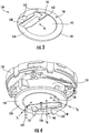
- Figure 3 illustrates the inner cover 134 shown in Figure 2 .
- the inner cover 134 includes an outer portion 146 providing an outer edge 148.
- the outer edge 148 of the inner cover 134 is shaped to be received by the outer cover 130 as described below with reference to Figure 5 .
- the outer portion 146 may have a taper.
- outer portion 146 may provide a circular outer edge 148 and the outer portion 146 may have a conical taper.
- a dividing portion 150 separates the opening 138 from the opening 140.
- the inner cover 134 may further include projections 152 extending from a bottom surface 154.
- the inner cover 134 may be positioned about a central axis A1 relative to the outer edge 148 in some examples. As shown, the axis A1 extends through the opening 140 in some examples.
- the inner cover 134 may include a light pipe aperture 155 for receiving a light pipe indicator 157 (see Figure 4 ).
- Figure 4 illustrates the inner cover 134 received against the optics cover 124.
- the bottom surface 154 faces away from the base portion 122 when assembled.
- a light pipe 157 received into the inner cover 134 may direct light from within the detector 120, such as from a light-emitting diode or other light source, to the outside of the detector 120, or may direct light received from outside of the detector 120 to a sensor or other device within the detector 120 and above inner cover 134.
- the inner cover 134 is received in abutment against the lip 143 (not shown; see Figure 2 ) and the CO detector 128, such that smoke particles moving across the bottom surface 154 are directed toward the smoke chamber 126.
- smoke particles S1, S3 entering the smoke detector 120 move across the bottom surface 154 of the inner cover 134 and into the smoke chamber 126.
- Smoke particles S2 entering in directions near the CO detector 128 move across the bottom surface 154 and the bottom surface 156 of the CO detector 128 before entering the smoke chamber 126.
- the projections 152 are angled to direct smoke particles S2 toward the smoke chamber 126 by providing a tapered path across the bottom surface 154 of the outer portion 146 of the inner cover 134 before the particles move over the CO detector 128.
- the inner cover 134, the optics cover 124, and CO detector 128 are engaged in a sealing manner to prevent gaps within the smoke detector 120 but outside of the smoke chamber 126 that may trap smoke S1, S2, S3 outside of the smoke chamber 126.
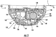
- Figure 5 illustrates a cross-sectional view of the example smoke detector 120.
- the outer edge 148 of the inner cover 134 is received against the inner surface 158 of the outer cover 130 to prevent smoke from entering gaps other than the smoke chamber 126, such as the gap 160 between the CO detector 128 and the outer cover 130 in some examples.
- the bottom surface 154 of the outer portion 146 is substantially flush with the upper surface 162 of the entry portion 132.
- smoke particles S2 may move across a ceiling C, down the outer surface of the outer cover 130, into the smoke detector 120 through the entry portion 132 and across the surface 162, across the bottom surface 154 at the outer portion 146, across the CO detector 128, across the bottom surface 154 at the dividing portion 150 and into the smoke chamber 126. Some smoke particles may deflect off a fin 164 of the spoiler 136 toward the smoke chamber 126, as discussed further below.
- Figure 6 illustrates the spoiler 136 oriented in the upward direction U as it would be within a ceiling mounted configuration of the smoke detector 120.
- Fins 166 and 168 connect to and extend from the fin 164 to form a U-shaped fin arrangement 170.
- the U-shaped fin arrangement 170 is positioned to be open toward the CO detector 128 (see Figure 5 ). That is, the open side of the U-shaped fin arrangement 170 is nearer the CO detector 128 than the fin 164.
- One or more of the fins 164, 166, 168 of the U-shaped fin arrangement 170 may include straight portions.
- the spoiler 136 includes a ring portion 172 and a conical portion 174 extending upwardly from the ring portion 172.
- the U-shaped fin arrangement 170 extends from the conical portion 174.
- the spoiler 136 provides an opening 176 inward (relative to the outer edge 178) of the U-shaped fin arrangement 170.
- the U-shaped fin arrangement 170 is open toward a void 177 in the conical portion 174 that extends from the opening 176.
- the ring portion 172 includes an outer edge 178, which may have a number of notches 180 for receiving posts (not shown) of the entry portion 132.
- the ring portion 172 may be positioned about a central axis A2.
- the spoiler 136 may include a light pipe groove 181 for receiving a light pipe indicator 157 (shown in Figure 4 ).
- smoke particles S2 may deflect off the fin 164 and into the smoke chamber 126 (not shown).
- Smoke particles S4 may move along the ring portion 172 and conical portion 174 and deflect off the fin 168 and upward into the smoke chamber 126.
- Smoke particles S5 may move along the ring portion 172 and conical portion 174 and deflect off the fin 166 and upward into the smoke chamber 126.
- Smoke particles S6 may move along the ring portion 172 and conical portion 174 and deflect off the fin 164 and upward into the smoke chamber 126.
- Figure 7 shows a cross sectional view of the example smoke detector 120, showing smoke particle paths S5 and S6, with reference to Figure 6 .
- the example conical portion 174 tapers as it extends upward toward the smoke chamber 126 to form a continuous surface from the entry portion 132 to the leading edge of the chamber 126.
- the outer edge 178 of the spoiler 136 is received against the inner surface 158 of the outer cover 130 at the entry portion 132.
- the entry portion 132 provides three rows of openings 182A, 182B, and 182C, and the edge 178 is received against the horizontal bar 184 between the lower two rows 182B and 182C.
- the fins 164, 166, 168 extend to a plane P at the lip 143 of the smoke chamber 126. In some examples, as shown the bug screen 144 may be positioned along the plane P. Other heights can be utilized in some examples.
- the fins 164, 166, 168 extend from the conical portion 174 upward toward the smoke chamber 126.
- Figure 8 illustrates the spoiler 136 received against the bar 184 of the entry portion 132 of the outer cover 130.
- the notches 180 receive the posts 186 of the entry portion.
- Figure 9 illustrates the inner cover 134 attached to the outer cover 130.
- the inner cover 134 is heat staked to the outer cover 130.
- the inner cover 134 is snap fit to the outer cover 130.
- the inner cover 134 includes tabs 188 for attachment to the outer cover 130.
- the fin 164 When assembled, the fin 164 is substantially parallel to the central axis A3 of the CO detector 128 (not shown). In some examples, as shown, the fins 166 and 168 are substantially parallel to one another. As shown, the projections 152 provide a tapered path toward the opening of the U-shaped fin arrangement 170. The void 177 is positioned within the same circumferential region as the CO detector 128 (not shown). The ends of the fins 166, 168 may be received against the dividing portion 150. The outer cover 130 may be positioned relative to a central axis A4, such that the axes A1, A2, and A4 are substantially aligned.
- the example smoke detector 120 utilizes Brownian motion principles for the motion of smoke particles within air. Brownian principles describe the ability of small smoke particles to remain suspended due to interactions with the atmosphere with motions that are energetic enough to resist the pull of gravity which would force these particles to fall to earth.
- the inner cover 134 seals gaps and prevents smoke particles from settling within the gaps instead of moving into the smoke chamber 126.
- the placement and angling of the various surfaces, fins, and projections of the inner cover 134 and spoiler 136 in the illustrative example direct smoke particles into the smoke chamber 126 in an improved, uniform manner relative to the prior art. Detection among various angles of entry relative to the horizontal plane of the smoke detector 120 is more uniform as compared to prior art smoke detectors.
- Figure 10 illustrates a graph, for the various positions shown in the horizontal plane P2 of the prior art smoke detector 20, of smoke in air denoted by obscuration per foot (OBS/ft) against the analog signal converted to a digital output (AD) of refracted light detected by the photodiode from the forward scatter infrared LED.
- the Forward (F) infrared (IR) LED emits radiation in the smoke chamber 26 and some of this radiation is scattered in the forward direction towards the photodiode which is a direct function of obscuration % of smoke.
- Each of the curves represent the behavior of a single smoke detector for its specified angle of entry of the smoke path into the prior art smoke detector 20. A wide variation of signal response is observed. That is, as seen, there was significant variance of detection among the various angles of entry into the prior art smoke detector 20.
- Figure 11 illustrates a similar graph for the corresponding various positions in the horizontal plane P3 of the example smoke detector 120.
- the inner cover 134 and the spoiler 136 of the illustrative example facilitate a uniform signal regardless of orientation of smoke entry into the example smoke detector 120.
- the detector 120 is more equally sensitive in all orientations.
- One of ordinary skill in the art having the benefit of this disclosure would recognize that certain modifications could be made to the illustrative example, while still achieving similar benefits.
Landscapes
- Chemical & Material Sciences (AREA)
- Physics & Mathematics (AREA)
- Analytical Chemistry (AREA)
- General Physics & Mathematics (AREA)
- Health & Medical Sciences (AREA)
- Life Sciences & Earth Sciences (AREA)
- Biochemistry (AREA)
- Pathology (AREA)
- Immunology (AREA)
- General Health & Medical Sciences (AREA)
- Business, Economics & Management (AREA)
- Emergency Management (AREA)
- Engineering & Computer Science (AREA)
- Dispersion Chemistry (AREA)
- Medicinal Chemistry (AREA)
- Food Science & Technology (AREA)
- Combustion & Propulsion (AREA)
- Fire-Detection Mechanisms (AREA)
- Investigating Or Analysing Materials By Optical Means (AREA)
Abstract
Description
- This application relates to smoke detectors, and more particularly photoelectric smoke detectors.
- A photoelectric smoke detector includes a light source and a photoelectric receiver to detect whether or not smoke is present. Smoke is determined to be present when a change in the amount of light received at the photoelectric receiver exceeds a pre-determined value. Upon the smoke detector determining smoke is present, a fire alarm is tripped.
- A photoelectric smoke detector according to the present invention includes an optics cover that provides a smoke chamber that has a smoke chamber opening and, a CO detector mounted to the optics cover. An inner cover provides a first opening and a second opening. The first opening receives a portion of the CO detector and the second opening is aligned with the smoke chamber opening. A spoiler includes a U-shaped fin arrangement and is received against the inner cover.
- Optionally, the second opening has a contour substantially the same as a contour of a lip of the optics cover that provides the smoke chamber opening.
- Optionally, the first opening is substantially T-shaped.
- Optionally, the second opening is substantially D-shaped.
- Optionally, the inner cover includes a divider portion that separates the first opening from the second opening.
- Optionally, the U-shaped fin portion abuts the divider portion.
- Optionally, the inner cover includes first and second projections angled to create a tapered path across an outer portion of the inner cover.
- Optionally, the spoiler includes a ring portion, and a conical portion that extends from the ring portion. The U-shaped fin arrangement extends from the conical portion.
- Optionally, the conical portion tapers as it extends toward the optics cover.
- Optionally, an outer cover is attached to a base portion, and the outer cover includes an open entry portion.
- Optionally, a gap is provided between the CO detector and the outer cover. The inner cover seals the gap from the entry portion to prevent smoke particles from entering the gap.
- Optionally, the entry portion includes a first row of openings, a second row of openings, and a third row of openings. A bottom surface of the inner cover is flush with an upper surface of the first row of openings.
- Optionally, an outer edge of the spoiler is received against a horizontal bar between the second row of openings and the third row of openings.
- Optionally, the inner cover is heat staked to an outer cover.
- Optionally, the inner cover is snap-fit to an outer cover.
- Optionally, bug screen is positioned over the smoke chamber opening.
- Optionally, the U-shaped fin arrangement extends to a plane that is provided at an outer lip of the smoke chamber, and the outer lip provides the smoke chamber opening.
- Optionally, the U-shaped fin arrangement is open toward the CO detector.
- Optionally, the U-shaped fin arrangement includes a first fin portion substantially parallel to the top of a central axis of the CO detector. A second fin portion and a third fin portion are substantially parallel to the second fin portion.
- A photoelectric smoke detector according to an example includes a base portion, a circuit received on the base portion, an optics cover that is mounted to the base portion and provides a smoke chamber that has a smoke chamber opening. A CO detector is mounted to the optics cover. An inner cover provides a first opening and a second opening. The first opening receives a portion of the CO detector and the second opening is aligned with the smoke chamber opening. A spoiler includes a ring portion, a conical portion that extends from the ring portion toward the smoke chamber, and a U-shaped fin arrangement that extends from the conical portion. The spoiler is received against the inner cover. An outer cover is attached to a base portion. The outer cover includes an open entry portion. A gap is provided between the CO detector and the outer cover, and the inner cover seals the gap from the entry portion to prevent smoke particles from entering the gap.
- These and other features may be best understood from the following specification and drawings, the following of which is a brief description.
-
Figure 1 illustrates a prior art smoke detector. -
Figure 2 illustrates an example smoke detector. -
Figure 3 illustrates an example inner cover of the example smoke detector ofFigure 2 . -
Figure 4 illustrates a portion of the example smoke detector ofFigure 2 . -
Figure 5 illustrates a cross sectional view of the example smoke detector. -
Figure 6 illustrates an example spoiler for the example smoke detector. -
Figure 7 illustrates a cross sectional view of the example smoke detector. -
Figure 8 illustrates the example spoiler ofFigure 6 received within an example outer cover. -
Figure 9 illustrates the example inner cover ofFigure 3 received within the example outer cover. -
Figure 10 illustrates a performance graph of the prior art smoke detector ofFigure 1 . -
Figure 11 illustrates a performance graph of the example smoke detector. -
Figure 1 illustrates a priorart smoke detector 20. Abase portion 22 for mounting to a surface, such as a ceiling in some examples, is provided. Anoptics cover 24 is attached to thebase portion 22 and provides asmoke chamber 26. Theexample smoke detector 20 is a photoelectric smoke detector. In a photoelectric smoke detector, a light source (not shown) is aimed into thesmoke chamber 26 at an angle away from a receiver (not shown). When smoke enters thechamber 26, smoke particles scatter the light from the light source onto the receiver, which then triggers an alarm. In some examples, thesmoke detector 20 is a multi-wave multi-angle photoelectric smoke detector, as is known to include multiple photoelectric elements, such as several light sources and/or several receivers, to allow for multiple different types of signals. - A carbon monoxide (CO)
detector 28 is mounted to theoptics cover 24 outside of thesmoke chamber 26 for detecting the presence of carbon monoxide. Anouter cover 30 attaches to thebase portion 22 but is shown as removed from thebase portion 22 for ease of viewing. Theouter cover 30 includes anopen entry portion 32 for allowing smoke particles to enter thesmoke detector 20 for detection. Acircuit board 33 may be provided between theoptics cover 24 and thebase portion 22 to mechanically support and electrically connect electronic components of thesmoke detector 20. Thesmoke detector 20 may include one or more inserts (not shown) for directing smoke particles from theentry portion 32 into thesmoke chamber 26. - Directional orientations in this disclosure such as "above," "below," "top," "bottom," and the like are made with reference to ceiling mounted smoke detectors, but one of ordinary skill in the art having the benefit of this disclosure would recognize that smoke detectors mounted in other orientations may also benefit.
- Applicant has identified that when smoke enters in certain directions of entry, such as directions of entry near the
CO detector 28, priorart smoke detectors 20 are less efficient at directing smoke into thesmoke chamber 26 for detection than when smoke enters from other directions. -
Figure 2 illustrates animproved smoke detector 120. It should be understood that like reference numerals identify corresponding or similar elements throughout the several drawings. Aninner cover 134 and aspoiler 136 are provided in thesmoke detector 120 to uniformly direct smoke particles entering the smoke detector from all directions into thesmoke chamber 126 and to prevent smoke particles from entering gaps outside of thesmoke chamber 126. - In some examples, as shown, the
inner cover 134 provides anopening 138 contoured to receive a portion of theCO detector 128 and anopening 140 positioned to align with theopening 142 of the optics cover 124. In some examples, as shown, theopening 138 is substantially T-shaped to accommodate two differently sized cylindrical portions of theCO detector 128. Other shapes may be used to accommodate differently shaped CO detectors in some examples. In some examples, as shown, theopening 140 has substantially the same contour as theopening 142. In some examples, as shown, theopenings lip 143 of theopening 142 has substantially the same contour as the perimeter of theopening 140. Other shapes may be utilized to accommodate differently shaped smoke chambers in some examples. In some examples, aporous bug screen 144 may be placed over theopening 142 to prevent insects and the like from entering thesmoke chamber 126. - The
outer cover 130, theinner cover 134, and thespoiler 136 are shown in exploded form for ease of viewing, but, when assembled, theinner cover 134 is received against theCO detector 128 and the optics cover 124, and thespoiler 136 is received against theinner cover 134. As discussed further below, in some examples, theinner cover 134 may be attached to an inner surface of theouter cover 130. - In some examples, the
inner cover 134 and thespoiler 136 are made of thermoplastic materials. In some examples theinner cover 134 and thespoiler 136 are made of acrylonitrile butadiene styrene (ABS). -
Figure 3 illustrates theinner cover 134 shown inFigure 2 . Theinner cover 134 includes anouter portion 146 providing anouter edge 148. Theouter edge 148 of theinner cover 134 is shaped to be received by theouter cover 130 as described below with reference toFigure 5 . In some examples, theouter portion 146 may have a taper. In some examples, such as the example ofFigure 3 ,outer portion 146 may provide a circularouter edge 148 and theouter portion 146 may have a conical taper. A dividingportion 150 separates the opening 138 from theopening 140. Theinner cover 134 may further includeprojections 152 extending from abottom surface 154. Theinner cover 134 may be positioned about a central axis A1 relative to theouter edge 148 in some examples. As shown, the axis A1 extends through theopening 140 in some examples. Theinner cover 134 may include alight pipe aperture 155 for receiving a light pipe indicator 157 (seeFigure 4 ). -
Figure 4 illustrates theinner cover 134 received against the optics cover 124. Thebottom surface 154 faces away from thebase portion 122 when assembled. In some embodiments alight pipe 157 received into theinner cover 134 may direct light from within thedetector 120, such as from a light-emitting diode or other light source, to the outside of thedetector 120, or may direct light received from outside of thedetector 120 to a sensor or other device within thedetector 120 and aboveinner cover 134. Theinner cover 134 is received in abutment against the lip 143 (not shown; seeFigure 2 ) and theCO detector 128, such that smoke particles moving across thebottom surface 154 are directed toward thesmoke chamber 126. - As shown schematically, smoke particles S1, S3 entering the
smoke detector 120 move across thebottom surface 154 of theinner cover 134 and into thesmoke chamber 126. Smoke particles S2 entering in directions near theCO detector 128 move across thebottom surface 154 and thebottom surface 156 of theCO detector 128 before entering thesmoke chamber 126. Theprojections 152 are angled to direct smoke particles S2 toward thesmoke chamber 126 by providing a tapered path across thebottom surface 154 of theouter portion 146 of theinner cover 134 before the particles move over theCO detector 128. Theinner cover 134, the optics cover 124, andCO detector 128 are engaged in a sealing manner to prevent gaps within thesmoke detector 120 but outside of thesmoke chamber 126 that may trap smoke S1, S2, S3 outside of thesmoke chamber 126. -
Figure 5 illustrates a cross-sectional view of theexample smoke detector 120. Theouter edge 148 of theinner cover 134 is received against theinner surface 158 of theouter cover 130 to prevent smoke from entering gaps other than thesmoke chamber 126, such as thegap 160 between theCO detector 128 and theouter cover 130 in some examples. In some examples, as shown, thebottom surface 154 of theouter portion 146 is substantially flush with theupper surface 162 of theentry portion 132. - As shown schematically in
Figure 5 with reference back toFigure 4 , smoke particles S2 may move across a ceiling C, down the outer surface of theouter cover 130, into thesmoke detector 120 through theentry portion 132 and across thesurface 162, across thebottom surface 154 at theouter portion 146, across theCO detector 128, across thebottom surface 154 at the dividingportion 150 and into thesmoke chamber 126. Some smoke particles may deflect off afin 164 of thespoiler 136 toward thesmoke chamber 126, as discussed further below. -
Figure 6 illustrates thespoiler 136 oriented in the upward direction U as it would be within a ceiling mounted configuration of thesmoke detector 120.Fins fin 164 to form aU-shaped fin arrangement 170. TheU-shaped fin arrangement 170 is positioned to be open toward the CO detector 128 (seeFigure 5 ). That is, the open side of theU-shaped fin arrangement 170 is nearer theCO detector 128 than thefin 164. One or more of thefins U-shaped fin arrangement 170 may include straight portions. - The
spoiler 136 includes aring portion 172 and aconical portion 174 extending upwardly from thering portion 172. TheU-shaped fin arrangement 170 extends from theconical portion 174. Thespoiler 136 provides anopening 176 inward (relative to the outer edge 178) of theU-shaped fin arrangement 170. TheU-shaped fin arrangement 170 is open toward a void 177 in theconical portion 174 that extends from theopening 176. Thering portion 172 includes anouter edge 178, which may have a number ofnotches 180 for receiving posts (not shown) of theentry portion 132. Thering portion 172 may be positioned about a central axis A2. In the illustrative example, when assembled the axis A2 of thering portion 172 aligns with the axis A1 of the outer portion 146 (seeFigure 3 ). Thespoiler 136 may include alight pipe groove 181 for receiving a light pipe indicator 157 (shown inFigure 4 ). - As shown schematically in
Figure 6 with reference back toFigures 4 and5 , smoke particles S2 may deflect off thefin 164 and into the smoke chamber 126 (not shown). Smoke particles S4 may move along thering portion 172 andconical portion 174 and deflect off thefin 168 and upward into thesmoke chamber 126. Smoke particles S5 may move along thering portion 172 andconical portion 174 and deflect off thefin 166 and upward into thesmoke chamber 126. Smoke particles S6 may move along thering portion 172 andconical portion 174 and deflect off thefin 164 and upward into thesmoke chamber 126. -
Figure 7 shows a cross sectional view of theexample smoke detector 120, showing smoke particle paths S5 and S6, with reference toFigure 6 . As shown, the exampleconical portion 174 tapers as it extends upward toward thesmoke chamber 126 to form a continuous surface from theentry portion 132 to the leading edge of thechamber 126. Theouter edge 178 of thespoiler 136 is received against theinner surface 158 of theouter cover 130 at theentry portion 132. In some examples, as shown, theentry portion 132 provides three rows ofopenings edge 178 is received against thehorizontal bar 184 between the lower tworows fins lip 143 of thesmoke chamber 126. In some examples, as shown thebug screen 144 may be positioned along the plane P. Other heights can be utilized in some examples. Thefins conical portion 174 upward toward thesmoke chamber 126. -
Figure 8 illustrates thespoiler 136 received against thebar 184 of theentry portion 132 of theouter cover 130. Thenotches 180 receive theposts 186 of the entry portion. -
Figure 9 illustrates theinner cover 134 attached to theouter cover 130. In some examples, theinner cover 134 is heat staked to theouter cover 130. In some examples, theinner cover 134 is snap fit to theouter cover 130. In some examples, theinner cover 134 includestabs 188 for attachment to theouter cover 130. - When assembled, the
fin 164 is substantially parallel to the central axis A3 of the CO detector 128 (not shown). In some examples, as shown, thefins projections 152 provide a tapered path toward the opening of theU-shaped fin arrangement 170. Thevoid 177 is positioned within the same circumferential region as the CO detector 128 (not shown). The ends of thefins portion 150. Theouter cover 130 may be positioned relative to a central axis A4, such that the axes A1, A2, and A4 are substantially aligned. - The
example smoke detector 120 utilizes Brownian motion principles for the motion of smoke particles within air. Brownian principles describe the ability of small smoke particles to remain suspended due to interactions with the atmosphere with motions that are energetic enough to resist the pull of gravity which would force these particles to fall to earth. Theinner cover 134 seals gaps and prevents smoke particles from settling within the gaps instead of moving into thesmoke chamber 126. The placement and angling of the various surfaces, fins, and projections of theinner cover 134 andspoiler 136 in the illustrative example direct smoke particles into thesmoke chamber 126 in an improved, uniform manner relative to the prior art. Detection among various angles of entry relative to the horizontal plane of thesmoke detector 120 is more uniform as compared to prior art smoke detectors. -
Figure 10 illustrates a graph, for the various positions shown in the horizontal plane P2 of the priorart smoke detector 20, of smoke in air denoted by obscuration per foot (OBS/ft) against the analog signal converted to a digital output (AD) of refracted light detected by the photodiode from the forward scatter infrared LED. The Forward (F) infrared (IR) LED emits radiation in thesmoke chamber 26 and some of this radiation is scattered in the forward direction towards the photodiode which is a direct function of obscuration % of smoke. Each of the curves represent the behavior of a single smoke detector for its specified angle of entry of the smoke path into the priorart smoke detector 20. A wide variation of signal response is observed. That is, as seen, there was significant variance of detection among the various angles of entry into the priorart smoke detector 20. -
Figure 11 illustrates a similar graph for the corresponding various positions in the horizontal plane P3 of theexample smoke detector 120. As seen, there was more uniform detection between the various angles of entry into theexample smoke detector 120. Theinner cover 134 and thespoiler 136 of the illustrative example facilitate a uniform signal regardless of orientation of smoke entry into theexample smoke detector 120. Thus, thedetector 120 is more equally sensitive in all orientations. One of ordinary skill in the art having the benefit of this disclosure would recognize that certain modifications could be made to the illustrative example, while still achieving similar benefits. - Although the different examples are illustrated as having specific components, the examples of this disclosure are not limited to those particular combinations. It is possible to use some of the components or features from any of the examples in combination with features or components from any of the other examples.
- The foregoing description shall be interpreted as illustrative and not in any limiting sense. The scope of the invention is defined by the appended claims. A worker of ordinary skill in the art would understand that certain modifications could come within the scope of this disclosure. For these reasons, the following claims should be studied to determine the true scope and content of the present invention.
Claims (15)
- A photoelectric smoke detector, comprising:an optics cover providing a smoke chamber having a smoke chamber opening;a CO detector mounted to the optics cover;an inner cover providing a first opening and a second opening, wherein the first opening receives a portion of the CO detector and the second opening is aligned with the smoke chamber opening;a spoiler including a U-shaped fin arrangement and received against the inner cover.
- The smoke detector as recited in claim 1, wherein the second opening has a contour substantially the same as a contour of a lip of the optics cover providing the smoke chamber opening.
- The smoke detector as recited in claim 1 or 2, wherein the first opening is substantially T-shaped.
- The smoke detector as recited in claim 1, 2 or 3, wherein the second opening is substantially D-shaped.
- The smoke detector as recited in any preceding claim, wherein the inner cover includes a divider portion that separates the first opening from the second opening; and optionally wherein the U-shaped fin portion abuts the divider portion.
- The smoke detector as recited in any preceding claim, wherein the inner cover includes first and second projections angled to create a tapered path across an outer portion of the inner cover.
- The smoke detector as recited in any preceding claim, wherein the spoiler includes
a ring portion, and
a conical portion extending from the ring portion, and the U-shaped fin arrangement extends from the conical portion; and optionally
wherein the conical portion tapers as it extends toward the optics cover. - The smoke detector as recited in any preceding claim, comprising an outer cover attached to a base portion, wherein the outer cover includes an open entry portion.
- The smoke detector as recited in claim 8, wherein a gap is provided between the CO detector and the outer cover, and the inner cover seals the gap from the entry portion to prevent smoke particles from entering the gap; and/or wherein the entry portion includes a first row of openings, a second row of openings, and a third row of openings, and a bottom surface of the inner cover is flush with an upper surface of the first row of openings.
- The smoke detector as recited in claim 9, wherein the entry portion includes the first row of openings, the second row of openings, and the third row of openings, and wherein an outer edge of the spoiler is received against a horizontal bar between the second row of openings and the third row of openings.
- The smoke detector as recited in any preceding claim, comprising: a bug screen positioned over the smoke chamber opening.
- The smoke detector as recited in any preceding claim, wherein the U-shaped fin arrangement extends to a plane provided at an outer lip of the smoke chamber, and the outer lip provides the smoke chamber opening.
- The smoke detector as recited in any preceding claim, wherein the U-shaped fin arrangement is open toward the CO detector.
- The smoke detector as recited in any preceding claim, wherein the U-shaped fin arrangement includes:a first fin portion substantially parallel top a central axis of the CO detector,a second fin portion, anda third fin portion substantially parallel to the second fin portion.
- The smoke detector as recited in any preceding, comprising:a base portion;a circuit received on the base portion;the optics cover being mounted to the base portion;a spoiler including a ring portion, a conical portion extending from the ring portion toward the smoke chamber; andan outer cover attached to a base portion, wherein the outer cover includes an open entry portion, wherein a gap is provided between the CO detector and the outer cover, and the inner cover seals the gap from the entry portion to prevent smoke particles from entering the gap.
Applications Claiming Priority (1)
| Application Number | Priority Date | Filing Date | Title |
|---|---|---|---|
| US201962827612P | 2019-04-01 | 2019-04-01 |
Publications (2)
| Publication Number | Publication Date |
|---|---|
| EP3719770A1 true EP3719770A1 (en) | 2020-10-07 |
| EP3719770B1 EP3719770B1 (en) | 2023-01-18 |
Family
ID=69953904
Family Applications (1)
| Application Number | Title | Priority Date | Filing Date |
|---|---|---|---|
| EP20164963.9A Active EP3719770B1 (en) | 2019-04-01 | 2020-03-23 | Photoelectric smoke detectors |
Country Status (5)
| Country | Link |
|---|---|
| US (1) | US11074796B2 (en) |
| EP (1) | EP3719770B1 (en) |
| CN (1) | CN111795913B (en) |
| ES (1) | ES2938756T3 (en) |
| MX (1) | MX2020004010A (en) |
Families Citing this family (5)
| Publication number | Priority date | Publication date | Assignee | Title |
|---|---|---|---|---|
| US11615683B2 (en) * | 2020-04-01 | 2023-03-28 | Carrier Corporation | Surface mount back scatter photo-electric smoke detector |
| US12437622B2 (en) | 2022-03-04 | 2025-10-07 | Kidde Fire Protection, Llc | Smoke alarm with offset detection chamber and shield |
| ES3041161T3 (en) * | 2022-12-19 | 2025-11-07 | Ajax Systems Cyprus Holdings Ltd | A housing for a scattered light detection unit of a smoke detection device |
| USD1078516S1 (en) * | 2023-04-03 | 2025-06-10 | Kidde Fire Protection, Llc | Smoke detector |
| USD1105949S1 (en) | 2023-10-31 | 2025-12-16 | Siemens Schweiz Ag | Fire alarm |
Citations (2)
| Publication number | Priority date | Publication date | Assignee | Title |
|---|---|---|---|---|
| US20130201024A1 (en) * | 2010-09-07 | 2013-08-08 | Utc Fire & Security Corporation | Detector Assembly With Removable Detecting Module |
| WO2016186884A1 (en) * | 2015-05-15 | 2016-11-24 | Google Inc. | Smoke detector chamber architecture and related methods |
Family Cites Families (34)
| Publication number | Priority date | Publication date | Assignee | Title |
|---|---|---|---|---|
| GB1476736A (en) * | 1974-07-17 | 1977-06-16 | Matsushita Electric Works Ltd | Smoke detector |
| US4238679A (en) * | 1978-12-07 | 1980-12-09 | Conrac Corporation | Dual-chamber ionization smoke detector assembly |
| US4424553A (en) | 1981-11-09 | 1984-01-03 | American District Telegraph Company | Multidirectional mount for electrical instruments |
| US4564762A (en) | 1984-05-16 | 1986-01-14 | Pyrotector, Inc. | Smoke detector |
| JPS63239592A (en) | 1987-03-27 | 1988-10-05 | ホーチキ株式会社 | Photoelectric type smoke sensor |
| GB9514972D0 (en) | 1995-07-21 | 1995-09-20 | Thorn Security | Smoke detector labyrinth |
| US5751218A (en) | 1996-07-19 | 1998-05-12 | Simplex Time Recorder Company | Smoke detector housing for improved smoke collection |
| AU5256499A (en) | 1998-07-31 | 2000-02-21 | Dunstan Walter Runciman | Smoke detectors |
| US6521907B1 (en) * | 1999-04-29 | 2003-02-18 | Pittway Corporation | Miniature photoelectric sensing chamber |
| US6433700B1 (en) * | 2001-02-15 | 2002-08-13 | Wojciech Marek Malewski | Multiuse on/off switch for hazard detector |
| JP2003248877A (en) * | 2002-02-25 | 2003-09-05 | Matsushita Electric Works Ltd | Smoke sensor |
| DK1376504T3 (en) * | 2002-06-20 | 2006-06-26 | Siemens Schweiz Ag | Smoke detector with scattered light |
| US6953936B2 (en) | 2002-06-27 | 2005-10-11 | Honeywell International, Inc. | Ionization type smoke sensing chamber |
| JP4866348B2 (en) * | 2005-03-31 | 2012-02-01 | 日本フェンオール株式会社 | Photoelectric smoke detector |
| US7587926B2 (en) * | 2006-01-13 | 2009-09-15 | Hsi Fire & Safety Group, Llc | Method and apparatus for testing detectors |
| CN201044119Y (en) | 2007-04-28 | 2008-04-02 | 张学刚 | Photoelectricity smoke sensing type fire detector |
| FR2928220B1 (en) | 2008-03-03 | 2014-08-22 | F A R E | COMPACT SMOKE DETECTOR |
| US7971844B2 (en) * | 2009-02-13 | 2011-07-05 | New Ports Helpers Llc | Remote device access system |
| JP5484219B2 (en) | 2010-06-30 | 2014-05-07 | ニッタン株式会社 | Combined thermal smoke sensor |
| NO2668262T3 (en) | 2011-01-28 | 2018-04-28 | ||
| US20120262714A1 (en) * | 2011-04-12 | 2012-10-18 | Gonzales Eric V | Low profile, high flowthrough smoke chamber |
| GB2531495B (en) * | 2014-06-16 | 2017-04-12 | Apollo Fire Detectors Ltd | Smoke detector |
| EP3029647B1 (en) | 2014-12-04 | 2017-05-31 | Siemens Schweiz AG | Open scattered light smoke detector, particularly with a sidelooker LED |
| WO2016136434A1 (en) * | 2015-02-25 | 2016-09-01 | ホーチキ株式会社 | System |
| US9196141B1 (en) | 2015-05-15 | 2015-11-24 | Google, Inc. | Smoke detector chamber |
| US9466194B1 (en) * | 2015-05-15 | 2016-10-11 | Google Inc. | Hazard detector architecture facilitating compact form factor and multi-protocol wireless connectivity |
| RU2687141C1 (en) * | 2015-08-25 | 2019-05-07 | Фенвал Контролз Оф Джэпэн, Лтд. | Photoelectric smoke detector |
| US9824564B2 (en) * | 2015-12-14 | 2017-11-21 | Honeywell International Inc. | Aspirated smoke detector with improved optical chamber |
| SG11202001809SA (en) * | 2016-03-04 | 2020-03-30 | Xenex Disinfection Services Inc | Smoke detectors with light shields and alarm systems including such |
| JP6846168B2 (en) * | 2016-11-17 | 2021-03-24 | ホーチキ株式会社 | sensor |
| TWI621846B (en) * | 2016-11-25 | 2018-04-21 | 鴻海精密工業股份有限公司 | Smoke chamber and smoke detector using the same |
| CN108106978B (en) * | 2016-11-25 | 2020-07-07 | 南宁富桂精密工业有限公司 | Smoke darkroom and smoke detector adopting same |
| KR101917719B1 (en) * | 2017-08-04 | 2018-11-13 | 김현주 | A flameproof type smoke detector |
| RU177379U1 (en) | 2017-09-12 | 2018-02-19 | Общество с ограниченной ответственностью "Группа компаний "РУБЕЖ" | Smoke detector |
-
2020
- 2020-03-19 US US16/824,054 patent/US11074796B2/en active Active
- 2020-03-23 EP EP20164963.9A patent/EP3719770B1/en active Active
- 2020-03-23 ES ES20164963T patent/ES2938756T3/en active Active
- 2020-04-01 CN CN202010250587.7A patent/CN111795913B/en active Active
- 2020-07-13 MX MX2020004010A patent/MX2020004010A/en unknown
Patent Citations (2)
| Publication number | Priority date | Publication date | Assignee | Title |
|---|---|---|---|---|
| US20130201024A1 (en) * | 2010-09-07 | 2013-08-08 | Utc Fire & Security Corporation | Detector Assembly With Removable Detecting Module |
| WO2016186884A1 (en) * | 2015-05-15 | 2016-11-24 | Google Inc. | Smoke detector chamber architecture and related methods |
Also Published As
| Publication number | Publication date |
|---|---|
| MX2020004010A (en) | 2020-10-02 |
| EP3719770B1 (en) | 2023-01-18 |
| CN111795913B (en) | 2023-10-31 |
| CN111795913A (en) | 2020-10-20 |
| US20200312108A1 (en) | 2020-10-01 |
| US11074796B2 (en) | 2021-07-27 |
| ES2938756T3 (en) | 2023-04-14 |
Similar Documents
| Publication | Publication Date | Title |
|---|---|---|
| EP3719770B1 (en) | Photoelectric smoke detectors | |
| US11145176B1 (en) | Photoelectric smoke detectors | |
| CA2293830C (en) | Photoelectric smoke detector and chamber therefor | |
| US20120262714A1 (en) | Low profile, high flowthrough smoke chamber | |
| EP2561496B1 (en) | Smoke detector | |
| JP6689693B2 (en) | Photoelectric smoke detector | |
| US3681603A (en) | Smoke detector with at least one smoke measuring chamber | |
| KR101963111B1 (en) | Photoelectric Fire Detector with Non-fire Alarm Generation Prevention Part | |
| US5719557A (en) | Photoelectric smoke detector | |
| US11227474B2 (en) | Smoke detectors with light shields and alarm systems including such | |
| US20090021729A1 (en) | Photoelectric Smoke Detector | |
| TW202001811A (en) | Detector | |
| CA2490019A1 (en) | Scattered-light smoke detector | |
| GB2306218A (en) | Combination fire and smoke alarm | |
| US11860092B2 (en) | Protective cover for chamberless point sensor | |
| JP6781022B2 (en) | Fire detector | |
| CN209962380U (en) | Smoke gathering tray of smoke detector | |
| CN210377769U (en) | Prevent alert new-type labyrinth structure and photoelectric smoke detector of wrong report | |
| JP5038112B2 (en) | Photoelectric smoke detector | |
| US20030197618A1 (en) | Smoke collector case | |
| KR102565619B1 (en) | Fire dedecting module | |
| JP5606123B2 (en) | Photoelectric smoke detector | |
| KR970006055Y1 (en) | Smoking detecting device | |
| RU2262745C2 (en) | Smoke fire alarm | |
| KR960000249Y1 (en) | Smoke gathering device for photo-electric smoke detector |
Legal Events
| Date | Code | Title | Description |
|---|---|---|---|
| PUAI | Public reference made under article 153(3) epc to a published international application that has entered the european phase |
Free format text: ORIGINAL CODE: 0009012 |
|
| STAA | Information on the status of an ep patent application or granted ep patent |
Free format text: STATUS: THE APPLICATION HAS BEEN PUBLISHED |
|
| AK | Designated contracting states |
Kind code of ref document: A1 Designated state(s): AL AT BE BG CH CY CZ DE DK EE ES FI FR GB GR HR HU IE IS IT LI LT LU LV MC MK MT NL NO PL PT RO RS SE SI SK SM TR |
|
| AX | Request for extension of the european patent |
Extension state: BA ME |
|
| STAA | Information on the status of an ep patent application or granted ep patent |
Free format text: STATUS: REQUEST FOR EXAMINATION WAS MADE |
|
| 17P | Request for examination filed |
Effective date: 20210330 |
|
| RBV | Designated contracting states (corrected) |
Designated state(s): AL AT BE BG CH CY CZ DE DK EE ES FI FR GB GR HR HU IE IS IT LI LT LU LV MC MK MT NL NO PL PT RO RS SE SI SK SM TR |
|
| GRAP | Despatch of communication of intention to grant a patent |
Free format text: ORIGINAL CODE: EPIDOSNIGR1 |
|
| STAA | Information on the status of an ep patent application or granted ep patent |
Free format text: STATUS: GRANT OF PATENT IS INTENDED |
|
| RIC1 | Information provided on ipc code assigned before grant |
Ipc: G08B 17/107 20060101AFI20220823BHEP |
|
| INTG | Intention to grant announced |
Effective date: 20220913 |
|
| GRAS | Grant fee paid |
Free format text: ORIGINAL CODE: EPIDOSNIGR3 |
|
| GRAA | (expected) grant |
Free format text: ORIGINAL CODE: 0009210 |
|
| STAA | Information on the status of an ep patent application or granted ep patent |
Free format text: STATUS: THE PATENT HAS BEEN GRANTED |
|
| AK | Designated contracting states |
Kind code of ref document: B1 Designated state(s): AL AT BE BG CH CY CZ DE DK EE ES FI FR GB GR HR HU IE IS IT LI LT LU LV MC MK MT NL NO PL PT RO RS SE SI SK SM TR |
|
| REG | Reference to a national code |
Ref country code: GB Ref legal event code: FG4D |
|
| REG | Reference to a national code |
Ref country code: DE Ref legal event code: R096 Ref document number: 602020007604 Country of ref document: DE |
|
| REG | Reference to a national code |
Ref country code: CH Ref legal event code: EP |
|
| REG | Reference to a national code |
Ref country code: AT Ref legal event code: REF Ref document number: 1545119 Country of ref document: AT Kind code of ref document: T Effective date: 20230215 Ref country code: IE Ref legal event code: FG4D |
|
| REG | Reference to a national code |
Ref country code: ES Ref legal event code: FG2A Ref document number: 2938756 Country of ref document: ES Kind code of ref document: T3 Effective date: 20230414 |
|
| REG | Reference to a national code |
Ref country code: LT Ref legal event code: MG9D |
|
| REG | Reference to a national code |
Ref country code: NL Ref legal event code: MP Effective date: 20230118 |
|
| REG | Reference to a national code |
Ref country code: AT Ref legal event code: MK05 Ref document number: 1545119 Country of ref document: AT Kind code of ref document: T Effective date: 20230118 |
|
| PG25 | Lapsed in a contracting state [announced via postgrant information from national office to epo] |
Ref country code: NL Free format text: LAPSE BECAUSE OF FAILURE TO SUBMIT A TRANSLATION OF THE DESCRIPTION OR TO PAY THE FEE WITHIN THE PRESCRIBED TIME-LIMIT Effective date: 20230118 |
|
| P01 | Opt-out of the competence of the unified patent court (upc) registered |
Effective date: 20230527 |
|
| PG25 | Lapsed in a contracting state [announced via postgrant information from national office to epo] |
Ref country code: RS Free format text: LAPSE BECAUSE OF FAILURE TO SUBMIT A TRANSLATION OF THE DESCRIPTION OR TO PAY THE FEE WITHIN THE PRESCRIBED TIME-LIMIT Effective date: 20230118 Ref country code: PT Free format text: LAPSE BECAUSE OF FAILURE TO SUBMIT A TRANSLATION OF THE DESCRIPTION OR TO PAY THE FEE WITHIN THE PRESCRIBED TIME-LIMIT Effective date: 20230518 Ref country code: NO Free format text: LAPSE BECAUSE OF FAILURE TO SUBMIT A TRANSLATION OF THE DESCRIPTION OR TO PAY THE FEE WITHIN THE PRESCRIBED TIME-LIMIT Effective date: 20230418 Ref country code: LV Free format text: LAPSE BECAUSE OF FAILURE TO SUBMIT A TRANSLATION OF THE DESCRIPTION OR TO PAY THE FEE WITHIN THE PRESCRIBED TIME-LIMIT Effective date: 20230118 Ref country code: LT Free format text: LAPSE BECAUSE OF FAILURE TO SUBMIT A TRANSLATION OF THE DESCRIPTION OR TO PAY THE FEE WITHIN THE PRESCRIBED TIME-LIMIT Effective date: 20230118 Ref country code: HR Free format text: LAPSE BECAUSE OF FAILURE TO SUBMIT A TRANSLATION OF THE DESCRIPTION OR TO PAY THE FEE WITHIN THE PRESCRIBED TIME-LIMIT Effective date: 20230118 Ref country code: AT Free format text: LAPSE BECAUSE OF FAILURE TO SUBMIT A TRANSLATION OF THE DESCRIPTION OR TO PAY THE FEE WITHIN THE PRESCRIBED TIME-LIMIT Effective date: 20230118 |
|
| PG25 | Lapsed in a contracting state [announced via postgrant information from national office to epo] |
Ref country code: SE Free format text: LAPSE BECAUSE OF FAILURE TO SUBMIT A TRANSLATION OF THE DESCRIPTION OR TO PAY THE FEE WITHIN THE PRESCRIBED TIME-LIMIT Effective date: 20230118 Ref country code: PL Free format text: LAPSE BECAUSE OF FAILURE TO SUBMIT A TRANSLATION OF THE DESCRIPTION OR TO PAY THE FEE WITHIN THE PRESCRIBED TIME-LIMIT Effective date: 20230118 Ref country code: IS Free format text: LAPSE BECAUSE OF FAILURE TO SUBMIT A TRANSLATION OF THE DESCRIPTION OR TO PAY THE FEE WITHIN THE PRESCRIBED TIME-LIMIT Effective date: 20230518 Ref country code: GR Free format text: LAPSE BECAUSE OF FAILURE TO SUBMIT A TRANSLATION OF THE DESCRIPTION OR TO PAY THE FEE WITHIN THE PRESCRIBED TIME-LIMIT Effective date: 20230419 Ref country code: FI Free format text: LAPSE BECAUSE OF FAILURE TO SUBMIT A TRANSLATION OF THE DESCRIPTION OR TO PAY THE FEE WITHIN THE PRESCRIBED TIME-LIMIT Effective date: 20230118 |
|
| REG | Reference to a national code |
Ref country code: DE Ref legal event code: R119 Ref document number: 602020007604 Country of ref document: DE |
|
| PG25 | Lapsed in a contracting state [announced via postgrant information from national office to epo] |
Ref country code: SM Free format text: LAPSE BECAUSE OF FAILURE TO SUBMIT A TRANSLATION OF THE DESCRIPTION OR TO PAY THE FEE WITHIN THE PRESCRIBED TIME-LIMIT Effective date: 20230118 Ref country code: RO Free format text: LAPSE BECAUSE OF FAILURE TO SUBMIT A TRANSLATION OF THE DESCRIPTION OR TO PAY THE FEE WITHIN THE PRESCRIBED TIME-LIMIT Effective date: 20230118 Ref country code: MC Free format text: LAPSE BECAUSE OF FAILURE TO SUBMIT A TRANSLATION OF THE DESCRIPTION OR TO PAY THE FEE WITHIN THE PRESCRIBED TIME-LIMIT Effective date: 20230118 Ref country code: EE Free format text: LAPSE BECAUSE OF FAILURE TO SUBMIT A TRANSLATION OF THE DESCRIPTION OR TO PAY THE FEE WITHIN THE PRESCRIBED TIME-LIMIT Effective date: 20230118 Ref country code: DK Free format text: LAPSE BECAUSE OF FAILURE TO SUBMIT A TRANSLATION OF THE DESCRIPTION OR TO PAY THE FEE WITHIN THE PRESCRIBED TIME-LIMIT Effective date: 20230118 Ref country code: CZ Free format text: LAPSE BECAUSE OF FAILURE TO SUBMIT A TRANSLATION OF THE DESCRIPTION OR TO PAY THE FEE WITHIN THE PRESCRIBED TIME-LIMIT Effective date: 20230118 |
|
| REG | Reference to a national code |
Ref country code: CH Ref legal event code: PL |
|
| PLBE | No opposition filed within time limit |
Free format text: ORIGINAL CODE: 0009261 |
|
| STAA | Information on the status of an ep patent application or granted ep patent |
Free format text: STATUS: NO OPPOSITION FILED WITHIN TIME LIMIT |
|
| PG25 | Lapsed in a contracting state [announced via postgrant information from national office to epo] |
Ref country code: SK Free format text: LAPSE BECAUSE OF FAILURE TO SUBMIT A TRANSLATION OF THE DESCRIPTION OR TO PAY THE FEE WITHIN THE PRESCRIBED TIME-LIMIT Effective date: 20230118 |
|
| REG | Reference to a national code |
Ref country code: BE Ref legal event code: MM Effective date: 20230331 |
|
| 26N | No opposition filed |
Effective date: 20231019 |
|
| PG25 | Lapsed in a contracting state [announced via postgrant information from national office to epo] |
Ref country code: LU Free format text: LAPSE BECAUSE OF NON-PAYMENT OF DUE FEES Effective date: 20230323 |
|
| REG | Reference to a national code |
Ref country code: IE Ref legal event code: MM4A |
|
| PG25 | Lapsed in a contracting state [announced via postgrant information from national office to epo] |
Ref country code: SI Free format text: LAPSE BECAUSE OF FAILURE TO SUBMIT A TRANSLATION OF THE DESCRIPTION OR TO PAY THE FEE WITHIN THE PRESCRIBED TIME-LIMIT Effective date: 20230118 Ref country code: LI Free format text: LAPSE BECAUSE OF NON-PAYMENT OF DUE FEES Effective date: 20230331 Ref country code: IE Free format text: LAPSE BECAUSE OF NON-PAYMENT OF DUE FEES Effective date: 20230323 Ref country code: DE Free format text: LAPSE BECAUSE OF NON-PAYMENT OF DUE FEES Effective date: 20231003 Ref country code: CH Free format text: LAPSE BECAUSE OF NON-PAYMENT OF DUE FEES Effective date: 20230331 |
|
| PG25 | Lapsed in a contracting state [announced via postgrant information from national office to epo] |
Ref country code: BE Free format text: LAPSE BECAUSE OF NON-PAYMENT OF DUE FEES Effective date: 20230331 |
|
| PG25 | Lapsed in a contracting state [announced via postgrant information from national office to epo] |
Ref country code: BG Free format text: LAPSE BECAUSE OF FAILURE TO SUBMIT A TRANSLATION OF THE DESCRIPTION OR TO PAY THE FEE WITHIN THE PRESCRIBED TIME-LIMIT Effective date: 20230118 |
|
| PG25 | Lapsed in a contracting state [announced via postgrant information from national office to epo] |
Ref country code: BG Free format text: LAPSE BECAUSE OF FAILURE TO SUBMIT A TRANSLATION OF THE DESCRIPTION OR TO PAY THE FEE WITHIN THE PRESCRIBED TIME-LIMIT Effective date: 20230118 |
|
| PGFP | Annual fee paid to national office [announced via postgrant information from national office to epo] |
Ref country code: ES Payment date: 20250401 Year of fee payment: 6 |
|
| PG25 | Lapsed in a contracting state [announced via postgrant information from national office to epo] |
Ref country code: CY Free format text: LAPSE BECAUSE OF FAILURE TO SUBMIT A TRANSLATION OF THE DESCRIPTION OR TO PAY THE FEE WITHIN THE PRESCRIBED TIME-LIMIT; INVALID AB INITIO Effective date: 20200323 |
|
| PG25 | Lapsed in a contracting state [announced via postgrant information from national office to epo] |
Ref country code: HU Free format text: LAPSE BECAUSE OF FAILURE TO SUBMIT A TRANSLATION OF THE DESCRIPTION OR TO PAY THE FEE WITHIN THE PRESCRIBED TIME-LIMIT; INVALID AB INITIO Effective date: 20200323 |
|
| PG25 | Lapsed in a contracting state [announced via postgrant information from national office to epo] |
Ref country code: TR Free format text: LAPSE BECAUSE OF FAILURE TO SUBMIT A TRANSLATION OF THE DESCRIPTION OR TO PAY THE FEE WITHIN THE PRESCRIBED TIME-LIMIT Effective date: 20230118 |
|
| PGFP | Annual fee paid to national office [announced via postgrant information from national office to epo] |
Ref country code: GB Payment date: 20260219 Year of fee payment: 7 |
|
| PGFP | Annual fee paid to national office [announced via postgrant information from national office to epo] |
Ref country code: IT Payment date: 20260219 Year of fee payment: 7 |
|
| PGFP | Annual fee paid to national office [announced via postgrant information from national office to epo] |
Ref country code: FR Payment date: 20260219 Year of fee payment: 7 |