EP3719768A1 - Ultrasonic obstacle detection in alarm devices - Google Patents
Ultrasonic obstacle detection in alarm devices Download PDFInfo
- Publication number
- EP3719768A1 EP3719768A1 EP20162532.4A EP20162532A EP3719768A1 EP 3719768 A1 EP3719768 A1 EP 3719768A1 EP 20162532 A EP20162532 A EP 20162532A EP 3719768 A1 EP3719768 A1 EP 3719768A1
- Authority
- EP
- European Patent Office
- Prior art keywords
- vents
- alarm device
- housing
- sensor
- obstacle
- Prior art date
- Legal status (The legal status is an assumption and is not a legal conclusion. Google has not performed a legal analysis and makes no representation as to the accuracy of the status listed.)
- Granted
Links
Images



Classifications
-
- G—PHYSICS
- G08—SIGNALLING
- G08B—SIGNALLING SYSTEMS, e.g. PERSONAL CALLING SYSTEMS; ORDER TELEGRAPHS; ALARM SYSTEMS
- G08B17/00—Fire alarms; Alarms responsive to explosion
- G08B17/10—Actuation by presence of smoke or gases, e.g. automatic alarm devices for analysing flowing fluid materials by the use of optical means
- G08B17/11—Actuation by presence of smoke or gases, e.g. automatic alarm devices for analysing flowing fluid materials by the use of optical means using an ionisation chamber for detecting smoke or gas
- G08B17/113—Constructional details
-
- G—PHYSICS
- G08—SIGNALLING
- G08B—SIGNALLING SYSTEMS, e.g. PERSONAL CALLING SYSTEMS; ORDER TELEGRAPHS; ALARM SYSTEMS
- G08B17/00—Fire alarms; Alarms responsive to explosion
- G08B17/10—Actuation by presence of smoke or gases, e.g. automatic alarm devices for analysing flowing fluid materials by the use of optical means
-
- G—PHYSICS
- G08—SIGNALLING
- G08B—SIGNALLING SYSTEMS, e.g. PERSONAL CALLING SYSTEMS; ORDER TELEGRAPHS; ALARM SYSTEMS
- G08B29/00—Checking or monitoring of signalling or alarm systems; Prevention or correction of operating errors, e.g. preventing unauthorised operation
- G08B29/02—Monitoring continuously signalling or alarm systems
- G08B29/04—Monitoring of the detection circuits
- G08B29/046—Monitoring of the detection circuits prevention of tampering with detection circuits
Definitions
- the invention relates to static alarm devices such as smoke, heat and/or carbon monoxide (CO) alarm devices.
- static alarm devices such as smoke, heat and/or carbon monoxide (CO) alarm devices.
- the sensing technology of such devices is typically of good quality and is reliable.
- problems can arise due to use of the devices whereby an adequate flow of air to be sensed does not reach the active sensor, for example smoky air not reaching an optical chamber sensor of a smoke alarm device, hot air not reaching a temperature sensor, or air with CO not reaching a CO sensor.
- This can arise if someone inadvertently puts an obstacle in place, such as for example taping over a vent of a device while painting and decorating, covering over a device with a false ceiling, or placing a large item of furniture close to the device.
- CN20152242292 (Zenner Meters Shanghai Ltd) describes an arrangement of LED detectors to detect obstacles.
- EP2492882 (Hager) describes a smoke alarm with an obstacle detector.
- the invention is directed towards providing enhanced obstacle detection for alarm devices which are suitable to be mounted in static positions to detect a condition of ambient air.
- an alarm device to detect a condition of ambient air comprising:
- the obstacle detector comprises:
- the alert may be internal, to prevent proceeding with an obstacle detection test, and/or it may be a user alert such as an audio or visual alert.
- the guide comprises a guide element mounted to the housing so that it is spaced-apart from the housing.
- the guide element is mounted by a plurality of pillars.
- the guide element has a first curved surface facing the housing, and said guide element first curved surface may be generally concave.
- the housing has a curved surface facing the guide element, and the housing curved surface may be generally convex.
- the guide element is mounted substantially symmetrically to the device longitudinal axis.
- the guide element is dish-shaped with a narrower end facing the housing.
- the guide element has a second curved surface facing away from the device housing.
- said second curved surface is generally convex.
- the guide element has a thickness and a density to act as a secondary ultrasonic source upon ultrasonic waves being incident on the first surface.
- the vents are arranged around at least some of the circumference of the housing with a field of emission of ultrasonic waves guided by the guide.
- at least some of the vents are arranged so that at least some ultrasonic waves pass through the vents.
- the vents include vents which are primarily facing radially and vents which at least have a directional component facing axially.
- the housing includes a barrier to render application of tape to the vents difficult.
- the barrier may comprise a barrier element mounted by pillars so that it is spaced apart from at least some vents.
- the barrier element may be annular.
- the barrier comprises a plurality of elements which extend from the housing between vents.
- the ultrasonic transducer is mounted in a resilient cover and said cover engages in an aperture of a substrate which is in turn mounted to the housing.
- the resilient cover has a groove which engages a side edge of the substrate aperture.
- the ultrasonic transducer is connected to a conductor on a substrate by a flexible wire link.
- the processor is programmed to detect ambient air instability either before or as part of an obstacle detection operation.
- the processor may be configured to record a return signal amplitude value for each of a plurality of sample points, and to quantify variance across said values, and if said variance exceeds a threshold determine that there is excessive ambient air instability.
- the processor is configured to determine a series of difference values for each pair of successive values for a sample point, and to derive a sample point variance value representative of variance for each sample point, and to compare the derived sample point variance value with a threshold.
- the derived sample point variance value is a sum of the difference values for a sample point.
- the processor is configured to perform a plurality of scans each with a plurality of sample points, and to determine a multi-scan derived variance value derived from said sample point variance values.
- a multi-scan derived variance value is an average of all sample point variance values.
- an alarm device 1 comprises a housing having an overall cylindrical shape with a longitudinal axis, and with a base 2 and vents 3 arranged circumferentially around a top part of the device.
- top means the end opposed to the mounting base, even though the device may in practice be mounted on a ceiling with the "top” facing downwardly.
- the device 1 includes an obstacle detector having an ultrasonic ("US") transceiver or “transducer” mounted on a circuit board to emit US waves, which are routed by a guide 4 having pillars 5 supporting a dish-shaped guide element 6.
- the guide element 6 is mounted centrally around the longitudinal axis of the device. It has curved lower (first) and upper (second) surfaces 10 and 11 respectively.
- a generally concave lower surface 10 faces the device body 2, and a generally convex surface 11 faces away from the device body 2.
- the concave surface 10 faces a top generally convex surface 12 of the housing 2 facing the guide element 6.
- the invention is not concerned with the sensing details as they can be of any known type for detecting heat, smoke, or gas which enters the vents 3.
- the active sensor is a smoke detector with an optical chamber.
- the vents 3 comprise a ring of circumferentially arranged radial vents 3(a) and, immediately above, a ring of vents 3(b) which are sloped to have a directional component facing radially and a directional component facing axially (parallel to the longitudinal axis).
- a rim 9 over the vents 3, in the form of a ring mounted on pillars 13, spaced apart from the vents 3.
- axial is intended to mean parallel to the longitudinal axis, which in Fig. 3 is a central vertical line through the centre of the device 1.
- the device 1 has an ultrasonic transducer 16 driven by a driver circuit 17, and is connected to a receiver amplifier circuit 18, in turn connected to a signal processing circuit 15 for delivery of signals to a microprocessor (not shown).
- the microprocessor is a low power, 8-bit processor.
- the US transducer 16 has a cap 21 housing the active piezo element and being surrounded by a vibration isolator in the form of a rubber sleeve 23 which protrudes downwardly to provide an internal space 25 for flexible leads 26.
- the isolator 23 has a circumferential groove 27 near its lower end, the groove 27 having a width matching the thickness of a mounting PCB 22.
- the transducer 16 is mounted in a hole 24 of the PCB 22, with the edge of the hole 24 engaging in the groove 27 of the rubber isolator casing 23.
- the surface of the US transducer 16 is substantially co-planar with the housing surface 12, and this provides for the US waves to be generated at or near the external surface of the housing device body 12.
- the US waves therefore do not interfere with internal components within the device body, and advantageously the transmission and reception of US waves have clear paths from the on-axis transducer location and reflected from the guide element 6.
- a major advantage of placing the transducer 16 surface substantially flush with the housing surface 12 instead of inside the housing, is that it minimises echo signals caused by the ultrasound waves reflecting off the internal details of the housing. These unwanted signals could cause false detections of objects due to the housing itself and could be randomly increased if turbulent warm air passing through the housing refracts the ultrasound in such a way that more of the sound energy is reflected back to the transducer than during static airflow conditions.
- the mounting arrangement minimises vibration from the US transducer to the PCB 22 by virtue of damping by the sleeve 23.
- the flexible electrical connector leads 26 provide electrical connection to a terminal 28 mounted on the lower surface of the PCB 22. This further ensures that mechanical vibration is not transmitted to the PCB. This has the effect of reducing signal "ringing” while also reducing stress on electrical joint components, helping to ensure reliability.
- Ringing is a known condition of US transducers, where the generated oscillations continue even after the excitation source has been removed. For detection of near-field objects, ringing should be reduced such that it does not interact with the returning echo signal of interest. For a near object to be correctly detected, the ringing is preferably therefore stopped as soon as possible after excitation.
- the guide element 6, being placed so close to the US source 16 (less than 5 mm) acts as a secondary ultrasonic source upon ultrasonic waves being incident on the first surface 10. This aspect is assisted by the guide element 6 having a thickness of only about 2.8mm, being located just less than 5mm at its closest from the ultrasonic source 16, and being of moulded plastics material (polycarbonate).
- the top surface 11 generally has an overall taper extending proximally towards the housing 12 and radially inwardly to the longitudinal axis (centrally and downwardly as viewed in Fig. 3 for example), and as noted above has locally between its rim and the centre (longitudinal axis) a slight convex shape as viewed in section.
- the slight convex shape is not essential, but it is preferred that the element 6 has an overall dish shape tapered distally from the housing 12 and radially from the longitudinal axis (upwardly and outwardly as viewed in for example Fig. 3 ).
- the lower surface 10 is also tapered generally proximally and radially towards the housing at the longitudinal axis (downwardly and inwardly as viewed for example in Fig. 3 ).
- the surface 10 has a slight concave shape as viewed in section, but again this is not essential.
- the overall guide element configuration is dish-shaped.
- Figs. 5 and 8 to 11 are diagrammatic views illustrating paths of US waves emitted by the transducer 16.
- the US waves propagate radially from the longitudinal axis of the device, out from a space between the guide element 6 lower surface 10 and the housing 2 top surface 12.
- This wave propagation path includes above and below the rim 9 and through the vents 3(a) and 3(b).
- Blockage or taping of either the axial or radial vents creates a new surface off which the outgoing US wave can strike, resulting in an echo that is measurable, thereby detecting blockages. This detects for example taping over the vents (which may be inadvertently left in place by a decorator).
- Figs. 11 (a) and 11(b) such waves will encounter an obstacle Y parallel with the longitudinal axis, in this case vertical. Upon encountering an obstacle, the waves are reflected back much more quickly than if there were no obstacle.
- the transducer 16 operates with the receiver amplifier circuit 18 to detect such early reflections in a manner which is well known per se in the art.
- the "field of view" for the single transducer 16 therefore includes all radial directions from the device longitudinal axis, allowing detection of obstacles both on the device itself (such as tape) or nearby.
- the guide element 6 also acts as a secondary US wave source due to its vibration in response to the waves which are incident on its lower surface 10 facing the transducer 16. This is primarily due to the short distance between the US transducer 16 and the guide element 6 (less than 5mm at its closest, and preferably in the range of 1.5mm to 4mm) and it is also helped by the fact that the guide element is thin enough to vibrate. In this case the thickness of the element is about 2.8mm and it is of plastics (polycarbonate) composition, thereby allowing it to vibrate.
- Another advantageous aspect of the device 1 is that by providing vents which face radially and also vents which at least partially face axially there is less chance of all of the vents being accidently taped. This is further improved by virtue of the rim 9, which acts as a spaced-apart barrier to help reduce chances of the vents being taped over such that air entry is completely blocked or blocked to an extent that severely hinders the operation of the alarm.
- an alternative device 100 has a housing 102 with a guide 104 akin to the guide 4 of Figs. 1 to 13 .
- vents 103 which face both radially and axially.
- Spacers 130 are arranged to extend generally axially between the vents 103, thereby helping to prevent taping of the vents 103 while also allowing propagation of US waves through and over the vents.
- the processor is programmed to detect ambient air changes and turbulence, thereby providing an indication of reliability of the US obstacle detection measurement.
- An obstacle detection test may be inaccurate if the ambient air is unstable, for example by flowing at an excessive flow rate, and/or rapid changes in air temperature (relative to the steady state temperature of the unit or object under test), by for example a nearby air conditioning unit. Such air flow may render the obstacle detection inaccurate because the relevant changes in air characteristics (temperature, velocity, refractive index) would affect US beam uniformity, signal intensity and propagation time to and from the obstacle. This makes accurate US detection of objects, and also calculation of object distance from echo return time, unreliable.
- the air stability test is integrated with the obstacle detection test, the processor firstly analysing the US return signal values to initially determine if the ambient air is sufficiently stable. If sufficiently stable, the processor proceeds to use the values to determine if there is an obstacle.
- the processor may carry out an air stability test as a discrete test to decide whether to carry out an obstacle detection test.
- the processor may be programmed to carry out an obstacle detection routine once per day, thereby consuming valuable electrical power only for a number of seconds once per day.
- the processor For each obstacle detection test the processor performs a number of ultrasonic scans separated by a small (about 1msec) delay. To reduce the effect of signal noise, the results of the scans are summed and averaged to a single data set upon which obstacle detection logic is performed. Since averaging requires multiple scans, the system uses these multiple scans more advantageously to determine the ambient air stability, thus acting as an indicator of reliability for obstacle detection measurements.
- the US transducer In each scan, the US transducer is driven with a number of pulses, after which the processor samples and stores the amplitude of the returning signal as a function of time. The processor then performs calculations to quantify the extent of amplitude variation between the same sample points on successive scans. Variance or Standard Deviation across all scans is then calculated for each data point.
- the threshold level is determined empirically, based on acceptable limits of detection and repeatability of the system.
- the scan is "Stable” and so the average scan is accepted as a valid obstacle detection measurement. If the result is "Unstable”, the obstacle detection measurement is not accepted and the measurement should be repeated. This may be repeated at intervals until a valid ("Stable") measurement is obtained.
- Fig. 15 is a table of return signal amplitude values for 6 of the 36 sample points in 8 scans. Each column is a scan and each row contains the return values for a certain sample point across all of the scans. For example, Row 3 of the Fig. 15 table shows the return signal amplitude values for the first sample point for all 8 scans.
- the processor measures the absolute difference (or 'delta' in reference to Fig. 15 ) between a particular sample point return signal value of one scan and the next, comparing each scan to the previous, for all 8 scans (in this case). There may be one column for each delta value across the 8 scans, so therefore 7 columns of delta values, as shown in Fig. 17 .
- the right-hand column of Fig. 17 has the value for the sum of the deltas for each row (i.e. the sum of the seven-delta series of values for each sample point).
- Fig. 18 shows examples of amplitude signals for stable and unstable conditions.
- the higher and lower amplitudes shown for the unstable condition indicate how the signal can vary relative to the true signal (stable condition) as a result of air instability, caused by, for example, an air-conditioning blower.
- the amplitude variability occurs rapidly (for example, less than 1 sec), so fast successive scans can therefore measure these variances.
- room temperature changes which generally occur over minutes or hours and would generally have little effect on the amplitude of the return signal (but may change the echo return time if compensation for temperature is not included).
- Unwanted amplitude variation of a signal is effectively noise, and an alternative approach may be to minimize such noise by averaging the signals.
- the variation in amplitude is a significant fraction of the true amplitude, then the average signal may be a poor representation of the actual signal. This is especially true if the number of scans or samples is limited by hardware, power consumption or memory, such as with inexpensive 8-bit microcontrollers.
- the approach of determining and analysing variance is preferred.
- Fig. 19 shows the values of variance represented by arbitrary units.
- the average variance for stable air is approximately 2 units and that for unstable air is about 10 units. These units allow the processor to have a threshold setting for average variance above which it decides that the air is excessively unstable.
- the invention is not limited to the embodiments described but may be varied in construction and detail.
- the US guide provides a wide field of view for the single transducer there may be one or more additional transducers.
- the top surface or the bottom surface of the guide element be curved as viewed in a plane from the longitudinal axis towards the edge, and if either is curved the shape may be convex or concave between the longitudinal axis and the edge.
Landscapes
- Physics & Mathematics (AREA)
- General Physics & Mathematics (AREA)
- Chemical & Material Sciences (AREA)
- Analytical Chemistry (AREA)
- Business, Economics & Management (AREA)
- Emergency Management (AREA)
- Engineering & Computer Science (AREA)
- Computer Security & Cryptography (AREA)
- Measurement Of Velocity Or Position Using Acoustic Or Ultrasonic Waves (AREA)
- Geophysics And Detection Of Objects (AREA)
Abstract
Description
- The invention relates to static alarm devices such as smoke, heat and/or carbon monoxide (CO) alarm devices.
- The sensing technology of such devices is typically of good quality and is reliable. However, problems can arise due to use of the devices whereby an adequate flow of air to be sensed does not reach the active sensor, for example smoky air not reaching an optical chamber sensor of a smoke alarm device, hot air not reaching a temperature sensor, or air with CO not reaching a CO sensor. This can arise if someone inadvertently puts an obstacle in place, such as for example taping over a vent of a device while painting and decorating, covering over a device with a false ceiling, or placing a large item of furniture close to the device.
-
CN20152242292 -
EP2492882 (Hager) describes a smoke alarm with an obstacle detector. - The invention is directed towards providing enhanced obstacle detection for alarm devices which are suitable to be mounted in static positions to detect a condition of ambient air.
- We describe an alarm device as set out in the accompanying
claims 1 to 15. - We describe an alarm device to detect a condition of ambient air, the alarm device comprising:
- a housing having a longitudinal axis and containing a sensor and having vents for access by ambient air to the sensor,
- a signal processing circuit with a processor linked with the sensor,
- a power supply for the circuit and the sensor,
- an obstacle detector for detecting presence of an unwanted obstacle to flow of ambient air to said sensor.
- Preferably, the obstacle detector comprises:
- an ultrasonic transducer mounted in or on the device to have a field of emission outside of the device,
- a processor in the circuit and linked with the ultrasonic transducer to monitor ultrasonic return values and process them to determine if any have been reflected by an unwanted obstacle, wherein the processor is configured to generate an alert to indicate presence of such an obstacle which may affect access of ambient air to the sensor through the vents, and
- a guide mounted to the housing to reflect emitted ultrasonic waves in radial directions relative to the longitudinal axis.
- The alert may be internal, to prevent proceeding with an obstacle detection test, and/or it may be a user alert such as an audio or visual alert.
- Preferably, the guide comprises a guide element mounted to the housing so that it is spaced-apart from the housing. Preferably, the guide element is mounted by a plurality of pillars. Preferably, the guide element has a first curved surface facing the housing, and said guide element first curved surface may be generally concave.
- Preferably, the housing has a curved surface facing the guide element, and the housing curved surface may be generally convex. Preferably, the guide element is mounted substantially symmetrically to the device longitudinal axis.
- Preferably, the guide element is dish-shaped with a narrower end facing the housing. Preferably, the guide element has a second curved surface facing away from the device housing. Preferably, said second curved surface is generally convex.
- Preferably, the guide element has a thickness and a density to act as a secondary ultrasonic source upon ultrasonic waves being incident on the first surface.
- Preferably, the vents are arranged around at least some of the circumference of the housing with a field of emission of ultrasonic waves guided by the guide. Preferably, at least some of the vents are arranged so that at least some ultrasonic waves pass through the vents.
- Preferably, the vents include vents which are primarily facing radially and vents which at least have a directional component facing axially.
- Preferably, the housing includes a barrier to render application of tape to the vents difficult. The barrier may comprise a barrier element mounted by pillars so that it is spaced apart from at least some vents. The barrier element may be annular.
- Preferably, the barrier comprises a plurality of elements which extend from the housing between vents. Preferably, the ultrasonic transducer is mounted in a resilient cover and said cover engages in an aperture of a substrate which is in turn mounted to the housing.
- Preferably, the resilient cover has a groove which engages a side edge of the substrate aperture. Preferably, the ultrasonic transducer is connected to a conductor on a substrate by a flexible wire link.
- Preferably, the processor is programmed to detect ambient air instability either before or as part of an obstacle detection operation. The processor may be configured to record a return signal amplitude value for each of a plurality of sample points, and to quantify variance across said values, and if said variance exceeds a threshold determine that there is excessive ambient air instability.
- Preferably, the processor is configured to determine a series of difference values for each pair of successive values for a sample point, and to derive a sample point variance value representative of variance for each sample point, and to compare the derived sample point variance value with a threshold. Preferably, the derived sample point variance value is a sum of the difference values for a sample point.
- Preferably, the processor is configured to perform a plurality of scans each with a plurality of sample points, and to determine a multi-scan derived variance value derived from said sample point variance values. Preferably, a multi-scan derived variance value is an average of all sample point variance values.
- The invention will be more clearly understood from the following description of some embodiments thereof, given by way of example only with reference to the accompanying drawings in which:
-
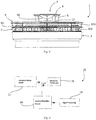
Figs. 1, 2 , and3 are top perspective, top plan and side views respectively of an optical alarm device; -
Fig. 4 is a block diagram of the main functional parts of the device; -
Fig. 5 is a cut-away perspective view showing the device housing, and Ultrasonic ("US") wave guide element pathways for US waves for obstacle detection, especially in relation to vents for ambient air entry; -
Fig. 6 is a cut-away perspective view of an ultrasonic transducer, andFig. 7 is a perspective view of its mounting PCB in which the transducer is mounted in a manner to minimise transfer of vibration to the PCB and to other components; -
Figs. 8 to 11 are diagrams illustrating operation of the obstacle detector in terms of emission of ultrasonic waves; -
Figs. 12, 13 and14 are perspective, side and cut-away views of an alternative alarm device with an obstacle detector; and -
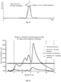
Fig. 15 is a table of data from eight consecutive scans, each with 38 sample points captured in still air, for air turbulence detection,Fig. 16 is a plot of the eight scans overlaid using the data fromFig. 15 ,Fig. 17 is a table of values including processed values,Fig. 18 is a plot showing by interrupted lines the differences in plots of amplitude vs. time where conditions are unstable in terms of air turbulence, andFig. 19 is a plot of variance across multiple sample points for stable air variance, stable air average variance, unstable air, and unstable air average variance. - Referring to
Figs. 1 to 3 analarm device 1 comprises a housing having an overall cylindrical shape with a longitudinal axis, and with abase 2 andvents 3 arranged circumferentially around a top part of the device. In this specification the term "top" means the end opposed to the mounting base, even though the device may in practice be mounted on a ceiling with the "top" facing downwardly. - The
device 1 includes an obstacle detector having an ultrasonic ("US") transceiver or "transducer" mounted on a circuit board to emit US waves, which are routed by aguide 4 havingpillars 5 supporting a dish-shaped guide element 6. Theguide element 6 is mounted centrally around the longitudinal axis of the device. It has curved lower (first) and upper (second)surfaces lower surface 10 faces thedevice body 2, and a generallyconvex surface 11 faces away from thedevice body 2. Theconcave surface 10 faces a top generally convexsurface 12 of thehousing 2 facing theguide element 6. - The invention is not concerned with the sensing details as they can be of any known type for detecting heat, smoke, or gas which enters the
vents 3. In this case the active sensor is a smoke detector with an optical chamber. - As best shown in
Figs. 1 ,3 , and5 thevents 3 comprise a ring of circumferentially arranged radial vents 3(a) and, immediately above, a ring of vents 3(b) which are sloped to have a directional component facing radially and a directional component facing axially (parallel to the longitudinal axis). There is arim 9 over thevents 3, in the form of a ring mounted onpillars 13, spaced apart from thevents 3. In this specification the term axial is intended to mean parallel to the longitudinal axis, which inFig. 3 is a central vertical line through the centre of thedevice 1. - Referring specifically to
Figs. 4 and5 thedevice 1 has anultrasonic transducer 16 driven by adriver circuit 17, and is connected to areceiver amplifier circuit 18, in turn connected to asignal processing circuit 15 for delivery of signals to a microprocessor (not shown). In this case the microprocessor is a low power, 8-bit processor. - As shown in
Figs. 5 to 7 theUS transducer 16 has acap 21 housing the active piezo element and being surrounded by a vibration isolator in the form of arubber sleeve 23 which protrudes downwardly to provide aninternal space 25 for flexible leads 26. Theisolator 23 has acircumferential groove 27 near its lower end, thegroove 27 having a width matching the thickness of a mountingPCB 22. Thetransducer 16 is mounted in ahole 24 of thePCB 22, with the edge of thehole 24 engaging in thegroove 27 of therubber isolator casing 23. - As best shown in
Fig. 5 , the surface of theUS transducer 16 is substantially co-planar with thehousing surface 12, and this provides for the US waves to be generated at or near the external surface of thehousing device body 12. The US waves therefore do not interfere with internal components within the device body, and advantageously the transmission and reception of US waves have clear paths from the on-axis transducer location and reflected from theguide element 6. - A major advantage of placing the
transducer 16 surface substantially flush with thehousing surface 12 instead of inside the housing, is that it minimises echo signals caused by the ultrasound waves reflecting off the internal details of the housing. These unwanted signals could cause false detections of objects due to the housing itself and could be randomly increased if turbulent warm air passing through the housing refracts the ultrasound in such a way that more of the sound energy is reflected back to the transducer than during static airflow conditions. - Also, the mounting arrangement minimises vibration from the US transducer to the
PCB 22 by virtue of damping by thesleeve 23. Also, the flexible electrical connector leads 26 provide electrical connection to a terminal 28 mounted on the lower surface of thePCB 22. This further ensures that mechanical vibration is not transmitted to the PCB. This has the effect of reducing signal "ringing" while also reducing stress on electrical joint components, helping to ensure reliability. "Ringing" is a known condition of US transducers, where the generated oscillations continue even after the excitation source has been removed. For detection of near-field objects, ringing should be reduced such that it does not interact with the returning echo signal of interest. For a near object to be correctly detected, the ringing is preferably therefore stopped as soon as possible after excitation. - The
guide element 6, being placed so close to the US source 16 (less than 5 mm) acts as a secondary ultrasonic source upon ultrasonic waves being incident on thefirst surface 10. This aspect is assisted by theguide element 6 having a thickness of only about 2.8mm, being located just less than 5mm at its closest from theultrasonic source 16, and being of moulded plastics material (polycarbonate). - The
top surface 11 generally has an overall taper extending proximally towards thehousing 12 and radially inwardly to the longitudinal axis (centrally and downwardly as viewed inFig. 3 for example), and as noted above has locally between its rim and the centre (longitudinal axis) a slight convex shape as viewed in section. The slight convex shape is not essential, but it is preferred that theelement 6 has an overall dish shape tapered distally from thehousing 12 and radially from the longitudinal axis (upwardly and outwardly as viewed in for exampleFig. 3 ). Thelower surface 10 is also tapered generally proximally and radially towards the housing at the longitudinal axis (downwardly and inwardly as viewed for example inFig. 3 ). Locally between the element rim and the longitudinal axis thesurface 10 has a slight concave shape as viewed in section, but again this is not essential. Again, the overall guide element configuration is dish-shaped. - Use of the obstacle detector is now described with reference to
Figs. 5 and8 to 11 , which are diagrammatic views illustrating paths of US waves emitted by thetransducer 16. Advantageously, the US waves propagate radially from the longitudinal axis of the device, out from a space between theguide element 6lower surface 10 and thehousing 2top surface 12. This wave propagation path includes above and below therim 9 and through the vents 3(a) and 3(b). Blockage or taping of either the axial or radial vents creates a new surface off which the outgoing US wave can strike, resulting in an echo that is measurable, thereby detecting blockages. This detects for example taping over the vents (which may be inadvertently left in place by a decorator). Also, as shown inFigs. 11 (a) and 11(b) such waves will encounter an obstacle Y parallel with the longitudinal axis, in this case vertical. Upon encountering an obstacle, the waves are reflected back much more quickly than if there were no obstacle. Thetransducer 16 operates with thereceiver amplifier circuit 18 to detect such early reflections in a manner which is well known per se in the art. - The "field of view" for the
single transducer 16 therefore includes all radial directions from the device longitudinal axis, allowing detection of obstacles both on the device itself (such as tape) or nearby. - Moreover, the
guide element 6 also acts as a secondary US wave source due to its vibration in response to the waves which are incident on itslower surface 10 facing thetransducer 16. This is primarily due to the short distance between theUS transducer 16 and the guide element 6 (less than 5mm at its closest, and preferably in the range of 1.5mm to 4mm) and it is also helped by the fact that the guide element is thin enough to vibrate. In this case the thickness of the element is about 2.8mm and it is of plastics (polycarbonate) composition, thereby allowing it to vibrate. - This causes US waves to propagate axially from the device, as shown in
Figs. 9 to 11 . This allows further extension of the field of view, allowing the obstacle detector to detect horizontal obstacles X such as shown inFigs. 10(a) and 10(b) . The returning echo signal (Fig. 10(b) ) encounters theguide element 6 upon which the vibration is re-transmitted back to theUS transducer 16 for detection. The return signal is further enhanced from horizontal obstacles X by way of the angled edge of theouter rim 9 and/or angled vent fins. - Another advantageous aspect of the
device 1 is that by providing vents which face radially and also vents which at least partially face axially there is less chance of all of the vents being accidently taped. This is further improved by virtue of therim 9, which acts as a spaced-apart barrier to help reduce chances of the vents being taped over such that air entry is completely blocked or blocked to an extent that severely hinders the operation of the alarm. - With the
rim 9 effectively preventing convenient access to the radial and axial vents, tape applied around the circumference of the unit is no longer sufficient to block some or all of the vents from air entry, since there still remains a viable air entry path in the axial direction. - Referring to
Figs. 12 to 14 analternative device 100 has ahousing 102 with aguide 104 akin to theguide 4 ofFigs. 1 to 13 . In this case there arevents 103 which face both radially and axially.Spacers 130 are arranged to extend generally axially between thevents 103, thereby helping to prevent taping of thevents 103 while also allowing propagation of US waves through and over the vents. - Another advantageous aspect of the device is that the processor is programmed to detect ambient air changes and turbulence, thereby providing an indication of reliability of the US obstacle detection measurement. An obstacle detection test may be inaccurate if the ambient air is unstable, for example by flowing at an excessive flow rate, and/or rapid changes in air temperature (relative to the steady state temperature of the unit or object under test), by for example a nearby air conditioning unit. Such air flow may render the obstacle detection inaccurate because the relevant changes in air characteristics (temperature, velocity, refractive index) would affect US beam uniformity, signal intensity and propagation time to and from the obstacle. This makes accurate US detection of objects, and also calculation of object distance from echo return time, unreliable.
- In this embodiment the air stability test is integrated with the obstacle detection test, the processor firstly analysing the US return signal values to initially determine if the ambient air is sufficiently stable. If sufficiently stable, the processor proceeds to use the values to determine if there is an obstacle.
- It is also envisaged that the processor may carry out an air stability test as a discrete test to decide whether to carry out an obstacle detection test. For example, the processor may be programmed to carry out an obstacle detection routine once per day, thereby consuming valuable electrical power only for a number of seconds once per day.
- For each obstacle detection test the processor performs a number of ultrasonic scans separated by a small (about 1msec) delay. To reduce the effect of signal noise, the results of the scans are summed and averaged to a single data set upon which obstacle detection logic is performed. Since averaging requires multiple scans, the system uses these multiple scans more advantageously to determine the ambient air stability, thus acting as an indicator of reliability for obstacle detection measurements.
- In each scan, the US transducer is driven with a number of pulses, after which the processor samples and stores the amplitude of the returning signal as a function of time. The processor then performs calculations to quantify the extent of amplitude variation between the same sample points on successive scans. Variance or Standard Deviation across all scans is then calculated for each data point.
- It is useful to, for example, sum or average the variance, or standard deviation values to yield a single value for the entire scan. This value is compared to a threshold to determine if the ambient air properties were stable or unstable during the time of the scans.
- In stable air conditions the variation from measurement to measurement should be small across the full scan, yielding a low average variance value. As instability in the air increases the variance increases. The threshold level is determined empirically, based on acceptable limits of detection and repeatability of the system.
- If the result of the calculation is less than the threshold, the scan is "Stable" and so the average scan is accepted as a valid obstacle detection measurement. If the result is "Unstable", the obstacle detection measurement is not accepted and the measurement should be repeated. This may be repeated at intervals until a valid ("Stable") measurement is obtained.
-
Fig. 15 is a table of return signal amplitude values for 6 of the 36 sample points in 8 scans. Each column is a scan and each row contains the return values for a certain sample point across all of the scans. For example,Row 3 of theFig. 15 table shows the return signal amplitude values for the first sample point for all 8 scans. - Referring to
Fig. 16 variations in amplitude of the return signals is shown. - To determine the level of variability, the processor measures the absolute difference (or 'delta' in reference to
Fig. 15 ) between a particular sample point return signal value of one scan and the next, comparing each scan to the previous, for all 8 scans (in this case). There may be one column for each delta value across the 8 scans, so therefore 7 columns of delta values, as shown inFig. 17 . The right-hand column ofFig. 17 has the value for the sum of the deltas for each row (i.e. the sum of the seven-delta series of values for each sample point). -
Fig. 18 shows examples of amplitude signals for stable and unstable conditions. The higher and lower amplitudes shown for the unstable condition indicate how the signal can vary relative to the true signal (stable condition) as a result of air instability, caused by, for example, an air-conditioning blower. In this case the amplitude variability occurs rapidly (for example, less than 1 sec), so fast successive scans can therefore measure these variances. This is in contrast to other environmental instability such as room temperature changes which generally occur over minutes or hours and would generally have little effect on the amplitude of the return signal (but may change the echo return time if compensation for temperature is not included). - Unwanted amplitude variation of a signal is effectively noise, and an alternative approach may be to minimize such noise by averaging the signals. However, if the variation in amplitude is a significant fraction of the true amplitude, then the average signal may be a poor representation of the actual signal. This is especially true if the number of scans or samples is limited by hardware, power consumption or memory, such as with inexpensive 8-bit microcontrollers. Experimentally it was found that averaging of 16 times was insufficient to remove the noise caused by air instability from air conditioning unit and could lead to false detections or misinterpretation of the signals. Hence, the approach of determining and analysing variance is preferred.
-
Fig. 19 shows the values of variance represented by arbitrary units. The average variance for stable air is approximately 2 units and that for unstable air is about 10 units. These units allow the processor to have a threshold setting for average variance above which it decides that the air is excessively unstable. - The following is an example of simplified pseudo code for the turbulence testing performed by the processor.
- Drive transducer with x number of pulses.
- Start sampling via ADC.
- Take 40 samples with time interval of 50µsec (total time of sampling is therefore 2 msec per scan).
- Store samples in array.
- Wait 5 msecs.
- Repeat the
above procedure 16 times to yield an array of 16 x 40 samples. - For each sample point, calculate the absolute difference between each point on successive scans.
- Sum the 16 absolute difference values to yield a single value for each of the 40 sample points. The resulting array is 1 x 40.
- This array can be averaged by dividing each value by 16 or used as is.
- The resulting array can be further simplified to a single value by averaging all samples into one, i.e. sum the 40 sample points and divide by 40.
- This "turbulence" value gives an indication of the average absolute difference across all sample points.
- This single value is compared to an "instability threshold".
- If "turbulence" value > "instability threshold" raise flag to alert system or user, abort obstacle detection.
- If "turbulence" value < "instability threshold", proceed to process the previously stored 16-scan data for purposes of obstacle detection.
- The invention is not limited to the embodiments described but may be varied in construction and detail. For example, even though the US guide provides a wide field of view for the single transducer there may be one or more additional transducers. It is not essential that the top surface or the bottom surface of the guide element be curved as viewed in a plane from the longitudinal axis towards the edge, and if either is curved the shape may be convex or concave between the longitudinal axis and the edge.
Claims (15)
- An alarm device to detect a condition of ambient air, the alarm device comprising:a housing (2) having a longitudinal axis and containing a sensor and having vents (3) for access by ambient air to the sensor,a signal processing circuit (15) with a processor linked with the sensor,a power supply for the circuit and the sensor,an obstacle detector for detecting presence of an unwanted obstacle to flow of ambient air to said sensor, the obstacle detector comprising:an ultrasonic transducer (16) mounted in or on the device to have a field of emission outside of the device,a processor (18, 19) in the circuit (22) and linked with the ultrasonic transducer to monitor ultrasonic return values and process them to determine if any have been reflected by an unwanted obstacle, wherein the processor is configured to generate an alert to indicate presence of such an obstacle which may affect access of ambient air to the sensor through the vents, anda guide (4) mounted to the housing to reflect emitted ultrasonic waves in radial directions relative to the longitudinal axis.
- An alarm device as claimed in claim 1, wherein the guide comprises a guide element (6) mounted to the housing (2) so that it is spaced-apart from the housing, and the guide element is dish-shaped with a narrower end facing the housing, and the housing has a curved generally convex surface (12) facing the guide element.
- An alarm device as claimed in claim 2, wherein the guide element is mounted by a plurality of pillars (5), is mounted substantially symmetrically to the device longitudinal axis, and is spaced from the ultrasonic transducer by less than 5mm.
- An alarm device as claimed in claim 3, wherein the guide element has a surface (10) facing the housing which has a concave curve from the longitudinal axis towards the edge of the guide element, and the transducer (16) has a surface which is substantially flush with the housing surface (12).
- An alarm device as claimed in any preceding claim, wherein at least some of the vents (3(b)) are arranged so that at least some ultrasonic waves pass through the vents.
- An alarm device as claimed in claim 5, wherein the vents include vents (3(a)) which are primarily facing radially and vents (3(b)) which at least have a directional component facing axially.
- An alarm device as claimed in any preceding claim, wherein the housing includes a barrier (9) to render application of tape to the vents difficult.
- An alarm device as claimed in claim 7, wherein the barrier comprises a barrier element (9) mounted by pillars (13) so that it is spaced apart from at least some vents, and optionally the barrier element is annular.
- An alarm device as claimed in claim 7, wherein the barrier comprises a plurality of elements (130) which extend from the housing between vents (103).
- An alarm device as claimed in any preceding claim, wherein the ultrasonic transducer is mounted in a resilient cover (23) and said cover engages in an aperture (24) of a substrate (22) which is in turn mounted to the housing.
- An alarm device as claimed in claim 10, wherein the resilient cover (23) has a groove (27) which engages a side edge of the substrate aperture, and wherein the ultrasonic transducer is connected to a conductor (28) on a substrate by a flexible wire link (26).
- An alarm device as claimed in any preceding claim, wherein the processor (18, 19) is programmed to detect ambient air instability either before or as part of an obstacle detection operation, and wherein the processor is configured to record a return signal amplitude value for each of a plurality of sample points, and to quantify variance across said values, and if said variance exceeds a threshold determine that there is excessive ambient air instability.
- An alarm device as claimed in any claim 12, wherein the processor (18, 19) is configured to determine a series of difference values for each pair of successive values for a sample point, and to derive a sample point variance value representative of variance for each sample point, and to compare the derived sample point variance value with a threshold.
- An alarm device as claimed in claim 13, wherein the derived sample point variance value is a sum of the difference values for a sample point.
- An alarm device as claimed in any of claims 12 or 14, wherein the processor (18, 19) is configured to perform a plurality of scans each with a plurality of sample points, and to determine a multi-scan derived variance value derived from said sample point variance values, and wherein a multi-scan derived variance value is an average of all sample point variance values.
Priority Applications (3)
| Application Number | Priority Date | Filing Date | Title |
|---|---|---|---|
| EP24159784.8A EP4354410A3 (en) | 2019-04-02 | 2020-03-11 | Ultrasonic obstacle detection in alarm devices |
| EP24159781.4A EP4350655B1 (en) | 2019-04-02 | 2020-03-11 | Ultrasonic obstacle detection in alarm devices |
| EP22212653.4A EP4177860A1 (en) | 2019-04-02 | 2020-03-11 | Ultrasonic obstacle detection in alarm devices |
Applications Claiming Priority (2)
| Application Number | Priority Date | Filing Date | Title |
|---|---|---|---|
| EP19166739 | 2019-04-02 | ||
| EP19166743 | 2019-04-02 |
Related Child Applications (4)
| Application Number | Title | Priority Date | Filing Date |
|---|---|---|---|
| EP24159784.8A Division EP4354410A3 (en) | 2019-04-02 | 2020-03-11 | Ultrasonic obstacle detection in alarm devices |
| EP22212653.4A Division-Into EP4177860A1 (en) | 2019-04-02 | 2020-03-11 | Ultrasonic obstacle detection in alarm devices |
| EP22212653.4A Division EP4177860A1 (en) | 2019-04-02 | 2020-03-11 | Ultrasonic obstacle detection in alarm devices |
| EP24159781.4A Division EP4350655B1 (en) | 2019-04-02 | 2020-03-11 | Ultrasonic obstacle detection in alarm devices |
Publications (2)
| Publication Number | Publication Date |
|---|---|
| EP3719768A1 true EP3719768A1 (en) | 2020-10-07 |
| EP3719768B1 EP3719768B1 (en) | 2023-01-18 |
Family
ID=69804730
Family Applications (6)
| Application Number | Title | Priority Date | Filing Date |
|---|---|---|---|
| EP20162532.4A Active EP3719768B1 (en) | 2019-04-02 | 2020-03-11 | Ultrasonic obstacle detection in alarm devices |
| EP22212657.5A Active EP4174812B1 (en) | 2019-04-02 | 2020-03-11 | Ultrasonic detectors |
| EP24159784.8A Pending EP4354410A3 (en) | 2019-04-02 | 2020-03-11 | Ultrasonic obstacle detection in alarm devices |
| EP20162537.3A Active EP3719769B1 (en) | 2019-04-02 | 2020-03-11 | Sensing device |
| EP24159781.4A Active EP4350655B1 (en) | 2019-04-02 | 2020-03-11 | Ultrasonic obstacle detection in alarm devices |
| EP22212653.4A Pending EP4177860A1 (en) | 2019-04-02 | 2020-03-11 | Ultrasonic obstacle detection in alarm devices |
Family Applications After (5)
| Application Number | Title | Priority Date | Filing Date |
|---|---|---|---|
| EP22212657.5A Active EP4174812B1 (en) | 2019-04-02 | 2020-03-11 | Ultrasonic detectors |
| EP24159784.8A Pending EP4354410A3 (en) | 2019-04-02 | 2020-03-11 | Ultrasonic obstacle detection in alarm devices |
| EP20162537.3A Active EP3719769B1 (en) | 2019-04-02 | 2020-03-11 | Sensing device |
| EP24159781.4A Active EP4350655B1 (en) | 2019-04-02 | 2020-03-11 | Ultrasonic obstacle detection in alarm devices |
| EP22212653.4A Pending EP4177860A1 (en) | 2019-04-02 | 2020-03-11 | Ultrasonic obstacle detection in alarm devices |
Country Status (1)
| Country | Link |
|---|---|
| EP (6) | EP3719768B1 (en) |
Cited By (1)
| Publication number | Priority date | Publication date | Assignee | Title |
|---|---|---|---|---|
| CN115683967A (en) * | 2022-11-08 | 2023-02-03 | 赛特威尔电子股份有限公司 | Alarm with obstacle detection function |
Families Citing this family (1)
| Publication number | Priority date | Publication date | Assignee | Title |
|---|---|---|---|---|
| DE102023203881A1 (en) * | 2023-04-26 | 2024-10-31 | Hekatron Vertriebs Gmbh | Fire detector and monitoring device |
Citations (4)
| Publication number | Priority date | Publication date | Assignee | Title |
|---|---|---|---|---|
| US20090243843A1 (en) * | 2008-03-26 | 2009-10-01 | Honeywell International Inc. | Apparatus and method of blockage detection |
| EP2348495A1 (en) * | 2009-12-04 | 2011-07-27 | Atral-Secal GmbH | Smoke alarm with ultrasound coverage monitoring |
| EP2492882A1 (en) | 2011-02-28 | 2012-08-29 | Hager Controls | Device for detecting obstacles concealing a smoke detector |
| US20150145684A1 (en) * | 2013-11-27 | 2015-05-28 | Siemens Schweiz Ag | Auxiliary device for a hazard alarm constructed as a point type detector for function monitoring of the hazard alarm, and an arrangement and method of monitoring using a device of this kind |
Family Cites Families (3)
| Publication number | Priority date | Publication date | Assignee | Title |
|---|---|---|---|---|
| US4975688A (en) * | 1988-09-22 | 1990-12-04 | Gonzales Ronald A | Particulate detector disabling and protecting system |
| US5339072A (en) * | 1991-12-09 | 1994-08-16 | Nohmi Bosai, Ltd | Fire detector with anti-tampering measures for use in vehicles |
| CN201524292U (en) | 2009-11-15 | 2010-07-14 | 陈培杰 | Amniotic fluid suction device specially used for obstetrics and gynecology |
-
2020
- 2020-03-11 EP EP20162532.4A patent/EP3719768B1/en active Active
- 2020-03-11 EP EP22212657.5A patent/EP4174812B1/en active Active
- 2020-03-11 EP EP24159784.8A patent/EP4354410A3/en active Pending
- 2020-03-11 EP EP20162537.3A patent/EP3719769B1/en active Active
- 2020-03-11 EP EP24159781.4A patent/EP4350655B1/en active Active
- 2020-03-11 EP EP22212653.4A patent/EP4177860A1/en active Pending
Patent Citations (4)
| Publication number | Priority date | Publication date | Assignee | Title |
|---|---|---|---|---|
| US20090243843A1 (en) * | 2008-03-26 | 2009-10-01 | Honeywell International Inc. | Apparatus and method of blockage detection |
| EP2348495A1 (en) * | 2009-12-04 | 2011-07-27 | Atral-Secal GmbH | Smoke alarm with ultrasound coverage monitoring |
| EP2492882A1 (en) | 2011-02-28 | 2012-08-29 | Hager Controls | Device for detecting obstacles concealing a smoke detector |
| US20150145684A1 (en) * | 2013-11-27 | 2015-05-28 | Siemens Schweiz Ag | Auxiliary device for a hazard alarm constructed as a point type detector for function monitoring of the hazard alarm, and an arrangement and method of monitoring using a device of this kind |
Cited By (2)
| Publication number | Priority date | Publication date | Assignee | Title |
|---|---|---|---|---|
| CN115683967A (en) * | 2022-11-08 | 2023-02-03 | 赛特威尔电子股份有限公司 | Alarm with obstacle detection function |
| WO2024098536A1 (en) * | 2022-11-08 | 2024-05-16 | 赛特威尔电子股份有限公司 | Alarm with obstacle detection function |
Also Published As
| Publication number | Publication date |
|---|---|
| EP4350655C0 (en) | 2026-04-01 |
| EP3719768B1 (en) | 2023-01-18 |
| EP3719769A1 (en) | 2020-10-07 |
| EP4350655A3 (en) | 2024-07-10 |
| EP4174812A1 (en) | 2023-05-03 |
| EP4350655A2 (en) | 2024-04-10 |
| EP4350655B1 (en) | 2026-04-01 |
| EP3719769B1 (en) | 2023-01-18 |
| EP4354410A3 (en) | 2024-07-24 |
| EP4354410A2 (en) | 2024-04-17 |
| EP4177860A1 (en) | 2023-05-10 |
| EP4174812B1 (en) | 2024-07-03 |
| EP4174812C0 (en) | 2024-07-03 |
Similar Documents
| Publication | Publication Date | Title |
|---|---|---|
| CN208818300U (en) | Level and surface temperature gauge table | |
| US7685861B2 (en) | Method and apparatus for calibrating an ultrasonic sensing system used to detect moving objects | |
| EP4350655B1 (en) | Ultrasonic obstacle detection in alarm devices | |
| US5119676A (en) | Ultrasonic method and apparatus for determining water level in a closed vessel | |
| CN1324449A (en) | Device for carrying out measurement in the ear | |
| US6584860B1 (en) | Flow probe insertion gauge | |
| CN109154521A (en) | Ultrasonic liquid level sensor with reflector | |
| EP2729794B1 (en) | Device for the non-destructive inspection of a test object by means of ultrasound, method for operating such a device and method for the non-destructive inspection of a test object by means of ultrasound | |
| CN101300611A (en) | Combined scattered light and extinction fire alarm | |
| CA2908682A1 (en) | Conical ultrasonic probe | |
| KR101665786B1 (en) | Method and apparatus for measuring a distance using ultrasonic waves | |
| JP2000105115A (en) | Ultrasonic object detector and ultrasonic ice storage detector | |
| JP2008530559A (en) | Ultrasonic beam forming device | |
| WO2002093156A3 (en) | Non-destructive ultrasound test method for detection of damage and device for carrying out the same | |
| JP3296804B2 (en) | Obstacle judgment method | |
| CN208872874U (en) | A kind of sitting posture detection device and desk lamp | |
| JP2609647B2 (en) | Ultrasonic flaw detector | |
| EP3811053B1 (en) | Laser sensor module for measuring particle density of particles comprising detector arranged to provide an indication signal of soiling of emission window, method and computer program product | |
| CN208872873U (en) | A kind of sitting posture detection device and desk lamp | |
| JPH0850177A (en) | Ultrasonic distance measuring device | |
| JP2843265B2 (en) | Photoelectric smoke detector | |
| WO2024098536A1 (en) | Alarm with obstacle detection function | |
| RU2791163C1 (en) | Method for detecting probing signals | |
| JP3453236B2 (en) | Ultrasonic thickness gauge with prohibition gate | |
| JPH0278949A (en) | Ultrasonic flaw detecting device |
Legal Events
| Date | Code | Title | Description |
|---|---|---|---|
| PUAI | Public reference made under article 153(3) epc to a published international application that has entered the european phase |
Free format text: ORIGINAL CODE: 0009012 |
|
| STAA | Information on the status of an ep patent application or granted ep patent |
Free format text: STATUS: THE APPLICATION HAS BEEN PUBLISHED |
|
| AK | Designated contracting states |
Kind code of ref document: A1 Designated state(s): AL AT BE BG CH CY CZ DE DK EE ES FI FR GB GR HR HU IE IS IT LI LT LU LV MC MK MT NL NO PL PT RO RS SE SI SK SM TR |
|
| AX | Request for extension of the european patent |
Extension state: BA ME |
|
| STAA | Information on the status of an ep patent application or granted ep patent |
Free format text: STATUS: REQUEST FOR EXAMINATION WAS MADE |
|
| 17P | Request for examination filed |
Effective date: 20210401 |
|
| RBV | Designated contracting states (corrected) |
Designated state(s): AL AT BE BG CH CY CZ DE DK EE ES FI FR GB GR HR HU IE IS IT LI LT LU LV MC MK MT NL NO PL PT RO RS SE SI SK SM TR |
|
| GRAP | Despatch of communication of intention to grant a patent |
Free format text: ORIGINAL CODE: EPIDOSNIGR1 |
|
| STAA | Information on the status of an ep patent application or granted ep patent |
Free format text: STATUS: GRANT OF PATENT IS INTENDED |
|
| INTG | Intention to grant announced |
Effective date: 20220913 |
|
| GRAS | Grant fee paid |
Free format text: ORIGINAL CODE: EPIDOSNIGR3 |
|
| GRAA | (expected) grant |
Free format text: ORIGINAL CODE: 0009210 |
|
| STAA | Information on the status of an ep patent application or granted ep patent |
Free format text: STATUS: THE PATENT HAS BEEN GRANTED |
|
| AK | Designated contracting states |
Kind code of ref document: B1 Designated state(s): AL AT BE BG CH CY CZ DE DK EE ES FI FR GB GR HR HU IE IS IT LI LT LU LV MC MK MT NL NO PL PT RO RS SE SI SK SM TR |
|
| REG | Reference to a national code |
Ref country code: GB Ref legal event code: FG4D |
|
| REG | Reference to a national code |
Ref country code: DE Ref legal event code: R096 Ref document number: 602020007599 Country of ref document: DE |
|
| REG | Reference to a national code |
Ref country code: CH Ref legal event code: EP |
|
| REG | Reference to a national code |
Ref country code: AT Ref legal event code: REF Ref document number: 1545117 Country of ref document: AT Kind code of ref document: T Effective date: 20230215 Ref country code: IE Ref legal event code: FG4D |
|
| REG | Reference to a national code |
Ref country code: LT Ref legal event code: MG9D |
|
| REG | Reference to a national code |
Ref country code: NL Ref legal event code: MP Effective date: 20230118 |
|
| P01 | Opt-out of the competence of the unified patent court (upc) registered |
Effective date: 20230420 |
|
| REG | Reference to a national code |
Ref country code: AT Ref legal event code: MK05 Ref document number: 1545117 Country of ref document: AT Kind code of ref document: T Effective date: 20230118 |
|
| PG25 | Lapsed in a contracting state [announced via postgrant information from national office to epo] |
Ref country code: NL Free format text: LAPSE BECAUSE OF FAILURE TO SUBMIT A TRANSLATION OF THE DESCRIPTION OR TO PAY THE FEE WITHIN THE PRESCRIBED TIME-LIMIT Effective date: 20230118 |
|
| PG25 | Lapsed in a contracting state [announced via postgrant information from national office to epo] |
Ref country code: RS Free format text: LAPSE BECAUSE OF FAILURE TO SUBMIT A TRANSLATION OF THE DESCRIPTION OR TO PAY THE FEE WITHIN THE PRESCRIBED TIME-LIMIT Effective date: 20230118 Ref country code: PT Free format text: LAPSE BECAUSE OF FAILURE TO SUBMIT A TRANSLATION OF THE DESCRIPTION OR TO PAY THE FEE WITHIN THE PRESCRIBED TIME-LIMIT Effective date: 20230518 Ref country code: NO Free format text: LAPSE BECAUSE OF FAILURE TO SUBMIT A TRANSLATION OF THE DESCRIPTION OR TO PAY THE FEE WITHIN THE PRESCRIBED TIME-LIMIT Effective date: 20230418 Ref country code: LV Free format text: LAPSE BECAUSE OF FAILURE TO SUBMIT A TRANSLATION OF THE DESCRIPTION OR TO PAY THE FEE WITHIN THE PRESCRIBED TIME-LIMIT Effective date: 20230118 Ref country code: LT Free format text: LAPSE BECAUSE OF FAILURE TO SUBMIT A TRANSLATION OF THE DESCRIPTION OR TO PAY THE FEE WITHIN THE PRESCRIBED TIME-LIMIT Effective date: 20230118 Ref country code: HR Free format text: LAPSE BECAUSE OF FAILURE TO SUBMIT A TRANSLATION OF THE DESCRIPTION OR TO PAY THE FEE WITHIN THE PRESCRIBED TIME-LIMIT Effective date: 20230118 Ref country code: ES Free format text: LAPSE BECAUSE OF FAILURE TO SUBMIT A TRANSLATION OF THE DESCRIPTION OR TO PAY THE FEE WITHIN THE PRESCRIBED TIME-LIMIT Effective date: 20230118 Ref country code: AT Free format text: LAPSE BECAUSE OF FAILURE TO SUBMIT A TRANSLATION OF THE DESCRIPTION OR TO PAY THE FEE WITHIN THE PRESCRIBED TIME-LIMIT Effective date: 20230118 |
|
| PG25 | Lapsed in a contracting state [announced via postgrant information from national office to epo] |
Ref country code: SE Free format text: LAPSE BECAUSE OF FAILURE TO SUBMIT A TRANSLATION OF THE DESCRIPTION OR TO PAY THE FEE WITHIN THE PRESCRIBED TIME-LIMIT Effective date: 20230118 Ref country code: PL Free format text: LAPSE BECAUSE OF FAILURE TO SUBMIT A TRANSLATION OF THE DESCRIPTION OR TO PAY THE FEE WITHIN THE PRESCRIBED TIME-LIMIT Effective date: 20230118 Ref country code: IS Free format text: LAPSE BECAUSE OF FAILURE TO SUBMIT A TRANSLATION OF THE DESCRIPTION OR TO PAY THE FEE WITHIN THE PRESCRIBED TIME-LIMIT Effective date: 20230518 Ref country code: GR Free format text: LAPSE BECAUSE OF FAILURE TO SUBMIT A TRANSLATION OF THE DESCRIPTION OR TO PAY THE FEE WITHIN THE PRESCRIBED TIME-LIMIT Effective date: 20230419 Ref country code: FI Free format text: LAPSE BECAUSE OF FAILURE TO SUBMIT A TRANSLATION OF THE DESCRIPTION OR TO PAY THE FEE WITHIN THE PRESCRIBED TIME-LIMIT Effective date: 20230118 |
|
| REG | Reference to a national code |
Ref country code: DE Ref legal event code: R097 Ref document number: 602020007599 Country of ref document: DE |
|
| PG25 | Lapsed in a contracting state [announced via postgrant information from national office to epo] |
Ref country code: SM Free format text: LAPSE BECAUSE OF FAILURE TO SUBMIT A TRANSLATION OF THE DESCRIPTION OR TO PAY THE FEE WITHIN THE PRESCRIBED TIME-LIMIT Effective date: 20230118 Ref country code: RO Free format text: LAPSE BECAUSE OF FAILURE TO SUBMIT A TRANSLATION OF THE DESCRIPTION OR TO PAY THE FEE WITHIN THE PRESCRIBED TIME-LIMIT Effective date: 20230118 Ref country code: MC Free format text: LAPSE BECAUSE OF FAILURE TO SUBMIT A TRANSLATION OF THE DESCRIPTION OR TO PAY THE FEE WITHIN THE PRESCRIBED TIME-LIMIT Effective date: 20230118 Ref country code: EE Free format text: LAPSE BECAUSE OF FAILURE TO SUBMIT A TRANSLATION OF THE DESCRIPTION OR TO PAY THE FEE WITHIN THE PRESCRIBED TIME-LIMIT Effective date: 20230118 Ref country code: DK Free format text: LAPSE BECAUSE OF FAILURE TO SUBMIT A TRANSLATION OF THE DESCRIPTION OR TO PAY THE FEE WITHIN THE PRESCRIBED TIME-LIMIT Effective date: 20230118 Ref country code: CZ Free format text: LAPSE BECAUSE OF FAILURE TO SUBMIT A TRANSLATION OF THE DESCRIPTION OR TO PAY THE FEE WITHIN THE PRESCRIBED TIME-LIMIT Effective date: 20230118 |
|
| REG | Reference to a national code |
Ref country code: CH Ref legal event code: PL |
|
| PLBE | No opposition filed within time limit |
Free format text: ORIGINAL CODE: 0009261 |
|
| STAA | Information on the status of an ep patent application or granted ep patent |
Free format text: STATUS: NO OPPOSITION FILED WITHIN TIME LIMIT |
|
| PG25 | Lapsed in a contracting state [announced via postgrant information from national office to epo] |
Ref country code: SK Free format text: LAPSE BECAUSE OF FAILURE TO SUBMIT A TRANSLATION OF THE DESCRIPTION OR TO PAY THE FEE WITHIN THE PRESCRIBED TIME-LIMIT Effective date: 20230118 |
|
| REG | Reference to a national code |
Ref country code: BE Ref legal event code: MM Effective date: 20230331 |
|
| 26N | No opposition filed |
Effective date: 20231019 |
|
| PG25 | Lapsed in a contracting state [announced via postgrant information from national office to epo] |
Ref country code: LU Free format text: LAPSE BECAUSE OF NON-PAYMENT OF DUE FEES Effective date: 20230311 |
|
| PG25 | Lapsed in a contracting state [announced via postgrant information from national office to epo] |
Ref country code: SI Free format text: LAPSE BECAUSE OF FAILURE TO SUBMIT A TRANSLATION OF THE DESCRIPTION OR TO PAY THE FEE WITHIN THE PRESCRIBED TIME-LIMIT Effective date: 20230118 Ref country code: LI Free format text: LAPSE BECAUSE OF NON-PAYMENT OF DUE FEES Effective date: 20230331 Ref country code: CH Free format text: LAPSE BECAUSE OF NON-PAYMENT OF DUE FEES Effective date: 20230331 |
|
| PG25 | Lapsed in a contracting state [announced via postgrant information from national office to epo] |
Ref country code: BE Free format text: LAPSE BECAUSE OF NON-PAYMENT OF DUE FEES Effective date: 20230331 |
|
| PG25 | Lapsed in a contracting state [announced via postgrant information from national office to epo] |
Ref country code: IT Free format text: LAPSE BECAUSE OF FAILURE TO SUBMIT A TRANSLATION OF THE DESCRIPTION OR TO PAY THE FEE WITHIN THE PRESCRIBED TIME-LIMIT Effective date: 20230118 |
|
| PG25 | Lapsed in a contracting state [announced via postgrant information from national office to epo] |
Ref country code: BG Free format text: LAPSE BECAUSE OF FAILURE TO SUBMIT A TRANSLATION OF THE DESCRIPTION OR TO PAY THE FEE WITHIN THE PRESCRIBED TIME-LIMIT Effective date: 20230118 |
|
| PG25 | Lapsed in a contracting state [announced via postgrant information from national office to epo] |
Ref country code: BG Free format text: LAPSE BECAUSE OF FAILURE TO SUBMIT A TRANSLATION OF THE DESCRIPTION OR TO PAY THE FEE WITHIN THE PRESCRIBED TIME-LIMIT Effective date: 20230118 |
|
| PG25 | Lapsed in a contracting state [announced via postgrant information from national office to epo] |
Ref country code: CY Free format text: LAPSE BECAUSE OF FAILURE TO SUBMIT A TRANSLATION OF THE DESCRIPTION OR TO PAY THE FEE WITHIN THE PRESCRIBED TIME-LIMIT; INVALID AB INITIO Effective date: 20200311 |
|
| PG25 | Lapsed in a contracting state [announced via postgrant information from national office to epo] |
Ref country code: HU Free format text: LAPSE BECAUSE OF FAILURE TO SUBMIT A TRANSLATION OF THE DESCRIPTION OR TO PAY THE FEE WITHIN THE PRESCRIBED TIME-LIMIT; INVALID AB INITIO Effective date: 20200311 |
|
| PG25 | Lapsed in a contracting state [announced via postgrant information from national office to epo] |
Ref country code: TR Free format text: LAPSE BECAUSE OF FAILURE TO SUBMIT A TRANSLATION OF THE DESCRIPTION OR TO PAY THE FEE WITHIN THE PRESCRIBED TIME-LIMIT Effective date: 20230118 |
|
| PGFP | Annual fee paid to national office [announced via postgrant information from national office to epo] |
Ref country code: GB Payment date: 20260204 Year of fee payment: 7 |
|
| PGFP | Annual fee paid to national office [announced via postgrant information from national office to epo] |
Ref country code: DE Payment date: 20260216 Year of fee payment: 7 Ref country code: IE Payment date: 20260204 Year of fee payment: 7 |
|
| PGFP | Annual fee paid to national office [announced via postgrant information from national office to epo] |
Ref country code: FR Payment date: 20260226 Year of fee payment: 7 |