EP3719762B1 - Door unlock mechanism - Google Patents
Door unlock mechanism Download PDFInfo
- Publication number
- EP3719762B1 EP3719762B1 EP20166413.3A EP20166413A EP3719762B1 EP 3719762 B1 EP3719762 B1 EP 3719762B1 EP 20166413 A EP20166413 A EP 20166413A EP 3719762 B1 EP3719762 B1 EP 3719762B1
- Authority
- EP
- European Patent Office
- Prior art keywords
- door
- component
- keyless
- unlocking
- primary
- Prior art date
- Legal status (The legal status is an assumption and is not a legal conclusion. Google has not performed a legal analysis and makes no representation as to the accuracy of the status listed.)
- Active
Links
Images



Classifications
-
- E—FIXED CONSTRUCTIONS
- E05—LOCKS; KEYS; WINDOW OR DOOR FITTINGS; SAFES
- E05B—LOCKS; ACCESSORIES THEREFOR; HANDCUFFS
- E05B81/00—Power-actuated vehicle locks
- E05B81/54—Electrical circuits
- E05B81/90—Manual override in case of power failure
-
- G—PHYSICS
- G07—CHECKING-DEVICES
- G07C—TIME OR ATTENDANCE REGISTERS; REGISTERING OR INDICATING THE WORKING OF MACHINES; GENERATING RANDOM NUMBERS; VOTING OR LOTTERY APPARATUS; ARRANGEMENTS, SYSTEMS OR APPARATUS FOR CHECKING NOT PROVIDED FOR ELSEWHERE
- G07C9/00—Individual registration on entry or exit
- G07C9/00174—Electronically operated locks; Circuits therefor; Nonmechanical keys therefor, e.g. passive or active electrical keys or other data carriers without mechanical keys
-
- E—FIXED CONSTRUCTIONS
- E05—LOCKS; KEYS; WINDOW OR DOOR FITTINGS; SAFES
- E05B—LOCKS; ACCESSORIES THEREFOR; HANDCUFFS
- E05B77/00—Vehicle locks characterised by special functions or purposes
- E05B77/54—Automatic securing or unlocking of bolts triggered by certain vehicle parameters, e.g. exceeding a speed threshold
-
- E—FIXED CONSTRUCTIONS
- E05—LOCKS; KEYS; WINDOW OR DOOR FITTINGS; SAFES
- E05B—LOCKS; ACCESSORIES THEREFOR; HANDCUFFS
- E05B81/00—Power-actuated vehicle locks
- E05B81/02—Power-actuated vehicle locks characterised by the type of actuators used
- E05B81/04—Electrical
- E05B81/08—Electrical using electromagnets or solenoids
-
- E—FIXED CONSTRUCTIONS
- E05—LOCKS; KEYS; WINDOW OR DOOR FITTINGS; SAFES
- E05B—LOCKS; ACCESSORIES THEREFOR; HANDCUFFS
- E05B81/00—Power-actuated vehicle locks
- E05B81/24—Power-actuated vehicle locks characterised by constructional features of the actuator or the power transmission
- E05B81/32—Details of the actuator transmission
- E05B81/46—Clutches
-
- E—FIXED CONSTRUCTIONS
- E05—LOCKS; KEYS; WINDOW OR DOOR FITTINGS; SAFES
- E05B—LOCKS; ACCESSORIES THEREFOR; HANDCUFFS
- E05B81/00—Power-actuated vehicle locks
- E05B81/54—Electrical circuits
- E05B81/56—Control of actuators
-
- E—FIXED CONSTRUCTIONS
- E05—LOCKS; KEYS; WINDOW OR DOOR FITTINGS; SAFES
- E05B—LOCKS; ACCESSORIES THEREFOR; HANDCUFFS
- E05B81/00—Power-actuated vehicle locks
- E05B81/54—Electrical circuits
- E05B81/64—Monitoring or sensing, e.g. by using switches or sensors
- E05B81/76—Detection of handle operation; Detection of a user approaching a handle; Electrical switching actions performed by door handles
- E05B81/78—Detection of handle operation; Detection of a user approaching a handle; Electrical switching actions performed by door handles as part of a hands-free locking or unlocking operation
-
- E—FIXED CONSTRUCTIONS
- E05—LOCKS; KEYS; WINDOW OR DOOR FITTINGS; SAFES
- E05B—LOCKS; ACCESSORIES THEREFOR; HANDCUFFS
- E05B81/00—Power-actuated vehicle locks
- E05B81/54—Electrical circuits
- E05B81/80—Electrical circuits characterised by the power supply; Emergency power operation
-
- F—MECHANICAL ENGINEERING; LIGHTING; HEATING; WEAPONS; BLASTING
- F16—ENGINEERING ELEMENTS AND UNITS; GENERAL MEASURES FOR PRODUCING AND MAINTAINING EFFECTIVE FUNCTIONING OF MACHINES OR INSTALLATIONS; THERMAL INSULATION IN GENERAL
- F16D—COUPLINGS FOR TRANSMITTING ROTATION; CLUTCHES; BRAKES
- F16D13/00—Friction clutches
- F16D13/22—Friction clutches with axially-movable clutching members
- F16D13/24—Friction clutches with axially-movable clutching members with conical friction surfaces cone clutches
- F16D13/26—Friction clutches with axially-movable clutching members with conical friction surfaces cone clutches in which the or each axially-movable member is pressed exclusively against an axially-located member
-
- B—PERFORMING OPERATIONS; TRANSPORTING
- B60—VEHICLES IN GENERAL
- B60R—VEHICLES, VEHICLE FITTINGS, OR VEHICLE PARTS, NOT OTHERWISE PROVIDED FOR
- B60R25/00—Fittings or systems for preventing or indicating unauthorised use or theft of vehicles
- B60R25/20—Means to switch the anti-theft system on or off
- B60R25/24—Means to switch the anti-theft system on or off using electronic identifiers containing a code not memorised by the user
-
- E—FIXED CONSTRUCTIONS
- E05—LOCKS; KEYS; WINDOW OR DOOR FITTINGS; SAFES
- E05B—LOCKS; ACCESSORIES THEREFOR; HANDCUFFS
- E05B77/00—Vehicle locks characterised by special functions or purposes
- E05B77/02—Vehicle locks characterised by special functions or purposes for accident situations
-
- E—FIXED CONSTRUCTIONS
- E05—LOCKS; KEYS; WINDOW OR DOOR FITTINGS; SAFES
- E05Y—INDEXING SCHEME ASSOCIATED WITH SUBCLASSES E05D AND E05F, RELATING TO CONSTRUCTION ELEMENTS, ELECTRIC CONTROL, POWER SUPPLY, POWER SIGNAL OR TRANSMISSION, USER INTERFACES, MOUNTING OR COUPLING, DETAILS, ACCESSORIES, AUXILIARY OPERATIONS NOT OTHERWISE PROVIDED FOR, APPLICATION THEREOF
- E05Y2900/00—Application of doors, windows, wings or fittings thereof
- E05Y2900/50—Application of doors, windows, wings or fittings thereof for vehicles
- E05Y2900/53—Type of wing
- E05Y2900/531—Doors
-
- G—PHYSICS
- G07—CHECKING-DEVICES
- G07C—TIME OR ATTENDANCE REGISTERS; REGISTERING OR INDICATING THE WORKING OF MACHINES; GENERATING RANDOM NUMBERS; VOTING OR LOTTERY APPARATUS; ARRANGEMENTS, SYSTEMS OR APPARATUS FOR CHECKING NOT PROVIDED FOR ELSEWHERE
- G07C9/00—Individual registration on entry or exit
- G07C9/00174—Electronically operated locks; Circuits therefor; Nonmechanical keys therefor, e.g. passive or active electrical keys or other data carriers without mechanical keys
- G07C2009/00753—Electronically operated locks; Circuits therefor; Nonmechanical keys therefor, e.g. passive or active electrical keys or other data carriers without mechanical keys operated by active electrical keys
- G07C2009/00769—Electronically operated locks; Circuits therefor; Nonmechanical keys therefor, e.g. passive or active electrical keys or other data carriers without mechanical keys operated by active electrical keys with data transmission performed by wireless means
Definitions
- the present disclosure relates generally to locks and latches, and, in particular embodiments, to a keyless entry system having a backup unlatching component powered by an external power source.
- Automobile manufacturers include keyless entry systems to provide controlled remote access to the interior of a vehicle.
- a keyless entry system performs the functions of a traditional mechanical lock without the mechanical lock (i.e., key lock) hardware.
- the keyless entry system typically includes a keyless remote that operates in tandem with a keyless door latch system fitted in, for example, a vehicle door.
- the keyless remote communicates with the keyless door latch system for access control.
- An electrical power source of the vehicle e.g., vehicle battery provides the energy to operate the keyless door latch system.
- the present application relates to a door assembly for a vehicle according to claim 1.
- the door assembly comprises a door, hinges, a doorframe, an electronic keyless door latch system and a locking component.
- the electronic keyless door latch system includes a door striker assembly, wherein the door striker assembly includes a door striker plate mounted on the surface of the doorframe, wherein the electronic keyless door latch system includes a door striker, and a primary and secondary unlocking component.
- the locking component is configured to be in a locked position or in an unlocked position, wherein the locking component is connected to the electronic keyless door latch system.
- the interior door handle is configured such that motion on the interior door handle by a user results in the unlocking of the locking component and unlatching of the door strike plate from the door striker.
- the primary unlocking component is controllable via a keyless remote and used to lock or unlock the locking component from the outside of the vehicle, wherein, in a primary operational mode, a primary power supply provides the power to unlock the locking component by using the primary unlocking component.
- the electronic keyless door latch system further comprises an exterior door handle including a lever that is contact with the electronic keyless door latch system when the locking component is in the unlocked position, whereby the lever can unlatch the door striker from the door striker plate when the locking component is in the unlocked position, and the exterior door handle is in contact with the electronic keyless door latch system through the mechanical connection that is disconnected when the locking component is in the locked position.
- the secondary unlocking component is controlled via the keyless remote, wherein the secondary unlocking component is enabled when the primary unlocking component is unable to unlock the locking component.
- the secondary unlocking component comprises an antenna adapted to receive a wireless signal from the keyless remote, a memory unit, a processing unit, power controller and an actuator.
- the processing unit configured to decode and/or decrypt the wireless signal received to verify the authenticity of the signal and the authorization to unlock the door and determine whether the primary unlocking component is capable of unlocking the locking component by determining whether the energy provided by the primary power supply meets a minimum threshold requirement.
- the secondary unlocking component operating in a secondary operating mode actuates the actuator using the energy provided from the keyless remote.
- the power controller is configured to begin to harvest power from the wireless signal for the operation of the secondary unlocking component, wherein the processing unit is further configured to determine that the power controller is capable of providing sufficient energy to the actuator and transmits a control signal to the actuator.
- the actuator is configured to receive the control signal from the processing unit and the power from the power controller, and, in response to receiving the control signal, convert the energy from the power controller to actuate a pin or lever to engage a shaft, connected to the interior door handle, to a shaft, connected to the exterior door handle, whereby, due to the mechanical connection between the two shafts, motion on the exterior door handle by a user results in the unlocking of the locking component and unlatching of the door striker assembly from the door striker.
- the antenna is a near-field communication (NFC) antenna capable of operating within NFC communication protocols
- the keyless door latch system further includes a non-transitory memory storage configured to store an authorization verification key.
- the received signal further includes an authorization signal.
- the processing unit includes a microcontroller configured to verify an authenticity of the authorization signal in accordance with the authorization verification key, and based thereon, generate the control signal.
- the secondary unlocking component includes a clutch component.
- the clutch component comprises an inner cone connected to the shaft connected to the interior door handle, wherein the inner cone has a first guidance slot.
- An outer cone is connected to the shaft connected to the exterior door handle, wherein the outer cone has a second guidance slot, wherein the first and second guidance slot are aligned with each other.
- a spike located within the first and second guidance slot, the spike being configured to move the inner cone towards the outer cone based on an actuation of the pin in the secondary unlocking component and to mechanically connect the inner cone and the outer cone.
- the clutch component comprises an inner cone connected to the shaft connected to the interior door handle.
- a clutch actuator is connected to the inner cone.
- An outer cone is connected to the shaft connected to the exterior door handle.
- An actuation shaft is configured to engage the clutch actuator causing the inner cone to move towards the outer cone and mechanically connect the inner cone to the outer cone, wherein in the secondary operational mode, the actuator actuates the pin to release a compressed spring in the actuation shaft, whereby the actuation shaft drives the clutch actuator and pushes the inner cone towards the outer cone to create a frictional contact at a frictional lining.
- the actuator is a solenoid, a micro-solenoid, an electrical motor, or a stepper motor.
- Embodiments can be implemented in hardware, software, or in any combination thereof.
- inventive aspects are described primarily in the context of an unlocking mechanism used in a door of an automobile and using near-field communication (NFC) protocol/standards, it should also be appreciated that these inventive aspects may also be applicable to any general unlocking mechanism using other standard or proprietary methods of communication and power transference.
- NFC near-field communication
- the embodiment methods and systems described in this disclosure can be similarly applied to a keyless entry system in an entry gate, entry door, shared storage area, storage locker, delivery box, desk drawer, hotel room entry points, rental unit entry points, windows, and similarly controlled units and areas.
- a keyless door latch system requires an electrical power source for operation.
- Car manufacturers may include a mechanical lock as a backup solution to add additional means of access to the vehicle.
- Another backup solution is the addition of an auxiliary power source in the vehicle to be used as a backup to the primary power source.
- the mechanical key may be easily copied by a customer, which presents a risk of theft or unauthorized use. Additionally, the mechanical key is required to be physically transferred from one authorized user to another, which can present additional complications. As another example, the auxiliary power source, similar to the primary power source, can easily discharge of energy if remained idle for a period of time. Accordingly, systems and techniques to unlock a keyless entry system when the primary unlocking mechanism becomes unavailable are desired.
- Embodiments of this disclosure provide systems and techniques to unlock a keyless entry system using a secondary unlocking component.
- a keyless door latch system in the keyless entry system is capable of operating in two modes of operation.
- a primary operational mode i.e., default mode of operation
- a primary source of power provides energy to a primary unlocking component used to unlock a locking mechanism.
- a secondary operational mode i.e., when the primary operational mode becomes unavailable
- an external power source i.e., keyless remote
- the secondary operational mode is activated after determining that the primary unlocking component is unavailable. For example, when the power supply is unavailable to the primary unlocking component, when the primary power source is unable to provide a minimum amount of power to the primary unlocking component (i.e., less than a minimum power threshold), or a as a result of a failure to one of the primary power supply, the primary unlocking component, a communication link between the two components, a mechanical link between the components, or the like.
- the secondary operational mode is activated as a feature in the keyless entry system in response to an occurrence of an event or a combination of events.
- the keyless entry system or a computer in the vehicle, may detect that the vehicle is locked, that the keyless remote is inside the vehicle, and that someone is located in the backseat of the vehicle.
- a safety feature a user can enable a feature that upon detecting a combination of these items, to enable the secondary operational mode.
- the secondary unlocking component may be activated as a result of an accident involving the vehicle, a failure of the vehicle engine, a fire near or within the vehicle, disablement of the driver or passenger, or the like.
- a user can enable events or combination of events, that when detected, enables the secondary operational mode. This can advantageously give emergency personal quick access the interior vehicle.
- a beacon inside the vehicle may detect a physical location of the keyless remote inside the vehicle.
- the keyless entry system may detect that the vehicle has been locked and that the keyless remote is located in the trunk of the vehicle.
- the secondary operational mode may be enabled.
- the feature may be pre-programmed in the vehicle, programmed during a service visit, through an over-the-air (OTA) update, through an interface with a smartphone application, or the like.
- OTA over-the-air
- the feature may be user selectable via an application interface using, for example, an interface on the vehicle, smartphone application, or the like.
- the keyless door latch system includes a low energy backup mechanical device that is operational without the need for any onboard power source available on the vehicle.
- the secondary unlocking component provides a low energy backup solution to unlock the vehicle door.
- the secondary unlocking component may actuate a mechanism typically used to unlock the vehicle door from the interior of the vehicle.
- the secondary unlocking component provides a means to unlock or unlatch the door using an external force from the outside of the vehicle.
- the secondary unlocking component does not prevent the unlocking of the door in the primary operational mode, however, it is prevented from unlocking the door in the primary operational mode.
- the secondary unlocking component provides an auxiliary method of unlocking the vehicle door using minimal power in the event of, for example, a failure to the primary operational mode or as a selected feature.
- aspects of this disclosure provide embodiment methods and solutions that advantageously use the mechanical power of the hand to unlock the vehicle door from the exterior of the vehicle.
- a low power solution to unlock the vehicle door in the event of a fault at the primary unlocking component.
- the fault at the primary unlocking component may be a result of a bad or dying car battery, a mechanical failure in the primary unlocking mechanism (e.g., fried primary solenoid), power line fault from the car battery to the primary unlocking component, signal fault at the vehicle computer or primary unlocking component, failure to receive a confirmation signal regarding proper functioning of the vehicle computer or primary unlocking component, and other reasons.
- the low power solution may be advantageous as a selectable feature that is enabled in response to an occurrence of an event or a combination of events.
- the pulling on an interior door handle unlocks the vehicle without the need to first unlock a locking component.
- a first pull on the interior door handle unlocks the locking component of the door and a second pull on the interior door handle results in the unlatching of the door from the frame of the vehicle.
- the motion on the interior door handle results in the unlocking and / or unlatching of the vehicle door from the door frame.
- Embodiments of this disclosure use the power from the keyless remote to actuate, for example, a pin or lever ( i.e., using an actuator in the secondary unlocking component) to engage a shaft, connected to the interior door handle, to a shaft, connected to the exterior door handle.
- the shaft connected to the interior door handle, engages the shaft, connected to the exterior door handle, using a pin and guidance slot in a cone clutch mechanism.
- the two shafts when moved towards each other, use frictional contact between an inner cone and outer cone connected to each shaft to mechanically connect to each other.
- the pin is driven into the guidance slot using an actuator in the secondary unlocking component.
- the shaft connected to the interior door handle, engages the shaft, connected to the exterior door handle, using a spring-loaded actuation shaft.
- the shaft connected to the interior door handle, engages the shaft, connected to the exterior door handle, using an actuation shaft using a force from the exterior of the vehicle.
- the movement of a pin or lever, using an actuator in the secondary unlocking component allows the force to move the actuation shaft and drive a clutch actuator in the cone clutch mechanism to move the inner and outer cone towards each other, which results in the mechanical connection between two shafts.
- the inner cone and outer cone when engaged, mechanically connects the shaft, connected to the interior door handle, to the shaft, connected to the exterior door handle.
- the operational switch between the primary operational mode and the secondary operational mode may be seamless to the user.
- a user wanting entry to the vehicle may bring a keyless remote near the keyless door latch system.
- the keyless remote provides the external power source for the operation of a controller in the keyless door latch system through, for example, an inductive transference of power.
- the controller uses the power derived from the keyless remote, determines that the primary power supply is inaccessible at the primary unlocking component, which results in the secondary operational mode to become the active mode of operation. This may be advantageous when the primary power supply is functioning but inaccessible at the primary unlocking component as a result of, for example, a fault in the power line from the primary power supply.
- the controller may directly or indirectly, for example through the keyless remote, communicate the fault in the power line to the vehicle computer / user and notify the user of the fault and a need for repair.
- the keyless remote may have a primary input that is used to unlock the keyless door latch system in the primary operational mode and a secondary input that is used to unlock the keyless door latch system in the secondary operational mode.
- the user of the keyless remote may opt to use the secondary input after determining that the primary input is unable to unlock the vehicle. This may be advantageous in reducing power usage by the keyless remote and to improve system efficiency.
- the keyless remote may be a key-fob, a cellular phone, a smart card, or any other device capable of providing an external power source and optionally communicating authorization and / or authentication signals with the keyless door latch system. In other embodiments, the keyless remote may be a combination of these devices.
- a pair of a near-field communication (NFC) antennas may be used to transfer power from the keyless remote to the keyless door latch system in the secondary operational mode.
- NFC near-field communication
- FIG. 1 illustrates an embodiment door assembly 100 with an electronic keyless door latch system 110.
- the door assembly 100 also includes a locking component 114, a door striker assembly 120, a door handle assembly 130, and hinges 140.
- the door assembly includes an interior door handle assembly (not shown) accessible to the interior of the vehicle.
- the locking component 114 can be configured to be in a locked position or in an unlocked position (as indicated using the A arrow) to control access to the interior of the vehicle.
- the locking component 114 is a lock button.
- the electronic keyless door latch system 110 includes a door striker 112, a primary unlocking component 116, and a secondary unlocking component 118.
- the locking component 114 is connected to the electronic keyless door latch system 110.
- the primary unlocking component 116 is the default component used to lock or unlock the locking component 114 from the outside of the vehicle.
- the secondary unlocking component 118 is a backup to the primary unlocking component 116.
- the secondary unlocking component 118 is enabled when the primary unlocking component 116 is unable to unlock the locking component 114. Exterior to the car, the primary unlocking component 116 and the secondary unlocking component 118 are controlled using a keyless remote 200.
- the primary unlocking component 116 and the secondary unlocking component 118 are the only unlocking mechanisms in the door assembly 100.
- the door assembly 100 may not include a mechanical lock capable of locking or unlocking the door 102 using a mechanical key.
- the door assembly 100 may have the necessary components (e.g., lock cylinder) to allow a mechanical key to unlock the vehicle- this is not shown in Figure 1 .
- the door striker assembly 120 includes a door striker plate 122 mounted on the surface of the doorframe 104.
- the door strike plate 122 guides and catches on the door striker 112 to create a tight fit when the door 102 is in the closed position.
- the hinges 140 allow the door 102 to swing outward from the body of the vehicle.
- unlatching the door 102 from the doorframe 104 refers to the unlocking of the locking component 114. In other embodiments, unlatching the door 102 from the door frame 104 refers to the unlatching of the door strike plate 122 from the door striker 112. In other embodiments, unlatching the door 102 from the doorframe 104 refers to the unlocking of the unlocking component 114 and the unlatching of the door strike plate 122 from the door striker 112.
- the electronic keyless door latch system 110 may include, alternatively or in addition to the locking component 114, a direct locking component tied to the latching mechanism of the door strike plate 122 and the door striker 112.
- the latch and lock mechanism may be combined into one structure and / or mechanism.
- the latch and lock mechanism and / or structure may be two separate mechanisms and / or structures.
- a door may be in a latched position and have a separate lock bolt (e.g., dead bolt lock).
- the door handle assembly 130 includes a lever 132 that is in contact with the electronic keyless door latch system 110 when the locking component 114 is in the unlocked position.
- the door handle assembly 130 is in contact with the electronic keyless door latch system 110 through a mechanical connection (e.g., cable) that is disconnected when the locking component 114 is in the locked position.
- the door handle assembly 130 may include a knob (not shown). In other embodiments, the door handle assembly 130 may be devoid of any particular externally accessible mechanism such as the lever 132. In such embodiments, the door handle assembly 130 may release the latching mechanism in the door assembly 100 using, for example, an electronic signal, a push mechanism on a surface at a sufficient distance from the hinges 140, or other similar mechanisms. In some embodiments, the door assembly 100 may include an electrically or mechanically automated opening mechanism that swings the door 102 outward from the body of the vehicle in response to the releasing of the latching mechanism on the door assembly 100.
- the lever 132 can unlatch the door striker 112 from the door striker plate 122.
- the door striker 112 is unlatched from the door striker plate 122, the door can be opened.
- the locking component 114 is in the locked position, the lever 132 does not unlatch the door striker 112 from the door striker plate 122.
- the door striker 112 remains latched to the door striker plate 122, the door remains closed and locked. Further details are provided using Figures 4A-B .
- the vehicle's primary power supply e.g., vehicle battery
- the primary unlocking component 116 provides the necessary power to unlock the locking component 114 using the primary unlocking component 116.
- the keyless remote 200 provides the requisite power for the secondary unlocking component 118 to actuate a pin or lever to engage a shaft, connected to the interior door handle, to a shaft connected to the exterior door handle.
- the mechanical connection between the two shafts allows a user to motion the exterior door handle and to unlatch the door striker 112 from the door striker assembly in a similar principle of operation to the unlocking mechanism used to unlock a door using the interior door handle. Additional details are provided in Figures 6A-B .
- the secondary operational mode is activated after determining that the primary unlocking component 116 is incapable of unlocking the vehicle door and / or an authorized wireless signal is received from the keyless remote 200.
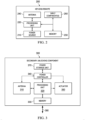
- Figure 2 illustrates an embodiment keyless remote 200.
- the keyless remote includes a power source 210, a processing unit 220, a memory 230, an antenna 240, and optionally one or more input components 250, which may (or may not) be arranged as shown.
- the keyless remote 200 may also include additional components that are not shown.
- the keyless remote 200 may be a key-fob, a cellular phone (e.g., smartphone), a smart card, or any other device capable of providing an external power source and optionally communicating authorization signals with the electronic keyless door latch system 110.
- a combination of these devices may be used as the keyless remote 200.
- a typical smartphone contains about 300 joules (J) of energy at full charge, which can provide enough energy to actuate the primary unlocking component.
- the smartphone may be limited in the amount of power it can transfer.
- using NFC technology at about 10 mW nearly 17 minutes is required to provide 10 J to the electronic keyless door latch system, which is impractical.
- Embodiments of this disclosure utilize a secondary unlocking component capable of operating using significantly less energy, which provides a backup unlocking mechanism that significantly minimizes transfer time and provides for a practical means to unlatch and / or unlock the door.
- a smartphone may be used as a virtual digital key to unlock the vehicle using a common industry standard communication protocol (e.g., digital key standard from the car connectivity consortium) or a propriety communication format (e.g., Tesla or Ford using phone as a key (PAAK) feature).
- a common industry standard communication protocol e.g., digital key standard from the car connectivity consortium
- a propriety communication format e.g., Tesla or Ford using phone as a key (PAAK) feature
- close-range near field communication NFC
- a software application on the smartphone may provide temporary access to the vehicle by an authorized user. This may be advantageous, for example, in car sharing or rental car use cases.
- the power source 210 may be any component that provides an electrical power source to the keyless remote 200.
- Examples of the power source 210 include nickel metal hydride (NiMH), nickel-cadmium (NiCd), nickel-zinc (NiZn), and lithium-ion (Li-ion) cells.
- the processing unit 220 implements various processing operations for the keyless remote 200.
- the processing unit 220 can perform signal coding, data processing, power control, input/output processing, or any other functionality enabling the operation of the keyless remote 200.
- the processing unit 220 includes any suitable processing or computing device configured to perform programming operations.
- the processing unit 220 could, for example, include a microprocessor, a microcontroller, a digital signal processor, a field programmable gate array (FPGA), or an application specific integrated circuit (ASIC).
- the keyless remote 200 is shown to have a single processing unit, however, in some embodiments multiple processing units may be included.
- the processing unit 220 may generate encoded or non-encoded wireless signals in a standard or a proprietary format to be transmitted to the electronic keyless door latch system 110.
- the wireless signal may be an infrared (IR) signal or an ultrasonic signal.
- the wireless signals may be used to communicate an authorization signal to satisfy a condition to operate the electronic keyless door latch system 110 in the secondary operational mode.
- the processing unit 220 may use data stored in the memory 230 to generate and / or encode the wireless signal.
- the processing unit 220 may receive encoded or non-encoded wireless signals in a standard or proprietary format using the antenna 240 from the electronic keyless door latch system 110 as feedback.
- the wireless signals may be encoded or decoded and may be communicated using a standard or a proprietary format.
- the memory 230 may be configured to store data, programs, and other information and to make the data, programs, and other information accessible to the processing unit 220.
- the memory 230 may include any type of non-transitory system memory such as static random access memory (SRAM), dynamic random access memory (DRAM), synchronous DRAM (SDRAM), read-only memory (ROM), or a combination thereof.
- SRAM static random access memory
- DRAM dynamic random access memory
- SDRAM synchronous DRAM
- ROM read-only memory
- the memory 230 may include ROM for use at boot-up, and DRAM for program and data storage for use while executing programs.
- the memory 230 may include, for example, one or more of a solid-state drive, hard disk drive, a magnetic disk drive, removable memory drive, or an optical disk drive.
- the antenna 240 may be used to transmit power from the keyless remote 200 through contactless transfer of energy.
- the antenna 240 may include one or more inductors (e.g., wrapped coil of wire or looped coil) that utilizes mutual coupling to enable the contactless transfer of energy from the keyless remote 200 to the electronic keyless door latch system 110.
- the antenna 240 may be an NFC antenna and capable of operating under NFC protocols / standards at a frequency of around 13.56 Megahertz (MHz).
- the input component can include one or more input triggers, such as an electronic or mechanical button.
- a user of the keyless remote 200 upon pressing or activating a button on the keyless remote can generate a signal to the processing unit 220, which can excite an alternating current at the antenna 240 using the power source 210.
- the triggering of the button can generate the wireless signal that can be received and / or decoded by the electronic keyless door latch system 110 to verify that an authorized user is triggering the unlocking of the door 102 in the secondary operational mode.
- the operational switch between the primary operation mode and the secondary operational mode at the electronic keyless door latch system 110 may be seamless to the user.
- a user wanting entry to the vehicle may bring the keyless remote 200 near the electronic keyless door latch system 110 to unlock the vehicle.
- the keyless remote 200 provides an external power source for the electronic keyless door latch system 110.
- the electronic keyless door latch system 110 uses the power derived from the keyless remote 200, determines that the vehicle's primary power supply is inaccessible to the keyless door latch system, causing the secondary operational mode to become active. This may be advantageous when the vehicle's primary power supply is functioning but inaccessible to the door 102 as a result of, for example, a fault in the power line from the vehicle's primary power supply to the electronic keyless door latch system 110.
- the keyless remote 200 may receive a feedback signal from the electronic keyless door latch system 110 indicating a fault in the primary unlocking component 116 and the need for repair.
- Figure 3 illustrates a schematic of an embodiment secondary unlocking component 118 used to unblock a backup locking mechanism in the electronic keyless door latch system 110.
- the secondary unlocking component 118 includes an antenna 310, a processing unit 320, a memory unit 330, a power controller 340, and an actuator 350, which may (or may not) be arranged as shown.
- the secondary unlocking component 118 may include a power storage unit 370 for temporary power storage.
- the secondary unlocking component 118 may include other components that are not shown.
- the antenna 310 may be any type of receiving device used to receive power from the keyless remote 200, for example to operate in the secondary operational mode, through contactless transfer of energy.
- the antenna 310 may include one or more inductors (e.g., wrapped coil of wire or looped coil) that utilizes mutual coupling to enable the contactless transfer of energy from the keyless remote 200 to the secondary unlocking component 118.
- the antenna 310 may be an NFC antenna and capable of operating under NFC protocols / standards at a frequency of around 13.56 Megahertz (MHz).
- the antenna 310 may be used to receive and / or transmit wireless signals (i.e., data) between the secondary unlocking component 118 and the keyless remote 200.
- the wireless signals may be encoded or decoded and may be communicated using a standard or a proprietary format.
- the antenna 310 may be any device capable of receiving a power signal and / or authentication signal from the keyless remote.
- the signal may be an infrared (IR) signal or an ultrasonic signal.
- the wireless signal is able to provide a power source to the electronic keyless door latch system 110 that is less than 10 milliwatt (mW).
- the processing unit 320 implements various processing operations for the secondary unlocking component 118.
- the processing unit 320 can perform signal coding, data processing, power control, input/output processing, or any other functionality enabling the secondary unlocking component 118 to operate in the electronic keyless door latch system 110.
- the processing unit 320 includes any suitable processing or computing device configured to perform programming operations.
- Each processing unit 320 could, for example, include a microprocessor, a microcontroller, a digital signal processor, a field programmable gate array (FPGA), or an application specific integrated circuit (ASIC).
- the secondary unlocking component 118 is shown to have a single processing unit, however, in some embodiments multiple processing units may be included.
- the processing unit 320 may receive encoded or non-encoded wireless signals from the processing unit 220 of the keyless remote 200 through the antenna 310.
- the wireless signals may be used to communicate an authorization signal to satisfy a condition to operate the electronic keyless door latch system 110 in the secondary operational mode.
- the processing unit 320 may use data stored in the memory 330 to decode the wireless signal and / or to verify the authenticity of the wireless signal.
- the processing unit 320 may transmit encoded or non-encoded wireless signals through the antenna 310 to the keyless remote 200 as a feedback signal.
- the processing unit 320 can communicate with the vehicle's main computer or with other components in the vehicle, such as the primary unlocking component 116 using the communication bus 360. In some embodiments, the processing unit 320 can use the communication bus 360 to determine whether the primary unlocking component 116 is inaccessible or whether the primary unlocking component 116 is not receiving power from the vehicle's power supply. In another embodiment, the processing unit 320 can use the communication bus 360 to communicate a feedback with the vehicle's main computer and indicating a fault with the primary unlocking component 116.
- the memory 330 may be configured to store data, programs, and other information and to make the data, programs, and other information accessible to the processing unit 320.
- the memory 330 may include any type of non-transitory system memory such as static random access memory (SRAM), dynamic random access memory (DRAM), synchronous DRAM (SDRAM), read-only memory (ROM), or a combination thereof.
- SRAM static random access memory
- DRAM dynamic random access memory
- SDRAM synchronous DRAM
- ROM read-only memory
- the memory 330 may include ROM for use at boot-up, and DRAM for program and data storage for use while executing programs.
- the memory 330 may include, for example, one or more of a solid-state drive, hard disk drive, a magnetic disk drive, removable memory drive, or an optical disk drive.
- the power controller 340 may be used to condition the received power at the antenna 310 to provide a conditioned power source to the various components of the secondary unlocking component 118.
- the power controller 340 and the processing unit 320 may be the same component or manufactured on a same controller chip to allow for a more elegant, efficient, and smaller form factor design of the secondary unlocking component 118.
- the secondary unlocking component 118 may also include a power storage unit 370 that can be used by the power controller 340 for temporary power storage.
- the power storage unit 370 may be a battery or a capacitor.
- the power controller 340 may itself include a capacitor for temporary power storage.
- the actuator 350 may be any component that receives a control signal from the processing unit 320 and a power source from the power controller 340 and, in response to receiving the control signal, converts the energy from the power source to activate a pin, switch, valve, or to cause a linear or circulator motion to move or displace a mechanical component coupled to the actuator 350.
- the actuator 350 can be a solenoid, a micro-solenoid, an electrical motor, a stepper motor, or similar components operational using low amounts of energy ( e.g., less than 10 W).
- the keyless remote 200 excites an alternating current through the antenna 240, for example, in response to a user selecting a key or button on the keyless remote 200.
- the induced electrical current is then conditioned using the power controller 340.
- the processing unit 320 uses the energy received from the power controller 340 to power up and to determine whether or not the necessary conditions to operate the electronic keyless door latch system in the secondary operational mode have been met. If the processing unit 320 determines that the necessary conditions have been met, the processing unit 320 transmits a control signal to the actuator 350.
- the Actuator 350 upon receiving the control signal, converts the energy from the power controller 340 to a mechanical movement in the secondary operational mode as discussed.
- the processing unit 320 may generate a feedback signal that is communicated to the vehicle, directly or indirectly through the keyless remote 200.
- the feedback signal can be used to indicate a failure of the vehicle's primary power source in providing a power source to the primary unlocking component 116 and the need for repair.
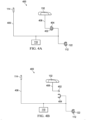
- Figures 4A-B illustrate a simplified locking mechanism of a vehicle door 102.
- Figure 4A illustrates the locking mechanism 400 when the locking component 114 is in the unlocked position.
- Figure 4B illustrates the locking mechanism 400 when the locking component 114 is in the locked position.
- the locking component 114 is connected to the door striker 112 and to the lever striker 404 through a mechanical rod 406.
- the lever 132 is connected to the lever striker plate 402 through a second mechanical rod 408.
- the locking component 114 is in the unlocked position.
- the lever striker 404 is latched and in contact with the lever striker plate 402.
- the movement of the second mechanical rod 408, through the positioning of the lever 132 unlatches the door striker 112 from the door striker plate 122 through the mechanical rod 406 and allows the opening of the vehicle door.
- the locking component 114 can be moved from the unlocked position ( i.e., Figure 4A ) to the locked position ( i.e., Figure 4B ) by the electronic keyless door latch system 110.
- the vehicle's power supply provides the electrical energy to mechanically move the locking component 114 from the unlocked position to the locked position, and vice versa.
- locking mechanism shown in Figures 4A-B is simplified version of a commercial locking mechanism and is illustrated as such for purposes of the discussion.
- a commercial locking mechanism may have additional components and complexities to, for example, address safety issues and to provide a smoother operation.
- embodiments of this disclosure can be readily adapted to these commercial locking mechanisms.
- Figure 5 illustrates an embodiment door latch 500 that uses a cone clutch mechanism to unlatch (i.e., engage / disengage) the driven shaft 510 from the driving shaft 520.
- a dashed line 550 is shown to separate components accessible on an exterior 570 of the vehicle from components accessible on an interior 560 of the vehicle.
- the cone clutch is a type of friction (i.e., operates under the principle of friction) cone clutch that may be used to engage and disengage one shaft (e.g., driven shaft 510) to and from another shaft (e.g., driving shaft 520). It is noted that embodiment methods and structures in the present disclosure may similarly be implemented in any general clutch system / mechanism and more generally to any system / mechanism that when actuated, permits an energy source, from an exterior of the door, to be transferred to a keyless latch system to unlatch the door or to cause a stored energy in the keyless door latch system to unlatch the door.
- the driven shaft 510 is part of the unlatching mechanism attached to the interior door handle 512.
- a force from the interior door handle 512 is transferred to a force at the unlocking component 114 and / or the door striker 112 through the gear 514.
- the transferred force at the door striker 112 causes the door striker 112 to unlatch from the door striker plate 122.
- the force at the interior door handle 512 may unlatch the door striker 112 regardless of the locking component 114 being in a locked or an unlocked position. However, in some embodiments, a first force from the interior door handle may first cause the locking component 114 to move from the locked position to the unlocked position. A second force from the interior door handle may then be transferred to the door striker 112 to unlatch the door striker 112 from the door striker plate 122 as described above, with respect to Figures 4A-B .
- the driving shaft 520 is part of the unlatching mechanism attached to the exterior door handle 522.
- the driving shaft 520 is connected to an outer (i.e., female) cone 524 and the driven shaft 510 is connected to an inner ( i.e., male) cone 515.
- a friction lining 526 provides frictional contact between the inner section of the outer cone 524 and an outer section of the inner cone 515.
- the friction lining may be on the inner cone 515.
- the friction lining 526 may be on the outer cone 524.
- both inner cone 515 and outer cone 524 may each have a friction lining 526.
- the engagement spring 540 drives the driven shaft 510 towards the driving shaft 520.
- the friction lining 526 generates a frictional contact between the inner cone 515 and the outer cone 524.
- the friction lining 526 mechanically connects the inner cone 515 to the outer cone 524, and as a result, connects the driving shaft 520 to the driven shaft 512.
- the clutch actuator 530 may be used to decompress or compress the engagement spring 540 and to engage or disengage the inner cone 515 from the outer cone 526.
- a force at the exterior door handle 522 provides the same torque needed to unlatch the door striker 112 from the door striker plate 122 as if the force originated from the interior door handle 512.
- the inner cone 515 and the outer cone 524 are disconnected, and as a result, the driving shaft 520 is disconnected from the driven shaft 512.
- an actuation (e.g., pressing) of the clutch actuator 530 may be used to separate the inner cone 515 from the outer cone 524.
- the engagement spring 540 is in the compressed position and does not provide a force to maintain a frictional contact, at the friction lining 526, between the inner cone 515 and the outer cone 524.
- a force at the exterior door handle 522 does not unlatch the door striker 112 from the door striker plate 122.
- Figures 6A-C illustrate embodiment cone clutch type door latches that engage the driven shaft 510 to the driving shaft 520 using the actuator 350 in the secondary unlocking component 118.
- the actuator 350 actuates a pin or lever to directly or indirectly engage the two shafts.
- a motion or force shown as element numbers 522 and 684 provided at the exterior 570 of the vehicle results in the same effect as if the motion or force (shown as element number 512) was attempted from the interior 560 of the vehicle. Therefore, by providing a minimal amount of energy (i.e., less than 10 millijoules) to the actuator 350, the vehicle door can be unlocked and / or unlatched.
- the mechanical force 522 exerted on the exterior handle door 132 similar to the force exerted to unlock a vehicle door from the interior of the vehicle, provides the auxiliary or backup force in the secondary operational mode.
- Figure 6A illustrates an embodiment cone clutch type door latch 600 that uses a clutch bypass mechanism to engage the inner cone 515 to the outer cone 524, in the secondary operational mode.
- the cone clutch of Figure 6A is similar in operation to the cone clutch of Figure 5 .
- a pin 610, a spike 620, and a guidance slot 630 in the cone clutch of Figure 6A may be used as a bypass to the clutch actuator 530 to engage the inner cone 515 to the outer cone 524.
- the actuator 350 can actuate the pin 610 and drive the spike 620, in the guidance slot 630, to move the inner cone 515 towards the outer cone 524.
- a force at the exterior door handle 522 can provide the torque needed to unlatch the door striker 112 from the door striker plate 122.
- the spike 620 falls back to its original position. Additional details, with respect to the movement of the spike 620 in the guidance slot 630, are provided in Figure 7 .
- the guidance slot 630 in the inner cone 515 may have a slot geometry that allows normal movement of the inner cone 515 even if the spike 620 is inserted in the guidance slot 630 during normal operation. This slot geometry advantageously prevents damage of the door latch mechanism in case the lock is actuated while the spike 620 is inserted in the guidance slot 630.
- Figure 6B illustrates an embodiment cone clutch type door latch 650 that uses an actuation shaft 670 to move the inner cone 515 towards the outer cone 524, in the secondary operational mode.
- the cone clutch of Figure 6B is similar in operation to the cone clutch of Figure 5 .
- the actuation shaft 670 having a spring-loaded mechanism, may be used to move the inner cone 515 towards the outer cone 524.
- the actuator 350 can actuate the pin 660 to release a compressed spring in the actuation shaft 670.
- the release of the compressed spring in the actuation shaft 670 drives the clutch actuator 530 and pushes the inner cone 515 towards the outer cone 524 to create a frictional contact at the frictional lining 526.
- a force at the exterior door handle 522 can provide the torque needed to unlatch the door striker 112 from the door striker plate 122.
- the spring in the actuation shaft 670 spring can be compressed by a reverse movement of the pin 660 and to return to its original position.
- Figure 6C illustrates an embodiment cone clutch type door latch 680 that uses an actuation shaft 682 to move the inner cone 515 towards the outer cone 524, in the secondary operational mode.
- the cone clutch of Figure 6C is similar in operation to the cone clutch of Figure 6B .
- the actuation shaft 682 in Figure 6C is accessible from the exterior 570 of the vehicle and may not be spring-loaded.
- the actuator 350 can actuate the pin 660 to unblock the movement of the actuation shaft 682.
- the actuation shaft 682 is not spring loaded. Therefore, the actuation of the pin 660 does not automatically move the actuation shaft 682.
- an exterior force 684 exerted on the actuation shaft 682 from the exterior 570 of the vehicle, drives the clutch actuator 530, pushing the inner cone 515 towards the outer cone 524, and creating the frictional contact at the frictional lining 526.
- a force at the exterior door handle 522 can provide the torque needed to unlatch the door striker 112 from the door striker plate 122.
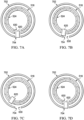
- Figures 7A-D illustrate an embodiment clutch bypass mechanism used to engage an inner cone 516 to an outer cone 6524 of a cone clutch. As shown in Figure 7A , the pin 610 is not actuated and the spike 620 does not connect the outer cone 524 to the inner cone 516.
- the spike 620 is driven into the guidance slot 630 of the inner cone 516 by the cam lip 702.
- the inner cone 516 is moving towards the outer cone 524 to engage the driven shaft 510 to the driving shaft 520.
- the spike 620 also returns to its original position.
- the pin 610 also returns to its original position.
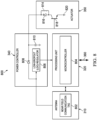
- FIG 8 illustrates a schematic 800 of an embodiment secondary unlocking component.
- the antenna 310 includes an NFC tag antenna 802 capable of exchanging an I2C serial protocol format signal with the antenna 240 of the keyless remote 200.
- the I2C signal can carry the authorization and / or authentication signals used to determine whether the keyless remote 200 is authorized to unlock the vehicle.
- the NFC tag antenna 802 can be used in the induced power transference, compliant with the NFC protocols, from the antenna 240.
- the processing unit 320 includes a microcontroller 804 with an internal memory unit.
- the microcontroller 804 can receive the I2C signal from the NFC tag antenna 802 and transmit an I2C signal using the NFC tag antenna 802 to communicate with the keyless remote 200.
- the authorization signal can be verified by the microcontroller 804 using data stored in its internal memory.
- the microcontroller 804, after verifying that the keyless remote 200 is authorized to unlock the door, can determine whether the primary unlocking component 116 is disabled using the communication bus 360 and, based thereon, generate a control signal to the actuator 350.
- the power controller 340 includes a low-dropout (LDO) regulator 806, a diode 808, and a shunt capacitor 810.
- LDO low-dropout
- the shunt capacitor 810 can act as a storage unit to charge and provide the necessary power to the actuator 350.
- the diode 808 can be used to prevent current from traveling in the reverse direction, for example, during charging of the shunt capacitor 810.
- the attenuator 350 includes a transistor 818, such as a field effect transistor (FET), having a gate node, a drain node, and a source node.
- the gate node of the transistor 818 receives the control signal from the microcontroller 804 in the secondary operational mode.
- the drain node of the transistor 818 is connected to a reference voltage.
- the source node is connected to the diode 816, which is arranged in parallel with the wounded coil (i.e., solenoid) 814.
- the wounded coil 814 can be a micro-solenoid capable of operating at low power to actuate a pin, valve, or lever.
- the diode 816 can be a flywheel diode used to protect the wounded coil 814.
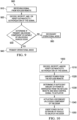
- Figure 9 is a flowchart of an embodiment method 900 for unlocking a vehicle door equipped with an electronic keyless door latch system 110, having a primary and a secondary operational mode, using a keyless remote 200.
- the electronic keyless door latch system 110 receives a signal from the keyless remote 200.
- the signal may be received at the antenna 310.
- the signal may be encoded and / or encrypted.
- the processing unit 320 decodes and / or decrypts the wireless signal received at step 910 to verify the authenticity of the signal and the authorization to unlock the vehicle door.
- the processing unit 320 determines if the primary unlocking component is capable of unlocking the door. In an embodiment, the processing unit 320 can determine whether the energy provided by the vehicle's primary power supply meets a minimum threshold requirement. In another embodiment, the processing unit 320 may detect a fault at the primary unlocking component as a result of a bad or dying car battery, a mechanical failure in the primary unlocking mechanism (e.g., fried primary solenoid), power line fault from the car battery to the primary unlocking component, signal fault at the vehicle computer or primary unlocking component, a failure to receive a confirmation signal regarding proper functioning of the vehicle computer or primary unlocking component, or other reasons to determine that the primary unlocking component is capable of unlocking the door.
- a mechanical failure in the primary unlocking mechanism e.g., fried primary solenoid
- the processing unit 320 can determine whether or not the primary unlocking component is capable of unlocking the door by determining the occurrence or an indication of the occurrence of an event or a combination of events. For instance, the processing unit 320 can determine that a child is sitting on the backseat of the vehicle, that the keyless remote is in the vehicle, and that the vehicle doors are locked. The combination of these events may be selected, or programmed, to trigger a flag or to indicate that the primary unlocking component is not capable of unlocking the door.
- steps 920 and 930 are reversed. In some embodiments, steps 920 and 930 are performed at the same time. If the processing unit 320 determines that the primary unlocking component is capable of unlocking the door, that the signal received at step 910 is verified to be authentic, and / or the signal received at step 910 provides authorization to unlock the door, at step 940, the primary unlocking component 116 operating in the primary operational mode, unlocks the locking component 114 using the energy provided by the vehicle's primary power supply.
- the processing unit 320 determines that primary unlocking component is not capable of unlocking the door, but that the signal received at step 910 is verified to be authentic and / or the signal received at step 910 provides authorization to unlock the door, at step 950, the secondary unlocking component 118 operating in the secondary operational mode actuates the actuator 350 using the energy provided from the keyless remote 200.
- FIG 10 is a flowchart of an embodiment method 1000 for unlocking a vehicle door in the secondary operational mode.
- the electronic keyless door latch system 110 is operating in the secondary operational mode in response to the processing unit 320 determining that the vehicle's primary power supply is unable to provide a minimum energy to the primary unlocking component 116.
- step 1010 the processing unit 320 verifies the authenticity of the signal and the authorization to unlock the door from the signal received at step 910.
- step 1010 may be a duplicate to step 920 of Figure 9 , or replace step 920 above. If the signal received at step 910 is determined to not be an authentic signal and / or that the signal does not provide authorization to unlock the vehicle door, the door remains locked.
- step 1020 if the processing unit 320 determines that the minimum power threshold of the vehicle's primary power supply is not met, but that the signal received at step 910 is verified to be authentic and / or the signal received at step 910 provides authorization to unlock the door, the power controller 340 begins to harvest power from the keyless remote 200 for the operation of the secondary unlocking component 118.
- the processing unit 320 determines that the power controller 340 is capable of providing sufficient energy to the actuator 350 and transmits a control signal to the actuator 350.
- the actuator 350 may actuate a secondary unlocking component of the door.
- the actuating of the secondary unlocking component permits an energy source, from an exterior of the door, to be transferred to the keyless door latch system to unlatch the door.
- the actuating of the secondary unlocking component causes a stored energy in the keyless door latch system to unlatch the door.
- a user's motion on a knob, lever, or similar structure at the exterior of the vehicle generates the force that is transferred to unlatch the door from the vehicle frame and/ or to unlock the vehicle door.
- a user's motion on a knob, lever, or similar structure at the exterior of the vehicle generates the force that is transferred to unlatch the door from the vehicle frame and/ or to unlock the vehicle door.
Landscapes
- Physics & Mathematics (AREA)
- Engineering & Computer Science (AREA)
- General Engineering & Computer Science (AREA)
- General Physics & Mathematics (AREA)
- Mechanical Engineering (AREA)
- Electromagnetism (AREA)
- Lock And Its Accessories (AREA)
Description
- The present disclosure relates generally to locks and latches, and, in particular embodiments, to a keyless entry system having a backup unlatching component powered by an external power source.
- Automobile manufacturers include keyless entry systems to provide controlled remote access to the interior of a vehicle. A keyless entry system performs the functions of a traditional mechanical lock without the mechanical lock (i.e., key lock) hardware. The keyless entry system typically includes a keyless remote that operates in tandem with a keyless door latch system fitted in, for example, a vehicle door. The keyless remote communicates with the keyless door latch system for access control. An electrical power source of the vehicle (e.g., vehicle battery) provides the energy to operate the keyless door latch system.
- Documents
US 2015/102904 A1 ,US 2016/060909 A1 andUS 6 062 613 A may be of interest for the present application. - Technical advantages are generally achieved by embodiments of this disclosure, which describe a keyless entry system having a backup unlatching component powered by an external power source.
- Generally, the present application relates to a door assembly for a vehicle according to claim 1. The door assembly comprises a door, hinges, a doorframe, an electronic keyless door latch system and a locking component. The electronic keyless door latch system includes a door striker assembly, wherein the door striker assembly includes a door striker plate mounted on the surface of the doorframe, wherein the electronic keyless door latch system includes a door striker, and a primary and secondary unlocking component. The locking component is configured to be in a locked position or in an unlocked position, wherein the locking component is connected to the electronic keyless door latch system.
- The interior door handle is configured such that motion on the interior door handle by a user results in the unlocking of the locking component and unlatching of the door strike plate from the door striker. The primary unlocking component is controllable via a keyless remote and used to lock or unlock the locking component from the outside of the vehicle, wherein, in a primary operational mode, a primary power supply provides the power to unlock the locking component by using the primary unlocking component.
- According to the present invention, the electronic keyless door latch system further comprises an exterior door handle including a lever that is contact with the electronic keyless door latch system when the locking component is in the unlocked position, whereby the lever can unlatch the door striker from the door striker plate when the locking component is in the unlocked position, and the exterior door handle is in contact with the electronic keyless door latch system through the mechanical connection that is disconnected when the locking component is in the locked position. The secondary unlocking component is controlled via the keyless remote, wherein the secondary unlocking component is enabled when the primary unlocking component is unable to unlock the locking component.
- Specifically, the secondary unlocking component comprises an antenna adapted to receive a wireless signal from the keyless remote, a memory unit, a processing unit, power controller and an actuator.
- The processing unit configured to decode and/or decrypt the wireless signal received to verify the authenticity of the signal and the authorization to unlock the door and determine whether the primary unlocking component is capable of unlocking the locking component by determining whether the energy provided by the primary power supply meets a minimum threshold requirement. In response to determining that the primary unlocking component is not capable of unlocking the locking component but the signal received is verified to be authentic and provide authorization to unlock the door, the secondary unlocking component operating in a secondary operating mode actuates the actuator using the energy provided from the keyless remote.
- The power controller is configured to begin to harvest power from the wireless signal for the operation of the secondary unlocking component, wherein the processing unit is further configured to determine that the power controller is capable of providing sufficient energy to the actuator and transmits a control signal to the actuator.
- The actuator is configured to receive the control signal from the processing unit and the power from the power controller, and, in response to receiving the control signal, convert the energy from the power controller to actuate a pin or lever to engage a shaft, connected to the interior door handle, to a shaft, connected to the exterior door handle, whereby, due to the mechanical connection between the two shafts, motion on the exterior door handle by a user results in the unlocking of the locking component and unlatching of the door striker assembly from the door striker.
- In various embodiments, the antenna is a near-field communication (NFC) antenna capable of operating within NFC communication protocols
In various embodiments, the keyless door latch system further includes a non-transitory memory storage configured to store an authorization verification key. The received signal further includes an authorization signal. The processing unit includes a microcontroller configured to verify an authenticity of the authorization signal in accordance with the authorization verification key, and based thereon, generate the control signal. - In various embodiments, the secondary unlocking component includes a clutch component.
- For example, in various embodiments, the clutch component comprises an inner cone connected to the shaft connected to the interior door handle, wherein the inner cone has a first guidance slot. An outer cone is connected to the shaft connected to the exterior door handle, wherein the outer cone has a second guidance slot, wherein the first and second guidance slot are aligned with each other. A spike located within the first and second guidance slot, the spike being configured to move the inner cone towards the outer cone based on an actuation of the pin in the secondary unlocking component and to mechanically connect the inner cone and the outer cone.
- Alternatively, in various embodiments, the clutch component comprises an inner cone connected to the shaft connected to the interior door handle. A clutch actuator is connected to the inner cone. An outer cone is connected to the shaft connected to the exterior door handle. An actuation shaft is configured to engage the clutch actuator causing the inner cone to move towards the outer cone and mechanically connect the inner cone to the outer cone, wherein in the secondary operational mode, the actuator actuates the pin to release a compressed spring in the actuation shaft, whereby the actuation shaft drives the clutch actuator and pushes the inner cone towards the outer cone to create a frictional contact at a frictional lining.
- In various embodiments, the actuator is a solenoid, a micro-solenoid, an electrical motor, or a stepper motor.
- Embodiments can be implemented in hardware, software, or in any combination thereof.
- For a more complete understanding of the present disclosure, and the advantages thereof, reference is now made to the following descriptions taken in conjunction with the accompanying drawings, in which:
-
Figure 1 illustrates an embodiment vehicle door assembly with an electronic keyless door latch system; -
Figure 2 illustrates a block diagram of an embodiment keyless remote; -
Figure 3 illustrates a block diagram of an embodiment secondary unlocking component in the electronic keyless door latch system; -
Figures 4A-B illustrate a simplified locking mechanism in a vehicle door; -
Figure 5 illustrates an embodiment cone clutch type used in a door latch mechanism; -
Figure 6A illustrates an embodiment cone clutch having a clutch bypass mechanism; -
Figure 6B illustrates an embodiment cone clutch having a spring loaded actuation shaft; -
Figure 6C illustrates an embodiment cone clutch having an externally accessible actuation shaft; -
Figures 7A-D illustrate an embodiment clutch bypass operation in the clutch bypass mechanism; -
Figure 8 illustrates a schematic of an embodiment secondary unlocking component; -
Figure 9 is a flowchart of an embodiment method for unlocking a vehicle door equipped with a keyless entry system; and -
Figure 10 is a flowchart of an embodiment method for unlocking a vehicle door in a secondary operational mode of a keyless entry system. - This disclosure provides many applicable inventive concepts that can be embodied in a wide variety of specific contexts. The specific embodiments are merely illustrative of specific configurations and do not limit the scope of the claimed embodiments. Features from different embodiments may be combined to form further embodiments unless noted otherwise. Variations or modifications described with respect to one of the embodiments may also be applicable to other embodiments.
- While the inventive aspects are described primarily in the context of an unlocking mechanism used in a door of an automobile and using near-field communication (NFC) protocol/standards, it should also be appreciated that these inventive aspects may also be applicable to any general unlocking mechanism using other standard or proprietary methods of communication and power transference. For example, the embodiment methods and systems described in this disclosure can be similarly applied to a keyless entry system in an entry gate, entry door, shared storage area, storage locker, delivery box, desk drawer, hotel room entry points, rental unit entry points, windows, and similarly controlled units and areas.
- Furthermore, although embodiments of this disclosure are described using a clutch mechanism, and particularly a cone clutch structure mechanically moving an inner cone relative to an outer cone, it should be appreciated that these inventive aspects are also applicable to any general clutch system / mechanism and more generally to any system / mechanism that when actuated, permits an energy source, from an exterior of the door, to be transferred to a keyless latch system to unlatch the door or to cause a stored energy in the keyless door latch system to unlatch the door.
- As described above, a keyless door latch system requires an electrical power source for operation. Car manufacturers may include a mechanical lock as a backup solution to add additional means of access to the vehicle. Another backup solution is the addition of an auxiliary power source in the vehicle to be used as a backup to the primary power source.
- In reality, situations may arise when these backup solutions become deficient. As a way of example, in a ride-sharing use case, the mechanical key may be easily copied by a customer, which presents a risk of theft or unauthorized use. Additionally, the mechanical key is required to be physically transferred from one authorized user to another, which can present additional complications. As another example, the auxiliary power source, similar to the primary power source, can easily discharge of energy if remained idle for a period of time. Accordingly, systems and techniques to unlock a keyless entry system when the primary unlocking mechanism becomes unavailable are desired.
- Embodiments of this disclosure provide systems and techniques to unlock a keyless entry system using a secondary unlocking component. In particular, in an embodiment, a keyless door latch system in the keyless entry system is capable of operating in two modes of operation. In a primary operational mode (i.e., default mode of operation), a primary source of power provides energy to a primary unlocking component used to unlock a locking mechanism. In a secondary operational mode (i.e., when the primary operational mode becomes unavailable), an external power source (i.e., keyless remote) provides energy to a secondary unlocking component to unlock the locking mechanism.
- In an embodiment, the secondary operational mode is activated after determining that the primary unlocking component is unavailable. For example, when the power supply is unavailable to the primary unlocking component, when the primary power source is unable to provide a minimum amount of power to the primary unlocking component (i.e., less than a minimum power threshold), or a as a result of a failure to one of the primary power supply, the primary unlocking component, a communication link between the two components, a mechanical link between the components, or the like.
- In another embodiment, the secondary operational mode is activated as a feature in the keyless entry system in response to an occurrence of an event or a combination of events. For instance, the keyless entry system, or a computer in the vehicle, may detect that the vehicle is locked, that the keyless remote is inside the vehicle, and that someone is located in the backseat of the vehicle. As a safety feature, a user can enable a feature that upon detecting a combination of these items, to enable the secondary operational mode.
- As another example, the secondary unlocking component may be activated as a result of an accident involving the vehicle, a failure of the vehicle engine, a fire near or within the vehicle, disablement of the driver or passenger, or the like. A user can enable events or combination of events, that when detected, enables the secondary operational mode. This can advantageously give emergency personal quick access the interior vehicle.
- In another example, a beacon inside the vehicle may detect a physical location of the keyless remote inside the vehicle. For instance, the keyless entry system may detect that the vehicle has been locked and that the keyless remote is located in the trunk of the vehicle. In response, the secondary operational mode may be enabled.
- The feature may be pre-programmed in the vehicle, programmed during a service visit, through an over-the-air (OTA) update, through an interface with a smartphone application, or the like. The feature may be user selectable via an application interface using, for example, an interface on the vehicle, smartphone application, or the like.
- In any of these embodiments, the keyless door latch system includes a low energy backup mechanical device that is operational without the need for any onboard power source available on the vehicle. The secondary unlocking component provides a low energy backup solution to unlock the vehicle door. In some embodiments, the secondary unlocking component may actuate a mechanism typically used to unlock the vehicle door from the interior of the vehicle. In other embodiments, the secondary unlocking component provides a means to unlock or unlatch the door using an external force from the outside of the vehicle. The secondary unlocking component does not prevent the unlocking of the door in the primary operational mode, however, it is prevented from unlocking the door in the primary operational mode. The secondary unlocking component provides an auxiliary method of unlocking the vehicle door using minimal power in the event of, for example, a failure to the primary operational mode or as a selected feature.
- Aspects of this disclosure provide embodiment methods and solutions that advantageously use the mechanical power of the hand to unlock the vehicle door from the exterior of the vehicle. Thus providing a low power solution to unlock the vehicle door in the event of a fault at the primary unlocking component. The fault at the primary unlocking component may be a result of a bad or dying car battery, a mechanical failure in the primary unlocking mechanism (e.g., fried primary solenoid), power line fault from the car battery to the primary unlocking component, signal fault at the vehicle computer or primary unlocking component, failure to receive a confirmation signal regarding proper functioning of the vehicle computer or primary unlocking component, and other reasons. In other embodiments, the low power solution may be advantageous as a selectable feature that is enabled in response to an occurrence of an event or a combination of events.
- In most vehicles, the pulling on an interior door handle unlocks the vehicle without the need to first unlock a locking component. In some vehicles, a first pull on the interior door handle unlocks the locking component of the door and a second pull on the interior door handle results in the unlatching of the door from the frame of the vehicle. In either case, the motion on the interior door handle results in the unlocking and / or unlatching of the vehicle door from the door frame. Embodiments of this disclosure use the power from the keyless remote to actuate, for example, a pin or lever (i.e., using an actuator in the secondary unlocking component) to engage a shaft, connected to the interior door handle, to a shaft, connected to the exterior door handle. As a result, when the two shafts are engaged, the motion on the exterior door handle results in the same effect as if the motion was attempted from the interior of the vehicle.
- In one embodiment, the shaft, connected to the interior door handle, engages the shaft, connected to the exterior door handle, using a pin and guidance slot in a cone clutch mechanism. The two shafts, when moved towards each other, use frictional contact between an inner cone and outer cone connected to each shaft to mechanically connect to each other. In this embodiment, the pin is driven into the guidance slot using an actuator in the secondary unlocking component.
- In another embodiment, the shaft, connected to the interior door handle, engages the shaft, connected to the exterior door handle, using a spring-loaded actuation shaft. The movement of a pin or lever, using an actuator in the secondary unlocking component, drives a clutch actuator in the cone clutch mechanism to move the inner and outer cone towards each other, which results in the mechanical connection between two shafts.
- In yet another embodiment, the shaft, connected to the interior door handle, engages the shaft, connected to the exterior door handle, using an actuation shaft using a force from the exterior of the vehicle. The movement of a pin or lever, using an actuator in the secondary unlocking component, allows the force to move the actuation shaft and drive a clutch actuator in the cone clutch mechanism to move the inner and outer cone towards each other, which results in the mechanical connection between two shafts.
- In any of these cases, the inner cone and outer cone when engaged, mechanically connects the shaft, connected to the interior door handle, to the shaft, connected to the exterior door handle. These solutions make a mechanical lock redundant and unnecessary, which results in a reduction in the complexity of the unlocking mechanism in a door assembly.
- In some embodiments, the operational switch between the primary operational mode and the secondary operational mode may be seamless to the user. As an example, a user wanting entry to the vehicle may bring a keyless remote near the keyless door latch system. The keyless remote provides the external power source for the operation of a controller in the keyless door latch system through, for example, an inductive transference of power. The controller, using the power derived from the keyless remote, determines that the primary power supply is inaccessible at the primary unlocking component, which results in the secondary operational mode to become the active mode of operation. This may be advantageous when the primary power supply is functioning but inaccessible at the primary unlocking component as a result of, for example, a fault in the power line from the primary power supply. The controller may directly or indirectly, for example through the keyless remote, communicate the fault in the power line to the vehicle computer / user and notify the user of the fault and a need for repair.
- In other embodiments, the keyless remote may have a primary input that is used to unlock the keyless door latch system in the primary operational mode and a secondary input that is used to unlock the keyless door latch system in the secondary operational mode. In this embodiment, the user of the keyless remote may opt to use the secondary input after determining that the primary input is unable to unlock the vehicle. This may be advantageous in reducing power usage by the keyless remote and to improve system efficiency.
- In some embodiments, the keyless remote may be a key-fob, a cellular phone, a smart card, or any other device capable of providing an external power source and optionally communicating authorization and / or authentication signals with the keyless door latch system. In other embodiments, the keyless remote may be a combination of these devices.
- In some embodiments, a pair of a near-field communication (NFC) antennas, using NFC protocols, may be used to transfer power from the keyless remote to the keyless door latch system in the secondary operational mode. NFC provides a widely available and efficient method to provide a power source for the secondary unlocking component. These and other aspects are discussed in greater detail below.
-
Figure 1 illustrates anembodiment door assembly 100 with an electronic keylessdoor latch system 110. Thedoor assembly 100 also includes alocking component 114, adoor striker assembly 120, adoor handle assembly 130, and hinges 140. In addition, the door assembly includes an interior door handle assembly (not shown) accessible to the interior of the vehicle. - The
locking component 114 can be configured to be in a locked position or in an unlocked position (as indicated using the A arrow) to control access to the interior of the vehicle. In some embodiments, thelocking component 114 is a lock button. - The electronic keyless
door latch system 110 includes adoor striker 112, a primary unlockingcomponent 116, and a secondary unlockingcomponent 118. Thelocking component 114 is connected to the electronic keylessdoor latch system 110. The primary unlockingcomponent 116 is the default component used to lock or unlock thelocking component 114 from the outside of the vehicle. The secondary unlockingcomponent 118 is a backup to the primary unlockingcomponent 116. The secondary unlockingcomponent 118 is enabled when the primary unlockingcomponent 116 is unable to unlock thelocking component 114. Exterior to the car, the primary unlockingcomponent 116 and the secondary unlockingcomponent 118 are controlled using akeyless remote 200. - In one embodiment, the primary unlocking
component 116 and the secondary unlockingcomponent 118 are the only unlocking mechanisms in thedoor assembly 100. In such an embodiment, thedoor assembly 100 may not include a mechanical lock capable of locking or unlocking thedoor 102 using a mechanical key. In other embodiments, thedoor assembly 100 may have the necessary components (e.g., lock cylinder) to allow a mechanical key to unlock the vehicle- this is not shown inFigure 1 . - The
door striker assembly 120 includes adoor striker plate 122 mounted on the surface of thedoorframe 104. Thedoor strike plate 122 guides and catches on thedoor striker 112 to create a tight fit when thedoor 102 is in the closed position. The hinges 140 allow thedoor 102 to swing outward from the body of the vehicle. - In some embodiments, unlatching the
door 102 from thedoorframe 104 refers to the unlocking of thelocking component 114. In other embodiments, unlatching thedoor 102 from thedoor frame 104 refers to the unlatching of thedoor strike plate 122 from thedoor striker 112. In other embodiments, unlatching thedoor 102 from thedoorframe 104 refers to the unlocking of the unlockingcomponent 114 and the unlatching of thedoor strike plate 122 from thedoor striker 112. The electronic keylessdoor latch system 110 may include, alternatively or in addition to thelocking component 114, a direct locking component tied to the latching mechanism of thedoor strike plate 122 and thedoor striker 112. In such an embodiment, the latch and lock mechanism may be combined into one structure and / or mechanism. In other embodiments, the latch and lock mechanism and / or structure may be two separate mechanisms and / or structures. As an example, a door may be in a latched position and have a separate lock bolt (e.g., dead bolt lock). - The
door handle assembly 130 includes alever 132 that is in contact with the electronic keylessdoor latch system 110 when thelocking component 114 is in the unlocked position. Thedoor handle assembly 130 is in contact with the electronic keylessdoor latch system 110 through a mechanical connection (e.g., cable) that is disconnected when thelocking component 114 is in the locked position. - In some embodiments, the
door handle assembly 130 may include a knob (not shown). In other embodiments, thedoor handle assembly 130 may be devoid of any particular externally accessible mechanism such as thelever 132. In such embodiments, thedoor handle assembly 130 may release the latching mechanism in thedoor assembly 100 using, for example, an electronic signal, a push mechanism on a surface at a sufficient distance from thehinges 140, or other similar mechanisms. In some embodiments, thedoor assembly 100 may include an electrically or mechanically automated opening mechanism that swings thedoor 102 outward from the body of the vehicle in response to the releasing of the latching mechanism on thedoor assembly 100. - If the
locking component 114 is in the unlocked position, thelever 132 can unlatch thedoor striker 112 from thedoor striker plate 122. When thedoor striker 112 is unlatched from thedoor striker plate 122, the door can be opened. Alternatively, if thelocking component 114 is in the locked position, thelever 132 does not unlatch thedoor striker 112 from thedoor striker plate 122. As thedoor striker 112 remains latched to thedoor striker plate 122, the door remains closed and locked. Further details are provided usingFigures 4A-B . - In a primary operational mode, the vehicle's primary power supply (e.g., vehicle battery) provides the necessary power to unlock the
locking component 114 using the primary unlockingcomponent 116. - In a secondary operational mode, the
keyless remote 200 provides the requisite power for the secondary unlockingcomponent 118 to actuate a pin or lever to engage a shaft, connected to the interior door handle, to a shaft connected to the exterior door handle. The mechanical connection between the two shafts allows a user to motion the exterior door handle and to unlatch thedoor striker 112 from the door striker assembly in a similar principle of operation to the unlocking mechanism used to unlock a door using the interior door handle. Additional details are provided inFigures 6A-B . - The secondary operational mode is activated after determining that the primary unlocking
component 116 is incapable of unlocking the vehicle door and / or an authorized wireless signal is received from thekeyless remote 200. -
Figure 2 illustrates anembodiment keyless remote 200. As shown, the keyless remote includes apower source 210, aprocessing unit 220, amemory 230, anantenna 240, and optionally one ormore input components 250, which may (or may not) be arranged as shown. In some embodiments, the keyless remote 200 may also include additional components that are not shown. - In some embodiments, the keyless remote 200 may be a key-fob, a cellular phone (e.g., smartphone), a smart card, or any other device capable of providing an external power source and optionally communicating authorization signals with the electronic keyless
door latch system 110. In some embodiments, a combination of these devices may be used as thekeyless remote 200. A typical smartphone contains about 300 joules (J) of energy at full charge, which can provide enough energy to actuate the primary unlocking component. The smartphone, however, may be limited in the amount of power it can transfer. As an example, using NFC technology at about 10 mW, nearly 17 minutes is required to provide 10 J to the electronic keyless door latch system, which is impractical. Embodiments of this disclosure utilize a secondary unlocking component capable of operating using significantly less energy, which provides a backup unlocking mechanism that significantly minimizes transfer time and provides for a practical means to unlatch and / or unlock the door. - In one embodiment, a smartphone may be used as a virtual digital key to unlock the vehicle using a common industry standard communication protocol (e.g., digital key standard from the car connectivity consortium) or a propriety communication format (e.g., Tesla or Ford using phone as a key (PAAK) feature). In these embodiments, close-range near field communication (NFC) can be used to communicate and transfer power between the
keyless remote 200 and the primary unlockingcomponent 116 and / or the secondary unlockingcomponent 118. As an example, a software application on the smartphone may provide temporary access to the vehicle by an authorized user. This may be advantageous, for example, in car sharing or rental car use cases. - The
power source 210 may be any component that provides an electrical power source to thekeyless remote 200. Examples of thepower source 210 include nickel metal hydride (NiMH), nickel-cadmium (NiCd), nickel-zinc (NiZn), and lithium-ion (Li-ion) cells. - The
processing unit 220 implements various processing operations for thekeyless remote 200. As an example, theprocessing unit 220 can perform signal coding, data processing, power control, input/output processing, or any other functionality enabling the operation of thekeyless remote 200. Theprocessing unit 220 includes any suitable processing or computing device configured to perform programming operations. Theprocessing unit 220 could, for example, include a microprocessor, a microcontroller, a digital signal processor, a field programmable gate array (FPGA), or an application specific integrated circuit (ASIC). Thekeyless remote 200 is shown to have a single processing unit, however, in some embodiments multiple processing units may be included. - In some embodiments, the
processing unit 220 may generate encoded or non-encoded wireless signals in a standard or a proprietary format to be transmitted to the electronic keylessdoor latch system 110. In some embodiments, the wireless signal may be an infrared (IR) signal or an ultrasonic signal. The wireless signals may be used to communicate an authorization signal to satisfy a condition to operate the electronic keylessdoor latch system 110 in the secondary operational mode. Theprocessing unit 220 may use data stored in thememory 230 to generate and / or encode the wireless signal. Theprocessing unit 220 may receive encoded or non-encoded wireless signals in a standard or proprietary format using theantenna 240 from the electronic keylessdoor latch system 110 as feedback. The wireless signals may be encoded or decoded and may be communicated using a standard or a proprietary format. - The
memory 230 may be configured to store data, programs, and other information and to make the data, programs, and other information accessible to theprocessing unit 220. Thememory 230 may include any type of non-transitory system memory such as static random access memory (SRAM), dynamic random access memory (DRAM), synchronous DRAM (SDRAM), read-only memory (ROM), or a combination thereof. In an embodiment, thememory 230 may include ROM for use at boot-up, and DRAM for program and data storage for use while executing programs. Thememory 230 may include, for example, one or more of a solid-state drive, hard disk drive, a magnetic disk drive, removable memory drive, or an optical disk drive. - The
antenna 240 may be used to transmit power from the keyless remote 200 through contactless transfer of energy. Theantenna 240 may include one or more inductors (e.g., wrapped coil of wire or looped coil) that utilizes mutual coupling to enable the contactless transfer of energy from the keyless remote 200 to the electronic keylessdoor latch system 110. In one embodiment, theantenna 240 may be an NFC antenna and capable of operating under NFC protocols / standards at a frequency of around 13.56 Megahertz (MHz). - The input component can include one or more input triggers, such as an electronic or mechanical button. A user of the keyless remote 200 upon pressing or activating a button on the keyless remote can generate a signal to the
processing unit 220, which can excite an alternating current at theantenna 240 using thepower source 210. In addition, the triggering of the button can generate the wireless signal that can be received and / or decoded by the electronic keylessdoor latch system 110 to verify that an authorized user is triggering the unlocking of thedoor 102 in the secondary operational mode. - In some embodiments the operational switch between the primary operation mode and the secondary operational mode at the electronic keyless
door latch system 110 may be seamless to the user. - As an example, a user wanting entry to the vehicle may bring the
keyless remote 200 near the electronic keylessdoor latch system 110 to unlock the vehicle. As a result, thekeyless remote 200 provides an external power source for the electronic keylessdoor latch system 110. The electronic keylessdoor latch system 110, using the power derived from thekeyless remote 200, determines that the vehicle's primary power supply is inaccessible to the keyless door latch system, causing the secondary operational mode to become active. This may be advantageous when the vehicle's primary power supply is functioning but inaccessible to thedoor 102 as a result of, for example, a fault in the power line from the vehicle's primary power supply to the electronic keylessdoor latch system 110. - In some embodiments, the keyless remote 200 may receive a feedback signal from the electronic keyless
door latch system 110 indicating a fault in the primary unlockingcomponent 116 and the need for repair. -
Figure 3 illustrates a schematic of an embodiment secondary unlockingcomponent 118 used to unblock a backup locking mechanism in the electronic keylessdoor latch system 110. The secondary unlockingcomponent 118 includes anantenna 310, aprocessing unit 320, amemory unit 330, apower controller 340, and anactuator 350, which may (or may not) be arranged as shown. Optionally, the secondary unlockingcomponent 118 may include apower storage unit 370 for temporary power storage. In some embodiments, the secondary unlockingcomponent 118 may include other components that are not shown. - The
antenna 310 may be any type of receiving device used to receive power from thekeyless remote 200, for example to operate in the secondary operational mode, through contactless transfer of energy. Theantenna 310 may include one or more inductors (e.g., wrapped coil of wire or looped coil) that utilizes mutual coupling to enable the contactless transfer of energy from the keyless remote 200 to the secondary unlockingcomponent 118. In one embodiment, theantenna 310 may be an NFC antenna and capable of operating under NFC protocols / standards at a frequency of around 13.56 Megahertz (MHz). - In some embodiments, the
antenna 310 may be used to receive and / or transmit wireless signals (i.e., data) between the secondary unlockingcomponent 118 and thekeyless remote 200. The wireless signals may be encoded or decoded and may be communicated using a standard or a proprietary format. In some embodiments, theantenna 310 may be any device capable of receiving a power signal and / or authentication signal from the keyless remote. In some embodiments, the signal may be an infrared (IR) signal or an ultrasonic signal. - In some embodiments, the wireless signal is able to provide a power source to the electronic keyless
door latch system 110 that is less than 10 milliwatt (mW). - The
processing unit 320 implements various processing operations for the secondary unlockingcomponent 118. For example, theprocessing unit 320 can perform signal coding, data processing, power control, input/output processing, or any other functionality enabling the secondary unlockingcomponent 118 to operate in the electronic keylessdoor latch system 110. Theprocessing unit 320 includes any suitable processing or computing device configured to perform programming operations. Eachprocessing unit 320 could, for example, include a microprocessor, a microcontroller, a digital signal processor, a field programmable gate array (FPGA), or an application specific integrated circuit (ASIC). The secondary unlockingcomponent 118 is shown to have a single processing unit, however, in some embodiments multiple processing units may be included. - The
processing unit 320 may receive encoded or non-encoded wireless signals from theprocessing unit 220 of the keyless remote 200 through theantenna 310. The wireless signals may be used to communicate an authorization signal to satisfy a condition to operate the electronic keylessdoor latch system 110 in the secondary operational mode. Theprocessing unit 320 may use data stored in thememory 330 to decode the wireless signal and / or to verify the authenticity of the wireless signal. Theprocessing unit 320 may transmit encoded or non-encoded wireless signals through theantenna 310 to the keyless remote 200 as a feedback signal. - In one embodiment, the
processing unit 320 can communicate with the vehicle's main computer or with other components in the vehicle, such as the primary unlockingcomponent 116 using thecommunication bus 360. In some embodiments, theprocessing unit 320 can use thecommunication bus 360 to determine whether the primary unlockingcomponent 116 is inaccessible or whether the primary unlockingcomponent 116 is not receiving power from the vehicle's power supply. In another embodiment, theprocessing unit 320 can use thecommunication bus 360 to communicate a feedback with the vehicle's main computer and indicating a fault with the primary unlockingcomponent 116. - The
memory 330 may be configured to store data, programs, and other information and to make the data, programs, and other information accessible to theprocessing unit 320. Thememory 330 may include any type of non-transitory system memory such as static random access memory (SRAM), dynamic random access memory (DRAM), synchronous DRAM (SDRAM), read-only memory (ROM), or a combination thereof. In an embodiment, thememory 330 may include ROM for use at boot-up, and DRAM for program and data storage for use while executing programs. Thememory 330 may include, for example, one or more of a solid-state drive, hard disk drive, a magnetic disk drive, removable memory drive, or an optical disk drive. - The
power controller 340 may be used to condition the received power at theantenna 310 to provide a conditioned power source to the various components of the secondary unlockingcomponent 118. In some embodiments, thepower controller 340 and theprocessing unit 320 may be the same component or manufactured on a same controller chip to allow for a more elegant, efficient, and smaller form factor design of the secondary unlockingcomponent 118. - Optionally, the secondary unlocking
component 118 may also include apower storage unit 370 that can be used by thepower controller 340 for temporary power storage. In some embodiments, thepower storage unit 370 may be a battery or a capacitor. In some embodiments, thepower controller 340 may itself include a capacitor for temporary power storage. - The
actuator 350 may be any component that receives a control signal from theprocessing unit 320 and a power source from thepower controller 340 and, in response to receiving the control signal, converts the energy from the power source to activate a pin, switch, valve, or to cause a linear or circulator motion to move or displace a mechanical component coupled to theactuator 350. As an example, theactuator 350 can be a solenoid, a micro-solenoid, an electrical motor, a stepper motor, or similar components operational using low amounts of energy (e.g., less than 10 W). - In the secondary operational mode, the
keyless remote 200 excites an alternating current through theantenna 240, for example, in response to a user selecting a key or button on thekeyless remote 200. The current at theantenna 240, while thekeyless remote 200 is near the secondary unlockingcomponent 118, induces a magnetic field, which further (through mutual coupling) induces an electrical current at theantenna 310. The induced electrical current is then conditioned using thepower controller 340. Theprocessing unit 320, uses the energy received from thepower controller 340 to power up and to determine whether or not the necessary conditions to operate the electronic keyless door latch system in the secondary operational mode have been met. If theprocessing unit 320 determines that the necessary conditions have been met, theprocessing unit 320 transmits a control signal to theactuator 350. TheActuator 350 upon receiving the control signal, converts the energy from thepower controller 340 to a mechanical movement in the secondary operational mode as discussed. - In some embodiments, the
processing unit 320 may generate a feedback signal that is communicated to the vehicle, directly or indirectly through thekeyless remote 200. The feedback signal can be used to indicate a failure of the vehicle's primary power source in providing a power source to the primary unlockingcomponent 116 and the need for repair. -
Figures 4A-B illustrate a simplified locking mechanism of avehicle door 102.Figure 4A illustrates thelocking mechanism 400 when thelocking component 114 is in the unlocked position.Figure 4B illustrates thelocking mechanism 400 when thelocking component 114 is in the locked position. Thelocking component 114 is connected to thedoor striker 112 and to thelever striker 404 through amechanical rod 406. Thelever 132 is connected to thelever striker plate 402 through a secondmechanical rod 408. - In
Figure 4A , thelocking component 114 is in the unlocked position. As shown, thelever striker 404 is latched and in contact with thelever striker plate 402. The movement of the secondmechanical rod 408, through the positioning of thelever 132, unlatches thedoor striker 112 from thedoor striker plate 122 through themechanical rod 406 and allows the opening of the vehicle door. - In
Figure 4B , thelocking component 114 is in the locked position. The positional change of thelocking component 114 from the unlocked position to the locked position results in a disconnect between thelever striker 404 and thelever striker plate 402. This results in disconnect between the secondmechanical rod 408 and themechanical rod 406. As the mechanical rods are disconnected, the positioning of thelever 132 does not unlatch thedoor striker 112 from thedoor striker plate 122 and the door remains closed and locked. - As shown is
Figures 4A-B , thelocking component 114 can be moved from the unlocked position (i.e.,Figure 4A ) to the locked position (i.e.,Figure 4B ) by the electronic keylessdoor latch system 110. Specifically, the vehicle's power supply provides the electrical energy to mechanically move thelocking component 114 from the unlocked position to the locked position, and vice versa. - It should be noted that the locking mechanism shown in
Figures 4A-B is simplified version of a commercial locking mechanism and is illustrated as such for purposes of the discussion. A commercial locking mechanism may have additional components and complexities to, for example, address safety issues and to provide a smoother operation. However, embodiments of this disclosure can be readily adapted to these commercial locking mechanisms. -
Figure 5 illustrates anembodiment door latch 500 that uses a cone clutch mechanism to unlatch (i.e., engage / disengage) the drivenshaft 510 from the drivingshaft 520. As shown, a dashedline 550 is shown to separate components accessible on anexterior 570 of the vehicle from components accessible on an interior 560 of the vehicle. - The cone clutch is a type of friction (i.e., operates under the principle of friction) cone clutch that may be used to engage and disengage one shaft (e.g., driven shaft 510) to and from another shaft (e.g., driving shaft 520). It is noted that embodiment methods and structures in the present disclosure may similarly be implemented in any general clutch system / mechanism and more generally to any system / mechanism that when actuated, permits an energy source, from an exterior of the door, to be transferred to a keyless latch system to unlatch the door or to cause a stored energy in the keyless door latch system to unlatch the door.
- As shown, the driven
shaft 510 is part of the unlatching mechanism attached to theinterior door handle 512. A force from theinterior door handle 512 is transferred to a force at the unlockingcomponent 114 and / or thedoor striker 112 through thegear 514. The transferred force at thedoor striker 112 causes thedoor striker 112 to unlatch from thedoor striker plate 122. - The force at the
interior door handle 512 may unlatch thedoor striker 112 regardless of thelocking component 114 being in a locked or an unlocked position. However, in some embodiments, a first force from the interior door handle may first cause thelocking component 114 to move from the locked position to the unlocked position. A second force from the interior door handle may then be transferred to thedoor striker 112 to unlatch thedoor striker 112 from thedoor striker plate 122 as described above, with respect toFigures 4A-B . - The driving
shaft 520 is part of the unlatching mechanism attached to theexterior door handle 522. The drivingshaft 520 is connected to an outer (i.e., female)cone 524 and the drivenshaft 510 is connected to an inner (i.e., male)cone 515. - In the engaged configuration, a friction lining 526 provides frictional contact between the inner section of the
outer cone 524 and an outer section of theinner cone 515. In some embodiments, the friction lining may be on theinner cone 515. In other embodiments, the friction lining 526 may be on theouter cone 524. In yet other embodiments, bothinner cone 515 andouter cone 524 may each have afriction lining 526. - When uncompressed, the
engagement spring 540 drives the drivenshaft 510 towards the drivingshaft 520. The friction lining 526, generates a frictional contact between theinner cone 515 and theouter cone 524. The friction lining 526 mechanically connects theinner cone 515 to theouter cone 524, and as a result, connects the drivingshaft 520 to the drivenshaft 512. Theclutch actuator 530 may be used to decompress or compress theengagement spring 540 and to engage or disengage theinner cone 515 from theouter cone 526. - As the driving
shaft 520 is now connected to the drivenshaft 512, a force at theexterior door handle 522 provides the same torque needed to unlatch thedoor striker 112 from thedoor striker plate 122 as if the force originated from theinterior door handle 512. - In the disengaged configuration (i.e.,
engagement spring 540 is compressed), theinner cone 515 and theouter cone 524 are disconnected, and as a result, the drivingshaft 520 is disconnected from the drivenshaft 512. As noted, an actuation (e.g., pressing) of theclutch actuator 530 may be used to separate theinner cone 515 from theouter cone 524. Theengagement spring 540 is in the compressed position and does not provide a force to maintain a frictional contact, at the friction lining 526, between theinner cone 515 and theouter cone 524. As the drivingshaft 520 is disconnected to the drivenshaft 512, a force at theexterior door handle 522 does not unlatch thedoor striker 112 from thedoor striker plate 122. -
Figures 6A-C illustrate embodiment cone clutch type door latches that engage the drivenshaft 510 to the drivingshaft 520 using theactuator 350 in the secondary unlockingcomponent 118. Theactuator 350 actuates a pin or lever to directly or indirectly engage the two shafts. As a result, a motion or force (shown aselement numbers 522 and 684) provided at theexterior 570 of the vehicle results in the same effect as if the motion or force (shown as element number 512) was attempted from theinterior 560 of the vehicle. Therefore, by providing a minimal amount of energy (i.e., less than 10 millijoules) to theactuator 350, the vehicle door can be unlocked and / or unlatched. Themechanical force 522 exerted on theexterior handle door 132, similar to the force exerted to unlock a vehicle door from the interior of the vehicle, provides the auxiliary or backup force in the secondary operational mode. -
Figure 6A illustrates an embodiment cone clutchtype door latch 600 that uses a clutch bypass mechanism to engage theinner cone 515 to theouter cone 524, in the secondary operational mode. In general, the cone clutch ofFigure 6A is similar in operation to the cone clutch ofFigure 5 . However, apin 610, aspike 620, and aguidance slot 630 in the cone clutch ofFigure 6A may be used as a bypass to theclutch actuator 530 to engage theinner cone 515 to theouter cone 524. - In the secondary operational mode, the
actuator 350 can actuate thepin 610 and drive thespike 620, in theguidance slot 630, to move theinner cone 515 towards theouter cone 524. As the drivingshaft 520 becomes mechanically connected to the drivenshaft 512 by the insertion of thespike 620 in theguidance slot 630, a force at theexterior door handle 522 can provide the torque needed to unlatch thedoor striker 112 from thedoor striker plate 122. In an embodiment, when theouter cone 524 and theinner cone 515 return to their original position, thespike 620 falls back to its original position. Additional details, with respect to the movement of thespike 620 in theguidance slot 630, are provided inFigure 7 . - In some embodiments, the
guidance slot 630 in theinner cone 515 may have a slot geometry that allows normal movement of theinner cone 515 even if thespike 620 is inserted in theguidance slot 630 during normal operation. This slot geometry advantageously prevents damage of the door latch mechanism in case the lock is actuated while thespike 620 is inserted in theguidance slot 630. -
Figure 6B illustrates an embodiment cone clutchtype door latch 650 that uses anactuation shaft 670 to move theinner cone 515 towards theouter cone 524, in the secondary operational mode. In general, the cone clutch ofFigure 6B is similar in operation to the cone clutch ofFigure 5 . However, theactuation shaft 670, having a spring-loaded mechanism, may be used to move theinner cone 515 towards theouter cone 524. - In the secondary operational mode, the
actuator 350 can actuate thepin 660 to release a compressed spring in theactuation shaft 670. The release of the compressed spring in theactuation shaft 670 drives theclutch actuator 530 and pushes theinner cone 515 towards theouter cone 524 to create a frictional contact at thefrictional lining 526. As the drivingshaft 520 is now connected to the drivenshaft 512, a force at theexterior door handle 522 can provide the torque needed to unlatch thedoor striker 112 from thedoor striker plate 122. In an embodiment, the spring in theactuation shaft 670 spring can be compressed by a reverse movement of thepin 660 and to return to its original position. -
Figure 6C illustrates an embodiment cone clutchtype door latch 680 that uses anactuation shaft 682 to move theinner cone 515 towards theouter cone 524, in the secondary operational mode. In general, the cone clutch ofFigure 6C is similar in operation to the cone clutch ofFigure 6B . However, theactuation shaft 682 inFigure 6C is accessible from theexterior 570 of the vehicle and may not be spring-loaded. - In the secondary operational mode, the
actuator 350 can actuate thepin 660 to unblock the movement of theactuation shaft 682. Unlike theactuation shaft 670, theactuation shaft 682 is not spring loaded. Therefore, the actuation of thepin 660 does not automatically move theactuation shaft 682. In the cone clutchtype door latch 680, anexterior force 684 exerted on theactuation shaft 682, from theexterior 570 of the vehicle, drives theclutch actuator 530, pushing theinner cone 515 towards theouter cone 524, and creating the frictional contact at thefrictional lining 526. As the drivingshaft 520 is now connected to the drivenshaft 512, a force at theexterior door handle 522 can provide the torque needed to unlatch thedoor striker 112 from thedoor striker plate 122. -
Figures 7A-D illustrate an embodiment clutch bypass mechanism used to engage aninner cone 516 to an outer cone 6524 of a cone clutch. As shown inFigure 7A , thepin 610 is not actuated and thespike 620 does not connect theouter cone 524 to theinner cone 516. - In
Figure 7B , thespike 620 is driven into theguidance slot 630 of theinner cone 516 by thecam lip 702. In this configuration, theinner cone 516 is moving towards theouter cone 524 to engage the drivenshaft 510 to the drivingshaft 520. - In
Figure 7C , as thecam lip 702 is cleared, thespike 620 fully engages theinner cone 516 and theouter cone 524. This results in the friction lining 526 to create a frictional contact between theinner cone 516 and theouter cone 524. The drivenshaft 510 is engaged to the drivingshaft 520 and a force exerted on the exterior door handle can cause thedoor striker 112 to unlatch from thedoor striker plate 122. - In
Figure 7D , as theinner cone 516 and theouter cone 524 return to their original position, thespike 620 also returns to its original position. In some embodiments, thepin 610 also returns to its original position. -
Figure 8 illustrates a schematic 800 of an embodiment secondary unlocking component. As shown, theantenna 310 includes anNFC tag antenna 802 capable of exchanging an I2C serial protocol format signal with theantenna 240 of thekeyless remote 200. The I2C signal can carry the authorization and / or authentication signals used to determine whether thekeyless remote 200 is authorized to unlock the vehicle. Additionally, theNFC tag antenna 802 can be used in the induced power transference, compliant with the NFC protocols, from theantenna 240. - The
processing unit 320 includes amicrocontroller 804 with an internal memory unit. Themicrocontroller 804 can receive the I2C signal from theNFC tag antenna 802 and transmit an I2C signal using theNFC tag antenna 802 to communicate with thekeyless remote 200. The authorization signal can be verified by themicrocontroller 804 using data stored in its internal memory. Themicrocontroller 804, after verifying that thekeyless remote 200 is authorized to unlock the door, can determine whether the primary unlockingcomponent 116 is disabled using thecommunication bus 360 and, based thereon, generate a control signal to theactuator 350. - The
power controller 340 includes a low-dropout (LDO)regulator 806, adiode 808, and ashunt capacitor 810. TheLDO regulator 806 is used to harvest the energy from theNFC tag antenna 802 and to regulate the power to themicrocontroller 804. Theshunt capacitor 810 can act as a storage unit to charge and provide the necessary power to theactuator 350. Thediode 808 can be used to prevent current from traveling in the reverse direction, for example, during charging of theshunt capacitor 810. - The
attenuator 350 includes atransistor 818, such as a field effect transistor (FET), having a gate node, a drain node, and a source node. The gate node of thetransistor 818 receives the control signal from themicrocontroller 804 in the secondary operational mode. The drain node of thetransistor 818 is connected to a reference voltage. The source node is connected to thediode 816, which is arranged in parallel with the wounded coil (i.e., solenoid) 814. The woundedcoil 814 can be a micro-solenoid capable of operating at low power to actuate a pin, valve, or lever. Thediode 816 can be a flywheel diode used to protect the woundedcoil 814. -
Figure 9 is a flowchart of anembodiment method 900 for unlocking a vehicle door equipped with an electronic keylessdoor latch system 110, having a primary and a secondary operational mode, using akeyless remote 200. Atstep 910, the electronic keylessdoor latch system 110 receives a signal from thekeyless remote 200. The signal may be received at theantenna 310. In some embodiments, the signal may be encoded and / or encrypted. - At
step 920, theprocessing unit 320 decodes and / or decrypts the wireless signal received atstep 910 to verify the authenticity of the signal and the authorization to unlock the vehicle door. - At
step 930, theprocessing unit 320, or a processor in the vehicle, determines if the primary unlocking component is capable of unlocking the door. In an embodiment, theprocessing unit 320 can determine whether the energy provided by the vehicle's primary power supply meets a minimum threshold requirement. In another embodiment, theprocessing unit 320 may detect a fault at the primary unlocking component as a result of a bad or dying car battery, a mechanical failure in the primary unlocking mechanism (e.g., fried primary solenoid), power line fault from the car battery to the primary unlocking component, signal fault at the vehicle computer or primary unlocking component, a failure to receive a confirmation signal regarding proper functioning of the vehicle computer or primary unlocking component, or other reasons to determine that the primary unlocking component is capable of unlocking the door. - In other embodiments, the
processing unit 320 can determine whether or not the primary unlocking component is capable of unlocking the door by determining the occurrence or an indication of the occurrence of an event or a combination of events. For instance, theprocessing unit 320 can determine that a child is sitting on the backseat of the vehicle, that the keyless remote is in the vehicle, and that the vehicle doors are locked. The combination of these events may be selected, or programmed, to trigger a flag or to indicate that the primary unlocking component is not capable of unlocking the door. - In some embodiments,
steps steps processing unit 320 determines that the primary unlocking component is capable of unlocking the door, that the signal received atstep 910 is verified to be authentic, and / or the signal received atstep 910 provides authorization to unlock the door, atstep 940, the primary unlockingcomponent 116 operating in the primary operational mode, unlocks thelocking component 114 using the energy provided by the vehicle's primary power supply. - However, if the
processing unit 320 determines that primary unlocking component is not capable of unlocking the door, but that the signal received atstep 910 is verified to be authentic and / or the signal received atstep 910 provides authorization to unlock the door, atstep 950, the secondary unlockingcomponent 118 operating in the secondary operational mode actuates theactuator 350 using the energy provided from thekeyless remote 200. -
Figure 10 is a flowchart of anembodiment method 1000 for unlocking a vehicle door in the secondary operational mode. As described above, with respect toFigure 9 , the electronic keylessdoor latch system 110 is operating in the secondary operational mode in response to theprocessing unit 320 determining that the vehicle's primary power supply is unable to provide a minimum energy to the primary unlockingcomponent 116. - At
step 1010, theprocessing unit 320 verifies the authenticity of the signal and the authorization to unlock the door from the signal received atstep 910. In this embodiment,step 1010 may be a duplicate to step 920 ofFigure 9 , or replacestep 920 above. If the signal received atstep 910 is determined to not be an authentic signal and / or that the signal does not provide authorization to unlock the vehicle door, the door remains locked. - However, at
step 1020, if theprocessing unit 320 determines that the minimum power threshold of the vehicle's primary power supply is not met, but that the signal received atstep 910 is verified to be authentic and / or the signal received atstep 910 provides authorization to unlock the door, thepower controller 340 begins to harvest power from thekeyless remote 200 for the operation of the secondary unlockingcomponent 118. - At
step 1030, theprocessing unit 320 determines that thepower controller 340 is capable of providing sufficient energy to theactuator 350 and transmits a control signal to theactuator 350. In response, atstep 1040, theactuator 350 may actuate a secondary unlocking component of the door. In one embodiment, the actuating of the secondary unlocking component permits an energy source, from an exterior of the door, to be transferred to the keyless door latch system to unlatch the door. In another embodiment, the actuating of the secondary unlocking component causes a stored energy in the keyless door latch system to unlatch the door. - Optionally, at
step 1050, a user's motion on a knob, lever, or similar structure at the exterior of the vehicle, generates the force that is transferred to unlatch the door from the vehicle frame and/ or to unlock the vehicle door. The same elements are designated with the same reference numbers in the various figures. - The specification and drawings are, accordingly, to be regarded simply as an illustration of the disclosure as defined by the appended claims, and are contemplated to cover any and all modifications, variations, combinations, or equivalents that fall within the scope of the present disclosure.
Claims (6)
- A door assembly (100) for a vehicle, comprising:- a door (102);- hinges (140);- a doorframe (104);- an electronic keyless door latch system (110) including a door striker assembly (120), wherein the door striker assembly (120) includes a door striker plate (122) mounted on the surface of the doorframe (104), wherein the electronic keyless door latch system (110) includes a door striker (120), and a primary (116) and secondary (118) unlocking component; and- a door handle assembly including an interior door handle assembly comprising an interior door handle, and an exterior door handle (130);- a mechanical connection; and- a locking component (114) configured to be in a locked position or in an unlocked position, wherein the locking component (114) is connected to the electronic keyless door latch system (110);wherein the interior door handle is configured such that motion on the interior door handle by a user results in the unlocking of the locking component (114) and unlatching of the door strike plate (122) from the door striker (112);wherein the primary unlocking component (116) is controllable via a keyless remote (200) and used to lock or unlock the locking component (114) from the outside of the vehicle, wherein, in a primary operational mode, a primary power supply provides the power to unlock the locking component (114) by using the primary unlocking component (116);characterized in that the electronic keyless door latch system (110) further comprises:- the exterior door handle (130) including a lever (132) that is in contact with the electronic keyless door latch system (110) when the locking component (114) is in the unlocked position, whereby the lever (132) can unlatch the door striker (112) from the door striker plate (122) when the locking component (114) is in the unlocked position, and the exterior door handle (130) is in contact with the electronic keyless door latch system (110) through the mechanical connection that is disconnected when the locking component (114) is in the locked position; and- the secondary unlocking component (118) controlled via said keyless remote (200), wherein the secondary unlocking component (118) is enabled when the primary unlocking component (116) is unable to unlock the locking component (114);wherein said secondary unlocking component (118; 800) comprises:- an antenna (310) adapted to receive a wireless signal from said keyless remote (200);- a memory unit (230);- a processing unit (220, 320) configured to:- decode and/or decrypt the wireless signal received to verify the authenticity of the signal and the authorization to unlock the door (102),- determine (930) whether the primary unlocking component (116) is capable of unlocking the locking component (114) by determining whether the energy provided by the primary power supply meets a minimum threshold requirement, and- in response to determining that the primary unlocking component is not capable of unlocking the locking component (114) but the signal received is verified to be authentic and provide authorization to unlock the door, the secondary unlocking component (118) operating in a secondary operating mode (950) actuates an actuator (350) using the energy provided from the keyless remote (200); and- a power controller (340) configured to begin to harvest power from the wireless signal for the operation of the secondary unlocking component (118), wherein the processing unit (220, 320) is further configured to determine that the power controller (340) is capable of providing sufficient energy to the actuator (350) and transmits a control signal to the actuator (350); and- the actuator (350) configured to receive the control signal from the processing unit (320) and said power from the power controller (340), and, in response to receiving the control signal, convert the energy from the power controller (340) to actuate a pin or lever to engage a shaft (510), connected to the interior door handle (512), to a shaft (510), connected to the exterior door handle (130, 522), whereby, due to the mechanical connection between the two shafts (510, 520), motion on the exterior door handle by a user results in the unlocking of the locking component (114) and unlatching of the door striker assembly (122) from the door striker (112) .
- The door assembly (100) of claim 1, wherein the antenna (310) is a near-field communication (NFC) antenna capable of operating within NFC communication protocols.
- The door assembly (100) of claim 1 or claim 2, further comprising a non-transitory memory storage (330) configured to store an authorization verification key, the signal further comprising an authorization signal, wherein the processing unit (220, 320) includes a microcontroller (320) configured to verify an authenticity of the authorization signal in accordance with the authorization verification key, and based thereon, generate the control signal.
- The door assembly (100) of any of the previous claims, wherein the secondary unlocking component (118) comprises a clutch component (500; 600; 650; 680), wherein the clutch component comprises:- an inner cone (515; 516) connected to the shaft (510) connected to the interior door handle, the inner cone having a first guidance slot (630);- an outer cone (524) connected to the shaft (520) connected to the exterior door handle (130), the outer cone (524) having a second guidance slot (630), the first and second guidance slot aligned with each other; and- a spike (620) located within the first and second guidance slot (630), the spike (620) configured to move the inner cone towards the outer cone based on an actuation of said pin (610) in the secondary unlocking component and to mechanically connect the inner cone and the outer cone.
- The door assembly (100) of any of the previous claims 1 to 3, wherein the secondary unlocking component (118) comprises a clutch component (500; 600; 650; 680), wherein the clutch component comprises:- an inner cone (515; 516) connected to the shaft (510) connected to the interior door handle;- a clutch actuator (530) connected to the inner cone (515; 516);- an outer cone (524) connected to the shaft (520) connected to the exterior door handle (130); and- an actuation shaft (670) configured to engage the clutch actuator (530) causing the inner cone (515; 516) to move towards the outer cone (524) and mechanically connect the inner cone (515; 516) to the outer cone (524), wherein in the secondary operational mode, the actuator (350) actuates said pin (660) to release a compressed spring in the actuation shaft (670), whereby the actuation shaft (670) drives the clutch actuator (530) and pushes the inner cone (515) towards the outer cone (524) to create a frictional contact at a frictional lining (526).
- The door assembly (100) of any of the previous claims, wherein the actuator (350) is a solenoid, a micro-solenoid, an electrical motor, or a stepper motor.
Applications Claiming Priority (1)
| Application Number | Priority Date | Filing Date | Title |
|---|---|---|---|
| US16/375,577 US11613918B2 (en) | 2019-04-04 | 2019-04-04 | Door unlock mechanism |
Publications (2)
| Publication Number | Publication Date |
|---|---|
| EP3719762A1 EP3719762A1 (en) | 2020-10-07 |
| EP3719762B1 true EP3719762B1 (en) | 2024-09-04 |
Family
ID=70056998
Family Applications (1)
| Application Number | Title | Priority Date | Filing Date |
|---|---|---|---|
| EP20166413.3A Active EP3719762B1 (en) | 2019-04-04 | 2020-03-27 | Door unlock mechanism |
Country Status (2)
| Country | Link |
|---|---|
| US (2) | US11613918B2 (en) |
| EP (1) | EP3719762B1 (en) |
Families Citing this family (10)
| Publication number | Priority date | Publication date | Assignee | Title |
|---|---|---|---|---|
| US9704316B2 (en) | 2013-09-10 | 2017-07-11 | Gregory Paul Kirkjan | Contactless electronic access control system |
| US11574513B2 (en) | 2020-03-31 | 2023-02-07 | Lockfob, Llc | Electronic access control |
| US11951945B1 (en) * | 2020-11-20 | 2024-04-09 | Enterprise Electronics, Llc | NFC-based enclosure access using passive energy harvesting |
| US11741767B1 (en) * | 2020-11-20 | 2023-08-29 | Enterprise Electronics Llc | NFC-based enclosure access using passive energy harvesting |
| US11713022B1 (en) * | 2020-11-20 | 2023-08-01 | Enterprise Electronics Llc | NFC-based enclosure access using passive energy harvesting |
| DE102021105648A1 (en) * | 2021-03-09 | 2022-09-15 | ABUS August Bremicker Söhne Kommanditgesellschaft | Method for operating a vehicle lock |
| US12060038B2 (en) * | 2021-10-05 | 2024-08-13 | Jarrett Companies, Inc. | Method and apparatus for trailer monitoring |
| CN115393986B (en) * | 2022-08-24 | 2023-06-30 | 广州小鹏汽车科技有限公司 | Door unlocking method, domain controller, system, vehicle and storage medium |
| WO2024044335A1 (en) * | 2022-08-25 | 2024-02-29 | Lockfob, Llc | Electronic access control |
| US12476369B2 (en) | 2023-12-21 | 2025-11-18 | Strattec Security Corporation | Near field communication antenna module |
Citations (1)
| Publication number | Priority date | Publication date | Assignee | Title |
|---|---|---|---|---|
| US6062613A (en) * | 1996-08-07 | 2000-05-16 | Robert Bosch Gmbh | Motor vehicle door lock or the like |
Family Cites Families (16)
| Publication number | Priority date | Publication date | Assignee | Title |
|---|---|---|---|---|
| JPH0584760U (en) | 1991-03-29 | 1993-11-16 | 株式会社アルファ | Clutch mechanism in lock device |
| US7287785B2 (en) * | 2004-04-02 | 2007-10-30 | Intier Automotive Closures Inc. | Side door latch pawl function augmentation |
| EP1746230A1 (en) * | 2005-07-21 | 2007-01-24 | ArvinMeritor Light Vehicle Systems (UK) Ltd | A power release mechanism |
| CA2737673C (en) * | 2010-04-15 | 2019-06-25 | Hanchett Entry Systems, Inc. | Electric door release powered by an energy harvester |
| US9019067B2 (en) * | 2010-12-30 | 2015-04-28 | Sargent Manufacturing Company | Electronic lock with power failure control circuit |
| US8701353B2 (en) * | 2012-06-29 | 2014-04-22 | Ford Global Technologies, Llc | Deployable door handle for vehicles |
| US9593514B2 (en) * | 2013-02-18 | 2017-03-14 | Ford Global Technologies, Llc | Seamless exterior handle for a vehicle door |
| US8979160B1 (en) * | 2013-08-23 | 2015-03-17 | Ford Global Technologies, Llc | System and apparatus for providing a secure storage compartment |
| US9133647B2 (en) * | 2013-10-11 | 2015-09-15 | Nexkey, Inc. | NFC or BLE based contactless lock with charge monitoring of its energy storage |
| US9416565B2 (en) * | 2013-11-21 | 2016-08-16 | Ford Global Technologies, Llc | Piezo based energy harvesting for e-latch systems |
| GB2528327B (en) | 2014-07-18 | 2020-12-16 | Surelock Mcgill Ltd | Clutch and handle for lockable mechanism |
| US9909344B2 (en) | 2014-08-26 | 2018-03-06 | Ford Global Technologies, Llc | Keyless vehicle door latch system with powered backup unlock feature |
| US9725069B2 (en) * | 2015-10-12 | 2017-08-08 | Ford Global Technologies, Llc | Keyless vehicle systems |
| US10227810B2 (en) * | 2016-08-03 | 2019-03-12 | Ford Global Technologies, Llc | Priority driven power side door open/close operations |
| US20190292818A1 (en) * | 2018-03-22 | 2019-09-26 | Magna Closures Inc. | Vehicle door system with power-operated door presenter and door check mechanism with retention function |
| US11814891B2 (en) * | 2020-03-24 | 2023-11-14 | Magna Closures Inc. | Door system with door presenter control |
-
2019
- 2019-04-04 US US16/375,577 patent/US11613918B2/en active Active
-
2020
- 2020-03-27 EP EP20166413.3A patent/EP3719762B1/en active Active
-
2023
- 2023-03-03 US US18/178,201 patent/US11808063B2/en active Active
Patent Citations (1)
| Publication number | Priority date | Publication date | Assignee | Title |
|---|---|---|---|---|
| US6062613A (en) * | 1996-08-07 | 2000-05-16 | Robert Bosch Gmbh | Motor vehicle door lock or the like |
Also Published As
| Publication number | Publication date |
|---|---|
| US11808063B2 (en) | 2023-11-07 |
| EP3719762A1 (en) | 2020-10-07 |
| US20230203854A1 (en) | 2023-06-29 |
| US11613918B2 (en) | 2023-03-28 |
| US20200318401A1 (en) | 2020-10-08 |
Similar Documents
| Publication | Publication Date | Title |
|---|---|---|
| US11808063B2 (en) | Door unlock mechanism | |
| CN105735787B (en) | Electronic latch release backup system for motor vehicle doors | |
| US20080258867A1 (en) | Recreational vehicle wireless keyless power door lock | |
| US7642669B2 (en) | Electrical circuit arrangement | |
| US20100071424A1 (en) | Electric lock for open-close body | |
| US20140200774A1 (en) | Vehicle door latch system and method | |
| US20140316612A1 (en) | Vehicle access system | |
| US20140200757A1 (en) | Onboard system, electronic key system, and control unit | |
| CN113692472A (en) | Locking device for a motor vehicle door | |
| US11111702B2 (en) | Rechargeable door unlock actuator | |
| US8766769B2 (en) | Latch operating system and instruction method | |
| CN106168087A (en) | Substituting standby entrance device for vehicle | |
| JPH11507897A (en) | Electromagnetically operated lock | |
| CN108930462A (en) | The closure latch with bi-directional electric power release function for car door | |
| CN103164893A (en) | Lid lock controller | |
| CN104583512A (en) | Systems and methods for electronic locking device power management | |
| JP2011238533A (en) | Structure for manually releasing locking of power supply plug lock device | |
| CN115190932A (en) | Lock with a locking mechanism | |
| US20240209661A1 (en) | Motor-vehicle lock, in particular electric lock | |
| US9725070B2 (en) | Electronic vehicle security system devoid of lock cylinders | |
| US10145153B2 (en) | Closing element, in particular for a motor vehicle | |
| CN114585543A (en) | Method for operating an access system for a vehicle and vehicle | |
| CN114555899A (en) | Motor vehicle lock, in particular motor vehicle door lock | |
| CN115042900A (en) | Method for operating a vehicle lock | |
| JP2012226911A (en) | Power feeding plug locking device |
Legal Events
| Date | Code | Title | Description |
|---|---|---|---|
| PUAI | Public reference made under article 153(3) epc to a published international application that has entered the european phase |
Free format text: ORIGINAL CODE: 0009012 |
|
| STAA | Information on the status of an ep patent application or granted ep patent |
Free format text: STATUS: THE APPLICATION HAS BEEN PUBLISHED |
|
| AK | Designated contracting states |
Kind code of ref document: A1 Designated state(s): AL AT BE BG CH CY CZ DE DK EE ES FI FR GB GR HR HU IE IS IT LI LT LU LV MC MK MT NL NO PL PT RO RS SE SI SK SM TR |
|
| AX | Request for extension of the european patent |
Extension state: BA ME |
|
| STAA | Information on the status of an ep patent application or granted ep patent |
Free format text: STATUS: REQUEST FOR EXAMINATION WAS MADE |
|
| 17P | Request for examination filed |
Effective date: 20210402 |
|
| RBV | Designated contracting states (corrected) |
Designated state(s): AL AT BE BG CH CY CZ DE DK EE ES FI FR GB GR HR HU IE IS IT LI LT LU LV MC MK MT NL NO PL PT RO RS SE SI SK SM TR |
|
| STAA | Information on the status of an ep patent application or granted ep patent |
Free format text: STATUS: EXAMINATION IS IN PROGRESS |
|
| 17Q | First examination report despatched |
Effective date: 20210927 |
|
| GRAP | Despatch of communication of intention to grant a patent |
Free format text: ORIGINAL CODE: EPIDOSNIGR1 |
|
| STAA | Information on the status of an ep patent application or granted ep patent |
Free format text: STATUS: GRANT OF PATENT IS INTENDED |
|
| INTG | Intention to grant announced |
Effective date: 20240611 |
|
| GRAS | Grant fee paid |
Free format text: ORIGINAL CODE: EPIDOSNIGR3 |
|
| GRAA | (expected) grant |
Free format text: ORIGINAL CODE: 0009210 |
|
| STAA | Information on the status of an ep patent application or granted ep patent |
Free format text: STATUS: THE PATENT HAS BEEN GRANTED |
|
| AK | Designated contracting states |
Kind code of ref document: B1 Designated state(s): AL AT BE BG CH CY CZ DE DK EE ES FI FR GB GR HR HU IE IS IT LI LT LU LV MC MK MT NL NO PL PT RO RS SE SI SK SM TR |
|
| REG | Reference to a national code |
Ref country code: GB Ref legal event code: FG4D |
|
| REG | Reference to a national code |
Ref country code: CH Ref legal event code: EP |
|
| REG | Reference to a national code |
Ref country code: IE Ref legal event code: FG4D |
|
| REG | Reference to a national code |
Ref country code: DE Ref legal event code: R096 Ref document number: 602020036911 Country of ref document: DE |
|
| REG | Reference to a national code |
Ref country code: LT Ref legal event code: MG9D |
|
| REG | Reference to a national code |
Ref country code: NL Ref legal event code: MP Effective date: 20240904 |
|
| PG25 | Lapsed in a contracting state [announced via postgrant information from national office to epo] |
Ref country code: NO Free format text: LAPSE BECAUSE OF FAILURE TO SUBMIT A TRANSLATION OF THE DESCRIPTION OR TO PAY THE FEE WITHIN THE PRESCRIBED TIME-LIMIT Effective date: 20241204 |
|
| PG25 | Lapsed in a contracting state [announced via postgrant information from national office to epo] |
Ref country code: GR Free format text: LAPSE BECAUSE OF FAILURE TO SUBMIT A TRANSLATION OF THE DESCRIPTION OR TO PAY THE FEE WITHIN THE PRESCRIBED TIME-LIMIT Effective date: 20241205 Ref country code: FI Free format text: LAPSE BECAUSE OF FAILURE TO SUBMIT A TRANSLATION OF THE DESCRIPTION OR TO PAY THE FEE WITHIN THE PRESCRIBED TIME-LIMIT Effective date: 20240904 Ref country code: PL Free format text: LAPSE BECAUSE OF FAILURE TO SUBMIT A TRANSLATION OF THE DESCRIPTION OR TO PAY THE FEE WITHIN THE PRESCRIBED TIME-LIMIT Effective date: 20240904 |
|
| PG25 | Lapsed in a contracting state [announced via postgrant information from national office to epo] |
Ref country code: BG Free format text: LAPSE BECAUSE OF FAILURE TO SUBMIT A TRANSLATION OF THE DESCRIPTION OR TO PAY THE FEE WITHIN THE PRESCRIBED TIME-LIMIT Effective date: 20240904 |
|
| PG25 | Lapsed in a contracting state [announced via postgrant information from national office to epo] |
Ref country code: LV Free format text: LAPSE BECAUSE OF FAILURE TO SUBMIT A TRANSLATION OF THE DESCRIPTION OR TO PAY THE FEE WITHIN THE PRESCRIBED TIME-LIMIT Effective date: 20240904 |
|
| PG25 | Lapsed in a contracting state [announced via postgrant information from national office to epo] |
Ref country code: HR Free format text: LAPSE BECAUSE OF FAILURE TO SUBMIT A TRANSLATION OF THE DESCRIPTION OR TO PAY THE FEE WITHIN THE PRESCRIBED TIME-LIMIT Effective date: 20240904 |
|
| PG25 | Lapsed in a contracting state [announced via postgrant information from national office to epo] |
Ref country code: ES Free format text: LAPSE BECAUSE OF FAILURE TO SUBMIT A TRANSLATION OF THE DESCRIPTION OR TO PAY THE FEE WITHIN THE PRESCRIBED TIME-LIMIT Effective date: 20240904 Ref country code: RS Free format text: LAPSE BECAUSE OF FAILURE TO SUBMIT A TRANSLATION OF THE DESCRIPTION OR TO PAY THE FEE WITHIN THE PRESCRIBED TIME-LIMIT Effective date: 20241204 |
|
| PG25 | Lapsed in a contracting state [announced via postgrant information from national office to epo] |
Ref country code: RS Free format text: LAPSE BECAUSE OF FAILURE TO SUBMIT A TRANSLATION OF THE DESCRIPTION OR TO PAY THE FEE WITHIN THE PRESCRIBED TIME-LIMIT Effective date: 20241204 Ref country code: PL Free format text: LAPSE BECAUSE OF FAILURE TO SUBMIT A TRANSLATION OF THE DESCRIPTION OR TO PAY THE FEE WITHIN THE PRESCRIBED TIME-LIMIT Effective date: 20240904 Ref country code: NO Free format text: LAPSE BECAUSE OF FAILURE TO SUBMIT A TRANSLATION OF THE DESCRIPTION OR TO PAY THE FEE WITHIN THE PRESCRIBED TIME-LIMIT Effective date: 20241204 Ref country code: LV Free format text: LAPSE BECAUSE OF FAILURE TO SUBMIT A TRANSLATION OF THE DESCRIPTION OR TO PAY THE FEE WITHIN THE PRESCRIBED TIME-LIMIT Effective date: 20240904 Ref country code: HR Free format text: LAPSE BECAUSE OF FAILURE TO SUBMIT A TRANSLATION OF THE DESCRIPTION OR TO PAY THE FEE WITHIN THE PRESCRIBED TIME-LIMIT Effective date: 20240904 Ref country code: GR Free format text: LAPSE BECAUSE OF FAILURE TO SUBMIT A TRANSLATION OF THE DESCRIPTION OR TO PAY THE FEE WITHIN THE PRESCRIBED TIME-LIMIT Effective date: 20241205 Ref country code: FI Free format text: LAPSE BECAUSE OF FAILURE TO SUBMIT A TRANSLATION OF THE DESCRIPTION OR TO PAY THE FEE WITHIN THE PRESCRIBED TIME-LIMIT Effective date: 20240904 Ref country code: ES Free format text: LAPSE BECAUSE OF FAILURE TO SUBMIT A TRANSLATION OF THE DESCRIPTION OR TO PAY THE FEE WITHIN THE PRESCRIBED TIME-LIMIT Effective date: 20240904 Ref country code: BG Free format text: LAPSE BECAUSE OF FAILURE TO SUBMIT A TRANSLATION OF THE DESCRIPTION OR TO PAY THE FEE WITHIN THE PRESCRIBED TIME-LIMIT Effective date: 20240904 |
|
| REG | Reference to a national code |
Ref country code: AT Ref legal event code: MK05 Ref document number: 1721231 Country of ref document: AT Kind code of ref document: T Effective date: 20240904 |
|
| PG25 | Lapsed in a contracting state [announced via postgrant information from national office to epo] |
Ref country code: NL Free format text: LAPSE BECAUSE OF FAILURE TO SUBMIT A TRANSLATION OF THE DESCRIPTION OR TO PAY THE FEE WITHIN THE PRESCRIBED TIME-LIMIT Effective date: 20240904 |
|
| PG25 | Lapsed in a contracting state [announced via postgrant information from national office to epo] |
Ref country code: IS Free format text: LAPSE BECAUSE OF FAILURE TO SUBMIT A TRANSLATION OF THE DESCRIPTION OR TO PAY THE FEE WITHIN THE PRESCRIBED TIME-LIMIT Effective date: 20250104 Ref country code: PT Free format text: LAPSE BECAUSE OF FAILURE TO SUBMIT A TRANSLATION OF THE DESCRIPTION OR TO PAY THE FEE WITHIN THE PRESCRIBED TIME-LIMIT Effective date: 20250106 |
|
| PG25 | Lapsed in a contracting state [announced via postgrant information from national office to epo] |
Ref country code: SM Free format text: LAPSE BECAUSE OF FAILURE TO SUBMIT A TRANSLATION OF THE DESCRIPTION OR TO PAY THE FEE WITHIN THE PRESCRIBED TIME-LIMIT Effective date: 20240904 Ref country code: RO Free format text: LAPSE BECAUSE OF FAILURE TO SUBMIT A TRANSLATION OF THE DESCRIPTION OR TO PAY THE FEE WITHIN THE PRESCRIBED TIME-LIMIT Effective date: 20240904 |
|
| PG25 | Lapsed in a contracting state [announced via postgrant information from national office to epo] |
Ref country code: AT Free format text: LAPSE BECAUSE OF FAILURE TO SUBMIT A TRANSLATION OF THE DESCRIPTION OR TO PAY THE FEE WITHIN THE PRESCRIBED TIME-LIMIT Effective date: 20240904 Ref country code: EE Free format text: LAPSE BECAUSE OF FAILURE TO SUBMIT A TRANSLATION OF THE DESCRIPTION OR TO PAY THE FEE WITHIN THE PRESCRIBED TIME-LIMIT Effective date: 20240904 |
|
| PG25 | Lapsed in a contracting state [announced via postgrant information from national office to epo] |
Ref country code: CZ Free format text: LAPSE BECAUSE OF FAILURE TO SUBMIT A TRANSLATION OF THE DESCRIPTION OR TO PAY THE FEE WITHIN THE PRESCRIBED TIME-LIMIT Effective date: 20240904 |
|
| PG25 | Lapsed in a contracting state [announced via postgrant information from national office to epo] |
Ref country code: SK Free format text: LAPSE BECAUSE OF FAILURE TO SUBMIT A TRANSLATION OF THE DESCRIPTION OR TO PAY THE FEE WITHIN THE PRESCRIBED TIME-LIMIT Effective date: 20240904 Ref country code: IT Free format text: LAPSE BECAUSE OF FAILURE TO SUBMIT A TRANSLATION OF THE DESCRIPTION OR TO PAY THE FEE WITHIN THE PRESCRIBED TIME-LIMIT Effective date: 20240904 |
|
| REG | Reference to a national code |
Ref country code: DE Ref legal event code: R097 Ref document number: 602020036911 Country of ref document: DE |
|
| PG25 | Lapsed in a contracting state [announced via postgrant information from national office to epo] |
Ref country code: DK Free format text: LAPSE BECAUSE OF FAILURE TO SUBMIT A TRANSLATION OF THE DESCRIPTION OR TO PAY THE FEE WITHIN THE PRESCRIBED TIME-LIMIT Effective date: 20240904 |
|
| PLBE | No opposition filed within time limit |
Free format text: ORIGINAL CODE: 0009261 |
|
| STAA | Information on the status of an ep patent application or granted ep patent |
Free format text: STATUS: NO OPPOSITION FILED WITHIN TIME LIMIT |
|
| 26N | No opposition filed |
Effective date: 20250605 |
|
| PG25 | Lapsed in a contracting state [announced via postgrant information from national office to epo] |
Ref country code: SE Free format text: LAPSE BECAUSE OF FAILURE TO SUBMIT A TRANSLATION OF THE DESCRIPTION OR TO PAY THE FEE WITHIN THE PRESCRIBED TIME-LIMIT Effective date: 20240904 |
|
| PG25 | Lapsed in a contracting state [announced via postgrant information from national office to epo] |
Ref country code: MC Free format text: LAPSE BECAUSE OF FAILURE TO SUBMIT A TRANSLATION OF THE DESCRIPTION OR TO PAY THE FEE WITHIN THE PRESCRIBED TIME-LIMIT Effective date: 20240904 |
|
| REG | Reference to a national code |
Ref country code: CH Ref legal event code: H13 Free format text: ST27 STATUS EVENT CODE: U-0-0-H10-H13 (AS PROVIDED BY THE NATIONAL OFFICE) Effective date: 20251024 |
|
| PG25 | Lapsed in a contracting state [announced via postgrant information from national office to epo] |
Ref country code: LU Free format text: LAPSE BECAUSE OF NON-PAYMENT OF DUE FEES Effective date: 20250327 |
|
| GBPC | Gb: european patent ceased through non-payment of renewal fee |
Effective date: 20250327 |
|
| REG | Reference to a national code |
Ref country code: BE Ref legal event code: MM Effective date: 20250331 |
|
| PG25 | Lapsed in a contracting state [announced via postgrant information from national office to epo] |
Ref country code: GB Free format text: LAPSE BECAUSE OF NON-PAYMENT OF DUE FEES Effective date: 20250327 |
|
| PG25 | Lapsed in a contracting state [announced via postgrant information from national office to epo] |
Ref country code: FR Free format text: LAPSE BECAUSE OF NON-PAYMENT OF DUE FEES Effective date: 20250331 |
|
| PG25 | Lapsed in a contracting state [announced via postgrant information from national office to epo] |
Ref country code: BE Free format text: LAPSE BECAUSE OF NON-PAYMENT OF DUE FEES Effective date: 20250331 |
|
| PG25 | Lapsed in a contracting state [announced via postgrant information from national office to epo] |
Ref country code: CH Free format text: LAPSE BECAUSE OF NON-PAYMENT OF DUE FEES Effective date: 20250331 |
|
| PG25 | Lapsed in a contracting state [announced via postgrant information from national office to epo] |
Ref country code: IE Free format text: LAPSE BECAUSE OF NON-PAYMENT OF DUE FEES Effective date: 20250327 |
|
| PGFP | Annual fee paid to national office [announced via postgrant information from national office to epo] |
Ref country code: DE Payment date: 20260219 Year of fee payment: 7 |