EP3719696A1 - Method and device for localizing a sensor in a vehicle - Google Patents
Method and device for localizing a sensor in a vehicle Download PDFInfo
- Publication number
- EP3719696A1 EP3719696A1 EP19167433.2A EP19167433A EP3719696A1 EP 3719696 A1 EP3719696 A1 EP 3719696A1 EP 19167433 A EP19167433 A EP 19167433A EP 3719696 A1 EP3719696 A1 EP 3719696A1
- Authority
- EP
- European Patent Office
- Prior art keywords
- sensor
- vehicle
- image
- moveable element
- steering wheel
- Prior art date
- Legal status (The legal status is an assumption and is not a legal conclusion. Google has not performed a legal analysis and makes no representation as to the accuracy of the status listed.)
- Pending
Links
Images


Classifications
-
- G—PHYSICS
- G01—MEASURING; TESTING
- G01B—MEASURING LENGTH, THICKNESS OR SIMILAR LINEAR DIMENSIONS; MEASURING ANGLES; MEASURING AREAS; MEASURING IRREGULARITIES OF SURFACES OR CONTOURS
- G01B11/00—Measuring arrangements characterised by the use of optical techniques
-
- G—PHYSICS
- G06—COMPUTING OR CALCULATING; COUNTING
- G06V—IMAGE OR VIDEO RECOGNITION OR UNDERSTANDING
- G06V20/00—Scenes; Scene-specific elements
- G06V20/50—Context or environment of the image
- G06V20/59—Context or environment of the image inside of a vehicle, e.g. relating to seat occupancy, driver state or inner lighting conditions
-
- G—PHYSICS
- G06—COMPUTING OR CALCULATING; COUNTING
- G06T—IMAGE DATA PROCESSING OR GENERATION, IN GENERAL
- G06T7/00—Image analysis
- G06T7/70—Determining position or orientation of objects or cameras
-
- B—PERFORMING OPERATIONS; TRANSPORTING
- B60—VEHICLES IN GENERAL
- B60R—VEHICLES, VEHICLE FITTINGS, OR VEHICLE PARTS, NOT OTHERWISE PROVIDED FOR
- B60R11/00—Arrangements for holding or mounting articles, not otherwise provided for
- B60R11/04—Mounting of cameras operative during drive; Arrangement of controls thereof relative to the vehicle
-
- G—PHYSICS
- G06—COMPUTING OR CALCULATING; COUNTING
- G06N—COMPUTING ARRANGEMENTS BASED ON SPECIFIC COMPUTATIONAL MODELS
- G06N3/00—Computing arrangements based on biological models
- G06N3/02—Neural networks
- G06N3/04—Architecture, e.g. interconnection topology
- G06N3/045—Combinations of networks
-
- G—PHYSICS
- G06—COMPUTING OR CALCULATING; COUNTING
- G06N—COMPUTING ARRANGEMENTS BASED ON SPECIFIC COMPUTATIONAL MODELS
- G06N3/00—Computing arrangements based on biological models
- G06N3/02—Neural networks
- G06N3/08—Learning methods
-
- H—ELECTRICITY
- H04—ELECTRIC COMMUNICATION TECHNIQUE
- H04N—PICTORIAL COMMUNICATION, e.g. TELEVISION
- H04N13/00—Stereoscopic video systems; Multi-view video systems; Details thereof
- H04N13/10—Processing, recording or transmission of stereoscopic or multi-view image signals
- H04N13/106—Processing image signals
-
- H—ELECTRICITY
- H04—ELECTRIC COMMUNICATION TECHNIQUE
- H04N—PICTORIAL COMMUNICATION, e.g. TELEVISION
- H04N23/00—Cameras or camera modules comprising electronic image sensors; Control thereof
- H04N23/50—Constructional details
- H04N23/54—Mounting of pick-up tubes, electronic image sensors, deviation or focusing coils
-
- H—ELECTRICITY
- H04—ELECTRIC COMMUNICATION TECHNIQUE
- H04N—PICTORIAL COMMUNICATION, e.g. TELEVISION
- H04N23/00—Cameras or camera modules comprising electronic image sensors; Control thereof
- H04N23/90—Arrangement of cameras or camera modules, e.g. multiple cameras in TV studios or sports stadiums
-
- B—PERFORMING OPERATIONS; TRANSPORTING
- B60—VEHICLES IN GENERAL
- B60R—VEHICLES, VEHICLE FITTINGS, OR VEHICLE PARTS, NOT OTHERWISE PROVIDED FOR
- B60R11/00—Arrangements for holding or mounting articles, not otherwise provided for
- B60R2011/0001—Arrangements for holding or mounting articles, not otherwise provided for characterised by position
- B60R2011/0003—Arrangements for holding or mounting articles, not otherwise provided for characterised by position inside the vehicle
- B60R2011/001—Vehicle control means, e.g. steering-wheel or column
-
- B—PERFORMING OPERATIONS; TRANSPORTING
- B60—VEHICLES IN GENERAL
- B60R—VEHICLES, VEHICLE FITTINGS, OR VEHICLE PARTS, NOT OTHERWISE PROVIDED FOR
- B60R11/00—Arrangements for holding or mounting articles, not otherwise provided for
- B60R2011/0001—Arrangements for holding or mounting articles, not otherwise provided for characterised by position
- B60R2011/0003—Arrangements for holding or mounting articles, not otherwise provided for characterised by position inside the vehicle
- B60R2011/0012—Seats or parts thereof
- B60R2011/0015—Back-rests
-
- B—PERFORMING OPERATIONS; TRANSPORTING
- B60—VEHICLES IN GENERAL
- B60R—VEHICLES, VEHICLE FITTINGS, OR VEHICLE PARTS, NOT OTHERWISE PROVIDED FOR
- B60R11/00—Arrangements for holding or mounting articles, not otherwise provided for
- B60R2011/0001—Arrangements for holding or mounting articles, not otherwise provided for characterised by position
- B60R2011/0003—Arrangements for holding or mounting articles, not otherwise provided for characterised by position inside the vehicle
- B60R2011/0012—Seats or parts thereof
- B60R2011/0017—Head-rests
-
- B—PERFORMING OPERATIONS; TRANSPORTING
- B60—VEHICLES IN GENERAL
- B60R—VEHICLES, VEHICLE FITTINGS, OR VEHICLE PARTS, NOT OTHERWISE PROVIDED FOR
- B60R11/00—Arrangements for holding or mounting articles, not otherwise provided for
- B60R2011/0001—Arrangements for holding or mounting articles, not otherwise provided for characterised by position
- B60R2011/0003—Arrangements for holding or mounting articles, not otherwise provided for characterised by position inside the vehicle
- B60R2011/0019—Side or rear panels
- B60R2011/0022—Pillars
-
- B—PERFORMING OPERATIONS; TRANSPORTING
- B60—VEHICLES IN GENERAL
- B60R—VEHICLES, VEHICLE FITTINGS, OR VEHICLE PARTS, NOT OTHERWISE PROVIDED FOR
- B60R11/00—Arrangements for holding or mounting articles, not otherwise provided for
- B60R2011/0001—Arrangements for holding or mounting articles, not otherwise provided for characterised by position
- B60R2011/0003—Arrangements for holding or mounting articles, not otherwise provided for characterised by position inside the vehicle
- B60R2011/0028—Ceiling, e.g. roof rails
-
- G—PHYSICS
- G06—COMPUTING OR CALCULATING; COUNTING
- G06T—IMAGE DATA PROCESSING OR GENERATION, IN GENERAL
- G06T2207/00—Indexing scheme for image analysis or image enhancement
- G06T2207/10—Image acquisition modality
- G06T2207/10028—Range image; Depth image; 3D point clouds
-
- G—PHYSICS
- G06—COMPUTING OR CALCULATING; COUNTING
- G06T—IMAGE DATA PROCESSING OR GENERATION, IN GENERAL
- G06T2207/00—Indexing scheme for image analysis or image enhancement
- G06T2207/20—Special algorithmic details
- G06T2207/20084—Artificial neural networks [ANN]
-
- G—PHYSICS
- G06—COMPUTING OR CALCULATING; COUNTING
- G06T—IMAGE DATA PROCESSING OR GENERATION, IN GENERAL
- G06T2207/00—Indexing scheme for image analysis or image enhancement
- G06T2207/30—Subject of image; Context of image processing
- G06T2207/30244—Camera pose
-
- G—PHYSICS
- G06—COMPUTING OR CALCULATING; COUNTING
- G06T—IMAGE DATA PROCESSING OR GENERATION, IN GENERAL
- G06T2207/00—Indexing scheme for image analysis or image enhancement
- G06T2207/30—Subject of image; Context of image processing
- G06T2207/30248—Vehicle exterior or interior
- G06T2207/30268—Vehicle interior
-
- H—ELECTRICITY
- H04—ELECTRIC COMMUNICATION TECHNIQUE
- H04N—PICTORIAL COMMUNICATION, e.g. TELEVISION
- H04N13/00—Stereoscopic video systems; Multi-view video systems; Details thereof
- H04N2013/0074—Stereoscopic image analysis
- H04N2013/0081—Depth or disparity estimation from stereoscopic image signals
Definitions
- the invention relates to a method and a device for localizing a sensor in a vehicle by using another sensor.
- Camera-based driver-monitoring systems have been developed to monitor the driver's eyes and head pose to derive information about the awareness or drowsiness of the driver.
- Other applications of such camera systems include the computation of eye gaze, i.e. where the driver is looking at.
- eye gaze i.e. where the driver is looking at.
- Such information is not only relevant for safety, but also for comfort features, such as selecting content on an infotainment system just by looking at things.
- Such camera-based systems require a camera or another sensor to be mounted on the vehicle.
- a common mounting position of such a camera or other sensor is on the steering wheel column. This position offers a good view on the driver's face and eyes.
- the camera can be moveable together with the steering wheel column.
- the steering wheel and the steering wheel column can be adjusted electronically or mechanically in forward/backward and/or upward/downward directions.
- the relative and/or absolute position of the camera and/or its orientation within the car are required in order to map objects from a camera coordinate system to a vehicle coordinate system.
- One example is the accurate localization of the driver's head position with respect to the vehicle coordinate system, e.g. in the context of eye gaze.
- the location of the camera needs to be known in order to reliably derive spatial, i.e. positional data from the images which are captured by means of the camera. If the camera location is not known the spatial data can only be determined relative to the camera, but not in relation to other coordinate systems or elements. For example, the viewing direction of a person cannot be precisely matched with elements inside or outside the car without having reliable information about the sensor position and/or orientation.
- the camera may be localized with respect to a target coordinate system which is independent from the coordinate system of the camera.
- the target coordinate system can be, for example, a vehicle coordinate system.
- spatial data can be precisely determined on the basis of images captured by the camera, for example the eye gaze and the position and/or orientation of the driver's head.
- Some vehicles allow for an electronic adjustment of the steering wheel, while others have a purely mechanical mechanism to change the angle and distance of the steering wheel. While in the first approach it is theoretically possible to monitor the electronic adjustments and translate them into a change of the camera position from a reference position, in practice such information is not available in many cars (e.g. on the CAN bus). For example, one might only obtain the information that the steering wheel has been adjusted, however, not by how much. In the purely mechanical version, there is no such information at all.
- a solution is needed for reliably localizing a sensor mounted on a vehicle.
- a method for localizing a sensor in a vehicle comprising at least the following steps: capturing, by means of a first sensor being mounted on a vehicle, at least one image of a moveable element of the vehicle, the moveable element having a predetermined spatial relationship to a second sensor being mounted on the vehicle, the moveable element being moveable relative to the first sensor; determining a spatial information on the moveable element on the basis of the at least one image; and localizing the second sensor on the basis of the spatial information by means of a transformation rule, the transformation rule representing the predetermined spatial relationship between the moveable element and the second sensor.
- Localizing of the second sensor can generally comprise two steps, i.e. a first step and a second step.
- spatial information on the moveable element is determined based on image data.
- the spatial information can be, e.g., a position and/or orientation of the moveable element with respect to a coordinate system of the vehicle.
- the spatial information may thus be denoted as absolute spatial information. Since the spatial information is determined on the basis of an image captured by the first sensor, the spatial information may be transformed from the coordinate system of the first sensor to a coordinate system of the vehicle by using a predetermined second transformation rule. However, it can also be provided that the spatial information is directly determined, i.e. without transforming the data from a sensor coordinate system of the first sensor to the vehicle coordinate system. Algorithms for determining spatial information from images are generally known from the art, for example from neural network technology. Specific embodiments will be explained in more detail further below.
- the location of the second sensor is determined on the basis of the spatial information by means of said (first) transformation rule.
- This transformation rule describes the spatial relationship between the moveable element and the second sensor.
- This spatial relationship is preferably fixed, i.e. the moveable element and the second sensor can only be moved together without changing the position and orientation between the element and the sensor. Therefore, the transformation rule can also be fixed, for example in form of a transformation matrix having fixed values.
- the spatial relationship can be variable so that the transformation rule can have various forms. Nevertheless, the spatial relationship is predetermined, i.e. known a-priori. The transformation rule or parameters thereof can thus be stored before carrying out the method.
- One advantage of the method is its high flexibility. It can be applied to virtually any configuration inside a vehicle and a physical measurement of the spatial information, e.g., by acceleration sensors is not required. Therefore, the method can easily be adapted to different types of vehicles. As another advantage the first sensor can also be used for other purposes, for example for monitoring portions of the vehicle other than the moveable element. The hardware required for carrying out the method can thus be used in a synergistic way.
- the method comprises matching a geometrical model of the moveable element to the at least one image by using a matching algorithm, wherein the spatial information is determined on the basis of the matched model, i.e. the model being matched to the moveable element by means of the matching algorithm.
- the matching can be a fitting of a predetermined geometrical model comprising an iterative evaluation of a cost function or other rating function that represents the accordance between the model and the true moveable element captured in the image.
- the matching can comprise positioning of the geometrical model at a plurality of sample positions and/or orientations, wherein the cost function is computed for each of the sample positions and/or orientations. A maximum of the cost function can then be used to identify the matched model.
- the geometrical model generally represents the moveable element.
- the model or the outer shape of the model can be represented by a mathematical function, which is a very compact representation and therefore associated with a number of advantages.
- the model can also be represented by a limited number of points in order to reduce the complexity of the method.
- Said matching algorithm preferably comprises or is configured as a particle algorithm, a grid-search algorithm and/or a regression algorithm. These types of algorithms are generally known from the art.
- the matching step can comprise the following: generating a plurality of sample points for the geometrical model, each of the sample points having a spatial position; determining, for at least some of the sample points, a plurality of sample pixels of the at least one image, each of the sample pixels having a respective pixel value of the at least one image; computing a rating function on the basis of the sample pixels, i.e. their pixel values; determining the matched model on the basis of the rating function.
- the at least one image comprises a plurality of pixels, each of the pixels having a respective pixel value.
- the sample pixels are a subset of the totality of pixels that form the at least one image.
- the moveable element is formed by a steering wheel.
- Said model of the moveable element can then be, e.g., a torus, in particular an elliptical torus.
- possible locations can be sampled by using a regular-grid search and/or a particle-filter like approach.
- the rating function can be calculated based on a specific portion of pixel values of the at least one image, these pixels can be selected on the basis of the generated sample points, as indicated further above.
- the rating function can generally represent the match between the model at the respective sample location and the image.
- a first group of the sample points can be located on the geometrical model, and a second group of the sample points can be located outside the geometrical model, wherein difference pixel values can be computed between sample points of the first and second group. This can be done by subtracting pixel values of the sample pixels being associated with the sample points.
- each difference pixel value can be formed by subtracting a pixel value from the first group from a pixel value of the second group, wherein both pixel values are associated with a pair of sample pixels positioned on a line that extends in a radial direction or transversely with respect to the model.
- the rating function can be computed on the basis of the difference pixel values, which allows determining the spatial information with high accuracy.
- the values of the first group can be depth (i.e. distance) values of sample points located centrally on the model.
- depth values of image points located on the outer edge of the model can be used.
- the values of the second group can be the depth values of the sample points located outside the model.
- the values of some points of the first group, for example the points located on the edges can be gradients of the depth values, wherein these gradients result from processing the depth values by an edge detection filter, e.g. a Sobel edge filter. Exemplary algorithmic details are described further below.
- the method further comprises processing of the at least one image or a portion thereof by means of a neural network for obtaining an output, wherein the spatial information is determined on the basis of the output.
- the neural network is preferably formed by a convolutional neural network.
- the use of a neural network can be an alternative to the use of a matching algorithm.
- a combination is also possible, wherein the spatial information can be determined on the basis of the output of the neural network and the matched model, for example by fusing the two results.
- the output of the neural network is used as a prior (i.e. prior probability distribution) for the matching algorithm, e.g. for example by constraining the search space of a particle algorithm.
- the spatial information from the particle algorithm can be used to roughly localize the moveable element, wherein the roughly determined location is then used for determining an image portion of the moveable element by cropping the image to the moveable element including a margin.
- the image portion can then be processed by the neural network for obtaining the output.
- the at least one image comprises three-dimensional (3D) image data.
- the first sensor can thus comprise a time-of-flight camera, an ultrasonic sensor, a radar sensor, a structured light camera and/or a Lidar sensor.
- Other sensors for acquiring three-dimensional image data can also be used, in particular multiple sensors, e.g. a stereoscopic sensor pair.
- the spatial information on the moveable element can comprise a position and/or an orientation, e.g. an angle of the moveable element.
- the spatial information can be provided with respect to a predetermined coordinate system, in particular a coordinate system of the vehicle.
- the moveable element comprises at least a portion of one of the following: a steering element of the vehicle, a housing of the second sensor, a steering element column of the vehicle, a headrest of a vehicle seat.
- the steering element can be a steering wheel or the like.
- the first sensor is mounted on one of the following portions of the vehicle: an inner side of a roof, a pillar of a vehicle body (e.g., A or B pillar), a headrest of a seat (e.g., the seat of the driver), a seat backrest.
- a pillar of a vehicle body e.g., A or B pillar
- a headrest of a seat e.g., the seat of the driver
- a seat backrest e.g., the seat backrest.
- the moveable element can be moveable relative to the first sensor essentially only due to an adjustment of the driver or another person. This adjustment can be carried out manually or electronically.
- the second sensor is mounted on a steering wheel column of the vehicle, wherein the steering wheel column is moveable relative to the first sensor and comprising the moveable element.
- the second sensor can be configured to take images of a vehicle seat in which a passenger's body or a portion thereof is expected to be located when the passenger is sitting on the vehicle seat.
- the moveable element can comprise a reflective surface.
- the reflective properties of the surface can be adapted to the first sensor. This is to say that the first sensor can be configured to detect the reflective properties, thereby improving the detection of the moveable element.
- the reflective properties can be adapted to increase the ratio of pixel values from pixels located on the reflective surface relative to pixel values from pixels located outside the reflective surface. This can be interpreted as a way to improve the signal-to-noise ratio.
- the reflective properties of the reflective surface can be limited to a range of wavelengths, wherein the range is adapted to the sensitivity of the first sensor.
- radiation having a wavelength within said range can essentially be invisible to human eyes.
- the range of wavelengths can be defined in accordance to the wavelengths of infrared radiation.
- a device for localizing a sensor in a vehicle comprises an input for receiving at least one image captured by a first sensor and a processing unit (comprising, e.g. a processor and a memory).
- the processing unit is configured to determine a location of a second sensor by carrying out at least one of the methods disclosed herein.
- the processing unit can be further configured to process images captured by the second sensor with respect to the location of the second sensor.
- the location of the second sensor can thus be used for calibrating the operation of the second sensor.
- absolute spatial information can be derived from the images of the second sensor because the second sensor knows its location with respect to the "absolute" coordinate system, which can be a vehicle coordinate system.
- the processing unit can have an output for outputting the location of the second sensor to another processing unit, which is connected to the second sensor and configured to process images captured by the second sensor with respect to the location of the second sensor.
- One or both of said processing units may comprise at least one memory unit and at least one non-transitory data storage.
- the non-transitory data storage and/or the memory unit may comprise a computer program for instructing the computer to perform several or all steps or aspects of the computer implemented method described herein.
- a non-transitory computer readable medium comprises instructions, which when executed by a processing unit (in particular one of said processing units), cause the processing unit to carry out the method as described herein.
- the computer readable medium may be configured as: an optical medium, such as a compact disc (CD) or a digital versatile disk (DVD); a magnetic medium, such as a hard disk drive (HDD); a solid state drive (SSD); a read only memory (ROM), such as a flash memory; or the like.
- the computer readable medium may be configured as a data storage that is accessible via a data connection, such as an internet connection.
- the computer readable medium may, for example, be an online data repository or a cloud storage.
- a system comprises the device as described further above, wherein the system comprises a first sensor and a second sensor, and wherein at least the first sensor is connected to the device. If the processing unit of the device is configured to output the location of the second sensor to another processing unit then the second sensor is preferably connected to the other processing unit. If only one processing unit is used which is configured to determine the location and to process the images of the second sensor then the second sensor is preferably connected to this processing unit.
- Fig. 1 illustrates aspects of a system for carrying out a method for localizing a second sensor 20 by using a first sensor 10.
- the first sensor 10 is mounted on a vehicle (not shown) such that a field of view 12 of the sensor 10 captures a steering wheel 14 of the vehicle.
- the sensor 10 can be mounted inside a passenger cabin of the vehicle (not shown), for example at the inside of a roof of the cabin.
- the sensor 10 can be a camera for capturing images of the field of view 12, wherein the camera can be configured to provide three-dimensional images, for example when the camera is a time-of-flight camera.
- the second sensor 20 is mounted on a steering wheel column 15 of the vehicle at a predetermined position.
- the steering wheel column 15 can be adjusted to various positions, wherein the second sensor 20 is usually only moveable together with the steering wheel column 15.
- the spatial relationship between the steering wheel 14 and the second sensor 20 is preferably fixed, i.e. the steering wheel 14 is only moveable together with the steering wheel column 15.
- the steering wheel 14 does not necessarily need to be mechanically connected to a portion of the steering wheel column 15 on which the second sensor 20 is mounted.
- the second sensor 20 can be mounted on a housing of the steering wheel column 15.
- the spatial relationship between the steering wheel 14 and the second sensor 20 is at least predetermined, i.e. known a-priori. Therefore, the steering wheel 14 can also be moveable relative to the second sensor 20 if the spatial relationship remains to be known.
- each of the images captured by the first sensor 10 includes the steering wheel 14, at least partially.
- the first sensor 10 is arranged such that the steering wheel 14 is always contained in the images captured by the first sensor 10.
- the first sensor 10 is connected to a processing unit 16, which is configured to carry out a computer-implemented method for localizing a second sensor 20 by means of the first sensor 10. This will be described in greater detail in the following.
- the method begins with capturing at least one image (not shown) by means of the first sensor 10.
- the image is then processed by means of the processing unit 16 for determining the location, e.g. position and/or orientation of the second sensor 20.
- the steering wheel 14 is detected within the image by localizing the steering wheel 14 within the image. This can be done by using a particle-filter algorithm.
- the 3D position and orientation of the steering wheel 14 can be determined based on amplitude (intensity) and/or depth data of the image, wherein the first sensor 10 can be a time-of-flight camera mounted inside the vehicle, as indicated further above.
- the image comprises three-dimensional image data.
- 2D-image data can be used.
- a rating function is calculated for each of the samples, wherein the rating function quantifies the accordance, i.e. match of the sample with the depth values of the image.
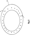
- This can be done by generating sample points for a model, namely an elliptical torus model 50 of the steering wheel 14 (cf. Fig. 2 ), the torus model 50 being positioned according to the sample.
- Corresponding sample pixels of the image are then identified and the rating function is computed on the basis of the pixel values of the sample pixels. More details of this step will be addressed further below.
- new samples are drawn from the samples of the first iteration with a probability that is proportional to the values of the rating function of the samples from the first iteration.
- Each or at least some of the new samples is slightly modified by adding small random values to its position and orientation. These random values are chosen from a Gaussian distribution with a standard deviation that is individually set for each dimension of the position and orientation in proportion to the size of the search space in that dimension. It is preferably enforced that the new samples stay within the search space.
- the rating function is calculated again based on the depth values of the image. This process is repeated iteratively in the same manner, and with each iteration the standard deviations of the added random values are slightly reduced until they are at a tenth of their start value (simulated annealing). This effectively causes the samples to concentrate around those positions and orientations where the torus model 50 appears to fit well to the image. To increase the focus on the best result, one percent of the new samples is not drawn at random but created from the best result of the last iteration.
- the random values that are added only have a hundredth of the usual standard deviation. Additionally (or alternatively), samples can be set to fixed values that cover the complete search space in regular intervals or uniformly at random.
- the steering wheel position can usually be modified by the driver. Therefore, there is a range or number of possible positions and orientations of the steering wheel 14 relative to the first sensor 10. Knowledge about this range can be taken into account to constrain the search space further.
- the depth values of the image are clamped to a predetermined range and then filtered over time to reduce noise.
- the filtering can be carried out on the basis of a sequence of images captured at subsequent time instances.
- a Sobel-edge filter is applied to the filtered image.
- the resulting edge image is clamped to reduce the effect of outliers and to avoid overrating of very steep edges compared to moderate ones.
- the rating function for the sampled steering wheel positions and orientations is calculated using the depth image, the edge image, and a model of the steering wheel 14.
- the model is preferably an elliptical torus 50, Fig. 2 , i.e. a surface consisting of all the points that have a certain distance rto an ellipse in 3D space.
- the length of the major and minor axis of the ellipse and the radius r are fixed and set to values that approximate the shape of the outer ring of the actual steering wheel 14 as seen by the first sensor 10 (which is known a priori).
- the torus 50 is a three-dimensional geometrical model positioned in a three-dimensional space although Fig. 2 shows the torus 50 only in two dimensions.
- a plurality of points are determined for the purpose of evaluating the rating function for the respective sample.
- Each of the points is associated with a depth value. Due to the position and orientation of the model 50 the model 50 has a shape that depends on the perspective of the sensor 10. An example of such a shape is illustrated by the torus 50 of Fig. 2 .
- a fixed number of points a are sampled from the 3D ellipse spanning the torus 50 (cf. Fig. 2 ). For each or at least some of these points a , the local direction of the ellipse is approximated by subtracting its direct neighbours. For a given sample point a1 of the points a, cf. Fig. 3 showing a portion of the torus 50 of Fig. 2 , two points e1 and e2 are determined that lie on the edge 52 of the torus 50 as seen from the point of view of the sensor 10. The direction from a1 to the edge 52 is given by the cross product of the local direction of the ellipsis with the direction from the sensor 10 position to a1 .
- the 3D positions of the said sample points a are calculated, and with them their respective edge points e1, e2 and points a2 outside the torus 50, as shown in an exemplary manner in Fig. 3 for the point a1. All or at least some of the points are then projected from 3D coordinates to pixel coordinates of the depth image using a predetermined transformation rule.
- the transformation rule can be based on intrinsic parameters of the sensor 10, i.e. prior knowledge about the spatial relationship between 3D points in the field of view of the sensor 10 and the resulting pixel information of the image can be available.
- a2 - a1 For each point on the model 50 (i.e. points a, a1) and its corresponding points outside the model 50 (a2), their depth values are subtracted, i.e. a2 - a1.
- the resulting depth differences can be clamped to a predefined range of values, e.g. a range between zero and a fixed value, in order to prevent an overly strong influence of implausible depth differences. This is because it can be assumed that the steering wheel 14 is closer to the sensor 10 than the background around the steering wheel 14 except possibly hands and arms of the driver.
- the rating function can have two components, (i) the sum of the depth differences for all sample points (i.e. a2 - a1 for all a) and (ii) the sum of the edge values of the edge image for all sample positions (i.e. e1 + e2 for all a). Both components can then be added with weights. The result can be normalized and subjected to the exponential function so as to obtain the final result of the rating function for the respective sample location (i.e., the sample position and orientation of the model 50).
- the rating function is computed as set forth above.
- the different results of the rating function are then compared in order to localize the steering wheel 14.
- the maximum of the different results can be chosen and the respective position and orientation of the model 50 is the location of the steering wheel 14.
- a weighted or unweighted average of the different results or a subset of thereof with a high rating can be determined and used to determine the position and orientation of the model 50 matching with the steering wheel 14.
- the rating function can also be formulated in a way that the minimum of the different results of the rating function indicates the location of the steering wheel 14.
- a housing of the steering wheel column 15, a horn plate of the steering wheel 14, an airbag plate, and/or a housing of the second sensor 20 can be used the same way, wherein the shape of the model 50 can be adapted to the outer shape of said elements accordingly.
- the shape of said elements can be reduced to a basic geometrical model and then be applied to the same algorithm.
- the steering wheel 14 or another moveable element to be localized can be provided with a reflective coating in order to increase the signal-to-noise ratio of the image with respect to the element.
- a circle can be provided on a cover of the second sensor 20 which is visible to the first sensor 10 (the first sensor 10 can be an infrared camera and the circle can be adapted to reflect infrared radiation).
- the complete cover or housing of the first sensor can be provided with a reflective coating so as to enhance the accuracy and efficiency of the described localizing algorithm.
- the reflective coating can be adapted so as to reflect only infrared light so that the reflected radiation will be invisible for human eyes.
- mounting tolerances of the first sensor 10 can be taken into consideration when localizing the second sensor 20.
- the mounting position can vary due to manufacturing and temperature.
- the first sensor 10 can localize itself by means of the method described herein.
- a static element in the field of view 12 of the first sensor 10 can be localized, wherein the static element has a fixed default spatial relationship with the first sensor 10.
- the static element can be for example a part of the plastics of the dashbord or center stack of the vehicle. In principle, parts of the window rims can be also be used.
- a deviation from the default position can then be determined and used to update the location of the first sensor 10.
- the location of the first sensor 10 can then be used to more reliably localize the second sensor 20 by means of the first sensor 10.
- alternative methods include model fitting using least-squares techniques. Such methods typically require a good initialization, which can be a disadvantage in a comparison with the particle-filter approach, which is capable of localizing the steering wheel 14 without a strong prior.
- a deep neural network can also be trained to localize the steering wheel 14 on the basis of the image.
- the 3D-coordinates of the steering wheel 14 are directly derived using the neural network.
- the network performs a semantic segmentation, e.g. all pixels in the image belonging to the steering wheel 14 (projection on the image plane) are identified. The information of these pixels can then be used to localize the steering wheel 14 using the particle-filter approach with an increased accuracy and/or efficiency.
- a neural network approach requires sufficient training data, i.e. images of the steering wheel 14 in different positions and orientations.
- the advantage of the particle-filter approach is that it can be easily parametrized to work with different camera types, camera positions and steering wheel shapes, without requiring to collect training data.
Landscapes
- Engineering & Computer Science (AREA)
- Physics & Mathematics (AREA)
- Theoretical Computer Science (AREA)
- General Physics & Mathematics (AREA)
- Multimedia (AREA)
- Signal Processing (AREA)
- General Health & Medical Sciences (AREA)
- General Engineering & Computer Science (AREA)
- Biophysics (AREA)
- Computational Linguistics (AREA)
- Data Mining & Analysis (AREA)
- Evolutionary Computation (AREA)
- Artificial Intelligence (AREA)
- Molecular Biology (AREA)
- Computing Systems (AREA)
- Biomedical Technology (AREA)
- Life Sciences & Earth Sciences (AREA)
- Mathematical Physics (AREA)
- Software Systems (AREA)
- Health & Medical Sciences (AREA)
- Computer Vision & Pattern Recognition (AREA)
- Mechanical Engineering (AREA)
- Image Analysis (AREA)
- Image Processing (AREA)
Abstract
Description
- The invention relates to a method and a device for localizing a sensor in a vehicle by using another sensor.
- Technology advances of recent driver assistance systems lead to an increased degree of automation in vehicles for the mass market. The human driver can hand over the control of the vehicle to a "steering computer" or the like in certain circumstances and scenarios. Today the driver is still fully responsible for the driving task. Even with higher levels of automation, the human driver will remain responsible for monitoring the vehicle and, if required, has to be able to regain the control in a reasonable amount of time.
- Camera-based driver-monitoring systems have been developed to monitor the driver's eyes and head pose to derive information about the awareness or drowsiness of the driver. Other applications of such camera systems include the computation of eye gaze, i.e. where the driver is looking at. Such information is not only relevant for safety, but also for comfort features, such as selecting content on an infotainment system just by looking at things. Such camera-based systems require a camera or another sensor to be mounted on the vehicle.
- A common mounting position of such a camera or other sensor is on the steering wheel column. This position offers a good view on the driver's face and eyes. However, as the steering wheel position and/or the steering wheel column can be adjusted to fit different driver sizes and preferences, the camera can be moveable together with the steering wheel column. For example, the steering wheel and the steering wheel column can be adjusted electronically or mechanically in forward/backward and/or upward/downward directions.
- For various applications the relative and/or absolute position of the camera and/or its orientation within the car are required in order to map objects from a camera coordinate system to a vehicle coordinate system. One example is the accurate localization of the driver's head position with respect to the vehicle coordinate system, e.g. in the context of eye gaze. In other words, the location of the camera needs to be known in order to reliably derive spatial, i.e. positional data from the images which are captured by means of the camera. If the camera location is not known the spatial data can only be determined relative to the camera, but not in relation to other coordinate systems or elements. For example, the viewing direction of a person cannot be precisely matched with elements inside or outside the car without having reliable information about the sensor position and/or orientation.
- In light of the foregoing it is desired to provide a method for localizing the camera. In particular, the camera may be localized with respect to a target coordinate system which is independent from the coordinate system of the camera. The target coordinate system can be, for example, a vehicle coordinate system. When the location of the camera is known spatial data can be precisely determined on the basis of images captured by the camera, for example the eye gaze and the position and/or orientation of the driver's head.
- Some vehicles allow for an electronic adjustment of the steering wheel, while others have a purely mechanical mechanism to change the angle and distance of the steering wheel. While in the first approach it is theoretically possible to monitor the electronic adjustments and translate them into a change of the camera position from a reference position, in practice such information is not available in many cars (e.g. on the CAN bus). For example, one might only obtain the information that the steering wheel has been adjusted, however, not by how much. In the purely mechanical version, there is no such information at all.
- A solution is needed for reliably localizing a sensor mounted on a vehicle.
- The present disclosure provides subject-matters laid down in the independent claims. Advantageous further developments and aspects are set forth in the dependent claims.
- In one aspect a method for localizing a sensor in a vehicle is provided, the method comprising at least the following steps: capturing, by means of a first sensor being mounted on a vehicle, at least one image of a moveable element of the vehicle, the moveable element having a predetermined spatial relationship to a second sensor being mounted on the vehicle, the moveable element being moveable relative to the first sensor; determining a spatial information on the moveable element on the basis of the at least one image; and localizing the second sensor on the basis of the spatial information by means of a transformation rule, the transformation rule representing the predetermined spatial relationship between the moveable element and the second sensor.
- Localizing of the second sensor can generally comprise two steps, i.e. a first step and a second step.
- In a first step spatial information on the moveable element is determined based on image data. The spatial information can be, e.g., a position and/or orientation of the moveable element with respect to a coordinate system of the vehicle. The spatial information may thus be denoted as absolute spatial information. Since the spatial information is determined on the basis of an image captured by the first sensor, the spatial information may be transformed from the coordinate system of the first sensor to a coordinate system of the vehicle by using a predetermined second transformation rule. However, it can also be provided that the spatial information is directly determined, i.e. without transforming the data from a sensor coordinate system of the first sensor to the vehicle coordinate system. Algorithms for determining spatial information from images are generally known from the art, for example from neural network technology. Specific embodiments will be explained in more detail further below.
- In a second step the location of the second sensor is determined on the basis of the spatial information by means of said (first) transformation rule. This transformation rule describes the spatial relationship between the moveable element and the second sensor. This spatial relationship is preferably fixed, i.e. the moveable element and the second sensor can only be moved together without changing the position and orientation between the element and the sensor. Therefore, the transformation rule can also be fixed, for example in form of a transformation matrix having fixed values. However, as the case may be, the spatial relationship can be variable so that the transformation rule can have various forms. Nevertheless, the spatial relationship is predetermined, i.e. known a-priori. The transformation rule or parameters thereof can thus be stored before carrying out the method.
- One advantage of the method is its high flexibility. It can be applied to virtually any configuration inside a vehicle and a physical measurement of the spatial information, e.g., by acceleration sensors is not required. Therefore, the method can easily be adapted to different types of vehicles. As another advantage the first sensor can also be used for other purposes, for example for monitoring portions of the vehicle other than the moveable element. The hardware required for carrying out the method can thus be used in a synergistic way.
- According to a further aspect the method comprises matching a geometrical model of the moveable element to the at least one image by using a matching algorithm, wherein the spatial information is determined on the basis of the matched model, i.e. the model being matched to the moveable element by means of the matching algorithm. The matching can be a fitting of a predetermined geometrical model comprising an iterative evaluation of a cost function or other rating function that represents the accordance between the model and the true moveable element captured in the image. The matching can comprise positioning of the geometrical model at a plurality of sample positions and/or orientations, wherein the cost function is computed for each of the sample positions and/or orientations. A maximum of the cost function can then be used to identify the matched model.
- The geometrical model generally represents the moveable element. For example, the model or the outer shape of the model can be represented by a mathematical function, which is a very compact representation and therefore associated with a number of advantages. The model can also be represented by a limited number of points in order to reduce the complexity of the method.
- Said matching algorithm preferably comprises or is configured as a particle algorithm, a grid-search algorithm and/or a regression algorithm. These types of algorithms are generally known from the art.
- The matching step can comprise the following: generating a plurality of sample points for the geometrical model, each of the sample points having a spatial position; determining, for at least some of the sample points, a plurality of sample pixels of the at least one image, each of the sample pixels having a respective pixel value of the at least one image; computing a rating function on the basis of the sample pixels, i.e. their pixel values; determining the matched model on the basis of the rating function. It is understood that the at least one image comprises a plurality of pixels, each of the pixels having a respective pixel value. The sample pixels are a subset of the totality of pixels that form the at least one image.
- In one example the moveable element is formed by a steering wheel. Said model of the moveable element can then be, e.g., a torus, in particular an elliptical torus. To estimate the spatial information, e.g. 3D position and orientation (pose), possible locations can be sampled by using a regular-grid search and/or a particle-filter like approach. For each possible sample location, the rating function can be calculated based on a specific portion of pixel values of the at least one image, these pixels can be selected on the basis of the generated sample points, as indicated further above. The rating function can generally represent the match between the model at the respective sample location and the image.
- Having further regard to said generated sample points for identifying the sample pixel values, a first group of the sample points can be located on the geometrical model, and a second group of the sample points can be located outside the geometrical model, wherein difference pixel values can be computed between sample points of the first and second group. This can be done by subtracting pixel values of the sample pixels being associated with the sample points. In particular, each difference pixel value can be formed by subtracting a pixel value from the first group from a pixel value of the second group, wherein both pixel values are associated with a pair of sample pixels positioned on a line that extends in a radial direction or transversely with respect to the model. The rating function can be computed on the basis of the difference pixel values, which allows determining the spatial information with high accuracy.
- In one example the values of the first group can be depth (i.e. distance) values of sample points located centrally on the model. In addition or alternatively, depth values of image points located on the outer edge of the model can be used. The values of the second group can be the depth values of the sample points located outside the model. The values of some points of the first group, for example the points located on the edges, can be gradients of the depth values, wherein these gradients result from processing the depth values by an edge detection filter, e.g. a Sobel edge filter. Exemplary algorithmic details are described further below.
- According to another aspect the method further comprises processing of the at least one image or a portion thereof by means of a neural network for obtaining an output, wherein the spatial information is determined on the basis of the output. The neural network is preferably formed by a convolutional neural network. The use of a neural network can be an alternative to the use of a matching algorithm. However, a combination is also possible, wherein the spatial information can be determined on the basis of the output of the neural network and the matched model, for example by fusing the two results. It is also possible that the output of the neural network is used as a prior (i.e. prior probability distribution) for the matching algorithm, e.g. for example by constraining the search space of a particle algorithm. As an alternative the spatial information from the particle algorithm can be used to roughly localize the moveable element, wherein the roughly determined location is then used for determining an image portion of the moveable element by cropping the image to the moveable element including a margin. The image portion can then be processed by the neural network for obtaining the output.
- According to another aspect the at least one image comprises three-dimensional (3D) image data. The first sensor can thus comprise a time-of-flight camera, an ultrasonic sensor, a radar sensor, a structured light camera and/or a Lidar sensor. Other sensors for acquiring three-dimensional image data can also be used, in particular multiple sensors, e.g. a stereoscopic sensor pair.
- The spatial information on the moveable element can comprise a position and/or an orientation, e.g. an angle of the moveable element. The spatial information can be provided with respect to a predetermined coordinate system, in particular a coordinate system of the vehicle.
- According to another aspect the moveable element comprises at least a portion of one of the following: a steering element of the vehicle, a housing of the second sensor, a steering element column of the vehicle, a headrest of a vehicle seat. The steering element can be a steering wheel or the like.
- According to yet another aspect the first sensor is mounted on one of the following portions of the vehicle: an inner side of a roof, a pillar of a vehicle body (e.g., A or B pillar), a headrest of a seat (e.g., the seat of the driver), a seat backrest.
- In general, the moveable element can be moveable relative to the first sensor essentially only due to an adjustment of the driver or another person. This adjustment can be carried out manually or electronically.
- In one embodiment the second sensor is mounted on a steering wheel column of the vehicle, wherein the steering wheel column is moveable relative to the first sensor and comprising the moveable element. In addition the second sensor can be configured to take images of a vehicle seat in which a passenger's body or a portion thereof is expected to be located when the passenger is sitting on the vehicle seat.
- The moveable element can comprise a reflective surface. In this way, the spatial information can be determined with an increased reliability. The reflective properties of the surface can be adapted to the first sensor. This is to say that the first sensor can be configured to detect the reflective properties, thereby improving the detection of the moveable element. The reflective properties can be adapted to increase the ratio of pixel values from pixels located on the reflective surface relative to pixel values from pixels located outside the reflective surface. This can be interpreted as a way to improve the signal-to-noise ratio.
- The reflective properties of the reflective surface can be limited to a range of wavelengths, wherein the range is adapted to the sensitivity of the first sensor. In one example, radiation having a wavelength within said range can essentially be invisible to human eyes. For example, the range of wavelengths can be defined in accordance to the wavelengths of infrared radiation.
- According to another aspect a device for localizing a sensor in a vehicle is provided. The device comprises an input for receiving at least one image captured by a first sensor and a processing unit (comprising, e.g. a processor and a memory). The processing unit is configured to determine a location of a second sensor by carrying out at least one of the methods disclosed herein. The processing unit can be further configured to process images captured by the second sensor with respect to the location of the second sensor. The location of the second sensor can thus be used for calibrating the operation of the second sensor. In this way, absolute spatial information can be derived from the images of the second sensor because the second sensor knows its location with respect to the "absolute" coordinate system, which can be a vehicle coordinate system. As an alternative, the processing unit can have an output for outputting the location of the second sensor to another processing unit, which is connected to the second sensor and configured to process images captured by the second sensor with respect to the location of the second sensor. One or both of said processing units may comprise at least one memory unit and at least one non-transitory data storage. The non-transitory data storage and/or the memory unit may comprise a computer program for instructing the computer to perform several or all steps or aspects of the computer implemented method described herein.
- According to another aspect a non-transitory computer readable medium is provided. It comprises instructions, which when executed by a processing unit (in particular one of said processing units), cause the processing unit to carry out the method as described herein. The computer readable medium may be configured as: an optical medium, such as a compact disc (CD) or a digital versatile disk (DVD); a magnetic medium, such as a hard disk drive (HDD); a solid state drive (SSD); a read only memory (ROM), such as a flash memory; or the like. Furthermore, the computer readable medium may be configured as a data storage that is accessible via a data connection, such as an internet connection. The computer readable medium may, for example, be an online data repository or a cloud storage.
- A system comprises the device as described further above, wherein the system comprises a first sensor and a second sensor, and wherein at least the first sensor is connected to the device. If the processing unit of the device is configured to output the location of the second sensor to another processing unit then the second sensor is preferably connected to the other processing unit. If only one processing unit is used which is configured to determine the location and to process the images of the second sensor then the second sensor is preferably connected to this processing unit.
- It is understood that features described in connection with the method can be realized in the device as well as the system and vice versa.
- Exemplary embodiments and functions of the present disclosure will be described in more detail in the following with reference to the drawings which show in:
- Fig. 1
- a schematic illustration of a system for localizing a sensor in a vehicle;
- Fig. 2
- a schematic illustration of a model representing a steering element in an image; and
- Fig. 3
- a schematic illustration of a portion of the model of
Fig. 2 . - In the figures, the same or corresponding parts are indicated with the same reference signs.
-
Fig. 1 illustrates aspects of a system for carrying out a method for localizing asecond sensor 20 by using afirst sensor 10. Thefirst sensor 10 is mounted on a vehicle (not shown) such that a field ofview 12 of thesensor 10 captures asteering wheel 14 of the vehicle. Thesensor 10 can be mounted inside a passenger cabin of the vehicle (not shown), for example at the inside of a roof of the cabin. Thesensor 10 can be a camera for capturing images of the field ofview 12, wherein the camera can be configured to provide three-dimensional images, for example when the camera is a time-of-flight camera. - The
second sensor 20 is mounted on asteering wheel column 15 of the vehicle at a predetermined position. Thesteering wheel column 15 can be adjusted to various positions, wherein thesecond sensor 20 is usually only moveable together with thesteering wheel column 15. - The spatial relationship between the
steering wheel 14 and thesecond sensor 20 is preferably fixed, i.e. thesteering wheel 14 is only moveable together with thesteering wheel column 15. Thesteering wheel 14 does not necessarily need to be mechanically connected to a portion of thesteering wheel column 15 on which thesecond sensor 20 is mounted. For example thesecond sensor 20 can be mounted on a housing of thesteering wheel column 15. However, the spatial relationship between thesteering wheel 14 and thesecond sensor 20 is at least predetermined, i.e. known a-priori. Therefore, thesteering wheel 14 can also be moveable relative to thesecond sensor 20 if the spatial relationship remains to be known. - It is preferred that adjustments of the
steering wheel column 15 do not lead a displacement of thesteering wheel 14 beyond the field ofview 12. Therefore, each of the images captured by thefirst sensor 10 includes thesteering wheel 14, at least partially. Preferably, thefirst sensor 10 is arranged such that thesteering wheel 14 is always contained in the images captured by thefirst sensor 10. - The
first sensor 10 is connected to aprocessing unit 16, which is configured to carry out a computer-implemented method for localizing asecond sensor 20 by means of thefirst sensor 10. This will be described in greater detail in the following. - The method begins with capturing at least one image (not shown) by means of the
first sensor 10. The image is then processed by means of theprocessing unit 16 for determining the location, e.g. position and/or orientation of thesecond sensor 20. - In one aspect of the method the
steering wheel 14 is detected within the image by localizing thesteering wheel 14 within the image. This can be done by using a particle-filter algorithm. In particular, the 3D position and orientation of thesteering wheel 14 can be determined based on amplitude (intensity) and/or depth data of the image, wherein thefirst sensor 10 can be a time-of-flight camera mounted inside the vehicle, as indicated further above. This is to say that the image comprises three-dimensional image data. Alternatively, 2D-image data can be used. - As an initial step for localizing the steering wheel 14 a fixed number of samples for the position and orientation of the
steering wheel 14 are drawn uniformly (or according to normal distributions centered at the last known position(s) of thesteering wheel 14 or at the center of the range of possible positions of the steering wheel 14) at random within a predefined search space. In a first iteration, a rating function is calculated for each of the samples, wherein the rating function quantifies the accordance, i.e. match of the sample with the depth values of the image. This can be done by generating sample points for a model, namely anelliptical torus model 50 of the steering wheel 14 (cf.Fig. 2 ), thetorus model 50 being positioned according to the sample. Corresponding sample pixels of the image are then identified and the rating function is computed on the basis of the pixel values of the sample pixels. More details of this step will be addressed further below. - For the next iteration, new samples are drawn from the samples of the first iteration with a probability that is proportional to the values of the rating function of the samples from the first iteration. Each or at least some of the new samples is slightly modified by adding small random values to its position and orientation. These random values are chosen from a Gaussian distribution with a standard deviation that is individually set for each dimension of the position and orientation in proportion to the size of the search space in that dimension. It is preferably enforced that the new samples stay within the search space.
- For each of the redrawn samples of the next iteration the rating function is calculated again based on the depth values of the image. This process is repeated iteratively in the same manner, and with each iteration the standard deviations of the added random values are slightly reduced until they are at a tenth of their start value (simulated annealing). This effectively causes the samples to concentrate around those positions and orientations where the
torus model 50 appears to fit well to the image. To increase the focus on the best result, one percent of the new samples is not drawn at random but created from the best result of the last iteration. Here, the random values that are added only have a hundredth of the usual standard deviation. Additionally (or alternatively), samples can be set to fixed values that cover the complete search space in regular intervals or uniformly at random. - The steering wheel position can usually be modified by the driver. Therefore, there is a range or number of possible positions and orientations of the
steering wheel 14 relative to thefirst sensor 10. Knowledge about this range can be taken into account to constrain the search space further. - Details of the
torus model 50 and the rating function are further described in the following. - The depth values of the image (the depth values form a depth image) are clamped to a predetermined range and then filtered over time to reduce noise. The filtering can be carried out on the basis of a sequence of images captured at subsequent time instances. A Sobel-edge filter is applied to the filtered image. The resulting edge image is clamped to reduce the effect of outliers and to avoid overrating of very steep edges compared to moderate ones. The rating function for the sampled steering wheel positions and orientations is calculated using the depth image, the edge image, and a model of the
steering wheel 14. - As also indicated further above the model is preferably an
elliptical torus 50,Fig. 2 , i.e. a surface consisting of all the points that have a certain distance rto an ellipse in 3D space. The length of the major and minor axis of the ellipse and the radius r are fixed and set to values that approximate the shape of the outer ring of theactual steering wheel 14 as seen by the first sensor 10 (which is known a priori). It is understood that thetorus 50 is a three-dimensional geometrical model positioned in a three-dimensional space althoughFig. 2 shows thetorus 50 only in two dimensions. - For a given sample (position and orientation) of the model 50 a plurality of points (i.e. sample points) are determined for the purpose of evaluating the rating function for the respective sample. Each of the points is associated with a depth value. Due to the position and orientation of the
model 50 themodel 50 has a shape that depends on the perspective of thesensor 10. An example of such a shape is illustrated by thetorus 50 ofFig. 2 . - A fixed number of points a are sampled from the 3D ellipse spanning the torus 50 (cf.
Fig. 2 ). For each or at least some of these points a, the local direction of the ellipse is approximated by subtracting its direct neighbours. For a given sample point a1 of the points a, cf.Fig. 3 showing a portion of thetorus 50 ofFig. 2 , two points e1 and e2 are determined that lie on theedge 52 of thetorus 50 as seen from the point of view of thesensor 10. The direction from a1 to theedge 52 is given by the cross product of the local direction of the ellipsis with the direction from thesensor 10 position to a1. By moving along that direction, starting at a1, over a distance of the torus radius r into both directions, the two edge points e1 and e2are obtained. Following that direction further than r into the direction that leads away from the center of the ellipse, a point a2 outside the torus is calculated. - For a given sample position and orientation for the
torus 50 the 3D positions of the said sample points a, are calculated, and with them their respective edge points e1, e2 and points a2 outside thetorus 50, as shown in an exemplary manner inFig. 3 for the point a1. All or at least some of the points are then projected from 3D coordinates to pixel coordinates of the depth image using a predetermined transformation rule. The transformation rule can be based on intrinsic parameters of thesensor 10, i.e. prior knowledge about the spatial relationship between 3D points in the field of view of thesensor 10 and the resulting pixel information of the image can be available. - Using the depth image, for each point on the model 50 (i.e. points a, a1) and its corresponding points outside the model 50 (a2), their depth values are subtracted, i.e. a2 - a1. The resulting depth differences can be clamped to a predefined range of values, e.g. a range between zero and a fixed value, in order to prevent an overly strong influence of implausible depth differences. This is because it can be assumed that the
steering wheel 14 is closer to thesensor 10 than the background around thesteering wheel 14 except possibly hands and arms of the driver. - The rating function can have two components, (i) the sum of the depth differences for all sample points (i.e. a2 - a1 for all a) and (ii) the sum of the edge values of the edge image for all sample positions (i.e. e1 + e2 for all a). Both components can then be added with weights. The result can be normalized and subjected to the exponential function so as to obtain the final result of the rating function for the respective sample location (i.e., the sample position and orientation of the model 50).
- For at least some of the possible sample locations of the
model 50 the rating function is computed as set forth above. The different results of the rating function are then compared in order to localize thesteering wheel 14. For example, the maximum of the different results can be chosen and the respective position and orientation of themodel 50 is the location of thesteering wheel 14. Alternatively, a weighted or unweighted average of the different results or a subset of thereof with a high rating (above a threshold) can be determined and used to determine the position and orientation of themodel 50 matching with thesteering wheel 14. It is understood that the rating function can also be formulated in a way that the minimum of the different results of the rating function indicates the location of thesteering wheel 14. - It is understood that instead of the steering wheel 14 a housing of the
steering wheel column 15, a horn plate of thesteering wheel 14, an airbag plate, and/or a housing of thesecond sensor 20 can be used the same way, wherein the shape of themodel 50 can be adapted to the outer shape of said elements accordingly. This is to say that the shape of said elements can be reduced to a basic geometrical model and then be applied to the same algorithm. - The
steering wheel 14 or another moveable element to be localized can be provided with a reflective coating in order to increase the signal-to-noise ratio of the image with respect to the element. For example a circle can be provided on a cover of thesecond sensor 20 which is visible to the first sensor 10 (thefirst sensor 10 can be an infrared camera and the circle can be adapted to reflect infrared radiation). In another example the complete cover or housing of the first sensor can be provided with a reflective coating so as to enhance the accuracy and efficiency of the described localizing algorithm. The reflective coating can be adapted so as to reflect only infrared light so that the reflected radiation will be invisible for human eyes. - In a further aspect mounting tolerances of the
first sensor 10 can be taken into consideration when localizing thesecond sensor 20. For example, the mounting position can vary due to manufacturing and temperature. In order to avoid an error due to such mounting tolerances thefirst sensor 10 can localize itself by means of the method described herein. For example, instead of asteering wheel 14 or other moveable element a static element in the field ofview 12 of thefirst sensor 10 can be localized, wherein the static element has a fixed default spatial relationship with thefirst sensor 10. The static element can be for example a part of the plastics of the dashbord or center stack of the vehicle. In principle, parts of the window rims can be also be used. A deviation from the default position can then be determined and used to update the location of thefirst sensor 10. The location of thefirst sensor 10 can then be used to more reliably localize thesecond sensor 20 by means of thefirst sensor 10. - As an alternative to the particle-filter approach set forth above alternative methods include model fitting using least-squares techniques. Such methods typically require a good initialization, which can be a disadvantage in a comparison with the particle-filter approach, which is capable of localizing the
steering wheel 14 without a strong prior. - A deep neural network can also be trained to localize the
steering wheel 14 on the basis of the image. In one variant the 3D-coordinates of thesteering wheel 14 are directly derived using the neural network. In another variant the network performs a semantic segmentation, e.g. all pixels in the image belonging to the steering wheel 14 (projection on the image plane) are identified. The information of these pixels can then be used to localize thesteering wheel 14 using the particle-filter approach with an increased accuracy and/or efficiency. - A neural network approach requires sufficient training data, i.e. images of the
steering wheel 14 in different positions and orientations. The advantage of the particle-filter approach is that it can be easily parametrized to work with different camera types, camera positions and steering wheel shapes, without requiring to collect training data. - It is understood that while the method described herein are primarily described for the case of a single
first sensor 10 more than one first sensor can be used to localize thesecond sensor 20 in the same manner, wherein a fusion of the different results can be adopted, thus enhancing availability and/or accuracy of the desired information. -
- 10
- first sensor
- 12
- field of view
- 14
- steering wheel
- 15
- steering wheel column
- 16
- first processing unit
- 18
- second processing unit
- 20
- second sensor
- 50
- elliptical torus
- 52
- edge
- a, a1
- point on torus
- a2
- point outside torus
- e1, e2
- points on torus edge
- r
- radius
Claims (15)
- A method for localizing a sensor in a vehicle, the method comprising:- capturing, by means of a first sensor (10) being mounted on a vehicle, at least one image of a moveable element (14) of the vehicle,
the moveable element (14) having a predetermined spatial relationship to a second sensor (20) being mounted on the vehicle, the moveable element (14) being moveable relative to the first sensor (10);- determining a spatial information on the moveable element (14) on the basis of the at least one image; and- localizing the second sensor (20) on the basis of the spatial information by means of a transformation rule, the transformation rule representing the predetermined spatial relationship between the moveable element (14) and the second sensor (20). - The method of one of the preceding claims,
further comprising matching a geometrical model (50) of the moveable element (14) to the at least one image by using a matching algorithm, wherein the spatial information is determined on the basis of the matched model (50), and
wherein the matching algorithm preferably comprises a particle algorithm, a grid-search algorithm and/or a regression algorithm. - The method of claim 2,
wherein the matching comprises:- generating a plurality of sample points (a, a1, a2, e1, e2) for the geometrical model (50), each of the sample points (a, a1, a2, e1, e2) having a spatial position;- determining, for at least some of the sample points (a, a1, a2, e1, e2), a plurality of sample pixels of the at least one image, each of the pixels having a respective pixel value;- computing a rating function on the basis of the sample pixels;- determining the matched model (50) on the basis of the rating function. - The method according to claim 3,
wherein a first group of the sample points (a, a1, e1, e2) are located on the model (50), and a second group of the sample points (e2) are located outside the model (50), wherein difference pixel values are computed for sample points between the first and second group, and wherein the rating function is computed on the basis of the difference values. - The method according to one of the preceding claims,
further comprising processing of the at least one image or a portion thereof by means of a neural network for obtaining an output,
wherein the spatial information is determined on the basis of the output. - The method according to one of the preceding claims,
wherein the at least one image comprises three-dimensional image data. - The method according to one of the preceding claims,
wherein the spatial information comprises a position and/or an orientation of the moveable element (14). - The method according to one of the preceding claims,
wherein the moveable element comprises at least a portion of one of the following:- a steering element (14) of the vehicle,- a housing of the second sensor (20),- a steering element column (15) of the vehicle,- a headrest of a vehicle seat. - The method according to one of the preceding claims,
wherein the first sensor (10) is mounted on one of the following portions of the vehicle:- an inner side of a roof,- a pillar of a vehicle body,- a headrest of a seat,- a seat backrest. - The method according to one of claims 1 to 7,
wherein the second sensor (20) is mounted on a steering wheel column (15) of the vehicle, the steering wheel column (15) being moveable relative to the first sensor (10) and comprising the moveable element (14), wherein the second sensor (20) is configured to take images of a vehicle seat in which a passengers body or a portion thereof is expected to be located when the passenger is sitting on the vehicle seat. - The method according to one of the preceding claims,
wherein the moveable element (14) comprises a reflective surface having reflective properties being adapted to the first sensor (10). - The method according to claim 11,
wherein the reflective properties are limited to a range of wavelengths being invisible to human eyes. - A device for localizing a sensor in a vehicle, the device comprising:- an input for receiving at least one image captured by a first sensor (10),- a processing unit (16, 18) configured to determine a location of a second sensor (20) by carrying out the method according to at least one of the preceding claims, wherein the processing unit (16, 18) is further configured to process images captured by the second sensor (20) with respect to the location of the second sensor (20) or to output the location.
- A non-transitory computer readable medium comprising instructions, which when executed by a processing unit (16, 18), cause the processing unit (16, 18) to carry out the method of one of claims 1 to 12.
- A system comprising the device according to claim 13,
wherein the system comprises a first sensor (10) and a second sensor (20), wherein at least the first sensor (10) is connected to the device (16).
Priority Applications (3)
| Application Number | Priority Date | Filing Date | Title |
|---|---|---|---|
| EP19167433.2A EP3719696A1 (en) | 2019-04-04 | 2019-04-04 | Method and device for localizing a sensor in a vehicle |
| CN202010161041.4A CN111795641B (en) | 2019-04-04 | 2020-03-10 | Method and apparatus for locating sensors in a vehicle |
| US16/816,705 US11138753B2 (en) | 2019-04-04 | 2020-03-12 | Method and device for localizing a sensor in a vehicle |
Applications Claiming Priority (1)
| Application Number | Priority Date | Filing Date | Title |
|---|---|---|---|
| EP19167433.2A EP3719696A1 (en) | 2019-04-04 | 2019-04-04 | Method and device for localizing a sensor in a vehicle |
Publications (1)
| Publication Number | Publication Date |
|---|---|
| EP3719696A1 true EP3719696A1 (en) | 2020-10-07 |
Family
ID=66092258
Family Applications (1)
| Application Number | Title | Priority Date | Filing Date |
|---|---|---|---|
| EP19167433.2A Pending EP3719696A1 (en) | 2019-04-04 | 2019-04-04 | Method and device for localizing a sensor in a vehicle |
Country Status (3)
| Country | Link |
|---|---|
| US (1) | US11138753B2 (en) |
| EP (1) | EP3719696A1 (en) |
| CN (1) | CN111795641B (en) |
Citations (4)
| Publication number | Priority date | Publication date | Assignee | Title |
|---|---|---|---|---|
| US20050077469A1 (en) * | 2002-02-02 | 2005-04-14 | Kaushal Tej Paul | Head position sensor |
| US20150084764A1 (en) * | 2013-09-25 | 2015-03-26 | Denso Corporation | Adaptive instrument display using eye tracking |
| US20150210237A1 (en) * | 2014-01-27 | 2015-07-30 | Lenovo (Singapore) Pte. Ltd. | Airbag adjustment based on driver position |
| EP3040254A1 (en) * | 2013-08-28 | 2016-07-06 | Kyocera Corporation | Turning angle correction method, turning angle correction device, image-capturing device, and turning angle correction system |
Family Cites Families (28)
| Publication number | Priority date | Publication date | Assignee | Title |
|---|---|---|---|---|
| US5724743A (en) * | 1992-09-04 | 1998-03-10 | Snap-On Technologies, Inc. | Method and apparatus for determining the alignment of motor vehicle wheels |
| US20070135982A1 (en) * | 1995-06-07 | 2007-06-14 | Automotive Technologies International, Inc. | Methods for Sensing Weight of an Occupying Item in a Vehicular Seat |
| DE19757763A1 (en) * | 1997-12-23 | 1999-07-01 | Bosch Gmbh Robert | Device for determining the wheel and / or axle geometry of motor vehicles |
| DE19757760A1 (en) * | 1997-12-23 | 1999-07-01 | Bosch Gmbh Robert | Device for determining the wheel and / or axle geometry of motor vehicles |
| AUPP299498A0 (en) * | 1998-04-15 | 1998-05-07 | Commonwealth Scientific And Industrial Research Organisation | Method of tracking and sensing position of objects |
| DE10027922A1 (en) | 2000-06-06 | 2002-01-24 | Bosch Gmbh Robert | Method for detecting the position of hands on a steering wheel |
| US8768286B2 (en) | 2001-10-24 | 2014-07-01 | Mouhamad Ahmad Naboulsi | Hands on steering wheel vehicle safety control system |
| DE102004005380A1 (en) * | 2004-02-03 | 2005-09-01 | Isra Vision Systems Ag | Method for determining the position of an object in space |
| DE102004013441A1 (en) * | 2004-03-18 | 2005-10-13 | Beissbarth Gmbh | Measuring method and measuring device for determining the spatial position of a wheel rim and wheel alignment device |
| WO2007073272A1 (en) * | 2005-12-23 | 2007-06-28 | Gcoder Systems Ab | Positioning pattern |
| DE102005063051A1 (en) * | 2005-12-29 | 2007-07-05 | Robert Bosch Gmbh | Motor vehicle`s e.g. car, chassis measuring method, involves disposing coordinate system for image recording device e.g. camera, and/or measuring unit to determine chassis data of evaluation unit independent of reference objects |
| JP4427759B2 (en) * | 2007-06-29 | 2010-03-10 | アイシン・エィ・ダブリュ株式会社 | Vehicle behavior learning apparatus and vehicle behavior learning program |
| US8564424B2 (en) | 2009-12-07 | 2013-10-22 | Inventioneers Etc., Llc | Steering wheel hand position sensing device |
| GB2506685A (en) * | 2012-10-08 | 2014-04-09 | Melexis Technologies Nv | Determining and/or Compensating Range Offset of a Range Sensor |
| US8825303B1 (en) * | 2013-03-28 | 2014-09-02 | Snap-On Incorporated | Wheel alignment apparatus and method for vehicles having electro-mechanical power steering |
| CN105593659B (en) * | 2013-08-19 | 2019-03-15 | 实耐宝公司 | Improved Motor Control System for Self-Calibrating Multi-Camera Positioning System |
| EP3428766B1 (en) * | 2014-09-05 | 2021-04-07 | SZ DJI Technology Co., Ltd. | Multi-sensor environmental mapping |
| US10445616B2 (en) * | 2015-01-22 | 2019-10-15 | Bae Systems Information And Electronic Systems Integration Inc. | Enhanced phase correlation for image registration |
| JP2018512593A (en) * | 2015-04-10 | 2018-05-17 | ローベルト ボツシユ ゲゼルシヤフト ミツト ベシユレンクテル ハフツングRobert Bosch Gmbh | Object position measurement with in-vehicle camera using vehicle movement data |
| CN107850901B (en) * | 2015-05-23 | 2021-04-16 | 深圳市大疆创新科技有限公司 | Sensor fusion using inertial and image sensors |
| US20170057545A1 (en) * | 2015-08-26 | 2017-03-02 | Delphi Technologies, Inc. | Gps data correction for automated vehicle |
| DE112017001322T5 (en) * | 2016-03-16 | 2018-12-27 | Sony Corporation | Signal processing apparatus and signal processing method |
| US10402675B2 (en) * | 2016-08-30 | 2019-09-03 | The Boeing Company | 2D vehicle localizing using geoarcs |
| DE102016118593A1 (en) * | 2016-09-30 | 2018-04-05 | Dürr Assembly Products GmbH | Device for detecting the steering wheel position, the steering wheel angle and / or the inclination of the steering wheel of a vehicle |
| WO2018125939A1 (en) * | 2016-12-30 | 2018-07-05 | DeepMap Inc. | Visual odometry and pairwise alignment for high definition map creation |
| US10176596B1 (en) * | 2017-07-06 | 2019-01-08 | GM Global Technology Operations LLC | Calibration verification methods for autonomous vehicle operations |
| US10436885B2 (en) * | 2017-10-19 | 2019-10-08 | DeepMap Inc. | Calibrating sensors mounted on an autonomous vehicle |
| US20200202198A1 (en) * | 2018-12-21 | 2020-06-25 | Waymo Llc | Neural network processor |
-
2019
- 2019-04-04 EP EP19167433.2A patent/EP3719696A1/en active Pending
-
2020
- 2020-03-10 CN CN202010161041.4A patent/CN111795641B/en active Active
- 2020-03-12 US US16/816,705 patent/US11138753B2/en active Active
Patent Citations (4)
| Publication number | Priority date | Publication date | Assignee | Title |
|---|---|---|---|---|
| US20050077469A1 (en) * | 2002-02-02 | 2005-04-14 | Kaushal Tej Paul | Head position sensor |
| EP3040254A1 (en) * | 2013-08-28 | 2016-07-06 | Kyocera Corporation | Turning angle correction method, turning angle correction device, image-capturing device, and turning angle correction system |
| US20150084764A1 (en) * | 2013-09-25 | 2015-03-26 | Denso Corporation | Adaptive instrument display using eye tracking |
| US20150210237A1 (en) * | 2014-01-27 | 2015-07-30 | Lenovo (Singapore) Pte. Ltd. | Airbag adjustment based on driver position |
Also Published As
| Publication number | Publication date |
|---|---|
| US11138753B2 (en) | 2021-10-05 |
| US20200320730A1 (en) | 2020-10-08 |
| CN111795641A (en) | 2020-10-20 |
| CN111795641B (en) | 2022-03-18 |
Similar Documents
| Publication | Publication Date | Title |
|---|---|---|
| US11535280B2 (en) | Method and device for determining an estimate of the capability of a vehicle driver to take over control of a vehicle | |
| US11977675B2 (en) | Primary preview region and gaze based driver distraction detection | |
| US11094080B2 (en) | Method and device for determining whether a hand cooperates with a manual steering element of a vehicle | |
| US11572071B2 (en) | Method and system for determining awareness data | |
| JP7498364B2 (en) | Correcting camera images in the presence of rain, light and dirt | |
| CN109633684B (en) | Method, device, machine learning system and machine-readable storage medium for classification | |
| EP3488382A1 (en) | Method and system for monitoring the status of the driver of a vehicle | |
| WO2019102751A1 (en) | Distance measurement device | |
| US11846726B2 (en) | Method and device for identifying objects detected by a LiDAR device | |
| US10752256B2 (en) | Method and device for controlling at least one driver interaction system | |
| US12243321B2 (en) | Method for determining a semantic free space | |
| CN114074607A (en) | Rearview mirror adjusting method and device and vehicle | |
| US12307790B2 (en) | Steering wheel contact detection | |
| CN116805411A (en) | Method for determining the orientation of a camera | |
| US11138753B2 (en) | Method and device for localizing a sensor in a vehicle | |
| EP3786764B1 (en) | Method and localization device for localizing an image sensor mounted on a vehicle | |
| US20240354980A1 (en) | Depth Estimation for Interior Sensing | |
| KR20230096530A (en) | Driving control apparatus and method | |
| JP2022128697A (en) | Gaze detection device | |
| WO2018020044A1 (en) | Method and system for associating data pertaining to the detection and tracking of moving objects for an automotive vehicle | |
| WO2022091620A1 (en) | Object tracking device and object tracking method | |
| CN112581793A (en) | Method for operating a motor vehicle with a stereo camera system and a LIDAR sensor | |
| CN117957464A (en) | Clustering laser scanner scan points | |
| Stoddart | Computer Vision Techniques for Automotive Perception Systems |
Legal Events
| Date | Code | Title | Description |
|---|---|---|---|
| PUAI | Public reference made under article 153(3) epc to a published international application that has entered the european phase |
Free format text: ORIGINAL CODE: 0009012 |
|
| STAA | Information on the status of an ep patent application or granted ep patent |
Free format text: STATUS: THE APPLICATION HAS BEEN PUBLISHED |
|
| AK | Designated contracting states |
Kind code of ref document: A1 Designated state(s): AL AT BE BG CH CY CZ DE DK EE ES FI FR GB GR HR HU IE IS IT LI LT LU LV MC MK MT NL NO PL PT RO RS SE SI SK SM TR |
|
| AX | Request for extension of the european patent |
Extension state: BA ME |
|
| STAA | Information on the status of an ep patent application or granted ep patent |
Free format text: STATUS: REQUEST FOR EXAMINATION WAS MADE |
|
| 17P | Request for examination filed |
Effective date: 20210326 |
|
| RBV | Designated contracting states (corrected) |
Designated state(s): AL AT BE BG CH CY CZ DE DK EE ES FI FR GB GR HR HU IE IS IT LI LT LU LV MC MK MT NL NO PL PT RO RS SE SI SK SM TR |
|
| STAA | Information on the status of an ep patent application or granted ep patent |
Free format text: STATUS: EXAMINATION IS IN PROGRESS |
|
| 17Q | First examination report despatched |
Effective date: 20210831 |
|
| RAP3 | Party data changed (applicant data changed or rights of an application transferred) |
Owner name: APTIV TECHNOLOGIES LIMITED |
|
| RAP1 | Party data changed (applicant data changed or rights of an application transferred) |
Owner name: APTIV TECHNOLOGIES AG |
|
| RAP3 | Party data changed (applicant data changed or rights of an application transferred) |
Owner name: APTIV TECHNOLOGIES AG |
|
| REG | Reference to a national code |
Ref country code: DE Ref legal event code: R079 Free format text: PREVIOUS MAIN CLASS: G06K0009000000 Ipc: G06V0020590000 |
|
| GRAP | Despatch of communication of intention to grant a patent |
Free format text: ORIGINAL CODE: EPIDOSNIGR1 |
|
| RIC1 | Information provided on ipc code assigned before grant |
Ipc: G06V 20/59 20220101AFI20251030BHEP |
|
| STAA | Information on the status of an ep patent application or granted ep patent |
Free format text: STATUS: GRANT OF PATENT IS INTENDED |
|
| INTG | Intention to grant announced |
Effective date: 20251203 |
|
| GRAJ | Information related to disapproval of communication of intention to grant by the applicant or resumption of examination proceedings by the epo deleted |
Free format text: ORIGINAL CODE: EPIDOSDIGR1 |
|
| STAA | Information on the status of an ep patent application or granted ep patent |
Free format text: STATUS: EXAMINATION IS IN PROGRESS |
|
| INTC | Intention to grant announced (deleted) | ||
| P01 | Opt-out of the competence of the unified patent court (upc) registered |
Free format text: CASE NUMBER: UPC_APP_0006514_3719696/2026 Effective date: 20260223 |