EP3719650B1 - Vehicle communication system - Google Patents
Vehicle communication system Download PDFInfo
- Publication number
- EP3719650B1 EP3719650B1 EP20156989.4A EP20156989A EP3719650B1 EP 3719650 B1 EP3719650 B1 EP 3719650B1 EP 20156989 A EP20156989 A EP 20156989A EP 3719650 B1 EP3719650 B1 EP 3719650B1
- Authority
- EP
- European Patent Office
- Prior art keywords
- setting information
- transfer
- switch
- switching hub
- communication system
- Prior art date
- Legal status (The legal status is an assumption and is not a legal conclusion. Google has not performed a legal analysis and makes no representation as to the accuracy of the status listed.)
- Active
Links
Images


Classifications
-
- G—PHYSICS
- G06—COMPUTING OR CALCULATING; COUNTING
- G06F—ELECTRIC DIGITAL DATA PROCESSING
- G06F11/00—Error detection; Error correction; Monitoring
- G06F11/07—Responding to the occurrence of a fault, e.g. fault tolerance
- G06F11/16—Error detection or correction of the data by redundancy in hardware
- G06F11/20—Error detection or correction of the data by redundancy in hardware using active fault-masking, e.g. by switching out faulty elements or by switching in spare elements
- G06F11/2053—Error detection or correction of the data by redundancy in hardware using active fault-masking, e.g. by switching out faulty elements or by switching in spare elements where persistent mass storage functionality or persistent mass storage control functionality is redundant
- G06F11/2089—Redundant storage control functionality
- G06F11/2092—Techniques of failing over between control units
-
- G—PHYSICS
- G06—COMPUTING OR CALCULATING; COUNTING
- G06F—ELECTRIC DIGITAL DATA PROCESSING
- G06F3/00—Input arrangements for transferring data to be processed into a form capable of being handled by the computer; Output arrangements for transferring data from processing unit to output unit, e.g. interface arrangements
- G06F3/06—Digital input from, or digital output to, record carriers, e.g. RAID, emulated record carriers or networked record carriers
- G06F3/0601—Interfaces specially adapted for storage systems
- G06F3/0628—Interfaces specially adapted for storage systems making use of a particular technique
- G06F3/0646—Horizontal data movement in storage systems, i.e. moving data in between storage devices or systems
- G06F3/0647—Migration mechanisms
-
- H—ELECTRICITY
- H04—ELECTRIC COMMUNICATION TECHNIQUE
- H04L—TRANSMISSION OF DIGITAL INFORMATION, e.g. TELEGRAPHIC COMMUNICATION
- H04L67/00—Network arrangements or protocols for supporting network services or applications
- H04L67/01—Protocols
- H04L67/12—Protocols specially adapted for proprietary or special-purpose networking environments, e.g. medical networks, sensor networks, networks in vehicles or remote metering networks
-
- B—PERFORMING OPERATIONS; TRANSPORTING
- B60—VEHICLES IN GENERAL
- B60R—VEHICLES, VEHICLE FITTINGS, OR VEHICLE PARTS, NOT OTHERWISE PROVIDED FOR
- B60R16/00—Electric or fluid circuits specially adapted for vehicles and not otherwise provided for; Arrangement of elements of electric or fluid circuits specially adapted for vehicles and not otherwise provided for
- B60R16/02—Electric or fluid circuits specially adapted for vehicles and not otherwise provided for; Arrangement of elements of electric or fluid circuits specially adapted for vehicles and not otherwise provided for electric constitutive elements
- B60R16/023—Electric or fluid circuits specially adapted for vehicles and not otherwise provided for; Arrangement of elements of electric or fluid circuits specially adapted for vehicles and not otherwise provided for electric constitutive elements for transmission of signals between vehicle parts or subsystems
-
- G—PHYSICS
- G06—COMPUTING OR CALCULATING; COUNTING
- G06F—ELECTRIC DIGITAL DATA PROCESSING
- G06F11/00—Error detection; Error correction; Monitoring
- G06F11/07—Responding to the occurrence of a fault, e.g. fault tolerance
- G06F11/14—Error detection or correction of the data by redundancy in operations
- G06F11/1402—Saving, restoring, recovering or retrying
- G06F11/1415—Saving, restoring, recovering or retrying at system level
- G06F11/1417—Boot up procedures
-
- G—PHYSICS
- G06—COMPUTING OR CALCULATING; COUNTING
- G06F—ELECTRIC DIGITAL DATA PROCESSING
- G06F11/00—Error detection; Error correction; Monitoring
- G06F11/07—Responding to the occurrence of a fault, e.g. fault tolerance
- G06F11/14—Error detection or correction of the data by redundancy in operations
- G06F11/1402—Saving, restoring, recovering or retrying
- G06F11/1415—Saving, restoring, recovering or retrying at system level
- G06F11/142—Reconfiguring to eliminate the error
- G06F11/1428—Reconfiguring to eliminate the error with loss of hardware functionality
-
- G—PHYSICS
- G06—COMPUTING OR CALCULATING; COUNTING
- G06F—ELECTRIC DIGITAL DATA PROCESSING
- G06F11/00—Error detection; Error correction; Monitoring
- G06F11/07—Responding to the occurrence of a fault, e.g. fault tolerance
- G06F11/16—Error detection or correction of the data by redundancy in hardware
- G06F11/20—Error detection or correction of the data by redundancy in hardware using active fault-masking, e.g. by switching out faulty elements or by switching in spare elements
- G06F11/2017—Error detection or correction of the data by redundancy in hardware using active fault-masking, e.g. by switching out faulty elements or by switching in spare elements where memory access, memory control or I/O control functionality is redundant
-
- G—PHYSICS
- G06—COMPUTING OR CALCULATING; COUNTING
- G06F—ELECTRIC DIGITAL DATA PROCESSING
- G06F3/00—Input arrangements for transferring data to be processed into a form capable of being handled by the computer; Output arrangements for transferring data from processing unit to output unit, e.g. interface arrangements
- G06F3/06—Digital input from, or digital output to, record carriers, e.g. RAID, emulated record carriers or networked record carriers
- G06F3/0601—Interfaces specially adapted for storage systems
- G06F3/0668—Interfaces specially adapted for storage systems adopting a particular infrastructure
- G06F3/067—Distributed or networked storage systems, e.g. storage area networks [SAN], network attached storage [NAS]
Definitions
- the present invention relates to a vehicle communication system.
- Examples of a conventional vehicle communication system include a communication system that includes a switching hub for connecting between a plurality of on-vehicle devices and performs communications between the on-vehicle devices via the switching hub.
- the switching hub has a memory, and the memory has setting information stored therein that is used for setting the operation of the switching hub.
- Japanese Patent Application Laid-open No. 2016-212044 discloses a communication apparatus that prevents transmission of incorrect messages by limiting write and read into a register.
- the communication system as described above operates, for example, with the setting information read by the switching hub from the memory. At times, however, the switching hub fails to read the setting information from the memory and consequently fails to operate normally, which may degrade the reliability of the communication system.
- the present invention has been made to provide a vehicle communication system the reliability of which can be prevented from degrading.
- the vehicle in the vehicle communication system, it is preferable that the vehicle is segmented into a plurality of regions, the regions include a unit region that is a region including two or more of the transfer units, and each of the transfer units included in the unit region stores therein the setting information applicable to that transfer unit and the other transfer unit or units in the unit region and does not store therein any of the setting information applicable to the other transfer units in the other regions.
- the transfer units include a plurality of acquirement-disabled transfer units that are not enabled to acquire the setting information applicable to and stored in the storage sections in these acquirement-disabled transfer sections units and include at least one acquirement-enabled transfer unit that is enabled to acquire the setting information applicable to and stored in that acquirement-enabled transfer unit, each of the plurality of acquirement-disabled transfer units operates based on the setting information applicable to that acquirement-disabled transfer unit and acquired from the storage section in the same one of the at least one acquirement-enabled transfer unit.
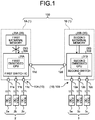
- FIG. 1 is a block diagram illustrating an example of the configuration of the vehicle communication system 100 according to the embodiment.
- FIG. 2 is a block diagram illustrating an example of the operation of the vehicle communication system 100 according to the embodiment.
- the vehicle communication system 100 is a system installed in a vehicle and configured to connect a plurality of devices 2 and 3 in the vehicle so that the devices 2 and 3 can communicate with each other.
- the vehicle communication system 100 includes a plurality of switching hubs 1 as a plurality of transfer units.
- the respective switching hubs 1 have pluralities of devices 2 and 3 and transfer information to the pluralities of devices 2 and 3.
- Each of the switching hubs 1 constitutes an on-vehicle local area network (LAN), which is a communication network provided in the vehicle.
- LAN local area network
- Ethernet registered trademark
- Each of the switching hubs 1 includes an input-output interface 10, an external memory 20, and a switch integrated circuit (IC) 30 as a transfer section.
- the switching hubs 1 include a first switching hub 1A and a second switching hub 1B.
- the first switching hub 1A includes a first input-output interface 10A, a first external memory 20A, and a first switch IC 30A as illustrated FIG. 1 .
- the first input-output interface 10A is an interface to be connected to various devices.
- the first input-output interface 10A is connected to the first switch IC 30A and is connected via communication lines to the devices 2.
- the first input-output interface 10A includes ports 11a to 11d.
- the ports 11a, 11b, and 11c are connected to devices 2a, 2b, and 2c, respectively, via communication lines.
- the port 11d is connected to the second switching hub 1B via a communication line.
- the first external memory 20A stores information therein.
- the first external memory 20A is, for example, a non-volatile memory and is made of a magnetic storage apparatus, an optical disc, or a flash memory.
- the first external memory 20A is provided outside the first switch IC 30A and is connected via a communication line to the first switch IC 30A.
- the first external memory 20A has information stored therein that is needed for putting the switch ICs 30 corresponding to the first external memory 20A and the other external memory or memories into operation.
- the first external memory 20A has setting information stored therein that is used for, for example, setting operation of the first and a second switch ICs 30A and 30B.
- the first external memory 20A may have, for example, setting information for all of the switches IC 30 included in the vehicle communication system 100.
- the setting information applicable to the first switch IC 30A contains, for example, a routing table.
- the respective MAC addresses of the devices 2 are associated with port numbers assigned in the first input-output interface 10A.
- the MAC address of the device 2a is associated with the port number of the port 11a
- the MAC address of the device 2c with the port number of the port 11c
- the second switching hub 1B with the port number of the port 11d.
- the first switch IC 30A is connected to the devices 2 to execute a process to transfer information to each of the devices 2.
- the first switch IC 30A is an electronic part obtained by forming elements such as a transistor, a resistance, and a capacitor on a circuit board.
- the first switch IC 30A includes a first embedded central processing unit (CPU) 31A.
- the first embedded CPU 31A is mounted on the circuit board for the first switch IC 30A and embedded in the first switch IC 30A.
- the first embedded CPU 31A is connected to the first external memory 20A and is connected via the first input-output interface 10A to the devices 2 and the second switching hub 1B.
- the first embedded CPU 31A operates after reading setting information applicable to the first embedded CPU 31A from the first external memory 20A. For example, when the first switching hub 1A is powered on and started up, the first embedded CPU 31A reads the setting information applicable thereto from the first external memory 20A. The first embedded CPU 31A writes the read setting information applicable thereto into an internal memory (not illustrated) in the first switch IC 30A and operates based on the setting information thus written into the internal memory.
- the first embedded CPU 31A transmits information to each of the devices 2 based on the routing table contained in the setting information applicable to the first embedded CPU 31A.
- the first embedded CPU 31A refers to the routing table, for example, when an Ethernet frame is output from the second switching hub 1B.
- the first embedded CPU 31A compares a destination MAC address contained in the Ethernet frame with the respective MAC addresses of the devices 2 that have been registered in the routing table.
- the first embedded CPU 31A detects the MAC address of the device 2 that is identical to the destination MAC address, and acquires the port number associated with the detected MAC address of the device 2.
- the first embedded CPU 31A then outputs the Ethernet frame to one of the ports 11a to 11c that is indicated by the acquired port number.
- the second switching hub 1B is configured in the same manner as the first switching hub 1A described above. Specifically, the second switching hub 1B includes a second input-output interface 10B, a second external memory 20B, and a second switch IC 30B as a transfer section.
- the second input-output interface 10B is an interface to be connected to various devices.
- the second input-output interface 10B is connected to the second switch IC 30B and is connected via communication lines to the devices 3.
- the second input-output interface 10B is configured by including ports 12a to 12d.
- the ports 12a, 12b, and 12c are connected to devices 3a, 3b, and 3c, respectively, via communication lines.
- the port 12d is connected to the first switching hub 1A via a communication line.
- the second external memory 20B stores information therein.
- the second external memory 20B is, for example, a non-volatile memory and is made of a magnetic storage apparatus, an optical disc, or a flash memory.
- the second external memory 20B is provided outside the second switch IC 30B and is connected to the second switch IC 30B via a communication line.
- the second external memory 20B has information stored therein that is needed for putting the switch ICs 30 corresponding to the second external memory 20B and the other external memory or memories into operation.
- the second external memory 20B has setting information stored therein that is used for, for example, setting operation of the first and the second switch ICs 30A and 30B.
- the second external memory 20B may have, for example, setting information applicable to all of the switches IC 30 included in the vehicle communication system 100.
- the setting information applicable to the second switch IC 30B contains, for example, a routing table.
- the respective MAC addresses of the devices 3 are associated with port numbers assigned in the second input-output interface 10B.
- the MAC address of the device 3a is associated with the port number of the port 12a
- the MAC address of the device 3c with the port number of the port 12c
- the MAC address of the first switching hub 1A with the port number of the port 12d.
- the second switch IC 30B is connected to a plurality of devices 3 to execute a process to transfer information to each of the devices 3.
- the second switch IC 30B is an electronic part obtained by forming elements such as a transistor, a resistance, and a capacitor on a circuit board.
- the second switch IC 30B includes a second embedded CPU 31B.
- the second embedded CPU 31B is mounted on the circuit board for the second switch IC 30B and embedded in the second switch IC 30B.
- the second embedded CPU 31B is connected to the second external memory 20B and is connected via the second input-output interface 10B to the devices 3 and the first switching hub 1A.
- the second embedded CPU 31B operates after reading setting information applicable to the second embedded CPU 31B from the second external memory 20B. For example, when the second switching hub 1B is powered on and started up, the second embedded CPU 31B reads the setting information applicable thereto from the second external memory 20B. The second embedded CPU 31B writes the read setting information applicable thereto into an internal memory (not illustrated) in the second switch IC 30B and operates based on the setting information thus written into the internal memory.
- the second embedded CPU 31B transmits information to each of the devices 3 based on the routing table contained in the setting information applicable to the second embedded CPU 31B.
- the second embedded CPU 31B refers to the routing table, for example, when an Ethernet frame is output from the first switching hub 1A.
- the second embedded CPU 31B compares a destination MAC address contained in the Ethernet frame with the respective MAC addresses of the devices 3 that have been registered in the routing table.
- the second embedded CPU 31B detects the MAC address of the device 3 that is identical to the destination MAC address, and acquires the port number associated with the detected MAC address of the device 3.
- the second embedded CPU 31B then outputs the Ethernet frame to one of the ports 12a to 12c that is indicated by the acquired port number.
- the first embedded CPU 31A fails to read the setting information applicable to the first embedded CPU 31A from the first external memory 20A.
- the first embedded CPU 31A operates based on setting information applicable thereto acquired from another switching hub 1, for example, the second external memory 20B in the second switching hub 1B.
- the following details a case when failure to read the setting information applicable to the first embedded CPU 31A occurs.
- the first embedded CPU 31A reads the setting information applicable to the first embedded CPU 31A from the first external memory 20A when the first switching hub 1A is started up. However, the first embedded CPU 31A fails to read the setting information applicable thereto from the first external memory 20A, for example, when the first external memory 20A is out of order. Upon occurrence of such a read error, the first embedded CPU 31A transmits, to the second switching hub 1B, a request frame F1 indicating a request for transmission of the setting information of the first embedded CPU 31A, as illustrated FIG. 2 . Upon receiving the request frame F1 from the first switching hub 1A, the second embedded CPU 31B of the second switching hub 1B reads the setting information applicable to the first switch IC 30A and stored in the second external memory 20B.
- the second embedded CPU 31B then transmits, to the first switching hub 1A, a response frame F2 containing the read setting information applicable to the first switch IC 30A.
- the first embedded CPU 31A in the first switching hub 1A operates based on the setting information applicable thereto contained in the response frame F2 transmitted from the second switching hub 1B.
- FIG. 3 is a flowchart illustrating an example of the operation of the vehicle communication system 100 according to the embodiment.
- the first switch IC 30A (the first embedded CPU 31A) reads setting information from the first external memory 20A (step S1). If the first switch IC 30A has failed to read the setting information from the first external memory 20A (Yes at step S2), the first switch IC 30A notifies a passenger of a read error using a warning lamp or the like not illustrated (step S3).
- the first switch IC 30A requests an n-th switch IC 30 to transmit setting information (step S4).
- the n-th switch IC 30 is the n-th switch IC 30.
- the first switch IC 30A transmits, to the second switch IC 30B, the request frame F1 indicating a request for transmission of the setting information.
- the n-th switch IC 30 receives the transmission request from the first switch IC 30A (step S5).
- the second switch IC 30B receives the request frame F1 transmitted from the first switch IC 30A.
- the n-th switch IC 30 reads setting information from an n-th external memory 20 (step S6).
- the second switch IC 30B reads the setting information applicable to the first switch IC 30A and stored in the second external memory 20B.
- the n-th switch IC 30 transmits the setting information to the first switch IC 30A (step S7).
- the second switch IC 30B transmits, to the first switch IC 30A, the response frame F2 containing the read setting information applicable to the first switch IC 30A.
- the first switch IC 30A receives the setting information from the n-th switch IC 30 (step S8).
- the first switch IC 30A receives the response frame F2 containing the setting information applicable to the first switch IC 30A from the second switch IC 30B. Subsequently, the first switch IC 30A reads the setting information contained in a response frame F2 received thereby (step S9). When the first switch IC 30A fails to read the setting information applicable thereto contained in the response frame F2 (Yes at step S10), the first switch IC 30A determines whether all of the other switches IC 30 have been requested to transmit the setting information (step S11).
- the first switch IC 30A requests the (n+1)-th switch IC 30 (for example, a third switch IC 30) that is the subsequent switch IC 30 to transmit the setting information (steps S12 and S4). If all of the other switches IC 30 have been requested to transmit the setting information (Yes at step S11), the first switch IC 30A switches to another communication route (step S13) and stops the first switching hub 1A from functioning (step S14). The first switch IC 30A then notifies the passenger using a warning lamp or the like that the first switching hub 1A has been stopped from functioning (step S15) and ends the process of reading the setting information.
- the first switch IC 30A requests the (n+1)-th switch IC 30 (for example, a third switch IC 30) that is the subsequent switch IC 30 to transmit the setting information (steps S12 and S4). If all of the other switches IC 30 have been requested to transmit the setting information (Yes at step S11), the first switch IC 30A switches to another communication route (step S13) and stops
- step S2 If the first switch IC 30A has not failed to read the setting information from the first external memory 20A in step S2 described above (No at step S2), the process of reading the setting information is ended. Additionally, if the first switch IC 30A has not failed to read the setting information contained in the response frame F2 (No at step S10), the process of reading the setting information is ended.
- the vehicle communication system 100 includes the switching hubs 1.
- the vehicle communication system 100 includes, for example, the first switching hub 1A and the second switching hub 1B.
- the first switching hub 1A includes: the first switch IC 30A installed in the vehicle, connected to the devices 2, and configured to transfer information to each of the devices 2; and the first external memory 20A connected to the first switch IC 30A and capable of storing information therein.
- the second switching hub 1B includes: the second switch IC 30B installed in the vehicle, connected to the devices 3, and configured to transfer information to each of the devices 3; and the second external memory 20B connected to the second switch IC 30B and capable of storing information therein.
- the first and the second switching hubs 1A and 1B are connected to each other and have setting information stored in each of the first and the second external memories 20A and 20B.
- the setting information is applicable for setting the operation of the first and the second switch ICs 30A and 30B.
- the first switching hub 1A fails to read the setting information applicable thereto and stored in the first external memory 20A in the first switching hub 1A, the first switching hub 1A operates based on the setting information applicable thereto acquired from the second external memory 20B.
- this configuration enables the first switching hub 1A to operate based on the setting information applicable thereto acquired from the second external memory 20B even in a case when the first switching hub 1A fails to acquire the setting information applicable thereto stored in the first external memory 20A therein.
- this configuration enables the first switching hub 1A to operate based on the setting information applicable thereto acquired from the second external memory 20B even in a case when the second switching hub 1B fails to acquire the setting information applicable thereto stored in the first external memory 20A therein. Consequently, the vehicle communication system 100 is provided with a fail-safe that enables normal operation even when the external memory 20 is out of order, thereby being improved in reliability.
- the fail-safe described above can be implemented by use of electronic parts conventionally used, whereby increase in the number of parts is suppressed. As a result, the vehicle communication system 100 can be light-weight.
- a vehicle communication system 100A according to a second embodiment is described.
- the same reference signs are used to indicate the same constituent elements as those in the first embodiment, and detailed description thereof is omitted.
- the vehicle communication system 100A is different from the vehicle communication system 100 according to the first embodiment in that, when errors in reading setting information occur in a plurality of certain memories, the setting information is acquired from the same one of the other external memories 20 upon occurrence of each error.
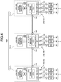
- the vehicle communication system 100A includes the first switching hub 1A, the second switching hub 1B, a third switching hub 1C as illustrated FIG. 4 .
- the second embodiment assumes that errors in reading setting information occur in the first switching hub 1A and the third switching hub 1C.
- the first switching hub 1A transmits, to the second switching hub 1B, a request frame F1 indicating a request to transmit the setting information applicable thereto.
- the second switching hub 1B Upon receiving the request frame F1 from the first switching hub 1A, the second switching hub 1B reads the setting information applicable to the first switch IC 30A and stored in the second external memory 20B. The second switching hub 1B then transmits, to the first switching hub 1A, a response frame F2 containing the read setting information applicable to the first switch IC 30A.
- the first switching hub 1A operates based on the setting information applicable thereto contained in the response frame F2 transmitted from the second switching hub 1B.
- the third switching hub 1C transmits, to the second switching hub 1B, a request frame F1 indicating a request to transmit the applicable setting information.
- the second switching hub 1B Upon receiving the request frame F1 from the third switching hub 1C, the second switching hub 1B reads the setting information applicable to a third switch IC 30C and stored in the second external memory 20B. The second switching hub 1B then transmits, to the third switching hub 1C, a response frame F2 containing the read setting information applicable to the third switch IC 30C.
- the third switching hub 1C operates based on the setting information applicable thereto contained in the response frame F2 transmitted from the second switching hub 1B.
- the switching hubs 1 include two or more acquirement-disabled switching hubs 1 that cannot acquire setting information applicable thereto and stored in the external memories 20 therein, and includes at least one acquirement-enabled transfer unit that can acquire setting information applicable thereto and stored in the external memory 20 therein.
- the two or more acquirement-disabled switching hubs 1 operate based on the setting information applicable thereto acquired from the external memory 20 in the same acquirement-enabled switching hub 1.
- this configuration enables a load imposed on the entire system to be distributed, for example, by causing one of the switching hubs 1 that has a relatively small transfer processing load imposed thereon to transmit setting information to the other switching hubs 1.
- the switching hub 1 that has a relatively small transfer processing load imposed thereon may be previously identified.
- the switching hub 1 that has a relatively small transfer processing load imposed thereon may be determined based on the result of detection of respective transfer processing loads imposed on the switching hubs 1.
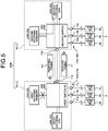
- the vehicle communication system 100B is different from the vehicle communication system 100 according to the first embodiment in that the switching hubs 1 include respective external CPUs 40.
- the first switching hub 1A includes the first input-output interface 10A, the first external memory 20A, the first switch IC 30A, and a first external CPU 40A as illustrated FIG. 5 .
- the first external CPU 40A is provided outside the first switch IC 30A and is connected via a connecting line to the first switch IC 30A.
- the first external CPU 40A has a higher processing capacity than the first embedded CPU 31A in the first switch IC 30A.
- the first external CPU 40A have a higher clock frequency with which the corresponding CPU operates than the first embedded CPU 31A, have a higher number of CPU cores than the first embedded CPU 31A, and have a larger cache memory capacity than the first embedded CPU 31A.
- the second switching hub 1B includes the second input-output interface 10B, the second external memory 20B, the second switch IC 30B, and a second external CPU 40B.
- the second external CPU 40B is provided outside the second switch IC 30B and is connected via a connecting line to the second switch IC 30B.
- the second external CPU 40B has a higher processing capacity than the second embedded CPU 31B in the second switch IC 30B.
- the second external CPU 40B have a higher clock frequency with which the corresponding CPU operates than the second embedded CPU 31B, have a higher number of CPU cores than the second embedded CPU 31B, and have a larger cache memory capacity than the second embedded CPU 31B.
- the first external CPU 40A reads setting information applicable thereto from the first external memory 20A when the first switching hub 1A is started up. If the first external CPU 40A fails to read the setting information applicable thereto from the first external memory 20A when the first switching hub 1A is started up, the first external CPU 40A transmits, to the second switching hub 1B, a request frame F1 indicating a request to transmit the setting information applicable thereto. Upon receiving the request frame F1 from the first switching hub 1A, the second external CPU 40B of the second switching hub 1B reads the setting information stored in the second external memory 20B and applicable to the first switch IC 30A.
- the second external CPU 40B then transmits, to the first switching hub 1A, a response frame F2 containing the read setting information applicable to the first switch IC 30A.
- the first external CPU 40A in the first switching hub 1A applies the applicable setting information to the first switch IC 30A contained in the response frame F2 transmitted from the second switching hub 1B.
- the applicable setting information may be acquired by the corresponding external CPU 40.
- the first and the second external memories 20A and 20B have the setting information applicable to all of the switches IC 30 included in the vehicle communication system 100 is described above.
- the first external memory 20A may be configured to store therein, out of the setting information applicable to all of the switches IC 30 included in the vehicle communication system 100, the setting information applicable to some of those switches IC 30.
- the vehicle is configured to have the internal space thereof segmented into a plurality of regions.
- the regions include a unit region that includes two or more of the switching hubs 1.
- Each of the switching hubs 1 included in this unit region stores therein the setting information applicable to that switching hub 1 and the other switching hub or hubs 1 in this unit region and does not store therein the setting information applicable to the other switching hubs 1 in the other region or regions.
- the first switching hub 1A and the second switching hub 1B are included.
- the first switching hub 1A included in this unit region stores therein the setting information applicable thereto and to the second switching hub 1B in this unit region and does not store therein the setting information applicable to the other switching hubs 1 in the other region or regions.
- This configuration can prevent capacities needed for the respective external memories 20 of the switching hubs 1 from being increased in the vehicle communication system 100.
- the transfer unit is the switching hub 1 that transfers information to a specific port based on the routing table.
- the transfer unit may be a hub that transfers information to all corresponding ports.
- a transfer unit when a transfer unit fails to acquire setting information applicable thereto from a storage section therein, the transfer unit is enabled to operate based on the setting information applicable thereto acquired from a storage section in another transfer unit, whereby the reliability of the vehicle communication system can be prevented from degrading.
Landscapes
- Engineering & Computer Science (AREA)
- Theoretical Computer Science (AREA)
- Physics & Mathematics (AREA)
- General Engineering & Computer Science (AREA)
- General Physics & Mathematics (AREA)
- Quality & Reliability (AREA)
- Human Computer Interaction (AREA)
- General Health & Medical Sciences (AREA)
- Computing Systems (AREA)
- Health & Medical Sciences (AREA)
- Medical Informatics (AREA)
- Computer Networks & Wireless Communication (AREA)
- Signal Processing (AREA)
- Mechanical Engineering (AREA)
- Small-Scale Networks (AREA)
Description
- The present invention relates to a vehicle communication system.
- Document
US 2007/073875 A1 describes a computer system and boot control method, wherein booting is performed by a storage area network and a spare (secondary) computer can take over operation of a failing computer. - Examples of a conventional vehicle communication system include a communication system that includes a switching hub for connecting between a plurality of on-vehicle devices and performs communications between the on-vehicle devices via the switching hub. The switching hub has a memory, and the memory has setting information stored therein that is used for setting the operation of the switching hub. Japanese Patent Application Laid-open No.
2016-212044 - The communication system as described above operates, for example, with the setting information read by the switching hub from the memory. At times, however, the switching hub fails to read the setting information from the memory and consequently fails to operate normally, which may degrade the reliability of the communication system.
- Given this inconvenience, the present invention has been made to provide a vehicle communication system the reliability of which can be prevented from degrading.
- This is achieved by the features of the independent claims.
- According to an aspect of the present invention, in the vehicle communication system, it is preferable that the vehicle is segmented into a plurality of regions, the regions include a unit region that is a region including two or more of the transfer units, and each of the transfer units included in the unit region stores therein the setting information applicable to that transfer unit and the other transfer unit or units in the unit region and does not store therein any of the setting information applicable to the other transfer units in the other regions.
- According to still another aspect of the present invention, in the vehicle communication system, it is preferable that when the transfer units include a plurality of acquirement-disabled transfer units that are not enabled to acquire the setting information applicable to and stored in the storage sections in these acquirement-disabled transfer sections units and include at least one acquirement-enabled transfer unit that is enabled to acquire the setting information applicable to and stored in that acquirement-enabled transfer unit, each of the plurality of acquirement-disabled transfer units operates based on the setting information applicable to that acquirement-disabled transfer unit and acquired from the storage section in the same one of the at least one acquirement-enabled transfer unit.
- The above and other objects, features, advantages and technical and industrial significance of this invention will be better understood by reading the following detailed description of presently preferred embodiments of the invention, when considered in connection with the accompanying drawings.
-
-
FIG. 1 is a block diagram illustrating an example of the configuration of a vehicle communication system according to a first embodiment; -
FIG. 2 is a block diagram illustrating an example of the operation of the vehicle communication system according to the first embodiment; -
FIG. 3 is a flowchart illustrating an example of the operation of the vehicle communication system according to the first embodiment; -
FIG. 4 is a block diagram illustrating an example of the operation of a vehicle communication system according to a second embodiment; and -
FIG. 5 is a block diagram illustrating an example of the configuration of a vehicle communication system according to a modification of a third embodiment. - With reference to the drawings, the following details modes (embodiments) for carrying out the present invention. Descriptions in the following embodiments are not intended to limit the present invention. The constituent elements described below include those that can be easily conceived by the skilled person and those that are substantially the same. Furthermore, the configurations described below can be combined as appropriate. Various omissions, substitutions, and changes can be made to the configurations without departing from the scope of the present invention.
- A
vehicle communication system 100 according to an embodiment is described with reference to the drawings.FIG. 1 is a block diagram illustrating an example of the configuration of thevehicle communication system 100 according to the embodiment.FIG. 2 is a block diagram illustrating an example of the operation of thevehicle communication system 100 according to the embodiment. Thevehicle communication system 100 is a system installed in a vehicle and configured to connect a plurality ofdevices devices vehicle communication system 100 includes a plurality ofswitching hubs 1 as a plurality of transfer units. Therespective switching hubs 1 have pluralities ofdevices devices switching hubs 1 constitutes an on-vehicle local area network (LAN), which is a communication network provided in the vehicle. For example, the communication standard for Ethernet (registered trademark) is applied to the on-vehicle LAN. This example, however, is not limiting. - Each of the
switching hubs 1 includes an input-output interface 10, anexternal memory 20, and a switch integrated circuit (IC) 30 as a transfer section. In the first embodiment, theswitching hubs 1 include afirst switching hub 1A and asecond switching hub 1B. Thefirst switching hub 1A includes a first input-output interface 10A, a firstexternal memory 20A, and a first switch IC 30A as illustratedFIG. 1 . - The first input-
output interface 10A is an interface to be connected to various devices. The first input-output interface 10A is connected to the first switch IC 30A and is connected via communication lines to thedevices 2. The first input-output interface 10A includesports 11a to 11d. Theports devices port 11d is connected to thesecond switching hub 1B via a communication line. - The first
external memory 20A stores information therein. The firstexternal memory 20A is, for example, a non-volatile memory and is made of a magnetic storage apparatus, an optical disc, or a flash memory. The firstexternal memory 20A is provided outside the first switch IC 30A and is connected via a communication line to the first switch IC 30A. The firstexternal memory 20A has information stored therein that is needed for putting theswitch ICs 30 corresponding to the firstexternal memory 20A and the other external memory or memories into operation. The firstexternal memory 20A has setting information stored therein that is used for, for example, setting operation of the first and asecond switch ICs external memory 20A may have, for example, setting information for all of theswitches IC 30 included in thevehicle communication system 100. The setting information applicable to thefirst switch IC 30A contains, for example, a routing table. In this routing table, the respective MAC addresses of thedevices 2 are associated with port numbers assigned in the first input-output interface 10A. For example, the MAC address of thedevice 2a is associated with the port number of theport 11a, the MAC address of thedevice 2b with the port number of theport 11b, the MAC address of thedevice 2c with the port number of theport 11c, and the MAC address of thesecond switching hub 1B with the port number of theport 11d. - The
first switch IC 30A is connected to thedevices 2 to execute a process to transfer information to each of thedevices 2. Thefirst switch IC 30A is an electronic part obtained by forming elements such as a transistor, a resistance, and a capacitor on a circuit board. Thefirst switch IC 30A includes a first embedded central processing unit (CPU) 31A. The first embeddedCPU 31A is mounted on the circuit board for thefirst switch IC 30A and embedded in thefirst switch IC 30A. The first embeddedCPU 31A is connected to the firstexternal memory 20A and is connected via the first input-output interface 10A to thedevices 2 and thesecond switching hub 1B. - The first embedded
CPU 31A operates after reading setting information applicable to the first embeddedCPU 31A from the firstexternal memory 20A. For example, when thefirst switching hub 1A is powered on and started up, the first embeddedCPU 31A reads the setting information applicable thereto from the firstexternal memory 20A. The first embeddedCPU 31A writes the read setting information applicable thereto into an internal memory (not illustrated) in thefirst switch IC 30A and operates based on the setting information thus written into the internal memory. - After the startup, the first embedded
CPU 31A transmits information to each of thedevices 2 based on the routing table contained in the setting information applicable to the first embeddedCPU 31A. The first embeddedCPU 31A refers to the routing table, for example, when an Ethernet frame is output from thesecond switching hub 1B. The first embeddedCPU 31A then compares a destination MAC address contained in the Ethernet frame with the respective MAC addresses of thedevices 2 that have been registered in the routing table. The first embeddedCPU 31A then detects the MAC address of thedevice 2 that is identical to the destination MAC address, and acquires the port number associated with the detected MAC address of thedevice 2. The first embeddedCPU 31A then outputs the Ethernet frame to one of theports 11a to 11c that is indicated by the acquired port number. - The
second switching hub 1B is configured in the same manner as thefirst switching hub 1A described above. Specifically, thesecond switching hub 1B includes a second input-output interface 10B, a secondexternal memory 20B, and asecond switch IC 30B as a transfer section. - The second input-
output interface 10B is an interface to be connected to various devices. The second input-output interface 10B is connected to thesecond switch IC 30B and is connected via communication lines to thedevices 3. The second input-output interface 10B is configured by includingports 12a to 12d. Theports devices port 12d is connected to thefirst switching hub 1A via a communication line. - The second
external memory 20B stores information therein. The secondexternal memory 20B is, for example, a non-volatile memory and is made of a magnetic storage apparatus, an optical disc, or a flash memory. The secondexternal memory 20B is provided outside thesecond switch IC 30B and is connected to thesecond switch IC 30B via a communication line. The secondexternal memory 20B has information stored therein that is needed for putting theswitch ICs 30 corresponding to the secondexternal memory 20B and the other external memory or memories into operation. The secondexternal memory 20B has setting information stored therein that is used for, for example, setting operation of the first and thesecond switch ICs external memory 20B may have, for example, setting information applicable to all of theswitches IC 30 included in thevehicle communication system 100. The setting information applicable to thesecond switch IC 30B contains, for example, a routing table. In this routing table, the respective MAC addresses of thedevices 3 are associated with port numbers assigned in the second input-output interface 10B. For example, the MAC address of thedevice 3a is associated with the port number of theport 12a, the MAC address of thedevice 3b with the port number of theport 12b, the MAC address of thedevice 3c with the port number of theport 12c, and the MAC address of thefirst switching hub 1A with the port number of theport 12d. - The
second switch IC 30B is connected to a plurality ofdevices 3 to execute a process to transfer information to each of thedevices 3. Thesecond switch IC 30B is an electronic part obtained by forming elements such as a transistor, a resistance, and a capacitor on a circuit board. Thesecond switch IC 30B includes a second embeddedCPU 31B. The second embeddedCPU 31B is mounted on the circuit board for thesecond switch IC 30B and embedded in thesecond switch IC 30B. The second embeddedCPU 31B is connected to the secondexternal memory 20B and is connected via the second input-output interface 10B to thedevices 3 and thefirst switching hub 1A. - The second embedded
CPU 31B operates after reading setting information applicable to the second embeddedCPU 31B from the secondexternal memory 20B. For example, when thesecond switching hub 1B is powered on and started up, the second embeddedCPU 31B reads the setting information applicable thereto from the secondexternal memory 20B. The second embeddedCPU 31B writes the read setting information applicable thereto into an internal memory (not illustrated) in thesecond switch IC 30B and operates based on the setting information thus written into the internal memory. - After the startup, the second embedded
CPU 31B transmits information to each of thedevices 3 based on the routing table contained in the setting information applicable to the second embeddedCPU 31B. The second embeddedCPU 31B refers to the routing table, for example, when an Ethernet frame is output from thefirst switching hub 1A. The second embeddedCPU 31B then compares a destination MAC address contained in the Ethernet frame with the respective MAC addresses of thedevices 3 that have been registered in the routing table. The second embeddedCPU 31B then detects the MAC address of thedevice 3 that is identical to the destination MAC address, and acquires the port number associated with the detected MAC address of thedevice 3. The second embeddedCPU 31B then outputs the Ethernet frame to one of theports 12a to 12c that is indicated by the acquired port number. - Described next is a case when the first embedded
CPU 31A fails to read the setting information applicable to the first embeddedCPU 31A from the firstexternal memory 20A. When failing to read the setting information applicable thereto from the firstexternal memory 20A, the first embeddedCPU 31A operates based on setting information applicable thereto acquired from another switchinghub 1, for example, the secondexternal memory 20B in thesecond switching hub 1B. The following details a case when failure to read the setting information applicable to the first embeddedCPU 31A occurs. - The first embedded
CPU 31A reads the setting information applicable to the first embeddedCPU 31A from the firstexternal memory 20A when thefirst switching hub 1A is started up. However, the first embeddedCPU 31A fails to read the setting information applicable thereto from the firstexternal memory 20A, for example, when the firstexternal memory 20A is out of order. Upon occurrence of such a read error, the first embeddedCPU 31A transmits, to thesecond switching hub 1B, a request frame F1 indicating a request for transmission of the setting information of the first embeddedCPU 31A, as illustratedFIG. 2 . Upon receiving the request frame F1 from thefirst switching hub 1A, the second embeddedCPU 31B of thesecond switching hub 1B reads the setting information applicable to thefirst switch IC 30A and stored in the secondexternal memory 20B. The second embeddedCPU 31B then transmits, to thefirst switching hub 1A, a response frame F2 containing the read setting information applicable to thefirst switch IC 30A. The first embeddedCPU 31A in thefirst switching hub 1A operates based on the setting information applicable thereto contained in the response frame F2 transmitted from thesecond switching hub 1B. - Next described is an example of the operation of the
vehicle communication system 100 according to the embodiment.FIG. 3 is a flowchart illustrating an example of the operation of thevehicle communication system 100 according to the embodiment. Thefirst switch IC 30A (the first embeddedCPU 31A) reads setting information from the firstexternal memory 20A (step S1). If thefirst switch IC 30A has failed to read the setting information from the firstexternal memory 20A (Yes at step S2), thefirst switch IC 30A notifies a passenger of a read error using a warning lamp or the like not illustrated (step S3). - Subsequently, the
first switch IC 30A requests an n-th switch IC 30 to transmit setting information (step S4). The n-th switch IC 30 is the n-th switch IC 30. In this example, thefirst switch IC 30A transmits, to thesecond switch IC 30B, the request frame F1 indicating a request for transmission of the setting information. Subsequently, the n-th switch IC 30 receives the transmission request from thefirst switch IC 30A (step S5). In this example, thesecond switch IC 30B receives the request frame F1 transmitted from thefirst switch IC 30A. - Subsequently, the n-
th switch IC 30 reads setting information from an n-th external memory 20 (step S6). In this example, thesecond switch IC 30B reads the setting information applicable to thefirst switch IC 30A and stored in the secondexternal memory 20B. Subsequently, the n-th switch IC 30 transmits the setting information to thefirst switch IC 30A (step S7). In this example, thesecond switch IC 30B transmits, to thefirst switch IC 30A, the response frame F2 containing the read setting information applicable to thefirst switch IC 30A. Subsequently, thefirst switch IC 30A receives the setting information from the n-th switch IC 30 (step S8). In this example, thefirst switch IC 30A receives the response frame F2 containing the setting information applicable to thefirst switch IC 30A from thesecond switch IC 30B. Subsequently, thefirst switch IC 30A reads the setting information contained in a response frame F2 received thereby (step S9). When thefirst switch IC 30A fails to read the setting information applicable thereto contained in the response frame F2 (Yes at step S10), thefirst switch IC 30A determines whether all of theother switches IC 30 have been requested to transmit the setting information (step S11). - If any of the
other switches IC 30 has not been requested to transmit the setting information (No at step S11), thefirst switch IC 30A requests the (n+1)-th switch IC 30 (for example, a third switch IC 30) that is thesubsequent switch IC 30 to transmit the setting information (steps S12 and S4). If all of theother switches IC 30 have been requested to transmit the setting information (Yes at step S11), thefirst switch IC 30A switches to another communication route (step S13) and stops thefirst switching hub 1A from functioning (step S14). Thefirst switch IC 30A then notifies the passenger using a warning lamp or the like that thefirst switching hub 1A has been stopped from functioning (step S15) and ends the process of reading the setting information. - If the
first switch IC 30A has not failed to read the setting information from the firstexternal memory 20A in step S2 described above (No at step S2), the process of reading the setting information is ended. Additionally, if thefirst switch IC 30A has not failed to read the setting information contained in the response frame F2 (No at step S10), the process of reading the setting information is ended. - As described above, the
vehicle communication system 100 according to the embodiment includes theswitching hubs 1. Thevehicle communication system 100 includes, for example, thefirst switching hub 1A and thesecond switching hub 1B. Thefirst switching hub 1A includes: thefirst switch IC 30A installed in the vehicle, connected to thedevices 2, and configured to transfer information to each of thedevices 2; and the firstexternal memory 20A connected to thefirst switch IC 30A and capable of storing information therein. Thesecond switching hub 1B includes: thesecond switch IC 30B installed in the vehicle, connected to thedevices 3, and configured to transfer information to each of thedevices 3; and the secondexternal memory 20B connected to thesecond switch IC 30B and capable of storing information therein. The first and thesecond switching hubs external memories second switch ICs first switching hub 1A fails to read the setting information applicable thereto and stored in the firstexternal memory 20A in thefirst switching hub 1A, thefirst switching hub 1A operates based on the setting information applicable thereto acquired from the secondexternal memory 20B. - In the
vehicle communication system 100, this configuration enables thefirst switching hub 1A to operate based on the setting information applicable thereto acquired from the secondexternal memory 20B even in a case when thefirst switching hub 1A fails to acquire the setting information applicable thereto stored in the firstexternal memory 20A therein. In thevehicle communication system 100, this configuration enables thefirst switching hub 1A to operate based on the setting information applicable thereto acquired from the secondexternal memory 20B even in a case when thesecond switching hub 1B fails to acquire the setting information applicable thereto stored in the firstexternal memory 20A therein. Consequently, thevehicle communication system 100 is provided with a fail-safe that enables normal operation even when theexternal memory 20 is out of order, thereby being improved in reliability. In thevehicle communication system 100, the fail-safe described above can be implemented by use of electronic parts conventionally used, whereby increase in the number of parts is suppressed. As a result, thevehicle communication system 100 can be light-weight. - Next, a
vehicle communication system 100A according to a second embodiment is described. In the second embodiment, the same reference signs are used to indicate the same constituent elements as those in the first embodiment, and detailed description thereof is omitted. Thevehicle communication system 100A is different from thevehicle communication system 100 according to the first embodiment in that, when errors in reading setting information occur in a plurality of certain memories, the setting information is acquired from the same one of the otherexternal memories 20 upon occurrence of each error. - The
vehicle communication system 100A includes thefirst switching hub 1A, thesecond switching hub 1B, athird switching hub 1C as illustratedFIG. 4 . The second embodiment assumes that errors in reading setting information occur in thefirst switching hub 1A and thethird switching hub 1C. - When an error in reading setting information applicable to the
first switching hub 1A occurs therein, thefirst switching hub 1A transmits, to thesecond switching hub 1B, a request frame F1 indicating a request to transmit the setting information applicable thereto. Upon receiving the request frame F1 from thefirst switching hub 1A, thesecond switching hub 1B reads the setting information applicable to thefirst switch IC 30A and stored in the secondexternal memory 20B. Thesecond switching hub 1B then transmits, to thefirst switching hub 1A, a response frame F2 containing the read setting information applicable to thefirst switch IC 30A. Thefirst switching hub 1A operates based on the setting information applicable thereto contained in the response frame F2 transmitted from thesecond switching hub 1B. - When an error in reading setting information applicable to the
third switching hub 1C occurs therein, thethird switching hub 1C transmits, to thesecond switching hub 1B, a request frame F1 indicating a request to transmit the applicable setting information. Upon receiving the request frame F1 from thethird switching hub 1C, thesecond switching hub 1B reads the setting information applicable to athird switch IC 30C and stored in the secondexternal memory 20B. Thesecond switching hub 1B then transmits, to thethird switching hub 1C, a response frame F2 containing the read setting information applicable to thethird switch IC 30C. Thethird switching hub 1C operates based on the setting information applicable thereto contained in the response frame F2 transmitted from thesecond switching hub 1B. - Thus, in the
vehicle communication system 100A, theswitching hubs 1 include two or more acquirement-disabled switching hubs 1 that cannot acquire setting information applicable thereto and stored in theexternal memories 20 therein, and includes at least one acquirement-enabled transfer unit that can acquire setting information applicable thereto and stored in theexternal memory 20 therein. In this case, in theswitching hubs 1, the two or more acquirement-disabled switching hubs 1 operate based on the setting information applicable thereto acquired from theexternal memory 20 in the same acquirement-enabledswitching hub 1. In thevehicle communication system 100A, this configuration enables a load imposed on the entire system to be distributed, for example, by causing one of theswitching hubs 1 that has a relatively small transfer processing load imposed thereon to transmit setting information to theother switching hubs 1. In thevehicle communication system 100A, the switchinghub 1 that has a relatively small transfer processing load imposed thereon may be previously identified. Alternatively, the switchinghub 1 that has a relatively small transfer processing load imposed thereon may be determined based on the result of detection of respective transfer processing loads imposed on theswitching hubs 1. - Next, a
vehicle communication system 100B according to a third embodiment is described. In the third embodiment, the same reference signs are used to indicate the same constituent elements as those in the first embodiment, and detailed description thereof is omitted. Thevehicle communication system 100B is different from thevehicle communication system 100 according to the first embodiment in that theswitching hubs 1 include respectiveexternal CPUs 40. Thefirst switching hub 1A includes the first input-output interface 10A, the firstexternal memory 20A, thefirst switch IC 30A, and a firstexternal CPU 40A as illustratedFIG. 5 . The firstexternal CPU 40A is provided outside thefirst switch IC 30A and is connected via a connecting line to thefirst switch IC 30A. The firstexternal CPU 40A has a higher processing capacity than the first embeddedCPU 31A in thefirst switch IC 30A. For example, it is preferable that the firstexternal CPU 40A have a higher clock frequency with which the corresponding CPU operates than the first embeddedCPU 31A, have a higher number of CPU cores than the first embeddedCPU 31A, and have a larger cache memory capacity than the first embeddedCPU 31A. - The
second switching hub 1B includes the second input-output interface 10B, the secondexternal memory 20B, thesecond switch IC 30B, and a secondexternal CPU 40B. The secondexternal CPU 40B is provided outside thesecond switch IC 30B and is connected via a connecting line to thesecond switch IC 30B. The secondexternal CPU 40B has a higher processing capacity than the second embeddedCPU 31B in thesecond switch IC 30B. For example, it is preferable that the secondexternal CPU 40B have a higher clock frequency with which the corresponding CPU operates than the second embeddedCPU 31B, have a higher number of CPU cores than the second embeddedCPU 31B, and have a larger cache memory capacity than the second embeddedCPU 31B. - In the first and the
second switching hubs external CPU 40A reads setting information applicable thereto from the firstexternal memory 20A when thefirst switching hub 1A is started up. If the firstexternal CPU 40A fails to read the setting information applicable thereto from the firstexternal memory 20A when thefirst switching hub 1A is started up, the firstexternal CPU 40A transmits, to thesecond switching hub 1B, a request frame F1 indicating a request to transmit the setting information applicable thereto. Upon receiving the request frame F1 from thefirst switching hub 1A, the secondexternal CPU 40B of thesecond switching hub 1B reads the setting information stored in the secondexternal memory 20B and applicable to thefirst switch IC 30A. The secondexternal CPU 40B then transmits, to thefirst switching hub 1A, a response frame F2 containing the read setting information applicable to thefirst switch IC 30A. The firstexternal CPU 40A in thefirst switching hub 1A applies the applicable setting information to thefirst switch IC 30A contained in the response frame F2 transmitted from thesecond switching hub 1B. As in the case of thevehicle communication system 100B according to the third embodiment, the applicable setting information may be acquired by the correspondingexternal CPU 40. - Modifications of the embodiments are described next. An example in which the first and the second
external memories switches IC 30 included in thevehicle communication system 100 is described above. However, this example is not limiting. For example, the firstexternal memory 20A may be configured to store therein, out of the setting information applicable to all of theswitches IC 30 included in thevehicle communication system 100, the setting information applicable to some of thoseswitches IC 30. In that case, for example, the vehicle is configured to have the internal space thereof segmented into a plurality of regions. The regions include a unit region that includes two or more of theswitching hubs 1. Each of theswitching hubs 1 included in this unit region stores therein the setting information applicable to thatswitching hub 1 and the other switching hub orhubs 1 in this unit region and does not store therein the setting information applicable to theother switching hubs 1 in the other region or regions. In one of the unit regions, for example, thefirst switching hub 1A and thesecond switching hub 1B are included. Thefirst switching hub 1A included in this unit region stores therein the setting information applicable thereto and to thesecond switching hub 1B in this unit region and does not store therein the setting information applicable to theother switching hubs 1 in the other region or regions. This configuration can prevent capacities needed for the respectiveexternal memories 20 of theswitching hubs 1 from being increased in thevehicle communication system 100. - The present description illustrates an example in which the transfer unit is the switching
hub 1 that transfers information to a specific port based on the routing table. However, this example is not limiting. For example, the transfer unit may be a hub that transfers information to all corresponding ports. - In a vehicle communication system according to the embodiments, when a transfer unit fails to acquire setting information applicable thereto from a storage section therein, the transfer unit is enabled to operate based on the setting information applicable thereto acquired from a storage section in another transfer unit, whereby the reliability of the vehicle communication system can be prevented from degrading.
- Although the invention has been described with respect to specific embodiments for a complete and clear disclosure, the appended claims are not to be thus limited but are to be construed as embodying all modifications and alternative constructions that may occur to one skilled in the art that fairly fall within the basic teaching herein set forth.
Claims (3)
- A vehicle communication system (100, 100A, 100B) comprising:a plurality of transfer units (1) each includinga transfer section (30) installed in a vehicle, connected to a device (2 and 3), and configured to transfer information to the device (2 and 3), anda storage section (20) connected to the transfer section (30) and capable of storing information therein, whereinthe transfer units (1) are connected to one another, each of the transfer units (1) stores, in the storage section (20) of that transfer unit (1), setting information needed for putting the transfer sections (30) in that transfer unit (1) and at least one of the other transfer units (1) into operation, the setting information needed for putting the transfer sections (30) in that transfer unit (1) into operation being read from said storage section (20) during startup of the respective transfer unit (1), and that transfer unit (1) operates based on the setting information applicable to that transfer unit (1) that has been acquired from the storage section (20) in the other transfer units (1) when failing to acquire the applicable setting information stored in the storage section (20) in that transfer unit (1).
- The vehicle communication system (100, 100A, 100B) according to claim 1, wherein
the vehicle is segmented into a plurality of regions,
the regions include a unit region that is a region including two or more of the transfer units (1), and
each of the transfer units (1) included in the unit region stores therein the setting information applicable to that transfer unit (1) and the other transfer unit or units (1) in the unit region and does not store therein any of the setting information applicable to the other transfer units (1) in the other regions. - The vehicle communication system (100A) according to claim 1 or 2, wherein when the transfer units (1) include a plurality of acquirement-disabled transfer units (1) that are not enabled to acquire the setting information applicable to and stored in the storage sections (20) in these acquirement-disabled transfer units (1) and include at least one acquirement-enabled transfer unit (1) that is enabled to acquire the setting information applicable to and stored in that acquirement-enabled transfer unit (1), each of the plurality of acquirement-disabled transfer units (1) operates based on the setting information applicable to that acquirement-disabled transfer unit (1) and acquired from the storage section (20) in the same one of the at least one acquirement-enabled transfer unit (1).
Applications Claiming Priority (1)
| Application Number | Priority Date | Filing Date | Title |
|---|---|---|---|
| JP2019048614A JP7058928B2 (en) | 2019-03-15 | 2019-03-15 | Vehicle communication system |
Publications (2)
| Publication Number | Publication Date |
|---|---|
| EP3719650A1 EP3719650A1 (en) | 2020-10-07 |
| EP3719650B1 true EP3719650B1 (en) | 2021-05-12 |
Family
ID=69581940
Family Applications (1)
| Application Number | Title | Priority Date | Filing Date |
|---|---|---|---|
| EP20156989.4A Active EP3719650B1 (en) | 2019-03-15 | 2020-02-12 | Vehicle communication system |
Country Status (4)
| Country | Link |
|---|---|
| US (1) | US20200293218A1 (en) |
| EP (1) | EP3719650B1 (en) |
| JP (1) | JP7058928B2 (en) |
| CN (1) | CN111698277B (en) |
Families Citing this family (1)
| Publication number | Priority date | Publication date | Assignee | Title |
|---|---|---|---|---|
| US12069829B2 (en) * | 2021-11-22 | 2024-08-20 | Mellanox Technologies, Ltd. | Dual connect switch module |
Family Cites Families (19)
| Publication number | Priority date | Publication date | Assignee | Title |
|---|---|---|---|---|
| JP2730534B2 (en) * | 1995-12-18 | 1998-03-25 | 日本電気株式会社 | Data backup method and apparatus for data communication network terminal |
| US6986008B2 (en) * | 2003-01-14 | 2006-01-10 | International Business Machines Corporation | Backup firmware in a distributed system |
| US7467035B2 (en) * | 2004-05-18 | 2008-12-16 | Haldex Brake Products Ltd. | Vehicle control system with redundant storage of vehicle control parameters |
| JP2006128901A (en) * | 2004-10-27 | 2006-05-18 | Toshiba Mitsubishi-Electric Industrial System Corp | Setting system for transmission device |
| JP4710518B2 (en) * | 2005-09-28 | 2011-06-29 | 株式会社日立製作所 | Computer system and boot control method thereof |
| WO2009090978A1 (en) * | 2008-01-15 | 2009-07-23 | Toyota Jidosha Kabushiki Kaisha | Vehicle control device |
| US8219279B2 (en) * | 2008-07-01 | 2012-07-10 | International Engine Intellectual Property Company, Llc | Method for on-board data backup for configurable programmable parameters |
| US8880776B2 (en) * | 2008-12-16 | 2014-11-04 | Sandisk Il Ltd. | Data access at a storage device using cluster information |
| WO2012014400A1 (en) * | 2010-07-27 | 2012-02-02 | パナソニック株式会社 | Data transfer control device and data transfer control method |
| US9021321B2 (en) * | 2012-12-10 | 2015-04-28 | International Business Machines Corporation | Testing disk drives shared by multiple processors in a supercomputer complex |
| US9824132B2 (en) * | 2013-01-08 | 2017-11-21 | Facebook, Inc. | Data recovery in multi-leader distributed systems |
| JP2015050504A (en) * | 2013-08-30 | 2015-03-16 | 株式会社バッファロー | Radio communication system, radio communication device, computer program therefor, and method for transmitting setting information for radio communication |
| JP6126980B2 (en) * | 2013-12-12 | 2017-05-10 | 日立オートモティブシステムズ株式会社 | Network device and network system |
| JP6266484B2 (en) * | 2014-09-26 | 2018-01-24 | アラクサラネットワークス株式会社 | COMMUNICATION DEVICE AND COMMUNICATION DEVICE CONTROL METHOD |
| JP2016092667A (en) * | 2014-11-07 | 2016-05-23 | 株式会社明電舎 | Network management method |
| JP6527386B2 (en) | 2015-05-13 | 2019-06-05 | 大成建設株式会社 | Pointer value reader and pointer value reading program |
| JP2019515531A (en) * | 2016-03-31 | 2019-06-06 | 華為技術有限公司Huawei Technologies Co.,Ltd. | Method and system for transmitting information about transmission mode, network device, and terminal device |
| US10096176B1 (en) * | 2017-05-08 | 2018-10-09 | GM Global Technology Operations LLC | System and method for vehicle-reservation reliability prognosis |
| KR102513941B1 (en) * | 2018-06-19 | 2023-03-27 | 현대자동차주식회사 | Automatic Driving control apparatus, vehicle having the same and method for controlling the same |
-
2019
- 2019-03-15 JP JP2019048614A patent/JP7058928B2/en active Active
-
2020
- 2020-02-12 EP EP20156989.4A patent/EP3719650B1/en active Active
- 2020-02-12 US US16/788,881 patent/US20200293218A1/en not_active Abandoned
- 2020-02-18 CN CN202010098680.0A patent/CN111698277B/en active Active
Also Published As
| Publication number | Publication date |
|---|---|
| EP3719650A1 (en) | 2020-10-07 |
| CN111698277B (en) | 2023-02-17 |
| US20200293218A1 (en) | 2020-09-17 |
| JP7058928B2 (en) | 2022-04-25 |
| CN111698277A (en) | 2020-09-22 |
| JP2020150494A (en) | 2020-09-17 |
Similar Documents
| Publication | Publication Date | Title |
|---|---|---|
| JP3669653B2 (en) | Computer system | |
| US5721870A (en) | Lock control for a shared main storage data processing system | |
| US11775463B2 (en) | System-on-chip and an interconnect bus included in the system on chip | |
| US20230236742A1 (en) | NONVOLATILE MEMORY EXPRESS (NVMe) OVER COMPUTE EXPRESS LINK (CXL) | |
| US11409538B2 (en) | Data processing system and method for configuring and operating a data processing system | |
| EP2294581B1 (en) | A system for distributing available memory resource | |
| CN109117399B (en) | Apparatus, system and method for reducing chip selection | |
| US7852235B1 (en) | High integrity computing via input synchronization systems and methods | |
| EP3719650B1 (en) | Vehicle communication system | |
| JP4912731B2 (en) | Redundant I/O interface management | |
| EP3279796B1 (en) | Resource access management component and method therefor | |
| CN114253475A (en) | RDMA memory application protection method, system, equipment and storage medium | |
| EP1589427A1 (en) | Boot control system | |
| US20030200401A1 (en) | Microcomputer system automatically backing-up data written in storage medium in transceiver, and transceiver connected thereto | |
| JPH10262272A (en) | Simple interface for time division multiplex communication medium | |
| EP3709167B1 (en) | Vehicle communication system | |
| JPH11232213A (en) | Data transfer system for input/output device | |
| EP3907614A1 (en) | Semiconductor device | |
| US20060129714A1 (en) | Method and apparatus for transferring data | |
| US12112176B1 (en) | Selective firmware placement during initialization of compute systems | |
| KR20120013538A (en) | Semiconductor memory device and operation method thereof | |
| US20210342278A1 (en) | Memory card for data transfer system, data storage device, system host, and memory card identification method | |
| JP2003203017A (en) | Data processing device that can continue processing with backup data | |
| JP2826483B2 (en) | Lock control device | |
| WO2025048890A1 (en) | RESERVATION OF PCIe SLOTS FOR MANAGEMENT BY A RAID DRIVER |
Legal Events
| Date | Code | Title | Description |
|---|---|---|---|
| PUAI | Public reference made under article 153(3) epc to a published international application that has entered the european phase |
Free format text: ORIGINAL CODE: 0009012 |
|
| STAA | Information on the status of an ep patent application or granted ep patent |
Free format text: STATUS: REQUEST FOR EXAMINATION WAS MADE |
|
| 17P | Request for examination filed |
Effective date: 20200212 |
|
| AK | Designated contracting states |
Kind code of ref document: A1 Designated state(s): AL AT BE BG CH CY CZ DE DK EE ES FI FR GB GR HR HU IE IS IT LI LT LU LV MC MK MT NL NO PL PT RO RS SE SI SK SM TR |
|
| AX | Request for extension of the european patent |
Extension state: BA ME |
|
| RBV | Designated contracting states (corrected) |
Designated state(s): AL AT BE BG CH CY CZ DE DK EE ES FI FR GB GR HR HU IE IS IT LI LT LU LV MC MK MT NL NO PL PT RO RS SE SI SK SM TR |
|
| GRAP | Despatch of communication of intention to grant a patent |
Free format text: ORIGINAL CODE: EPIDOSNIGR1 |
|
| STAA | Information on the status of an ep patent application or granted ep patent |
Free format text: STATUS: GRANT OF PATENT IS INTENDED |
|
| INTG | Intention to grant announced |
Effective date: 20210223 |
|
| GRAS | Grant fee paid |
Free format text: ORIGINAL CODE: EPIDOSNIGR3 |
|
| GRAA | (expected) grant |
Free format text: ORIGINAL CODE: 0009210 |
|
| STAA | Information on the status of an ep patent application or granted ep patent |
Free format text: STATUS: THE PATENT HAS BEEN GRANTED |
|
| AK | Designated contracting states |
Kind code of ref document: B1 Designated state(s): AL AT BE BG CH CY CZ DE DK EE ES FI FR GB GR HR HU IE IS IT LI LT LU LV MC MK MT NL NO PL PT RO RS SE SI SK SM TR |
|
| REG | Reference to a national code |
Ref country code: GB Ref legal event code: FG4D |
|
| REG | Reference to a national code |
Ref country code: CH Ref legal event code: EP |
|
| REG | Reference to a national code |
Ref country code: DE Ref legal event code: R096 Ref document number: 602020000092 Country of ref document: DE |
|
| REG | Reference to a national code |
Ref country code: IE Ref legal event code: FG4D |
|
| REG | Reference to a national code |
Ref country code: AT Ref legal event code: REF Ref document number: 1392637 Country of ref document: AT Kind code of ref document: T Effective date: 20210615 |
|
| REG | Reference to a national code |
Ref country code: LT Ref legal event code: MG9D |
|
| REG | Reference to a national code |
Ref country code: AT Ref legal event code: MK05 Ref document number: 1392637 Country of ref document: AT Kind code of ref document: T Effective date: 20210512 |
|
| REG | Reference to a national code |
Ref country code: NL Ref legal event code: MP Effective date: 20210512 |
|
| PG25 | Lapsed in a contracting state [announced via postgrant information from national office to epo] |
Ref country code: BG Free format text: LAPSE BECAUSE OF FAILURE TO SUBMIT A TRANSLATION OF THE DESCRIPTION OR TO PAY THE FEE WITHIN THE PRESCRIBED TIME-LIMIT Effective date: 20210812 Ref country code: AT Free format text: LAPSE BECAUSE OF FAILURE TO SUBMIT A TRANSLATION OF THE DESCRIPTION OR TO PAY THE FEE WITHIN THE PRESCRIBED TIME-LIMIT Effective date: 20210512 Ref country code: LT Free format text: LAPSE BECAUSE OF FAILURE TO SUBMIT A TRANSLATION OF THE DESCRIPTION OR TO PAY THE FEE WITHIN THE PRESCRIBED TIME-LIMIT Effective date: 20210512 Ref country code: HR Free format text: LAPSE BECAUSE OF FAILURE TO SUBMIT A TRANSLATION OF THE DESCRIPTION OR TO PAY THE FEE WITHIN THE PRESCRIBED TIME-LIMIT Effective date: 20210512 Ref country code: FI Free format text: LAPSE BECAUSE OF FAILURE TO SUBMIT A TRANSLATION OF THE DESCRIPTION OR TO PAY THE FEE WITHIN THE PRESCRIBED TIME-LIMIT Effective date: 20210512 |
|
| PG25 | Lapsed in a contracting state [announced via postgrant information from national office to epo] |
Ref country code: SE Free format text: LAPSE BECAUSE OF FAILURE TO SUBMIT A TRANSLATION OF THE DESCRIPTION OR TO PAY THE FEE WITHIN THE PRESCRIBED TIME-LIMIT Effective date: 20210512 Ref country code: PT Free format text: LAPSE BECAUSE OF FAILURE TO SUBMIT A TRANSLATION OF THE DESCRIPTION OR TO PAY THE FEE WITHIN THE PRESCRIBED TIME-LIMIT Effective date: 20210913 Ref country code: RS Free format text: LAPSE BECAUSE OF FAILURE TO SUBMIT A TRANSLATION OF THE DESCRIPTION OR TO PAY THE FEE WITHIN THE PRESCRIBED TIME-LIMIT Effective date: 20210512 Ref country code: PL Free format text: LAPSE BECAUSE OF FAILURE TO SUBMIT A TRANSLATION OF THE DESCRIPTION OR TO PAY THE FEE WITHIN THE PRESCRIBED TIME-LIMIT Effective date: 20210512 Ref country code: NO Free format text: LAPSE BECAUSE OF FAILURE TO SUBMIT A TRANSLATION OF THE DESCRIPTION OR TO PAY THE FEE WITHIN THE PRESCRIBED TIME-LIMIT Effective date: 20210812 Ref country code: LV Free format text: LAPSE BECAUSE OF FAILURE TO SUBMIT A TRANSLATION OF THE DESCRIPTION OR TO PAY THE FEE WITHIN THE PRESCRIBED TIME-LIMIT Effective date: 20210512 Ref country code: IS Free format text: LAPSE BECAUSE OF FAILURE TO SUBMIT A TRANSLATION OF THE DESCRIPTION OR TO PAY THE FEE WITHIN THE PRESCRIBED TIME-LIMIT Effective date: 20210912 Ref country code: GR Free format text: LAPSE BECAUSE OF FAILURE TO SUBMIT A TRANSLATION OF THE DESCRIPTION OR TO PAY THE FEE WITHIN THE PRESCRIBED TIME-LIMIT Effective date: 20210813 |
|
| PG25 | Lapsed in a contracting state [announced via postgrant information from national office to epo] |
Ref country code: NL Free format text: LAPSE BECAUSE OF FAILURE TO SUBMIT A TRANSLATION OF THE DESCRIPTION OR TO PAY THE FEE WITHIN THE PRESCRIBED TIME-LIMIT Effective date: 20210512 |
|
| PG25 | Lapsed in a contracting state [announced via postgrant information from national office to epo] |
Ref country code: SM Free format text: LAPSE BECAUSE OF FAILURE TO SUBMIT A TRANSLATION OF THE DESCRIPTION OR TO PAY THE FEE WITHIN THE PRESCRIBED TIME-LIMIT Effective date: 20210512 Ref country code: RO Free format text: LAPSE BECAUSE OF FAILURE TO SUBMIT A TRANSLATION OF THE DESCRIPTION OR TO PAY THE FEE WITHIN THE PRESCRIBED TIME-LIMIT Effective date: 20210512 Ref country code: DK Free format text: LAPSE BECAUSE OF FAILURE TO SUBMIT A TRANSLATION OF THE DESCRIPTION OR TO PAY THE FEE WITHIN THE PRESCRIBED TIME-LIMIT Effective date: 20210512 Ref country code: CZ Free format text: LAPSE BECAUSE OF FAILURE TO SUBMIT A TRANSLATION OF THE DESCRIPTION OR TO PAY THE FEE WITHIN THE PRESCRIBED TIME-LIMIT Effective date: 20210512 Ref country code: SK Free format text: LAPSE BECAUSE OF FAILURE TO SUBMIT A TRANSLATION OF THE DESCRIPTION OR TO PAY THE FEE WITHIN THE PRESCRIBED TIME-LIMIT Effective date: 20210512 Ref country code: EE Free format text: LAPSE BECAUSE OF FAILURE TO SUBMIT A TRANSLATION OF THE DESCRIPTION OR TO PAY THE FEE WITHIN THE PRESCRIBED TIME-LIMIT Effective date: 20210512 Ref country code: ES Free format text: LAPSE BECAUSE OF FAILURE TO SUBMIT A TRANSLATION OF THE DESCRIPTION OR TO PAY THE FEE WITHIN THE PRESCRIBED TIME-LIMIT Effective date: 20210512 |
|
| REG | Reference to a national code |
Ref country code: DE Ref legal event code: R097 Ref document number: 602020000092 Country of ref document: DE |
|
| PLBE | No opposition filed within time limit |
Free format text: ORIGINAL CODE: 0009261 |
|
| STAA | Information on the status of an ep patent application or granted ep patent |
Free format text: STATUS: NO OPPOSITION FILED WITHIN TIME LIMIT |
|
| 26N | No opposition filed |
Effective date: 20220215 |
|
| PG25 | Lapsed in a contracting state [announced via postgrant information from national office to epo] |
Ref country code: IS Free format text: LAPSE BECAUSE OF FAILURE TO SUBMIT A TRANSLATION OF THE DESCRIPTION OR TO PAY THE FEE WITHIN THE PRESCRIBED TIME-LIMIT Effective date: 20210912 Ref country code: AL Free format text: LAPSE BECAUSE OF FAILURE TO SUBMIT A TRANSLATION OF THE DESCRIPTION OR TO PAY THE FEE WITHIN THE PRESCRIBED TIME-LIMIT Effective date: 20210512 |
|
| PG25 | Lapsed in a contracting state [announced via postgrant information from national office to epo] |
Ref country code: IT Free format text: LAPSE BECAUSE OF FAILURE TO SUBMIT A TRANSLATION OF THE DESCRIPTION OR TO PAY THE FEE WITHIN THE PRESCRIBED TIME-LIMIT Effective date: 20210512 |
|
| PG25 | Lapsed in a contracting state [announced via postgrant information from national office to epo] |
Ref country code: MC Free format text: LAPSE BECAUSE OF FAILURE TO SUBMIT A TRANSLATION OF THE DESCRIPTION OR TO PAY THE FEE WITHIN THE PRESCRIBED TIME-LIMIT Effective date: 20210512 |
|
| REG | Reference to a national code |
Ref country code: BE Ref legal event code: MM Effective date: 20220228 |
|
| PG25 | Lapsed in a contracting state [announced via postgrant information from national office to epo] |
Ref country code: LU Free format text: LAPSE BECAUSE OF NON-PAYMENT OF DUE FEES Effective date: 20220212 |
|
| PG25 | Lapsed in a contracting state [announced via postgrant information from national office to epo] |
Ref country code: FR Free format text: LAPSE BECAUSE OF NON-PAYMENT OF DUE FEES Effective date: 20220228 |
|
| PG25 | Lapsed in a contracting state [announced via postgrant information from national office to epo] |
Ref country code: IE Free format text: LAPSE BECAUSE OF NON-PAYMENT OF DUE FEES Effective date: 20220212 |
|
| PG25 | Lapsed in a contracting state [announced via postgrant information from national office to epo] |
Ref country code: BE Free format text: LAPSE BECAUSE OF NON-PAYMENT OF DUE FEES Effective date: 20220228 |
|
| REG | Reference to a national code |
Ref country code: CH Ref legal event code: PL |
|
| PG25 | Lapsed in a contracting state [announced via postgrant information from national office to epo] |
Ref country code: LI Free format text: LAPSE BECAUSE OF NON-PAYMENT OF DUE FEES Effective date: 20230228 Ref country code: CH Free format text: LAPSE BECAUSE OF NON-PAYMENT OF DUE FEES Effective date: 20230228 |
|
| PG25 | Lapsed in a contracting state [announced via postgrant information from national office to epo] |
Ref country code: MK Free format text: LAPSE BECAUSE OF FAILURE TO SUBMIT A TRANSLATION OF THE DESCRIPTION OR TO PAY THE FEE WITHIN THE PRESCRIBED TIME-LIMIT Effective date: 20210512 Ref country code: CY Free format text: LAPSE BECAUSE OF FAILURE TO SUBMIT A TRANSLATION OF THE DESCRIPTION OR TO PAY THE FEE WITHIN THE PRESCRIBED TIME-LIMIT Effective date: 20210512 |
|
| PG25 | Lapsed in a contracting state [announced via postgrant information from national office to epo] |
Ref country code: HU Free format text: LAPSE BECAUSE OF FAILURE TO SUBMIT A TRANSLATION OF THE DESCRIPTION OR TO PAY THE FEE WITHIN THE PRESCRIBED TIME-LIMIT; INVALID AB INITIO Effective date: 20200212 |
|
| PG25 | Lapsed in a contracting state [announced via postgrant information from national office to epo] |
Ref country code: TR Free format text: LAPSE BECAUSE OF FAILURE TO SUBMIT A TRANSLATION OF THE DESCRIPTION OR TO PAY THE FEE WITHIN THE PRESCRIBED TIME-LIMIT Effective date: 20210512 |
|
| PG25 | Lapsed in a contracting state [announced via postgrant information from national office to epo] |
Ref country code: MT Free format text: LAPSE BECAUSE OF FAILURE TO SUBMIT A TRANSLATION OF THE DESCRIPTION OR TO PAY THE FEE WITHIN THE PRESCRIBED TIME-LIMIT Effective date: 20210512 |
|
| GBPC | Gb: european patent ceased through non-payment of renewal fee |
Effective date: 20240212 |
|
| PG25 | Lapsed in a contracting state [announced via postgrant information from national office to epo] |
Ref country code: GB Free format text: LAPSE BECAUSE OF NON-PAYMENT OF DUE FEES Effective date: 20240212 |
|
| PG25 | Lapsed in a contracting state [announced via postgrant information from national office to epo] |
Ref country code: GB Free format text: LAPSE BECAUSE OF NON-PAYMENT OF DUE FEES Effective date: 20240212 |
|
| PGFP | Annual fee paid to national office [announced via postgrant information from national office to epo] |
Ref country code: DE Payment date: 20251230 Year of fee payment: 7 |