EP3719614A1 - Input device - Google Patents
Input device Download PDFInfo
- Publication number
- EP3719614A1 EP3719614A1 EP20161297.5A EP20161297A EP3719614A1 EP 3719614 A1 EP3719614 A1 EP 3719614A1 EP 20161297 A EP20161297 A EP 20161297A EP 3719614 A1 EP3719614 A1 EP 3719614A1
- Authority
- EP
- European Patent Office
- Prior art keywords
- sensing layer
- input device
- unit
- detection unit
- detection
- Prior art date
- Legal status (The legal status is an assumption and is not a legal conclusion. Google has not performed a legal analysis and makes no representation as to the accuracy of the status listed.)
- Granted
Links
Images



Classifications
-
- G—PHYSICS
- G06—COMPUTING OR CALCULATING; COUNTING
- G06F—ELECTRIC DIGITAL DATA PROCESSING
- G06F3/00—Input arrangements for transferring data to be processed into a form capable of being handled by the computer; Output arrangements for transferring data from processing unit to output unit, e.g. interface arrangements
- G06F3/01—Input arrangements or combined input and output arrangements for interaction between user and computer
- G06F3/017—Gesture based interaction, e.g. based on a set of recognized hand gestures
-
- G—PHYSICS
- G06—COMPUTING OR CALCULATING; COUNTING
- G06F—ELECTRIC DIGITAL DATA PROCESSING
- G06F3/00—Input arrangements for transferring data to be processed into a form capable of being handled by the computer; Output arrangements for transferring data from processing unit to output unit, e.g. interface arrangements
- G06F3/01—Input arrangements or combined input and output arrangements for interaction between user and computer
- G06F3/03—Arrangements for converting the position or the displacement of a member into a coded form
- G06F3/041—Digitisers, e.g. for touch screens or touch pads, characterised by the transducing means
- G06F3/042—Digitisers, e.g. for touch screens or touch pads, characterised by the transducing means by opto-electronic means
- G06F3/0421—Digitisers, e.g. for touch screens or touch pads, characterised by the transducing means by opto-electronic means by interrupting or reflecting a light beam, e.g. optical touch-screen
-
- G—PHYSICS
- G06—COMPUTING OR CALCULATING; COUNTING
- G06F—ELECTRIC DIGITAL DATA PROCESSING
- G06F3/00—Input arrangements for transferring data to be processed into a form capable of being handled by the computer; Output arrangements for transferring data from processing unit to output unit, e.g. interface arrangements
- G06F3/01—Input arrangements or combined input and output arrangements for interaction between user and computer
- G06F3/03—Arrangements for converting the position or the displacement of a member into a coded form
- G06F3/033—Pointing devices displaced or positioned by the user, e.g. mice, trackballs, pens or joysticks; Accessories therefor
- G06F3/0346—Pointing devices displaced or positioned by the user, e.g. mice, trackballs, pens or joysticks; Accessories therefor with detection of the device orientation or free movement in a three-dimensional [3D] space, e.g. 3D mice, 6-DOF [six degrees of freedom] pointers using gyroscopes, accelerometers or tilt-sensors
-
- G—PHYSICS
- G06—COMPUTING OR CALCULATING; COUNTING
- G06F—ELECTRIC DIGITAL DATA PROCESSING
- G06F3/00—Input arrangements for transferring data to be processed into a form capable of being handled by the computer; Output arrangements for transferring data from processing unit to output unit, e.g. interface arrangements
- G06F3/01—Input arrangements or combined input and output arrangements for interaction between user and computer
- G06F3/048—Interaction techniques based on graphical user interfaces [GUI]
- G06F3/0481—Interaction techniques based on graphical user interfaces [GUI] based on specific properties of the displayed interaction object or a metaphor-based environment, e.g. interaction with desktop elements like windows or icons, or assisted by a cursor's changing behaviour or appearance
- G06F3/04812—Interaction techniques based on cursor appearance or behaviour, e.g. being affected by the presence of displayed objects
-
- G—PHYSICS
- G06—COMPUTING OR CALCULATING; COUNTING
- G06F—ELECTRIC DIGITAL DATA PROCESSING
- G06F3/00—Input arrangements for transferring data to be processed into a form capable of being handled by the computer; Output arrangements for transferring data from processing unit to output unit, e.g. interface arrangements
- G06F3/01—Input arrangements or combined input and output arrangements for interaction between user and computer
- G06F3/048—Interaction techniques based on graphical user interfaces [GUI]
- G06F3/0481—Interaction techniques based on graphical user interfaces [GUI] based on specific properties of the displayed interaction object or a metaphor-based environment, e.g. interaction with desktop elements like windows or icons, or assisted by a cursor's changing behaviour or appearance
- G06F3/0482—Interaction with lists of selectable items, e.g. menus
-
- G—PHYSICS
- G06—COMPUTING OR CALCULATING; COUNTING
- G06F—ELECTRIC DIGITAL DATA PROCESSING
- G06F3/00—Input arrangements for transferring data to be processed into a form capable of being handled by the computer; Output arrangements for transferring data from processing unit to output unit, e.g. interface arrangements
- G06F3/01—Input arrangements or combined input and output arrangements for interaction between user and computer
- G06F3/048—Interaction techniques based on graphical user interfaces [GUI]
- G06F3/0484—Interaction techniques based on graphical user interfaces [GUI] for the control of specific functions or operations, e.g. selecting or manipulating an object, an image or a displayed text element, setting a parameter value or selecting a range
- G06F3/04845—Interaction techniques based on graphical user interfaces [GUI] for the control of specific functions or operations, e.g. selecting or manipulating an object, an image or a displayed text element, setting a parameter value or selecting a range for image manipulation, e.g. dragging, rotation, expansion or change of colour
-
- G—PHYSICS
- G06—COMPUTING OR CALCULATING; COUNTING
- G06F—ELECTRIC DIGITAL DATA PROCESSING
- G06F3/00—Input arrangements for transferring data to be processed into a form capable of being handled by the computer; Output arrangements for transferring data from processing unit to output unit, e.g. interface arrangements
- G06F3/01—Input arrangements or combined input and output arrangements for interaction between user and computer
- G06F3/048—Interaction techniques based on graphical user interfaces [GUI]
- G06F3/0487—Interaction techniques based on graphical user interfaces [GUI] using specific features provided by the input device, e.g. functions controlled by the rotation of a mouse with dual sensing arrangements, or of the nature of the input device, e.g. tap gestures based on pressure sensed by a digitiser
- G06F3/0488—Interaction techniques based on graphical user interfaces [GUI] using specific features provided by the input device, e.g. functions controlled by the rotation of a mouse with dual sensing arrangements, or of the nature of the input device, e.g. tap gestures based on pressure sensed by a digitiser using a touch-screen or digitiser, e.g. input of commands through traced gestures
- G06F3/04883—Interaction techniques based on graphical user interfaces [GUI] using specific features provided by the input device, e.g. functions controlled by the rotation of a mouse with dual sensing arrangements, or of the nature of the input device, e.g. tap gestures based on pressure sensed by a digitiser using a touch-screen or digitiser, e.g. input of commands through traced gestures for inputting data by handwriting, e.g. gesture or text
-
- G—PHYSICS
- G06—COMPUTING OR CALCULATING; COUNTING
- G06F—ELECTRIC DIGITAL DATA PROCESSING
- G06F2203/00—Indexing scheme relating to G06F3/00 - G06F3/048
- G06F2203/041—Indexing scheme relating to G06F3/041 - G06F3/045
- G06F2203/04101—2.5D-digitiser, i.e. digitiser detecting the X/Y position of the input means, finger or stylus, also when it does not touch, but is proximate to the digitiser's interaction surface and also measures the distance of the input means within a short range in the Z direction, possibly with a separate measurement setup
-
- G—PHYSICS
- G06—COMPUTING OR CALCULATING; COUNTING
- G06F—ELECTRIC DIGITAL DATA PROCESSING
- G06F2203/00—Indexing scheme relating to G06F3/00 - G06F3/048
- G06F2203/041—Indexing scheme relating to G06F3/041 - G06F3/045
- G06F2203/04106—Multi-sensing digitiser, i.e. digitiser using at least two different sensing technologies simultaneously or alternatively, e.g. for detecting pen and finger, for saving power or for improving position detection
-
- G—PHYSICS
- G06—COMPUTING OR CALCULATING; COUNTING
- G06F—ELECTRIC DIGITAL DATA PROCESSING
- G06F2203/00—Indexing scheme relating to G06F3/00 - G06F3/048
- G06F2203/041—Indexing scheme relating to G06F3/041 - G06F3/045
- G06F2203/04108—Touchless 2D- digitiser, i.e. digitiser detecting the X/Y position of the input means, finger or stylus, also when it does not touch, but is proximate to the digitiser's interaction surface without distance measurement in the Z direction
Definitions
- the invention relates to an input device for receiving a specific non-contact operation performed on an operation screen by an object.
- a conventional input device forms an aerial image (real image) indicating an operation screen in an aerial display area, and detects movement of a finger of a user in a detection area facing the aerial image, thereby determining that a specific non-contact operation on the operation screen has been performed.
- Patent Literature 1 Japanese Patent Application Laid-open No. 2014-67071
- the invention is intended to solve the aforementioned problem, and an object of the invention is to provide an input device that can precisely determine the presence or absence of a specific non-contact operation on an operation screen.
- an input device for receiving a specific non-contact operation performed on an operation screen by an object, including: a display control unit that displays the operation screen on a display surface; a first detection unit that detects a passing state of the object in a first sensing layer in air formed to face the display surface; a second detection unit that detects a passing state of the object in a second sensing layer in air formed between the display surface and the first sensing layer, and a determination unit that determines presence or absence of the specific non-contact operation performed by the object based on respective detection results of the first detection unit and the second detection unit.
- the passing state of the object in each of the first sensing layer and the second sensing layer is different between the case in which a user intentionally performs the specific non-contact operation on the operation screen and the case in which a part of the body of the user or the like unintentionally passes through each of the first sensing layer and the second sensing layer.
- the determination unit can precisely determine the presence or absence of the specific non-contact operation on the operation screen. As a result, it is possible to avoid an erroneous operation and the like of a device having the input device as a user interface.
- the first detection unit may detect the number of passage places of the object in the first sensing layer
- the second detection unit may detect the number of passage places of the object in the second sensing layer
- the determination unit can determine the presence or absence of the specific non-contact operation performed by the object based on the number of passage places of the object in each of the first sensing layer and the second sensing layer.
- the specific non-contact operation may be a non-contact single touch gesture for a predetermined display on the operation screen made by the object, and when the object passes through the first sensing layer at one place and passes through the second sensing layer at one place, the determination unit determines that the single touch gesture is performed.
- the determination unit can determine that the single touch gesture is performed based on the number of passage places of the object in each of the first sensing layer and the second sensing layer.
- the specific non-contact operation may be a non-contact multi-touch gesture on the operation screen made by the object, and when the object passes through the first sensing layer at two places and passes through the second sensing layer at two places, the determination unit determines that the multi-touch gesture is performed.
- the determination unit can determine that the multi-touch gesture is performed based on the number of passage places of the object in each of the first sensing layer and the second sensing layer.
- the determination unit may determine that the specific non-contact operation is not performed.
- the determination unit can determine that the specific non-contact operation is not performed based on the number of passage places of the object in each of the first sensing layer and the second sensing layer.
- the display control unit may display a cursor on the operation screen.
- the display control unit displays a cursor on the operation screen when the object passes through the first sensing layer, the user can easily recognize that the object passes through the first sensing layer.
- the first detection unit may detect a size of the object in the first sensing layer
- the second detection unit may detect presence or absence of the object in the second sensing layer
- the determination unit may determine that the specific non-contact operation is performed when the size of the object in the first sensing layer is smaller than or equal to a threshold and the object is detected in the second sensing layer, and determine that the specific non-contact operation is not performed when the size of the object in the first sensing layer exceeds the threshold and the object is detected in the second sensing layer.
- the determination unit can determine the presence or absence of the specific non-contact operation performed by the object based on the size of the object in the first sensing layer and the presence or absence of the object in the second sensing layer.
- the input device may further include one or a plurality of third detection units that detects a passing state of the object in one or a plurality of third sensing layers in air formed between the display surface and the second sensing layer, and the determination unit determines the presence or absence of the specific non-contact operation performed by the object based on respective detection results of the first detection unit, the second detection unit, and the one or plurality of third detection units.
- the determination unit can more precisely determine the presence or absence of the specific non-contact operation on the operation screen.
- the invention can be realized as a program for causing a computer to function as a characteristic processing unit included in an input device or a program for causing a computer to execute characteristic steps included in an aerial image display method.
- a program can be distributed via a computer-readable non-temporary recording medium such as a CD-ROM (Compact Disc-Read Only Memory) or a communication network such as the Internet.
- the input device of the embodiment of the invention it is possible to precisely determine the presence or absence of a specific non-contact operation on an operation screen.
- FIG. 1 is a plan view illustrating the input device 2 according to Embodiment 1.
- FIG. 2 is a side view illustrating the input device 2 according to Embodiment 1.
- FIG. 3 is a block diagram illustrating a configuration of the input device 2 according to Embodiment 1.
- the input device 2 includes a display unit 4, a first detection unit 6, and a second detection unit 8.
- the input device 2 is applied as a user interface for operating a device (not illustrated) used in, for example, the food processing field or the medical field in a non-contact manner by an object 18 (for example, a finger of a user).
- the display unit 4 is, for example, a liquid crystal display panel.
- the display unit 4 has a display surface 12 for displaying an operation screen 10.
- the operation screen 10 is, for example, a menu screen or the like for operating the device.
- an icon 14 an example of a predetermined display indicating an operation menu or the like of the device is displayed on the operation screen 10.
- the first detection unit 6 detects a passing state of the object 18 in a first sensing layer 16 in air formed to face the display surface 12 of the display unit 4. Specifically, the first detection unit 6 detects the number of passage places of the object 18 in the first sensing layer 16.
- the first sensing layer 16 corresponds to a virtual plane (XY plane) formed at an aerial position substantially parallel to the display surface 12 of the display unit 4.
- the passage place of the object 18 in the first sensing layer 16 refers to a cross-sectional region of the object 18 in the first sensing layer 16. For example, when one finger of the user passes through the first sensing layer 16, there is one passage place of the object 18 in the first sensing layer 16. Further, for example, when two fingers of the user pass through the first sensing layer 16, there are two passage places of the object 18 in the first sensing layer 16.
- the first detection unit 6 includes, for example, a scan sensor, and is disposed to face a corner of the display unit 4 as illustrated in FIG. 1 . As illustrated in FIG. 2 , the first detection unit 6 includes a first light emitting unit 20 and a first light receiving unit 22.
- the first light emitting unit 20 scans an infrared laser in the first sensing layer 16 in two-dimensional manner.
- the first light receiving unit 22 receives and detects light reflected by the object 18 passing through the first sensing layer 16.
- the second detection unit 8 detects a passing state of the object 18 in a second sensing layer 24 in air formed between the display surface 12 of the display unit 4 and the first sensing layer 16. Specifically, the second detection unit 8 detects the number of passage places of the object 18 in the second sensing layer 24. As illustrated in FIG. 2 , a distance D between the second sensing layer 24 and the display surface 12 of the display unit 4 is a size (for example, about 1 cm to several centimeters) at which the object 18 does not directly come into contact with the display surface 12 of the display unit 4 when the object 18 passes through the second sensing layer 24.
- the second sensing layer 24 is a virtual plane (XY plane) formed at an aerial position substantially parallel to the display surface 12 of the display unit 4.
- the passage place of the object 18 in the second sensing layer 24 refers to a cross-sectional region of the object 18 in the second sensing layer 24. For example, when one finger of the user passes through the second sensing layer 24, there are one passage place of the object 18 in the second sensing layer 24. Further, for example, when two fingers of the user pass through the second sensing layer 24, there are two passage places of the object 18 in the second sensing layer 24.
- the second detection unit 8 includes, for example, a scan sensor, and is disposed to face the corner of the display unit 4 as illustrated in FIG. 1 .
- the second detection unit 8 includes a second light emitting unit 26 and a second light receiving unit 28.
- the second light emitting unit 26 scans an infrared laser in the second sensing layer 24 in a two-dimensional manner.
- the second light receiving unit 28 receives and detects light reflected by the object 18 passing through the second sensing layer 24.
- the input device 2 further includes a calculation processing unit 30.
- the calculation processing unit 30 includes a detection processing unit 32, a distance measurement calculation unit 34, a determination unit 36, an operation processing unit 38, and a display control unit 40.
- the detection processing unit 32 computes the number of passage places of the object 18 in the first sensing layer 16 based on a detection signal from the first detection unit 6. In addition, the detection processing unit 32 computes the number of passage places of the object 18 in the second sensing layer 24 based on a detection signal from the second detection unit 8.
- the distance measurement calculation unit 34 computes a position (two-dimensional coordinates) of the object 18 in the first sensing layer 16 based on a detection signal from the first detection unit 6. In addition, the distance measurement calculation unit 34 computes a position (two-dimensional coordinates) of the object 18 in the second sensing layer 24 based on a detection signal from the second detection unit 8.
- the determination unit 36 determines the presence or absence of a specific non-contact operation performed on the operation screen 10 made by the object 18 based on respective computation results of the detection processing unit 32 and the distance measurement calculation unit 34.
- the specific non-contact operation is, for example, a non-contact single touch gesture, multi-touch gesture, etc. performed by the finger of the user on the operation screen 10.
- the single touch gesture is a gesture performed by one finger (for example, the index finger) of the user, and is, for example, a gesture such as a tap.
- the multi-touch gesture is a gesture performed by two fingers (for example, the index finger and the thumb) of the user, and is, for example, a gesture such as pinch-in, pinch-out, rotation, etc. A determination process by the determination unit 36 will be described later in detail.
- the operation processing unit 38 executes processing corresponding to the specific non-contact operation based on a computation result of the distance measurement calculation unit 34 and a determination result of the determination unit 36. For example, when the user performs a single touch gesture on the icon 14 on the operation screen 10 in a non-contact manner, the operation processing unit 38 executes a process of selecting the icon 14, etc. In addition, for example, when the user performs a multi-touch gesture on the operation screen 10 in a non-contact manner, the operation processing unit 38 executes a process of enlarging or reducing the display magnification of the operation screen 10, etc.
- the display control unit 40 controls display content on the display surface 12 of the display unit 4. Specifically, the display control unit 40 executes a process of displaying the operation screen 10 on the display surface 12 of the display unit 4. In addition, based on respective computation results of the detection processing unit 32 and the distance measurement calculation unit 34, the display control unit 40 executes a process of displaying a cursor 42 (see (b) of FIG. 5A described later) on the operation screen 10 when the object 18 passes through the first sensing layer 16. In this instance, the cursor 42 is displayed at a position on the operation screen 10 corresponding to a position of the object 18 in the first sensing layer 16.
- FIG. 4 is a flowchart illustrating an operation flow of the input device 2 according to Embodiment 1.
- FIG. 5A is a diagram for description of a state in which the object 18 passes through the first sensing layer 16 at one place in the input device 2 according to Embodiment 1.
- FIG. 5B is a diagram for description of a state in which the object 18 passes through the second sensing layer 24 at one place in the input device 2 according to Embodiment 1.
- FIG.6 is a diagram for description of a state in which the object 18 passes through each of the first sensing layer 16 and the second sensing layer 24 at two places in the input device 2 according to Embodiment 1.
- FIG.7 is a diagram for description of a state in which the object 18 passes through each of the first sensing layer 16 and the second sensing layer 24 at three places in the input device 2 according to Embodiment 1.
- the first detection unit 6 detects the number of passage places of the object 18 (one finger) in the first sensing layer 16 (S101).
- the detection processing unit 32 computes the number of passage places of the object 18 in the first sensing layer 16 as "one place” based on a detection signal from the first detection unit 6 ("one place" in S102).
- the display control unit 40 displays the cursor 42 on the operation screen 10 when the object 18 passes through the first sensing layer 16 based on respective computation results of the detection processing unit 32 and the distance measurement calculation unit 34 (S103).
- the cursor 42 moves on the operation screen 10 following movement of the finger of the user.
- a sound may be output from a speaker (not illustrated) of the display unit 4 at the same time as the cursor 42 is displayed on the operation screen 10.
- the second detection unit 8 detects the number of passage places of the object 18 (one finger) in the second sensing layer 24 (S104).
- the detection processing unit 32 computes the number of passage places of the object 18 in the second sensing layer 24 as "one place” based on a detection signal from the second detection unit 8.
- the determination unit 36 determines that a single touch gesture is performed (S105).
- a dedicated button or icon other than the icon 14 may be displayed on the operation screen 10.
- the first detection unit 6 detects the number of passage places of the object 18 (two fingers) in the sensing layer 16 (S101).
- the detection processing unit 32 computes the number of passage places of the object 18 in the sensing layer 16 as "two places" based on a detection signal from the first detection unit 6 ("two places" in S102).
- the display control unit 40 Based on respective computation results of the detection processing unit 32 and the distance measurement calculation unit 34, the display control unit 40 displays the cursor 42 (see (b) of FIG. 5A ) on the operation screen 10 when the object 18 passes through the first sensing layer 16 (S106).
- the second detection unit 8 detects the number of passage places of the object 18 (finger) in the second sensing layer 24 (S107). Moreover, when two fingers of the user pass through the first sensing layer 16, the number of passage places of the object 18 in the second sensing layer 24 is two or one.
- the detection processing unit 32 computes the number of passage places of the object 18 in the second sensing layer 24 as "two places” based on a detection signal from the second detection unit 8 ("two places" in S108).
- the determination unit 36 determines that a multi-touch gesture has been performed (S109).
- the detection processing unit 32 computes the number of passage places of the object 18 in the second sensing layer 24 as "one place” based on a detection signal from the second detection unit 8 ("one place" in S108).
- the determination unit 36 determines that a single touch gesture is performed after a predetermined waiting time elapses from the time the object 18 passes through the second sensing layer 24 at one place (S105).
- the first detection unit 6 detects the number of passage places of the object 18 (three fingers) in the first sensing layer 16 (S101).
- the detection processing unit 32 computes the number of passage places of the object 18 in the first sensing layer 16 as "three places" based on a detection signal from the first detection unit 6 ("three places" in S102).
- the display control unit 40 Based on respective computation results of the detection processing unit 32 and the distance measurement calculation unit 34, the display control unit 40 displays the cursor 42 (see (b) of FIG. 5A ) on the operation screen 10 when the object 18 passes through the first sensing layer 16 (S110).
- the second detection unit 8 detects the number of passage places of the object 18 (finger) in the second sensing layer 24 (S111). Moreover, when three fingers of the user pass through the first sensing layer 16, the number of passage places of the object 18 in the second sensing layer 24 is three or fewer.
- the detection processing unit 32 computes the number of passage places of the object 18 in the second sensing layer 24 as "three places" based on a detection signal from the second detection unit 8.
- the determination unit 36 determines that neither the single touch gesture nor the multi-touch gesture is performed (S112). In this instance, similarly to the case in which the object 18 passes through the second sensing layer 24 at two places or one place, the determination unit 36 determines that neither single touch gesture nor multi-touch gesture is performed.
- step S102 the process proceeds from step S102 to S110 in the same manner as described above to execute respective processes of S110 to S112, and it is determined that neither single touch gesture nor multi-touch gesture is performed.
- the determination unit 36 determines the presence or absence of a specific non-contact operation performed by the object 18 based on the number of passage places of the object 18 in each of the first sensing layer 16 and the second sensing layer 24.
- the determination unit 36 determines that the specific non-contact operation on the operation screen 10 is performed.
- the determination unit 36 determines that the specific non-contact operation on the operation screen 10 is not performed.
- the input device 2 it is possible to precisely determine the presence or absence of a specific non-contact operation on the operation screen 10, and it is possible to avoid an erroneous operation and the like of a device having the input device 2 as a user interface.
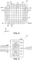
- FIG. 8 is a plan view illustrating the input device 2A according to Embodiment 2.
- FIG. 9 is a block diagram illustrating a configuration of the input device 2A according to Embodiment 2.
- the same components as those in Embodiment 1 are denoted by the same reference numerals, and the description thereof is omitted.
- respective configurations of a first detection unit 6A and a second detection unit 8A are different from the configurations in Embodiment 1.
- the first detection unit 6A includes an optical array sensor, and has a plurality of first light emitting units 44, a plurality of first light receiving units 46, a plurality of second light emitting units 48, and a plurality of second light receiving units 50.
- the plurality of first light emitting units 44 is disposed at intervals along a first side 52a of the display unit 4.
- the plurality of first light receiving units 46 is disposed at intervals along a second side 52b facing the first side 52a of the display unit 4. That is, each of the plurality of first light emitting units 44 is disposed corresponding to each of the plurality of first light receiving units 46.
- Each of the plurality of first light emitting units 44 linearly irradiates an infrared ray (indicated by a one-dot chain line in FIG. 8 ) toward the plurality of first light receiving units 46.
- Each of the plurality of first light receiving units 46 receives the infrared ray from the plurality of first light emitting units 44.
- the plurality of second light emitting units 48 is disposed at intervals along a third side 52c of the display unit 4.
- the plurality of second light receiving units 50 is disposed at intervals along a fourth side 52d facing the third side 52c of the display unit 4. That is, each of the plurality of second light emitting units 48 is disposed corresponding to each of the plurality of second light receiving units 50.
- Each of the plurality of second light emitting units 48 linearly irradiates an infrared ray (indicated by a one-dot chain line in FIG. 8 ) toward the plurality of second light receiving units 50.
- Each of the plurality of second light receiving units 50 receives the infrared ray from the plurality of second light emitting units 48.
- a first sensing layer 16A is formed in a region surrounded by the plurality of first light emitting units 44, the plurality of first light receiving units 46, the plurality of second light emitting units 48, and the plurality of second light receiving units 50.
- the object 18 passes through a predetermined position of the first sensing layer 16A, the light from the first light emitting unit 44 and the second light emitting unit 48 corresponding to the predetermined position is blocked by the object 18, and thus the light is not received by the first light receiving unit 46 and the second light receiving unit 50 corresponding to the predetermined position.
- the first detection unit 6A detects the size (area) of the object 18 at the predetermined position of the first sensing layer 16A.
- the second detection unit 8A detects the presence or absence of the object 18 in the second sensing layer 24. Similar to Embodiment 1, the second detection unit 8A includes a scan sensor. Moreover, the second detection unit 8A may include an optical array sensor similarly to the first detection unit 6A.
- the detection processing unit 32A computes the size of the object 18 in the first sensing layer 16A based on a detection signal from the first detection unit 6A. In addition, the detection processing unit 32A determines the presence or absence of the object 18 in the second sensing layer 24 based on a detection signal from the second detection unit 8A.
- the determination unit 36A determines the presence or absence of a specific non-contact operation performed on the operation screen 10 by the object 18 based on respective computation results of the detection processing unit 32A and the distance measurement calculation unit 34.
- the specific non-contact operation is a non-contact single touch gesture on the operation screen 10, for example. A determination process by the determination unit 36A will be described later in detail.
- FIG. 10 is a flowchart illustrating an operation flow of the input device 2A according to Embodiment 2.
- the first detection unit 6A detects the size of the object 18 in the first sensing layer 16A (S201).
- the detection processing unit 32A computes the size of the object 18 in the first sensing layer 16A based on a detection signal from the first detection unit 6A.
- the detection processing unit 32A determines that the size of the object 18 in the first sensing layer 16A is equal to or smaller than a threshold (YES in S202).
- the threshold is an area corresponding to the average size of one finger.
- the display control unit 40 displays the cursor 42 (see (b) of FIG. 5A ) on the operation screen 10 when the object 18 passes through the first sensing layer 16A (S203).
- the second detection unit 8A detects the presence of the object 18 (one finger) in the second sensing layer 24 (S204).
- the detection processing unit 32A determines that the object 18 is present in the second sensing layer 24 based on a detection signal from the second detection unit 8A.
- the determination unit 36A determines that a single touch gesture is performed when the object 18 passes through the second sensing layer 24 in a state that the cursor 42 is superimposed on the icon 14 (S205).
- step S202 when a wrist of the user passes through the first sensing layer 16A, the detection processing unit 32A determines that the size of the object 18 in the first sensing layer 16A exceeds the threshold (NO in S202). In this case, the display control unit 40 does not display the cursor 42 on the operation screen 10.
- the second detection unit 8A detects the presence of the object 18 (such as the wrist or the finger) in the second sensing layer 24 (S206).
- the detection processing unit 32A determines that the object 18 is present in the second sensing layer 24 based on a detection signal from the second detection unit 8A.
- the determination unit 36A determines that the single touch gesture is not performed (S207).
- the determination unit 36A determines the presence or absence of a specific non-contact operation performed by the object 18 based on the size of the object in the first sensing layer 16A and the presence or absence of the object 18 in the second sensing layer 24.
- the determination unit 36A determines that a specific non-contact operation on the operation screen 10 is performed.
- the determination unit 36A determines that a specific non-contact operation on the operation screen 10 is not performed.
- Embodiment 2 As in Embodiment 1, it is possible to precisely determine the presence or absence of a specific non-contact operation on the operation screen 10, and it is possible to avoid erroneous operation and the like of a device having the input device 2A as a user interface.
- Embodiment 1 and Embodiment 2 of the invention have been described above, but the invention is not limited to these embodiments. For example, the above respective embodiments may be combined.
- the operation screen 10 is displayed on the display surface 12 of the display unit 4 including the liquid crystal display panel.
- the operation screen may be, for example, an aerial image (real image) formed on a display surface which is an aerial display region, or may be a projection image projected on a display surface on a screen by a projector.
- the first detection unit 6 (6A) and the second detection unit 8 (8A) are separately configured.
- the invention is not limited thereto.
- These detection units may be integrally configured. That is, each function of the first detection unit 6 (6A) and the second detection unit 8 (8A) may be realized by one detection unit.
- the first sensing layer 16 (16A) and the second sensing layer 24 are formed in the air.
- the invention is not limited thereto, and one or a plurality of third sensing layers may be further formed in the air between the second sensing layer 24 and the display surface 12 of the display unit 4.
- the input device 2 (2A) includes one or a plurality of third detection units that detects a passing state of the object 18 in one or a plurality of third sensing layers, and the determination unit 36 determines the presence or absence of a specific non-contact operation performed by the object 18 based on a detection result of each of the first detection unit 6 (6A), the second detection unit 8 (8A), and the one or plurality of third detection units.
- the determination unit 36 may determine that a specific non-contact operation by the object 18 is performed when the object 18 passes through the third sensing layer formed at a position closest to the display surface 12 of the display unit 4.
- the object 18 is the finger of the user.
- the invention is not limited thereto, and the object 18 may be, for example, an indicator stick, etc.
- each of the above devices may be configured as a computer system including a microprocessor, a ROM (Read Only Memory), a RAM (Random Access Memory), a hard disk drive, a display unit, a keyboard, a mouse, etc.
- a computer program is stored in the RAM or the hard disk drive.
- Each device achieves a function thereof by the microprocessor operating according to the computer program.
- the computer program is configured by combining a plurality of instruction codes indicating instructions for the computer in order to achieve a predetermined function.
- the components configuring each of the aforementioned devices may be configured by a single system LSI (Large Scale Integration).
- the system LSI is an ultra-multifunctional LSI manufactured by integrating a plurality of components on a single chip.
- the system LSI is a computer system including a microprocessor, a ROM, a RAM, etc.
- a computer program is stored in the RAM
- the system LSI achieves functions thereof by the microprocessor operating according to the computer program.
- the components configuring each of the aforementioned devices may include an IC card or a single module that can be attached to and detached from each device.
- the IC card or the module is a computer system that includes a microprocessor, a ROM, a RAM, etc.
- the IC card or the module may include the ultra-multifunctional LSI described above.
- the IC card or the module achieves a function thereof by the microprocessor operating according to a computer program. This IC card or this module may have tamper resistance.
- the invention may be the aforementioned methods. Further, the invention may be a computer program that realizes these methods by a computer, or may be a digital signal including the computer program.
- the computer program or the digital signal may be recorded in a computer-readable non-transitory recording medium, for example, a flexible disk, a hard disk, a CD-ROM, an MO, a DVD, a DVD-ROM, a DVD-RAM, a BD, a semiconductor memory, etc.
- the invention may be the digital signal recorded in these non-transitory recording media.
- the computer program or the digital signal may be transmitted via an electric communication line, a wireless or wired communication line, a network represented by the Internet, a data broadcast, etc.
- the invention may be a computer system including a microprocessor and a memory, in which the memory stores the computer program, and the microprocessor operates according to the computer program.
- another independent computer system may be used for implementation by recording the program or the digital signal in the non-transitory recording medium and transferring the program or the digital signal or by transferring the program or the digital signal via the network, etc.
- each component may be configured by dedicated hardware or may be realized by executing a software program suitable for each component.
- Each component may be realized by a program execution unit such as a CPU or a processor reading and executing a software program recorded in a recording medium such as a hard disk or a semiconductor memory.
- the input device of the invention can be applied as, for example, a user interface for operating a device.
Landscapes
- Engineering & Computer Science (AREA)
- General Engineering & Computer Science (AREA)
- Theoretical Computer Science (AREA)
- Human Computer Interaction (AREA)
- Physics & Mathematics (AREA)
- General Physics & Mathematics (AREA)
- User Interface Of Digital Computer (AREA)
- Position Input By Displaying (AREA)
Abstract
Description
- The invention relates to an input device for receiving a specific non-contact operation performed on an operation screen by an object.
- In the food processing field and the medical field where hygiene management is strict, it is not preferable to use a touch panel display with which a finger of a user is in direct contact since the touch panel display may become a pathogen infection source. For this reason, in each of the aforementioned fields, it has been proposed to use an input device for receiving a specific non-contact operation performed on the operation screen by the finger of the user (for example, see patent literature 1).
- A conventional input device forms an aerial image (real image) indicating an operation screen in an aerial display area, and detects movement of a finger of a user in a detection area facing the aerial image, thereby determining that a specific non-contact operation on the operation screen has been performed.
- [Patent Literature 1] Japanese Patent Application Laid-open No.
2014-67071 - However, in the aforementioned conventional input device, for example, when a part of the body of the user unintentionally passes through the detection area, there is a risk of erroneous determination that a specific non-contact operation on the operation screen has been performed.
- The invention is intended to solve the aforementioned problem, and an object of the invention is to provide an input device that can precisely determine the presence or absence of a specific non-contact operation on an operation screen.
- To achieve the above object, according to one embodiment of the invention, it provides an input device for receiving a specific non-contact operation performed on an operation screen by an object, including: a display control unit that displays the operation screen on a display surface; a first detection unit that detects a passing state of the object in a first sensing layer in air formed to face the display surface; a second detection unit that detects a passing state of the object in a second sensing layer in air formed between the display surface and the first sensing layer, and a determination unit that determines presence or absence of the specific non-contact operation performed by the object based on respective detection results of the first detection unit and the second detection unit.
- According to this embodiment, the passing state of the object in each of the first sensing layer and the second sensing layer is different between the case in which a user intentionally performs the specific non-contact operation on the operation screen and the case in which a part of the body of the user or the like unintentionally passes through each of the first sensing layer and the second sensing layer. For this reason, by determining the presence or absence of the specific non-contact operation performed by the object based on the passing state of the object in each of the first sensing layer and the second sensing layer, the determination unit can precisely determine the presence or absence of the specific non-contact operation on the operation screen. As a result, it is possible to avoid an erroneous operation and the like of a device having the input device as a user interface.
- For example, in the input device according to one embodiment of the invention, the first detection unit may detect the number of passage places of the object in the first sensing layer, and the second detection unit may detect the number of passage places of the object in the second sensing layer.
- According to this embodiment, the determination unit can determine the presence or absence of the specific non-contact operation performed by the object based on the number of passage places of the object in each of the first sensing layer and the second sensing layer.
- For example, in the input device according to one embodiment of the invention, the specific non-contact operation may be a non-contact single touch gesture for a predetermined display on the operation screen made by the object, and when the object passes through the first sensing layer at one place and passes through the second sensing layer at one place, the determination unit determines that the single touch gesture is performed.
- According to this embodiment, the determination unit can determine that the single touch gesture is performed based on the number of passage places of the object in each of the first sensing layer and the second sensing layer.
- For example, in the input device according to one embodiment of the invention, the specific non-contact operation may be a non-contact multi-touch gesture on the operation screen made by the object, and when the object passes through the first sensing layer at two places and passes through the second sensing layer at two places, the determination unit determines that the multi-touch gesture is performed.
- According to this embodiment, the determination unit can determine that the multi-touch gesture is performed based on the number of passage places of the object in each of the first sensing layer and the second sensing layer.
- For example, in the input device according to one embodiment of the invention, when the object passes through the first sensing layer at three places or more and passes through the second sensing layer at one place or more, the determination unit may determine that the specific non-contact operation is not performed.
- According to this embodiment, the determination unit can determine that the specific non-contact operation is not performed based on the number of passage places of the object in each of the first sensing layer and the second sensing layer.
- For example, in the input device according to one embodiment of the invention, when the object passes through the first sensing layer, the display control unit may display a cursor on the operation screen.
- According to this embodiment, since the display control unit displays a cursor on the operation screen when the object passes through the first sensing layer, the user can easily recognize that the object passes through the first sensing layer.
- For example, in the input device according to one embodiment of the invention, the first detection unit may detect a size of the object in the first sensing layer, the second detection unit may detect presence or absence of the object in the second sensing layer, and the determination unit may determine that the specific non-contact operation is performed when the size of the object in the first sensing layer is smaller than or equal to a threshold and the object is detected in the second sensing layer, and determine that the specific non-contact operation is not performed when the size of the object in the first sensing layer exceeds the threshold and the object is detected in the second sensing layer.
- According to this embodiment, the determination unit can determine the presence or absence of the specific non-contact operation performed by the object based on the size of the object in the first sensing layer and the presence or absence of the object in the second sensing layer.
- For example, in the input device according to one embodiment of the invention, the input device may further include one or a plurality of third detection units that detects a passing state of the object in one or a plurality of third sensing layers in air formed between the display surface and the second sensing layer, and the determination unit determines the presence or absence of the specific non-contact operation performed by the object based on respective detection results of the first detection unit, the second detection unit, and the one or plurality of third detection units.
- According to this embodiment, the determination unit can more precisely determine the presence or absence of the specific non-contact operation on the operation screen.
- Moreover, the invention can be realized as a program for causing a computer to function as a characteristic processing unit included in an input device or a program for causing a computer to execute characteristic steps included in an aerial image display method. Needless to say, such a program can be distributed via a computer-readable non-temporary recording medium such as a CD-ROM (Compact Disc-Read Only Memory) or a communication network such as the Internet.
- According to the input device of the embodiment of the invention, it is possible to precisely determine the presence or absence of a specific non-contact operation on an operation screen.
-
-
FIG. 1 is a plan view illustrating an input device according toEmbodiment 1. -
FIG. 2 is a side view illustrating the input device according toEmbodiment 1. -
FIG. 3 is a block diagram illustrating a configuration of the input device according toEmbodiment 1. -
FIG. 4 is a flowchart illustrating an operation flow of the input device according toEmbodiment 1. -
FIG. 5A is a diagram for description of a state in which an object passes through a first sensing layer at one place in the input device according toEmbodiment 1. -
FIG. 5B is a diagram for description of a state in which the object passes through a second sensing layer at one place in the input device according toEmbodiment 1. -
FIG.6 is a diagram for description of a state in which the object passes through each of the first sensing layer and the second sensing layer at two places in the input device according toEmbodiment 1. -
FIG.7 is a diagram for description of a state in which the object passes through each of the first sensing layer and the second sensing layer at three places in the input device according toEmbodiment 1. -
FIG. 8 is a plan view illustrating an input device according toEmbodiment 2. -
FIG. 9 is a block diagram illustrating a configuration of the input device according toEmbodiment 2. -
FIG. 10 is a flowchart illustrating an operation flow of the input device according toEmbodiment 2. - Hereinafter, embodiments of the invention will be described in detail with reference to the drawings. Moreover, it should be noted that each of the embodiments described below shows a comprehensive or specific example. Numerical values, shapes, materials, components, arrangement positions and connection forms of the components, etc. shown in the following embodiments are merely examples, and are not intended to limit the invention. In addition, among the components in the following embodiments, components that are not described in the independent claims are described as arbitrary components.
- First, a configuration of an
input device 2 according toEmbodiment 1 is described with reference toFIG. 1 to FIG. 3 .FIG. 1 is a plan view illustrating theinput device 2 according toEmbodiment 1.FIG. 2 is a side view illustrating theinput device 2 according toEmbodiment 1.FIG. 3 is a block diagram illustrating a configuration of theinput device 2 according toEmbodiment 1. - As illustrated in
FIG. 1 andFIG. 2 , theinput device 2 includes adisplay unit 4, afirst detection unit 6, and asecond detection unit 8. Theinput device 2 is applied as a user interface for operating a device (not illustrated) used in, for example, the food processing field or the medical field in a non-contact manner by an object 18 (for example, a finger of a user). - The
display unit 4 is, for example, a liquid crystal display panel. Thedisplay unit 4 has adisplay surface 12 for displaying anoperation screen 10. Theoperation screen 10 is, for example, a menu screen or the like for operating the device. In the example illustrated inFIG. 1 , an icon 14 (an example of a predetermined display) indicating an operation menu or the like of the device is displayed on theoperation screen 10. - The
first detection unit 6 detects a passing state of theobject 18 in afirst sensing layer 16 in air formed to face thedisplay surface 12 of thedisplay unit 4. Specifically, thefirst detection unit 6 detects the number of passage places of theobject 18 in thefirst sensing layer 16. - The
first sensing layer 16 corresponds to a virtual plane (XY plane) formed at an aerial position substantially parallel to thedisplay surface 12 of thedisplay unit 4. In addition, the passage place of theobject 18 in thefirst sensing layer 16 refers to a cross-sectional region of theobject 18 in thefirst sensing layer 16. For example, when one finger of the user passes through thefirst sensing layer 16, there is one passage place of theobject 18 in thefirst sensing layer 16. Further, for example, when two fingers of the user pass through thefirst sensing layer 16, there are two passage places of theobject 18 in thefirst sensing layer 16. - The
first detection unit 6 includes, for example, a scan sensor, and is disposed to face a corner of thedisplay unit 4 as illustrated inFIG. 1 . As illustrated inFIG. 2 , thefirst detection unit 6 includes a first light emitting unit 20 and a first light receiving unit 22. The first light emitting unit 20 scans an infrared laser in thefirst sensing layer 16 in two-dimensional manner. The first light receiving unit 22 receives and detects light reflected by theobject 18 passing through thefirst sensing layer 16. - The
second detection unit 8 detects a passing state of theobject 18 in asecond sensing layer 24 in air formed between thedisplay surface 12 of thedisplay unit 4 and thefirst sensing layer 16. Specifically, thesecond detection unit 8 detects the number of passage places of theobject 18 in thesecond sensing layer 24. As illustrated inFIG. 2 , a distance D between thesecond sensing layer 24 and thedisplay surface 12 of thedisplay unit 4 is a size (for example, about 1 cm to several centimeters) at which theobject 18 does not directly come into contact with thedisplay surface 12 of thedisplay unit 4 when theobject 18 passes through thesecond sensing layer 24. - Moreover, the
second sensing layer 24 is a virtual plane (XY plane) formed at an aerial position substantially parallel to thedisplay surface 12 of thedisplay unit 4. In addition, the passage place of theobject 18 in thesecond sensing layer 24 refers to a cross-sectional region of theobject 18 in thesecond sensing layer 24. For example, when one finger of the user passes through thesecond sensing layer 24, there are one passage place of theobject 18 in thesecond sensing layer 24. Further, for example, when two fingers of the user pass through thesecond sensing layer 24, there are two passage places of theobject 18 in thesecond sensing layer 24. - The
second detection unit 8 includes, for example, a scan sensor, and is disposed to face the corner of thedisplay unit 4 as illustrated inFIG. 1 . As illustrated inFIG. 2 , thesecond detection unit 8 includes a second light emitting unit 26 and a second light receiving unit 28. The second light emitting unit 26 scans an infrared laser in thesecond sensing layer 24 in a two-dimensional manner. The second light receiving unit 28 receives and detects light reflected by theobject 18 passing through thesecond sensing layer 24. - As illustrated in
FIG. 3 , theinput device 2 further includes acalculation processing unit 30. Thecalculation processing unit 30 includes adetection processing unit 32, a distancemeasurement calculation unit 34, adetermination unit 36, anoperation processing unit 38, and adisplay control unit 40. - The
detection processing unit 32 computes the number of passage places of theobject 18 in thefirst sensing layer 16 based on a detection signal from thefirst detection unit 6. In addition, thedetection processing unit 32 computes the number of passage places of theobject 18 in thesecond sensing layer 24 based on a detection signal from thesecond detection unit 8. - The distance
measurement calculation unit 34 computes a position (two-dimensional coordinates) of theobject 18 in thefirst sensing layer 16 based on a detection signal from thefirst detection unit 6. In addition, the distancemeasurement calculation unit 34 computes a position (two-dimensional coordinates) of theobject 18 in thesecond sensing layer 24 based on a detection signal from thesecond detection unit 8. - The
determination unit 36 determines the presence or absence of a specific non-contact operation performed on theoperation screen 10 made by theobject 18 based on respective computation results of thedetection processing unit 32 and the distancemeasurement calculation unit 34. Moreover, the specific non-contact operation is, for example, a non-contact single touch gesture, multi-touch gesture, etc. performed by the finger of the user on theoperation screen 10. The single touch gesture is a gesture performed by one finger (for example, the index finger) of the user, and is, for example, a gesture such as a tap. The multi-touch gesture is a gesture performed by two fingers (for example, the index finger and the thumb) of the user, and is, for example, a gesture such as pinch-in, pinch-out, rotation, etc. A determination process by thedetermination unit 36 will be described later in detail. - The
operation processing unit 38 executes processing corresponding to the specific non-contact operation based on a computation result of the distancemeasurement calculation unit 34 and a determination result of thedetermination unit 36. For example, when the user performs a single touch gesture on theicon 14 on theoperation screen 10 in a non-contact manner, theoperation processing unit 38 executes a process of selecting theicon 14, etc. In addition, for example, when the user performs a multi-touch gesture on theoperation screen 10 in a non-contact manner, theoperation processing unit 38 executes a process of enlarging or reducing the display magnification of theoperation screen 10, etc. - The
display control unit 40 controls display content on thedisplay surface 12 of thedisplay unit 4. Specifically, thedisplay control unit 40 executes a process of displaying theoperation screen 10 on thedisplay surface 12 of thedisplay unit 4. In addition, based on respective computation results of thedetection processing unit 32 and the distancemeasurement calculation unit 34, thedisplay control unit 40 executes a process of displaying a cursor 42 (see (b) ofFIG. 5A described later) on theoperation screen 10 when theobject 18 passes through thefirst sensing layer 16. In this instance, thecursor 42 is displayed at a position on theoperation screen 10 corresponding to a position of theobject 18 in thefirst sensing layer 16. - Next, an operation of the
input device 2 according toEmbodiment 1 is described with reference toFIG. 4 to FIG. 7 .FIG. 4 is a flowchart illustrating an operation flow of theinput device 2 according toEmbodiment 1.FIG. 5A is a diagram for description of a state in which theobject 18 passes through thefirst sensing layer 16 at one place in theinput device 2 according toEmbodiment 1.FIG. 5B is a diagram for description of a state in which theobject 18 passes through thesecond sensing layer 24 at one place in theinput device 2 according toEmbodiment 1.FIG.6 is a diagram for description of a state in which theobject 18 passes through each of thefirst sensing layer 16 and thesecond sensing layer 24 at two places in theinput device 2 according toEmbodiment 1.FIG.7 is a diagram for description of a state in which theobject 18 passes through each of thefirst sensing layer 16 and thesecond sensing layer 24 at three places in theinput device 2 according toEmbodiment 1. - First, an operation of the
input device 2 in the case that the user performs a single touch gesture is described with reference toFIG. 4 to FIG. 5B . - As illustrated in
FIG. 4 and (a) ofFIG. 5A , when one finger of the user passes through thefirst sensing layer 16, thefirst detection unit 6 detects the number of passage places of the object 18 (one finger) in the first sensing layer 16 (S101). Thedetection processing unit 32 computes the number of passage places of theobject 18 in thefirst sensing layer 16 as "one place" based on a detection signal from the first detection unit 6 ("one place" in S102). - As illustrated in (b) of
FIG. 5A , thedisplay control unit 40 displays thecursor 42 on theoperation screen 10 when theobject 18 passes through thefirst sensing layer 16 based on respective computation results of thedetection processing unit 32 and the distance measurement calculation unit 34 (S103). In this state, by the user moving one finger along the first sensing layer 16 (that is, in the XY plane), thecursor 42 moves on theoperation screen 10 following movement of the finger of the user. A sound may be output from a speaker (not illustrated) of thedisplay unit 4 at the same time as thecursor 42 is displayed on theoperation screen 10. - Thereafter, as illustrated in (a) of
FIG. 5B , when the user passes one finger through thesecond sensing layer 24, thesecond detection unit 8 detects the number of passage places of the object 18 (one finger) in the second sensing layer 24 (S104). Thedetection processing unit 32 computes the number of passage places of theobject 18 in thesecond sensing layer 24 as "one place" based on a detection signal from thesecond detection unit 8. Moreover, when one finger of the user passes through thefirst sensing layer 16, there is one passage place of theobject 18 in thesecond sensing layer 24 at all times. As illustrated in (b) ofFIG. 5B , when theobject 18 passes through thesecond sensing layer 24 at one place in a state that thecursor 42 is superimposed on theicon 14, thedetermination unit 36 determines that a single touch gesture is performed (S105). - Moreover, when the single touch gesture is performed, a dedicated button or icon other than the
icon 14 may be displayed on theoperation screen 10. - Next, an operation of the
input device 2 when the user performs a multi-touch gesture is described with reference toFIG. 4 andFIG. 6 . - As illustrated in
FIG. 4 and (a) ofFIG. 6 , when two fingers (for example, index finger and thumb) of the user pass through thefirst sensing layer 16, thefirst detection unit 6 detects the number of passage places of the object 18 (two fingers) in the sensing layer 16 (S101). Thedetection processing unit 32 computes the number of passage places of theobject 18 in thesensing layer 16 as "two places" based on a detection signal from the first detection unit 6 ("two places" in S102). - Based on respective computation results of the
detection processing unit 32 and the distancemeasurement calculation unit 34, thedisplay control unit 40 displays the cursor 42 (see (b) ofFIG. 5A ) on theoperation screen 10 when theobject 18 passes through the first sensing layer 16 (S106). - Thereafter, when the user passes the finger through the
second sensing layer 24, thesecond detection unit 8 detects the number of passage places of the object 18 (finger) in the second sensing layer 24 (S107). Moreover, when two fingers of the user pass through thefirst sensing layer 16, the number of passage places of theobject 18 in thesecond sensing layer 24 is two or one. - As illustrated in (b) of
FIG. 6 , when two fingers of the user pass through thesecond sensing layer 24, thedetection processing unit 32 computes the number of passage places of theobject 18 in thesecond sensing layer 24 as "two places" based on a detection signal from the second detection unit 8 ("two places" in S108). When theobject 18 passes through thesecond sensing layer 24 at two places, thedetermination unit 36 determines that a multi-touch gesture has been performed (S109). - On the other hand, when one finger of the user passes through the
second sensing layer 24, thedetection processing unit 32 computes the number of passage places of theobject 18 in thesecond sensing layer 24 as "one place" based on a detection signal from the second detection unit 8 ("one place" in S108). Thedetermination unit 36 determines that a single touch gesture is performed after a predetermined waiting time elapses from the time theobject 18 passes through thesecond sensing layer 24 at one place (S105). - Next, an operation of the
input device 2 when three fingers of the user unintentionally pass through each of thefirst sensing layer 16 and thesecond sensing layer 24 is described with reference toFIG. 4 andFIG. 7 . - As illustrated in
FIG. 4 and (a) ofFIG. 7 , when three fingers (for example, index finger, middle finger, and ring finger) of the user pass through thefirst sensing layer 16, thefirst detection unit 6 detects the number of passage places of the object 18 (three fingers) in the first sensing layer 16 (S101). Thedetection processing unit 32 computes the number of passage places of theobject 18 in thefirst sensing layer 16 as "three places" based on a detection signal from the first detection unit 6 ("three places" in S102). - Based on respective computation results of the
detection processing unit 32 and the distancemeasurement calculation unit 34, thedisplay control unit 40 displays the cursor 42 (see (b) ofFIG. 5A ) on theoperation screen 10 when theobject 18 passes through the first sensing layer 16 (S110). - Thereafter, when the fingers of the user pass through the
second sensing layer 24, thesecond detection unit 8 detects the number of passage places of the object 18 (finger) in the second sensing layer 24 (S111). Moreover, when three fingers of the user pass through thefirst sensing layer 16, the number of passage places of theobject 18 in thesecond sensing layer 24 is three or fewer. - As illustrated in (b) of
FIG. 7 , when three fingers of the user pass through thesecond sensing layer 24, thedetection processing unit 32 computes the number of passage places of theobject 18 in thesecond sensing layer 24 as "three places" based on a detection signal from thesecond detection unit 8. When theobject 18 passes through thesecond sensing layer 24 at three places, thedetermination unit 36 determines that neither the single touch gesture nor the multi-touch gesture is performed (S112). In this instance, similarly to the case in which theobject 18 passes through thesecond sensing layer 24 at two places or one place, thedetermination unit 36 determines that neither single touch gesture nor multi-touch gesture is performed. - Moreover, when the
object 18 passes through thefirst sensing layer 16 at four or more places, the process proceeds from step S102 to S110 in the same manner as described above to execute respective processes of S110 to S112, and it is determined that neither single touch gesture nor multi-touch gesture is performed. - As described above, the
determination unit 36 determines the presence or absence of a specific non-contact operation performed by theobject 18 based on the number of passage places of theobject 18 in each of thefirst sensing layer 16 and thesecond sensing layer 24. - For example, when the user intentionally performs a specific non-contact operation on the
operation screen 10, the number of passage places of theobject 18 in thefirst sensing layer 16 is considered to be one or two. Therefore, in this case, thedetermination unit 36 determines that the specific non-contact operation on theoperation screen 10 is performed. - On the other hand, for example, when a part of the body or the like of the user unintentionally passes through the
first sensing layer 16, the number of passage places of theobject 18 in thefirst sensing layer 16 is considered to be three or more. Therefore, in this case, thedetermination unit 36 determines that the specific non-contact operation on theoperation screen 10 is not performed. - Therefore, in the
input device 2 according toEmbodiment 1, it is possible to precisely determine the presence or absence of a specific non-contact operation on theoperation screen 10, and it is possible to avoid an erroneous operation and the like of a device having theinput device 2 as a user interface. - Next, a configuration of an
input device 2A according toEmbodiment 2 is described with reference toFIG. 8 and FIG. 9. FIG. 8 is a plan view illustrating theinput device 2A according toEmbodiment 2.FIG. 9 is a block diagram illustrating a configuration of theinput device 2A according toEmbodiment 2. Moreover, in the present embodiment, the same components as those inEmbodiment 1 are denoted by the same reference numerals, and the description thereof is omitted. - As illustrated in
FIG. 8 , in theinput device 2A according toEmbodiment 2, respective configurations of afirst detection unit 6A and asecond detection unit 8A are different from the configurations inEmbodiment 1. - Specifically, the
first detection unit 6A includes an optical array sensor, and has a plurality of firstlight emitting units 44, a plurality of firstlight receiving units 46, a plurality of secondlight emitting units 48, and a plurality of secondlight receiving units 50. - The plurality of first
light emitting units 44 is disposed at intervals along afirst side 52a of thedisplay unit 4. The plurality of firstlight receiving units 46 is disposed at intervals along asecond side 52b facing thefirst side 52a of thedisplay unit 4. That is, each of the plurality of firstlight emitting units 44 is disposed corresponding to each of the plurality of firstlight receiving units 46. Each of the plurality of firstlight emitting units 44 linearly irradiates an infrared ray (indicated by a one-dot chain line inFIG. 8 ) toward the plurality of firstlight receiving units 46. Each of the plurality of firstlight receiving units 46 receives the infrared ray from the plurality of firstlight emitting units 44. - The plurality of second
light emitting units 48 is disposed at intervals along athird side 52c of thedisplay unit 4. The plurality of secondlight receiving units 50 is disposed at intervals along afourth side 52d facing thethird side 52c of thedisplay unit 4. That is, each of the plurality of secondlight emitting units 48 is disposed corresponding to each of the plurality of secondlight receiving units 50. Each of the plurality of secondlight emitting units 48 linearly irradiates an infrared ray (indicated by a one-dot chain line inFIG. 8 ) toward the plurality of secondlight receiving units 50. Each of the plurality of secondlight receiving units 50 receives the infrared ray from the plurality of secondlight emitting units 48. - A first sensing layer 16A is formed in a region surrounded by the plurality of first
light emitting units 44, the plurality of firstlight receiving units 46, the plurality of secondlight emitting units 48, and the plurality of secondlight receiving units 50. When the object 18 (seeFIG. 2 ) passes through a predetermined position of the first sensing layer 16A, the light from the firstlight emitting unit 44 and the secondlight emitting unit 48 corresponding to the predetermined position is blocked by theobject 18, and thus the light is not received by the firstlight receiving unit 46 and the secondlight receiving unit 50 corresponding to the predetermined position. Accordingly, thefirst detection unit 6A detects the size (area) of theobject 18 at the predetermined position of the first sensing layer 16A. - In addition, the
second detection unit 8A detects the presence or absence of theobject 18 in thesecond sensing layer 24. Similar toEmbodiment 1, thesecond detection unit 8A includes a scan sensor. Moreover, thesecond detection unit 8A may include an optical array sensor similarly to thefirst detection unit 6A. - Furthermore, as illustrated in
FIG. 9 , in theinput device 2A according toEmbodiment 2, respective configurations of adetection processing unit 32A and adetermination unit 36A of acalculation processing unit 30A are different from those inEmbodiment 1. - The
detection processing unit 32A computes the size of theobject 18 in the first sensing layer 16A based on a detection signal from thefirst detection unit 6A. In addition, thedetection processing unit 32A determines the presence or absence of theobject 18 in thesecond sensing layer 24 based on a detection signal from thesecond detection unit 8A. - The
determination unit 36A determines the presence or absence of a specific non-contact operation performed on theoperation screen 10 by theobject 18 based on respective computation results of thedetection processing unit 32A and the distancemeasurement calculation unit 34. In the present embodiment, the specific non-contact operation is a non-contact single touch gesture on theoperation screen 10, for example. A determination process by thedetermination unit 36A will be described later in detail. - Next, an operation of the
input device 2A according toEmbodiment 2 is described with reference toFIG. 10. FIG. 10 is a flowchart illustrating an operation flow of theinput device 2A according toEmbodiment 2. - As illustrated in
FIG. 10 , when theobject 18 passes through the first sensing layer 16A, thefirst detection unit 6A detects the size of theobject 18 in the first sensing layer 16A (S201). Thedetection processing unit 32A computes the size of theobject 18 in the first sensing layer 16A based on a detection signal from thefirst detection unit 6A. - When one finger of the user passes through the first sensing layer 16A, the
detection processing unit 32A determines that the size of theobject 18 in the first sensing layer 16A is equal to or smaller than a threshold (YES in S202). Here, for example, the threshold is an area corresponding to the average size of one finger. Based on respective computation results of thedetection processing unit 32A and the distancemeasurement calculation unit 34, thedisplay control unit 40 displays the cursor 42 (see (b) ofFIG. 5A ) on theoperation screen 10 when theobject 18 passes through the first sensing layer 16A (S203). - Thereafter, when one finger of the user passes through the
second sensing layer 24, thesecond detection unit 8A detects the presence of the object 18 (one finger) in the second sensing layer 24 (S204). Thedetection processing unit 32A determines that theobject 18 is present in thesecond sensing layer 24 based on a detection signal from thesecond detection unit 8A. Thedetermination unit 36A determines that a single touch gesture is performed when theobject 18 passes through thesecond sensing layer 24 in a state that thecursor 42 is superimposed on the icon 14 (S205). - Returning to step S202 described above, for example, when a wrist of the user passes through the first sensing layer 16A, the
detection processing unit 32A determines that the size of theobject 18 in the first sensing layer 16A exceeds the threshold (NO in S202). In this case, thedisplay control unit 40 does not display thecursor 42 on theoperation screen 10. - Thereafter, when the wrist, the finger, or the like of the user passes through the
second sensing layer 24, thesecond detection unit 8A detects the presence of the object 18 (such as the wrist or the finger) in the second sensing layer 24 (S206). Thedetection processing unit 32A determines that theobject 18 is present in thesecond sensing layer 24 based on a detection signal from thesecond detection unit 8A. When theobject 18 passes through thesecond sensing layer 24, thedetermination unit 36A determines that the single touch gesture is not performed (S207). - As described above, the
determination unit 36A determines the presence or absence of a specific non-contact operation performed by theobject 18 based on the size of the object in the first sensing layer 16A and the presence or absence of theobject 18 in thesecond sensing layer 24. - For example, when the user intentionally performs a specific non-contact operation on the
operation screen 10, the size of theobject 18 in the first sensing layer 16A is considered to be smaller than or equal to the threshold. Therefore, in this case, thedetermination unit 36A determines that a specific non-contact operation on theoperation screen 10 is performed. - On the other hand, for example, when a part of the body or the like of the user unintentionally passes through the first sensing layer 16A, the size of the
object 18 in the first sensing layer 16A is considered to exceed the threshold. Therefore, in this case, thedetermination unit 36A determines that a specific non-contact operation on theoperation screen 10 is not performed. - Therefore, in the
input device 2A according toEmbodiment 2, as inEmbodiment 1, it is possible to precisely determine the presence or absence of a specific non-contact operation on theoperation screen 10, and it is possible to avoid erroneous operation and the like of a device having theinput device 2A as a user interface. - The input devices according to
Embodiment 1 andEmbodiment 2 of the invention have been described above, but the invention is not limited to these embodiments. For example, the above respective embodiments may be combined. - In each of the aforementioned embodiments, the
operation screen 10 is displayed on thedisplay surface 12 of thedisplay unit 4 including the liquid crystal display panel. However, the invention is not limited thereto. The operation screen may be, for example, an aerial image (real image) formed on a display surface which is an aerial display region, or may be a projection image projected on a display surface on a screen by a projector. - In addition, in each of the above embodiments, the first detection unit 6 (6A) and the second detection unit 8 (8A) are separately configured. However, the invention is not limited thereto. These detection units may be integrally configured. That is, each function of the first detection unit 6 (6A) and the second detection unit 8 (8A) may be realized by one detection unit.
- In addition, in each of the above embodiments, the first sensing layer 16 (16A) and the
second sensing layer 24 are formed in the air. However, the invention is not limited thereto, and one or a plurality of third sensing layers may be further formed in the air between thesecond sensing layer 24 and thedisplay surface 12 of thedisplay unit 4. In this case, the input device 2 (2A) includes one or a plurality of third detection units that detects a passing state of theobject 18 in one or a plurality of third sensing layers, and thedetermination unit 36 determines the presence or absence of a specific non-contact operation performed by theobject 18 based on a detection result of each of the first detection unit 6 (6A), the second detection unit 8 (8A), and the one or plurality of third detection units. Moreover, thedetermination unit 36 may determine that a specific non-contact operation by theobject 18 is performed when theobject 18 passes through the third sensing layer formed at a position closest to thedisplay surface 12 of thedisplay unit 4. - In addition, in each of the above embodiments, the
object 18 is the finger of the user. However, the invention is not limited thereto, and theobject 18 may be, for example, an indicator stick, etc. - In addition, specifically, each of the above devices may be configured as a computer system including a microprocessor, a ROM (Read Only Memory), a RAM (Random Access Memory), a hard disk drive, a display unit, a keyboard, a mouse, etc. A computer program is stored in the RAM or the hard disk drive. Each device achieves a function thereof by the microprocessor operating according to the computer program. Here, the computer program is configured by combining a plurality of instruction codes indicating instructions for the computer in order to achieve a predetermined function.
- Furthermore, some or all of the components configuring each of the aforementioned devices may be configured by a single system LSI (Large Scale Integration). The system LSI is an ultra-multifunctional LSI manufactured by integrating a plurality of components on a single chip. Specifically, the system LSI is a computer system including a microprocessor, a ROM, a RAM, etc. A computer program is stored in the RAM The system LSI achieves functions thereof by the microprocessor operating according to the computer program.
- Furthermore, some or all of the components configuring each of the aforementioned devices may include an IC card or a single module that can be attached to and detached from each device. The IC card or the module is a computer system that includes a microprocessor, a ROM, a RAM, etc. The IC card or the module may include the ultra-multifunctional LSI described above. The IC card or the module achieves a function thereof by the microprocessor operating according to a computer program. This IC card or this module may have tamper resistance.
- In addition, the invention may be the aforementioned methods. Further, the invention may be a computer program that realizes these methods by a computer, or may be a digital signal including the computer program.
- Furthermore, in the invention, the computer program or the digital signal may be recorded in a computer-readable non-transitory recording medium, for example, a flexible disk, a hard disk, a CD-ROM, an MO, a DVD, a DVD-ROM, a DVD-RAM, a BD, a semiconductor memory, etc. In addition, the invention may be the digital signal recorded in these non-transitory recording media.
- In addition, in the invention, the computer program or the digital signal may be transmitted via an electric communication line, a wireless or wired communication line, a network represented by the Internet, a data broadcast, etc.
- In addition, the invention may be a computer system including a microprocessor and a memory, in which the memory stores the computer program, and the microprocessor operates according to the computer program.
- In addition, another independent computer system may be used for implementation by recording the program or the digital signal in the non-transitory recording medium and transferring the program or the digital signal or by transferring the program or the digital signal via the network, etc.
- Moreover, in each of the above embodiments, each component may be configured by dedicated hardware or may be realized by executing a software program suitable for each component. Each component may be realized by a program execution unit such as a CPU or a processor reading and executing a software program recorded in a recording medium such as a hard disk or a semiconductor memory.
- The input device of the invention can be applied as, for example, a user interface for operating a device.
-
- 2, 2A
- input device
- 4
- display unit
- 6, 6A
- first detection unit
- 8, 8A
- second detection unit
- 10
- operation screen
- 12
- display surface
- 14
- icon
- 16, 16A
- first sensing layer
- 18
- object
- 20, 44
- first light emitting unit
- 22, 46
- first light receiving unit
- 24, 24A
- second sensing layer
- 26, 48
- second light emitting unit
- 28, 50
- second light receiving unit
- 30
- calculation processing unit
- 32
- detection processing unit
- 34
- distance measurement calculation unit
- 36
- determination unit
- 38
- operation processing unit
- 40
- display control unit
- 42
- cursor
- 52a
- first side
- 52b
- second side
- 52c
- third side
- 52d
- fourth side
Claims (8)
- An input device (2) for receiving a specific non-contact operation performed on an operation screen (10) by an object (18), characterized in that the input device (2) comprises:a display control unit (40) that displays the operation screen (10) on a display surface (12);a first detection unit (6) that detects a passing state of the object (18) in a first sensing layer (16) in air formed to face the display surface (12);a second detection unit (8) that detects a passing state of the object (18) in a second sensing layer (24) in air formed between the display surface (12) and the first sensing layer (16); anda determination unit (36) that determines presence or absence of the specific non-contact operation performed by the object (18) based on respective detection results of the first detection unit (6) and the second detection unit (8).
- The input device (2) according to claim 1, characterized in that
the first detection unit (6) detects a number of passage places of the object (18) in the first sensing layer (16), and
the second detection unit (8) detects a number of passage places of the object (18) in the second sensing layer (24). - The input device (2) according to claim 2, characterized in that
the specific non-contact operation is a non-contact single touch gesture for a predetermined display on the operation screen (10) made by the object (18), and
when the object (18) passes through the first sensing layer (16) at one place and passes through the second sensing layer (24) at one place, the determination unit (36) determines that the single touch gesture is performed. - The input device (2) according to claim 2 or 3, characterized in that
the specific non-contact operation is a non-contact multi-touch gesture on the operation screen (10) made by the object (18), and
when the object (18) passes through the first sensing layer (16) at two places and passes through the second sensing layer (24) at two places, the determination unit (36) determines that the multi-touch gesture is performed. - The input device (2) according to any one of claims 2 to 4, characterized in that when the object (18) passes through the first sensing layer (16) at three places or more and passes through the second sensing layer (24) at one place or more, the determination unit (36) determines that the specific non-contact operation is not performed.
- The input device (2) according to any one of claims 2 to 5, characterized in that when the object (18) passes through the first sensing layer (16), the display control unit (40) displays a cursor on the operation screen (10).
- The input device (2) according to claim 1, characterized in that
the first detection unit (6) detects a size of the object (18) in the first sensing layer (16),
the second detection unit (8) detects presence or absence of the object (18) in the second sensing layer (24), and
the determination unit (36)determines that the specific non-contact operation is performed when the size of the object (36) in the first sensing layer (16) is smaller than or equal to a threshold and the object (18) is detected in the second sensing layer (24), and
determines that the specific non-contact operation is not performed when the size of the object (18) in the first sensing layer (16) exceeds the threshold and the object (18) is detected in the second sensing layer (24). - The input device (2) according to claim 1, characterized in that
the input device (2) further includes one or a plurality of third detection units that detects a passing state of the object (18) in one or a plurality of third sensing layers in air formed between the display surface (12) and the second sensing layer (24), and
the determination unit (36) determines the presence or absence of the specific non-contact operation performed by the object (18) based on respective detection results of the first detection unit (6), the second detection unit (8), and the one or plurality of third detection units.
Applications Claiming Priority (1)
| Application Number | Priority Date | Filing Date | Title |
|---|---|---|---|
| JP2019070743A JP7400205B2 (en) | 2019-04-02 | 2019-04-02 | input device |
Publications (2)
| Publication Number | Publication Date |
|---|---|
| EP3719614A1 true EP3719614A1 (en) | 2020-10-07 |
| EP3719614B1 EP3719614B1 (en) | 2022-12-21 |
Family
ID=69779894
Family Applications (1)
| Application Number | Title | Priority Date | Filing Date |
|---|---|---|---|
| EP20161297.5A Active EP3719614B1 (en) | 2019-04-02 | 2020-03-05 | Input device |
Country Status (4)
| Country | Link |
|---|---|
| US (1) | US11068108B2 (en) |
| EP (1) | EP3719614B1 (en) |
| JP (1) | JP7400205B2 (en) |
| CN (1) | CN111796694B (en) |
Families Citing this family (11)
| Publication number | Priority date | Publication date | Assignee | Title |
|---|---|---|---|---|
| JP2022113036A (en) * | 2021-01-22 | 2022-08-03 | キヤノン株式会社 | Information processing equipment |
| FR3122751B1 (en) * | 2021-05-04 | 2023-10-06 | Imprimerie Nat | Detection kit for interactive terminal |
| JP7256842B2 (en) * | 2021-05-25 | 2023-04-12 | 株式会社エイサムテクノロジー | contactless input device |
| JP7694168B2 (en) * | 2021-06-07 | 2025-06-18 | ニプロ株式会社 | Input Devices and Medical Devices |
| WO2023016352A1 (en) * | 2021-08-13 | 2023-02-16 | 安徽省东超科技有限公司 | Positioning sensing method, positioning sensing apparatus, and input terminal device |
| US20250010178A1 (en) * | 2021-10-25 | 2025-01-09 | Sony Interactive Entertainment Inc. | Operating device |
| US11995359B2 (en) | 2021-12-14 | 2024-05-28 | Canon Kabushiki Kaisha | Image forming apparatus with touch and touchless input portion |
| JP2024067238A (en) | 2022-11-04 | 2024-05-17 | キヤノン株式会社 | Image forming device |
| JP2024073690A (en) | 2022-11-18 | 2024-05-30 | キヤノン株式会社 | Image forming device |
| JP2024101393A (en) * | 2023-01-17 | 2024-07-29 | Toppanホールディングス株式会社 | Aerial display devices and display devices |
| KR102875728B1 (en) * | 2023-04-28 | 2025-10-24 | 주식회사 켐트로닉스 | Icon selection method of contactless touch sensor |
Citations (6)
| Publication number | Priority date | Publication date | Assignee | Title |
|---|---|---|---|---|
| US20140028557A1 (en) * | 2011-05-16 | 2014-01-30 | Panasonic Corporation | Display device, display control method and display control program, and input device, input assistance method and program |
| JP2014067071A (en) | 2012-09-10 | 2014-04-17 | Askanet:Kk | Floating touch panel |
| US20160124514A1 (en) * | 2014-11-05 | 2016-05-05 | Samsung Electronics Co., Ltd. | Electronic device and method of controlling the same |
| US20170038861A1 (en) * | 2014-05-29 | 2017-02-09 | Fuji Electric Co., Ltd | Optical operating input detection apparatus, automatic vending machine, and optical operating input detection method |
| US20170308235A1 (en) * | 2014-12-26 | 2017-10-26 | Shenzhen China Star Optoelectronics Technology Co., Ltd. | Floating touch method |
| US20170329458A1 (en) * | 2014-12-08 | 2017-11-16 | Hitachi Maxell, Ltd. | Projection video display device and video display method |
Family Cites Families (11)
| Publication number | Priority date | Publication date | Assignee | Title |
|---|---|---|---|---|
| JPH06110610A (en) * | 1992-09-30 | 1994-04-22 | Toshiba Corp | Coordinate input device |
| JP2008009759A (en) * | 2006-06-29 | 2008-01-17 | Toyota Motor Corp | Touch panel device |
| JP5802667B2 (en) * | 2010-07-20 | 2015-10-28 | パナソニック インテレクチュアル プロパティ コーポレーション オブアメリカPanasonic Intellectual Property Corporation of America | Gesture input device and gesture input method |
| JP5880024B2 (en) * | 2011-12-22 | 2016-03-08 | 株式会社バッファロー | Information processing apparatus and program |
| US10394434B2 (en) * | 2013-02-22 | 2019-08-27 | Samsung Electronics Co., Ltd. | Apparatus and method for recognizing proximity motion using sensors |
| US10261612B2 (en) * | 2013-02-22 | 2019-04-16 | Samsung Electronics Co., Ltd. | Apparatus and method for recognizing proximity motion using sensors |
| US20150002475A1 (en) * | 2013-06-27 | 2015-01-01 | Industrial Technology Research Institute | Mobile device and method for controlling graphical user interface thereof |
| JP6359862B2 (en) * | 2014-04-17 | 2018-07-18 | シャープ株式会社 | Touch operation input device, touch operation input method, and program |
| CN105511675B (en) * | 2015-11-20 | 2020-07-24 | 重庆桔子科技发展有限公司 | Touch control method, user equipment, input processing method, mobile terminal and intelligent terminal |
| JP2017228216A (en) * | 2016-06-24 | 2017-12-28 | キヤノン株式会社 | Information processing apparatus, control method therefor, program, and storage medium |
| WO2018083737A1 (en) * | 2016-11-01 | 2018-05-11 | マクセル株式会社 | Display device and remote operation controller |
-
2019
- 2019-04-02 JP JP2019070743A patent/JP7400205B2/en active Active
-
2020
- 2020-02-26 CN CN202010118480.7A patent/CN111796694B/en not_active Expired - Fee Related
- 2020-03-05 EP EP20161297.5A patent/EP3719614B1/en active Active
- 2020-03-10 US US16/813,762 patent/US11068108B2/en not_active Expired - Fee Related
Patent Citations (6)
| Publication number | Priority date | Publication date | Assignee | Title |
|---|---|---|---|---|
| US20140028557A1 (en) * | 2011-05-16 | 2014-01-30 | Panasonic Corporation | Display device, display control method and display control program, and input device, input assistance method and program |
| JP2014067071A (en) | 2012-09-10 | 2014-04-17 | Askanet:Kk | Floating touch panel |
| US20170038861A1 (en) * | 2014-05-29 | 2017-02-09 | Fuji Electric Co., Ltd | Optical operating input detection apparatus, automatic vending machine, and optical operating input detection method |
| US20160124514A1 (en) * | 2014-11-05 | 2016-05-05 | Samsung Electronics Co., Ltd. | Electronic device and method of controlling the same |
| US20170329458A1 (en) * | 2014-12-08 | 2017-11-16 | Hitachi Maxell, Ltd. | Projection video display device and video display method |
| US20170308235A1 (en) * | 2014-12-26 | 2017-10-26 | Shenzhen China Star Optoelectronics Technology Co., Ltd. | Floating touch method |
Also Published As
| Publication number | Publication date |
|---|---|
| CN111796694A (en) | 2020-10-20 |
| EP3719614B1 (en) | 2022-12-21 |
| JP7400205B2 (en) | 2023-12-19 |
| US20200319750A1 (en) | 2020-10-08 |
| CN111796694B (en) | 2024-11-12 |
| US11068108B2 (en) | 2021-07-20 |
| JP2020170311A (en) | 2020-10-15 |
Similar Documents
| Publication | Publication Date | Title |
|---|---|---|
| US11068108B2 (en) | Input device | |
| US11199963B2 (en) | Non-contact operation input device | |
| US9910527B2 (en) | Interpretation of pressure based gesture | |
| US9317130B2 (en) | Visual feedback by identifying anatomical features of a hand | |
| CN105339884B (en) | Classification of user input | |
| US10684768B2 (en) | Enhanced target selection for a touch-based input enabled user interface | |
| US20120218215A1 (en) | Methods for Detecting and Tracking Touch Objects | |
| US20140237422A1 (en) | Interpretation of pressure based gesture | |
| US10318152B2 (en) | Modifying key size on a touch screen based on fingertip location | |
| US9785284B2 (en) | Touch screen device | |
| JP2008305087A (en) | Display device | |
| KR20100108116A (en) | Apparatus and method for recognizing touch gesture | |
| KR20110066198A (en) | Stereo optical sensor for multitouch in touch-sensing systems | |
| US9235293B2 (en) | Optical touch device and touch sensing method | |
| TW201423512A (en) | Touch panel system, and electronic information device | |
| CN117222974A (en) | User interface for one-handed mobile device control | |
| US9110588B2 (en) | Optical touch device and method for detecting touch point | |
| US9235338B1 (en) | Pan and zoom gesture detection in a multiple touch display | |
| KR102169236B1 (en) | Touchscreen device and method for controlling the same and display apparatus | |
| US10481645B2 (en) | Secondary gesture input mechanism for touchscreen devices | |
| JP2017228216A (en) | Information processing apparatus, control method therefor, program, and storage medium | |
| KR20110064337A (en) | Touch location display method and device in electronic devices | |
| KR20190049349A (en) | Method for recognizing user's touch on projection image and apparatus for performing the method | |
| US20220382410A1 (en) | Verification of a user input of a user interface |
Legal Events
| Date | Code | Title | Description |
|---|---|---|---|
| PUAI | Public reference made under article 153(3) epc to a published international application that has entered the european phase |
Free format text: ORIGINAL CODE: 0009012 |
|
| STAA | Information on the status of an ep patent application or granted ep patent |
Free format text: STATUS: THE APPLICATION HAS BEEN PUBLISHED |
|
| AK | Designated contracting states |
Kind code of ref document: A1 Designated state(s): AL AT BE BG CH CY CZ DE DK EE ES FI FR GB GR HR HU IE IS IT LI LT LU LV MC MK MT NL NO PL PT RO RS SE SI SK SM TR |
|
| AX | Request for extension of the european patent |
Extension state: BA ME |
|
| STAA | Information on the status of an ep patent application or granted ep patent |
Free format text: STATUS: REQUEST FOR EXAMINATION WAS MADE |
|
| 17P | Request for examination filed |
Effective date: 20201220 |
|
| RBV | Designated contracting states (corrected) |
Designated state(s): AL AT BE BG CH CY CZ DE DK EE ES FI FR GB GR HR HU IE IS IT LI LT LU LV MC MK MT NL NO PL PT RO RS SE SI SK SM TR |
|
| STAA | Information on the status of an ep patent application or granted ep patent |
Free format text: STATUS: EXAMINATION IS IN PROGRESS |
|
| 17Q | First examination report despatched |
Effective date: 20210512 |
|
| GRAP | Despatch of communication of intention to grant a patent |
Free format text: ORIGINAL CODE: EPIDOSNIGR1 |
|
| STAA | Information on the status of an ep patent application or granted ep patent |
Free format text: STATUS: GRANT OF PATENT IS INTENDED |
|
| RIC1 | Information provided on ipc code assigned before grant |
Ipc: G06F 3/04845 20220101ALI20220913BHEP Ipc: G06F 3/0482 20130101ALI20220913BHEP Ipc: G06F 3/01 20060101AFI20220913BHEP |
|
| GRAS | Grant fee paid |
Free format text: ORIGINAL CODE: EPIDOSNIGR3 |
|
| INTG | Intention to grant announced |
Effective date: 20221017 |
|
| GRAA | (expected) grant |
Free format text: ORIGINAL CODE: 0009210 |
|
| STAA | Information on the status of an ep patent application or granted ep patent |
Free format text: STATUS: THE PATENT HAS BEEN GRANTED |
|
| AK | Designated contracting states |
Kind code of ref document: B1 Designated state(s): AL AT BE BG CH CY CZ DE DK EE ES FI FR GB GR HR HU IE IS IT LI LT LU LV MC MK MT NL NO PL PT RO RS SE SI SK SM TR |
|
| REG | Reference to a national code |
Ref country code: GB Ref legal event code: FG4D |
|
| REG | Reference to a national code |
Ref country code: DE Ref legal event code: R096 Ref document number: 602020006989 Country of ref document: DE |
|
| REG | Reference to a national code |
Ref country code: CH Ref legal event code: EP |
|
| REG | Reference to a national code |
Ref country code: AT Ref legal event code: REF Ref document number: 1539446 Country of ref document: AT Kind code of ref document: T Effective date: 20230115 |
|
| REG | Reference to a national code |
Ref country code: IE Ref legal event code: FG4D |
|
| REG | Reference to a national code |
Ref country code: LT Ref legal event code: MG9D |
|
| REG | Reference to a national code |
Ref country code: NL Ref legal event code: MP Effective date: 20221221 |
|
| PG25 | Lapsed in a contracting state [announced via postgrant information from national office to epo] |
Ref country code: SE Free format text: LAPSE BECAUSE OF FAILURE TO SUBMIT A TRANSLATION OF THE DESCRIPTION OR TO PAY THE FEE WITHIN THE PRESCRIBED TIME-LIMIT Effective date: 20221221 Ref country code: NO Free format text: LAPSE BECAUSE OF FAILURE TO SUBMIT A TRANSLATION OF THE DESCRIPTION OR TO PAY THE FEE WITHIN THE PRESCRIBED TIME-LIMIT Effective date: 20230321 Ref country code: LT Free format text: LAPSE BECAUSE OF FAILURE TO SUBMIT A TRANSLATION OF THE DESCRIPTION OR TO PAY THE FEE WITHIN THE PRESCRIBED TIME-LIMIT Effective date: 20221221 Ref country code: FI Free format text: LAPSE BECAUSE OF FAILURE TO SUBMIT A TRANSLATION OF THE DESCRIPTION OR TO PAY THE FEE WITHIN THE PRESCRIBED TIME-LIMIT Effective date: 20221221 |
|
| REG | Reference to a national code |
Ref country code: AT Ref legal event code: MK05 Ref document number: 1539446 Country of ref document: AT Kind code of ref document: T Effective date: 20221221 |
|
| PG25 | Lapsed in a contracting state [announced via postgrant information from national office to epo] |
Ref country code: RS Free format text: LAPSE BECAUSE OF FAILURE TO SUBMIT A TRANSLATION OF THE DESCRIPTION OR TO PAY THE FEE WITHIN THE PRESCRIBED TIME-LIMIT Effective date: 20221221 Ref country code: LV Free format text: LAPSE BECAUSE OF FAILURE TO SUBMIT A TRANSLATION OF THE DESCRIPTION OR TO PAY THE FEE WITHIN THE PRESCRIBED TIME-LIMIT Effective date: 20221221 Ref country code: HR Free format text: LAPSE BECAUSE OF FAILURE TO SUBMIT A TRANSLATION OF THE DESCRIPTION OR TO PAY THE FEE WITHIN THE PRESCRIBED TIME-LIMIT Effective date: 20221221 Ref country code: GR Free format text: LAPSE BECAUSE OF FAILURE TO SUBMIT A TRANSLATION OF THE DESCRIPTION OR TO PAY THE FEE WITHIN THE PRESCRIBED TIME-LIMIT Effective date: 20230322 |
|
| PG25 | Lapsed in a contracting state [announced via postgrant information from national office to epo] |
Ref country code: NL Free format text: LAPSE BECAUSE OF FAILURE TO SUBMIT A TRANSLATION OF THE DESCRIPTION OR TO PAY THE FEE WITHIN THE PRESCRIBED TIME-LIMIT Effective date: 20221221 |
|
| PG25 | Lapsed in a contracting state [announced via postgrant information from national office to epo] |
Ref country code: SM Free format text: LAPSE BECAUSE OF FAILURE TO SUBMIT A TRANSLATION OF THE DESCRIPTION OR TO PAY THE FEE WITHIN THE PRESCRIBED TIME-LIMIT Effective date: 20221221 Ref country code: RO Free format text: LAPSE BECAUSE OF FAILURE TO SUBMIT A TRANSLATION OF THE DESCRIPTION OR TO PAY THE FEE WITHIN THE PRESCRIBED TIME-LIMIT Effective date: 20221221 Ref country code: PT Free format text: LAPSE BECAUSE OF FAILURE TO SUBMIT A TRANSLATION OF THE DESCRIPTION OR TO PAY THE FEE WITHIN THE PRESCRIBED TIME-LIMIT Effective date: 20230421 Ref country code: ES Free format text: LAPSE BECAUSE OF FAILURE TO SUBMIT A TRANSLATION OF THE DESCRIPTION OR TO PAY THE FEE WITHIN THE PRESCRIBED TIME-LIMIT Effective date: 20221221 Ref country code: EE Free format text: LAPSE BECAUSE OF FAILURE TO SUBMIT A TRANSLATION OF THE DESCRIPTION OR TO PAY THE FEE WITHIN THE PRESCRIBED TIME-LIMIT Effective date: 20221221 Ref country code: CZ Free format text: LAPSE BECAUSE OF FAILURE TO SUBMIT A TRANSLATION OF THE DESCRIPTION OR TO PAY THE FEE WITHIN THE PRESCRIBED TIME-LIMIT Effective date: 20221221 Ref country code: AT Free format text: LAPSE BECAUSE OF FAILURE TO SUBMIT A TRANSLATION OF THE DESCRIPTION OR TO PAY THE FEE WITHIN THE PRESCRIBED TIME-LIMIT Effective date: 20221221 |
|
| PG25 | Lapsed in a contracting state [announced via postgrant information from national office to epo] |
Ref country code: SK Free format text: LAPSE BECAUSE OF FAILURE TO SUBMIT A TRANSLATION OF THE DESCRIPTION OR TO PAY THE FEE WITHIN THE PRESCRIBED TIME-LIMIT Effective date: 20221221 Ref country code: PL Free format text: LAPSE BECAUSE OF FAILURE TO SUBMIT A TRANSLATION OF THE DESCRIPTION OR TO PAY THE FEE WITHIN THE PRESCRIBED TIME-LIMIT Effective date: 20221221 Ref country code: IS Free format text: LAPSE BECAUSE OF FAILURE TO SUBMIT A TRANSLATION OF THE DESCRIPTION OR TO PAY THE FEE WITHIN THE PRESCRIBED TIME-LIMIT Effective date: 20230421 Ref country code: AL Free format text: LAPSE BECAUSE OF FAILURE TO SUBMIT A TRANSLATION OF THE DESCRIPTION OR TO PAY THE FEE WITHIN THE PRESCRIBED TIME-LIMIT Effective date: 20221221 |
|
| REG | Reference to a national code |
Ref country code: DE Ref legal event code: R097 Ref document number: 602020006989 Country of ref document: DE |
|
| PLBE | No opposition filed within time limit |
Free format text: ORIGINAL CODE: 0009261 |
|
| STAA | Information on the status of an ep patent application or granted ep patent |
Free format text: STATUS: NO OPPOSITION FILED WITHIN TIME LIMIT |
|
| PG25 | Lapsed in a contracting state [announced via postgrant information from national office to epo] |
Ref country code: MC Free format text: LAPSE BECAUSE OF FAILURE TO SUBMIT A TRANSLATION OF THE DESCRIPTION OR TO PAY THE FEE WITHIN THE PRESCRIBED TIME-LIMIT Effective date: 20221221 Ref country code: DK Free format text: LAPSE BECAUSE OF FAILURE TO SUBMIT A TRANSLATION OF THE DESCRIPTION OR TO PAY THE FEE WITHIN THE PRESCRIBED TIME-LIMIT Effective date: 20221221 |
|
| REG | Reference to a national code |
Ref country code: CH Ref legal event code: PL |
|
| 26N | No opposition filed |
Effective date: 20230922 |
|
| REG | Reference to a national code |
Ref country code: BE Ref legal event code: MM Effective date: 20230331 |
|
| PG25 | Lapsed in a contracting state [announced via postgrant information from national office to epo] |
Ref country code: LU Free format text: LAPSE BECAUSE OF NON-PAYMENT OF DUE FEES Effective date: 20230305 |
|
| REG | Reference to a national code |
Ref country code: IE Ref legal event code: MM4A |
|
| PG25 | Lapsed in a contracting state [announced via postgrant information from national office to epo] |
Ref country code: SI Free format text: LAPSE BECAUSE OF FAILURE TO SUBMIT A TRANSLATION OF THE DESCRIPTION OR TO PAY THE FEE WITHIN THE PRESCRIBED TIME-LIMIT Effective date: 20221221 Ref country code: LI Free format text: LAPSE BECAUSE OF NON-PAYMENT OF DUE FEES Effective date: 20230331 Ref country code: IE Free format text: LAPSE BECAUSE OF NON-PAYMENT OF DUE FEES Effective date: 20230305 Ref country code: FR Free format text: LAPSE BECAUSE OF NON-PAYMENT OF DUE FEES Effective date: 20230331 Ref country code: CH Free format text: LAPSE BECAUSE OF NON-PAYMENT OF DUE FEES Effective date: 20230331 |
|
| PG25 | Lapsed in a contracting state [announced via postgrant information from national office to epo] |
Ref country code: BE Free format text: LAPSE BECAUSE OF NON-PAYMENT OF DUE FEES Effective date: 20230331 |
|
| PGFP | Annual fee paid to national office [announced via postgrant information from national office to epo] |
Ref country code: DE Payment date: 20240130 Year of fee payment: 5 |
|
| PG25 | Lapsed in a contracting state [announced via postgrant information from national office to epo] |
Ref country code: IT Free format text: LAPSE BECAUSE OF FAILURE TO SUBMIT A TRANSLATION OF THE DESCRIPTION OR TO PAY THE FEE WITHIN THE PRESCRIBED TIME-LIMIT Effective date: 20221221 |
|
| PG25 | Lapsed in a contracting state [announced via postgrant information from national office to epo] |
Ref country code: BG Free format text: LAPSE BECAUSE OF FAILURE TO SUBMIT A TRANSLATION OF THE DESCRIPTION OR TO PAY THE FEE WITHIN THE PRESCRIBED TIME-LIMIT Effective date: 20221221 |
|
| GBPC | Gb: european patent ceased through non-payment of renewal fee |
Effective date: 20240305 |
|
| PG25 | Lapsed in a contracting state [announced via postgrant information from national office to epo] |
Ref country code: BG Free format text: LAPSE BECAUSE OF FAILURE TO SUBMIT A TRANSLATION OF THE DESCRIPTION OR TO PAY THE FEE WITHIN THE PRESCRIBED TIME-LIMIT Effective date: 20221221 |
|
| PG25 | Lapsed in a contracting state [announced via postgrant information from national office to epo] |
Ref country code: GB Free format text: LAPSE BECAUSE OF NON-PAYMENT OF DUE FEES Effective date: 20240305 |
|
| PG25 | Lapsed in a contracting state [announced via postgrant information from national office to epo] |
Ref country code: GB Free format text: LAPSE BECAUSE OF NON-PAYMENT OF DUE FEES Effective date: 20240305 |
|
| PG25 | Lapsed in a contracting state [announced via postgrant information from national office to epo] |
Ref country code: CY Free format text: LAPSE BECAUSE OF FAILURE TO SUBMIT A TRANSLATION OF THE DESCRIPTION OR TO PAY THE FEE WITHIN THE PRESCRIBED TIME-LIMIT; INVALID AB INITIO Effective date: 20200305 |
|
| PG25 | Lapsed in a contracting state [announced via postgrant information from national office to epo] |
Ref country code: HU Free format text: LAPSE BECAUSE OF FAILURE TO SUBMIT A TRANSLATION OF THE DESCRIPTION OR TO PAY THE FEE WITHIN THE PRESCRIBED TIME-LIMIT; INVALID AB INITIO Effective date: 20200305 |
|
| REG | Reference to a national code |
Ref country code: DE Ref legal event code: R119 Ref document number: 602020006989 Country of ref document: DE |
|
| PG25 | Lapsed in a contracting state [announced via postgrant information from national office to epo] |
Ref country code: TR Free format text: LAPSE BECAUSE OF FAILURE TO SUBMIT A TRANSLATION OF THE DESCRIPTION OR TO PAY THE FEE WITHIN THE PRESCRIBED TIME-LIMIT Effective date: 20221221 |
|
| PG25 | Lapsed in a contracting state [announced via postgrant information from national office to epo] |
Ref country code: DE Free format text: LAPSE BECAUSE OF NON-PAYMENT OF DUE FEES Effective date: 20251001 |