EP3719600A1 - Control system, factory system, learning system, estimation model generation method, and actuator state estimation method - Google Patents
Control system, factory system, learning system, estimation model generation method, and actuator state estimation method Download PDFInfo
- Publication number
- EP3719600A1 EP3719600A1 EP18882680.4A EP18882680A EP3719600A1 EP 3719600 A1 EP3719600 A1 EP 3719600A1 EP 18882680 A EP18882680 A EP 18882680A EP 3719600 A1 EP3719600 A1 EP 3719600A1
- Authority
- EP
- European Patent Office
- Prior art keywords
- data
- estimation
- information
- model
- unit
- Prior art date
- Legal status (The legal status is an assumption and is not a legal conclusion. Google has not performed a legal analysis and makes no representation as to the accuracy of the status listed.)
- Pending
Links
Images








Classifications
-
- G—PHYSICS
- G06—COMPUTING OR CALCULATING; COUNTING
- G06N—COMPUTING ARRANGEMENTS BASED ON SPECIFIC COMPUTATIONAL MODELS
- G06N20/00—Machine learning
-
- B—PERFORMING OPERATIONS; TRANSPORTING
- B25—HAND TOOLS; PORTABLE POWER-DRIVEN TOOLS; MANIPULATORS
- B25J—MANIPULATORS; CHAMBERS PROVIDED WITH MANIPULATION DEVICES
- B25J9/00—Program-controlled manipulators
- B25J9/16—Program controls
- B25J9/1602—Program controls characterised by the control system, structure, architecture
- B25J9/1605—Simulation of manipulator lay-out, design, modelling of manipulator
-
- B—PERFORMING OPERATIONS; TRANSPORTING
- B25—HAND TOOLS; PORTABLE POWER-DRIVEN TOOLS; MANIPULATORS
- B25J—MANIPULATORS; CHAMBERS PROVIDED WITH MANIPULATION DEVICES
- B25J9/00—Program-controlled manipulators
- B25J9/16—Program controls
- B25J9/1628—Program controls characterised by the control loop
- B25J9/163—Program controls characterised by the control loop learning, adaptive, model based, rule based expert control
-
- B—PERFORMING OPERATIONS; TRANSPORTING
- B25—HAND TOOLS; PORTABLE POWER-DRIVEN TOOLS; MANIPULATORS
- B25J—MANIPULATORS; CHAMBERS PROVIDED WITH MANIPULATION DEVICES
- B25J9/00—Program-controlled manipulators
- B25J9/16—Program controls
- B25J9/1674—Program controls characterised by safety, monitoring, diagnostic
-
- B—PERFORMING OPERATIONS; TRANSPORTING
- B25—HAND TOOLS; PORTABLE POWER-DRIVEN TOOLS; MANIPULATORS
- B25J—MANIPULATORS; CHAMBERS PROVIDED WITH MANIPULATION DEVICES
- B25J9/00—Program-controlled manipulators
- B25J9/16—Program controls
- B25J9/1679—Program controls characterised by the tasks executed
- B25J9/1692—Calibration of manipulator
-
- G—PHYSICS
- G05—CONTROLLING; REGULATING
- G05B—CONTROL OR REGULATING SYSTEMS IN GENERAL; FUNCTIONAL ELEMENTS OF SUCH SYSTEMS; MONITORING OR TESTING ARRANGEMENTS FOR SUCH SYSTEMS OR ELEMENTS
- G05B13/00—Adaptive control systems, i.e. systems automatically adjusting themselves to have a performance which is optimum according to some preassigned criterion
- G05B13/02—Adaptive control systems, i.e. systems automatically adjusting themselves to have a performance which is optimum according to some preassigned criterion electric
- G05B13/0265—Adaptive control systems, i.e. systems automatically adjusting themselves to have a performance which is optimum according to some preassigned criterion electric the criterion being a learning criterion
-
- G—PHYSICS
- G05—CONTROLLING; REGULATING
- G05B—CONTROL OR REGULATING SYSTEMS IN GENERAL; FUNCTIONAL ELEMENTS OF SUCH SYSTEMS; MONITORING OR TESTING ARRANGEMENTS FOR SUCH SYSTEMS OR ELEMENTS
- G05B13/00—Adaptive control systems, i.e. systems automatically adjusting themselves to have a performance which is optimum according to some preassigned criterion
- G05B13/02—Adaptive control systems, i.e. systems automatically adjusting themselves to have a performance which is optimum according to some preassigned criterion electric
- G05B13/04—Adaptive control systems, i.e. systems automatically adjusting themselves to have a performance which is optimum according to some preassigned criterion electric involving the use of models or simulators
-
- G—PHYSICS
- G05—CONTROLLING; REGULATING
- G05B—CONTROL OR REGULATING SYSTEMS IN GENERAL; FUNCTIONAL ELEMENTS OF SUCH SYSTEMS; MONITORING OR TESTING ARRANGEMENTS FOR SUCH SYSTEMS OR ELEMENTS
- G05B13/00—Adaptive control systems, i.e. systems automatically adjusting themselves to have a performance which is optimum according to some preassigned criterion
- G05B13/02—Adaptive control systems, i.e. systems automatically adjusting themselves to have a performance which is optimum according to some preassigned criterion electric
- G05B13/04—Adaptive control systems, i.e. systems automatically adjusting themselves to have a performance which is optimum according to some preassigned criterion electric involving the use of models or simulators
- G05B13/048—Adaptive control systems, i.e. systems automatically adjusting themselves to have a performance which is optimum according to some preassigned criterion electric involving the use of models or simulators using a predictor
-
- G—PHYSICS
- G05—CONTROLLING; REGULATING
- G05B—CONTROL OR REGULATING SYSTEMS IN GENERAL; FUNCTIONAL ELEMENTS OF SUCH SYSTEMS; MONITORING OR TESTING ARRANGEMENTS FOR SUCH SYSTEMS OR ELEMENTS
- G05B23/00—Testing or monitoring of control systems or parts thereof
- G05B23/02—Electric testing or monitoring
- G05B23/0205—Electric testing or monitoring by means of a monitoring system capable of detecting and responding to faults
- G05B23/0259—Electric testing or monitoring by means of a monitoring system capable of detecting and responding to faults characterized by the response to fault detection
- G05B23/0283—Predictive maintenance, e.g. involving the monitoring of a system and, based on the monitoring results, taking decisions on the maintenance schedule of the monitored system; Estimating remaining useful life [RUL]
-
- G—PHYSICS
- G06—COMPUTING OR CALCULATING; COUNTING
- G06N—COMPUTING ARRANGEMENTS BASED ON SPECIFIC COMPUTATIONAL MODELS
- G06N5/00—Computing arrangements using knowledge-based models
- G06N5/04—Inference or reasoning models
-
- H—ELECTRICITY
- H02—GENERATION; CONVERSION OR DISTRIBUTION OF ELECTRIC POWER
- H02P—CONTROL OR REGULATION OF ELECTRIC MOTORS, ELECTRIC GENERATORS OR DYNAMO-ELECTRIC CONVERTERS; CONTROLLING TRANSFORMERS, REACTORS OR CHOKE COILS
- H02P29/00—Arrangements for regulating or controlling electric motors, appropriate for both AC and DC motors
-
- G—PHYSICS
- G05—CONTROLLING; REGULATING
- G05B—CONTROL OR REGULATING SYSTEMS IN GENERAL; FUNCTIONAL ELEMENTS OF SUCH SYSTEMS; MONITORING OR TESTING ARRANGEMENTS FOR SUCH SYSTEMS OR ELEMENTS
- G05B2219/00—Program-control systems
- G05B2219/30—Nc systems
- G05B2219/37—Measurements
- G05B2219/37252—Life of tool, service life, decay, wear estimation
-
- Y—GENERAL TAGGING OF NEW TECHNOLOGICAL DEVELOPMENTS; GENERAL TAGGING OF CROSS-SECTIONAL TECHNOLOGIES SPANNING OVER SEVERAL SECTIONS OF THE IPC; TECHNICAL SUBJECTS COVERED BY FORMER USPC CROSS-REFERENCE ART COLLECTIONS [XRACs] AND DIGESTS
- Y02—TECHNOLOGIES OR APPLICATIONS FOR MITIGATION OR ADAPTATION AGAINST CLIMATE CHANGE
- Y02P—CLIMATE CHANGE MITIGATION TECHNOLOGIES IN THE PRODUCTION OR PROCESSING OF GOODS
- Y02P90/00—Enabling technologies with a potential contribution to greenhouse gas [GHG] emissions mitigation
- Y02P90/02—Total factory control, e.g. smart factories, flexible manufacturing systems [FMS] or integrated manufacturing systems [IMS]
Definitions
- the present disclosure relates to a control system, a factory system, learning system, an estimation model generation method, and an actuator state estimation method.
- Patent Literature 1 discloses an abnormality analysis system including a plurality of production facilities each including one or more detectors, a first network installed in a predetermined area, and an analysis device configured to perform a data analysis based on the detector information acquired via the first network, and generate determination information associated with each abnormality of the plurality of production facilities or abnormality of the production target based on data analysis results.
- Patent Literature 1 Japanese Unexamined Patent Publication No. 2017-97839
- An object of the present disclosure is to provide a control system effective for expanding use of machine learning in a factory system configured to control an actuator.
- a control system includes a factory system configured to control an actuator, and a learning system configured to extract information for machine learning associated with the actuator from the factory system via a network and generate an estimation model of a condition of the actuator by machine learning using the information, wherein the factory system includes a plurality of nodes including a control device controlling the actuator, and a readable data construction device connected to the learning system via the network, and wherein the readable data construction device includes an acquisition unit configured to acquire the information for machine learning from one of the nodes other than the readable data construction device, and a data construction unit configured to construct a data including information acquired by the acquisition unit and make the data readable from the learning system.
- a control system includes a factory system configured to control an actuator, and a learning system configured to extract information for machine learning associated with the actuator from the factory system via a network and generate an estimation model of a condition of the actuator by machine learning using the information, wherein the factory system includes a plurality of nodes including a control device controlling the actuator, one of the plurality of nodes includes a first model storage configured to store the estimation model generated by the learning system, and one of the plurality of nodes includes an estimation unit configured to estimate a condition of the actuator based on the estimation model stored in the first model storage.
- a control system includes a factory system configured to control an actuator, and a learning system configured to extract information for machine learning associated with the actuator from the factory system via a network and generate an estimation model of a condition of the actuator by machine learning using the information, wherein the factory system includes a plurality of nodes including a control device controlling the actuator, one of the plurality of nodes includes a first model storage configured to store the estimation model generated by the learning system, and one of the plurality of nodes includes an estimation unit configured to estimate a condition of the actuator based on the estimation model stored in the first model storage.
- a factory system is a factory system connected to a learning system for machine learning via a network.
- the factory system includes a plurality of nodes including a control device configured to control an actuator, and a readable data construction device connected to the learning system via the network, wherein the readable data construction device includes an acquisition unit configured to acquire the information for machine learning from the control device, and a data construction unit configured to construct a data including information acquired by the acquisition unit and make the data readable from the learning system.
- a factory system is a factory system connected to a learning system for machine learning via a network.
- the factory system includes a plurality of nodes including a control device configured to control an actuator, wherein one of the plurality of nodes includes a first model storage configured to store an estimation model of a condition of the actuator generated by the learning system, and one of the plurality of nodes includes an estimation unit configured to estimate a condition of the actuator based on the estimation model stored in the first model storage.
- a learning system includes an information extraction unit configured to acquire information for machine learning associated with a plurality of actuators from a control device of the plurality of actuators, where the information extraction unit is connected via a network to a readable data construction device that constructs a data obtained by structuring acquired information by classification information including identification information of the actuators, where the information extraction unit is configured to extract the information for machine learning from the data by designating the classification information, an information storage unit configured to store the information for machine learning extracted by the information extraction unit, and a model generation unit configured to generate an estimation model of a condition of the actuators by machine learning using information stored in the information storage unit.
- a generation method of an estimation model includes acquiring information for machine learning associated with a plurality of actuators from a control device of the plurality of actuators, by a learning system connected via a network to a readable data construction device that constructs a data obtained by structuring acquired information by classification information including identification information of the actuators, designating the classification information, and extracting the information for machine learning from the data set, storing the acquired information for machine learning in the learning system, and by machine learning using the information for machine learning stored in the learning system, generating an estimation model of a condition of the actuators by the learning system.
- An estimation method of a condition of an actuator includes, by a readable data construction device of a factory system including a control device configured to control the actuator and the readable data construction device connected to a learning system via a network, acquiring information for machine learning associated with the actuator from the control device, constructing a data containing the acquired information, and making the data readable from the learning system, and estimating a condition of the actuator by the factory system based on an estimation model of a condition of the actuator generated by the learning system by machine learning using information extracted from the data set.
- An estimation method of a condition of an actuator includes acquiring an estimation model of a condition of the actuator generated by machine learning in a learning system from the learning system via a network to store the estimation model in a factory system, and estimating a condition of the actuator by the factory system based on the estimation model stored in the factory system.
- control system that is effective for expanding use of machine learning in a factory system configured to control an actuator.
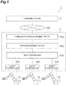
- a control system 1 is a system that controls an actuator of an industrial device (for example, a robot or an NC processing device) installed in a cell of a factory.
- the control system 1 includes a learning system 2 and a factory system 3.
- the factory system 3 is provided in a factory and controls an actuator.
- the factory system 3 has a plurality of nodes X including a control device that controls the actuator.
- the node X is a physical network node, and is an electronic device that performs data communication with another device via a wired or wireless communication line.
- a plurality of nodes X includes a plurality of robot controllers 4 (control devices), a host controller 5 (control device), a data management device 6, and a communication management device 7.
- FIG. 1 shows one host controller 5, the factory system 3 may include a plurality of host controllers 5 provided in a plurality of cells, respectively.
- the factory system 3 may include a plurality of data management devices 6 corresponding to the plurality of host controllers 5, respectively, and may provide a plurality of communication management devices 7 corresponding to the plurality of data management devices 6, respectively. Also, one data management device 6 may be provided for a plurality of host controllers 5, and one communication management device 7 may be provided for a plurality of data management devices 6.
- the plurality of robot controllers 4 are nodes that control a plurality of robots 10 arranged in one cell, for example.
- the robot 10 is, for example, a serial link type vertically articulated robot, and includes an arm A having a plurality (for example six) of joint axes J1, J2, J3, J4, J5, and J6, and a plurality of actuators 11, 12, 13, 14, 15, and 16 for adjusting the position and posture of the distal end of the arm A by driving the respective joint axes J1, J2, J3, J4, J5, and J6.
- each of the actuators 11, 12, 13, 14, 15, and 16 includes a motor 21, a speed reducer 22, and a sensor 23.
- the motor 21 is, for example, a servomotor, and rotates a shaft 21a according to a control command.
- the speed reducer 22 reduces the rotation of the shaft 21a and transmits the rotation to an output shaft 22a.
- the sensor 23 outputs a signal associated with the rotational position and rotational speed of the shaft 21a.
- the sensor 23 is a rotary encoder, and outputs a pulse signal having a frequency proportional to the rotational speed of the shaft 21a.
- the robot controller 4 outputs to the actuators 11, 12, 13, 14, 15, and 16 driving power for bringing the position and posture of the distal end of the arm A closer to the target position and posture.
- the host controller 5 (for example, a programmable logic controller) is a node that outputs the target position and the target posture to each of the plurality of robot controllers 4.
- the data management device 6 is a node that is connected to the host controller 5 and manages data associated with the actuators 11, 12, 13, 14, 15, and 16 of each robot 10.
- the communication management device 7 (readable data construction device) is the node that is connected to the learning system 2 via a network NW such as the Internet, and that manages data communication between the learning system 2 and the factory system 3 according to a predetermined standard (for example, OPC UA).
- the robot controllers 4, the host controller 5, and the data management device 6 are isolated from the network NW (the network between the learning system 2 and the factory system 3) by the communication management device 7.
- the learning system 2 extracts, via the network NW, information for machine learning associated with actuators 11-16 from factory system 3, and generates an estimation model of the condition of the actuators 11, 12, 13, 14, 15, and 16 by machine learning using the information.
- the condition of the actuators 11, 12, 13, 14, 15, and 16 is different types of information from the condition detected by sensing.
- An example of the condition of the actuators 11, 12, 13, 14, 15, and 16 is the iron powder concentration of the grease of the speed reducer 22.
- the conditions of the actuators 11, 12, 13, 14, 15, and 16 include the condition of the objects to be driven by the actuators 11, 12, 13, 14, 15, and 16 in addition to the condition of the actuators 11, 12, 13, 14, 15, and 16 themselves.
- the learning system 2 may be located in the area belonging to the operating entity of the factory system 3, or may be located in an area belonging to another entity.
- the configurations of the learning system 2 and the factory system 3 will be described in detail while appropriately exemplifying the configuration in which the learning system 2 generates the estimation model of the iron powder concentration, and the factory system 3 derives the recommended time for maintenance of the actuators 11, 12, 13, 14, 15, and 16 based on the estimation model.
- the learning system 2 includes, as a functional configuration (hereinafter, referred to as "functional module"), an information extraction unit 111, an information storage unit 112, a model generation unit 113, a model storage 114 (second model storage), a model evaluation unit 115, a display data generation unit 116, an update information transmission unit 117, and a model output unit 118.
- the information extraction unit 111 extracts information for machine learning associated with the actuators 11, 12, 13, 14, 15, and 16 from data (described later) constructed by the communication management device 7 of the factory system 3. For example, the information extraction unit 111 extracts speed data associated with the rotational speed of the speed reducer 22, torque data associated with the torque acting on the speed reducer 22, and concentration data indicating the iron powder concentration of the grease of the speed reducer 22. More specifically, the information extraction unit 111 extracts information (hereinafter, referred to as "learning data”) which is a set of the concentration data, and speed data and torque data for a certain period corresponding to the acquisition time of the concentration data. The information storage unit 112 stores the learning data extracted by the information extraction unit 111.
- learning data information
- the model generation unit 113 generates the estimation model by machine learning using the information stored in the information storage unit 112.
- the estimation model is a program that outputs an estimation result of unknown condition of the actuators 11, 12, 13, 14, 15, and 16 according to the input of known condition of the actuators 11, 12, 13, 14, 15, and 16.
- the estimation model outputs a predicted value of the concentration data (hereinafter, referred to as "predicted concentration data") according to the input of the speed data and the torque data.
- the estimation model is a neural network connecting an input vector including the speed data and the torque data and an output vector including the concentration data.
- Model generation unit 113 uses a combination of the speed data and the torque data for a certain period included in the learning data and the concentration data included in the learning data as teacher data, and for example, tunes the parameters of the estimation model (for example, weighting parameters of the nodes of the neural network) by machine learning processing such as deep learning.
- the estimation model is not necessarily limited to the neural network, and may be any program as long as a desired estimation result can be output according to a predetermined input.
- the estimation model may be a function that returns a numerical value according to an input of an argument.
- the model storage 114 stores the estimation model generated by the model generation unit 113.
- the model storage 114 may be configured to store a plurality of estimation models.
- the model evaluation unit 115 evaluates the estimation accuracy of each estimation model based on information stored in the information storage unit 112 and the estimation result of the conditions of actuators 11, 12, 13, 14, 15, and 16 using a plurality of estimation models.
- a model evaluation unit 115 has the evaluation data derivation unit 121 and the accuracy evaluation unit 122 as more subdivided functional modules.
- the evaluation data derivation unit 121 derives data for evaluation by inputting part of the information stored in the information storage unit 112 to one of estimation models (hereinafter, referred to as "evaluation target model"). For example, the evaluation data derivation unit 121 derives the predicted concentration data by inputting the speed data and the torque data of one of the learning data (hereinafter, referred to as “sample data”) stored in the information storage unit 112 to the estimation model.
- the accuracy evaluation unit 122 evaluates the estimation accuracy of the evaluation target model by comparing data derived by the evaluation data derivation unit 121 with the information of the condition of the actuators 11, 12, 13, 14, 15, and 16 included in the information stored in the information storage unit 112. For example, the accuracy evaluation unit 122 evaluates the estimation accuracy of the evaluation target model by comparing the predicted concentration data derived by the evaluation data derivation unit 121 and the concentration data included in the sample data (hereinafter, referred to as "measured concentration data"). Evaluation of the estimation accuracy includes quantifying the alienation of the predicted concentration data from the measured concentration data by a difference or a ratio. The accuracy evaluation unit 122 stores the evaluation result of the estimation accuracy of the evaluation target model in the model storage 114.
- the display data generation unit 116 generates data for displaying identification information of a plurality of estimation models and the evaluation result of the estimation accuracy of the plurality of estimation models.
- the data is not necessarily limited to image data, and may be any data as long as the above-described estimation accuracy can be displayed.
- the data may be text data.
- the update information transmission unit 117 transmits information of a plurality of estimation models including the estimation model to one of the nodes X of the factory system 3.
- the information of the estimation model includes the evaluation result of the estimation accuracy by the accuracy evaluation unit 122.
- the update information transmission unit 117 transmits an e-mail displaying information of a plurality of estimation models to a portable terminal of an administrator of the factory system 3.
- the model output unit 118 receives designation of the type of the estimation model from one of the nodes X of the factory system 3 (for example, the communication management device 7), and transmits the data of the estimation model according to the designation to the one node X.
- the robot controller 4 includes a position control unit 211, a speed control unit 212, and a torque control unit 213 as functional modules.
- the position control unit 211 generates a speed command value to make the current rotation angle of the actuators 11, 12, 13, 14, 15, and 16 (hereinafter, referred to as "current angle") closer to the target rotation angle (hereinafter, referred to as "target angle").
- the position control unit 211 performs a proportional operation, a proportional/integral operation, or a proportional/integral/differential operation on a deviation between the target angle and the current angle (hereinafter, referred to as "angle deviation") to generate the speed command value.
- the position control unit 211 derives the target angles of the actuators 11, 12, 13, 14, 15, and 16 according to the target position and the target posture of the distal end of the arm A acquired from the host controller 5. Further, the position control unit 211 derives the current angle based on the feedback information from the sensor 23. For example, the position control unit 211 derives the current angle by counting the pulse signals output from the sensor 23. The position control unit 211 transmits history data in which the current time is associated with the target angle and the current angle to the host controller 5.
- the speed control unit 212 generates a torque command value to make the current rotational speed of the actuators 11, 12, 13, 14, 15, and 16 (hereinafter, referred to as "current speed") closer to the speed command value generated by the position control unit 211.
- the speed control unit 212 performs a proportional operation, a proportional/integral operation, or a proportional/integral/differential operation on a deviation between the speed command value and the current speed (hereinafter, referred to as a "speed deviation") to generate a torque command value.
- the speed control unit 212 derives the current speed based on the feedback information from the sensor 23.
- the speed control unit 212 derives the current speed based on the frequency of the pulse signal output from the sensor 23.
- the speed control unit 212 transmits history data in which the current time is associated with the speed command value and the current speed to the host controller 5.
- the torque control unit 213 outputs a drive current to the motor 21 so that the motor 21 generates a torque according to the torque command value generated by the speed control unit 212.
- the torque control unit 213 transmits history data in which the current time is associated with the torque command value and the drive current to the host controller 5.
- the backlash causes the respective parts of the speed reducer 22 and the robot 10 to vibrate.
- the inertial force generated in this vibration becomes a disturbance, and the above-described position deviation and speed deviation fluctuate.
- the speed command value and the torque command value also fluctuate. That is, the fluctuation components of the speed command value and the torque command value include a fluctuation component caused by backlash.
- the host controller 5 includes an operation program storage 311, a command output unit 312, and a control data storage 313 as functional modules.
- the operation program storage 311 stores an operation program for causing each robot 10 to perform a predetermined operation.
- the operation program includes a target position and a target posture (a target position and a target posture at the distal end of the arm A) arranged in time series.
- the command output unit 312 sequentially outputs the operation program of the operation program storage 311 to the robot controller 4.
- the control data storage 313 stores the history data transmitted from the position control unit 211, the speed control unit 212, and the torque control unit 213 of the robot controller 4.
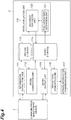
- the data management device 6 includes, a functional module, a model request unit 411, a model storage 412 (first model storage), an interface storage 413, a data acquisition unit 415, a data storage 416, an estimation unit 417, a prediction data storage unit 418, a model construction unit 419, a model storage 420, recommended time derivation units 421, 422, a prediction formula correction unit 423, a prediction formula storage 424, a display data generation unit 425, and a display unit 426.
- a functional module includes, a functional module, a model request unit 411, a model storage 412 (first model storage), an interface storage 413, a data acquisition unit 415, a data storage 416, an estimation unit 417, a prediction data storage unit 418, a model construction unit 419, a model storage 420, recommended time derivation units 421, 422, a prediction formula correction unit 423, a prediction formula storage 424, a display data generation unit 425, and a display unit 426.
- the model request unit 411 requests the model output unit 118 of the learning system 2 to transmit the data of the estimation model (hereinafter, referred to as "model data").
- model data may be the estimation model itself, or may be a parameter for specifying the estimation model (for example, a weighting parameter of a neural network node).
- the model request unit 411 may be configured to designate the type of the estimation model when transmitting the model data.
- the model storage 412 stores the estimation model generated by the learning system 2. Since the model storage 412 only needs to be provided in one of the nodes X, it may be provided in the robot controller 4, the host controller 5, or the communication management device 7 instead of the data management device 6.
- the interface storage 413 stores an interface program for accessing data in the host controller 5.
- the interface storage 413 stores an interface program for accessing the history data of the control data storage 313.
- the interface program is, for example, an application programming interface (API). Since the interface storage 413 may be provided in the node X isolated from the network NW by the communication management device 7, it may be provided in the robot controller 4 or the host controller 5 instead the communication management device 7.
- API application programming interface
- the data acquisition unit 415 repeatedly acquires the speed data and the torque data and saves the data in the data storage 416 in association with the acquisition time. For example, the data acquisition unit 415 reads the speed command value by the interface program of the interface storage 413, and acquires this as the speed data. Further, the data acquisition unit 415 reads the torque command value by the interface program of the interface storage 413, and acquires this as torque data. By using the interface program to acquire the speed data and torque data, unnecessary access to another storage area of the control data storage 313 (for example, the operation program storage 311) can be prevented. Note that the data acquisition unit 415 may acquire the current speed as speed data and may acquire the drive current as torque data.
- the data acquisition unit 415 acquires the measured concentration data when it is input, and stores it in the data storage 416 in association with the acquisition time.
- the measured concentration data is, for example, a concentration of iron powder measured by collecting grease from the speed reducer 22.
- the acquisition time of the measured concentration data may be the time at which the operator collected the grease, or may be the time at which the data acquisition unit 415 acquired the measured concentration data.
- the estimation unit 417 estimates the condition of the actuators 11, 12, 13, 14, 15, and 16 based on the estimation model stored in the model storage 412. Since the estimation unit 417 only needs to be provided in any of the nodes X, it may be provided in the robot controller 4, the host controller 5, or the communication management device 7 instead of the data management device 6. For example, the estimation unit 417 estimates the deterioration level of the actuators 11, 12, 13, 14, 15, and 16. For example, the estimation unit 417 estimates the predicted concentration data based on the estimation model. Specifically, the estimation unit 417 acquires speed data and torque data (hereinafter, referred to as an "input data set") for a certain period from the data storage 416, and inputs the input data to the estimation model stored in the model storage 412 to derive the predicted concentration data.
- input data set speed data and torque data
- the estimation unit 417 Each time the estimation unit 417 derives the predicted concentration data, it stores the predicted concentration data in the prediction data storage unit 418 in association with the prediction target time.
- the prediction target time may be the derivation completion time of the predicted concentration data, or may be a time that is a predetermined time before the derivation completion time.
- the model construction unit 419 constructs a rising prediction model including a future chronological transition of the predicted concentration data based on the chronological transition of the predicted concentration data. For example, the model construction unit 419 determines whether the predetermined number of new predicted concentration data (predicted concentration data that is not used in the construction of the rising prediction model in the model construction unit 419) is stored in the prediction data storage unit 418. When it is determined that the predetermined number of new predicted concentration data has been stored, the model construction unit 419 constructs the rising prediction model of concentration data based on the predetermined number of predicted concentration data.
- the rising prediction model is, for example, a function indicating the relationship between the total drive time of the speed reducer 22 and the predicted concentration data.
- the model construction unit 419 constructs the rising prediction model by performing polynomial interpolation or the like on the predetermined number of predicted concentration data.
- the model construction unit 419 stores the constructed rising prediction model in the model storage 420.
- the recommended time derivation unit 421 derives a recommended time for maintenance of the speed reducer 22 based on the rising prediction model of the model storage 420.
- the recommended time for maintenance of the speed reducer 22 is, for example, a time at which the iron powder concentration of the grease of the speed reducer 22 reaches a predetermined threshold value.
- the threshold value is set in advance based on past results.
- the recommended time derivation unit 421 derives the total drive time until the predicted concentration data reaches a predetermined threshold value as a recommended time for maintenance of the speed reducer 22 (hereinafter, referred to as a "first recommended time") based on the rising prediction model.
- the recommended time derivation unit 421 may derive, as the first recommended time, the total drive time until when the increasing speed of the grease iron powder concentration of the speed reducer 22 reaches a predetermined threshold value.
- the prediction formula storage 424 stores a prediction formula for deriving a recommended time for maintenance of the speed reducer 22.
- the prediction formula is a mathematical expression indicating the relationship between the rotational speed of the speed reducer 22 and the torque acting on the speed reducer 22, and the recommended time for maintenance of the speed reducer 22.
- the specific example of the prediction formula includes a life prediction formula of the bearing of the speed reducer 22.
- the prediction formula correction unit 423 corrects the prediction formula to make the recommended time for maintenance of the speed reducer 22 derived based on the prediction formula (hereinafter, referred to as "second recommended time") closer to the first recommended time derived by the recommended time derivation unit 421.
- the prediction formula correction unit 423 corrects the value of the correction coefficient A to make the second recommended time derived based on the above formula (1) closer to the first recommended time.
- the recommended time derivation unit 422 derives the second recommended time based on the set values of the rotational speed of the speed reducer 22 and the torque acting on the speed reducer 22, and the prediction formula corrected by the prediction formula correction unit 423.
- the set values are input by, for example, an operator.
- the display data generation unit 425 generates image data for displaying at least one of the first recommended time derived by the recommended time derivation unit 421 and the second recommended time derived by the recommended time derivation unit 422.
- the display unit 426 displays an image including at least one of the first recommended time and the second recommended time based on the image data generated by the display data generation unit 425.
- the communication management device 7 includes, as a functional module, a data acquisition unit 511 (acquisition unit), a data construction unit 512, a read data storage 513, an information extraction unit 514, a model acquisition unit 515, and a communication restriction unit 516.
- the data acquisition unit 511 acquires information for machine learning associated with the actuators 11, 12, 13, 14, 15, and 16 of the plurality of robots 10 from one of the nodes X other than the data acquisition unit 511. For example, the data acquisition unit 511 acquires, from the data storage 416 of the data management device 6, the information for machine learning read out from the control data storage 313 in the host controller 5 by the interface program stored in the interface storage 413.
- the read data storage 513 stores the data in a state where it is readable from the learning system 2.
- the data construction unit 512 constructs data including the information acquired by the data acquisition unit 511, and makes the data readable from the learning system 2.
- the data construction unit 512 constructs data in which the information acquired by the data acquisition unit 511 is structured by classification information including identification information of the actuators 11, 12, 13, 14, 15, and 16.
- Other classification information of the identification information of the actuators 11, 12, 13, 14, 15, and 16 includes the identification information of the factory cell, the identification information of the robot, the type of information, and the like. Specific examples of the type of information include the speed data, the torque data, the concentration data, and the like.
- the data construction unit 512 constructs the data having a tree-like structure sequentially branched by cell identification information, robot identification information, actuator identification information, and information type, and stores the data in the read data storage 513.
- the information extraction unit 111 of the learning system 2 described above extracts the information for machine learning from the data by designating the classification information.
- the information extraction unit 514 extracts information corresponding to the designation of the classification information by the information extraction unit 111 of the learning system 2 from the data of the read data storage 513.
- the model acquisition unit 515 acquires the model data transmitted from the model output unit 118 in response to a request from the model request unit 411 of the data management device 6, and stores the model data in the model storage 412.
- the model acquisition unit 515 saves the acquired model data over the model storage 412.
- the model data is a parameter of the estimation model
- the parameter of the estimation model stored in the model storage 412 is changed to the acquired parameter.
- the communication restriction unit 516 is interposed between the information extraction unit 514, the model acquisition unit 515, and the model request unit 411 on the factory system 3 side, and the information extraction unit 111 and the model output unit 118 on the learning system 2 side, and restrict communication between them. For example, when the communication restriction unit 516 receives data different from the data according to the request from the model request unit 411 from the model output unit 118, it blocks the entry of the data, and prevents the data from being acquired by the model acquisition unit 515. Further, when acquiring, from the information extraction unit 514, data that does not correspond to the designation of the classification information from the information extraction unit 111, the communication restriction unit 516 blocks the leakage of the data, and prevents the data from being transmitted to the information extraction unit 111.
- the learning system 2 includes circuitry 190.
- the circuitry 190 includes at least one processor 191, a memory 192, a storage 193, and a network adapter 194.
- the storage 193 is a computer readable non-volatile storage medium (for example, hard disk or flash memory).
- the storage 193 includes a storage area for a program for configuring respective functional modules of the learning system 2, and a storage area allocated to the information storage unit 112 and the model storage 114.
- the memory 192 temporarily stores the program loaded from the storage 193, the calculation result by the processor 191, and the like.
- the processor 191 executes the program in cooperation with the memory 192, and constitutes respective functional modules of the learning system 2.
- the network adapter 194 performs network communication via the network NW in accordance with a command from the processor 191.
- the robot controller 4 includes circuitry 290.
- the circuitry 290 includes the at least one processor 291, a memory 292, a storage 293, a driver 294, an input/output port 295, and a communication port 296.
- the storage 293 is a computer readable non-volatile storage medium (for example, hard disk or flash memory).
- the storage 293 stores a program for configuring respective functional modules of the robot controller 4.
- the memory 292 temporarily stores the program loaded from the storage 293, the calculation result by the processor 291, and the like.
- the processor 291 executes the program in cooperation with the memory 292, and constitutes respective functional modules of the robot controller 4.
- the driver 294 outputs driving power to the motor 21 of the actuators 11, 12, 13, 14, 15, and 16 in accordance with a command from the processor 291.
- the input/output port 295 acquires a signal from the sensor 23 in accordance with a command from the processor 291.
- the communication port 296 performs network communication with the host controller 5 in accordance with a command
- the host controller 5 has circuitry 390.
- the circuitry 390 includes at least one processor 391, a memory 392, a storage 393, and a communication port 394.
- the storage 393 is a computer readable non-volatile storage medium (for example, hard disk or flash memory).
- the storage 393 includes a storage area of a program for configuring respective functional modules of the host controller 5, and a storage area allocated to the operation program storage 311 and the control data storage 313.
- the memory 392 temporarily stores the program loaded from the storage 393, the calculation result by the processor 391, and the like.
- the processor 391 executes the program in cooperation with the memory 392, and constitutes respective functional modules of the host controller 5.
- the communication port 394 performs network communication with the robot controller 4 and the data management device 6 in accordance with a command from a processor 391.
- the data management device 6 has circuitry 490.
- the circuitry 490 includes the at least one processor 491, a memory 492, a storage 493, a communication port 494, a monitor 495, and an input device 496.
- the storage 493 is a computer readable non-volatile storage medium (for example, hard disk or flash memory).
- the storage 493 includes a storage area of a program for configuring respective functional modules of the data management device 6, and storage areas allocated to the model storage 412, the interface storage 413, the data storage 416, the prediction data storage unit 418, the model storage 420 and the prediction formula storage 424.
- the memory 492 temporarily stores the program loaded from the storage 493, the calculation result by the processor 491, and the like.
- the processor 491 executes the program in cooperation with the memory 492, and constitutes respective functional modules of the data management device 6.
- the communication port 494 performs network communication with the host controller 5 and the communication management device 7 in accordance with a command from a processor 491.
- the monitor 495 is an image display device such as a liquid crystal monitor, and is used as the display unit 426 and the like, for example.
- the input device 496 is, for example, an information input device such as a keypad, and is used for acquiring a set value by the recommended time derivation unit 422.
- the monitor 495 and the input device 496 may be integrated as a so-called touch panel.
- the communication management device 7 has circuitry 590.
- the circuitry 590 includes at least one processor 591, a memory 592, a storage 593, a communication port 594, and a network adapter 595.
- the storage 593 is a computer readable non-volatile storage medium (for example, hard disk or flash memory).
- the storage 593 includes a storage area for configuring the respective functional modules of the communication management device 7, and a storage area allocated to the read data storage 513.
- the memory 592 temporarily stores the program loaded from the storage 593, the calculation result by the processor 591, and the like.
- the processor 591 executes the program in cooperation with the memory 592, and constitutes respective functional modules of the communication management device 7.
- the communication port 594 performs network communication with the data management device 6 in accordance with a command from the processor 591.
- the network adapter 595 performs network communication via the network NW in accordance with a command from the processor 591.
- step S01 the information extraction unit 111 waits for a new data to be stored in the read data storage 513. Whether the new data has been stored in the read data storage 513 can be validated by an inquiry to the information extraction unit 514 or a notification from the information extraction unit 514.
- step S02 the information extraction unit 111 transmits the designation of the classification information to the communication restriction unit 516.
- step S03 the information extraction unit 111 acquires the data extracted from the read data storage 513 according to the designation in step S02 from the communication restriction unit 516 and stores it in the information storage unit 112.
- step S04 the information extraction unit 111 validates whether all data constituting the learning data has been acquired. When it is determined in step S04 that unacquired data remains, the learning system 2 returns the process to step S02. Thereafter, the data extraction by designating the classification information is repeated until acquisition of all the data constituting the learning data is completed.
- step S05 the model generation unit 113 validates whether the number of learning data required for machine learning has been stored in the information storage unit 112.
- step S05 the number of learning data required for machine learning has not been stored
- the learning system 2 returns the process to step S01. Thereafter, the accumulation of the learning data is repeated until the required number of learning data for the machine learning is stored.
- step S05 When it is determined in step S05 that the number of learning data required for machine learning has been stored in the information storage unit 112, the learning system 2 executes steps S06 and S07 in order.
- step S06 the model generation unit 113 generates the estimation model by machine learning based on the learning data stored in the information storage unit 112.
- step S07 the model generation unit 113 stores the generated estimation model in the model storage 114. Thus, the procedure for generating the estimation model is completed.
- the learning system 2 repeatedly executes the above procedure.
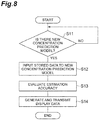
- the learning system 2 sequentially executes steps S11, S12, S13, and S14.
- step S11 the model evaluation unit 115 waits for a new estimation model to be stored in the model storage 114.
- step S12 the model evaluation unit 115 selects one of the learning data as sample data, and inputs the speed data and the torque data included in the sample data to an evaluation target model (an estimation model newly stored in the model storage 114) to derive the predicted concentration data.
- the model evaluation unit 115 compares the predicted concentration data derived in step S12 with the measured concentration data included in the sample data, evaluates the estimation accuracy of the estimation models, and stores the evaluation result in the model storage 114.
- step S14 display data generation unit 116 generate data for displaying identification information of a plurality of estimation models and the evaluation result of the estimation accuracy of the a plurality of types estimation models, and the update information transmission unit 117 transmits the data to one of the nodes X of the factory system 3.
- the procedure for evaluating the estimation model is completed.
- the learning system 2 repeatedly executes the above procedure.
- the learning system 2 sequentially executes steps S21, S22, and S23.
- step S21 the model output unit 118 waits for a transmission request for the estimation model to be transmitted from the communication restriction unit 516.
- step S22 the model output unit 118 acquires from the communication restriction unit 516 the designation of the type of the estimation model to be transmitted.
- step S23 the model output unit 118 transmits the data of the estimation model designated in step S22 to the communication restriction unit 516.
- the learning system 2 repeatedly executes the above procedure.
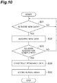
- the communication management device 7 first executes steps S31, S32, and S33 in order.
- step S31 the data acquisition unit 511 waits for new data to be added to the data storage 416.
- step S32 the data acquisition unit 511 acquires new data added to the data storage 416.
- step S33 the data acquisition unit 511 validates whether acquisition of new data has been completed for the actuators 11, 12, 13, 14, 15, and 16 of all the robots 10.
- step S33 when it is determined that actuators 11, 12, 13, 14, 15, and 16 for which new data has not been acquired remain, the communication management device 7 returns the process to step S31. Thereafter, the acquisition of new data is repeated until the acquisition of new data for the actuators 11, 12, 13, 14, 15, and 16 of all the robots 10 is completed.
- step S33 when it is determined that acquisition of new data has been completed for the actuators 11, 12, 13, 14, 15, and 16 of all the robots 10, the communication management device 7 executes steps S34 and S35 in order.
- step S34 the data construction unit 512 constructs the data using the new data.
- step S35 the data construction unit 512 stores the data constructed in step S34 in the read data storage 513.
- the data construction unit 512 saves the data constructed in step S34 over the read data storage 513. This completes the data construction procedure.
- the communication management device 7 repeatedly executes the above procedure.
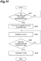
- the communication management device 7 first executes steps S41, S42, S43, and S44 in order.
- step S41 the communication restriction unit 516 waits for a reception of a data transmission request from the information extraction unit 111.
- the communication restriction unit 516 receives the classification designation of the data to be transmitted.
- step S43 the information extraction unit 514 extracts data corresponding to the classification designation received in step S42 from the data of the read data storage 513, and outputs it to the communication restriction unit 516.
- the communication restriction unit 516 validates whether the data acquired from the information extraction unit 514 matches the classification designation.
- step S44 when it is determined that the data acquired from the information extraction unit 514 does not match the classification designation, the communication management device 7 returns the process to step S43. Thereafter, data extraction and data check are repeated until data matching the classification designation is extracted.
- step S45 the communication restriction unit 516 transmits to the information extraction unit 111 the data determined to match the classification designation. This completes the data transmission procedure.
- the communication management device 7 repeatedly executes the above procedure.
- the communication management device 7 first executes steps S51, S52, and S53 in order.
- step S51 the communication restriction unit 516 waits a request for data of the estimation model from the model request unit 411.
- step S52 the communication restriction unit 516 transmits a transmission request for the estimation model to the model output unit 118.
- step S53 the communication restriction unit 516 acquires designation of the type of the estimation model from the model request unit 411 and transmits the designation to the model output unit 118.
- step S54 communication restriction unit 516 waits for a reception of data from the model output unit 118.
- step S55 the communication restriction unit 516 validates whether the data received from the model output unit 118 is the data of the estimation model designated by the model request unit 411. For example, the communication restriction unit 516 validates whether the received data is the data of the designated estimation model based on the identification information included in the data received from the model output unit 118.
- step S55 the communication management device 7 returns the process to step S54. Thereafter, data reception and data check are repeated until the data of the designated estimation model is received.
- step S55 When it is determined in step S55 that the received data is the data of the designated estimation model, the communication management device 7 executes steps S56 and S57 in order.
- step S56 the model acquisition unit 515 acquires the data of the estimation model received by the communication restriction unit 516.
- step S57 the model acquisition unit 515 stores the data of the estimation model acquired in step S56 in the model storage 412 of the data management device 6. Thus, the procedure for acquiring the data of the estimation model is completed.
- the communication management device 7 repeatedly executes the above procedure.
- the data management device 6 first executes steps S61, S62, and S63 in order.
- step S61 the estimation unit 417 waits for the new input data (input data not used for deriving the predicted concentration data) to be stored in the data storage 416.
- step S62 the estimation unit 417 inputs the new input data to the estimation model of the model storage 412, and derives the predicted concentration data.
- step S63 the model construction unit 419 determines whether the predetermined number of new predicted concentration data (unused predicted concentration data in the model construction unit 419) has been stored in the prediction data storage unit 418.
- the data management device 6 When it is determined that the number of stored new predicted concentration data does not reach the predetermined number, the data management device 6 returns the process to step S61. Thereafter, the derivation and storage of the predicted concentration data are repeated until it is determined that the predetermined number of new predicted concentration data has been stored in the prediction data storage unit 418.
- step S63 when it is determined that the predetermined number of new predicted concentration data has been stored in the prediction data storage unit 418, the data management device 6 executes step S64.
- step S64 the model construction unit 419 constructs a rising prediction model of the predicted concentration data based on the predetermined number of new predicted concentration data.
- step S65 the recommended time derivation unit 421 derives the first recommended time (recommended time for maintenance of the speed reducer 22 based on the estimation model) based on the rising prediction model.
- step S66 the display data generation unit 425 generates image data for displaying the first recommended time, and the display unit 426 displays an image including the first recommended time based on the image data.
- step S67 the recommended time derivation unit 422 derives the second recommended time (recommended time for maintenance of the speed reducer 22 based on the prediction formula) based on the prediction formula.
- step S68 the prediction formula correction unit 423 corrects the prediction formula to make the second recommended time closer to the first recommended time. For example, the prediction formula correction unit 423 corrects the value of the correction coefficient A by multiplying the ratio between the second recommended time calculated in step S67 and the first recommended time calculated in step S65.
- the procedure for deriving the recommended time for maintenance based on the estimation model is completed. The data management device 6 repeatedly executes the above procedure.
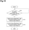
- step S71 the recommended time derivation unit 422 waits for input of the set values of the rotational speed and the torque of the speed reducer 22.
- step S72 the recommended time derivation unit 422 derives the second recommended time based on the input set value and the prediction formula corrected by the prediction formula correction unit 423. For example, the recommended time derivation unit 422 derives the second recommended time based on the above formula (1).
- step S73 the display data generation unit 425 generates image data for displaying the second recommended time, and the display unit 426 displays an image including the second recommended time based on the image data.
- the display data generation unit 425 may generate image data for displaying both the first recommended time and the second recommended time. Thus, the procedure for deriving the recommended time for maintenance based on the prediction formula is completed.
- the data management device 6 repeatedly executes the above-described procedure for deriving the recommended time for maintenance.
- control system 1 includes the factory system 3 configured to control actuators 11, 12, 13, 14, 15, and 16, and the learning system 2 configured to extract information for machine learning associated with actuators 11, 12, 13, 14, 15, and 16 from factory system 3 via network NW and to generate an estimation model of the condition of the actuators 11, 12, 13, 14, 15, and 16 by machine learning using the information.
- the factory system 3 includes a plurality of nodes X including a robot controller 4 controlling the actuators 11, 12, 13, 14, 15, and 16 and the host controller 5, and the communication management device 7 connected to the learning system 2 via the network NW.
- the communication management device 7 includes the data acquisition unit 511 that acquires information for machine learning from one of the nodes X other than the communication management device 7, and the data construction unit 512 that constructs a data including the information acquired by the data acquisition unit 511 and makes the data readable from the learning system 2.
- control system 1 it is possible to provide information for machine learning from the factory system 3 to the learning system 2 without network access to the robot controller 4 and the host controller 5. For this reason, it is possible to achieve both the continued reliability of the robot controller 4 and the host controller 5 and the efficiency of collecting information for machine learning. Therefore, it is effective in expanding the use of machine learning in the factory system 3.
- the data acquisition unit 511 may acquire information for machine learning read out from the host controller 5 by an interface program for accessing data in the host controller 5, and the interface program may be stored in the interface storage 413 provided in any of the nodes X, among the nodes X, isolated from the network NW by the communication management device 7. In this case, it is possible to suppress accidental access to a storage area that is different from the area configured to store the information by acquiring the information for machine learning read out by the interface program. Also, by arranging the interface program in the interface storage 413 of the node X isolated from the network NW by the communication management device 7, it is possible to restrict network access to the host controller 5 more strictly, and more securely maintain the reliability of the host controller 5.
- the plurality of nodes X may include an additional node X other than the communication management device 7, the robot controller 4 and the host controller 5, and the additional node X may include the interface storage 413.
- the data acquisition unit 511 may acquire the information for machine learning associated with a plurality of the actuators 11, 12, 13, 14, 15, and 16, wherein the data construction unit 512 may construct the data obtained by structuring information acquired by the data acquisition unit 511 by classification information including identification information of the actuators 11, 12, 13, 14, 15, and 16, and the learning system 2 may include the information extraction unit 111 configured to extract the information for machine learning from the data by designating the classification information, the information storage unit 112 configured to store the information for machine learning extracted by the information extraction unit 111, and the model generation unit 113 configured to generate the estimation model by machine learning using information stored in the information storage unit 112. In this case, the efficiency of collecting information for machine learning can be further improved.
- One of the plurality of nodes X may include the model storage 412 configured to store data of an estimation model generated by the learning system 2, and one of the plurality of nodes X may include the estimation unit 417 configured to estimate the condition of the actuators 11, 12, 13, 14, 15, and 16 based on an estimation model stored in the model storage 412.
- the frequency of data transmission from the learning system 2 to the factory system 3 decreases, compared to when applying the estimation model arranged in the learning system 2 to the estimation of the conditions of the actuators 11, 12, 13, 14, 15, and 16. Therefore, the reliability of the robot controller 4 and the host controller 5 can be more securely maintained.
- the estimation unit 417 may estimate the deterioration level of the actuators 11, 12, 13, 14, 15, and 16.
- One of the nodes X may further include the parameter adjustment unit 314 for adjusting the control parameter of the actuators 11, 12, 13, 14, 15, and 16 based on the estimation result of the conditions of the actuators 11, 12, 13, 14, 15, and 16 by the estimation unit 417.
- the learning system 2 may include the model storage 114 configured to store a plurality of the estimation models generated by the model generation unit 113, the model evaluation unit 115 configured to evaluate an estimation accuracy of each of the estimation models based on information stored in the information storage unit 112 and estimation results of the conditions of the actuators 11, 12, 13, 14, 15, and 16 by the plurality of estimation models, and the display data generation unit 116 configured to generate data for displaying identification information of the plurality of estimation models and an evaluation result of an estimation accuracy of the plurality of estimation models.
- the model storage 114 configured to store a plurality of the estimation models generated by the model generation unit 113
- the model evaluation unit 115 configured to evaluate an estimation accuracy of each of the estimation models based on information stored in the information storage unit 112 and estimation results of the conditions of the actuators 11, 12, 13, 14, 15, and 16 by the plurality of estimation models
- the display data generation unit 116 configured to generate data for displaying identification information of the plurality of estimation models and an evaluation result of an estimation accuracy of the plurality of estimation models.
- the model evaluation unit 115 may include the evaluation data derivation unit 121 configured to input part of information stored in the information storage unit 112 to the estimation models to derive data for evaluation, and the accuracy evaluation unit 122 configured to compare data derived by the evaluation data derivation unit 121 with information of a condition of the actuators 11, 12, 13, 14, 15, and 16 included in information stored in the information storage unit 112 to evaluate an estimation accuracy of the estimation models.
- the estimation model can be quickly evaluated by utilizing existing data for evaluating the estimation model.
- the learning system 2 may include the model output unit 118 configured to receive a designation of a type of the estimation model from one of the nodes X of the factory system 3 and to transmit, to the one of the nodes X, data of the estimation model according to the designation. In this case, a request for selective transmission of the estimation model based on the evaluation result of the estimation model is enabled, and the frequency of data transmission to the factory system 3 can be further reduced.
- the control system 1 includes the factory system 3 configured to control the actuators 11, 12, 13, 14, 15, and 16, and the learning system 2 configured to extract information for machine learning associated with the actuators 11, 12, 13, 14, 15, and 16 from the factory system 3 via the network NW, and to generate an estimation model of a condition of the actuators 11, 12, 13, 14, 15, and 16 by machine learning using the information
- the factory system 3 includes a plurality of nodes X including the robot controllers 4 that are nodes controlling the actuators 11, 12, 13, 14, 15, and 16 and the host controller 5, one of the plurality of nodes X includes the model storage 412 configured to store the estimation model generated by the learning system 2, and one of the plurality of nodes X includes the estimation unit 417 configured to estimate a condition of the actuators 11, 12, 13, 14, 15, and 16 based on the estimation model stored in the model storage 412.
- both long-term machine learning and real-time utilization of the learning result in control can be achieved. Therefore, it is effective in expanding the use of machine learning in the factory system 3.
- One of the plurality of nodes X may include a model request unit 411 configured to request the learning system 2 to transmit data of the estimation model, and one of the plurality of nodes X may include the model acquisition unit 515 configured to acquire the data of the estimation model transmitted according to a request from the model request unit 411.
- the transmission timing of the model data from the learning system 2 to the factory system 3 can be determined on the factory system 3 side, so that the frequency of unexpected data transmission to the factory system 3 can be reduced more reliably.
- Any of the plurality of nodes X may include the communication restriction unit 516 configured to restrict acquisition of data that is different from the data according to a request from the model request unit 411. In this case, the frequency of unexpected data transmission to the factory system 3 can be reduced more reliably.
- any of the nodes X may further include the parameter adjustment unit for adjusting the control parameter of the actuators 11, 12, 13, 14, 15, and 16 based on the estimation result of the conditions of the actuators 11, 12, 13, 14, 15, and 16 by the estimation unit 417.
- the robot controller 4 further includes a parameter storage 214
- the host controller 5 further includes a parameter adjustment unit 314.
- the parameter storage 214 stores various control parameters (for example, a position control gain, a speed control gain, a torque control gain, and the like).
- the position control unit 211, the speed control unit 212, and the torque control unit 213 execute the above-described control according to the control parameters stored in the parameter storage 214.
- the parameter adjustment unit 314 adjusts the control parameters of the actuators 11, 12, 13, 14, 15, and 16 stored in the parameter storage 214 based on the estimation result of the conditions of the actuators 11, 12, 13, 14, 15, and 16 by the estimation unit 417.
- the node configuration of the factory system 3 is not necessarily limited to the configuration described above.
- the factory system 3 only needs to include at least control devices such as the robot controller 4 and the host controller 5, and the communication management device 7.
- at least part of the function of the data management device 6 may be incorporated in the host controller 5, or all functions of the data management device 6 may be incorporated in the host controller 5.
Landscapes
- Engineering & Computer Science (AREA)
- Software Systems (AREA)
- Artificial Intelligence (AREA)
- General Physics & Mathematics (AREA)
- Physics & Mathematics (AREA)
- Evolutionary Computation (AREA)
- Theoretical Computer Science (AREA)
- Medical Informatics (AREA)
- Computer Vision & Pattern Recognition (AREA)
- Automation & Control Theory (AREA)
- Robotics (AREA)
- Mechanical Engineering (AREA)
- Health & Medical Sciences (AREA)
- Data Mining & Analysis (AREA)
- Computing Systems (AREA)
- General Engineering & Computer Science (AREA)
- Mathematical Physics (AREA)
- Computational Linguistics (AREA)
- Power Engineering (AREA)
- Testing And Monitoring For Control Systems (AREA)
- Manipulator (AREA)
- General Factory Administration (AREA)
- Control Of Electric Motors In General (AREA)
- Feedback Control In General (AREA)
Abstract
Description
- The present disclosure relates to a control system, a factory system, learning system, an estimation model generation method, and an actuator state estimation method.
-
Patent Literature 1 discloses an abnormality analysis system including a plurality of production facilities each including one or more detectors, a first network installed in a predetermined area, and an analysis device configured to perform a data analysis based on the detector information acquired via the first network, and generate determination information associated with each abnormality of the plurality of production facilities or abnormality of the production target based on data analysis results. - Patent Literature 1: Japanese Unexamined Patent Publication No.
2017-97839 - An object of the present disclosure is to provide a control system effective for expanding use of machine learning in a factory system configured to control an actuator.
- A control system according to an aspect of the present disclosure includes a factory system configured to control an actuator, and a learning system configured to extract information for machine learning associated with the actuator from the factory system via a network and generate an estimation model of a condition of the actuator by machine learning using the information, wherein the factory system includes a plurality of nodes including a control device controlling the actuator, and a readable data construction device connected to the learning system via the network, and wherein the readable data construction device includes an acquisition unit configured to acquire the information for machine learning from one of the nodes other than the readable data construction device, and a data construction unit configured to construct a data including information acquired by the acquisition unit and make the data readable from the learning system.
- A control system according to another aspect of the present disclosure includes a factory system configured to control an actuator, and a learning system configured to extract information for machine learning associated with the actuator from the factory system via a network and generate an estimation model of a condition of the actuator by machine learning using the information, wherein the factory system includes a plurality of nodes including a control device controlling the actuator, one of the plurality of nodes includes a first model storage configured to store the estimation model generated by the learning system, and one of the plurality of nodes includes an estimation unit configured to estimate a condition of the actuator based on the estimation model stored in the first model storage.
- A control system according to still another aspect of the present disclosure includes a factory system configured to control an actuator, and a learning system configured to extract information for machine learning associated with the actuator from the factory system via a network and generate an estimation model of a condition of the actuator by machine learning using the information, wherein the factory system includes a plurality of nodes including a control device controlling the actuator, one of the plurality of nodes includes a first model storage configured to store the estimation model generated by the learning system, and one of the plurality of nodes includes an estimation unit configured to estimate a condition of the actuator based on the estimation model stored in the first model storage.
- A factory system according to still another aspect of the present disclosure is a factory system connected to a learning system for machine learning via a network. The factory system includes a plurality of nodes including a control device configured to control an actuator, and a readable data construction device connected to the learning system via the network, wherein the readable data construction device includes an acquisition unit configured to acquire the information for machine learning from the control device, and a data construction unit configured to construct a data including information acquired by the acquisition unit and make the data readable from the learning system.
- A factory system according to still another aspect of the present disclosure is a factory system connected to a learning system for machine learning via a network. The factory system includes a plurality of nodes including a control device configured to control an actuator, wherein one of the plurality of nodes includes a first model storage configured to store an estimation model of a condition of the actuator generated by the learning system, and one of the plurality of nodes includes an estimation unit configured to estimate a condition of the actuator based on the estimation model stored in the first model storage.
- A learning system according to still another aspect of the present disclosure includes an information extraction unit configured to acquire information for machine learning associated with a plurality of actuators from a control device of the plurality of actuators, where the information extraction unit is connected via a network to a readable data construction device that constructs a data obtained by structuring acquired information by classification information including identification information of the actuators, where the information extraction unit is configured to extract the information for machine learning from the data by designating the classification information, an information storage unit configured to store the information for machine learning extracted by the information extraction unit, and a model generation unit configured to generate an estimation model of a condition of the actuators by machine learning using information stored in the information storage unit.
- A generation method of an estimation model according to still another aspect of the present disclosure includes acquiring information for machine learning associated with a plurality of actuators from a control device of the plurality of actuators, by a learning system connected via a network to a readable data construction device that constructs a data obtained by structuring acquired information by classification information including identification information of the actuators, designating the classification information, and extracting the information for machine learning from the data set, storing the acquired information for machine learning in the learning system, and by machine learning using the information for machine learning stored in the learning system, generating an estimation model of a condition of the actuators by the learning system.
- An estimation method of a condition of an actuator according to still another aspect of the present disclosure includes, by a readable data construction device of a factory system including a control device configured to control the actuator and the readable data construction device connected to a learning system via a network, acquiring information for machine learning associated with the actuator from the control device, constructing a data containing the acquired information, and making the data readable from the learning system, and estimating a condition of the actuator by the factory system based on an estimation model of a condition of the actuator generated by the learning system by machine learning using information extracted from the data set.
- An estimation method of a condition of an actuator according to still another aspect of the present disclosure includes acquiring an estimation model of a condition of the actuator generated by machine learning in a learning system from the learning system via a network to store the estimation model in a factory system, and estimating a condition of the actuator by the factory system based on the estimation model stored in the factory system.
- According to the present disclosure, it is possible to provide a control system that is effective for expanding use of machine learning in a factory system configured to control an actuator.
-
-
FIG. 1 is a schematic view illustrating an overall configuration of a control system. -
FIG. 2 is a schematic view illustrating the schematic configuration of a robot. -
FIG. 3 is a schematic view illustrating the schematic configuration of an actuator. -
FIG. 4 is a block diagram illustrating the configuration of a learning system. -
FIG. 5 is a block diagram illustrating the configuration of a factory system. -
FIG. 6 is a block diagram illustrating the hardware configuration of the robot system. -
FIG. 7 is a flowchart illustrating a procedure for constructing an estimation model. -
FIG. 8 is a flowchart illustrating a procedure for evaluating of an estimation model. -
FIG. 9 is a flowchart illustrating an output procedure of an estimation model. -
FIG. 10 is a flowchart illustrating a procedure for constructing a data set. -
FIG. 11 is a flowchart illustrating a procedure for transmitting data for machine learning. -
FIG. 12 is a flowchart illustrating a procedure for acquiring data of an estimation model. -
FIG. 13 is a flowchart illustrating a procedure for deriving a recommended time for maintenance based on an estimation model. -
FIG. 14 is a flowchart illustrating a procedure for deriving a recommended time for maintenance based on a prediction formula. -
FIG. 15 is a block diagram illustrating a modification of the configuration of the factory system. - Hereinafter, embodiments will be described in detail with reference to the drawings. Note that in the description, same elements or elements having the same function are denoted by the same reference numerals, and duplicate explanation is omitted.
- A
control system 1 according to the present embodiment is a system that controls an actuator of an industrial device (for example, a robot or an NC processing device) installed in a cell of a factory. As shown inFIG. 1 , thecontrol system 1 includes alearning system 2 and afactory system 3. Thefactory system 3 is provided in a factory and controls an actuator. - The
factory system 3 has a plurality of nodes X including a control device that controls the actuator. The node X is a physical network node, and is an electronic device that performs data communication with another device via a wired or wireless communication line. For example, a plurality of nodes X includes a plurality of robot controllers 4 (control devices), a host controller 5 (control device), adata management device 6, and acommunication management device 7. For convenience of explanation,FIG. 1 shows onehost controller 5, thefactory system 3 may include a plurality ofhost controllers 5 provided in a plurality of cells, respectively. In this case, thefactory system 3 may include a plurality ofdata management devices 6 corresponding to the plurality ofhost controllers 5, respectively, and may provide a plurality ofcommunication management devices 7 corresponding to the plurality ofdata management devices 6, respectively. Also, onedata management device 6 may be provided for a plurality ofhost controllers 5, and onecommunication management device 7 may be provided for a plurality ofdata management devices 6. - The plurality of
robot controllers 4 are nodes that control a plurality ofrobots 10 arranged in one cell, for example. As shown inFIG. 2 , therobot 10 is, for example, a serial link type vertically articulated robot, and includes an arm A having a plurality (for example six) of joint axes J1, J2, J3, J4, J5, and J6, and a plurality ofactuators FIG. 3 , each of theactuators motor 21, aspeed reducer 22, and asensor 23. Themotor 21 is, for example, a servomotor, and rotates ashaft 21a according to a control command. Thespeed reducer 22 reduces the rotation of theshaft 21a and transmits the rotation to anoutput shaft 22a. Thesensor 23 outputs a signal associated with the rotational position and rotational speed of theshaft 21a. For example, thesensor 23 is a rotary encoder, and outputs a pulse signal having a frequency proportional to the rotational speed of theshaft 21a. The robot controller 4 outputs to theactuators - Returning to
FIG. 1 , the host controller 5 (for example, a programmable logic controller) is a node that outputs the target position and the target posture to each of the plurality ofrobot controllers 4. Thedata management device 6 is a node that is connected to thehost controller 5 and manages data associated with theactuators robot 10. The communication management device 7 (readable data construction device) is the node that is connected to thelearning system 2 via a network NW such as the Internet, and that manages data communication between thelearning system 2 and thefactory system 3 according to a predetermined standard (for example, OPC UA). Therobot controllers 4, thehost controller 5, and thedata management device 6 are isolated from the network NW (the network between thelearning system 2 and the factory system 3) by thecommunication management device 7. - The
learning system 2 extracts, via the network NW, information for machine learning associated with actuators 11-16 fromfactory system 3, and generates an estimation model of the condition of theactuators actuators actuators speed reducer 22. The conditions of theactuators actuators actuators learning system 2 may be located in the area belonging to the operating entity of thefactory system 3, or may be located in an area belonging to another entity. - Hereinafter, the configurations of the
learning system 2 and thefactory system 3 will be described in detail while appropriately exemplifying the configuration in which thelearning system 2 generates the estimation model of the iron powder concentration, and thefactory system 3 derives the recommended time for maintenance of theactuators - As shown in
FIG. 4 , thelearning system 2 includes, as a functional configuration (hereinafter, referred to as "functional module"), aninformation extraction unit 111, aninformation storage unit 112, amodel generation unit 113, a model storage 114 (second model storage), amodel evaluation unit 115, a displaydata generation unit 116, an updateinformation transmission unit 117, and amodel output unit 118. - The
information extraction unit 111 extracts information for machine learning associated with theactuators communication management device 7 of thefactory system 3. For example, theinformation extraction unit 111 extracts speed data associated with the rotational speed of thespeed reducer 22, torque data associated with the torque acting on thespeed reducer 22, and concentration data indicating the iron powder concentration of the grease of thespeed reducer 22. More specifically, theinformation extraction unit 111 extracts information (hereinafter, referred to as "learning data") which is a set of the concentration data, and speed data and torque data for a certain period corresponding to the acquisition time of the concentration data. Theinformation storage unit 112 stores the learning data extracted by theinformation extraction unit 111. - The
model generation unit 113 generates the estimation model by machine learning using the information stored in theinformation storage unit 112. The estimation model is a program that outputs an estimation result of unknown condition of theactuators actuators Model generation unit 113, uses a combination of the speed data and the torque data for a certain period included in the learning data and the concentration data included in the learning data as teacher data, and for example, tunes the parameters of the estimation model (for example, weighting parameters of the nodes of the neural network) by machine learning processing such as deep learning. Note that the estimation model is not necessarily limited to the neural network, and may be any program as long as a desired estimation result can be output according to a predetermined input. For example, the estimation model may be a function that returns a numerical value according to an input of an argument. - The
model storage 114 stores the estimation model generated by themodel generation unit 113. Themodel storage 114 may be configured to store a plurality of estimation models. Themodel evaluation unit 115 evaluates the estimation accuracy of each estimation model based on information stored in theinformation storage unit 112 and the estimation result of the conditions ofactuators model evaluation unit 115 has the evaluationdata derivation unit 121 and theaccuracy evaluation unit 122 as more subdivided functional modules. - The evaluation
data derivation unit 121 derives data for evaluation by inputting part of the information stored in theinformation storage unit 112 to one of estimation models (hereinafter, referred to as "evaluation target model"). For example, the evaluationdata derivation unit 121 derives the predicted concentration data by inputting the speed data and the torque data of one of the learning data (hereinafter, referred to as "sample data") stored in theinformation storage unit 112 to the estimation model. - The
accuracy evaluation unit 122 evaluates the estimation accuracy of the evaluation target model by comparing data derived by the evaluationdata derivation unit 121 with the information of the condition of theactuators information storage unit 112. For example, theaccuracy evaluation unit 122 evaluates the estimation accuracy of the evaluation target model by comparing the predicted concentration data derived by the evaluationdata derivation unit 121 and the concentration data included in the sample data (hereinafter, referred to as "measured concentration data"). Evaluation of the estimation accuracy includes quantifying the alienation of the predicted concentration data from the measured concentration data by a difference or a ratio. Theaccuracy evaluation unit 122 stores the evaluation result of the estimation accuracy of the evaluation target model in themodel storage 114. - The display
data generation unit 116 generates data for displaying identification information of a plurality of estimation models and the evaluation result of the estimation accuracy of the plurality of estimation models. The data is not necessarily limited to image data, and may be any data as long as the above-described estimation accuracy can be displayed. For example, the data may be text data. - When a new estimation model is added to the
model storage 114, the updateinformation transmission unit 117 transmits information of a plurality of estimation models including the estimation model to one of the nodes X of thefactory system 3. The information of the estimation model includes the evaluation result of the estimation accuracy by theaccuracy evaluation unit 122. For example, the updateinformation transmission unit 117 transmits an e-mail displaying information of a plurality of estimation models to a portable terminal of an administrator of thefactory system 3. - The
model output unit 118 receives designation of the type of the estimation model from one of the nodes X of the factory system 3 (for example, the communication management device 7), and transmits the data of the estimation model according to the designation to the one node X. - As shown in
FIG. 5 , therobot controller 4 includes aposition control unit 211, aspeed control unit 212, and atorque control unit 213 as functional modules. Theposition control unit 211 generates a speed command value to make the current rotation angle of theactuators position control unit 211 performs a proportional operation, a proportional/integral operation, or a proportional/integral/differential operation on a deviation between the target angle and the current angle (hereinafter, referred to as "angle deviation") to generate the speed command value. Note that theposition control unit 211 derives the target angles of theactuators host controller 5. Further, theposition control unit 211 derives the current angle based on the feedback information from thesensor 23. For example, theposition control unit 211 derives the current angle by counting the pulse signals output from thesensor 23. Theposition control unit 211 transmits history data in which the current time is associated with the target angle and the current angle to thehost controller 5. - The
speed control unit 212 generates a torque command value to make the current rotational speed of theactuators position control unit 211. For example, thespeed control unit 212 performs a proportional operation, a proportional/integral operation, or a proportional/integral/differential operation on a deviation between the speed command value and the current speed (hereinafter, referred to as a "speed deviation") to generate a torque command value. Note that thespeed control unit 212 derives the current speed based on the feedback information from thesensor 23. For example, thespeed control unit 212 derives the current speed based on the frequency of the pulse signal output from thesensor 23. Thespeed control unit 212 transmits history data in which the current time is associated with the speed command value and the current speed to thehost controller 5. - The
torque control unit 213 outputs a drive current to themotor 21 so that themotor 21 generates a torque according to the torque command value generated by thespeed control unit 212. Thetorque control unit 213 transmits history data in which the current time is associated with the torque command value and the drive current to thehost controller 5. - Here, when backlash occurs in the
speed reducer 22 of theactuators speed reducer 22 and therobot 10 to vibrate. The inertial force generated in this vibration becomes a disturbance, and the above-described position deviation and speed deviation fluctuate. In order to suppress the fluctuation, the speed command value and the torque command value also fluctuate. That is, the fluctuation components of the speed command value and the torque command value include a fluctuation component caused by backlash. - The
host controller 5 includes anoperation program storage 311, acommand output unit 312, and acontrol data storage 313 as functional modules. Theoperation program storage 311 stores an operation program for causing eachrobot 10 to perform a predetermined operation. The operation program includes a target position and a target posture (a target position and a target posture at the distal end of the arm A) arranged in time series. - The
command output unit 312 sequentially outputs the operation program of theoperation program storage 311 to therobot controller 4. Thecontrol data storage 313 stores the history data transmitted from theposition control unit 211, thespeed control unit 212, and thetorque control unit 213 of therobot controller 4. - The
data management device 6 includes, a functional module, a model request unit 411, a model storage 412 (first model storage), aninterface storage 413, adata acquisition unit 415, adata storage 416, anestimation unit 417, a predictiondata storage unit 418, amodel construction unit 419, amodel storage 420, recommendedtime derivation units formula correction unit 423, aprediction formula storage 424, a displaydata generation unit 425, and adisplay unit 426. - The model request unit 411 requests the
model output unit 118 of thelearning system 2 to transmit the data of the estimation model (hereinafter, referred to as "model data"). Note that the model data may be the estimation model itself, or may be a parameter for specifying the estimation model (for example, a weighting parameter of a neural network node). The model request unit 411 may be configured to designate the type of the estimation model when transmitting the model data. - The
model storage 412 stores the estimation model generated by thelearning system 2. Since themodel storage 412 only needs to be provided in one of the nodes X, it may be provided in therobot controller 4, thehost controller 5, or thecommunication management device 7 instead of thedata management device 6. - The
interface storage 413 stores an interface program for accessing data in thehost controller 5. For example, theinterface storage 413 stores an interface program for accessing the history data of thecontrol data storage 313. The interface program is, for example, an application programming interface (API). Since theinterface storage 413 may be provided in the node X isolated from the network NW by thecommunication management device 7, it may be provided in therobot controller 4 or thehost controller 5 instead thecommunication management device 7. - The
data acquisition unit 415 repeatedly acquires the speed data and the torque data and saves the data in thedata storage 416 in association with the acquisition time. For example, thedata acquisition unit 415 reads the speed command value by the interface program of theinterface storage 413, and acquires this as the speed data. Further, thedata acquisition unit 415 reads the torque command value by the interface program of theinterface storage 413, and acquires this as torque data. By using the interface program to acquire the speed data and torque data, unnecessary access to another storage area of the control data storage 313 (for example, the operation program storage 311) can be prevented. Note that thedata acquisition unit 415 may acquire the current speed as speed data and may acquire the drive current as torque data. - The
data acquisition unit 415 acquires the measured concentration data when it is input, and stores it in thedata storage 416 in association with the acquisition time. The measured concentration data is, for example, a concentration of iron powder measured by collecting grease from thespeed reducer 22. The acquisition time of the measured concentration data may be the time at which the operator collected the grease, or may be the time at which thedata acquisition unit 415 acquired the measured concentration data. - The
estimation unit 417 estimates the condition of theactuators model storage 412. Since theestimation unit 417 only needs to be provided in any of the nodes X, it may be provided in therobot controller 4, thehost controller 5, or thecommunication management device 7 instead of thedata management device 6. For example, theestimation unit 417 estimates the deterioration level of theactuators estimation unit 417 estimates the predicted concentration data based on the estimation model. Specifically, theestimation unit 417 acquires speed data and torque data (hereinafter, referred to as an "input data set") for a certain period from thedata storage 416, and inputs the input data to the estimation model stored in themodel storage 412 to derive the predicted concentration data. Each time theestimation unit 417 derives the predicted concentration data, it stores the predicted concentration data in the predictiondata storage unit 418 in association with the prediction target time. The prediction target time may be the derivation completion time of the predicted concentration data, or may be a time that is a predetermined time before the derivation completion time. - The
model construction unit 419 constructs a rising prediction model including a future chronological transition of the predicted concentration data based on the chronological transition of the predicted concentration data. For example, themodel construction unit 419 determines whether the predetermined number of new predicted concentration data (predicted concentration data that is not used in the construction of the rising prediction model in the model construction unit 419) is stored in the predictiondata storage unit 418. When it is determined that the predetermined number of new predicted concentration data has been stored, themodel construction unit 419 constructs the rising prediction model of concentration data based on the predetermined number of predicted concentration data. The rising prediction model is, for example, a function indicating the relationship between the total drive time of thespeed reducer 22 and the predicted concentration data. For example, themodel construction unit 419 constructs the rising prediction model by performing polynomial interpolation or the like on the predetermined number of predicted concentration data. Themodel construction unit 419 stores the constructed rising prediction model in themodel storage 420. - The recommended
time derivation unit 421 derives a recommended time for maintenance of thespeed reducer 22 based on the rising prediction model of themodel storage 420. The recommended time for maintenance of thespeed reducer 22 is, for example, a time at which the iron powder concentration of the grease of thespeed reducer 22 reaches a predetermined threshold value. The threshold value is set in advance based on past results. For example, the recommendedtime derivation unit 421 derives the total drive time until the predicted concentration data reaches a predetermined threshold value as a recommended time for maintenance of the speed reducer 22 (hereinafter, referred to as a "first recommended time") based on the rising prediction model. Note that the recommendedtime derivation unit 421 may derive, as the first recommended time, the total drive time until when the increasing speed of the grease iron powder concentration of thespeed reducer 22 reaches a predetermined threshold value. - The
prediction formula storage 424 stores a prediction formula for deriving a recommended time for maintenance of thespeed reducer 22. The prediction formula is a mathematical expression indicating the relationship between the rotational speed of thespeed reducer 22 and the torque acting on thespeed reducer 22, and the recommended time for maintenance of thespeed reducer 22. The specific example of the prediction formula includes a life prediction formula of the bearing of thespeed reducer 22. For example, theprediction formula storage 424 stores the following prediction formula.
[Formula 1]
- L: Recommended time for maintenance (h)
- A: Correction coefficient
- K: Rated life of bearing of speed reducer 22 (h)
- N0: Rated speed of speed reducer 22 (rpm)
- Nn: Rotational speed of
speed reducer 22 per hour (rpm/h) - T0: Rated torque of speed reducer 22 (Nm)
- Tn: Torque of
speed reducer 22 per hour (Nm/h) - P: Constant determined according to the type of
speed reducer 22 - The prediction
formula correction unit 423 corrects the prediction formula to make the recommended time for maintenance of thespeed reducer 22 derived based on the prediction formula (hereinafter, referred to as "second recommended time") closer to the first recommended time derived by the recommendedtime derivation unit 421. For example, the predictionformula correction unit 423 corrects the value of the correction coefficient A to make the second recommended time derived based on the above formula (1) closer to the first recommended time. - The recommended
time derivation unit 422 derives the second recommended time based on the set values of the rotational speed of thespeed reducer 22 and the torque acting on thespeed reducer 22, and the prediction formula corrected by the predictionformula correction unit 423. The set values are input by, for example, an operator. - The display
data generation unit 425 generates image data for displaying at least one of the first recommended time derived by the recommendedtime derivation unit 421 and the second recommended time derived by the recommendedtime derivation unit 422. Thedisplay unit 426 displays an image including at least one of the first recommended time and the second recommended time based on the image data generated by the displaydata generation unit 425. - The
communication management device 7 includes, as a functional module, a data acquisition unit 511 (acquisition unit), adata construction unit 512, aread data storage 513, aninformation extraction unit 514, amodel acquisition unit 515, and acommunication restriction unit 516. - The
data acquisition unit 511 acquires information for machine learning associated with theactuators robots 10 from one of the nodes X other than thedata acquisition unit 511. For example, thedata acquisition unit 511 acquires, from thedata storage 416 of thedata management device 6, the information for machine learning read out from thecontrol data storage 313 in thehost controller 5 by the interface program stored in theinterface storage 413. - The
read data storage 513 stores the data in a state where it is readable from thelearning system 2. Thedata construction unit 512 constructs data including the information acquired by thedata acquisition unit 511, and makes the data readable from thelearning system 2. For example, thedata construction unit 512 constructs data in which the information acquired by thedata acquisition unit 511 is structured by classification information including identification information of theactuators actuators data construction unit 512 constructs the data having a tree-like structure sequentially branched by cell identification information, robot identification information, actuator identification information, and information type, and stores the data in theread data storage 513. When the data has such a data structure, theinformation extraction unit 111 of thelearning system 2 described above extracts the information for machine learning from the data by designating the classification information. - The
information extraction unit 514 extracts information corresponding to the designation of the classification information by theinformation extraction unit 111 of thelearning system 2 from the data of the readdata storage 513. Themodel acquisition unit 515 acquires the model data transmitted from themodel output unit 118 in response to a request from the model request unit 411 of thedata management device 6, and stores the model data in themodel storage 412. When the model data is the estimation model itself, themodel acquisition unit 515 saves the acquired model data over themodel storage 412. When the model data is a parameter of the estimation model, the parameter of the estimation model stored in themodel storage 412 is changed to the acquired parameter. - The
communication restriction unit 516 is interposed between theinformation extraction unit 514, themodel acquisition unit 515, and the model request unit 411 on thefactory system 3 side, and theinformation extraction unit 111 and themodel output unit 118 on thelearning system 2 side, and restrict communication between them. For example, when thecommunication restriction unit 516 receives data different from the data according to the request from the model request unit 411 from themodel output unit 118, it blocks the entry of the data, and prevents the data from being acquired by themodel acquisition unit 515. Further, when acquiring, from theinformation extraction unit 514, data that does not correspond to the designation of the classification information from theinformation extraction unit 111, thecommunication restriction unit 516 blocks the leakage of the data, and prevents the data from being transmitted to theinformation extraction unit 111. - As shown in
FIG. 6 , thelearning system 2 includescircuitry 190. Thecircuitry 190 includes at least one processor 191, amemory 192, astorage 193, and anetwork adapter 194. Thestorage 193 is a computer readable non-volatile storage medium (for example, hard disk or flash memory). Thestorage 193 includes a storage area for a program for configuring respective functional modules of thelearning system 2, and a storage area allocated to theinformation storage unit 112 and themodel storage 114. Thememory 192 temporarily stores the program loaded from thestorage 193, the calculation result by the processor 191, and the like. The processor 191 executes the program in cooperation with thememory 192, and constitutes respective functional modules of thelearning system 2. Thenetwork adapter 194 performs network communication via the network NW in accordance with a command from the processor 191. - The
robot controller 4 includescircuitry 290. Thecircuitry 290 includes the at least oneprocessor 291, amemory 292, astorage 293, a driver 294, an input/output port 295, and acommunication port 296. Thestorage 293 is a computer readable non-volatile storage medium (for example, hard disk or flash memory). Thestorage 293 stores a program for configuring respective functional modules of therobot controller 4. Thememory 292 temporarily stores the program loaded from thestorage 293, the calculation result by theprocessor 291, and the like. Theprocessor 291 executes the program in cooperation with thememory 292, and constitutes respective functional modules of therobot controller 4. The driver 294 outputs driving power to themotor 21 of theactuators processor 291. The input/output port 295 acquires a signal from thesensor 23 in accordance with a command from theprocessor 291. Thecommunication port 296 performs network communication with thehost controller 5 in accordance with a command from aprocessor 291. - The
host controller 5 hascircuitry 390. Thecircuitry 390 includes at least oneprocessor 391, amemory 392, astorage 393, and acommunication port 394. Thestorage 393 is a computer readable non-volatile storage medium (for example, hard disk or flash memory). Thestorage 393 includes a storage area of a program for configuring respective functional modules of thehost controller 5, and a storage area allocated to theoperation program storage 311 and thecontrol data storage 313. Thememory 392 temporarily stores the program loaded from thestorage 393, the calculation result by theprocessor 391, and the like. Theprocessor 391 executes the program in cooperation with thememory 392, and constitutes respective functional modules of thehost controller 5. Thecommunication port 394 performs network communication with therobot controller 4 and thedata management device 6 in accordance with a command from aprocessor 391. - The
data management device 6 hascircuitry 490. Thecircuitry 490 includes the at least oneprocessor 491, amemory 492, astorage 493, a communication port 494, amonitor 495, and aninput device 496. Thestorage 493 is a computer readable non-volatile storage medium (for example, hard disk or flash memory). Thestorage 493 includes a storage area of a program for configuring respective functional modules of thedata management device 6, and storage areas allocated to themodel storage 412, theinterface storage 413, thedata storage 416, the predictiondata storage unit 418, themodel storage 420 and theprediction formula storage 424. Thememory 492 temporarily stores the program loaded from thestorage 493, the calculation result by theprocessor 491, and the like. Theprocessor 491 executes the program in cooperation with thememory 492, and constitutes respective functional modules of thedata management device 6. The communication port 494 performs network communication with thehost controller 5 and thecommunication management device 7 in accordance with a command from aprocessor 491. Themonitor 495 is an image display device such as a liquid crystal monitor, and is used as thedisplay unit 426 and the like, for example. Theinput device 496 is, for example, an information input device such as a keypad, and is used for acquiring a set value by the recommendedtime derivation unit 422. Themonitor 495 and theinput device 496 may be integrated as a so-called touch panel. - The
communication management device 7 hascircuitry 590. Thecircuitry 590 includes at least oneprocessor 591, amemory 592, astorage 593, acommunication port 594, and a network adapter 595. Thestorage 593 is a computer readable non-volatile storage medium (for example, hard disk or flash memory). For example, thestorage 593 includes a storage area for configuring the respective functional modules of thecommunication management device 7, and a storage area allocated to theread data storage 513. Thememory 592 temporarily stores the program loaded from thestorage 593, the calculation result by theprocessor 591, and the like. Theprocessor 591 executes the program in cooperation with thememory 592, and constitutes respective functional modules of thecommunication management device 7. Thecommunication port 594 performs network communication with thedata management device 6 in accordance with a command from theprocessor 591. The network adapter 595 performs network communication via the network NW in accordance with a command from theprocessor 591. - Subsequently, as an example of a generation method of an estimation model, a procedure for generating the estimation model, a procedure for evaluating the estimation model, and a procedure for outputting the estimation model, which are executed by the
learning system 2, will be described. - As shown in
FIG. 7 , thelearning system 2 first executes step S01. In step S01, theinformation extraction unit 111 waits for a new data to be stored in theread data storage 513. Whether the new data has been stored in theread data storage 513 can be validated by an inquiry to theinformation extraction unit 514 or a notification from theinformation extraction unit 514. - Next, the
learning system 2 sequentially executes steps S02, S03, and S04. In step S02, theinformation extraction unit 111 transmits the designation of the classification information to thecommunication restriction unit 516. In step S03, theinformation extraction unit 111 acquires the data extracted from the readdata storage 513 according to the designation in step S02 from thecommunication restriction unit 516 and stores it in theinformation storage unit 112. In step S04, theinformation extraction unit 111 validates whether all data constituting the learning data has been acquired. When it is determined in step S04 that unacquired data remains, thelearning system 2 returns the process to step S02. Thereafter, the data extraction by designating the classification information is repeated until acquisition of all the data constituting the learning data is completed. - When it is determined in step S04 that all data constituting the learning data has been acquired, the
learning system 2 executes step S05. In step S05, themodel generation unit 113 validates whether the number of learning data required for machine learning has been stored in theinformation storage unit 112. When it is determined in step S05 that the number of learning data required for machine learning has not been stored, thelearning system 2 returns the process to step S01. Thereafter, the accumulation of the learning data is repeated until the required number of learning data for the machine learning is stored. - When it is determined in step S05 that the number of learning data required for machine learning has been stored in the
information storage unit 112, thelearning system 2 executes steps S06 and S07 in order. In step S06, themodel generation unit 113 generates the estimation model by machine learning based on the learning data stored in theinformation storage unit 112. In step S07, themodel generation unit 113 stores the generated estimation model in themodel storage 114. Thus, the procedure for generating the estimation model is completed. Thelearning system 2 repeatedly executes the above procedure. - As shown in
FIG. 8 , thelearning system 2 sequentially executes steps S11, S12, S13, and S14. In step S11, themodel evaluation unit 115 waits for a new estimation model to be stored in themodel storage 114. In step S12, themodel evaluation unit 115 selects one of the learning data as sample data, and inputs the speed data and the torque data included in the sample data to an evaluation target model (an estimation model newly stored in the model storage 114) to derive the predicted concentration data. In step S13, themodel evaluation unit 115 compares the predicted concentration data derived in step S12 with the measured concentration data included in the sample data, evaluates the estimation accuracy of the estimation models, and stores the evaluation result in themodel storage 114. In step S14, displaydata generation unit 116 generate data for displaying identification information of a plurality of estimation models and the evaluation result of the estimation accuracy of the a plurality of types estimation models, and the updateinformation transmission unit 117 transmits the data to one of the nodes X of thefactory system 3. Thus, the procedure for evaluating the estimation model is completed. Thelearning system 2 repeatedly executes the above procedure. - As illustrated in
FIG. 9 , thelearning system 2 sequentially executes steps S21, S22, and S23. In step S21, themodel output unit 118 waits for a transmission request for the estimation model to be transmitted from thecommunication restriction unit 516. In step S22, themodel output unit 118 acquires from thecommunication restriction unit 516 the designation of the type of the estimation model to be transmitted. In step S23, themodel output unit 118 transmits the data of the estimation model designated in step S22 to thecommunication restriction unit 516. Thus, the procedure for outputting the estimation model is completed. Thelearning system 2 repeatedly executes the above procedure. - Next, as an example of a method of transmitting data for machine learning, a data construction procedure and a data transmission procedure executed by the
communication management device 7 will be described. - As shown in
FIG. 10 , thecommunication management device 7 first executes steps S31, S32, and S33 in order. In step S31, thedata acquisition unit 511 waits for new data to be added to thedata storage 416. In step S32, thedata acquisition unit 511 acquires new data added to thedata storage 416. In step S33, thedata acquisition unit 511 validates whether acquisition of new data has been completed for theactuators robots 10. In step S33, when it is determined thatactuators communication management device 7 returns the process to step S31. Thereafter, the acquisition of new data is repeated until the acquisition of new data for theactuators robots 10 is completed. - In step S33, when it is determined that acquisition of new data has been completed for the
actuators robots 10, thecommunication management device 7 executes steps S34 and S35 in order. In step S34, thedata construction unit 512 constructs the data using the new data. In step S35, thedata construction unit 512 stores the data constructed in step S34 in theread data storage 513. When an existing data is stored in theread data storage 513, thedata construction unit 512 saves the data constructed in step S34 over the readdata storage 513. This completes the data construction procedure. Thecommunication management device 7 repeatedly executes the above procedure. - As shown in
FIG. 11 , thecommunication management device 7 first executes steps S41, S42, S43, and S44 in order. In step S41, thecommunication restriction unit 516 waits for a reception of a data transmission request from theinformation extraction unit 111. In step S42, thecommunication restriction unit 516 receives the classification designation of the data to be transmitted. In step S43, theinformation extraction unit 514 extracts data corresponding to the classification designation received in step S42 from the data of the readdata storage 513, and outputs it to thecommunication restriction unit 516. In step S44, thecommunication restriction unit 516 validates whether the data acquired from theinformation extraction unit 514 matches the classification designation. In step S44, when it is determined that the data acquired from theinformation extraction unit 514 does not match the classification designation, thecommunication management device 7 returns the process to step S43. Thereafter, data extraction and data check are repeated until data matching the classification designation is extracted. - When it is determined in step S44 that the data acquired from the
information extraction unit 514 matches the classification designation, thecommunication management device 7 executes step S45. In step S45, thecommunication restriction unit 516 transmits to theinformation extraction unit 111 the data determined to match the classification designation. This completes the data transmission procedure. Thecommunication management device 7 repeatedly executes the above procedure. - Subsequently, as an example of an estimation method of the condition of the actuator, the procedure for acquiring the data of the estimation model, the procedure for deriving the recommended time for maintenance based on the estimation model, and the procedure for deriving the recommended time for maintenance based on the prediction formula will be described.
- As shown in
FIG. 12 , thecommunication management device 7 first executes steps S51, S52, and S53 in order. In step S51, thecommunication restriction unit 516 waits a request for data of the estimation model from the model request unit 411. In step S52, thecommunication restriction unit 516 transmits a transmission request for the estimation model to themodel output unit 118. In step S53, thecommunication restriction unit 516 acquires designation of the type of the estimation model from the model request unit 411 and transmits the designation to themodel output unit 118. - Next, the
communication management device 7 executes steps S54 and S55. In step S54,communication restriction unit 516 waits for a reception of data from themodel output unit 118. In step S55, thecommunication restriction unit 516 validates whether the data received from themodel output unit 118 is the data of the estimation model designated by the model request unit 411. For example, thecommunication restriction unit 516 validates whether the received data is the data of the designated estimation model based on the identification information included in the data received from themodel output unit 118. When it is determined in step S55 that the received data is not the data of the designated estimation model, thecommunication management device 7 returns the process to step S54. Thereafter, data reception and data check are repeated until the data of the designated estimation model is received. - When it is determined in step S55 that the received data is the data of the designated estimation model, the
communication management device 7 executes steps S56 and S57 in order. In step S56, themodel acquisition unit 515 acquires the data of the estimation model received by thecommunication restriction unit 516. In step S57, themodel acquisition unit 515 stores the data of the estimation model acquired in step S56 in themodel storage 412 of thedata management device 6. Thus, the procedure for acquiring the data of the estimation model is completed. Thecommunication management device 7 repeatedly executes the above procedure. - As shown in
FIG. 13 , thedata management device 6 first executes steps S61, S62, and S63 in order. In step S61, theestimation unit 417 waits for the new input data (input data not used for deriving the predicted concentration data) to be stored in thedata storage 416. In step S62, theestimation unit 417 inputs the new input data to the estimation model of themodel storage 412, and derives the predicted concentration data. After that, theestimation unit 417 stores the predicted concentration data in the predictiondata storage unit 418. In step S63, themodel construction unit 419 determines whether the predetermined number of new predicted concentration data (unused predicted concentration data in the model construction unit 419) has been stored in the predictiondata storage unit 418. When it is determined that the number of stored new predicted concentration data does not reach the predetermined number, thedata management device 6 returns the process to step S61. Thereafter, the derivation and storage of the predicted concentration data are repeated until it is determined that the predetermined number of new predicted concentration data has been stored in the predictiondata storage unit 418. - In step S63, when it is determined that the predetermined number of new predicted concentration data has been stored in the prediction
data storage unit 418, thedata management device 6 executes step S64. In step S64, themodel construction unit 419 constructs a rising prediction model of the predicted concentration data based on the predetermined number of new predicted concentration data. - Next, the
data management device 6 executes step S65. In step S65, the recommendedtime derivation unit 421 derives the first recommended time (recommended time for maintenance of thespeed reducer 22 based on the estimation model) based on the rising prediction model. Next, thedata management device 6 executes step S66. In step S66, the displaydata generation unit 425 generates image data for displaying the first recommended time, and thedisplay unit 426 displays an image including the first recommended time based on the image data. - Next, the
data management device 6 sequentially executes steps S67 and S68. In step S67, the recommendedtime derivation unit 422 derives the second recommended time (recommended time for maintenance of thespeed reducer 22 based on the prediction formula) based on the prediction formula. In step S68, the predictionformula correction unit 423 corrects the prediction formula to make the second recommended time closer to the first recommended time. For example, the predictionformula correction unit 423 corrects the value of the correction coefficient A by multiplying the ratio between the second recommended time calculated in step S67 and the first recommended time calculated in step S65. As described above, the procedure for deriving the recommended time for maintenance based on the estimation model is completed. Thedata management device 6 repeatedly executes the above procedure. - As illustrated in
FIG. 14 , thedata management device 6 sequentially executes steps S71, S72, and S73. In step S71, the recommendedtime derivation unit 422 waits for input of the set values of the rotational speed and the torque of thespeed reducer 22. In step S72, the recommendedtime derivation unit 422 derives the second recommended time based on the input set value and the prediction formula corrected by the predictionformula correction unit 423. For example, the recommendedtime derivation unit 422 derives the second recommended time based on the above formula (1). In step S73, the displaydata generation unit 425 generates image data for displaying the second recommended time, and thedisplay unit 426 displays an image including the second recommended time based on the image data. The displaydata generation unit 425 may generate image data for displaying both the first recommended time and the second recommended time. Thus, the procedure for deriving the recommended time for maintenance based on the prediction formula is completed. Thedata management device 6 repeatedly executes the above-described procedure for deriving the recommended time for maintenance. - As explained above, the
control system 1 includes thefactory system 3 configured to controlactuators learning system 2 configured to extract information for machine learning associated withactuators factory system 3 via network NW and to generate an estimation model of the condition of theactuators factory system 3 includes a plurality of nodes X including arobot controller 4 controlling theactuators host controller 5, and thecommunication management device 7 connected to thelearning system 2 via the network NW. Thecommunication management device 7 includes thedata acquisition unit 511 that acquires information for machine learning from one of the nodes X other than thecommunication management device 7, and thedata construction unit 512 that constructs a data including the information acquired by thedata acquisition unit 511 and makes the data readable from thelearning system 2. - According to this
control system 1, it is possible to provide information for machine learning from thefactory system 3 to thelearning system 2 without network access to therobot controller 4 and thehost controller 5. For this reason, it is possible to achieve both the continued reliability of therobot controller 4 and thehost controller 5 and the efficiency of collecting information for machine learning. Therefore, it is effective in expanding the use of machine learning in thefactory system 3. - The
data acquisition unit 511 may acquire information for machine learning read out from thehost controller 5 by an interface program for accessing data in thehost controller 5, and the interface program may be stored in theinterface storage 413 provided in any of the nodes X, among the nodes X, isolated from the network NW by thecommunication management device 7. In this case, it is possible to suppress accidental access to a storage area that is different from the area configured to store the information by acquiring the information for machine learning read out by the interface program. Also, by arranging the interface program in theinterface storage 413 of the node X isolated from the network NW by thecommunication management device 7, it is possible to restrict network access to thehost controller 5 more strictly, and more securely maintain the reliability of thehost controller 5. - The plurality of nodes X may include an additional node X other than the
communication management device 7, therobot controller 4 and thehost controller 5, and the additional node X may include theinterface storage 413. - The
data acquisition unit 511 may acquire the information for machine learning associated with a plurality of theactuators data construction unit 512 may construct the data obtained by structuring information acquired by thedata acquisition unit 511 by classification information including identification information of theactuators learning system 2 may include theinformation extraction unit 111 configured to extract the information for machine learning from the data by designating the classification information, theinformation storage unit 112 configured to store the information for machine learning extracted by theinformation extraction unit 111, and themodel generation unit 113 configured to generate the estimation model by machine learning using information stored in theinformation storage unit 112. In this case, the efficiency of collecting information for machine learning can be further improved. - One of the plurality of nodes X may include the
model storage 412 configured to store data of an estimation model generated by thelearning system 2, and one of the plurality of nodes X may include theestimation unit 417 configured to estimate the condition of theactuators model storage 412. In this case, the frequency of data transmission from thelearning system 2 to thefactory system 3 decreases, compared to when applying the estimation model arranged in thelearning system 2 to the estimation of the conditions of theactuators robot controller 4 and thehost controller 5 can be more securely maintained. - The
estimation unit 417 may estimate the deterioration level of theactuators parameter adjustment unit 314 for adjusting the control parameter of theactuators actuators estimation unit 417. - The
learning system 2 may include themodel storage 114 configured to store a plurality of the estimation models generated by themodel generation unit 113, themodel evaluation unit 115 configured to evaluate an estimation accuracy of each of the estimation models based on information stored in theinformation storage unit 112 and estimation results of the conditions of theactuators data generation unit 116 configured to generate data for displaying identification information of the plurality of estimation models and an evaluation result of an estimation accuracy of the plurality of estimation models. In this case, it is possible to provide an estimation model that meets a wider range of needs by visualizing a plurality of estimation models and these evaluation results and enabling selective acquisition of the estimation model. - The
model evaluation unit 115 may include the evaluationdata derivation unit 121 configured to input part of information stored in theinformation storage unit 112 to the estimation models to derive data for evaluation, and theaccuracy evaluation unit 122 configured to compare data derived by the evaluationdata derivation unit 121 with information of a condition of theactuators information storage unit 112 to evaluate an estimation accuracy of the estimation models. In this case, the estimation model can be quickly evaluated by utilizing existing data for evaluating the estimation model. - The
learning system 2 may include themodel output unit 118 configured to receive a designation of a type of the estimation model from one of the nodes X of thefactory system 3 and to transmit, to the one of the nodes X, data of the estimation model according to the designation. In this case, a request for selective transmission of the estimation model based on the evaluation result of the estimation model is enabled, and the frequency of data transmission to thefactory system 3 can be further reduced. - The
control system 1 includes thefactory system 3 configured to control theactuators learning system 2 configured to extract information for machine learning associated with theactuators factory system 3 via the network NW, and to generate an estimation model of a condition of theactuators factory system 3 includes a plurality of nodes X including therobot controllers 4 that are nodes controlling theactuators host controller 5, one of the plurality of nodes X includes themodel storage 412 configured to store the estimation model generated by thelearning system 2, and one of the plurality of nodes X includes theestimation unit 417 configured to estimate a condition of theactuators model storage 412. In this case, both long-term machine learning and real-time utilization of the learning result in control can be achieved. Therefore, it is effective in expanding the use of machine learning in thefactory system 3. - One of the plurality of nodes X may include a model request unit 411 configured to request the
learning system 2 to transmit data of the estimation model, and one of the plurality of nodes X may include themodel acquisition unit 515 configured to acquire the data of the estimation model transmitted according to a request from the model request unit 411. In this case, the transmission timing of the model data from thelearning system 2 to thefactory system 3 can be determined on thefactory system 3 side, so that the frequency of unexpected data transmission to thefactory system 3 can be reduced more reliably. - Any of the plurality of nodes X may include the
communication restriction unit 516 configured to restrict acquisition of data that is different from the data according to a request from the model request unit 411. In this case, the frequency of unexpected data transmission to thefactory system 3 can be reduced more reliably. - Although the embodiments have been described above, the present invention is not necessarily limited to the above-described embodiments, and various modifications may be made without departing from the scope of the invention. For example, any of the nodes X may further include the parameter adjustment unit for adjusting the control parameter of the
actuators actuators estimation unit 417. For example, in thefactory system 3 illustrated inFIG. 15 , therobot controller 4 further includes aparameter storage 214, and thehost controller 5 further includes aparameter adjustment unit 314. Theparameter storage 214 stores various control parameters (for example, a position control gain, a speed control gain, a torque control gain, and the like). Theposition control unit 211, thespeed control unit 212, and thetorque control unit 213 execute the above-described control according to the control parameters stored in theparameter storage 214. Theparameter adjustment unit 314 adjusts the control parameters of theactuators parameter storage 214 based on the estimation result of the conditions of theactuators estimation unit 417. - Further, the node configuration of the
factory system 3 is not necessarily limited to the configuration described above. Thefactory system 3 only needs to include at least control devices such as therobot controller 4 and thehost controller 5, and thecommunication management device 7. For example, at least part of the function of thedata management device 6 may be incorporated in thehost controller 5, or all functions of thedata management device 6 may be incorporated in thehost controller 5. -
- 1
- control system
- 2
- learning system
- 3
- factory system
- 4
- robot controller (control device)
- 5
- host controller (control device)
- 7
- communication management device
- 11 to 16
- actuator
- 111
- information extraction unit
- 112
- information storage unit
- 113
- model generation unit
- 114
- model storage (second model storage)
- 115
- model evaluation unit
- 116
- display data generation unit
- 118
- model output unit
- 121
- evaluation data derivation unit
- 122
- accuracy evaluation unit
- 314
- parameter adjustment unit
- 411
- model request unit
- 412
- model storage (first model storage)
- 413
- interface storage
- 417
- estimation unit
- 511
- data acquisition unit (acquisition unit)
- 512
- data construction unit
- NW
- network
- X
- node
Claims (22)
- A control system comprising:a factory system configured to control an actuator; anda learning system configured to extract information for machine learning associated with the actuator from the factory system via a network and to generate an estimation model of a condition of the actuator by machine learning using the information, wherein the factory system includes a plurality of nodes including a control device to control the actuator, and a readable data construction device connected to the learning system via the network, andwherein the readable data construction device includes:
an acquisition unit configured to acquire the information for machine learning from one of the nodes other than the readable data construction device, anda data construction unit configured to construct data including information acquired by the acquisition unit and make the data readable from the learning system. - The control system according to claim 1,
wherein the acquisition unit acquires the information for machine learning read out from the control device by an interface program for accessing data in the control device, and
wherein the interface program is stored in an interface storage provided in one of the nodes which is, among the plurality of nodes, isolated from the network by the readable data construction device. - The control system according to claim 2,
wherein the plurality of nodes includes an additional node other than the readable data construction device and the control device, and
wherein the additional node includes the interface storage. - The control system according to any one of claims 1 to 3,wherein the acquisition unit acquires the information for machine learning associated with a plurality of the actuators including the actuator,wherein the data construction unit constructs the data obtained by structuring information acquired by the acquisition unit by classification information including identification information of the actuators, andwherein the learning system includes:an information extraction unit configured to extract the information for machine learning from the data by designating the classification information,an information storage unit configured to store the information for machine learning extracted by the information extraction unit, anda model generation unit configured to generate the estimation model by machine learning using information stored in the information storage unit.
- The control system according to any one of claims 1 to 4,
wherein one of the plurality of nodes includes a first model storage configured to store data of the estimation model generated by the learning system, and
wherein one of the plurality of nodes includes an estimation unit configured to estimate a condition of the actuator based on the estimation model stored in the first model storage. - The control system according to claim 5, wherein the estimation unit is configured to estimate a deterioration level of the actuator.
- The control system according to claim 5 or 6,
wherein one of the plurality of nodes further includes a parameter adjustment unit configured to adjust a control parameter of the actuator based on an estimation result of the condition of the actuator by the estimation unit. - The control system according to claim 4, wherein the learning system includes:a second model storage configured to store a plurality of estimation models including the estimation model generated by the model generation unit,a model evaluation unit configured to evaluate an estimation accuracy of each of the estimation models based on information stored in the information storage unit and estimation results of the condition of the actuators by the plurality of estimation models, anda display data generation unit configured to generate data for displaying identification information of the plurality of estimation models and an evaluation result of an estimation accuracy of the plurality of estimation models.
- The control system according to claim 8, wherein the model evaluation unit includes:an evaluation data derivation unit configured to input part of information stored in the information storage unit to the estimation models to derive data for evaluation, andan accuracy evaluation unit configured to compare data derived by the evaluation data derivation unit with information of a condition of the actuators included in information stored in the information storage unit to evaluate an estimation accuracy of the estimation models.
- The control system according to claim 8 or 9, wherein the learning system further includes a model output unit configured to:receive a designation of a type of the estimation model from one of the nodes of the factory system; andtransmit, to the one of the nodes, data of the estimation model according to the designation.
- A control system comprising:a factory system configured to control an actuator; anda learning system configured to extract information for machine learning associated with the actuator from the factory system via a network and generate an estimation model of a condition of the actuator by machine learning using the information,wherein the factory system includes a plurality of nodes including a control device controlling the actuator,wherein one of the plurality of nodes includes a first model storage configured to store the estimation model generated by the learning system, andwherein one of the plurality of nodes includes an estimation unit configured to estimate a condition of the actuator based on the estimation model stored in the first model storage.
- The control system according to claim 11,
wherein one of the plurality of nodes includes a model request unit configured to request the learning system to transmit data of the estimation model, and
wherein one of the plurality of nodes includes a model acquisition unit configured to acquire data of the estimation model transmitted according to a request from the model request unit. - The control system according to claim 12, wherein one of the plurality of nodes includes a communication restriction unit configured to restrict acquisition of data different from data according to a request from the model request unit.
- The control system according to any one of claims 11 to 13, wherein
the learning system includes:an information storage unit configured to store the information for machine learning extracted from the factory system,a model generation unit configured to generate the estimation model by machine learning using information stored in the information storage unit,a second model storage configured to store a plurality of estimation models including the estimation model generated by the model generation unit,a model evaluation unit configured to evaluate an estimation accuracy of each of the estimation models based on information stored in the information storage unit and an estimation result of the condition of the actuator by the plurality of estimation models, anda display data generation unit configured to generate data for displaying identification information of the plurality of estimation models and an evaluation result of an estimation accuracy of the plurality of estimation models. - A factory system connected to a learning system for machine learning via a network, the factory system comprising:a plurality of nodes including a control device configured to control an actuator, and a readable data construction device connected to the learning system via the network, wherein the readable data construction device includes:
an acquisition unit configured to acquire information for machine learning from the control device, anda data construction unit configured to construct data including information acquired by the acquisition unit and make the data readable from the learning system. - A factory system connected to a learning system for machine learning via a network, the factory system comprising:a plurality of nodes including a control device configured to control an actuator,wherein one of the plurality of nodes includes a first model storage configured to store an estimation model of a condition of the actuator generated by the learning system, andwherein one of the plurality of nodes includes an estimation unit configured to estimate a condition of the actuator based on the estimation model stored in the first model storage.
- A learning system comprising:an information extraction unit configured to acquire information for machine learning associated with a plurality of actuators from a control device of the plurality of actuators, the information extraction unit being connected via a network to a readable data construction device that constructs a data obtained by structuring acquired information by classification information including identification information of the actuators, the information extraction unit being configured to extract the information for machine learning from the data by designating the classification information;an information storage unit configured to store the information for machine learning extracted by the information extraction unit; anda model generation unit configured to generate an estimation model of a condition of the actuators by machine learning using information stored in the information storage unit.
- The learning system according to claim 17, further comprising:a second model storage configured to store a plurality of estimation models including the estimation model generated by the model generation unit;a model evaluation unit configured to evaluate an estimation accuracy of each of the estimation models based on information stored in the information storage unit and an estimation result of the condition of the actuators by the plurality of estimation models; anda display data generation unit configured to generate data for displaying identification information of the plurality of estimation models and an evaluation result of an estimation accuracy of the plurality of estimation models.
- A generation method of an estimation model, the method comprising:acquiring information for machine learning associated with a plurality of actuators from a control device of the plurality of actuators, by a learning system connected via a network to a readable data construction device that constructs a data obtained by structuring acquired information by classification information including identification information of the actuators, designating the classification information, and extracting the information for machine learning from the data set;storing the acquired information for machine learning in the learning system; andby machine learning using the information for machine learning stored in the learning system, generating an estimation model of a condition of the actuators by the learning system.
- The generation method of an estimation model according to claim 19, further comprising:storing a plurality of generated estimation models including the estimation model in the learning system;evaluating an estimation accuracy of each of the estimation models based on the information for machine learning stored in the learning system and an estimation result of the condition of the actuators by the plurality of estimation models; andgenerating data for displaying identification information of the plurality of estimation models and an evaluation result of an estimation accuracy of the plurality of estimation models.
- An estimation method of a condition of an actuator, the method comprising:by a readable data construction device of a factory system including a control device configured to control the actuator and the readable data construction device connected to a learning system via a network, acquiring information for machine learning associated with the actuator from the control device, constructing a data containing the acquired information, and making the data readable from the learning system; andestimating a condition of the actuator by the factory system based on an estimation model of a condition of the actuator generated by the learning system by machine learning using information extracted from the data set.
- An estimation method of a condition of an actuator, the method comprising:acquiring an estimation model of a condition of the actuator generated by machine learning in a learning system from the learning system via a network and storing the estimation model in a factory system; andestimating a condition of the actuator by the factory system based on the estimation model stored in the factory system.
Applications Claiming Priority (2)
| Application Number | Priority Date | Filing Date | Title |
|---|---|---|---|
| JP2017227874 | 2017-11-28 | ||
| PCT/JP2018/043603 WO2019107360A1 (en) | 2017-11-28 | 2018-11-27 | Control system, factory system, learning system, estimation model generation method, and actuator state estimation method |
Publications (2)
| Publication Number | Publication Date |
|---|---|
| EP3719600A1 true EP3719600A1 (en) | 2020-10-07 |
| EP3719600A4 EP3719600A4 (en) | 2021-08-11 |
Family
ID=66665644
Family Applications (1)
| Application Number | Title | Priority Date | Filing Date |
|---|---|---|---|
| EP18882680.4A Pending EP3719600A4 (en) | 2017-11-28 | 2018-11-27 | CONTROL SYSTEM, FACTORY SYSTEM, LEARNING SYSTEM, ESTIMATE MODEL GENERATION METHOD, AND ACTUATOR STATE ESTIMATION METHOD |
Country Status (5)
| Country | Link |
|---|---|
| US (1) | US11947322B2 (en) |
| EP (1) | EP3719600A4 (en) |
| JP (2) | JP6928669B2 (en) |
| CN (1) | CN111433691B (en) |
| WO (1) | WO2019107360A1 (en) |
Cited By (1)
| Publication number | Priority date | Publication date | Assignee | Title |
|---|---|---|---|---|
| CN112859792A (en) * | 2021-02-04 | 2021-05-28 | 杭州易闻科技有限公司 | Intelligent factory management and control system |
Families Citing this family (13)
| Publication number | Priority date | Publication date | Assignee | Title |
|---|---|---|---|---|
| US11307863B1 (en) * | 2018-10-08 | 2022-04-19 | Nvidia Corporation | Graphics processing unit systems for performing data analytics operations in data science |
| JP7193491B2 (en) * | 2020-02-25 | 2022-12-20 | 株式会社日立製作所 | Sound inspection system |
| US11148287B1 (en) * | 2020-04-13 | 2021-10-19 | Orangewood Labs Inc. | System and/or method for error compensation in mechanical transmissions |
| KR102511419B1 (en) * | 2020-05-11 | 2023-03-17 | 엘에스일렉트릭(주) | Data collection apparatus of power system |
| JP7482719B2 (en) * | 2020-08-27 | 2024-05-14 | 京セラ株式会社 | ROBOT CONTROL DEVICE, ROBOT CONTROL SYSTEM, AND ROBOT CONTROL METHOD |
| JP7342833B2 (en) * | 2020-10-16 | 2023-09-12 | 横河電機株式会社 | Control device, controller, control system, control method, and control program |
| JP7480080B2 (en) * | 2021-02-22 | 2024-05-09 | 株式会社日本製鋼所 | Information processing method, information processing device, molding machine system, and computer program |
| JP7639574B2 (en) * | 2021-06-22 | 2025-03-05 | オムロン株式会社 | Prediction system, information processing device, and information processing program |
| JP7304401B1 (en) | 2021-12-20 | 2023-07-06 | エヌ・ティ・ティ・コミュニケーションズ株式会社 | Support device, support method and support program |
| WO2024034338A1 (en) * | 2022-08-08 | 2024-02-15 | Ntn株式会社 | Information processing device |
| WO2024142282A1 (en) * | 2022-12-27 | 2024-07-04 | リンクウィズ株式会社 | Information processing system, program, and information processing method |
| WO2024257617A1 (en) * | 2023-06-12 | 2024-12-19 | 日本電気株式会社 | Monitoring system, monitoring method, and recording medium |
| WO2025046807A1 (en) * | 2023-08-30 | 2025-03-06 | 株式会社安川電機 | Resource management system, resource management method, and resource management program |
Family Cites Families (23)
| Publication number | Priority date | Publication date | Assignee | Title |
|---|---|---|---|---|
| JP4160399B2 (en) * | 2001-03-01 | 2008-10-01 | フィッシャー−ローズマウント システムズ, インコーポレイテッド | Creating and displaying indicators in the process plant |
| US7552030B2 (en) * | 2002-01-22 | 2009-06-23 | Honeywell International Inc. | System and method for learning patterns of behavior and operating a monitoring and response system based thereon |
| US7920929B2 (en) * | 2005-09-29 | 2011-04-05 | Honeywell International Inc. | On-demand auto-tuner for a plant control system |
| US7660639B2 (en) * | 2006-03-27 | 2010-02-09 | Hitachi, Ltd. | Control system for control subject having combustion unit and control system for plant having boiler |
| JP2009116406A (en) * | 2007-11-01 | 2009-05-28 | Sharp Corp | Evaluation model selection support system, evaluation model selection support method, and evaluation model selection support program |
| CN201681071U (en) * | 2009-12-11 | 2010-12-22 | 中国计量学院 | Multi-parameter modularized aquaculture water environment wireless monitoring system |
| JP5337909B2 (en) * | 2010-03-30 | 2013-11-06 | 株式会社東芝 | Anomaly detection device |
| US10223327B2 (en) * | 2013-03-14 | 2019-03-05 | Fisher-Rosemount Systems, Inc. | Collecting and delivering data to a big data machine in a process control system |
| US10649449B2 (en) | 2013-03-04 | 2020-05-12 | Fisher-Rosemount Systems, Inc. | Distributed industrial performance monitoring and analytics |
| US10282676B2 (en) | 2014-10-06 | 2019-05-07 | Fisher-Rosemount Systems, Inc. | Automatic signal processing-based learning in a process plant |
| US9438648B2 (en) * | 2013-05-09 | 2016-09-06 | Rockwell Automation Technologies, Inc. | Industrial data analytics in a cloud platform |
| EP2835704B1 (en) * | 2013-08-06 | 2016-03-23 | ABB Technology Oy | Actuator assembly |
| CN107430715A (en) * | 2015-03-11 | 2017-12-01 | 西门子工业公司 | Cascade identification in building automation |
| JP2016191973A (en) | 2015-03-30 | 2016-11-10 | 日本電気株式会社 | Information transfer device, leaning system, information transfer method, and program |
| US20160292895A1 (en) | 2015-03-31 | 2016-10-06 | Rockwell Automation Technologies, Inc. | Layered map presentation for industrial data |
| DE102016008987B4 (en) * | 2015-07-31 | 2021-09-16 | Fanuc Corporation | Machine learning method and machine learning apparatus for learning failure conditions, and failure prediction apparatus and failure prediction system including the machine learning apparatus |
| JP5997330B1 (en) * | 2015-07-31 | 2016-09-28 | ファナック株式会社 | Machine learning apparatus capable of determining whether or not spindle replacement is required, spindle replacement determination apparatus, control apparatus, machine tool and production system, and machine learning method |
| US10474128B2 (en) | 2015-11-16 | 2019-11-12 | Jtekt Corporation | Abnormality analysis system and analysis apparatus |
| JP6828300B2 (en) | 2015-11-16 | 2021-02-10 | 株式会社ジェイテクト | Abnormality analysis system and analysis equipment |
| JP6451662B2 (en) | 2016-02-23 | 2019-01-16 | 株式会社安川電機 | Abnormality determination device, abnormality determination program, abnormality determination system, and motor control device |
| JP6686593B2 (en) | 2016-03-23 | 2020-04-22 | 日本電気株式会社 | Data processing device, data processing system, data processing method and program |
| JP2017199077A (en) | 2016-04-25 | 2017-11-02 | ファナック株式会社 | Cell controller optimizing operation of production system having plurality of industrial machines |
| US10416660B2 (en) * | 2017-08-31 | 2019-09-17 | Rockwell Automation Technologies, Inc. | Discrete manufacturing hybrid cloud solution architecture |
-
2018
- 2018-11-27 JP JP2019557240A patent/JP6928669B2/en active Active
- 2018-11-27 WO PCT/JP2018/043603 patent/WO2019107360A1/en not_active Ceased
- 2018-11-27 EP EP18882680.4A patent/EP3719600A4/en active Pending
- 2018-11-27 CN CN201880076376.7A patent/CN111433691B/en active Active
-
2020
- 2020-05-19 US US16/877,491 patent/US11947322B2/en active Active
-
2021
- 2021-08-06 JP JP2021130092A patent/JP7325481B2/en active Active
Cited By (2)
| Publication number | Priority date | Publication date | Assignee | Title |
|---|---|---|---|---|
| CN112859792A (en) * | 2021-02-04 | 2021-05-28 | 杭州易闻科技有限公司 | Intelligent factory management and control system |
| CN112859792B (en) * | 2021-02-04 | 2022-04-19 | 杭州易闻科技有限公司 | Intelligent factory management and control system |
Also Published As
| Publication number | Publication date |
|---|---|
| JP7325481B2 (en) | 2023-08-14 |
| EP3719600A4 (en) | 2021-08-11 |
| JPWO2019107360A1 (en) | 2020-12-03 |
| CN111433691B (en) | 2024-03-08 |
| US20200278646A1 (en) | 2020-09-03 |
| CN111433691A (en) | 2020-07-17 |
| JP2021182431A (en) | 2021-11-25 |
| JP6928669B2 (en) | 2021-09-01 |
| WO2019107360A1 (en) | 2019-06-06 |
| US11947322B2 (en) | 2024-04-02 |
Similar Documents
| Publication | Publication Date | Title |
|---|---|---|
| US11947322B2 (en) | Factory system for machine learning of an actuator | |
| JP6593715B2 (en) | Abnormality judgment system, motor control device | |
| US11275345B2 (en) | Machine learning Method and machine learning device for learning fault conditions, and fault prediction device and fault prediction system including the machine learning device | |
| US10502253B2 (en) | Machine learning device for learning assembly operation and component assembly system | |
| EP3553613B1 (en) | Learning processing and diagnostics method for a plurality of machine tools | |
| US9429939B2 (en) | Multivariate monitoring of a batch manufacturing process | |
| US20170308052A1 (en) | Cell controller for optimizing motion of production system including industrial machines | |
| JP2017120649A (en) | Machine learning method and machine learning device for learning failure conditions, and failure prediction device and failure prediction system provided with the machine learning device | |
| US11269710B2 (en) | Diagnostic apparatus | |
| JP2017151598A (en) | Abnormality determination device, abnormality determination program, abnormality determination system, and motor controller | |
| US20210312284A1 (en) | System and method for validation and correction of real-time sensor data for a plant using existing data-based models of the same plant | |
| JP7518166B2 (en) | Diagnostic device, server, and diagnostic method | |
| CN111164520A (en) | Mechanical equipment control system, mechanical equipment control device, and mechanical equipment control method | |
| JP6972971B2 (en) | Control system, machine learning device, maintenance support device, and maintenance support method | |
| US11449044B2 (en) | Successive maximum error reduction | |
| EP3778156B1 (en) | Abnormality detection device and abnormality detection method | |
| EP3413153A1 (en) | Method and distributed control system for carrying out an automated industrial process | |
| US12172323B2 (en) | Method and system for detecting anomalies in a robotic system | |
| CN119998739A (en) | Information processing method, computer program, and information processing device | |
| CN109583124B (en) | HMM fault prediction system based on ADRC | |
| JP6879863B2 (en) | Servo mechanism diagnostic device, diagnostic method and diagnostic program | |
| CN120415214A (en) | Data setting method, system and computer readable storage medium |
Legal Events
| Date | Code | Title | Description |
|---|---|---|---|
| STAA | Information on the status of an ep patent application or granted ep patent |
Free format text: STATUS: THE INTERNATIONAL PUBLICATION HAS BEEN MADE |
|
| PUAI | Public reference made under article 153(3) epc to a published international application that has entered the european phase |
Free format text: ORIGINAL CODE: 0009012 |
|
| STAA | Information on the status of an ep patent application or granted ep patent |
Free format text: STATUS: REQUEST FOR EXAMINATION WAS MADE |
|
| 17P | Request for examination filed |
Effective date: 20200508 |
|
| AK | Designated contracting states |
Kind code of ref document: A1 Designated state(s): AL AT BE BG CH CY CZ DE DK EE ES FI FR GB GR HR HU IE IS IT LI LT LU LV MC MK MT NL NO PL PT RO RS SE SI SK SM TR |
|
| AX | Request for extension of the european patent |
Extension state: BA ME |
|
| DAV | Request for validation of the european patent (deleted) | ||
| DAX | Request for extension of the european patent (deleted) | ||
| A4 | Supplementary search report drawn up and despatched |
Effective date: 20210713 |
|
| RIC1 | Information provided on ipc code assigned before grant |
Ipc: G05B 23/02 20060101AFI20210707BHEP Ipc: G05B 19/418 20060101ALI20210707BHEP Ipc: H02P 29/00 20160101ALI20210707BHEP Ipc: B25J 9/16 20060101ALI20210707BHEP Ipc: G06N 20/00 20190101ALI20210707BHEP |
|
| STAA | Information on the status of an ep patent application or granted ep patent |
Free format text: STATUS: EXAMINATION IS IN PROGRESS |
|
| 17Q | First examination report despatched |
Effective date: 20220602 |