EP3719560A1 - Head-up display - Google Patents
Head-up display Download PDFInfo
- Publication number
- EP3719560A1 EP3719560A1 EP18882977.4A EP18882977A EP3719560A1 EP 3719560 A1 EP3719560 A1 EP 3719560A1 EP 18882977 A EP18882977 A EP 18882977A EP 3719560 A1 EP3719560 A1 EP 3719560A1
- Authority
- EP
- European Patent Office
- Prior art keywords
- screen
- display
- holder
- field lens
- mirror
- Prior art date
- Legal status (The legal status is an assumption and is not a legal conclusion. Google has not performed a legal analysis and makes no representation as to the accuracy of the status listed.)
- Withdrawn
Links
Images




Classifications
-
- B—PERFORMING OPERATIONS; TRANSPORTING
- B60—VEHICLES IN GENERAL
- B60R—VEHICLES, VEHICLE FITTINGS, OR VEHICLE PARTS, NOT OTHERWISE PROVIDED FOR
- B60R11/00—Arrangements for holding or mounting articles, not otherwise provided for
- B60R11/02—Arrangements for holding or mounting articles, not otherwise provided for for radio sets, television sets, telephones, or the like; Arrangement of controls thereof
- B60R11/0229—Arrangements for holding or mounting articles, not otherwise provided for for radio sets, television sets, telephones, or the like; Arrangement of controls thereof for displays, e.g. cathodic tubes
-
- G—PHYSICS
- G02—OPTICS
- G02B—OPTICAL ELEMENTS, SYSTEMS OR APPARATUS
- G02B27/00—Optical systems or apparatus not provided for by any of the groups G02B1/00 - G02B26/00, G02B30/00
- G02B27/01—Head-up displays
- G02B27/0101—Head-up displays characterised by optical features
-
- B—PERFORMING OPERATIONS; TRANSPORTING
- B60—VEHICLES IN GENERAL
- B60K—ARRANGEMENT OR MOUNTING OF PROPULSION UNITS OR OF TRANSMISSIONS IN VEHICLES; ARRANGEMENT OR MOUNTING OF PLURAL DIVERSE PRIME-MOVERS IN VEHICLES; AUXILIARY DRIVES FOR VEHICLES; INSTRUMENTATION OR DASHBOARDS FOR VEHICLES; ARRANGEMENTS IN CONNECTION WITH COOLING, AIR INTAKE, GAS EXHAUST OR FUEL SUPPLY OF PROPULSION UNITS IN VEHICLES
- B60K35/00—Instruments specially adapted for vehicles; Arrangement of instruments in or on vehicles
- B60K35/20—Output arrangements, i.e. from vehicle to user, associated with vehicle functions or specially adapted therefor
- B60K35/21—Output arrangements, i.e. from vehicle to user, associated with vehicle functions or specially adapted therefor using visual output, e.g. blinking lights or matrix displays
- B60K35/23—Head-up displays [HUD]
-
- B—PERFORMING OPERATIONS; TRANSPORTING
- B60—VEHICLES IN GENERAL
- B60R—VEHICLES, VEHICLE FITTINGS, OR VEHICLE PARTS, NOT OTHERWISE PROVIDED FOR
- B60R11/00—Arrangements for holding or mounting articles, not otherwise provided for
- B60R11/02—Arrangements for holding or mounting articles, not otherwise provided for for radio sets, television sets, telephones, or the like; Arrangement of controls thereof
-
- G—PHYSICS
- G02—OPTICS
- G02B—OPTICAL ELEMENTS, SYSTEMS OR APPARATUS
- G02B27/00—Optical systems or apparatus not provided for by any of the groups G02B1/00 - G02B26/00, G02B30/00
- G02B27/01—Head-up displays
- G02B27/0149—Head-up displays characterised by mechanical features
-
- B—PERFORMING OPERATIONS; TRANSPORTING
- B60—VEHICLES IN GENERAL
- B60K—ARRANGEMENT OR MOUNTING OF PROPULSION UNITS OR OF TRANSMISSIONS IN VEHICLES; ARRANGEMENT OR MOUNTING OF PLURAL DIVERSE PRIME-MOVERS IN VEHICLES; AUXILIARY DRIVES FOR VEHICLES; INSTRUMENTATION OR DASHBOARDS FOR VEHICLES; ARRANGEMENTS IN CONNECTION WITH COOLING, AIR INTAKE, GAS EXHAUST OR FUEL SUPPLY OF PROPULSION UNITS IN VEHICLES
- B60K2360/00—Indexing scheme associated with groups B60K35/00 or B60K37/00 relating to details of instruments or dashboards
- B60K2360/20—Optical features of instruments
- B60K2360/23—Optical features of instruments using reflectors
-
- B—PERFORMING OPERATIONS; TRANSPORTING
- B60—VEHICLES IN GENERAL
- B60R—VEHICLES, VEHICLE FITTINGS, OR VEHICLE PARTS, NOT OTHERWISE PROVIDED FOR
- B60R11/00—Arrangements for holding or mounting articles, not otherwise provided for
- B60R2011/0001—Arrangements for holding or mounting articles, not otherwise provided for characterised by position
- B60R2011/0003—Arrangements for holding or mounting articles, not otherwise provided for characterised by position inside the vehicle
- B60R2011/0005—Dashboard
Definitions
- the present invention relates to a head-up display to be mounted on a vehicle or the like.
- a head-up display is mounted on a vehicle, and displays, via a transmission-reflection portion such as a windshield, a virtual image of various information such as information necessary for a driver during driving.
- the head-up display can display information (an image) superimposed on a scene in front of the vehicle. The driver can grasp necessary information without a large movement of his/her line of sight during driving.
- Display light for displaying an image is generated by a projection display device, for example. After a direction of the generated display light is adjusted by a field lens, the generated display light is displayed as an image on a screen (see, for example, Patent Document 1).
- Patent Document 1 Japanese Unexamined Patent Application Publication No. 2017-21302
- a head-up display is mounted on a vehicle, and thus, is used in a vibrating environment. Therefore, it is necessary to hold the screen and the field lens with as little vibration as possible to accurately display information as an image.
- the present invention has been made in view of these circumstances, and an object thereof is to provide a head-up display capable of reliably displaying a display image.
- a head-up display includes: a display device configured to project display light; a field lens configured to adjust a direction of the display light; a thin-plate screen configured to receive the display light emitted from the field lens on a rear surface and display a display image on a front surface; a screen holder configured to hold the screen; and a main holder configured to accommodate the field lens and the screen held by the screen holder.
- a display image can be reliably displayed.
- the head-up display according to the present invention is mounted on a vehicle such as an automobile.
- a vehicle such as an automobile.
- an example in which the head-up display according to the present invention is mounted on an automobile will be described.
- Fig. 1 is an explanatory diagram illustrating an embodiment of the head-up display according to the present invention, and in particular, a configuration of an optical system.
- a head-up display 1 (hereinafter, referred to as HUD 1) is arranged in an instrument panel of an automobile.
- the HUD 1 mainly includes a projection display device 10, a first plane mirror 13, a second plane mirror 14, a screen unit 15, a first concave mirror 16, a second concave mirror 17, and a case 18.
- the HUD 1 reflects display light L which represents a display image (image) and is generated by the projection display device 10, on the first and second plane mirrors 13 and 14 and the first and second concave mirrors 16 and 17 and emits the display light L toward a windshield 2 of an automobile, which is an example of a transmission-reflection unit.
- the first and second plane mirrors 13 and 14 and the first and second concave mirrors 16 and 17 form a relay optical system. If placing a viewpoint 4 in an eye box 3 being an image visible region generated by the HUD 1, a viewer (mainly a driver) can visually recognize a virtual image V of the display image superimposed on the scene (real scene) in front of the vehicle
- the projection display device 10 (display device 10) generates and projects the display light L relating to the display image.
- the first plane mirror 13 reflects the display light L generated and projected by the display device 10.
- the second plane mirror 14 further reflects the display light L reflected by the first plane mirror 13.
- the screen unit 15 receives the display light L reflected by the second plane mirror 14 and displays an image (real image). Details of the screen unit 15 will be described later.
- the first concave mirror 16 has a curvature (reciprocal of the radius) that causes the display light L emitted from the screen unit 15 to cross up and down (cross at a cross point C) before the display light L reaches the second concave mirror 17, and reflects the display light toward the second concave mirror 17.
- the second concave mirror 17 reflects the display light L reflected by the first concave mirror 16 toward the windshield 2.
- the case 18 houses the display device 10, the first and second plane mirrors 13 and 14, the screen unit 15, and the first and second concave mirrors 16 and 17.
- the case 18 has an opening 18a at a portion facing the windshield 2.
- the opening 18a is covered by a light transmissive cover 19 being light transmissive.
- the display light L reflected by the second concave mirror 17 passes through the light transmissive cover 19 and is emitted from the HUD 1.
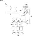
- Fig. 2 is an explanatory diagram illustrating a configuration of an optical system of the display device 10.
- the display device 10 mainly includes a light source 22, an optical member 23, and a light modulation element 24.
- the light source 22 is a light emitting diode (LED) mounted on a substrate.
- the light source 22 includes a red light source 22a configured to emit a red light beam R, a green light source 22b configured to emit a green light beam G, and a blue light source 22c configured to emit a blue light beam B.
- a red light source 22a configured to emit a red light beam R
- a green light source 22b configured to emit a green light beam G
- a blue light source 22c configured to emit a blue light beam B.
- the red light source 22a, the green light source 22b, and the blue light source 22c are simply referred to as the light source 22.
- the optical member 23 includes a mirror 41, dichroic mirrors 42 and 43, a reflection mirror 44, a convex lens 45, a prism 46, and a light projection lens 47.
- the red light beam R emitted from the red light source 22a is reflected by the mirror 41 and passes through the dichroic mirrors 42 and 43.
- the green light beam G emitted from the green light source 22b is reflected by the dichroic mirror 42 and passes through the dichroic mirror 43.
- the blue light beam B emitted from the blue light source 22c is reflected by the dichroic mirror 43.
- the light beams R, G, and B are reflected by the reflection mirror 44, distributed by the convex lens 45, and transmitted through the prism 46.
- the transmitted light beams R, G, and B are converted into the display light L by the light modulation element 24.
- the display light L is reflected by the prism 46, transmitted through the light projection lens 47, and projected (emitted).
- the light modulation element 24 is a reflective display element such as a Digital Mirror Device (DMD) or a Liquid Crystal On Silicon (LCOS).
- the light modulation element 24 is connected to a control substrate (not illustrated) and is controlled by the control substrate.
- Fig. 3 is an exploded perspective view of the screen unit 15.
- Fig. 4(A) is a perspective view of the screen unit 15
- Fig. 4(B) illustrates the screen unit 15 viewed from a side of accommodation openings 106 and 107 of a main holder 100
- Fig. 4(C) is a cross-sectional view taken along a line C-C in Fig. 4(B) .
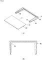
- Fig. 5(A) is a front view illustrating an appearance of a screen 60
- Fig. 5(B) is a perspective view illustrating a screen holder 70.
- Fig. 6(A) is a perspective view illustrating an appearance of a hot mirror 80 and a hot mirror packing 90
- Fig. 6(B) is a cross-sectional view of the hot mirror packing 90.
- Fig. 7 is a perspective view illustrating a state where a field lens 50, the screen 60 and the screen holder 70 are assembled.
- Fig. 8(A) and Fig. 8(B) are explanatory diagrams for explaining a positional relationship of the field lens 50, the screen 60, and the hot mirror 80.
- Fig. 8(A) is an explanatory diagram illustrating a positional relationship of the field lens 50, the screen 60, and the hot mirror 80 with respect to the first concave mirror 16
- Fig. 8(B) is an explanatory diagram illustrating a positional relationship of the hot mirror 80 in a case where the first concave mirror 16 is replaced with a third plane mirror 160.
- the screen unit 15 includes the field lens 50, the screen 60, the screen holder 70, the hot mirror 80, the hot mirror packing 90, and the main holder 100.
- the field lens 50 adjusts a direction of the display light L. That is, the field lens 50 has a function of guiding the display light L to the screen 60 at a predetermined distribution angle.
- the field lens 50 includes screen positioning pins 51 and a main holder positioning pin 52.
- the screen positioning pins 51 position and fix with respect to the screen holder 70 and the screen 60.
- the screen positioning pins 51 include two screen positioning pins 51.
- the two screen positioning pins 51 are provided asymmetrically (on a diagonal line) so that the screen 60 and the screen holder 70 are not attached to the field lens 50 with a front surface 62 and a rear surface 61 of the screen 60 reversed. That is, one of the screen positioning pins 51 is provided at a center in a short direction, and the other of the screen positioning pins 51 is provided near an end part in the short direction.
- the main holder positioning pin 52 is provided on a side located on an inner side in an insertion direction if the main holder positioning pin 52 is accommodated in the main holder 100.
- the screen 60 receives the display light L emitted from the field lens 50 on the rear surface 61 and displays a display image on the front surface 62.
- the screen 60 is formed of, for example, a polycarbonate resin, has a thin plate shape, and is flexible.
- the screen 60 includes a microlens array surface 63 and positioning holes 65.
- the microlens array surface 63 is a surface on which a plurality of convex microlenses provided on a base 66 are arranged, and is provided on the side of the rear surface 61 of the screen 60.
- the positioning holes 65 are positioned and fixed if the screen positioning pins 51 of the field lens 50 penetrates through the positioning holes 65.
- the positioning holes 65 are provided at positions corresponding to the screen positioning pins 51 of the field lens 50.
- the screen holder 70 is formed of a thin metal plate, and holds the screen 60.
- the screen holder 70 includes a front-surface plate spring 71, a side-surface plate spring 72, a clip 73, and positioning holes 75.
- the front-surface plate spring 71 (front-surface buffer member) is provided to face the front surface 62 of the screen 60 to abut against the main holder 100 in a direction orthogonal to the surface of the screen 60.
- the front-surface plate spring 71 buffers vibration of the screen 60 in a vertical direction (substantially in the vertical direction in Fig. 1 ) resulting from vibration of the vehicle. That is, the front-surface plate spring 71 buffers a contact with the main holder 100 resulting from the vibration of the screen 60 in the vertical direction.
- the side-surface plate spring 72 (side-surface buffer member) is provided on a side surface 76 exposed from the main holder 100 (see Fig. 5(B) ).
- the side-surface plate spring 72 is provided to abut against another structure such as the case 18 in the HUD 1.
- the side-surface plate spring 72 buffers vibration of the screen 60 in a horizontal direction (substantially in a left-right direction in Fig. 1 and in a front-back direction of a paper face of Fig. 1 ) resulting from vibration of the vehicle.
- the clip 73 fixes the screen 60.
- the clip 73 includes four clips 73 sandwiching and fixing the screen 60 in the vicinity of the four corners of the screen 60.
- the positioning holes 75 are positioned and fixed when the screen positioning pins 51 of the field lens 50 penetrates through the positioning holes 75.
- the positioning holes 75 are provided at positions corresponding to the screen positioning pins 51.
- the hot mirror 80 transmits the display image displayed on the screen 60 and reflects (and absorbs) infrared light.
- the hot mirror 80 includes one chamfered hot mirror-side corner part 81. If being held by the hot mirror packing 90, the hot mirror-side corner part 81 is located on the inner side in the insertion direction.
- the hot mirror packing 90 holds the hot mirror 80.
- the hot mirror packing 90 is a black member made of ethylene propylene diene rubber (EPDM), for example. Further, as illustrated in Fig. 6(A) and Fig. 6(B) , the hot mirror packing 90 is a U-shaped frame member including an insertion opening 91 on one side for inserting the hot mirror 80.
- the hot mirror packing 90 includes a slit 92 and a convex-shaped part 93.
- the slit 92 is provided on an inner peripheral side of the hot mirror packing 90, and the hot mirror 80 is inserted into and held by the slit 92. As illustrated in a region A of Fig. 6(A) and in Fig. 6(B) , the slit 92 includes, at a position corresponding to the hot mirror-side corner part 81, a packing-side corner part 95 chamfered to fit with the hot mirror-side corner part 81.
- the convex-shaped part 93 is provided on a side surface 96 of the hot mirror packing 90 exposed from the main holder 100.
- the convex-shaped part 93 is provided to abut against another structure such as the case 18 in the HUD 1, similarly to the side-surface plate spring 72 of the screen holder 70.
- the convex-shaped part 93 buffers vibration of the hot mirror 80 in the horizontal direction resulting from vibration of the vehicle.
- the thickness of the hot mirror packing 90 differs in the insertion direction.
- the thickness of the hot mirror packing 90, the inclination of the slit 92, and the accommodation angle of a hot mirror accommodation part 103 of the main holder 100 described later are suitably set, so that the surface of the hot mirror 80 inclined at a predetermined angle with respect to the surface of the screen 60 can be held.
- the main holder 100 is a metal housing made of, for example, a magnesium alloy and accommodates the field lens 50, the screen 60 held by the screen holder 70, and the hot mirror 80 held by the hot mirror packing 90.
- the main holder 100 includes a lens accommodation part 101, the hot mirror accommodation part 103, and a shielding wall 105.
- the lens accommodation part 101 accommodates the field lens 50 fixed to the screen holder 70 and the screen 60 from the accommodation opening 106.
- the lens accommodation part 101 includes a positioning hole 102 corresponding to the main holder positioning pin 52 of the field lens 50.
- the hot mirror accommodation part 103 accommodates the hot mirror 80 held by the hot mirror packing 90 from the accommodation opening 107.
- the shielding wall 105 shields the screen holder 70 so that the screen holder 70 accommodated in the lens accommodation part 101 is not visually recognized from the side of the hot mirror 80 or is not exposed to the side of the hot mirror 80. This prevents the metal screen holder 70 from being reflected by external light and prevents the display image from not being appropriately displayed.
- a first step the screen 60 is inserted into the clips 73 of the screen holder 70. At this time, the screen 60 is inserted into the clips 73 so that the positioning holes 65 of the screen 60 and the positioning holes 75 of the screen holder 70 align with each other.
- a second step as illustrated in Fig. 7 , the field lens 50 is attached to the screen 60 and the screen holder 70. At this time, the screen positioning pins 51 of the field lens 50 are attached to be reliably inserted into the positioning holes 65 and 75.
- the two sets of positioning holes 65 and 75 and screen positioning pins 51 are provided asymmetrically, and thus, it is possible to prevent the front surface 62 and the rear surface 61 of the screen 60 from being assembled improperly.
- the hot mirror 80 is inserted from the insertion opening 91 along the slit 92 into the hot mirror packing 90. At this time, the hot mirror 80 is inserted so that the chamfered hot mirror-side corner part 81 is on the inner side in the insertion direction and coincides with the position of the packing-side corner part 95. This prevents the front surface and the rear surface of the hot mirror 80 from being assembled improperly.
- the field lens 50 is accommodated in the lens accommodation part 101 of the main holder 100. At this time, as illustrated in Fig. 4(C) , the main holder positioning pin 52 of the field lens 50 is reliably inserted into the positioning hole 102 of the main holder 100. Thus, the field lens 50 and the screen 60 integrated with the field lens 50 are simultaneously positioned with respect to the main holder 100.
- the hot mirror 80 is accommodated in the hot mirror accommodation part 103 of the main holder 100. It is noted that the hot mirror 80 is inserted from the side of the insertion opening 91 of the hot mirror packing 90, into the accommodation opening 107.
- the screen unit 15 is assembled into the state illustrated in Fig. 4(A) to Fig. 4(C) through the above steps.
- the hot mirror 80 is arranged in a state in which the hot mirror 80 is inclined by the hot mirror packing 90 at an angle ⁇ with respect to an optical axis AX of the display light L passing through the field lens 50 and the screen 60 to face a lower-side end 16D of the first concave mirror 16. This prevents the display light L reflected on the back surface of the hot mirror 80 after passing through the screen 60 from moving again toward the first concave mirror 16, and thus, the display light L is unlikely to turn into stray light.
- the hot mirror 80 is inclined at an angle ⁇ with respect to the optical axis AX of the display light L passing through the field lens 50 and the screen 60 to face an upper-side end 160U of the third plane mirror 16.
- This provides the display light L reflected on the back surface of the hot mirror 80 after passing through the screen 60 from moving again toward the third plane mirror 160, and, and thus, the display light L is unlikely to turn into stray light. That is, it is preferable that an orientation in which the hot mirror 80 is inclined is reversed, depending on whether the concave mirror (the first concave mirror 16) or the plane mirror (the third plane mirror 160) is employed.
- the HUD 1 includes the screen unit 15 described above, and thus, the display image can be appropriately displayed. That is, the screen 60 is reliably held by the screen holder 70, and thus, it is possible to prevent an inappropriate image from being displayed to a viewer due to vibration or bending of the screen 60.
- the front-surface plate spring 71 and the side-surface plate spring 72 are provided to reduce vibration of the screen 60 resulting from vibration of the vehicle, and thus, a more appropriate image can be displayed.
- the screen holder 70 is provided, and thus, the screen 60 made of resin does not directly contact the main holder 100 made of metal. Therefore, it is possible to avoid a situation where parts of the screen 60 are chipped off due to friction with the main holder 100, the chipped-off powder adheres to the screen 60, and the display image is not appropriately displayed. That is, the screen holder 70 is made of metal, similarly to the main holder 100, and thus, the screen holder 70 does not experience chipping from friction.
- the screen 60 fixed to the screen holder 70 and the field lens 50 are assembled to form one member, and then attached to the main holder 100. Therefore, assembling errors can be reduced as compared with a case where the screen 60 and the field lens 50 are positioned separately in the main holder 100.
Landscapes
- Engineering & Computer Science (AREA)
- Physics & Mathematics (AREA)
- Mechanical Engineering (AREA)
- General Physics & Mathematics (AREA)
- Optics & Photonics (AREA)
- Chemical & Material Sciences (AREA)
- Combustion & Propulsion (AREA)
- Transportation (AREA)
- Instrument Panels (AREA)
Abstract
Description
- The present invention relates to a head-up display to be mounted on a vehicle or the like.
- A head-up display is mounted on a vehicle, and displays, via a transmission-reflection portion such as a windshield, a virtual image of various information such as information necessary for a driver during driving. Thus, the head-up display can display information (an image) superimposed on a scene in front of the vehicle. The driver can grasp necessary information without a large movement of his/her line of sight during driving.
- Display light for displaying an image is generated by a projection display device, for example. After a direction of the generated display light is adjusted by a field lens, the generated display light is displayed as an image on a screen (see, for example, Patent Document 1).
- Patent Document 1: Japanese Unexamined Patent Application Publication No.
2017-21302 - A head-up display is mounted on a vehicle, and thus, is used in a vibrating environment. Therefore, it is necessary to hold the screen and the field lens with as little vibration as possible to accurately display information as an image.
- The present invention has been made in view of these circumstances, and an object thereof is to provide a head-up display capable of reliably displaying a display image.
- To solve the problem described above, a head-up display according to the present invention includes: a display device configured to project display light; a field lens configured to adjust a direction of the display light; a thin-plate screen configured to receive the display light emitted from the field lens on a rear surface and display a display image on a front surface; a screen holder configured to hold the screen; and a main holder configured to accommodate the field lens and the screen held by the screen holder.
- In the head-up display according to the present invention, a display image can be reliably displayed.
-
-
Fig. 1 is an explanatory diagram illustrating an embodiment of a head-up display according to the present invention, and in particular, a configuration of an optical system. -
Fig. 2 is an explanatory diagram illustrating a configuration of an optical system of a display device. -
Fig. 3 is an exploded perspective view of a screen unit. -
Fig. 4(A) is a perspective view of the screen unit,Fig. 4(B) illustrates the screen unit viewed from a side of an accommodation opening of a main holder, andFig. 4(C) is a cross-sectional view taken along a line C-C inFig. 4(B) . -
Fig. 5(A) is a plan view illustrating an appearance of a screen, andFig. 5(B) is a perspective view illustrating a screen holder. -
Fig. 6(A) is a perspective view illustrating an appearance of a hot mirror and a hot mirror packing, andFig. 6(B) is a cross-sectional view of the hot mirror packing. -
Fig. 7 is a perspective view illustrating a state where a field lens, the screen and the screen holder are assembled. -
Fig. 8(A) and Fig. 8(B) are explanatory diagrams illustrating a positional relationship of the field lens, the screen, and the hot mirror. - An embodiment of a head-up display according to the present invention will be described with reference to the accompanying drawings. The head-up display according to the present invention is mounted on a vehicle such as an automobile. In the present embodiment, an example in which the head-up display according to the present invention is mounted on an automobile will be described.
-
Fig. 1 is an explanatory diagram illustrating an embodiment of the head-up display according to the present invention, and in particular, a configuration of an optical system. - A head-up display 1 (hereinafter, referred to as HUD 1) is arranged in an instrument panel of an automobile. The HUD 1 mainly includes a
projection display device 10, afirst plane mirror 13, asecond plane mirror 14, ascreen unit 15, a firstconcave mirror 16, a second concave mirror 17, and a case 18. The HUD 1 reflects display light L which represents a display image (image) and is generated by theprojection display device 10, on the first andsecond plane mirrors concave mirrors 16 and 17 and emits the display light L toward awindshield 2 of an automobile, which is an example of a transmission-reflection unit. The first and second plane mirrors 13 and 14 and the first and secondconcave mirrors 16 and 17 form a relay optical system. If placing aviewpoint 4 in aneye box 3 being an image visible region generated by the HUD 1, a viewer (mainly a driver) can visually recognize a virtual image V of the display image superimposed on the scene (real scene) in front of the vehicle. - The projection display device 10 (display device 10) generates and projects the display light L relating to the display image.
- The
first plane mirror 13 reflects the display light L generated and projected by thedisplay device 10. Thesecond plane mirror 14 further reflects the display light L reflected by thefirst plane mirror 13. - The
screen unit 15 receives the display light L reflected by thesecond plane mirror 14 and displays an image (real image). Details of thescreen unit 15 will be described later. The firstconcave mirror 16 has a curvature (reciprocal of the radius) that causes the display light L emitted from thescreen unit 15 to cross up and down (cross at a cross point C) before the display light L reaches the second concave mirror 17, and reflects the display light toward the second concave mirror 17. The second concave mirror 17 reflects the display light L reflected by the firstconcave mirror 16 toward thewindshield 2. - The case 18 houses the
display device 10, the first and second plane mirrors 13 and 14, thescreen unit 15, and the first and secondconcave mirrors 16 and 17. The case 18 has an opening 18a at a portion facing thewindshield 2. The opening 18a is covered by a lighttransmissive cover 19 being light transmissive. The display light L reflected by the second concave mirror 17 passes through the lighttransmissive cover 19 and is emitted from the HUD 1. -
Fig. 2 is an explanatory diagram illustrating a configuration of an optical system of thedisplay device 10. - The
display device 10 mainly includes alight source 22, anoptical member 23, and alight modulation element 24. - The
light source 22 is a light emitting diode (LED) mounted on a substrate. Thelight source 22 includes ared light source 22a configured to emit a red light beam R, agreen light source 22b configured to emit a green light beam G, and ablue light source 22c configured to emit a blue light beam B. Hereinafter, in a context in which thered light source 22a, thegreen light source 22b, and theblue light source 22c are not distinguished, they are simply referred to as thelight source 22. - The
optical member 23 includes amirror 41,dichroic mirrors reflection mirror 44, aconvex lens 45, aprism 46, and alight projection lens 47. - The red light beam R emitted from the
red light source 22a is reflected by themirror 41 and passes through thedichroic mirrors green light source 22b is reflected by thedichroic mirror 42 and passes through thedichroic mirror 43. The blue light beam B emitted from theblue light source 22c is reflected by thedichroic mirror 43. The light beams R, G, and B are reflected by thereflection mirror 44, distributed by theconvex lens 45, and transmitted through theprism 46. The transmitted light beams R, G, and B are converted into the display light L by thelight modulation element 24. The display light L is reflected by theprism 46, transmitted through thelight projection lens 47, and projected (emitted). - The
light modulation element 24 is a reflective display element such as a Digital Mirror Device (DMD) or a Liquid Crystal On Silicon (LCOS). Thelight modulation element 24 is connected to a control substrate (not illustrated) and is controlled by the control substrate. -
Fig. 3 is an exploded perspective view of thescreen unit 15. -
Fig. 4(A) is a perspective view of thescreen unit 15,Fig. 4(B) illustrates thescreen unit 15 viewed from a side ofaccommodation openings main holder 100, andFig. 4(C) is a cross-sectional view taken along a line C-C inFig. 4(B) . -
Fig. 5(A) is a front view illustrating an appearance of ascreen 60, andFig. 5(B) is a perspective view illustrating ascreen holder 70. -
Fig. 6(A) is a perspective view illustrating an appearance of ahot mirror 80 and ahot mirror packing 90, andFig. 6(B) is a cross-sectional view of thehot mirror packing 90. -
Fig. 7 is a perspective view illustrating a state where afield lens 50, thescreen 60 and thescreen holder 70 are assembled. -
Fig. 8(A) and Fig. 8(B) are explanatory diagrams for explaining a positional relationship of thefield lens 50, thescreen 60, and thehot mirror 80.Fig. 8(A) is an explanatory diagram illustrating a positional relationship of thefield lens 50, thescreen 60, and thehot mirror 80 with respect to the firstconcave mirror 16, andFig. 8(B) is an explanatory diagram illustrating a positional relationship of thehot mirror 80 in a case where the firstconcave mirror 16 is replaced with athird plane mirror 160. - The
screen unit 15 includes thefield lens 50, thescreen 60, thescreen holder 70, thehot mirror 80, the hot mirror packing 90, and themain holder 100. - The
field lens 50 adjusts a direction of the display light L. That is, thefield lens 50 has a function of guiding the display light L to thescreen 60 at a predetermined distribution angle. Thefield lens 50 includes screen positioning pins 51 and a mainholder positioning pin 52. - The screen positioning pins 51 (positioning members) position and fix with respect to the
screen holder 70 and thescreen 60. The screen positioning pins 51 include two screen positioning pins 51. The two screen positioning pins 51 are provided asymmetrically (on a diagonal line) so that thescreen 60 and thescreen holder 70 are not attached to thefield lens 50 with afront surface 62 and a rear surface 61 of thescreen 60 reversed. That is, one of the screen positioning pins 51 is provided at a center in a short direction, and the other of the screen positioning pins 51 is provided near an end part in the short direction. The mainholder positioning pin 52 is provided on a side located on an inner side in an insertion direction if the mainholder positioning pin 52 is accommodated in themain holder 100. - The
screen 60 receives the display light L emitted from thefield lens 50 on the rear surface 61 and displays a display image on thefront surface 62. Thescreen 60 is formed of, for example, a polycarbonate resin, has a thin plate shape, and is flexible. Thescreen 60 includes amicrolens array surface 63 and positioning holes 65. Themicrolens array surface 63 is a surface on which a plurality of convex microlenses provided on abase 66 are arranged, and is provided on the side of the rear surface 61 of thescreen 60. The positioning holes 65 are positioned and fixed if the screen positioning pins 51 of thefield lens 50 penetrates through the positioning holes 65. The positioning holes 65 are provided at positions corresponding to the screen positioning pins 51 of thefield lens 50. - The
screen holder 70 is formed of a thin metal plate, and holds thescreen 60. Thescreen holder 70 includes a front-surface plate spring 71, a side-surface plate spring 72, aclip 73, and positioning holes 75. - The front-surface plate spring 71 (front-surface buffer member) is provided to face the
front surface 62 of thescreen 60 to abut against themain holder 100 in a direction orthogonal to the surface of thescreen 60. The front-surface plate spring 71 buffers vibration of thescreen 60 in a vertical direction (substantially in the vertical direction inFig. 1 ) resulting from vibration of the vehicle. That is, the front-surface plate spring 71 buffers a contact with themain holder 100 resulting from the vibration of thescreen 60 in the vertical direction. - The side-surface plate spring 72 (side-surface buffer member) is provided on a
side surface 76 exposed from the main holder 100 (seeFig. 5(B) ). The side-surface plate spring 72 is provided to abut against another structure such as the case 18 in the HUD 1. The side-surface plate spring 72 buffers vibration of thescreen 60 in a horizontal direction (substantially in a left-right direction inFig. 1 and in a front-back direction of a paper face ofFig. 1 ) resulting from vibration of the vehicle. - The
clip 73 fixes thescreen 60. Theclip 73 includes fourclips 73 sandwiching and fixing thescreen 60 in the vicinity of the four corners of thescreen 60. - The positioning holes 75 are positioned and fixed when the screen positioning pins 51 of the
field lens 50 penetrates through the positioning holes 75. The positioning holes 75 are provided at positions corresponding to the screen positioning pins 51. - The
hot mirror 80 transmits the display image displayed on thescreen 60 and reflects (and absorbs) infrared light. Thehot mirror 80 includes one chamfered hot mirror-side corner part 81. If being held by the hot mirror packing 90, the hot mirror-side corner part 81 is located on the inner side in the insertion direction. - The hot mirror packing 90 holds the
hot mirror 80. The hot mirror packing 90 is a black member made of ethylene propylene diene rubber (EPDM), for example. Further, as illustrated inFig. 6(A) and Fig. 6(B) , the hot mirror packing 90 is a U-shaped frame member including aninsertion opening 91 on one side for inserting thehot mirror 80. The hot mirror packing 90 includes aslit 92 and a convex-shapedpart 93. - The
slit 92 is provided on an inner peripheral side of the hot mirror packing 90, and thehot mirror 80 is inserted into and held by theslit 92. As illustrated in a region A ofFig. 6(A) and inFig. 6(B) , theslit 92 includes, at a position corresponding to the hot mirror-side corner part 81, a packing-side corner part 95 chamfered to fit with the hot mirror-side corner part 81. - The convex-shaped
part 93 is provided on aside surface 96 of the hot mirror packing 90 exposed from themain holder 100. The convex-shapedpart 93 is provided to abut against another structure such as the case 18 in the HUD 1, similarly to the side-surface plate spring 72 of thescreen holder 70. The convex-shapedpart 93 buffers vibration of thehot mirror 80 in the horizontal direction resulting from vibration of the vehicle. - As illustrated in
Fig. 6(A) , the thickness of the hot mirror packing 90 differs in the insertion direction. The thickness of the hot mirror packing 90, the inclination of theslit 92, and the accommodation angle of a hotmirror accommodation part 103 of themain holder 100 described later are suitably set, so that the surface of thehot mirror 80 inclined at a predetermined angle with respect to the surface of thescreen 60 can be held. - The
main holder 100 is a metal housing made of, for example, a magnesium alloy and accommodates thefield lens 50, thescreen 60 held by thescreen holder 70, and thehot mirror 80 held by the hot mirror packing 90. Themain holder 100 includes alens accommodation part 101, the hotmirror accommodation part 103, and ashielding wall 105. - The
lens accommodation part 101 accommodates thefield lens 50 fixed to thescreen holder 70 and thescreen 60 from theaccommodation opening 106. Thelens accommodation part 101 includes apositioning hole 102 corresponding to the mainholder positioning pin 52 of thefield lens 50. The hotmirror accommodation part 103 accommodates thehot mirror 80 held by the hot mirror packing 90 from theaccommodation opening 107. The shieldingwall 105 shields thescreen holder 70 so that thescreen holder 70 accommodated in thelens accommodation part 101 is not visually recognized from the side of thehot mirror 80 or is not exposed to the side of thehot mirror 80. This prevents themetal screen holder 70 from being reflected by external light and prevents the display image from not being appropriately displayed. - Next, a procedure for assembling the
screen unit 15 will be described. - In a first step, the
screen 60 is inserted into theclips 73 of thescreen holder 70. At this time, thescreen 60 is inserted into theclips 73 so that the positioning holes 65 of thescreen 60 and the positioning holes 75 of thescreen holder 70 align with each other. In a second step, as illustrated inFig. 7 , thefield lens 50 is attached to thescreen 60 and thescreen holder 70. At this time, the screen positioning pins 51 of thefield lens 50 are attached to be reliably inserted into the positioning holes 65 and 75. The two sets of positioning holes 65 and 75 and screen positioning pins 51 are provided asymmetrically, and thus, it is possible to prevent thefront surface 62 and the rear surface 61 of thescreen 60 from being assembled improperly. - In a third step, as illustrated in
Fig. 6(A) , thehot mirror 80 is inserted from theinsertion opening 91 along theslit 92 into the hot mirror packing 90. At this time, thehot mirror 80 is inserted so that the chamfered hot mirror-side corner part 81 is on the inner side in the insertion direction and coincides with the position of the packing-side corner part 95. This prevents the front surface and the rear surface of thehot mirror 80 from being assembled improperly. In a fourth step, thefield lens 50 is accommodated in thelens accommodation part 101 of themain holder 100. At this time, as illustrated inFig. 4(C) , the mainholder positioning pin 52 of thefield lens 50 is reliably inserted into thepositioning hole 102 of themain holder 100. Thus, thefield lens 50 and thescreen 60 integrated with thefield lens 50 are simultaneously positioned with respect to themain holder 100. - In a fifth step, the
hot mirror 80 is accommodated in the hotmirror accommodation part 103 of themain holder 100. It is noted that thehot mirror 80 is inserted from the side of theinsertion opening 91 of the hot mirror packing 90, into theaccommodation opening 107. - The
screen unit 15 is assembled into the state illustrated inFig. 4(A) to Fig. 4(C) through the above steps. - Description proceeds referring to
Fig. 8(A) and Fig. 8(B) . As illustrated inFig. 8(A) , thehot mirror 80 is arranged in a state in which thehot mirror 80 is inclined by the hot mirror packing 90 at an angle θ with respect to an optical axis AX of the display light L passing through thefield lens 50 and thescreen 60 to face a lower-side end 16D of the firstconcave mirror 16. This prevents the display light L reflected on the back surface of thehot mirror 80 after passing through thescreen 60 from moving again toward the firstconcave mirror 16, and thus, the display light L is unlikely to turn into stray light. - Further, as illustrated in
Fig. 8(B) , if the firstconcave mirror 16 is replaced by thethird plane mirror 160, it is preferable that thehot mirror 80 is inclined at an angle θ with respect to the optical axis AX of the display light L passing through thefield lens 50 and thescreen 60 to face an upper-side end 160U of thethird plane mirror 16. This provides the display light L reflected on the back surface of thehot mirror 80 after passing through thescreen 60 from moving again toward thethird plane mirror 160, and, and thus, the display light L is unlikely to turn into stray light. That is, it is preferable that an orientation in which thehot mirror 80 is inclined is reversed, depending on whether the concave mirror (the first concave mirror 16) or the plane mirror (the third plane mirror 160) is employed. - The HUD 1 according to the present embodiment includes the
screen unit 15 described above, and thus, the display image can be appropriately displayed. That is, thescreen 60 is reliably held by thescreen holder 70, and thus, it is possible to prevent an inappropriate image from being displayed to a viewer due to vibration or bending of thescreen 60. In particular, the front-surface plate spring 71 and the side-surface plate spring 72 are provided to reduce vibration of thescreen 60 resulting from vibration of the vehicle, and thus, a more appropriate image can be displayed. - Further, the
screen holder 70 is provided, and thus, thescreen 60 made of resin does not directly contact themain holder 100 made of metal. Therefore, it is possible to avoid a situation where parts of thescreen 60 are chipped off due to friction with themain holder 100, the chipped-off powder adheres to thescreen 60, and the display image is not appropriately displayed. That is, thescreen holder 70 is made of metal, similarly to themain holder 100, and thus, thescreen holder 70 does not experience chipping from friction. - Further, the
screen 60 fixed to thescreen holder 70 and thefield lens 50 are assembled to form one member, and then attached to themain holder 100. Therefore, assembling errors can be reduced as compared with a case where thescreen 60 and thefield lens 50 are positioned separately in themain holder 100. - Although some embodiments of the present invention have been described, these embodiments are presented by way of example and are not intended to limit the scope of the invention. These novel embodiments can be implemented in various other forms, and various omissions, replacements, and changes can be made without departing from the scope of the invention. These embodiments and modifications thereof are included in the scope and gist of the invention, and are included in the invention described in the claims and the equivalents thereof.
-
- 1
- Head-up display (HUD)
- 2
- Windshield
- 3
- Eye box
- 4
- Viewpoint
- 10
- Projection display device (display device)
- 13
- First plane mirror
- 14
- Second plane mirror
- 15
- Screen unit
- 16
- First concave mirror
- 17
- Second concave mirror
- 18
- Case
- 18a
- Opening
- 19
- Light transmissive cover
- 22
- Light source
- 22a
- Red light source
- 22b
- Green light source
- 22c
- Blue light source
- 23
- Optical member
- 24
- Light modulation element
- 41
- Mirror
- 42, 43
- Dichroic mirror
- 44
- Reflection mirror
- 45
- Convex lens
- 46
- Prism
- 47
- Light projection lens
- 50
- Field lens
- 51
- Screen positioning pin
- 52
- Main holder positioning pin
- 60
- Screen
- 61
- Rear surface
- 62
- Front surface
- 63
- Microlens array surface
- 65, 75, 102
- Positioning hole
- 66
- Base
- 70
- Screen holder
- 71
- Front-surface plate spring
- 72
- Side-surface plate spring
- 73
- Clip
- 76, 96
- Side surface
- 80
- Hot mirror
- 81
- Hot mirror-side corner part
- 90
- Hot mirror packing
- 91
- Insertion opening
- 92
- Slit
- 93
- convex-shaped part
- 95
- Packing-side corner part
- 100
- Main holder
- 101
- Lens accommodation part
- 103
- Hot mirror accommodation part
- 105
- Shielding wall
- 106, 107
- Accommodation opening
Claims (5)
- A head-up display comprising:a display device configured to project display light;a field lens configured to adjust a direction of the display light;a thin-plate screen configured to receive the display light emitted from the field lens on a rear surface and display a display image on a front surface;a screen holder configured to hold the screen; anda main holder configured to accommodate the field lens and the screen held by the screen holder.
- The head-up display according to claim 1, wherein the screen holder includes a front-surface buffer member abutting against the main holder on a side of the front surface of the screen in a direction orthogonal to a surface of the screen, the front-surface buffer member being configured to buffer vibration of the screen with respect to the main holder.
- The head-up display according to claim 1 or 2, wherein the screen holder includes a side surface exposed from the main holder, and a side-surface buffer member provided on the side surface, the side-surface buffer member being configured to buffer vibration of the screen.
- The head-up display according to any one of claims 1 to 3, wherein the screen holder includes a plurality of clips configured to fix the screen.
- The head-up display according to any one of claims 1 to 4, wherein the field lens includes a positioning member configured to position and fix the screen holder and the screen held by the screen holder, and
the main holder includes a lens accommodation unit configured to accommodate the field lens fixed to the screen holder and the screen.
Applications Claiming Priority (2)
| Application Number | Priority Date | Filing Date | Title |
|---|---|---|---|
| JP2017230843 | 2017-11-30 | ||
| PCT/JP2018/043318 WO2019107294A1 (en) | 2017-11-30 | 2018-11-26 | Head-up display |
Publications (2)
| Publication Number | Publication Date |
|---|---|
| EP3719560A1 true EP3719560A1 (en) | 2020-10-07 |
| EP3719560A4 EP3719560A4 (en) | 2021-08-04 |
Family
ID=66665131
Family Applications (1)
| Application Number | Title | Priority Date | Filing Date |
|---|---|---|---|
| EP18882977.4A Withdrawn EP3719560A4 (en) | 2017-11-30 | 2018-11-26 | HEAD-UP DISPLAY UNIT |
Country Status (5)
| Country | Link |
|---|---|
| US (1) | US11485229B2 (en) |
| EP (1) | EP3719560A4 (en) |
| JP (1) | JP7188396B2 (en) |
| CN (1) | CN111386488A (en) |
| WO (1) | WO2019107294A1 (en) |
Families Citing this family (4)
| Publication number | Priority date | Publication date | Assignee | Title |
|---|---|---|---|---|
| KR102883927B1 (en) * | 2019-12-20 | 2025-11-07 | 현대모비스 주식회사 | Head-up display apparatus for vehicle having improved combining structure |
| JP7476758B2 (en) * | 2020-10-26 | 2024-05-01 | 日本精機株式会社 | Head-up display device |
| JP7436414B2 (en) * | 2021-03-26 | 2024-02-21 | トヨタ自動車株式会社 | vehicle structure |
| US11562653B1 (en) | 2021-11-17 | 2023-01-24 | Beta Air, Llc | Systems and methods for in-flight re-routing of an electric aircraft |
Family Cites Families (17)
| Publication number | Priority date | Publication date | Assignee | Title |
|---|---|---|---|---|
| TW200734680A (en) | 2005-10-26 | 2007-09-16 | Nippon Sheet Glass Co Ltd | Vehicle-mounted stereoimage display unit |
| JP2009109798A (en) * | 2007-10-31 | 2009-05-21 | Nippon Seiki Co Ltd | Headup display device |
| JP5674032B2 (en) * | 2011-03-25 | 2015-02-18 | 日本精機株式会社 | Head-up display device |
| EP2876483B1 (en) * | 2012-07-20 | 2017-10-18 | JVC KENWOOD Corporation | Image display apparatus |
| JP5910386B2 (en) * | 2012-07-20 | 2016-04-27 | 株式会社Jvcケンウッド | Image display device |
| JP6044838B2 (en) * | 2013-04-04 | 2016-12-14 | 日本精機株式会社 | Head-up display device |
| JP6503717B2 (en) * | 2014-12-09 | 2019-04-24 | 日本精機株式会社 | Head-up display device |
| JP2016159779A (en) * | 2015-03-02 | 2016-09-05 | シャープ株式会社 | Image display device |
| JP2017021302A (en) | 2015-07-15 | 2017-01-26 | 日本精機株式会社 | Head-up display |
| JP6597022B2 (en) | 2015-07-28 | 2019-10-30 | 日本精機株式会社 | Head-up display device |
| JP6455724B2 (en) * | 2015-08-25 | 2019-01-23 | パナソニックIpマネジメント株式会社 | Image display device |
| US9835859B2 (en) * | 2015-08-25 | 2017-12-05 | Panasonic Intellectual Property Management Co., Ltd. | Image display device |
| JP6254988B2 (en) * | 2015-10-21 | 2017-12-27 | 矢崎総業株式会社 | Head-up display device |
| JP6696174B2 (en) * | 2015-12-25 | 2020-05-20 | 日本精機株式会社 | Display device |
| US10031336B2 (en) | 2016-01-26 | 2018-07-24 | Panasonic Intellectual Property Management Co., Ltd. | Image display device |
| JP6675114B2 (en) * | 2016-01-26 | 2020-04-01 | パナソニックIpマネジメント株式会社 | Image display device |
| JP6801206B2 (en) * | 2016-03-22 | 2020-12-16 | 日本精機株式会社 | Display device |
-
2018
- 2018-11-26 JP JP2019557208A patent/JP7188396B2/en active Active
- 2018-11-26 EP EP18882977.4A patent/EP3719560A4/en not_active Withdrawn
- 2018-11-26 CN CN201880076354.0A patent/CN111386488A/en active Pending
- 2018-11-26 WO PCT/JP2018/043318 patent/WO2019107294A1/en not_active Ceased
- 2018-11-26 US US16/761,654 patent/US11485229B2/en active Active
Also Published As
| Publication number | Publication date |
|---|---|
| WO2019107294A1 (en) | 2019-06-06 |
| EP3719560A4 (en) | 2021-08-04 |
| JP7188396B2 (en) | 2022-12-13 |
| CN111386488A (en) | 2020-07-07 |
| US11485229B2 (en) | 2022-11-01 |
| US20210162864A1 (en) | 2021-06-03 |
| JPWO2019107294A1 (en) | 2020-12-24 |
Similar Documents
| Publication | Publication Date | Title |
|---|---|---|
| EP3185061B1 (en) | Projection device and head-up display device | |
| EP3447561B1 (en) | Head-up display device | |
| US11485229B2 (en) | Head-up display | |
| US6752500B1 (en) | Rear surface projection type display device | |
| JP6848219B2 (en) | Image display device | |
| EP3415973B1 (en) | Display device and head-up display | |
| EP3064985B1 (en) | Temperature control device, image display apparatus and vehicle | |
| CN217561836U (en) | head-up display | |
| EP3415974A1 (en) | Display device and head-up display | |
| EP3677947A1 (en) | Headup display device | |
| JP3702890B2 (en) | Optical assembly and projector | |
| JP6984359B2 (en) | Head-up display | |
| CN219496811U (en) | Display device | |
| JP6296862B2 (en) | Image display device | |
| JP2018180253A (en) | Vehicle display device | |
| JP2012189761A (en) | Projector and image display system | |
| JP6969424B2 (en) | Plane mirror unit | |
| JP2017142284A (en) | Display device and head-up display | |
| JP2018530771A (en) | Compact head-up display | |
| CN101160548A (en) | image display device | |
| CN215910732U (en) | Head-up display device | |
| JP6391269B2 (en) | Image display device | |
| JP2013235155A (en) | Projector | |
| US20110216422A1 (en) | Image Display Device | |
| US20250199391A1 (en) | Image projection device |
Legal Events
| Date | Code | Title | Description |
|---|---|---|---|
| STAA | Information on the status of an ep patent application or granted ep patent |
Free format text: STATUS: THE INTERNATIONAL PUBLICATION HAS BEEN MADE |
|
| PUAI | Public reference made under article 153(3) epc to a published international application that has entered the european phase |
Free format text: ORIGINAL CODE: 0009012 |
|
| STAA | Information on the status of an ep patent application or granted ep patent |
Free format text: STATUS: REQUEST FOR EXAMINATION WAS MADE |
|
| 17P | Request for examination filed |
Effective date: 20200428 |
|
| AK | Designated contracting states |
Kind code of ref document: A1 Designated state(s): AL AT BE BG CH CY CZ DE DK EE ES FI FR GB GR HR HU IE IS IT LI LT LU LV MC MK MT NL NO PL PT RO RS SE SI SK SM TR |
|
| AX | Request for extension of the european patent |
Extension state: BA ME |
|
| DAV | Request for validation of the european patent (deleted) | ||
| DAX | Request for extension of the european patent (deleted) | ||
| A4 | Supplementary search report drawn up and despatched |
Effective date: 20210706 |
|
| RIC1 | Information provided on ipc code assigned before grant |
Ipc: G02B 27/01 20060101AFI20210630BHEP Ipc: B60K 35/00 20060101ALI20210630BHEP Ipc: B60R 11/02 20060101ALI20210630BHEP |
|
| STAA | Information on the status of an ep patent application or granted ep patent |
Free format text: STATUS: THE APPLICATION IS DEEMED TO BE WITHDRAWN |
|
| 18D | Application deemed to be withdrawn |
Effective date: 20220203 |