EP3719540A1 - Multi-line laser radar - Google Patents
Multi-line laser radar Download PDFInfo
- Publication number
- EP3719540A1 EP3719540A1 EP18895823.5A EP18895823A EP3719540A1 EP 3719540 A1 EP3719540 A1 EP 3719540A1 EP 18895823 A EP18895823 A EP 18895823A EP 3719540 A1 EP3719540 A1 EP 3719540A1
- Authority
- EP
- European Patent Office
- Prior art keywords
- laser
- radar
- line
- laser beam
- laser beams
- Prior art date
- Legal status (The legal status is an assumption and is not a legal conclusion. Google has not performed a legal analysis and makes no representation as to the accuracy of the status listed.)
- Granted
Links
Images



Classifications
-
- G—PHYSICS
- G01—MEASURING; TESTING
- G01S—RADIO DIRECTION-FINDING; RADIO NAVIGATION; DETERMINING DISTANCE OR VELOCITY BY USE OF RADIO WAVES; LOCATING OR PRESENCE-DETECTING BY USE OF THE REFLECTION OR RERADIATION OF RADIO WAVES; ANALOGOUS ARRANGEMENTS USING OTHER WAVES
- G01S7/00—Details of systems according to groups G01S13/00, G01S15/00, G01S17/00
- G01S7/48—Details of systems according to groups G01S13/00, G01S15/00, G01S17/00 of systems according to group G01S17/00
- G01S7/481—Constructional features, e.g. arrangements of optical elements
- G01S7/4814—Constructional features, e.g. arrangements of optical elements of transmitters alone
- G01S7/4815—Constructional features, e.g. arrangements of optical elements of transmitters alone using multiple transmitters
-
- G—PHYSICS
- G01—MEASURING; TESTING
- G01S—RADIO DIRECTION-FINDING; RADIO NAVIGATION; DETERMINING DISTANCE OR VELOCITY BY USE OF RADIO WAVES; LOCATING OR PRESENCE-DETECTING BY USE OF THE REFLECTION OR RERADIATION OF RADIO WAVES; ANALOGOUS ARRANGEMENTS USING OTHER WAVES
- G01S17/00—Systems using the reflection or reradiation of electromagnetic waves other than radio waves, e.g. lidar systems
- G01S17/02—Systems using the reflection of electromagnetic waves other than radio waves
- G01S17/06—Systems determining position data of a target
- G01S17/42—Simultaneous measurement of distance and other co-ordinates
-
- G—PHYSICS
- G01—MEASURING; TESTING
- G01S—RADIO DIRECTION-FINDING; RADIO NAVIGATION; DETERMINING DISTANCE OR VELOCITY BY USE OF RADIO WAVES; LOCATING OR PRESENCE-DETECTING BY USE OF THE REFLECTION OR RERADIATION OF RADIO WAVES; ANALOGOUS ARRANGEMENTS USING OTHER WAVES
- G01S17/00—Systems using the reflection or reradiation of electromagnetic waves other than radio waves, e.g. lidar systems
- G01S17/88—Lidar systems specially adapted for specific applications
- G01S17/93—Lidar systems specially adapted for specific applications for anti-collision purposes
- G01S17/931—Lidar systems specially adapted for specific applications for anti-collision purposes of land vehicles
-
- G—PHYSICS
- G01—MEASURING; TESTING
- G01S—RADIO DIRECTION-FINDING; RADIO NAVIGATION; DETERMINING DISTANCE OR VELOCITY BY USE OF RADIO WAVES; LOCATING OR PRESENCE-DETECTING BY USE OF THE REFLECTION OR RERADIATION OF RADIO WAVES; ANALOGOUS ARRANGEMENTS USING OTHER WAVES
- G01S7/00—Details of systems according to groups G01S13/00, G01S15/00, G01S17/00
- G01S7/48—Details of systems according to groups G01S13/00, G01S15/00, G01S17/00 of systems according to group G01S17/00
- G01S7/481—Constructional features, e.g. arrangements of optical elements
- G01S7/4817—Constructional features, e.g. arrangements of optical elements relating to scanning
-
- G—PHYSICS
- G01—MEASURING; TESTING
- G01S—RADIO DIRECTION-FINDING; RADIO NAVIGATION; DETERMINING DISTANCE OR VELOCITY BY USE OF RADIO WAVES; LOCATING OR PRESENCE-DETECTING BY USE OF THE REFLECTION OR RERADIATION OF RADIO WAVES; ANALOGOUS ARRANGEMENTS USING OTHER WAVES
- G01S7/00—Details of systems according to groups G01S13/00, G01S15/00, G01S17/00
- G01S7/48—Details of systems according to groups G01S13/00, G01S15/00, G01S17/00 of systems according to group G01S17/00
- G01S7/481—Constructional features, e.g. arrangements of optical elements
- G01S7/4818—Constructional features, e.g. arrangements of optical elements using optical fibres
-
- G—PHYSICS
- G02—OPTICS
- G02B—OPTICAL ELEMENTS, SYSTEMS OR APPARATUS
- G02B26/00—Optical devices or arrangements for the control of light using movable or deformable optical elements
- G02B26/08—Optical devices or arrangements for the control of light using movable or deformable optical elements for controlling the direction of light
- G02B26/10—Scanning systems
- G02B26/105—Scanning systems with one or more pivoting mirrors or galvano-mirrors
-
- G—PHYSICS
- G02—OPTICS
- G02B—OPTICAL ELEMENTS, SYSTEMS OR APPARATUS
- G02B26/00—Optical devices or arrangements for the control of light using movable or deformable optical elements
- G02B26/08—Optical devices or arrangements for the control of light using movable or deformable optical elements for controlling the direction of light
- G02B26/10—Scanning systems
- G02B26/12—Scanning systems using multifaceted mirrors
- G02B26/123—Multibeam scanners, e.g. using multiple light sources or beam splitters
Definitions
- Embodiments of this application relate to the field of laser detection technologies, and in particular, to a multi-line laser radar.
- a laser radar is a radar system that detecting characteristics such as a location and a speed of a target by emitting a laser beam.
- the laser radar may be classified into a panoramic laser radar and a forward-looking laser radar based on a detection range.
- a detection range of the panoramic laser radar is 360 degrees, and a detection range of the forward-looking laser radar is 90 degrees to 110 degrees straight ahead. Redundant information in information detected by the forward-looking laser radar is less than that of the panoramic laser radar, and therefore the forward-looking laser radar is more in line with a development trend of the intelligent transportation field.
- FIG. 1 is a schematic structural diagram of a four-line laser radar.
- the four-line laser radar includes two lasers, one four-channel detector array, and one scanning rotating mirror, where the two lasers include a first laser 111 and a second laser 112, the four-channel detector array includes a first detector 121, a second detector 122, a third detector 123, and a fourth detector 124, and the scanning rotating mirror is a double-sided parallel prism 13.
- the first laser 111 and the second laser 112 are arranged in parallel in a vertical direction, and are configured to emit the laser beam.
- the double-sided parallel prism 13 is configured to reflect the laser beam emitted by the first laser 111 and the second laser 112.
- the first detector 121 and the second detector 122 are configured to receive echo signals of the laser beam emitted by the first laser 111, and the third detector 123 and the fourth detector 124 are configured to receive echo signals of the laser beam emitted by the second laser 112, so as to implement four-line scanning.
- the detectors need to work under a high frequency and a high voltage. Limited by a volume of the laser radar, a distance between the detectors is limited, so that a signal crosstalk between the detectors is relatively serious, thereby causing unstable working performance of the laser radar.
- Embodiments of this application provide a multi-line laser radar, so as to resolve a problem of unstable working performance of a multi-line laser radar provided by a related technology.
- an embodiment of this application provides a multi-line laser radar, where the multi-line laser radar includes a first radar component.
- the first radar component includes n lasers, an optical collimating unit, a scanning rotating mirror, and a detector, where n is an integer greater than 1.
- Each laser of the n lasers is configured to emit one laser beam to the optical collimating unit.
- the optical collimating unit is configured to collimate n laser beams, and the collimated n laser beams are incident on a target reflector of the scanning rotating mirror, where the scanning rotating mirror includes a rotation axis and m reflectors rotating around the rotation axis, a rotation plane of the rotation axis is perpendicular to an arrangement direction of the collimated n laser beams, the target reflector is a reflector that is in the m reflectors and that is currently rotated to a position opposite to an emergent direction of the collimated n laser beams, and m is an integer greater than 1.
- the target reflector is configured to reflect the received collimated n laser beams, where the reflected n laser beams are incident on a detection area of the first radar component, and at least two reflectors existing in the m reflectors have different reflection angles for a same laser beam.
- the detector is configured to receive echo signals of the reflected n laser beams in the detection area.
- the multi-line laser radar includes the first radar component that uses a "multiple transmit and single receive" structure, where only one detector is disposed in the first radar component, and a quantity of detectors is reduced as much as possible on a premise of implementing multi-line scanning, so as to reduce a signal crosstalk between detectors. Therefore, working performance of the multi-line laser radar can be improved, and hardware costs required for the multi-line laser radar can be reduced.
- the scanning rotating mirror includes the at least two reflectors that have different reflection angles for a same laser beam. Therefore, one laser can implement at least two-line scanning, and the quantity of scanning lines of the multi-line laser radar can be increased without increasing a quantity of lasers.
- all the reflectors have different reflection angles for a same laser beam. Therefore, one laser can implement m-line scanning, and a quantity of scanning lines of the multi-line laser radar can be increased without increasing a quantity of lasers.
- included angles between normal lines of planes on which the reflectors are located and the straight line on which the rotation axis is located are in arithmetic progression, and included angles between laser beams subsequently reflected by the scanning rotating mirror are also in arithmetic progression.
- the laser beams are arranged more evenly.
- the first radar component further includes: n optical fibers.
- the n lasers are in a one-to-one correspondence with the n optical fibers.
- the optical fiber is configured to export the laser beam emitted by the laser to the optical collimating unit.
- the laser beam is exported to the optical collimating unit by using the optical fiber, and the optical fibers are densely arranged to implement dense arrangement of laser beams.
- using the optical fiber to export the laser beam to the optical collimating unit can make a layout of components in the multi-line laser radar more flexible and convenient, so as to help improve positioning precision between an optical source and the optical collimating unit, and further effectively shape an irregular laser beam emitted by the laser into a flat top laser beam with a circular profile.
- the flat top laser beam with the circular profile has more uniform and centralized energy distribution, so as to help improve a detection distance of the multi-line laser radar.
- a light outlet point of the optical fiber is located on a focal plane of the optical collimating unit.
- the light outlet point of the optical fiber is disposed on the focal plane of the optical collimation, so as to help better obtain a collimated beam.
- the fiber core spacing between two adjacent optical fibers is set, so that an included angle formed when the laser beams are emitted through the optical collimating unit is relatively small, the detector can completely receive echo signals of the laser beams, and this help improve accuracy of target detection.
- the receiving field of view of the detector is set properly, so that the detector can receive the echo signal of the laser beam at a maximum degree, and further improve accuracy of target detection.
- all the lasers work in a time-division mode.
- all the lasers work in a time-division mode, so that a case in which the detector falsely considers an echo signal of a laser beam as an echo signal of another laser beam can be avoided, so as to avoid signal misjudgment.
- an arrangement direction of the collimated n laser beams is a vertical direction.
- the arrangement direction of the laser beams is set to the vertical direction, so that the multi-line laser radar can detect an obstacle in front, and can be applied to the intelligent transportation field.
- a multi-line laser radar includes a first radar component that uses a "multiple transmit and single receive" structure, where only one detector is disposed in the first radar component, and a quantity of detectors is reduced as much as possible on a premise of implementing multi-line scanning, so as to reduce a signal crosstalk between detectors. Therefore, working performance of the multi-line laser radar can be improved, and hardware costs required for the multi-line laser radar can be reduced.
- a scanning rotating mirror includes at least two reflectors that have different reflection angles for a same laser beam. Therefore, one laser can implement at least two-line scanning, and a quantity of scanning lines of the multi-line laser radar can be increased without increasing a quantity of lasers.
- FIG. 2 is a schematic diagram of a multi-line laser radar 20 according to an embodiment of this application.
- the multi-line laser radar 20 includes a first radar component 201.
- the multi-line laser radar 20 may include at least one first radar component 201.
- description is given only by using an example that the multi-line laser radar 20 includes one first radar component 201.
- the following embodiment describes and explains a structure of the first radar component 201.
- the multi-line laser radar may further include a second radar component.
- the second radar component may be a laser radar that uses a "single transmit and multiple receive” structure, or may be a laser radar that uses a "single transmit and single receive” structure, or may be a laser radar that uses another structure. This is not limited in this embodiment of this application.
- the laser radar that uses the "single transmit and single receive" structure refers to a laser radar with same quantities of lasers and detectors.
- the first radar component 201 may include: n lasers 21, an optical collimating unit 22, a scanning rotating mirror 23, and one detector 24, where n is an integer greater than 1.
- Each laser 21 of the n lasers 21 is configured to emit one laser beam to the optical collimating unit 22.
- the laser 21 is a semiconductor laser.
- a frequency at which a single laser 21 emits a laser beam is less than or equal to 50 KHz (kilohertz). For example, when the frequency at which the single laser 21 emits a laser beam is 50 KHz, the single laser 21 emits a laser beam once every 20 ⁇ s (microseconds).
- all the lasers 21 work in a time-division mode.
- the time-division mode means that times at which all the lasers 21 emit laser beams do not overlap with each other.
- times at which the lasers 21 emit laser beams are different, times at which the detector 24 receives echo signals of the laser beams are also different.
- the detector 24 can determine, based on a time at which the detector 24 receives an echo signal of a laser beam, a laser 21 that emits the laser beam, thereby avoiding signal misjudgment that may occur when all the lasers 21 work at the same time.
- the first radar component 201 further includes n optical fibers 25.
- the n lasers 21 are in a one-to-one correspondence with the n optical fibers 25.
- the optical fiber 25 is configured to export the laser beam emitted by the laser 21 to the optical collimating unit 22.
- the first radar component 201 requires that laser beams emitted by the laser 21 are densely arranged when the first radar component 201 works, and an arrangement spacing should not exceed 0.5 mm (millimeter). However, each laser 21 is separately packaged, and has a relatively large volume, and consequently dense arrangement cannot be implemented.
- an optical fiber coupling technology is used to couple the laser beam into the optical fiber 25, and the optical fibers 25 are densely arranged, so as to implement dense arrangement of the laser beams.
- the optical fiber coupling technology makes a layout of components of the first radar component 201 more flexible and convenient, so as to help improve positioning precision between an optical source and the optical collimating unit 22, and further effectively shape an irregular laser beam emitted by the laser 21 into a flat top laser beam with a circular profile.
- the flat top laser beam with the circular profile has more uniform and centralized energy distribution, so as to help improve a detection distance of the first radar component 201.
- a light outlet point of the optical fiber 25 is located on a focal plane of the optical collimating unit 22.
- the focal plane of the optical collimating unit 22 is a plane that includes a focal point of the optical collimating unit 22 and that is perpendicular to a main optical axis of a system.
- the light outlet point of the optical fiber 25 is disposed on the focal plane of the optical collimating unit 22, so as to help better obtain a collimated beam.
- the focal length is a distance from the focal point of the optical collimating unit 22 to a plane on which the optical collimating unit 22 is located.
- ⁇ is 200 ⁇ m (micron)
- the divergence angle ⁇ of the laser beam is 0.6°.
- the focal length f of the optical collimating unit 22 is 20 mm (millimeter).
- ⁇ 1 is a vertical angular resolution of the first radar component 201, that is, an angle corresponding to a minimum distance that can be resolved by the first radar component 201 in a vertical direction.
- a minimum distance between two adjacent vehicles is not less than 100 meters, and a body height of a small car ranges from 1.4 meters to 1.6 meters.
- a value of the vertical angular resolution of the first radar component 201 depends on related parameters and location relationships of the optical fiber 25, the optical collimating unit 22, and the scanning rotating mirror 23.
- the related parameters and the location relationships of the optical fiber 25, the optical collimating unit 22, and the scanning rotating mirror 23 may be properly set, to enable the vertical angular resolution ⁇ 1 of the first radar component 201 to be less than 0.8°.
- the focal length f of the optical collimating unit 22 is 20 mm, and the vertical angular resolution ⁇ 1 of the first radar component 201 is 0.8°, which are substituted into the formula that the fiber core spacing d between two adjacent optical fibers 25 should meet, so as to obtain the value of d, which is 0.28 mm.
- the fiber core spacing d is properly set, so that an included angle at which a laser beam is emitted through the optical collimating unit 22 is relatively small, and therefore the detector 24 can completely receive an echo signal of the laser beam. In this way, detection accuracy can be improved.
- the optical collimating unit 22 is configured to collimate the n laser beams, where the collimated n laser beams are incident on a target reflector of the scanning rotating mirror 23. Collimating the laser beams is to change divergent light in the laser beams into parallel light.
- the optical collimating unit 22 is a collimating lens.
- the scanning rotating mirror 23 includes a rotation axis and m reflectors rotating around the rotation axis, where m is an integer greater than 1.
- the rotation axis rotates based on a preset rotation period, so that the laser beam emitted by the laser 21 can be successively incident on the reflectors.
- a rotation plane of the rotation axis is perpendicular to an arrangement direction of the collimated n laser beams.
- the rotation plane of the rotation axis is a plane on which each mass point in the rotation axis performs a circular movement.
- the arrangement direction of the collimated n laser beams reflects an arrangement relationship of the n laser beams.
- the arrangement direction of the collimated n laser beams may be a vertical direction, or may be a horizontal direction.
- the laser beam can be accurately incident on the reflectors rotating around the rotation axis.
- the arrangement direction of the laser beams is the vertical direction, so that the first radar component 201 can detect an obstacle in front, and can be applied to the intelligent transportation field.
- the target reflector is a reflector that is in the m reflectors and that is currently rotated to a position opposite to an emergent direction of the collimated n laser beams.
- the target reflector in a rotation period of the rotation axis, the reflector opposite to the emergent direction of the collimated n laser beams switches from one to another successively in the m reflectors. Therefore, the target reflector may be any one of the m reflectors.
- the target reflector is configured to reflect the received collimated n laser beams, and the reflected n laser beams are incident on a detection area of the first radar component 201.
- the detection area of the first radar component 201 is determined based on a direction of reflecting the collimated n laser beams by the target reflector.
- At least two reflectors existing in the m reflectors have different reflection angles for a same laser beam.
- a reflection angle is an included angle between a laser beam and a normal line of a plane on which the reflector is located.
- a same laser beam may be reflected at different reflection angles, to obtain a plurality of laser beams, and the plurality of laser beams are staggered from each other at a specific angle, so that multi-line scanning can be implemented without increasing a quantity of lasers 21 used to emit laser beams.
- the scanning rotating mirror 23 includes two reflectors rotating around the rotation axis, and the two reflectors have different reflection angles for a same laser beam
- the first radar component 201 can implement four-line scanning.
- the m reflectors with different reflection angles have different reflection angles for a same laser beam.
- a quantity of scanning lines of the first radar component 201 can be increased.
- ⁇ is a minimum included angle between a normal line of a plane on which a reflector is located and the straight line on which the rotation axis is located.
- a difference of included angles between normal lines of planes on which any two adjacent reflectors are located and the straight line on which the rotation axis is located is ⁇ .
- the detector 24 is configured to receive echo signals of the reflected n laser beams in the detection area.
- the detector 24 can receive echo signals of a plurality of laser beams with different reflection angles.
- a divergence angle of the laser beam is greater than an ideal value. Therefore, a specific margin needs to be reserved when the receiving field of view of the detector 24 is set.
- a value of ⁇ ranges from 1 to 2. For example, ⁇ is 1.5.
- ⁇ 1 is the vertical angular resolution of the multi-line laser radar 20.
- ⁇ is the divergence angle of the laser beam, and is used to determine a speed at which the laser beam diverges outward from a waist.
- the divergence angle ⁇ of the laser beam is smaller, the speed at which the laser beam diverges outward from the waist is slower, and energy of the laser beam is more centralized.
- the divergence angle of the laser beam ⁇ is larger, the energy of the laser beam is more dispersed.
- the divergence angle ⁇ of the laser beam should be as small as possible, and should not exceed the vertical angular resolution ⁇ 1 of the first radar component 201.
- the divergence angle ⁇ of the laser beam is 0.6°.
- the first radar component 201 further includes parameters such as a vertical field of view ⁇ and a horizontal angular resolution ⁇ 2 .
- the vertical field of view refers to an included angle of a maximum range that the first radar component 201 can detect in the vertical direction.
- the horizontal angular resolution ⁇ 2 refers to an angle corresponding to a minimum distance that can be resolved by the first radar component 201 in the horizontal direction.
- a minimum distance between two adjacent vehicles is not less than 100 meters, and a body width of a small car ranges from 1.5 meters to 2 meters.
- the horizontal angular resolution ⁇ 2 of the first radar component 201 is determined according to both a frequency at which a single laser 21 emits a laser beam and the rotation frequency of the scanning rotating mirror 23.
- the frequency at which the single laser 21 emits a laser beam and the rotation frequency of the scanning rotating mirror 23 may be properly set, to enable the horizontal angular resolution ⁇ 2 of the first radar component 201 to be less than 0.86°. For example, if N is 20 KHz, and K is 20 Hz, the horizontal angular resolution ⁇ 2 of the first radar component 201 is 0.36°, and can meet the detection requirement in the field of the intelligent transportation technologies.
- the rotation axis when the multi-line laser radar 20 is in a working state, the rotation axis always rotates based on the preset rotation period.
- the laser beams emitted by the n lasers 21 pass through the n optical fibers 25 and are exported to the optical collimating unit 22.
- the n laser beams collimated by the optical collimating unit 22 are incident on a reflector directly facing the optical collimating unit 22 in the scanning rotating mirror 23, and the reflector reflects the collimated n laser beams to the detection area.
- a reflector on which the collimated n laser beams are incident and a position on which the collimated n laser beams are incident on the reflector change in real time, and irradiated positions of the n laser beams reflected by the reflector in the detection area change cyclically, so as to achieve an effect of laser scanning. If at least two reflectors in the m reflectors have different reflection angles for a same laser beam, the first radar component 201 can implement at least 2n-line scanning. If the m reflectors with different reflection angles have different reflection angles for a same laser beam, the first radar component 201 can implement (m x n)-line scanning.
- the multi-line laser radar 20 includes a plurality of radar components
- the plurality of radar components may share a same optical collimating unit, or each radar component may have an independent optical collimating unit.
- the plurality of radar components may share a same scanning rotating mirror, or each radar component may have an independent scanning rotating mirror.
- the multi-line laser radar includes the first radar component that uses a "multiple transmit and single receive" structure, where only one detector is disposed in the first radar component, and a quantity of detectors is reduced as much as possible on a premise of implementing multi-line scanning, so as to reduce a signal crosstalk between detectors. Therefore, working performance of the multi-line laser radar can be improved, and hardware costs of the multi-line laser radar can be reduced.
- the scanning rotating mirror includes at least two reflectors that have different reflection angles for a same laser beam, so that one laser can implement at least two-line scanning, and a quantity of scanning lines of the multi-line laser radar can be increased without increasing a quantity of lasers.
- the following embodiment describes a four-line laser radar.
- the four-line laser radar may be applied to the field of intelligent transportation technologies.
- the four-line laser radar may be installed on a bumper at a head of a vehicle, so as to implement detection and scanning of an obstacle in front of the vehicle.
- the four-line laser radar 30 includes a first radar component 301, where the first radar component 301 includes two lasers (which are respectively a first laser 311 and a second laser 312), two optical fibers (which are respectively a first optical fiber 313 and a second optical fiber 314), an optical collimating unit 315, a scanning rotating mirror 321, and a detector 331.
- the lasers, the optical fibers, and the optical collimating unit 315 form a logical laser emitting unit of the first radar component 301.
- the scanning rotating mirror 321 is a logical beam scanning unit of the first radar component 301.
- the detector 331 is a logical echo detection unit of the first radar component 301.
- An emitting end of the first laser 311 is connected to a light inlet of the first optical fiber 313, and an emitting end of the second laser 312 is connected to a light inlet of the second optical fiber 314. Both the first laser 311 and the second laser 312 are configured to emit a laser beam to the optical collimating unit 315.
- the first laser 311 and the second laser 312 work in a time-division mode.
- the laser beam emitted by the first laser 311 is exported to the optical collimating unit 315 through the first optical fiber 313, and the laser beam emitted by the second laser 312 is exported to the optical collimating unit 315 through the second optical fiber 314.
- Light outlets of the first optical fiber 313 and the second optical fiber 314 both directly face the optical collimating unit 315.
- the optical collimating unit 315 is configured to collimate the laser beam emitted by the first laser 311 and the laser beam emitted by the second laser 312, and the collimated laser beams are incident on the scanning rotating mirror 321.
- the scanning rotating mirror 321 includes a rotation axis 3213, and a first reflector 3211 and a second reflector 3212 that rotate around the rotation axis 3213, where an included angle between a normal line of a plane on which the first reflector 3211 is located and a straight line on which the rotation axis 3213 is located is 90 degrees, and an included angle between a normal line of a plane on which the second reflector 3212 is located and the straight line on which the rotation axis 3213 is located is (90 - ⁇ 1 ).
- a rotation plane of the rotation axis 3213 is perpendicular to an arrangement direction of the laser beams, and the arrangement direction of the laser beams is a vertical direction.
- Both the first reflector 3211 and the second reflector 3212 are configured to reflect a laser beam, and the first reflector 3211 and the second reflector 3212 have different reflection directions for a same laser beam.
- FIG. 4 is a schematic diagram of the scanning rotating mirror 321 according to an example embodiment of this application.
- An included angle between the first reflector 3211 and the second reflector 3212 is ⁇ 1 .
- An included angle between a normal line of a plane on which the first reflector 3211 is located and a straight line on which the rotation axis 3213 is located is 90°.
- An included angle between a normal line of a plane on which the second reflector 3212 is located and the straight line on which the rotation axis 3213 is located is (90° - ⁇ 1 ).
- the detector 331 is configured to receive an echo signal of a laser beam.
- the detector 331 and the optical collimating unit 315 are located on a same side, and the detector 331 is disposed opposite to the scanning rotating mirror 321.
- FIG. 5 is a schematic diagram of the receiving field of view ⁇ of the detector 331 of the four-line laser radar 30 according to an example embodiment of this application.
- a laser beam emitted by the first laser 311 is exported to the optical collimating unit 315 through the first optical fiber 313, and a laser beam emitted by the second laser 312 is exported to the optical collimating unit 315 through the second optical fiber 314.
- An included angle formed when the two laser beams are emitted after being collimated by the optical collimating unit is ⁇ 1
- a divergence angle of the laser beam is ⁇
- a receiving angle of view ⁇ of the detector 331 should be slightly greater than ( ⁇ 1 + ⁇ ).
- the following describes an operating principle of the first radar component 301 with reference to FIG. 7 and FIG. 8 .
- the first reflector 3211 and the second reflector 3212 of the scanning rotating mirror 321 always rotate around the rotation axis 3213 based on a preset rotation period.
- FIG. 7 is an operating principle diagram of implementing, by the first radar component 301, two-line scanning in a first half rotation period (that is, 0° to 180°) of the scanning rotating mirror 321 according to an example embodiment of this application.
- Laser beams emitted by the first laser 311 and the second laser 312 are successively incident on the optical collimating unit 315, and the two laser beams are collimated by the optical collimating unit 315 and then are incident on the second reflector 3212 of the scanning rotating mirror, and the second reflector 3212 reflects the two laser beams to a front of the first radar component 301, so as to implement two-line scanning at an upper layer. If a laser beam reflected by the second reflector 3212 detects, through scanning, an obstacle in front, the detector receives an echo signal of the laser beam.
- FIG. 8 is an operating principle diagram of implementing, by the first radar component 301, two-line scanning in a second half rotation period (that is, 180° to 360°) of the scanning rotating mirror 321 according to an example embodiment of this application.
- laser beams emitted by the first laser 311 and the second laser 312 are successively incident on the optical collimating unit 315, the two laser beams are collimated by the optical collimating unit 315 and then are incident on the first reflector 3211 of the scanning rotating mirror, and the first reflector 3211 reflects the two laser beams to a front of the first radar component 301, so as to implement two-line scanning at a lower layer. If a laser beam reflected by the first reflector 3211 detects, through scanning, an obstacle in front, the detector receives an echo signal of the laser beam.
- multi refers to two or more than two in this specification.
- the term “and/or” describes an association relationship for describing associated objects, and represents that three relationships may exist.
- a and/or B may represent the following three cases: Only A exists, both A and B exist, and only B exists.
- a character “/” usually indicates an "or” relationship between the associated objects.
- First”, “second” and similar terms used in this specification do not represent any sequence, quantity, or importance, but are only used to distinguish different objects.
Landscapes
- Physics & Mathematics (AREA)
- Engineering & Computer Science (AREA)
- General Physics & Mathematics (AREA)
- Computer Networks & Wireless Communication (AREA)
- Radar, Positioning & Navigation (AREA)
- Remote Sensing (AREA)
- Electromagnetism (AREA)
- Optics & Photonics (AREA)
- Optical Radar Systems And Details Thereof (AREA)
Abstract
Description
- This application claims priority to Chinese Patent Application No.
201711469783.8 - Embodiments of this application relate to the field of laser detection technologies, and in particular, to a multi-line laser radar.
- A laser radar is a radar system that detecting characteristics such as a location and a speed of a target by emitting a laser beam. The laser radar may be classified into a panoramic laser radar and a forward-looking laser radar based on a detection range. A detection range of the panoramic laser radar is 360 degrees, and a detection range of the forward-looking laser radar is 90 degrees to 110 degrees straight ahead. Redundant information in information detected by the forward-looking laser radar is less than that of the panoramic laser radar, and therefore the forward-looking laser radar is more in line with a development trend of the intelligent transportation field.
- Currently, the forward-looking laser radar usually adopts a "single transmit and multiple receive" structure. To be specific, one laser emits a laser beam, and a plurality of detectors receive echo signals of the laser beam. The following uses a typical four-line laser radar as an example to describe the "single transmit and multiple receive" structure. The four-line laser radar uses two "single transmit and multiple receive" structures.
FIG. 1 is a schematic structural diagram of a four-line laser radar. The four-line laser radar includes two lasers, one four-channel detector array, and one scanning rotating mirror, where the two lasers include afirst laser 111 and asecond laser 112, the four-channel detector array includes afirst detector 121, asecond detector 122, athird detector 123, and afourth detector 124, and the scanning rotating mirror is a double-sidedparallel prism 13. Thefirst laser 111 and thesecond laser 112 are arranged in parallel in a vertical direction, and are configured to emit the laser beam. The double-sidedparallel prism 13 is configured to reflect the laser beam emitted by thefirst laser 111 and thesecond laser 112. Thefirst detector 121 and thesecond detector 122 are configured to receive echo signals of the laser beam emitted by thefirst laser 111, and thethird detector 123 and thefourth detector 124 are configured to receive echo signals of the laser beam emitted by thesecond laser 112, so as to implement four-line scanning. - Because a quantity of detectors of the laser radar is relatively large, the detectors need to work under a high frequency and a high voltage. Limited by a volume of the laser radar, a distance between the detectors is limited, so that a signal crosstalk between the detectors is relatively serious, thereby causing unstable working performance of the laser radar.
- Embodiments of this application provide a multi-line laser radar, so as to resolve a problem of unstable working performance of a multi-line laser radar provided by a related technology.
- According to an aspect, an embodiment of this application provides a multi-line laser radar, where the multi-line laser radar includes a first radar component. The first radar component includes n lasers, an optical collimating unit, a scanning rotating mirror, and a detector, where n is an integer greater than 1. Each laser of the n lasers is configured to emit one laser beam to the optical collimating unit. The optical collimating unit is configured to collimate n laser beams, and the collimated n laser beams are incident on a target reflector of the scanning rotating mirror, where the scanning rotating mirror includes a rotation axis and m reflectors rotating around the rotation axis, a rotation plane of the rotation axis is perpendicular to an arrangement direction of the collimated n laser beams, the target reflector is a reflector that is in the m reflectors and that is currently rotated to a position opposite to an emergent direction of the collimated n laser beams, and m is an integer greater than 1. The target reflector is configured to reflect the received collimated n laser beams, where the reflected n laser beams are incident on a detection area of the first radar component, and at least two reflectors existing in the m reflectors have different reflection angles for a same laser beam. The detector is configured to receive echo signals of the reflected n laser beams in the detection area.
- According to the technical solutions in this embodiment of this application, the multi-line laser radar includes the first radar component that uses a "multiple transmit and single receive" structure, where only one detector is disposed in the first radar component, and a quantity of detectors is reduced as much as possible on a premise of implementing multi-line scanning, so as to reduce a signal crosstalk between detectors. Therefore, working performance of the multi-line laser radar can be improved, and hardware costs required for the multi-line laser radar can be reduced. In addition, the scanning rotating mirror includes the at least two reflectors that have different reflection angles for a same laser beam. Therefore, one laser can implement at least two-line scanning, and the quantity of scanning lines of the multi-line laser radar can be increased without increasing a quantity of lasers.
- In a possible design, different reflectors in the m reflectors have different reflection angles for a same laser beam.
- According to the technical solutions in this design, all the reflectors have different reflection angles for a same laser beam. Therefore, one laser can implement m-line scanning, and a quantity of scanning lines of the multi-line laser radar can be increased without increasing a quantity of lasers.
- In a possible design, an included angle between a normal line of a plane on which an ith reflector of the m reflectors is located and a straight line on which the rotation axis is located is α+(i-1) γ, where 0° < α ≤ 90°, γ= (n-1) ε 1, ε 1 is a vertical angular resolution of the first radar component, and i is a positive integer less than or equal to m.
- According to the technical solutions in this design, included angles between normal lines of planes on which the reflectors are located and the straight line on which the rotation axis is located are in arithmetic progression, and included angles between laser beams subsequently reflected by the scanning rotating mirror are also in arithmetic progression. In other words, when the multi-line laser radar performs multi-line scanning, the laser beams are arranged more evenly.
- In a possible design, the first radar component further includes: n optical fibers. The n lasers are in a one-to-one correspondence with the n optical fibers. The optical fiber is configured to export the laser beam emitted by the laser to the optical collimating unit.
- According to the technical solutions in this design, the laser beam is exported to the optical collimating unit by using the optical fiber, and the optical fibers are densely arranged to implement dense arrangement of laser beams. In addition, because a volume of the optical fiber is small, using the optical fiber to export the laser beam to the optical collimating unit can make a layout of components in the multi-line laser radar more flexible and convenient, so as to help improve positioning precision between an optical source and the optical collimating unit, and further effectively shape an irregular laser beam emitted by the laser into a flat top laser beam with a circular profile. Compared with the irregular laser beam, the flat top laser beam with the circular profile has more uniform and centralized energy distribution, so as to help improve a detection distance of the multi-line laser radar.
- In a possible design, a light outlet point of the optical fiber is located on a focal plane of the optical collimating unit.
- According to the technical solutions in this design, the light outlet point of the optical fiber is disposed on the focal plane of the optical collimation, so as to help better obtain a collimated beam.
- In a possible design, a fiber core spacing d between two adjacent optical fibers in the n optical fibers is:

f is a focal length of the optical collimating unit, and ε 1 is the vertical angular resolution of the first radar component. - According to the technical solutions in this design, the fiber core spacing between two adjacent optical fibers is set, so that an included angle formed when the laser beams are emitted through the optical collimating unit is relatively small, the detector can completely receive echo signals of the laser beams, and this help improve accuracy of target detection.
- In a possible design, a receiving field of view ϕ of the detector is:

σ is a preset tolerance factor, ε 1 is the vertical angular resolution of the first radar component, and δ is a divergence angle of the laser beam. - According to the technical solutions in this design, the receiving field of view of the detector is set properly, so that the detector can receive the echo signal of the laser beam at a maximum degree, and further improve accuracy of target detection.
- In a possible design, if the quantity of scanning lines of the first radar component is k, a vertical field of view θ of the multi-line laser radar is:

ε 1 is the vertical angular resolution of the first radar component, and δ is the divergence angle of the laser beam. - In a possible design, all the lasers work in a time-division mode.
- According to the technical solutions in this design, all the lasers work in a time-division mode, so that a case in which the detector falsely considers an echo signal of a laser beam as an echo signal of another laser beam can be avoided, so as to avoid signal misjudgment.
- In a possible design, an arrangement direction of the collimated n laser beams is a vertical direction.
- According to the technical solutions in this design, the arrangement direction of the laser beams is set to the vertical direction, so that the multi-line laser radar can detect an obstacle in front, and can be applied to the intelligent transportation field.
-
-
FIG. 1 is a schematic diagram of a multi-line laser radar according to the prior art; -
FIG. 2 is a schematic diagram of a multi-line laser radar according to an example embodiment of this application; -
FIG. 3 is a schematic diagram of a four-line laser radar according to an example embodiment of this application; -
FIG. 4 is a schematic diagram of a scanning rotating mirror of a four-line laser radar according to an example embodiment of this application; -
FIG. 5 is a schematic diagram of a receiving field of view of a detector of a four-line laser radar according to an example embodiment of this application; -
FIG. 6 is a schematic diagram of a vertical field of view of a four-line laser radar according to an example embodiment of this application; -
FIG. 7 is an operating principle diagram of a four-line laser radar according to an example embodiment of this application; and -
FIG. 8 is an operating principle diagram of a four-line laser radar according to another example embodiment of this application. - To make objectives, technical solutions, and advantages of this application clearer, the following describes the technical solutions in the embodiments of this application with reference to accompanying drawings.
- According to the technical solutions in the embodiments of this application, a multi-line laser radar includes a first radar component that uses a "multiple transmit and single receive" structure, where only one detector is disposed in the first radar component, and a quantity of detectors is reduced as much as possible on a premise of implementing multi-line scanning, so as to reduce a signal crosstalk between detectors. Therefore, working performance of the multi-line laser radar can be improved, and hardware costs required for the multi-line laser radar can be reduced. In addition, a scanning rotating mirror includes at least two reflectors that have different reflection angles for a same laser beam. Therefore, one laser can implement at least two-line scanning, and a quantity of scanning lines of the multi-line laser radar can be increased without increasing a quantity of lasers.
-
FIG. 2 is a schematic diagram of amulti-line laser radar 20 according to an embodiment of this application. - The
multi-line laser radar 20 includes afirst radar component 201. Themulti-line laser radar 20 may include at least onefirst radar component 201. In this embodiment of this application, description is given only by using an example that themulti-line laser radar 20 includes onefirst radar component 201. The following embodiment describes and explains a structure of thefirst radar component 201. - In addition, in addition to the
first radar component 201, the multi-line laser radar may further include a second radar component. The second radar component may be a laser radar that uses a "single transmit and multiple receive" structure, or may be a laser radar that uses a "single transmit and single receive" structure, or may be a laser radar that uses another structure. This is not limited in this embodiment of this application. The laser radar that uses the "single transmit and single receive" structure refers to a laser radar with same quantities of lasers and detectors. - The
first radar component 201 may include:n lasers 21, anoptical collimating unit 22, ascanning rotating mirror 23, and onedetector 24, where n is an integer greater than 1. - Each
laser 21 of then lasers 21 is configured to emit one laser beam to theoptical collimating unit 22. Optionally, thelaser 21 is a semiconductor laser. Optionally, a frequency at which asingle laser 21 emits a laser beam is less than or equal to 50 KHz (kilohertz). For example, when the frequency at which thesingle laser 21 emits a laser beam is 50 KHz, thesingle laser 21 emits a laser beam once every 20 µs (microseconds). - Optionally, all the
lasers 21 work in a time-division mode. The time-division mode means that times at which all thelasers 21 emit laser beams do not overlap with each other. When times at which thelasers 21 emit laser beams are different, times at which thedetector 24 receives echo signals of the laser beams are also different. Thedetector 24 can determine, based on a time at which thedetector 24 receives an echo signal of a laser beam, alaser 21 that emits the laser beam, thereby avoiding signal misjudgment that may occur when all thelasers 21 work at the same time. - Optionally, the
first radar component 201 further includes noptical fibers 25. Then lasers 21 are in a one-to-one correspondence with the noptical fibers 25. Theoptical fiber 25 is configured to export the laser beam emitted by thelaser 21 to theoptical collimating unit 22. Thefirst radar component 201 requires that laser beams emitted by thelaser 21 are densely arranged when thefirst radar component 201 works, and an arrangement spacing should not exceed 0.5 mm (millimeter). However, eachlaser 21 is separately packaged, and has a relatively large volume, and consequently dense arrangement cannot be implemented. Therefore, in this embodiment of this application, an optical fiber coupling technology is used to couple the laser beam into theoptical fiber 25, and theoptical fibers 25 are densely arranged, so as to implement dense arrangement of the laser beams. In addition, the optical fiber coupling technology makes a layout of components of thefirst radar component 201 more flexible and convenient, so as to help improve positioning precision between an optical source and theoptical collimating unit 22, and further effectively shape an irregular laser beam emitted by thelaser 21 into a flat top laser beam with a circular profile. Compared with the irregular laser beam, the flat top laser beam with the circular profile has more uniform and centralized energy distribution, so as to help improve a detection distance of thefirst radar component 201. - Optionally, a light outlet point of the
optical fiber 25 is located on a focal plane of theoptical collimating unit 22. The focal plane of theoptical collimating unit 22 is a plane that includes a focal point of theoptical collimating unit 22 and that is perpendicular to a main optical axis of a system. The light outlet point of theoptical fiber 25 is disposed on the focal plane of theoptical collimating unit 22, so as to help better obtain a collimated beam. - Optionally, a fiber core spacing d between two adjacent
optical fibers 25 in the noptical fibers 25 is:
f is a focal length of theoptical collimating unit 22. To be specific, the focal length is a distance from the focal point of theoptical collimating unit 22 to a plane on which theoptical collimating unit 22 is located. In addition, to make a divergence angle δ of the laser beam less than a preset angle, the focal length f of theoptical collimating unit 22 should meet the following formula:
β is a core diameter of theoptical fiber 25. For example, β is 200 µm (micron), and the divergence angle δ of the laser beam is 0.6°. In this case, the focal length f of theoptical collimating unit 22 is 20 mm (millimeter). - ε 1 is a vertical angular resolution of the
first radar component 201, that is, an angle corresponding to a minimum distance that can be resolved by thefirst radar component 201 in a vertical direction. In an example in which themulti-line laser radar 20 is applied to the field of intelligent transportation technologies, a minimum distance between two adjacent vehicles is not less than 100 meters, and a body height of a small car ranges from 1.4 meters to 1.6 meters. To detect a small car 100 meters away, the vertical angular resolution of thefirst radar component 201 is ε 1 = tan-1 (1.4/100) = 0.8°. Therefore, to meet a detection requirement in the field of intelligent transportation technologies, the vertical angular resolution ε 1 of thefirst radar component 201 should be less than 0.8°. A value of the vertical angular resolution of thefirst radar component 201 depends on related parameters and location relationships of theoptical fiber 25, theoptical collimating unit 22, and thescanning rotating mirror 23. In other words, the related parameters and the location relationships of theoptical fiber 25, theoptical collimating unit 22, and thescanning rotating mirror 23 may be properly set, to enable the vertical angular resolution ε 1 of thefirst radar component 201 to be less than 0.8°. - The focal length f of the
optical collimating unit 22 is 20 mm, and the vertical angular resolution ε 1 of thefirst radar component 201 is 0.8°, which are substituted into the formula that the fiber core spacing d between two adjacentoptical fibers 25 should meet, so as to obtain the value of d, which is 0.28 mm. The fiber core spacing d is properly set, so that an included angle at which a laser beam is emitted through theoptical collimating unit 22 is relatively small, and therefore thedetector 24 can completely receive an echo signal of the laser beam. In this way, detection accuracy can be improved. - The
optical collimating unit 22 is configured to collimate the n laser beams, where the collimated n laser beams are incident on a target reflector of thescanning rotating mirror 23. Collimating the laser beams is to change divergent light in the laser beams into parallel light. Optionally, theoptical collimating unit 22 is a collimating lens. - The
scanning rotating mirror 23 includes a rotation axis and m reflectors rotating around the rotation axis, where m is an integer greater than 1. The rotation axis rotates based on a preset rotation period, so that the laser beam emitted by thelaser 21 can be successively incident on the reflectors. A rotation plane of the rotation axis is perpendicular to an arrangement direction of the collimated n laser beams. The rotation plane of the rotation axis is a plane on which each mass point in the rotation axis performs a circular movement. The arrangement direction of the collimated n laser beams reflects an arrangement relationship of the n laser beams. The arrangement direction of the collimated n laser beams may be a vertical direction, or may be a horizontal direction. In the foregoing manner, the laser beam can be accurately incident on the reflectors rotating around the rotation axis. Optionally, the arrangement direction of the laser beams is the vertical direction, so that thefirst radar component 201 can detect an obstacle in front, and can be applied to the intelligent transportation field. - The target reflector is a reflector that is in the m reflectors and that is currently rotated to a position opposite to an emergent direction of the collimated n laser beams. In this embodiment of this application, in a rotation period of the rotation axis, the reflector opposite to the emergent direction of the collimated n laser beams switches from one to another successively in the m reflectors. Therefore, the target reflector may be any one of the m reflectors. The target reflector is configured to reflect the received collimated n laser beams, and the reflected n laser beams are incident on a detection area of the
first radar component 201. The detection area of thefirst radar component 201 is determined based on a direction of reflecting the collimated n laser beams by the target reflector. - At least two reflectors existing in the m reflectors have different reflection angles for a same laser beam. A reflection angle is an included angle between a laser beam and a normal line of a plane on which the reflector is located. A same laser beam may be reflected at different reflection angles, to obtain a plurality of laser beams, and the plurality of laser beams are staggered from each other at a specific angle, so that multi-line scanning can be implemented without increasing a quantity of
lasers 21 used to emit laser beams. In an example in which themulti-line laser radar 20 includes twolasers 21, thescanning rotating mirror 23 includes two reflectors rotating around the rotation axis, and the two reflectors have different reflection angles for a same laser beam, thefirst radar component 201 can implement four-line scanning. - Optionally, the m reflectors with different reflection angles have different reflection angles for a same laser beam. In the foregoing manner, a quantity of scanning lines of the
first radar component 201 can be increased. - Optionally, an included angle between a normal line of a plane on which an ith reflector of the m reflectors is located and a straight line on which the rotation axis is located is α+(i-1) γ, where 0° < α ≤ 90°, γ= (n-1) ε 1, ε 1 is a vertical angular resolution of the
multi-line laser radar 20, and i is a positive integer less than or equal to m. α is a minimum included angle between a normal line of a plane on which a reflector is located and the straight line on which the rotation axis is located. In this embodiment of this application, a difference of included angles between normal lines of planes on which any two adjacent reflectors are located and the straight line on which the rotation axis is located is γ. In the foregoing manner, when thefirst radar component 201 performs the multi-line scanning, the laser beams can be arranged more evenly. - The
detector 24 is configured to receive echo signals of the reflected n laser beams in the detection area. When an obstacle exists in the detection area of thefirst radar component 201, the obstacle reflects the reflected n laser beams again to generate the echo signals, and thedetector 24 receives the echo signals. In this embodiment of this application, thedetector 24 can receive echo signals of a plurality of laser beams with different reflection angles. To enable thedetector 24 to receive the echo signals at a maximum degree, a receiving field of view ϕ of thedetector 24 is:
σ is a preset tolerance factor. In an actual application, because factors such as an optical lens aberration, a mechanical processing error, and atmospheric disturbance all affect a laser beam, a divergence angle of the laser beam is greater than an ideal value. Therefore, a specific margin needs to be reserved when the receiving field of view of thedetector 24 is set. In addition, when the receiving field of view of thedetector 24 is relatively large, external optical noise is relatively large, and consequently a signal-to-noise ratio of an echo signal of the laser beam decreases. Therefore, the receiving field of view of thedetector 24 cannot be set to be excessively large. According to the foregoing factors, a value of σ ranges from 1 to 2. For example, σ is 1.5. ε 1 is the vertical angular resolution of themulti-line laser radar 20. δ is the divergence angle of the laser beam, and is used to determine a speed at which the laser beam diverges outward from a waist. When the divergence angle δ of the laser beam is smaller, the speed at which the laser beam diverges outward from the waist is slower, and energy of the laser beam is more centralized. When the divergence angle of the laser beam δ is larger, the energy of the laser beam is more dispersed. In order to increase a detection distance of thefirst radar component 201, the divergence angle δ of the laser beam should be as small as possible, and should not exceed the vertical angular resolution ε 1 of thefirst radar component 201. For example, the divergence angle δ of the laser beam is 0.6°. - In addition, the
first radar component 201 further includes parameters such as a vertical field of view θ and a horizontal angular resolution ε 2. - The vertical field of view refers to an included angle of a maximum range that the
first radar component 201 can detect in the vertical direction. Optionally, if the quantity of scanning lines of thefirst radar component 201 is k, the vertical field of view θ of thefirst radar component 201 is: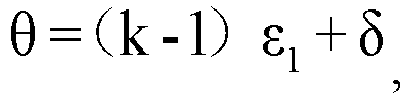
ε 1 is the vertical angular resolution of thefirst radar component 201, and δ is the divergence angle of the laser beam. For example, if the quantity of scanning lines of thefirst radar component 201 is 4, the vertical field of view of thefirst radar component 201 is θ = 3ε1 + δ. - The horizontal angular resolution ε 2 refers to an angle corresponding to a minimum distance that can be resolved by the
first radar component 201 in the horizontal direction. In an example in which themulti-line laser radar 20 is applied to the field of the intelligent transportation technologies, a minimum distance between two adjacent vehicles is not less than 100 meters, and a body width of a small car ranges from 1.5 meters to 2 meters. To detect a small car 100 meters away, the horizontal angular resolution of thefirst radar component 201 is ε 2 = tan-1 (1.5/100) = 0.86°. Therefore, to meet a detection requirement in the field of the intelligent transportation technologies, the horizontal angular resolution ε 2 of thefirst radar component 201 should be less than 0.86°. The horizontal angular resolution ε 2 of thefirst radar component 201 should meet the following formula:
N is a frequency at which asingle laser 21 emits a laser beam, and K is a rotation frequency of thescanning rotating mirror 23. In other words, the horizontal angular resolution ε 2 of thefirst radar component 201 is determined according to both a frequency at which asingle laser 21 emits a laser beam and the rotation frequency of thescanning rotating mirror 23. The frequency at which thesingle laser 21 emits a laser beam and the rotation frequency of thescanning rotating mirror 23 may be properly set, to enable the horizontal angular resolution ε 2 of thefirst radar component 201 to be less than 0.86°. For example, if N is 20 KHz, and K is 20 Hz, the horizontal angular resolution ε 2 of thefirst radar component 201 is 0.36°, and can meet the detection requirement in the field of the intelligent transportation technologies. - In this embodiment of this application, when the
multi-line laser radar 20 is in a working state, the rotation axis always rotates based on the preset rotation period. The laser beams emitted by then lasers 21 pass through the noptical fibers 25 and are exported to theoptical collimating unit 22. The n laser beams collimated by theoptical collimating unit 22 are incident on a reflector directly facing theoptical collimating unit 22 in thescanning rotating mirror 23, and the reflector reflects the collimated n laser beams to the detection area. Because the rotation axis of thescanning rotating mirror 23 always rotates, a reflector on which the collimated n laser beams are incident and a position on which the collimated n laser beams are incident on the reflector change in real time, and irradiated positions of the n laser beams reflected by the reflector in the detection area change cyclically, so as to achieve an effect of laser scanning. If at least two reflectors in the m reflectors have different reflection angles for a same laser beam, thefirst radar component 201 can implement at least 2n-line scanning. If the m reflectors with different reflection angles have different reflection angles for a same laser beam, thefirst radar component 201 can implement (m x n)-line scanning. It should be additionally noted that, when themulti-line laser radar 20 includes a plurality of radar components, the plurality of radar components may share a same optical collimating unit, or each radar component may have an independent optical collimating unit. Similarly, the plurality of radar components may share a same scanning rotating mirror, or each radar component may have an independent scanning rotating mirror. - In conclusion, according to the technical solutions in this embodiment of this application, the multi-line laser radar includes the first radar component that uses a "multiple transmit and single receive" structure, where only one detector is disposed in the first radar component, and a quantity of detectors is reduced as much as possible on a premise of implementing multi-line scanning, so as to reduce a signal crosstalk between detectors. Therefore, working performance of the multi-line laser radar can be improved, and hardware costs of the multi-line laser radar can be reduced. In addition, the scanning rotating mirror includes at least two reflectors that have different reflection angles for a same laser beam, so that one laser can implement at least two-line scanning, and a quantity of scanning lines of the multi-line laser radar can be increased without increasing a quantity of lasers.
- The following embodiment describes a four-line laser radar. The four-line laser radar may be applied to the field of intelligent transportation technologies. For example, the four-line laser radar may be installed on a bumper at a head of a vehicle, so as to implement detection and scanning of an obstacle in front of the vehicle.
- With reference to
FIG. 3 , the four-line laser radar 30 includes afirst radar component 301, where thefirst radar component 301 includes two lasers (which are respectively afirst laser 311 and a second laser 312), two optical fibers (which are respectively a firstoptical fiber 313 and a second optical fiber 314), anoptical collimating unit 315, ascanning rotating mirror 321, and adetector 331. The lasers, the optical fibers, and theoptical collimating unit 315 form a logical laser emitting unit of thefirst radar component 301. The scanningrotating mirror 321 is a logical beam scanning unit of thefirst radar component 301. Thedetector 331 is a logical echo detection unit of thefirst radar component 301. - An emitting end of the
first laser 311 is connected to a light inlet of the firstoptical fiber 313, and an emitting end of thesecond laser 312 is connected to a light inlet of the secondoptical fiber 314. Both thefirst laser 311 and thesecond laser 312 are configured to emit a laser beam to theoptical collimating unit 315. Thefirst laser 311 and thesecond laser 312 work in a time-division mode. - The laser beam emitted by the
first laser 311 is exported to theoptical collimating unit 315 through the firstoptical fiber 313, and the laser beam emitted by thesecond laser 312 is exported to theoptical collimating unit 315 through the secondoptical fiber 314. Light outlets of the firstoptical fiber 313 and the secondoptical fiber 314 both directly face theoptical collimating unit 315. Light outlet points of the firstoptical fiber 313 and the secondoptical fiber 314 are both located on a focal plane of theoptical collimating unit 315, and a fiber core spacing d between the firstoptical fiber 313 and the secondoptical fiber 314 is:
f is a focal length of theoptical collimating unit 315, and ε 1 is a vertical angular resolution of thefirst radar component 301. - The
optical collimating unit 315 is configured to collimate the laser beam emitted by thefirst laser 311 and the laser beam emitted by thesecond laser 312, and the collimated laser beams are incident on thescanning rotating mirror 321. - The scanning
rotating mirror 321 includes arotation axis 3213, and a first reflector 3211 and asecond reflector 3212 that rotate around therotation axis 3213, where an included angle between a normal line of a plane on which the first reflector 3211 is located and a straight line on which therotation axis 3213 is located is 90 degrees, and an included angle between a normal line of a plane on which thesecond reflector 3212 is located and the straight line on which therotation axis 3213 is located is (90 - ε1). A rotation plane of therotation axis 3213 is perpendicular to an arrangement direction of the laser beams, and the arrangement direction of the laser beams is a vertical direction. Both the first reflector 3211 and thesecond reflector 3212 are configured to reflect a laser beam, and the first reflector 3211 and thesecond reflector 3212 have different reflection directions for a same laser beam. -
FIG. 4 is a schematic diagram of thescanning rotating mirror 321 according to an example embodiment of this application. An included angle between the first reflector 3211 and thesecond reflector 3212 is ε1. An included angle between a normal line of a plane on which the first reflector 3211 is located and a straight line on which therotation axis 3213 is located is 90°. An included angle between a normal line of a plane on which thesecond reflector 3212 is located and the straight line on which therotation axis 3213 is located is (90° - ε1). - The
detector 331 is configured to receive an echo signal of a laser beam. Thedetector 331 and theoptical collimating unit 315 are located on a same side, and thedetector 331 is disposed opposite to thescanning rotating mirror 321. A receiving field of view ϕ of thedetector 331 is:
σ is a preset tolerance factor.FIG. 5 is a schematic diagram of the receiving field of view ϕ of thedetector 331 of the four-line laser radar 30 according to an example embodiment of this application. A laser beam emitted by thefirst laser 311 is exported to theoptical collimating unit 315 through the firstoptical fiber 313, and a laser beam emitted by thesecond laser 312 is exported to theoptical collimating unit 315 through the secondoptical fiber 314. An included angle formed when the two laser beams are emitted after being collimated by the optical collimating unit is ε1, a divergence angle of the laser beam is δ, and a receiving angle of view ϕ of thedetector 331 should be slightly greater than (ε1 + δ). - A vertical field of view θ of the
first radar component 301 is:
ε1 is a vertical angular resolution of thefirst radar component 301, and δ is the divergence angle of the laser beam.FIG. 6 is a schematic diagram of the vertical field of view θ of thefirst radar component 301 according to an example embodiment of this application. An included angle between every two laser beams is ε1, and a divergence angle of the laser beam is δ. In this case, a vertical field of view of the four-line laser radar 30 is θ = 3ε1 + δ. - The following describes an operating principle of the
first radar component 301 with reference toFIG. 7 and FIG. 8 . When thefirst radar component 301 is in a working state, the first reflector 3211 and thesecond reflector 3212 of thescanning rotating mirror 321 always rotate around therotation axis 3213 based on a preset rotation period. -
FIG. 7 is an operating principle diagram of implementing, by thefirst radar component 301, two-line scanning in a first half rotation period (that is, 0° to 180°) of thescanning rotating mirror 321 according to an example embodiment of this application. Laser beams emitted by thefirst laser 311 and thesecond laser 312 are successively incident on theoptical collimating unit 315, and the two laser beams are collimated by theoptical collimating unit 315 and then are incident on thesecond reflector 3212 of the scanning rotating mirror, and thesecond reflector 3212 reflects the two laser beams to a front of thefirst radar component 301, so as to implement two-line scanning at an upper layer. If a laser beam reflected by thesecond reflector 3212 detects, through scanning, an obstacle in front, the detector receives an echo signal of the laser beam. -
FIG. 8 is an operating principle diagram of implementing, by thefirst radar component 301, two-line scanning in a second half rotation period (that is, 180° to 360°) of thescanning rotating mirror 321 according to an example embodiment of this application. In this embodiment, laser beams emitted by thefirst laser 311 and thesecond laser 312 are successively incident on theoptical collimating unit 315, the two laser beams are collimated by theoptical collimating unit 315 and then are incident on the first reflector 3211 of the scanning rotating mirror, and the first reflector 3211 reflects the two laser beams to a front of thefirst radar component 301, so as to implement two-line scanning at a lower layer. If a laser beam reflected by the first reflector 3211 detects, through scanning, an obstacle in front, the detector receives an echo signal of the laser beam. - It should be understood the term "multi" refers to two or more than two in this specification. The term "and/or" describes an association relationship for describing associated objects, and represents that three relationships may exist. For example, A and/or B may represent the following three cases: Only A exists, both A and B exist, and only B exists. A character "/" usually indicates an "or" relationship between the associated objects. "First", "second" and similar terms used in this specification do not represent any sequence, quantity, or importance, but are only used to distinguish different objects.
- The implementations described above further describe the objectives, technical solutions, and beneficial effects of the embodiments of this application in detail. It should be understood that the foregoing descriptions are merely example implementations of the embodiments of this application, but are not used to limit a protection scope of the embodiments of this application. Any modification, equivalent replacement, improvement, or the like made based on the technical solutions of the embodiments of this application shall fall within the protection scope of the embodiments of this application.
Claims (10)
- A multi-line laser radar, wherein the multi-line laser radar comprises a first radar component, and the first radar component comprises: n lasers, an optical collimating unit, a scanning rotating mirror, and a detector, wherein n is an integer greater than 1;
each laser of the n lasers is configured to emit one laser beam to the optical collimating unit;
the optical collimating unit is configured to collimate the n laser beams, and the collimated n laser beams are incident on a target reflector of the scanning rotating mirror, wherein the scanning rotating mirror comprises a rotation axis and m reflectors rotating around the rotation axis, a rotation plane of the rotation axis is perpendicular to an arrangement direction of the collimated n laser beams, the target reflector is a reflector that is in the m reflectors and that is currently rotated to a position opposite to an emergent direction of the collimated n laser beams, and m is an integer greater than 1;
the target reflector is configured to reflect the received collimated n laser beams, wherein the reflected n laser beams are incident on a detection area of the first radar component, and at least two reflectors existing in the m reflectors have different reflection angles for a same laser beam; and
the detector is configured to receive echo signals of the reflected n laser beams in the detection area. - The multi-line laser radar according to claim 1, wherein different reflectors in the m reflectors have different reflection angles for a same laser beam.
- The multi-line laser radar according to claim 2, wherein an included angle between a normal line of a plane on which an ith reflector of the m reflectors is located and a straight line on which the rotation axis is located is α + (i-1) γ, wherein 0°< α ≤90°, γ= (n-1) ε 1, ε 1 is a vertical angular resolution of the first radar component, and i is a positive integer less than or equal to m.
- The multi-line laser radar according to any one of claims 1 to 3, wherein the first radar component further comprises: n optical fibers, and the n lasers are in a one-to-one correspondence with the n optical fibers; and
the optical fiber is configured to export the laser beam emitted by the laser to the optical collimating unit. - The multi-line laser radar according to claim 4, wherein a light outlet point of the optical fiber is located on a focal plane of the optical collimating unit.
- The multi-line laser radar according to claim 4, wherein a fiber core spacing d between two adjacent optical fibers in the n optical fibers is:

f is a focal length of the optical collimating unit, and ε 1 is the vertical angular resolution of the first radar component. - The multi-line laser radar according to any one of claims 1 to 6, wherein a receiving field of view ϕ of the detector is:

σ is a preset tolerance factor, ε 1 is the vertical angular resolution of the first radar component, and δ is a divergence angle of the laser beam. - The multi-line laser radar according to any one of claims 1 to 7, wherein a quantity of scanning lines of the first radar component is K, and a vertical field of view θ of the first radar component is:

ε1 is a vertical angular resolution of the first radar component, and δ is a divergence angle of the laser beam. - The multi-line laser radar according to any one of claims 1 to 7, wherein all the lasers work in a time-division mode.
- The multi-line laser radar according to any one of claims 1 to 9, wherein an arrangement direction of the collimated n laser beams is a vertical direction.
Applications Claiming Priority (2)
| Application Number | Priority Date | Filing Date | Title |
|---|---|---|---|
| CN201711469783.8A CN108061904B (en) | 2017-12-29 | 2017-12-29 | Multi-line LiDAR |
| PCT/CN2018/125305 WO2019129259A1 (en) | 2017-12-29 | 2018-12-29 | Multi-line laser radar |
Publications (3)
| Publication Number | Publication Date |
|---|---|
| EP3719540A1 true EP3719540A1 (en) | 2020-10-07 |
| EP3719540A4 EP3719540A4 (en) | 2021-01-06 |
| EP3719540B1 EP3719540B1 (en) | 2025-12-03 |
Family
ID=62140810
Family Applications (1)
| Application Number | Title | Priority Date | Filing Date |
|---|---|---|---|
| EP18895823.5A Active EP3719540B1 (en) | 2017-12-29 | 2018-12-29 | Multi-line laser radar |
Country Status (4)
| Country | Link |
|---|---|
| US (1) | US11513193B2 (en) |
| EP (1) | EP3719540B1 (en) |
| CN (1) | CN108061904B (en) |
| WO (1) | WO2019129259A1 (en) |
Cited By (1)
| Publication number | Priority date | Publication date | Assignee | Title |
|---|---|---|---|---|
| EP4306994A4 (en) * | 2021-03-29 | 2024-08-28 | Huawei Technologies Co., Ltd. | LASER EMISSION METHOD AND APPARATUS, DETECTION APPARATUS AND MOBILE PLATFORM |
Families Citing this family (65)
| Publication number | Priority date | Publication date | Assignee | Title |
|---|---|---|---|---|
| CN108061904B (en) * | 2017-12-29 | 2020-12-22 | 华为技术有限公司 | Multi-line LiDAR |
| US10429495B1 (en) | 2018-04-03 | 2019-10-01 | Hesai Photonics Technology Co., Ltd. | Lidar system and method |
| WO2019237581A1 (en) * | 2018-06-13 | 2019-12-19 | Hesai Photonics Technology Co., Ltd. | Lidar systems and methods |
| CN109031345A (en) * | 2018-06-13 | 2018-12-18 | 北京经纬恒润科技有限公司 | A kind of MEMS micromirror scanning laser radar system and its scan method |
| EP4685520A3 (en) * | 2018-08-10 | 2026-04-01 | Aurora Operations, Inc. | Method and system for scanning of coherent lidar with fan of collimated beams |
| CN108627813B (en) * | 2018-08-13 | 2021-10-15 | 北京经纬恒润科技股份有限公司 | a lidar |
| CN108761427B (en) * | 2018-09-10 | 2024-01-23 | 成都英鑫光电科技有限公司 | Distributed laser radar and automatic driving system |
| CN110333497A (en) * | 2018-09-18 | 2019-10-15 | 深圳市速腾聚创科技有限公司 | A multi-line lidar system |
| US20200103504A1 (en) * | 2018-10-02 | 2020-04-02 | GM Global Technology Operations LLC | Multiple photonic chip lidar system architecture |
| CN109613515B (en) * | 2018-11-16 | 2022-04-01 | 上海禾赛科技有限公司 | Laser radar system |
| CN109597050B (en) * | 2018-11-16 | 2021-10-08 | 上海禾赛科技有限公司 | Laser radar |
| CN110231606B (en) * | 2018-11-27 | 2022-10-11 | 蔚来控股有限公司 | Laser scanning device and laser radar device including the same |
| CN111308441B (en) * | 2018-12-12 | 2024-06-18 | 宁波舜宇车载光学技术有限公司 | Laser radar transmitting device and assembling method |
| DE102018222416B4 (en) * | 2018-12-20 | 2023-01-26 | Robert Bosch Gmbh | Assembly for a LiDAR sensor and LiDAR sensor |
| CN111381239B (en) * | 2018-12-29 | 2022-08-19 | 华为技术有限公司 | A laser measurement module and lidar |
| WO2020142878A1 (en) * | 2019-01-07 | 2020-07-16 | 深圳市大疆创新科技有限公司 | Ranging device and mobile platform |
| EP3910371A4 (en) | 2019-01-09 | 2022-02-23 | SZ DJI Technology Co., Ltd. | SCANNING MODULE, DISTANCE MEASURING DEVICE AND MOBILE PLATFORM |
| WO2020142965A1 (en) * | 2019-01-09 | 2020-07-16 | 深圳市大疆创新科技有限公司 | Scanning module, distance measurement device, and movable platform |
| CN111610506A (en) * | 2019-02-22 | 2020-09-01 | 宁波舜宇车载光学技术有限公司 | Multi-point scanning lidar and its detection method |
| CN111610509B (en) * | 2019-02-26 | 2024-11-05 | 深圳市速腾聚创科技有限公司 | Multi-line LiDAR |
| CN109917420B (en) * | 2019-02-27 | 2024-09-06 | 科沃斯商用机器人有限公司 | Automatic walking device and robot |
| CN110068831A (en) * | 2019-04-02 | 2019-07-30 | 深圳市速腾聚创科技有限公司 | Glisten radar and its emitter and detection method |
| CN111830531A (en) * | 2019-04-12 | 2020-10-27 | 华为技术有限公司 | Light Scanning Components and Lidar |
| CN112034486B (en) * | 2019-05-17 | 2022-08-26 | 华为技术有限公司 | Laser radar and control method of laser radar |
| CN112034478A (en) * | 2019-06-03 | 2020-12-04 | 北醒(北京)光子科技有限公司 | Laser radar and ranging method thereof |
| CN110208773A (en) * | 2019-06-11 | 2019-09-06 | 深圳市镭神智能系统有限公司 | Multi-line laser radar |
| CN110389354B (en) * | 2019-07-19 | 2023-04-25 | 深圳市镭神智能系统有限公司 | A multi-line laser radar and its driving method |
| CN110346811B (en) * | 2019-08-08 | 2022-05-06 | 上海禾赛科技有限公司 | Laser radar and detection device thereof |
| WO2021035428A1 (en) * | 2019-08-23 | 2021-03-04 | 深圳市速腾聚创科技有限公司 | Laser radar and automatic driving equipment |
| WO2021035427A1 (en) * | 2019-08-23 | 2021-03-04 | 深圳市速腾聚创科技有限公司 | Lidar and autonomous driving device |
| CN112558105A (en) * | 2019-09-26 | 2021-03-26 | 深圳市速腾聚创科技有限公司 | Laser radar system and control method of laser radar system |
| CN110531371A (en) * | 2019-09-27 | 2019-12-03 | 无锡流深光电科技有限公司 | A kind of laser radar and laser distance measurement method |
| CN110940290A (en) * | 2019-11-20 | 2020-03-31 | 洛伦兹(北京)科技有限公司 | Laser Transceiver Scanner and Coaxial Transceiver Imaging Device |
| CN110940289A (en) * | 2019-11-20 | 2020-03-31 | 洛伦兹(北京)科技有限公司 | Laser Transceiver Scanner and Coaxial Transceiver Imaging Device |
| WO2021138774A1 (en) * | 2020-01-06 | 2021-07-15 | 深圳市大疆创新科技有限公司 | Multi-line laser module, laser radar, and movable platform |
| CN113552578A (en) * | 2020-04-03 | 2021-10-26 | 上海禾赛科技有限公司 | Lidar and method for detecting objects using the same |
| CN118915078A (en) * | 2020-04-17 | 2024-11-08 | 上海禾赛科技有限公司 | Laser radar and method for detecting target object by using same |
| KR102857675B1 (en) * | 2020-06-11 | 2025-09-10 | 주식회사 케이티 | Apparatus for LIDAR |
| DE102020208127A1 (en) * | 2020-06-30 | 2021-12-30 | Robert Bosch Gesellschaft mit beschränkter Haftung | Lidar arrangement |
| WO2022006752A1 (en) * | 2020-07-07 | 2022-01-13 | 深圳市速腾聚创科技有限公司 | Laser receiving apparatus, laser radar, and smart sensing device |
| CN111983585A (en) * | 2020-07-17 | 2020-11-24 | 中国工程物理研究院应用电子学研究所 | A Polygonal Mirror Scanning Control System for Multi-Single Mirror Lidar |
| CN111983584A (en) * | 2020-07-17 | 2020-11-24 | 中国工程物理研究院应用电子学研究所 | MEMS galvanometer scanning control system of multi-shot mirror laser radar |
| CN112099053A (en) * | 2020-08-21 | 2020-12-18 | 上海禾赛光电科技有限公司 | Laser radar detection method, laser radar and vehicle system comprising laser radar |
| CN112379670B (en) * | 2020-11-10 | 2024-09-24 | 京东科技信息技术有限公司 | Laser radar viewing angle extension device for robot and robot |
| CN112285673B (en) * | 2020-11-16 | 2025-05-02 | 北京未感科技有限公司 | A laser radar and intelligent sensing device |
| DE102020214464A1 (en) * | 2020-11-18 | 2022-05-19 | Robert Bosch Gesellschaft mit beschränkter Haftung | lidar sensor |
| WO2022147652A1 (en) * | 2021-01-05 | 2022-07-14 | 深圳市速腾聚创科技有限公司 | Laser radar and device having laser radar |
| CN112799084B (en) * | 2021-02-01 | 2025-03-11 | 深圳市威睿晶科电子有限公司 | Dual-line LiDAR |
| CN113508310B (en) * | 2021-03-24 | 2022-10-11 | 华为技术有限公司 | Detection method and device |
| CN115189224B (en) * | 2021-04-01 | 2025-09-30 | 上海禾赛科技有限公司 | Laser and laser radar including the laser |
| CN113567956B (en) * | 2021-04-09 | 2023-01-13 | 华为技术有限公司 | Detection device and control method thereof |
| CN121385843A (en) * | 2021-04-30 | 2026-01-23 | 上海禾赛科技有限公司 | Optical detection devices and vehicles |
| CN113391294B (en) * | 2021-06-18 | 2021-12-31 | 特斯联科技集团有限公司 | Multi-line laser radar constraint adjusting system and detection method |
| CN113721250B (en) * | 2021-08-30 | 2024-11-15 | 中国电子科技集团公司第四十四研究所 | A discrete field of view laser short-range detection front-end device |
| CN121956029A (en) * | 2021-09-24 | 2026-05-01 | 探维科技(湖州)有限公司 | A lidar system |
| CN114488089A (en) * | 2021-12-30 | 2022-05-13 | 武汉万集光电技术有限公司 | Multi-line laser radar |
| CN114089311B (en) * | 2022-01-19 | 2022-05-17 | 探维科技(北京)有限公司 | Laser radar system |
| JP7785576B2 (en) * | 2022-03-18 | 2025-12-15 | 株式会社東芝 | LiDAR device and LiDAR device control method |
| CN114677315B (en) | 2022-04-11 | 2022-11-29 | 探维科技(北京)有限公司 | Image fusion method, device, equipment and medium based on image and laser point cloud |
| CN115840212A (en) * | 2022-07-26 | 2023-03-24 | 深圳市速腾聚创科技有限公司 | Laser radar and storage medium |
| CN119546976A (en) * | 2022-08-29 | 2025-02-28 | 深圳引望智能技术有限公司 | A detection device and terminal equipment |
| CN117665836A (en) * | 2022-08-31 | 2024-03-08 | 华为技术有限公司 | Lidar, electronic equipment and vehicles |
| CN115685217A (en) * | 2022-09-21 | 2023-02-03 | 苏州岭纬智能科技有限公司 | A LiDAR Based on Polyhedral Structure |
| CN117092658B (en) * | 2023-10-20 | 2023-12-26 | 徐州瑞控机电科技有限公司 | Target intelligent detection positioning method based on laser radar |
| WO2025260217A1 (en) * | 2024-06-17 | 2025-12-26 | 深圳引望智能技术有限公司 | Detection device, lidar and terminal |
Family Cites Families (17)
| Publication number | Priority date | Publication date | Assignee | Title |
|---|---|---|---|---|
| DE10227299A1 (en) | 2002-06-19 | 2004-01-08 | Sick Ibeo Gmbh | Scanner for optical object detection |
| WO2007071032A1 (en) * | 2005-12-19 | 2007-06-28 | Institut National D'optique | Object-detecting lighting system and method |
| JP2008094025A (en) * | 2006-10-13 | 2008-04-24 | Canon Inc | Frequency modulator |
| JP5729358B2 (en) * | 2011-09-22 | 2015-06-03 | 株式会社リコー | Optical beam scanner and laser radar unit |
| US9291816B2 (en) * | 2012-03-23 | 2016-03-22 | Panasonic intellectual property Management co., Ltd | Scanning mirror and scanning image display device |
| JP6111617B2 (en) * | 2012-07-03 | 2017-04-12 | 株式会社リコー | Laser radar equipment |
| JP2014020889A (en) * | 2012-07-18 | 2014-02-03 | Ricoh Co Ltd | Object detection device |
| JP2014052366A (en) * | 2012-08-06 | 2014-03-20 | Ricoh Co Ltd | Optical measurement instrument and vehicle |
| JP6103179B2 (en) * | 2012-09-13 | 2017-03-29 | 株式会社リコー | Distance measuring device |
| US9086273B1 (en) * | 2013-03-08 | 2015-07-21 | Google Inc. | Microrod compression of laser beam in combination with transmit lens |
| US8836922B1 (en) | 2013-08-20 | 2014-09-16 | Google Inc. | Devices and methods for a rotating LIDAR platform with a shared transmit/receive path |
| US9831630B2 (en) * | 2014-02-06 | 2017-11-28 | GM Global Technology Operations LLC | Low cost small size LiDAR for automotive |
| JP6667213B2 (en) * | 2014-07-16 | 2020-03-18 | キヤノン株式会社 | Optical scanning apparatus, image forming apparatus, and method of assembling optical scanning apparatus |
| JP6671629B2 (en) * | 2015-03-18 | 2020-03-25 | 株式会社リコー | Object detection device, sensing device, and mobile device |
| CN105785343A (en) * | 2016-04-29 | 2016-07-20 | 中国科学院电子学研究所 | Spacial multi-beam laser emitter, multichannel receiving apparatus and detection apparatus |
| CN106371085A (en) * | 2016-10-27 | 2017-02-01 | 上海博未传感技术有限公司 | Laser radar system based on optical fiber array |
| CN108061904B (en) * | 2017-12-29 | 2020-12-22 | 华为技术有限公司 | Multi-line LiDAR |
-
2017
- 2017-12-29 CN CN201711469783.8A patent/CN108061904B/en active Active
-
2018
- 2018-12-29 WO PCT/CN2018/125305 patent/WO2019129259A1/en not_active Ceased
- 2018-12-29 EP EP18895823.5A patent/EP3719540B1/en active Active
-
2020
- 2020-06-29 US US16/915,816 patent/US11513193B2/en active Active
Cited By (1)
| Publication number | Priority date | Publication date | Assignee | Title |
|---|---|---|---|---|
| EP4306994A4 (en) * | 2021-03-29 | 2024-08-28 | Huawei Technologies Co., Ltd. | LASER EMISSION METHOD AND APPARATUS, DETECTION APPARATUS AND MOBILE PLATFORM |
Also Published As
| Publication number | Publication date |
|---|---|
| US20200333444A1 (en) | 2020-10-22 |
| CN108061904A (en) | 2018-05-22 |
| CN108061904B (en) | 2020-12-22 |
| US11513193B2 (en) | 2022-11-29 |
| WO2019129259A1 (en) | 2019-07-04 |
| EP3719540A4 (en) | 2021-01-06 |
| EP3719540B1 (en) | 2025-12-03 |
Similar Documents
| Publication | Publication Date | Title |
|---|---|---|
| US11513193B2 (en) | Multi-line laser radar | |
| US12055661B2 (en) | Lidar system and method | |
| CN214795200U (en) | Window for laser radar and laser radar | |
| EP3859377B1 (en) | Distance detection device | |
| CN112219130B (en) | a distance measuring device | |
| CN210015229U (en) | Distance detection device | |
| CN108445467A (en) | A kind of scanning laser radar system | |
| CN211236225U (en) | Large-view-field laser radar optical-mechanical system | |
| CN209356678U (en) | Range unit | |
| WO2020207439A1 (en) | Optical scanning assembly and laser radar | |
| JPWO2016056543A1 (en) | Scanning optical system and radar | |
| CN208737000U (en) | A kind of four sides revolving mirror laser radar | |
| US20240003739A1 (en) | Optical receiving device and optical sensing device | |
| CN111045018B (en) | Optical device and positioning system of robot | |
| WO2016056541A1 (en) | Scanning optical system and radar | |
| CN210690805U (en) | Multi-line laser radar | |
| CN216117996U (en) | Optical path deflection module and application thereof | |
| JP2017125765A (en) | Object detection device | |
| CN120722324A (en) | FMCW laser radar and mobile equipment | |
| CN217360285U (en) | Scanning device | |
| CN115267800B (en) | Window for laser radar and laser radar | |
| CN119270239A (en) | Extinction tube and laser radar | |
| CN114690148A (en) | Optical system of laser radar and laser radar | |
| CN218848327U (en) | Optical fiber fixing structure, laser emitting device and laser radar | |
| CN113030912A (en) | Laser radar system based on scanning galvanometer |
Legal Events
| Date | Code | Title | Description |
|---|---|---|---|
| STAA | Information on the status of an ep patent application or granted ep patent |
Free format text: STATUS: THE INTERNATIONAL PUBLICATION HAS BEEN MADE |
|
| PUAI | Public reference made under article 153(3) epc to a published international application that has entered the european phase |
Free format text: ORIGINAL CODE: 0009012 |
|
| STAA | Information on the status of an ep patent application or granted ep patent |
Free format text: STATUS: REQUEST FOR EXAMINATION WAS MADE |
|
| 17P | Request for examination filed |
Effective date: 20200702 |
|
| AK | Designated contracting states |
Kind code of ref document: A1 Designated state(s): AL AT BE BG CH CY CZ DE DK EE ES FI FR GB GR HR HU IE IS IT LI LT LU LV MC MK MT NL NO PL PT RO RS SE SI SK SM TR |
|
| AX | Request for extension of the european patent |
Extension state: BA ME |
|
| A4 | Supplementary search report drawn up and despatched |
Effective date: 20201203 |
|
| RIC1 | Information provided on ipc code assigned before grant |
Ipc: G02B 26/12 20060101ALI20201127BHEP Ipc: G01S 7/481 20060101ALI20201127BHEP Ipc: G01S 17/93 20200101AFI20201127BHEP |
|
| DAV | Request for validation of the european patent (deleted) | ||
| DAX | Request for extension of the european patent (deleted) | ||
| STAA | Information on the status of an ep patent application or granted ep patent |
Free format text: STATUS: EXAMINATION IS IN PROGRESS |
|
| 17Q | First examination report despatched |
Effective date: 20220614 |
|
| RAP1 | Party data changed (applicant data changed or rights of an application transferred) |
Owner name: SHENZHEN YINWANG INTELLIGENTTECHNOLOGIES CO., LTD. |
|
| GRAP | Despatch of communication of intention to grant a patent |
Free format text: ORIGINAL CODE: EPIDOSNIGR1 |
|
| STAA | Information on the status of an ep patent application or granted ep patent |
Free format text: STATUS: GRANT OF PATENT IS INTENDED |
|
| INTG | Intention to grant announced |
Effective date: 20250709 |
|
| GRAS | Grant fee paid |
Free format text: ORIGINAL CODE: EPIDOSNIGR3 |
|
| GRAA | (expected) grant |
Free format text: ORIGINAL CODE: 0009210 |
|
| STAA | Information on the status of an ep patent application or granted ep patent |
Free format text: STATUS: THE PATENT HAS BEEN GRANTED |
|
| AK | Designated contracting states |
Kind code of ref document: B1 Designated state(s): AL AT BE BG CH CY CZ DE DK EE ES FI FR GB GR HR HU IE IS IT LI LT LU LV MC MK MT NL NO PL PT RO RS SE SI SK SM TR |
|
| REG | Reference to a national code |
Ref country code: CH Ref legal event code: F10 Free format text: ST27 STATUS EVENT CODE: U-0-0-F10-F00 (AS PROVIDED BY THE NATIONAL OFFICE) Effective date: 20251203 Ref country code: GB Ref legal event code: FG4D |
|
| P01 | Opt-out of the competence of the unified patent court (upc) registered |
Free format text: CASE NUMBER: UPC_APP_0011844_3719540/2025 Effective date: 20251031 |
|
| REG | Reference to a national code |
Ref country code: DE Ref legal event code: R096 Ref document number: 602018087715 Country of ref document: DE |
|
| REG | Reference to a national code |
Ref country code: IE Ref legal event code: FG4D |
|
| PGFP | Annual fee paid to national office [announced via postgrant information from national office to epo] |
Ref country code: DE Payment date: 20251210 Year of fee payment: 8 |
|
| PGFP | Annual fee paid to national office [announced via postgrant information from national office to epo] |
Ref country code: GB Payment date: 20251211 Year of fee payment: 8 |
|
| REG | Reference to a national code |
Ref country code: NL Ref legal event code: MP Effective date: 20251203 |
|
| PG25 | Lapsed in a contracting state [announced via postgrant information from national office to epo] |
Ref country code: ES Free format text: LAPSE BECAUSE OF FAILURE TO SUBMIT A TRANSLATION OF THE DESCRIPTION OR TO PAY THE FEE WITHIN THE PRESCRIBED TIME-LIMIT Effective date: 20251203 |
|
| REG | Reference to a national code |
Ref country code: LT Ref legal event code: MG9D |
|
| PG25 | Lapsed in a contracting state [announced via postgrant information from national office to epo] |
Ref country code: NO Free format text: LAPSE BECAUSE OF FAILURE TO SUBMIT A TRANSLATION OF THE DESCRIPTION OR TO PAY THE FEE WITHIN THE PRESCRIBED TIME-LIMIT Effective date: 20260303 |
|
| PG25 | Lapsed in a contracting state [announced via postgrant information from national office to epo] |
Ref country code: FI Free format text: LAPSE BECAUSE OF FAILURE TO SUBMIT A TRANSLATION OF THE DESCRIPTION OR TO PAY THE FEE WITHIN THE PRESCRIBED TIME-LIMIT Effective date: 20251203 Ref country code: HR Free format text: LAPSE BECAUSE OF FAILURE TO SUBMIT A TRANSLATION OF THE DESCRIPTION OR TO PAY THE FEE WITHIN THE PRESCRIBED TIME-LIMIT Effective date: 20251203 |
|
| PG25 | Lapsed in a contracting state [announced via postgrant information from national office to epo] |
Ref country code: RS Free format text: LAPSE BECAUSE OF FAILURE TO SUBMIT A TRANSLATION OF THE DESCRIPTION OR TO PAY THE FEE WITHIN THE PRESCRIBED TIME-LIMIT Effective date: 20260303 |
|
| PG25 | Lapsed in a contracting state [announced via postgrant information from national office to epo] |
Ref country code: PL Free format text: LAPSE BECAUSE OF FAILURE TO SUBMIT A TRANSLATION OF THE DESCRIPTION OR TO PAY THE FEE WITHIN THE PRESCRIBED TIME-LIMIT Effective date: 20251203 |
|
| PG25 | Lapsed in a contracting state [announced via postgrant information from national office to epo] |
Ref country code: LV Free format text: LAPSE BECAUSE OF FAILURE TO SUBMIT A TRANSLATION OF THE DESCRIPTION OR TO PAY THE FEE WITHIN THE PRESCRIBED TIME-LIMIT Effective date: 20251203 |
|
| PG25 | Lapsed in a contracting state [announced via postgrant information from national office to epo] |
Ref country code: BG Free format text: LAPSE BECAUSE OF FAILURE TO SUBMIT A TRANSLATION OF THE DESCRIPTION OR TO PAY THE FEE WITHIN THE PRESCRIBED TIME-LIMIT Effective date: 20251203 |
|
| REG | Reference to a national code |
Ref country code: CH Ref legal event code: W10 Free format text: ST27 STATUS EVENT CODE: U-0-0-W10-W00 (AS PROVIDED BY THE NATIONAL OFFICE) Effective date: 20260507 |