EP3719488A1 - Laser desorption/ionization method and mass spectrometry method - Google Patents
Laser desorption/ionization method and mass spectrometry method Download PDFInfo
- Publication number
- EP3719488A1 EP3719488A1 EP18882884.2A EP18882884A EP3719488A1 EP 3719488 A1 EP3719488 A1 EP 3719488A1 EP 18882884 A EP18882884 A EP 18882884A EP 3719488 A1 EP3719488 A1 EP 3719488A1
- Authority
- EP
- European Patent Office
- Prior art keywords
- sample
- solvent
- support body
- holes
- laser desorption
- Prior art date
- Legal status (The legal status is an assumption and is not a legal conclusion. Google has not performed a legal analysis and makes no representation as to the accuracy of the status listed.)
- Withdrawn
Links
Images






Classifications
-
- H—ELECTRICITY
- H01—ELECTRIC ELEMENTS
- H01J—ELECTRIC DISCHARGE TUBES OR DISCHARGE LAMPS
- H01J49/00—Particle spectrometers or separator tubes
- H01J49/02—Details
- H01J49/04—Arrangements for introducing or extracting samples to be analysed, e.g. vacuum locks; Arrangements for external adjustment of electron- or ion-optical components
- H01J49/0409—Sample holders or containers
- H01J49/0418—Sample holders or containers for laser desorption, e.g. matrix-assisted laser desorption/ionisation [MALDI] plates or surface enhanced laser desorption/ionisation [SELDI] plates
-
- H—ELECTRICITY
- H01—ELECTRIC ELEMENTS
- H01J—ELECTRIC DISCHARGE TUBES OR DISCHARGE LAMPS
- H01J49/00—Particle spectrometers or separator tubes
- H01J49/0027—Methods for using particle spectrometers
- H01J49/0031—Step by step routines describing the use of the apparatus
-
- H—ELECTRICITY
- H01—ELECTRIC ELEMENTS
- H01J—ELECTRIC DISCHARGE TUBES OR DISCHARGE LAMPS
- H01J49/00—Particle spectrometers or separator tubes
- H01J49/02—Details
- H01J49/04—Arrangements for introducing or extracting samples to be analysed, e.g. vacuum locks; Arrangements for external adjustment of electron- or ion-optical components
- H01J49/0431—Arrangements for introducing or extracting samples to be analysed, e.g. vacuum locks; Arrangements for external adjustment of electron- or ion-optical components for liquid samples
-
- H—ELECTRICITY
- H01—ELECTRIC ELEMENTS
- H01J—ELECTRIC DISCHARGE TUBES OR DISCHARGE LAMPS
- H01J49/00—Particle spectrometers or separator tubes
- H01J49/02—Details
- H01J49/06—Electron- or ion-optical arrangements
- H01J49/068—Mounting, supporting, spacing, or insulating electrodes
-
- H—ELECTRICITY
- H01—ELECTRIC ELEMENTS
- H01J—ELECTRIC DISCHARGE TUBES OR DISCHARGE LAMPS
- H01J49/00—Particle spectrometers or separator tubes
- H01J49/02—Details
- H01J49/10—Ion sources; Ion guns
- H01J49/16—Ion sources; Ion guns using surface ionisation, e.g. field-, thermionic- or photo-emission
- H01J49/161—Ion sources; Ion guns using surface ionisation, e.g. field-, thermionic- or photo-emission using photoionisation, e.g. by laser
- H01J49/164—Laser desorption/ionisation, e.g. matrix-assisted laser desorption/ionisation [MALDI]
Definitions
- the present disclosure relates to a laser desorption/ionization method and a mass spectrometry method.
- a matrix-assisted laser desorption/ionization method is known as a method of ionizing a sample such as a biological sample in order to perform mass spectrometry or the like (for example, refer to Patent Literature 1).
- the MALDI is a method of ionizing a sample by adding a low-molecular-weight organic compound referred to as a matrix that absorbs laser beam into the sample, and by irradiating the sample with laser beam. According to such a method, it is possible to ionize a thermally unstable substance or a high-molecular-weight substance in a non-destructive manner (so-called soft ionization).
- SALDI surface-assisted laser desorption/ionization method
- the SALDI is a method of ionizing a sample by dropping the sample onto an ionization substrate having a fine concavo-convex structure on a surface, and by irradiating the sample with laser beam.
- the mass spectrometry In the mass spectrometry, the ionized sample is detected, and the mass spectrometry of the sample is performed on the basis of a detection result thereof. Therefore, in the mass spectrometry, it is desirable to improve a detection intensity (a sensitivity) of the ionized sample.
- an object of the present disclosure is to provide a laser desorption/ionization method and a mass spectrometry method in which in mass spectrometry, a detection intensity of an ionized sample can be improved.
- a laser desorption/ionization method of one aspect of the present disclosure includes: a first step of preparing a sample support body including a substrate on which a plurality of through holes opening to a first surface and a second surface facing each other are formed, and a conductive layer provided on at least the first surface; a second step of introducing a sample and a solvent having refractoriness in a vacuum into the plurality of through holes; and a third step of ionizing a component of the sample by irradiating the first surface with laser beam while applying a voltage to the conductive layer.
- the sample and the solvent are introduced into the plurality of through holes.
- the component of the sample is remained on the first surface side in each of the through holes, along with the solvent.
- energy is transmitted to the component of the sample on the first surface side.
- the component of the sample is ionized.
- the solvent has refractoriness in a vacuum. For this reason, the solvent is more reliably remained on the first surface side, compared to a case where the solvent has volatility in a vacuum. Therefore, the component of the sample is also more reliably remained on the first surface side.
- the component of the sample is more reliably ionized.
- the laser desorption/ionization method in mass spectrometry, it is possible to improve a detection intensity of the ionized sample.
- a mixed liquid of the sample and the solvent may be dropped onto a mounting surface of a mounting portion, and the sample support body may be disposed on the mixed liquid such that the second surface is in contact with the mixed liquid
- the component of the sample in the mixed liquid that is moved to the first surface side from the second surface side through the through hole may be ionized by irradiating the first surface with the laser beam while applying the voltage to the conductive layer.
- the mixed liquid containing the sample is moved to the first surface side from the second surface side through each of the through holes.
- the mixed liquid is remained on the first surface side in each of the through holes.
- the component of the sample is more reliably remained on the first surface side, and is more reliably ionized. Accordingly, in the mass spectrometry, it is possible to improve the detection intensity of the ionized sample.
- the sample support body in the second step, may be mounted on the mounting surface such that the second surface faces the mounting surface of the mounting portion, and the mixed liquid of the sample and the solvent may be dropped into the plurality of through holes from the first surface side, and in the third step, the component of the sample in the mixed liquid that is remained on the first surface side may be ionized by irradiating the first surface with the laser beam while applying the voltage to the conductive layer.
- the mixed liquid containing the sample is moved to the second surface side from the first surface side through each of the through holes, and each of the through holes is filled with the mixed liquid.
- the mixed liquid is remained on the first surface side in each of the through holes.
- the component of the sample is more reliably remained on the first surface side, and is more reliably ionized. Accordingly, in the mass spectrometry, it is possible to improve the detection intensity of the ionized sample.
- the sample in the second step, the sample may be mounted on the mounting surface of the mounting portion, the sample support body may be disposed on the sample such that the second surface is in contact with the sample, and then, the solvent may be introduced into the plurality of through holes, and in the third step, the component of the sample that is mixed with the solvent and is moved to the first surface side from the second surface side through the through hole may be ionized by irradiating the first surface with the laser beam while applying the voltage to the conductive layer, in a state in which the sample is disposed between the mounting portion and the sample support body.
- the solvent is moved to the second surface side from the first surface side through each of the through holes, and is mixed with the component of the sample.
- the component of the sample is mixed with the solvent and is moved to the first surface side from the second surface side through each of the through holes.
- the component of the sample is remained on the first surface side, along with the solvent. Then, as described above, the component of the sample is more reliably remained on the first surface side, and is more reliably ionized. Accordingly, in the mass spectrometry, it is possible to improve the detection intensity of the ionized sample.
- the solvent in the second step, the solvent may be introduced into the plurality of through holes, the sample may be mounted on the mounting surface of the mounting portion, and then, the sample support body may be disposed on the sample such that the second surface is in contact with the sample, and in the third step, the component of the sample that mixed with the solvent and is moved to the first surface side from the second surface side through the through hole may be ionized by irradiating the first surface with the laser beam while applying the voltage to the conductive layer, in a state in which the sample is disposed between the mounting portion and the sample support body.
- the sample support body in which the solvent is introduced into the plurality of through holes is disposed on the sample.
- the component of the sample is mixed with the solvent and is moved to the first surface side from the second surface side through each of the through holes.
- the component of the sample is remained on the first surface side, along with the solvent. Then, as described above, the component of the sample is more reliably remained on the first surface side, and is more reliably ionized. Accordingly, in the mass spectrometry, it is possible to improve the detection intensity of the ionized sample.
- the solvent in the second step, may be dropped into the plurality of through holes from the first surface side. In this case, it is possible to easily introduce the solvent into each of the through holes.
- the solvent in the second step, may be dropped into the plurality of through holes from the first surface side or the second surface side. In this case, it is possible to easily introduce the solvent into each of the through holes.
- the sample support body in the second step, may be dipped in the solvent. In this case, it is possible to easily introduce the solvent into each of the through holes.
- the solvent in the second step, may be introduced into the plurality of through holes in a state of being heated and evaporate. In this case, it is possible to easily introduce the solvent into each of the through holes.
- the sample may be a dry sample.
- the component of the sample is mixed with the solvent and is moved, and thus, even in a case where the sample is the dry sample, it is possible to smoothly move the component of the sample.
- a laser desorption/ionization method of one aspect of the present disclosure includes: a first step of preparing a sample support body including a substrate having conductivity on which a plurality of through holes opening to a first surface and a second surface facing each other are formed; a second step of introducing a sample and a solvent having refractoriness in a vacuum into the plurality of through holes; and a third step of ionizing a component of the sample by irradiating the first surface with laser beam while applying a voltage to the substrate.
- the laser desorption/ionization method it is possible to omit the conductive layer from the sample support body, and to obtain the same effect as that of a case where the sample support body including the conductive layer as described above is used.
- the solvent may be at least one selected from glycerin, diethanol amine, triethanol amine, nitrobenzyl alcohol, nitrophenyl octyl ether, thioglycerol, diethylene glycol, triethylene glycol, tetraethylene glycol, liquid paraffin, sulfolane, dithiothreitol, a mixture of dithiothreitol and thioglycerol, a mixture of dithiothreitol and nitrobenzyl alcohol, and a mixture of dithiothreitol and dithioerythritol.
- glycerin diethanol amine, triethanol amine, nitrobenzyl alcohol, nitrophenyl octyl ether, thioglycerol, diethylene glycol, triethylene glycol, tetraethylene glycol, liquid paraffin, sulfolane, dithiothreitol, a mixture of dithiothreitol and
- a mass spectrometry method of one aspect of the present disclosure includes: each of the steps of the laser desorption/ionization method described above; and a fourth step of detecting the component that is ionized in the third step.
- the mass spectrometry method it is possible to improve the detection intensity of the ionized sample.
- a sample support body 1 includes a substrate 2, a frame 3, and a conductive layer 4.
- the substrate 2 includes a first surface 2a and a second surface 2b facing each other.
- a plurality of through holes 2c are formed on the substrate 2 uniformly (with a homogeneous distribution). Each of the through holes 2c extends along a thickness direction of the substrate 2 (a direction perpendicular to the first surface 2a and the second surface 2b), and opens to the first surface 2a and the second surface 2b.
- the substrate 2 for example, is formed of an insulating material into the shape of a rectangular plate.
- the length of one side of the substrate 2 when seen from the thickness direction of the substrate 2, for example, is approximately several cm, and the thickness of the substrate 2, for example, is approximately 1 ⁇ m to 50 ⁇ m.
- the through hole 2c for example, is approximately in the shape of a circle when seen from the thickness direction of the substrate 2.
- the width of the through hole 2c is 1 nm to 700 nm.
- the width of the through hole 2c indicates the diameter of the through hole 2c in a case where the through hole 2c is approximately in the shape of a circle when seen from the thickness direction of the substrate 2, and indicates the diameter (an effective diameter) of a virtual maximum cylinder falling into the through hole 2c in a case where the through hole 2c is not approximately in the shape of a circle.
- a pitch between the respective through holes 2c is 1 nm to 1000 nm.
- the pitch between the respective through holes 2c indicates a center-to-center distance of the respective circles
- the pitch between the respective through holes 2c indicates a center axis-to-center axis distance of the virtual maximum cylinder falling into the through hole 2c.
- the frame 3 is provided on the first surface 2a of the substrate 2. Specifically, the frame 3 is fixed to the first surface 2a of the substrate 2 by an adhesive layer 5. It is preferable that an adhesive material having less emitted gas (for example, glass with a low melting point, a vacuum adhesive agent, and the like) is used as the material of the adhesive layer 5.
- the frame 3 has approximately the same outer shape as that of the substrate 2 when seen from the thickness direction of the substrate 2.
- An opening 3a is formed in the frame 3. A portion corresponding to the opening 3a in the substrate 2 functions as an effective region R for moving a component of a sample described below to the first surface 2a side.
- the frame 3, for example, is formed into the shape of a rectangular plate by the insulating material.
- the length of one side of the frame 3 when seen from the thickness direction of the substrate 2, for example, is approximately several cm, and the thickness of the frame 3, for example, is less than or equal to 1 mm.
- the opening 3a for example, is in the shape of a circle when seen from the thickness direction of the substrate 2, and in such a case, the diameter of the opening 3a, for example, is approximately several mm to several tens of mm.
- the conductive layer 4 is provided on the first surface 2a of the substrate 2. Specifically, the conductive layer 4 is formed in a region corresponding to the opening 3a of the frame 3 on the first surface 2a of the substrate 2 (that is, a region corresponding to the effective region R), and is continuously (integrally) formed on an inner surface of the opening 3a, and a surface 3b of the frame 3 on a side opposite to the substrate 2. In the effective region R, the conductive layer 4 covers a portion in which the through hole 2c is not formed on the first surface 2a of the substrate 2. That is, in the effective region R, each of the through holes 2c is exposed to the opening 3a.
- the conductive layer 4 is formed of a conductive material. However, it is preferable that a metal having low affinity (reactivity) with respect to a sample S and high conductivity is used as the material of the conductive layer 4, from the following reasons.
- the conductive layer 4 is formed of a metal such as copper (Cu) having high affinity with respect to a sample such as protein
- Cu copper
- the sample in a process of ionizing the sample described below, the sample is ionized in a state where Cu atoms are attached to sample molecules.
- a detection result is shifted in the mass spectrometry method described below as the Cu atoms are attached. Therefore, it is preferable that a metal having low affinity with respect to the sample is used as the material of the conductive layer 4.
- a metal having high conductivity easily and stably applies a constant voltage. For this reason, in a case where the conductive layer 4 is formed of the metal having high conductivity, it is possible to homogeneously apply a voltage to the first surface 2a of the substrate 2 in the effective region R. In addition, there is a tendency that the metal having high conductivity also has high thermal conductivity. For this reason, in a case where the conductive layer 4 is formed of the metal having high conductivity, it is possible to efficiently transfer the energy of laser beam that is applied to the substrate 2 to the sample via the conductive layer 4. Therefore, it is preferable that the metal having high conductivity is used as the material of the conductive layer 4.
- the conductive layer 4 is formed to have a thickness of approximately 1 nm to 350 nm by a plating method, an atomic layer deposition (ALD) method, a vapor deposition method, a sputtering method, and the like.
- ALD atomic layer deposition
- Cr chromium
- Ni nickel
- Ti titanium
- FIG. 3 is a diagram illustrating an enlarged image of the substrate 2 when seen from the thickness direction of the substrate 2.
- a black portion is the through hole 2c
- a white portion is a partition portion between the through holes 2c.
- the plurality of through holes 2c having an approximately constant width are uniformly formed on the substrate 2. It is preferable that an opening rate of the through holes 2c in the effective region R (a ratio of all of the through holes 2c to the effective region R when seen from the thickness direction of the substrate 2) is practically 10% to 80%, and is particularly 60% to 80%.
- the sizes of the plurality of through holes 2c may be uneven with each other, and the plurality of through holes 2c may be partially connected to each other.
- the substrate 2 illustrated in FIG. 3 is an alumina porous film that is formed by performing anodic oxidation with respect to aluminum (Al). Specifically, an anodic oxidation treatment is performed with respect to an Al substrate, and a surface portion that is oxidized is peeled off from the Al substrate, and thus, it is possible to obtain the substrate 2.
- the substrate 2 may be formed by performing anodic oxidation with respect to a valve metal other than Al, such as tantalum (Ta), niobium (Nb), titanium (Ti), hafnium (Hf), zirconium (Zr), zinc (Zn), tungsten (W), bismuth (Bi), and antimony (Sb), or may be formed by performing anodic oxidation with respect to silicon (Si).
- a valve metal other than Al such as tantalum (Ta), niobium (Nb), titanium (Ti), hafnium (Hf), zirconium (Zr), zinc (Zn), tungsten (W), bismuth (Bi), and antimony (Sb)
- a valve metal other than Al such as tantalum (Ta), niobium (Nb), titanium (Ti), hafnium (Hf), zirconium (Zr), zinc (Zn), tungsten (W), bismuth (Bi), and antimony (Sb
- the laser desorption/ionization method and the mass spectrometry method of the first embodiment will be described.
- the through hole 2c, the conductive layer 4, and the adhesive layer 5 in the sample support body 1 are not illustrated.
- a dimensional ratio or the like is different between the sample support body 1 illustrated in FIG. 1 and FIG. 2 and the sample support body 1 illustrated in FIG. 4 to FIG. 6 .
- the sample support body 1 described above is prepared (a first step).
- the sample support body 1 may be prepared by being manufactured by a person who carries out the laser desorption/ionization method and the mass spectrometry method, or may be prepared by being acquired from a manufacturer, a seller, or the like of the sample support body 1.
- the sample that is a mass spectrometry target and a solvent are introduced into the plurality of through holes 2c (a second step).
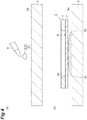
- a mixed liquid 80 of the sample S and a solvent 81 for example, is dropped onto a mounting surface 6a of a glass slide (a mounting portion) 6 by a pipette 8.
- the glass slide 6 is a glass substrate on which a transparent conductive film such as an indium tin oxide (ITO) film is formed, and the surface of the transparent conductive film is the mounting surface 6a.
- ITO indium tin oxide
- the sample support body 1 is disposed on the mixed liquid 80 such that the second surface 2b is in contact with the mixed liquid 80.
- the mixed liquid 80 is disposed in the effective region R when seen from the thickness direction of the substrate 2.
- the mixed liquid 80 is a solution containing the sample S and the solvent 81.
- the sample S for example, is a peptide sample.
- the solvent 81 for example, is an organic solvent.
- the solvent 81 has refractoriness in a vacuum. "Having refractoriness in a vacuum” indicates having refractoriness higher than that of water in a vacuum. That is, “having refractoriness in a vacuum” indicates having less volatility than that of water in a vacuum. “Having refractoriness in a vacuum” indicates that volatility in a vacuum is lower than volatility of water in vacuum.
- the volatility of the solvent 81 is lower than the volatility of water. In a vacuum, the volatility of the solvent 81 is lower than the volatility of water. In the atmosphere, the volatility of the solvent 81 is lower than the volatility of acetone. In a vacuum, the volatility of the solvent 81 is lower than the volatility of acetone. In the atmosphere, the volatility of the solvent 81 is lower than the volatility of acetonitrile. In a vacuum, the volatility of the solvent 81 is lower than the volatility of acetonitrile. In the atmosphere, the solvent 81 is in a liquid form, and has fluidity. In a vacuum, the solvent 81 is in a liquid form, and has fluidity.
- a surface tension of the solvent 81 is lower than a surface tension of water.
- the surface tension of the solvent 81 is lower than the surface tension of water.
- the solvent 81 for example, is glycerin (glycerol).
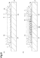
- the sample support body 1 is fixed to the glass slide 6, in a state in which the second surface 2b of the substrate 2 is brought into contact with the mixed liquid 80.
- the sample support body 1 is fixed to the glass slide 6 by a tape 7 having conductivity (for example, a carbon tape or the like).
- the tape 7 is in contact with the conductive layer 4 on the first surface 2a of the substrate 2, and is in contact with the mounting surface 6a of the glass slide 6, and thus, the sample support body 1 is fixed to the glass slide 6.
- the tape 7 may be a part of the sample support body 1, or may be prepared separately from the sample support body 1.
- the tape 7 may be fixed in advance to the first surface 2a side in a peripheral portion of the substrate 2. More specifically, the tape 7 may be fixed onto the conductive layer 4 in the peripheral portion of the substrate 2. As illustrated in (b) of FIG. 5 , the mixed liquid 80 is moved towards the first surface 2a side from the second surface 2b side of the sample support body 1 through each of the through holes 2c. Then, the mixed liquid 80 is remained on the first surface 2a side of the sample support body 1 in each of the through holes 2c by a surface tension.
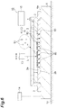
- the glass slide 6, the sample support body 1, and the mixed liquid 80 are mounted on a support portion 12 (for example, a stage) of a mass spectrometry device 10, in a state where the sample support body 1 and the mixed liquid 80 are mounted on the mounting surface 6a of the glass slide 6.
- an environment in which the glass slide 6, the sample support body 1, and the mixed liquid 80 are mounted is a vacuum state.
- a voltage is applied to the conductive layer 4 of the sample support body 1 via the mounting surface 6a of the glass slide 6 and the tape 7 by a voltage application unit 14 of the mass spectrometry device 10 (a third step).
- the first surface 2a of the substrate 2 is irradiated with laser beam L through the opening 3a of the frame 3 by a laser beam irradiation unit 13 of the mass spectrometry device 10 (the third step).
- the laser beam L is applied to a region corresponding to the opening 3a of the frame 3 on the first surface 2a of the substrate 2 (that is, a region corresponding to the effective region R).
- the laser beam irradiation unit 13 is capable of irradiating regions that correspond to the effective region R and are different from each other, with the laser beam L. Note that, the irradiation of the laser beam L with respect to the regions different from each other can be performed by operating at least one of the support portion 12 and the laser beam irradiation unit 13.
- the first surface 2a of the substrate 2 is irradiated with the laser beam L while a voltage is applied to the conductive layer 4. Accordingly, a component of the sample S in the mixed liquid 80 that is moved to the first surface 2a side of the substrate 2 is ionized, and a sample ion S1 (the component that is ionized) is emitted.
- the conductive layer 4, and the solvent 81 that is moved to the first surface 2a side of the substrate 2, along with the sample S absorb the energy of the laser beam L.
- the solvent 81 is gasified along with the component of the sample S by the energy.
- the first step to the third step described above correspond to the laser desorption/ionization method using the sample support body 1.
- the sample ion S1 that is emitted is moved towards a ground electrode (not illustrated) that is provided between the sample support body 1 and an ion detection unit 15 while being accelerated. That is, the sample ion S1 is moved towards the ground electrode while being accelerated by a potential difference that occurs between the conductive layer 4 to which the voltage is applied and the ground electrode. Then, the sample ion S1 is detected by the ion detection unit 15 of the mass spectrometry device 10 (a fourth step).
- the ion detection unit 15 detects the sample ion S1 to correspond to an irradiation position of the laser beam L.
- the mass spectrometry device 10 is a mass spectrometry device using a time-of-flight mass spectrometry (TOF-MS) method.
- TOF-MS time-of-flight mass spectrometry
- the sample S and the solvent 81 are introduced into the plurality of through holes 2c.
- the component of the sample S is remained on the first surface 2a side in each of the through holes 2c, along with the solvent 81.
- the first surface 2a is irradiated with the laser beam L while the voltage is applied to the conductive layer 4
- the energy is transmitted to the component of the sample S on the first surface 2a side. Accordingly, the component of the sample S is ionized.
- the solvent 81 has refractoriness in a vacuum.
- the solvent 81 is more reliably remained on the first surface 2a side, compared to a case where the solvent has volatility in a vacuum. Therefore, the component of the sample S is also more reliably remained on the first surface 2a side. That is, the solvent 81 and the sample S are remained on the first surface 2a side for a longer period of time. Accordingly, when the first surface 2a is irradiated with the laser beam L while the voltage is applied to the conductive layer 4, the component of the sample S is more reliably ionized.
- the solvent 81 and the component of the sample S are remained on the first surface 2a side for a longer period of time, and thus, the component of the sample S can be ionized by applying the laser beam L while applying the voltage for a longer period of time. Accordingly, it is possible to ionize the components of more samples S.
- the laser desorption/ionization method in the mass spectrometry, it is possible to improve a detection intensity of the ionized sample S. That is, when the mass spectrometry is performed with respect to the same samples, it is possible to improve the sensitivity of the mass spectrometry, compared to a case where the sample is not reliably ionized.
- the mixed liquid 80 is dropped onto the mounting surface 6a of the glass slide 6, and the sample support body 1 is disposed on the mixed liquid 80 such that the second surface 2b is in contact with the mixed liquid 80.
- the mixed liquid 80 is moved to the first surface 2a side from the second surface 2b side through each of the through holes 2c, and is remained on the first surface 2a side in each of the through holes 2c.
- the component of the sample S is more reliably remained on the first surface 2a side, and is more reliably ionized. Accordingly, in the mass spectrometry, it is possible to improve the detection intensity of the ionized sample S.
- the mass spectrometry method of the first embodiment it is possible to improve the detection intensity of the ionized sample S.
- FIG. 7 is a diagram illustrating results of a mass spectrometry method of a comparative example and an example.
- (a) of FIG. 7 is a diagram illustrating a result thereof.
- the detection intensity of the ionized sample S began to attenuate when one portion of the effective region R was irradiated with the laser beam L for 20 pulses. It is considered that this is because molecules mixed with the sample S were volatilized. For this reason, three portions of the effective region R were irradiated with the laser beam L for each 20 pulses, and an integrated value of detection results was obtained.
- FIG. 7 is a diagram illustrating a result thereof.
- one portion of the effective region R was irradiated with the laser beam L for 500 pulses, in the same condition as that of the comparative example.
- the detection intensity of the ionized sample was not attenuated when the laser beam L was applied for at least 20 pulses. This is because the sample S is remained on the first surface 2a side for a long period of time, along with the solvent 81.
- the detection intensity of the example was approximately 60 times the detection intensity of the comparative example. Accordingly, it was proved that in the mass spectrometry, it was possible to improve the detection intensity of the ionized sample S by using the sample support body 1 and the solvent 81.
- the laser desorption/ionization method and the mass spectrometry method of the second embodiment are mainly different from the laser desorption/ionization method and the mass spectrometry method of the first embodiment in that in the second step of introducing the sample and the solvent into the plurality of through holes 2c, the sample support body 1 is mounted on the mounting surface 6a of the glass slide 6, and then, the mixed liquid 80 is dropped onto the sample support body 1.
- the others are the same as the laser desorption/ionization method and the mass spectrometry method of the first embodiment, and thus, the detailed description will be omitted.
- the through hole 2c, the conductive layer 4, and the adhesive layer 5 in the sample support body 1 are not illustrated.
- a dimensional ratio or the like is different between the sample support body 1 illustrated in FIG. 1 and FIG 2 and the sample support body 1 illustrated in FIG. 8 and FIG. 9 .
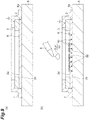
- the sample support body 1 described above is prepared (a first step). Subsequently, the sample and the solvent are introduced into the plurality of through holes 2c (a second step). Specifically, as illustrated in (b) of FIG 8 , the sample support body 1 is mounted on the mounting surface 6a such that the second surface 2b faces the mounting surface 6a. Subsequently, as illustrated in (a) of FIG. 9 , as with the first embodiment, the sample support body 1 is fixed to the glass slide 6 by the tape 7. Subsequently, as illustrated in (b) of FIG 9 , the mixed liquid 80, for example, is dropped into the plurality of through holes 2c from the first surface 2a by the pipette 8.
- the mixed liquid 80 is moved towards the second surface 2b side from the first surface 2a side of the sample support body 1 through each of the through holes 2c. Each of the through holes 2c is filled with the mixed liquid 80. The mixed liquid 80 is remained on the first surface 2a side of the sample support body 1 in each of the through holes 2c by the surface tension.
- the first surface 2a of the substrate 2 is irradiated with the laser beam L while the voltage is applied to the conductive layer 4. Accordingly, the component of the sample S in the mixed liquid 80 that is remained on the first surface 2a side of the substrate 2 is ionized, and the sample ion S1 (the ionized component) is emitted (a third step). Then, as with the first embodiment, the sample ion S1 is detected by the ion detection unit 15 of the mass spectrometry device 10 (a fourth step).
- the laser desorption/ionization method of the second embodiment includes each of the steps from the first step to the third step described above.
- the mass spectrometry method of the second embodiment includes each of the steps from the first step to the fourth step described above.
- the sample support body 1 is mounted on the mounting surface 6a such that the second surface 2b faces the mounting surface 6a of the glass slide 6, and the mixed liquid 80 is dropped into the plurality of through holes 2c from the first surface 2a side. Even in such a case, the mixed liquid 80 is remained on the first surface 2a side in each of the through holes 2c. Then, as with the first embodiment, the component of the sample S is more reliably remained on the first surface 2a side, and is more reliably ionized. Accordingly, in the mass spectrometry, it is possible to improve the detection intensity of the ionized sample S.
- the laser desorption/ionization method and the mass spectrometry method of the third embodiment are mainly different from the laser desorption/ionization method and the mass spectrometry method of the first embodiment in that in the second step, the sample and the solvent are not introduced into the through hole 2c of the sample support body 1 as a mixed liquid.
- the others are the same as the laser desorption/ionization method and the mass spectrometry method of the first embodiment, and thus, the detailed description will be omitted.
- the through hole 2c, the conductive layer 4, and the adhesive layer 5 in the sample support body 1 are not illustrated.
- a dimensional ratio or the like is different between the sample support body 1 illustrated in FIG. 1 and FIG. 2 and the sample support body 1 illustrated in FIG. 10 to FIG. 12 .
- the sample support body 1 described above is prepared (a first step). Subsequently, the sample and the solvent are introduced into the plurality of through holes 2c (a second step). Specifically, as illustrated in (a) of FIG. 10 , the sample S is mounted on the mounting surface 6a of the glass slide 6. Subsequently, as illustrated in (b) of FIG. 10 , the sample support body 1 is disposed on the sample S such that the second surface 2b is in contact with the sample S. At this time, the sample S is disposed in the effective region R when seen from the thickness direction of the substrate 2.
- the sample S for example, is a human hair.
- the sample S is a dry sample.
- a solution for example, an acetonitrile mixed liquid or the like
- a solution for example, an acetonitrile mixed liquid or the like
- the sample support body 1 is fixed to the glass slide 6 by the tape 7.
- the solvent 81 is introduced into the plurality of through holes 2c of the sample support body 1.
- the solvent 81 for example, is dropped into the plurality of through holes 2c from the first surface 2a side of the sample support body 1 by the pipette 8.
- the solvent 81 is dropped onto approximately the entire region of the effective region R to reach the entire region of the sample S.
- the solvent 81 for example, is applied into the plurality of through holes 2c from the first surface 2a side of the sample support body 1 with approximately a uniform amount by an airbrush or the like.
- the solvent 81 is moved towards the second surface 2b side from the first surface 2a side of the sample support body 1 through each of the through holes 2c.
- the solvent 81 is mixed with the component of the sample S that is in contact with the second surface 2b of the sample support body 1 in each of the through holes 2c.
- the component of the sample S is mixed with the solvent 81 that is moved to the second surface 2b side of the sample support body 1 and is moved towards the first surface 2a side from the second surface 2b side of the sample support body 1 through each of the through holes 2c, in each of the through holes 2c.
- the mixed liquid 80 of the component of the sample S and the solvent 81 is remained on the first surface 2a side of the sample support body 1 in each of the through holes 2c by the surface tension.
- the first surface 2a of the substrate 2 is irradiated with the laser beam L while the voltage is applied to the conductive layer 4, in a state where the sample S is disposed between the glass slide 6 and the sample support body 1. Accordingly, the component of the sample S that is mixed with the solvent 81 and is moved to the first surface 2a side from the second surface 2b side through the through hole 2c is ionized, and the sample ion S1 (the ionized component) is emitted (a third step).
- the laser beam irradiation unit 13 scans the region corresponding to the effective region R with the laser beam L. Note that, the scanning of the laser beam L with respect to the region corresponding to the effective region R can be performed by operating at least one of the support portion 12 and the laser beam irradiation unit 13.
- the sample ion S1 is detected by the ion detection unit 15 of the mass spectrometry device 10 (a fourth step).
- the ion detection unit 15 detects the sample ion S1 to corresponding to a scanning position of the laser beam L. Accordingly, it is possible to image a two-dimensional distribution of the molecules configuring the sample S.
- the laser desorption/ionization method of the third embodiment includes each of the steps from the first step to the third step described above.
- the mass spectrometry method of the third embodiment includes each of the steps from the first step to the fourth step described above.
- the sample S is mounted on the mounting surface 6a of the glass slide 6, the sample support body 1 is disposed on the sample S such that the second surface 2b is in contact with the sample S, and then, the solvent 81 is introduced into the plurality of through holes 2c, and in the third step, the component of the sample S that is mixed with the solvent 81 and is moved to the first surface 2a side from the second surface 2b side through the through hole 2c is ionized.
- the solvent 81 is moved to the second surface 2b side from the first surface 2a side through each of the through holes 2c, and is mixed with the component of the sample S.
- the component of the sample S is mixed with the solvent 81 and is moved to the first surface 2a side from the second surface 2b side through each of the through holes 2c.
- the component of the sample S is remained on the first surface 2a side, along with the solvent 81.
- the component of the sample S is extracted to the first surface 2a side from the second surface 2b side through the plurality of through holes 2c by the solvent 81.
- the solvent 81 has refractoriness in a vacuum. For this reason, the solvent 81 is more reliably remained on the first surface 2a side, compared to a case where the solvent has volatility in a vacuum.
- the component of the sample S that is extracted by the solvent 81 is also more reliably remained on the first surface 2a side. That is, the solvent 81 is remained on the first surface 2a side and in each of the through holes 2c for a longer period of time, and the sample S is extracted to the first surface 2a side by the solvent 81 for a longer period of time. Accordingly, when the first surface 2a is irradiated with the laser beam L while the voltage is applied to the conductive layer 4, the component of the sample S is more reliably ionized.
- the solvent 81 and the component of the sample S are remained on the first surface 2a side for a longer period of time, and thus, it is possible to ionize the component of the sample S by applying the laser beam L while applying the voltage for a longer period of time. Accordingly, it is possible to ionize the components of more samples S.
- the laser desorption/ionization method in the mass spectrometry, it is possible to improve the detection intensity of the ionized sample S.
- the solvent 81 is dropped into the plurality of through holes 2c from the first surface 2a side. In this case, it is possible to easily introduce the solvent 81 into each of the through holes 2c.
- the sample S is the dry sample.
- the component of the sample S is mixed with the solvent 81 and is moved, and thus, even in a case where the sample S is the dry sample, it is possible to smoothly move the component of the sample S.
- the laser desorption/ionization method and the mass spectrometry method of the fourth embodiment are mainly different from the laser desorption/ionization method and the mass spectrometry method of the third embodiment in that in the second step, the solvent 81 is introduced into the through hole 2c of the sample support body 1, and then, the sample support body 1 into which the solvent 81 is introduced is disposed on the sample S.
- the others are the same as the laser desorption/ionization method and the mass spectrometry method of the third embodiment, and thus, the detailed description will be omitted.
- the through hole 2c, the conductive layer 4, and the adhesive layer 5 in the sample support body 1 are not illustrated.
- a dimensional ratio or the like is different between the sample support body 1 illustrated in FIG. 1 and FIG. 2 and the sample support body 1 illustrated in FIG. 13 and FIG. 14 .
- the sample support body 1 described above is prepared (a first step).
- the sample and the solvent are introduced into the plurality of through holes 2c (a second step).
- the solvent 81 is introduced into the plurality of through holes 2c of the sample support body 1.
- the solvent 81 for example, is dropped into the plurality of through holes 2c from the first surface 2a side of the sample support body 1 by the pipette 8.
- the solvent 81 is dropped onto approximately the entire region of the effective region R. More preferably, the solvent 81, for example, is applied into the plurality of through holes 2c from the first surface 2a side of the sample support body 1 with approximately a uniform amount by an airbrush or the like.
- the solvent 81 is moved towards the second surface 2b side from the first surface 2a side of the sample support body 1 through each of the through holes 2c.
- Each of the through holes 2c is filled with the solvent 81.
- the sample S is mounted on the mounting surface 6a of the glass slide 6.
- the sample support body 1 is disposed on the sample S such that the second surface 2b is in contact with the sample S.
- the sample support body 1 is fixed to the glass slide 6 by the tape 7.
- the solvent 81 in each of the through holes 2c is mixed with the component of the sample S that is in contact with the second surface 2b of the sample support body 1, in each of the through holes 2c.
- the component of the sample S is mixed with the solvent 81 and is moved towards the first surface 2a side from the second surface 2b side of the sample support body 1 through each of the through holes 2c.
- the mixed liquid 80 of the component of the sample S and the solvent 81 is remained on the first surface 2a side of the sample support body 1 in each of the through holes 2c by the surface tension.
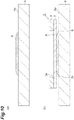
- the first surface 2a of the sample support body 1 is irradiated with the laser beam L by the laser beam irradiation unit 13 while the voltage is applied to the conductive layer 4 by the voltage application unit 14, in a state where the sample S is disposed between the glass slide 6 and the sample support body 1. Accordingly, the component of the sample S that is moved to the first surface 2a side of the substrate 2 is ionized, and the sample ion S1 (the ionized component) is emitted (a third step). Then, as with the third embodiment, the sample ion S1 is detected by the ion detection unit 15 of the mass spectrometry device 10 (a fourth step).
- the laser desorption/ionization method of the fourth embodiment includes each of the steps from the first step to the third step described above.
- the mass spectrometry method of the fourth embodiment includes each of the steps from the first step to the fourth step described above.
- the solvent 81 is introduced into the plurality of through holes 2c, the sample S is mounted on the mounting surface 6a of the glass slide 6, and then, the sample support body 1 is disposed on the sample S such that the second surface 2b is in contact with the sample S, and in the third step, the component of the sample S that is mixed with the solvent 81 and is moved to the first surface 2a side from the second surface 2b side through the through hole 2c is ionized.
- the component of the sample S is mixed with the solvent 81 and is moved to the first surface 2a side from the second surface 2b side through each of the through holes 2c.
- the component of the sample S is remained on the first surface 2a side, along with the solvent 81. As described above, the component of the sample S is extracted to the first surface 2a side from the second surface 2b side through the plurality of through holes 2c by the solvent 81. Then, as with the third embodiment, the component of the sample S is more reliably remained on the first surface 2a side, and is more reliably ionized. Accordingly, in the mass spectrometry, it is possible to improve the detection intensity of the ionized sample S.
- the solvent 81 is dropped into the plurality of through holes 2c from the first surface 2a side. In this case, it is possible to easily introduce the solvent 81 into each of the through holes 2c.
- the conductive layer 4 may not be provided on the second surface 2b of the substrate 2 and the inner surface of the through hole 2c, insofar as the conductive layer 4 is provided on at least the first surface 2a of the substrate 2.
- the conductive layer 4 may be provided on the second surface 2b of the substrate 2 and the inner surface of the through hole 2c.
- the sample support body 1 may be fixed to the glass slide 6 by means other than the tape 7 (for example, means using an adhesive agent, a fixing tool, or the like).
- the voltage may be applied to the conductive layer 4 without using the mounting surface 6a of the glass slide 6 and the tape 7.
- the glass slide 6 and the tape 7 may not have conductivity.
- the substrate 2 may have conductivity, and in the third step, the voltage may be applied to the substrate 2. In this case, it is possible to omit the conductive layer 4 from the sample support body 1, and to obtain the same effect as that of a case where the sample support body 1 including the conductive layer 4 as described above is used.
- sample S is a peptide sample or a human hair
- sample S may be various.
- sample S is the dry sample, but the sample S may be a hydrous sample.
- the solvent 81 may be a solvent having refractoriness in a vacuum.
- the solvent 81 may be at least one selected from glycerin, diethanol amine, triethanol amine, nitrobenzyl alcohol, nitrophenyl octyl ether, thioglycerol, diethylene glycol, triethylene glycol, tetraethylene glycol, liquid paraffin, sulfolane, dithiothreitol, a mixture of dithiothreitol and thioglycerol, a mixture of dithiothreitol and nitrobenzyl alcohol, and a mixture of dithiothreitol and dithioerythritol.
- the solvent 81 may be at least one selected from glycerin, diethanol amine, triethanol amine, nitrobenzyl alcohol, nitrophenyl octyl ether, thioglycerol, diethylene glycol, triethylene glycol, tetraethylene
- the region corresponding to the effective region R may be irradiated with the laser beam L by the laser beam irradiation unit 13 at one time, and the sample ion S1 may be detected by the ion detection unit 15 while two-dimensional information of the region is maintained. That is, the mass spectrometry device 10 may be a projection mass spectrometry device.
- the laser desorption/ionization method of each of the embodiments described above can be used not only in imaging mass spectrometry in which the mass spectrum of the sample S is measured or the two-dimensional distribution of the molecules configuring the sample S is imaged, but also in other measurements and tests such as ion mobility measurement.
- the solvent 81 is dropped into the plurality of through holes 2c from first surface 2a side, but the solvent 81 may be dropped into the plurality of through holes 2c from the second surface 2b side.
- the sample support body 1 may be dipped in the solvent 81.
- the solvent 81 may be introduced into the plurality of through holes 2c, in a state of being heated and evaporated.
- the solvent 81 that is introduced into the plurality of through holes 2c in the evaporated state is cooled at a normal temperature, and thus, fills each of the through holes 2c, and is in contact with the sample support body 1, and therefore, is remained in each of the through holes 2c. In any case, it is possible to easily introduce the solvent 81 into each of the through holes 2c.
- the opening 3a of the frame 3 is in the shape of a circle when seen from the thickness direction of the substrate 2, but the opening 3a may have various shapes.
- the opening 3a of the frame 3, for example, may be in the shape of a rectangle.
- the sample S is mounted on the glass slide 6, but the sample S may be directly mounted on the support portion 12 of the mass spectrometry device 10.
- the support portion 12 of the mass spectrometry device 10 corresponds to the glass slide 6.
- the application of the sample support body 1 is not limited to the ionization of the sample S by the irradiation of the laser beam L.
- the sample support body 1 may be used in the ionization of the sample S by the irradiation of energy beam (for example, an ion beam, an electron beam, and the like) other than the laser beam L.
- 1 sample support body
- 2 substrate
- 2a first surface
- 2b second surface
- 2c through hole
- 4 conductive layer
- 6 glass slide (mounting portion)
- 6a mounting surface
- 80 mixed liquid
- 81 solvent
- L laser beam
- S sample.
Landscapes
- Chemical & Material Sciences (AREA)
- Analytical Chemistry (AREA)
- Physics & Mathematics (AREA)
- Optics & Photonics (AREA)
- Engineering & Computer Science (AREA)
- Plasma & Fusion (AREA)
- Other Investigation Or Analysis Of Materials By Electrical Means (AREA)
Abstract
Description
- The present disclosure relates to a laser desorption/ionization method and a mass spectrometry method.
- In the related art, a matrix-assisted laser desorption/ionization method (MALDI) is known as a method of ionizing a sample such as a biological sample in order to perform mass spectrometry or the like (for example, refer to Patent Literature 1). The MALDI is a method of ionizing a sample by adding a low-molecular-weight organic compound referred to as a matrix that absorbs laser beam into the sample, and by irradiating the sample with laser beam. According to such a method, it is possible to ionize a thermally unstable substance or a high-molecular-weight substance in a non-destructive manner (so-called soft ionization).
- On the other hand, a surface-assisted laser desorption/ionization method (SALDI) is known as a method of performing ionization without using the matrix (for example, refer to
Patent Literatures 2 and 3). The SALDI is a method of ionizing a sample by dropping the sample onto an ionization substrate having a fine concavo-convex structure on a surface, and by irradiating the sample with laser beam. -
- Patent Literature 1:
US Patent No. 7695978 - Patent Literature 2: Japanese Patent No.
5129628 - Patent Literature 3:
US Patent No. 6288390 - In the mass spectrometry, the ionized sample is detected, and the mass spectrometry of the sample is performed on the basis of a detection result thereof. Therefore, in the mass spectrometry, it is desirable to improve a detection intensity (a sensitivity) of the ionized sample.
- Therefore, an object of the present disclosure is to provide a laser desorption/ionization method and a mass spectrometry method in which in mass spectrometry, a detection intensity of an ionized sample can be improved.
- A laser desorption/ionization method of one aspect of the present disclosure, includes: a first step of preparing a sample support body including a substrate on which a plurality of through holes opening to a first surface and a second surface facing each other are formed, and a conductive layer provided on at least the first surface; a second step of introducing a sample and a solvent having refractoriness in a vacuum into the plurality of through holes; and a third step of ionizing a component of the sample by irradiating the first surface with laser beam while applying a voltage to the conductive layer.
- In the laser desorption/ionization method, the sample and the solvent are introduced into the plurality of through holes. The component of the sample is remained on the first surface side in each of the through holes, along with the solvent. Then, in a case where the first surface is irradiated with the laser beam while the voltage is applied to the conductive layer, energy is transmitted to the component of the sample on the first surface side. Accordingly, the component of the sample is ionized. In the laser desorption/ionization method, the solvent has refractoriness in a vacuum. For this reason, the solvent is more reliably remained on the first surface side, compared to a case where the solvent has volatility in a vacuum. Therefore, the component of the sample is also more reliably remained on the first surface side. Accordingly, when the first surface is irradiated with the laser beam while the voltage is applied to the conductive layer, the component of the sample is more reliably ionized. As described above, according to the laser desorption/ionization method, in mass spectrometry, it is possible to improve a detection intensity of the ionized sample.
- In the laser desorption/ionization method of one aspect of the present disclosure, in the second step, a mixed liquid of the sample and the solvent may be dropped onto a mounting surface of a mounting portion, and the sample support body may be disposed on the mixed liquid such that the second surface is in contact with the mixed liquid, and in the third step, the component of the sample in the mixed liquid that is moved to the first surface side from the second surface side through the through hole may be ionized by irradiating the first surface with the laser beam while applying the voltage to the conductive layer. In this case, the mixed liquid containing the sample is moved to the first surface side from the second surface side through each of the through holes. The mixed liquid is remained on the first surface side in each of the through holes. Then, as described above, the component of the sample is more reliably remained on the first surface side, and is more reliably ionized. Accordingly, in the mass spectrometry, it is possible to improve the detection intensity of the ionized sample.
- In the laser desorption/ionization method of one aspect of the present disclosure, in the second step, the sample support body may be mounted on the mounting surface such that the second surface faces the mounting surface of the mounting portion, and the mixed liquid of the sample and the solvent may be dropped into the plurality of through holes from the first surface side, and in the third step, the component of the sample in the mixed liquid that is remained on the first surface side may be ionized by irradiating the first surface with the laser beam while applying the voltage to the conductive layer. In this case, the mixed liquid containing the sample is moved to the second surface side from the first surface side through each of the through holes, and each of the through holes is filled with the mixed liquid. The mixed liquid is remained on the first surface side in each of the through holes. Then, as described above, the component of the sample is more reliably remained on the first surface side, and is more reliably ionized. Accordingly, in the mass spectrometry, it is possible to improve the detection intensity of the ionized sample.
- In the laser desorption/ionization method of one aspect of the present disclosure, in the second step, the sample may be mounted on the mounting surface of the mounting portion, the sample support body may be disposed on the sample such that the second surface is in contact with the sample, and then, the solvent may be introduced into the plurality of through holes, and in the third step, the component of the sample that is mixed with the solvent and is moved to the first surface side from the second surface side through the through hole may be ionized by irradiating the first surface with the laser beam while applying the voltage to the conductive layer, in a state in which the sample is disposed between the mounting portion and the sample support body. In this case, the solvent is moved to the second surface side from the first surface side through each of the through holes, and is mixed with the component of the sample. The component of the sample is mixed with the solvent and is moved to the first surface side from the second surface side through each of the through holes. The component of the sample is remained on the first surface side, along with the solvent. Then, as described above, the component of the sample is more reliably remained on the first surface side, and is more reliably ionized. Accordingly, in the mass spectrometry, it is possible to improve the detection intensity of the ionized sample.
- In the laser desorption/ionization method of one aspect of the present disclosure, in the second step, the solvent may be introduced into the plurality of through holes, the sample may be mounted on the mounting surface of the mounting portion, and then, the sample support body may be disposed on the sample such that the second surface is in contact with the sample, and in the third step, the component of the sample that mixed with the solvent and is moved to the first surface side from the second surface side through the through hole may be ionized by irradiating the first surface with the laser beam while applying the voltage to the conductive layer, in a state in which the sample is disposed between the mounting portion and the sample support body. In this case, the sample support body in which the solvent is introduced into the plurality of through holes is disposed on the sample. The component of the sample is mixed with the solvent and is moved to the first surface side from the second surface side through each of the through holes. The component of the sample is remained on the first surface side, along with the solvent. Then, as described above, the component of the sample is more reliably remained on the first surface side, and is more reliably ionized. Accordingly, in the mass spectrometry, it is possible to improve the detection intensity of the ionized sample.
- In the laser desorption/ionization method of one aspect of the present disclosure, in the second step, the solvent may be dropped into the plurality of through holes from the first surface side. In this case, it is possible to easily introduce the solvent into each of the through holes.
- In the laser desorption/ionization method of one aspect of the present disclosure, in the second step, the solvent may be dropped into the plurality of through holes from the first surface side or the second surface side. In this case, it is possible to easily introduce the solvent into each of the through holes.
- In the laser desorption/ionization method of one aspect of the present disclosure, in the second step, the sample support body may be dipped in the solvent. In this case, it is possible to easily introduce the solvent into each of the through holes.
- In the laser desorption/ionization method of one aspect of the present disclosure, in the second step, the solvent may be introduced into the plurality of through holes in a state of being heated and evaporate. In this case, it is possible to easily introduce the solvent into each of the through holes.
- In the laser desorption/ionization method of one aspect of the present disclosure, the sample may be a dry sample. In the laser desorption/ionization method, the component of the sample is mixed with the solvent and is moved, and thus, even in a case where the sample is the dry sample, it is possible to smoothly move the component of the sample.
- A laser desorption/ionization method of one aspect of the present disclosure, includes: a first step of preparing a sample support body including a substrate having conductivity on which a plurality of through holes opening to a first surface and a second surface facing each other are formed; a second step of introducing a sample and a solvent having refractoriness in a vacuum into the plurality of through holes; and a third step of ionizing a component of the sample by irradiating the first surface with laser beam while applying a voltage to the substrate.
- According to the laser desorption/ionization method, it is possible to omit the conductive layer from the sample support body, and to obtain the same effect as that of a case where the sample support body including the conductive layer as described above is used.
- In the laser desorption/ionization method of one aspect of the present disclosure, the solvent may be at least one selected from glycerin, diethanol amine, triethanol amine, nitrobenzyl alcohol, nitrophenyl octyl ether, thioglycerol, diethylene glycol, triethylene glycol, tetraethylene glycol, liquid paraffin, sulfolane, dithiothreitol, a mixture of dithiothreitol and thioglycerol, a mixture of dithiothreitol and nitrobenzyl alcohol, and a mixture of dithiothreitol and dithioerythritol. In this case, in the mass spectrometry, it is possible to improve the detection intensity of the ionized sample by using the solvent having refractoriness in a vacuum.
- A mass spectrometry method of one aspect of the present disclosure, includes: each of the steps of the laser desorption/ionization method described above; and a fourth step of detecting the component that is ionized in the third step.
- According to the mass spectrometry method, it is possible to improve the detection intensity of the ionized sample.
- According to the present disclosure, it is possible to provide a laser desorption/ionization method and a mass spectrometry method in which in mass spectrometry, a detection intensity of an ionized sample can be improved.
-
-
FIG. 1 is a plan view of a sample support body that is used in a laser desorption/ionization method and a mass spectrometry method of a first embodiment. -
FIG. 2 is a sectional view of the sample support body along line II-II illustrated inFIG. 1 . -
FIG. 3 is a diagram illustrating an enlarged image of a substrate of the sample support body illustrated inFIG. 1 . -
FIG. 4 is a diagram illustrating steps of the mass spectrometry method of the first embodiment. -
FIG. 5 is a diagram illustrating the steps of the mass spectrometry method of the first embodiment. -
FIG. 6 is a diagram illustrating the steps of the mass spectrometry method of the first embodiment. - (a) of
FIG. 7 is a mass spectrum of a mass spectrometry method of a comparative example and (b) ofFIG. 7 is a mass spectrum of a mass spectrometry method of an example. -
FIG. 8 is a diagram illustrating steps of a mass spectrometry method of a second embodiment. -
FIG. 9 is a diagram illustrating the steps of the mass spectrometry method of the second embodiment. -
FIG. 10 is a diagram illustrating steps of a mass spectrometry method of a third embodiment. -
FIG. 11 is a diagram illustrating the steps of the mass spectrometry method of the third embodiment. -
FIG. 12 is a diagram illustrating the steps of the mass spectrometry method of the third embodiment. -
FIG. 13 is a diagram illustrating steps of a mass spectrometry method of a fourth embodiment. -
FIG. 14 is a diagram illustrating steps of a mass spectrometry method of the fourth embodiment. - Hereinafter, embodiments of the present invention will be described in detail with reference to the drawings. Note that, in each of the drawings, the same reference numerals will be applied to the same portions or the corresponding portions, and the repeated description will be omitted.
- First, a sample support body that is used in a laser desorption/ionization method and a mass spectrometry method of a first embodiment to a fourth embodiment will be described. As illustrated in
FIG 1 andFIG. 2 , asample support body 1 includes asubstrate 2, aframe 3, and aconductive layer 4. Thesubstrate 2 includes afirst surface 2a and asecond surface 2b facing each other. A plurality of throughholes 2c are formed on thesubstrate 2 uniformly (with a homogeneous distribution). Each of the throughholes 2c extends along a thickness direction of the substrate 2 (a direction perpendicular to thefirst surface 2a and thesecond surface 2b), and opens to thefirst surface 2a and thesecond surface 2b. - The
substrate 2, for example, is formed of an insulating material into the shape of a rectangular plate. The length of one side of thesubstrate 2 when seen from the thickness direction of thesubstrate 2, for example, is approximately several cm, and the thickness of thesubstrate 2, for example, is approximately 1 µm to 50 µm. The throughhole 2c, for example, is approximately in the shape of a circle when seen from the thickness direction of thesubstrate 2. The width of the throughhole 2c is 1 nm to 700 nm. The width of the throughhole 2c indicates the diameter of the throughhole 2c in a case where the throughhole 2c is approximately in the shape of a circle when seen from the thickness direction of thesubstrate 2, and indicates the diameter (an effective diameter) of a virtual maximum cylinder falling into the throughhole 2c in a case where the throughhole 2c is not approximately in the shape of a circle. A pitch between the respective throughholes 2c is 1 nm to 1000 nm. In a case where the throughhole 2c is approximately in the shape of a circle when seen from the thickness direction of thesubstrate 2, the pitch between the respective throughholes 2c indicates a center-to-center distance of the respective circles, and in a case where the throughhole 2c is not approximately in the shape of a circle, the pitch between the respective throughholes 2c indicates a center axis-to-center axis distance of the virtual maximum cylinder falling into the throughhole 2c. - The
frame 3 is provided on thefirst surface 2a of thesubstrate 2. Specifically, theframe 3 is fixed to thefirst surface 2a of thesubstrate 2 by an adhesive layer 5. It is preferable that an adhesive material having less emitted gas (for example, glass with a low melting point, a vacuum adhesive agent, and the like) is used as the material of the adhesive layer 5. Theframe 3 has approximately the same outer shape as that of thesubstrate 2 when seen from the thickness direction of thesubstrate 2. Anopening 3a is formed in theframe 3. A portion corresponding to theopening 3a in thesubstrate 2 functions as an effective region R for moving a component of a sample described below to thefirst surface 2a side. - The
frame 3, for example, is formed into the shape of a rectangular plate by the insulating material. The length of one side of theframe 3 when seen from the thickness direction of thesubstrate 2, for example, is approximately several cm, and the thickness of theframe 3, for example, is less than or equal to 1 mm. Theopening 3a, for example, is in the shape of a circle when seen from the thickness direction of thesubstrate 2, and in such a case, the diameter of theopening 3a, for example, is approximately several mm to several tens of mm. By such aframe 3, the handling of thesample support body 1 is facilitated, and the deformation of thesubstrate 2 due to a temperature change or the like is suppressed. - The
conductive layer 4 is provided on thefirst surface 2a of thesubstrate 2. Specifically, theconductive layer 4 is formed in a region corresponding to theopening 3a of theframe 3 on thefirst surface 2a of the substrate 2 (that is, a region corresponding to the effective region R), and is continuously (integrally) formed on an inner surface of theopening 3a, and asurface 3b of theframe 3 on a side opposite to thesubstrate 2. In the effective region R, theconductive layer 4 covers a portion in which the throughhole 2c is not formed on thefirst surface 2a of thesubstrate 2. That is, in the effective region R, each of the throughholes 2c is exposed to theopening 3a. - The
conductive layer 4 is formed of a conductive material. However, it is preferable that a metal having low affinity (reactivity) with respect to a sample S and high conductivity is used as the material of theconductive layer 4, from the following reasons. - For example, in a case where the
conductive layer 4 is formed of a metal such as copper (Cu) having high affinity with respect to a sample such as protein, in a process of ionizing the sample described below, the sample is ionized in a state where Cu atoms are attached to sample molecules. As a result thereof, there is a concern that a detection result is shifted in the mass spectrometry method described below as the Cu atoms are attached. Therefore, it is preferable that a metal having low affinity with respect to the sample is used as the material of theconductive layer 4. - On the other hand, a metal having high conductivity easily and stably applies a constant voltage. For this reason, in a case where the
conductive layer 4 is formed of the metal having high conductivity, it is possible to homogeneously apply a voltage to thefirst surface 2a of thesubstrate 2 in the effective region R. In addition, there is a tendency that the metal having high conductivity also has high thermal conductivity. For this reason, in a case where theconductive layer 4 is formed of the metal having high conductivity, it is possible to efficiently transfer the energy of laser beam that is applied to thesubstrate 2 to the sample via theconductive layer 4. Therefore, it is preferable that the metal having high conductivity is used as the material of theconductive layer 4. - From the viewpoint described above, for example, it is preferable that gold (Au), platinum (Pt), and the like are used as the material of the
conductive layer 4. Theconductive layer 4, for example, is formed to have a thickness of approximately 1 nm to 350 nm by a plating method, an atomic layer deposition (ALD) method, a vapor deposition method, a sputtering method, and the like. Note that, for example, chromium (Cr), nickel (Ni), titanium (Ti), and the like may be used as the material of theconductive layer 4. -
FIG. 3 is a diagram illustrating an enlarged image of thesubstrate 2 when seen from the thickness direction of thesubstrate 2. InFIG. 3 , a black portion is the throughhole 2c, and a white portion is a partition portion between the throughholes 2c. As illustrated inFIG. 3 , the plurality of throughholes 2c having an approximately constant width are uniformly formed on thesubstrate 2. It is preferable that an opening rate of the throughholes 2c in the effective region R (a ratio of all of the throughholes 2c to the effective region R when seen from the thickness direction of the substrate 2) is practically 10% to 80%, and is particularly 60% to 80%. The sizes of the plurality of throughholes 2c may be uneven with each other, and the plurality of throughholes 2c may be partially connected to each other. - The
substrate 2 illustrated inFIG. 3 is an alumina porous film that is formed by performing anodic oxidation with respect to aluminum (Al). Specifically, an anodic oxidation treatment is performed with respect to an Al substrate, and a surface portion that is oxidized is peeled off from the Al substrate, and thus, it is possible to obtain thesubstrate 2. Note that, thesubstrate 2 may be formed by performing anodic oxidation with respect to a valve metal other than Al, such as tantalum (Ta), niobium (Nb), titanium (Ti), hafnium (Hf), zirconium (Zr), zinc (Zn), tungsten (W), bismuth (Bi), and antimony (Sb), or may be formed by performing anodic oxidation with respect to silicon (Si). - Next, the laser desorption/ionization method and the mass spectrometry method of the first embodiment will be described. In
FIG. 4 to FIG. 6 , the throughhole 2c, theconductive layer 4, and the adhesive layer 5 in thesample support body 1 are not illustrated. In addition, for the convenience of illustration, a dimensional ratio or the like is different between thesample support body 1 illustrated inFIG. 1 andFIG. 2 and thesample support body 1 illustrated inFIG. 4 to FIG. 6 . - First, the
sample support body 1 described above is prepared (a first step). Thesample support body 1 may be prepared by being manufactured by a person who carries out the laser desorption/ionization method and the mass spectrometry method, or may be prepared by being acquired from a manufacturer, a seller, or the like of thesample support body 1. - Subsequently, the sample that is a mass spectrometry target and a solvent are introduced into the plurality of through
holes 2c (a second step). Specifically, as illustrated in (a) ofFIG. 4 , amixed liquid 80 of the sample S and a solvent 81, for example, is dropped onto a mountingsurface 6a of a glass slide (a mounting portion) 6 by apipette 8. Theglass slide 6 is a glass substrate on which a transparent conductive film such as an indium tin oxide (ITO) film is formed, and the surface of the transparent conductive film is the mountingsurface 6a. Note that, not only theglass slide 6 but also a member that is capable of ensuring conductivity (for example, a substrate formed of a metal material such as stainless steel, or the like) can be used as the mounting portion. Subsequently, as illustrated in (b) ofFIG. 4 , thesample support body 1 is disposed on themixed liquid 80 such that thesecond surface 2b is in contact with themixed liquid 80. At this time, themixed liquid 80 is disposed in the effective region R when seen from the thickness direction of thesubstrate 2. - Here, the
mixed liquid 80 is a solution containing the sample S and the solvent 81. The sample S, for example, is a peptide sample. The solvent 81, for example, is an organic solvent. The solvent 81 has refractoriness in a vacuum. "Having refractoriness in a vacuum" indicates having refractoriness higher than that of water in a vacuum. That is, "having refractoriness in a vacuum" indicates having less volatility than that of water in a vacuum. "Having refractoriness in a vacuum" indicates that volatility in a vacuum is lower than volatility of water in vacuum. - In the atmosphere, the volatility of the solvent 81 is lower than the volatility of water. In a vacuum, the volatility of the solvent 81 is lower than the volatility of water. In the atmosphere, the volatility of the solvent 81 is lower than the volatility of acetone. In a vacuum, the volatility of the solvent 81 is lower than the volatility of acetone. In the atmosphere, the volatility of the solvent 81 is lower than the volatility of acetonitrile. In a vacuum, the volatility of the solvent 81 is lower than the volatility of acetonitrile. In the atmosphere, the solvent 81 is in a liquid form, and has fluidity. In a vacuum, the solvent 81 is in a liquid form, and has fluidity. In the atmosphere, a surface tension of the solvent 81 is lower than a surface tension of water. In a vacuum, the surface tension of the solvent 81 is lower than the surface tension of water. The solvent 81, for example, is glycerin (glycerol).
- Subsequently, as illustrated in (a) of
FIG. 5 , thesample support body 1 is fixed to theglass slide 6, in a state in which thesecond surface 2b of thesubstrate 2 is brought into contact with themixed liquid 80. At this time, thesample support body 1 is fixed to theglass slide 6 by atape 7 having conductivity (for example, a carbon tape or the like). Specifically, thetape 7 is in contact with theconductive layer 4 on thefirst surface 2a of thesubstrate 2, and is in contact with the mountingsurface 6a of theglass slide 6, and thus, thesample support body 1 is fixed to theglass slide 6. Thetape 7 may be a part of thesample support body 1, or may be prepared separately from thesample support body 1. In a case where thetape 7 is a part of the sample support body 1 (that is, in a case where thesample support body 1 includes the tape 7), for example, thetape 7 may be fixed in advance to thefirst surface 2a side in a peripheral portion of thesubstrate 2. More specifically, thetape 7 may be fixed onto theconductive layer 4 in the peripheral portion of thesubstrate 2. As illustrated in (b) ofFIG. 5 , themixed liquid 80 is moved towards thefirst surface 2a side from thesecond surface 2b side of thesample support body 1 through each of the throughholes 2c. Then, themixed liquid 80 is remained on thefirst surface 2a side of thesample support body 1 in each of the throughholes 2c by a surface tension. - Subsequently, as illustrated in
FIG. 6 , theglass slide 6, thesample support body 1, and themixed liquid 80 are mounted on a support portion 12 (for example, a stage) of amass spectrometry device 10, in a state where thesample support body 1 and themixed liquid 80 are mounted on the mountingsurface 6a of theglass slide 6. Subsequently, an environment in which theglass slide 6, thesample support body 1, and themixed liquid 80 are mounted is a vacuum state. Subsequently, a voltage is applied to theconductive layer 4 of thesample support body 1 via the mountingsurface 6a of theglass slide 6 and thetape 7 by avoltage application unit 14 of the mass spectrometry device 10 (a third step). Subsequently, thefirst surface 2a of thesubstrate 2 is irradiated with laser beam L through theopening 3a of theframe 3 by a laserbeam irradiation unit 13 of the mass spectrometry device 10 (the third step). - That is, the laser beam L is applied to a region corresponding to the
opening 3a of theframe 3 on thefirst surface 2a of the substrate 2 (that is, a region corresponding to the effective region R). Here, the laserbeam irradiation unit 13 is capable of irradiating regions that correspond to the effective region R and are different from each other, with the laser beam L. Note that, the irradiation of the laser beam L with respect to the regions different from each other can be performed by operating at least one of thesupport portion 12 and the laserbeam irradiation unit 13. - As described above, the
first surface 2a of thesubstrate 2 is irradiated with the laser beam L while a voltage is applied to theconductive layer 4. Accordingly, a component of the sample S in themixed liquid 80 that is moved to thefirst surface 2a side of thesubstrate 2 is ionized, and a sample ion S1 (the component that is ionized) is emitted. Specifically, theconductive layer 4, and the solvent 81 that is moved to thefirst surface 2a side of thesubstrate 2, along with the sample S, absorb the energy of the laser beam L. The solvent 81 is gasified along with the component of the sample S by the energy. Then, a proton or a cation is added to the molecules of the component of the sample S that is gasified, and thus, the sample ion S1 is obtained. The first step to the third step described above correspond to the laser desorption/ionization method using thesample support body 1. - The sample ion S1 that is emitted is moved towards a ground electrode (not illustrated) that is provided between the
sample support body 1 and anion detection unit 15 while being accelerated. That is, the sample ion S1 is moved towards the ground electrode while being accelerated by a potential difference that occurs between theconductive layer 4 to which the voltage is applied and the ground electrode. Then, the sample ion S1 is detected by theion detection unit 15 of the mass spectrometry device 10 (a fourth step). Here, theion detection unit 15 detects the sample ion S1 to correspond to an irradiation position of the laser beam L. Note that, here, themass spectrometry device 10 is a mass spectrometry device using a time-of-flight mass spectrometry (TOF-MS) method. The first step to the fourth step described above correspond to the mass spectrometry method using thesample support body 1. - As described above, in the laser desorption/ionization method of the first embodiment, the sample S and the solvent 81 are introduced into the plurality of through
holes 2c. The component of the sample S is remained on thefirst surface 2a side in each of the throughholes 2c, along with the solvent 81. Then, in a case where thefirst surface 2a is irradiated with the laser beam L while the voltage is applied to theconductive layer 4, the energy is transmitted to the component of the sample S on thefirst surface 2a side. Accordingly, the component of the sample S is ionized. In the laser desorption/ionization method, the solvent 81 has refractoriness in a vacuum. For this reason, the solvent 81 is more reliably remained on thefirst surface 2a side, compared to a case where the solvent has volatility in a vacuum. Therefore, the component of the sample S is also more reliably remained on thefirst surface 2a side. That is, the solvent 81 and the sample S are remained on thefirst surface 2a side for a longer period of time. Accordingly, when thefirst surface 2a is irradiated with the laser beam L while the voltage is applied to theconductive layer 4, the component of the sample S is more reliably ionized. That is, the solvent 81 and the component of the sample S are remained on thefirst surface 2a side for a longer period of time, and thus, the component of the sample S can be ionized by applying the laser beam L while applying the voltage for a longer period of time. Accordingly, it is possible to ionize the components of more samples S. As described above, according to the laser desorption/ionization method, in the mass spectrometry, it is possible to improve a detection intensity of the ionized sample S. That is, when the mass spectrometry is performed with respect to the same samples, it is possible to improve the sensitivity of the mass spectrometry, compared to a case where the sample is not reliably ionized. - In addition, in the laser desorption/ionization method of the first embodiment, in the second step, the
mixed liquid 80 is dropped onto the mountingsurface 6a of theglass slide 6, and thesample support body 1 is disposed on themixed liquid 80 such that thesecond surface 2b is in contact with themixed liquid 80. In this case, themixed liquid 80 is moved to thefirst surface 2a side from thesecond surface 2b side through each of the throughholes 2c, and is remained on thefirst surface 2a side in each of the throughholes 2c. Then, as described above, the component of the sample S is more reliably remained on thefirst surface 2a side, and is more reliably ionized. Accordingly, in the mass spectrometry, it is possible to improve the detection intensity of the ionized sample S. - According to the mass spectrometry method of the first embodiment, it is possible to improve the detection intensity of the ionized sample S.
-
FIG. 7 is a diagram illustrating results of a mass spectrometry method of a comparative example and an example. In the comparative example, a solution mixed as Angiotensin II (the sample S) : Diammonium Citrate (DHC) : Citric Acid (CHAc) : Acetonitrile (ACN) = 1 : 1 : 1 : 1 (Angiotensin II: 1 mM, DHC: 0.2 M, CHAc: 0.2 M, and ACN) was prepared, and a mass spectrum was measured by using thesample support body 1 and the solution. (a) ofFIG. 7 is a diagram illustrating a result thereof. In the comparative example, the detection intensity of the ionized sample S began to attenuate when one portion of the effective region R was irradiated with the laser beam L for 20 pulses. It is considered that this is because molecules mixed with the sample S were volatilized. For this reason, three portions of the effective region R were irradiated with the laser beam L for each 20 pulses, and an integrated value of detection results was obtained. - In the example, a solution mixed as Angiotensin II (the sample S) : Glycerin (the solvent 81) = 1 : 1 was prepared, and a mass spectrum was measured by using the
sample support body 1 and the solution. (b) ofFIG. 7 is a diagram illustrating a result thereof. In the example, one portion of the effective region R was irradiated with the laser beam L for 500 pulses, in the same condition as that of the comparative example. In the example, the detection intensity of the ionized sample was not attenuated when the laser beam L was applied for at least 20 pulses. This is because the sample S is remained on thefirst surface 2a side for a long period of time, along with the solvent 81. As illustrated in (a) ofFIG. 7 and (b) ofFIG. 7 , in the detection intensity of Angiotensin II (m/z = 1049) per one portion of the effective region R, the detection intensity of the example was approximately 60 times the detection intensity of the comparative example. Accordingly, it was proved that in the mass spectrometry, it was possible to improve the detection intensity of the ionized sample S by using thesample support body 1 and the solvent 81. - Next, the laser desorption/ionization method and the mass spectrometry method of the second embodiment will be described. The laser desorption/ionization method and the mass spectrometry method of the second embodiment are mainly different from the laser desorption/ionization method and the mass spectrometry method of the first embodiment in that in the second step of introducing the sample and the solvent into the plurality of through
holes 2c, thesample support body 1 is mounted on the mountingsurface 6a of theglass slide 6, and then, themixed liquid 80 is dropped onto thesample support body 1. In the laser desorption/ionization method and the mass spectrometry method of the second embodiment, the others are the same as the laser desorption/ionization method and the mass spectrometry method of the first embodiment, and thus, the detailed description will be omitted. InFIG. 8 andFIG. 9 , the throughhole 2c, theconductive layer 4, and the adhesive layer 5 in thesample support body 1 are not illustrated. In addition, for the convenience of illustration, a dimensional ratio or the like is different between thesample support body 1 illustrated inFIG. 1 andFIG 2 and thesample support body 1 illustrated inFIG. 8 andFIG. 9 . - First, as illustrated in (a) of
FIG. 8 , thesample support body 1 described above is prepared (a first step). Subsequently, the sample and the solvent are introduced into the plurality of throughholes 2c (a second step). Specifically, as illustrated in (b) ofFIG 8 , thesample support body 1 is mounted on the mountingsurface 6a such that thesecond surface 2b faces the mountingsurface 6a. Subsequently, as illustrated in (a) ofFIG. 9 , as with the first embodiment, thesample support body 1 is fixed to theglass slide 6 by thetape 7. Subsequently, as illustrated in (b) ofFIG 9 , themixed liquid 80, for example, is dropped into the plurality of throughholes 2c from thefirst surface 2a by thepipette 8. Themixed liquid 80 is moved towards thesecond surface 2b side from thefirst surface 2a side of thesample support body 1 through each of the throughholes 2c. Each of the throughholes 2c is filled with themixed liquid 80. Themixed liquid 80 is remained on thefirst surface 2a side of thesample support body 1 in each of the throughholes 2c by the surface tension. - Subsequently, as with the first embodiment (refer to
FIG. 6 ), thefirst surface 2a of thesubstrate 2 is irradiated with the laser beam L while the voltage is applied to theconductive layer 4. Accordingly, the component of the sample S in themixed liquid 80 that is remained on thefirst surface 2a side of thesubstrate 2 is ionized, and the sample ion S1 (the ionized component) is emitted (a third step). Then, as with the first embodiment, the sample ion S1 is detected by theion detection unit 15 of the mass spectrometry device 10 (a fourth step). Note that, the laser desorption/ionization method of the second embodiment includes each of the steps from the first step to the third step described above. The mass spectrometry method of the second embodiment includes each of the steps from the first step to the fourth step described above. - As described above, in the laser desorption/ionization method of the second embodiment, in the second step, the
sample support body 1 is mounted on the mountingsurface 6a such that thesecond surface 2b faces the mountingsurface 6a of theglass slide 6, and themixed liquid 80 is dropped into the plurality of throughholes 2c from thefirst surface 2a side. Even in such a case, themixed liquid 80 is remained on thefirst surface 2a side in each of the throughholes 2c. Then, as with the first embodiment, the component of the sample S is more reliably remained on thefirst surface 2a side, and is more reliably ionized. Accordingly, in the mass spectrometry, it is possible to improve the detection intensity of the ionized sample S. - Next, the laser desorption/ionization method and the mass spectrometry method of the third embodiment will be described. The laser desorption/ionization method and the mass spectrometry method of the third embodiment are mainly different from the laser desorption/ionization method and the mass spectrometry method of the first embodiment in that in the second step, the sample and the solvent are not introduced into the through
hole 2c of thesample support body 1 as a mixed liquid. In the laser desorption/ionization method and the mass spectrometry method of the third embodiment, the others are the same as the laser desorption/ionization method and the mass spectrometry method of the first embodiment, and thus, the detailed description will be omitted. InFIG. 10 to FIG. 12 , the throughhole 2c, theconductive layer 4, and the adhesive layer 5 in thesample support body 1 are not illustrated. In addition, for the convenience of illustration, a dimensional ratio or the like is different between thesample support body 1 illustrated inFIG. 1 andFIG. 2 and thesample support body 1 illustrated inFIG. 10 to FIG. 12 . - First, the
sample support body 1 described above is prepared (a first step). Subsequently, the sample and the solvent are introduced into the plurality of throughholes 2c (a second step). Specifically, as illustrated in (a) ofFIG. 10 , the sample S is mounted on the mountingsurface 6a of theglass slide 6. Subsequently, as illustrated in (b) ofFIG. 10 , thesample support body 1 is disposed on the sample S such that thesecond surface 2b is in contact with the sample S. At this time, the sample S is disposed in the effective region R when seen from the thickness direction of thesubstrate 2. Here, the sample S, for example, is a human hair. The sample S is a dry sample. In addition, in order to smoothly move the component of the sample S, a solution (for example, an acetonitrile mixed liquid or the like) for decreasing the viscosity of the component of the sample S may be mixed with the sample S. Subsequently, as illustrated in (a) ofFIG. 11 , as with the first embodiment, thesample support body 1 is fixed to theglass slide 6 by thetape 7. - Subsequently, as illustrated in (b) of
FIG. 11 , the solvent 81 is introduced into the plurality of throughholes 2c of thesample support body 1. Specifically, the solvent 81, for example, is dropped into the plurality of throughholes 2c from thefirst surface 2a side of thesample support body 1 by thepipette 8. The solvent 81 is dropped onto approximately the entire region of the effective region R to reach the entire region of the sample S. More preferably, the solvent 81, for example, is applied into the plurality of throughholes 2c from thefirst surface 2a side of thesample support body 1 with approximately a uniform amount by an airbrush or the like. The solvent 81 is moved towards thesecond surface 2b side from thefirst surface 2a side of thesample support body 1 through each of the throughholes 2c. Then, the solvent 81 is mixed with the component of the sample S that is in contact with thesecond surface 2b of thesample support body 1 in each of the throughholes 2c. - As illustrated in (a) of
FIG. 12 , the component of the sample S is mixed with the solvent 81 that is moved to thesecond surface 2b side of thesample support body 1 and is moved towards thefirst surface 2a side from thesecond surface 2b side of thesample support body 1 through each of the throughholes 2c, in each of the throughholes 2c. Themixed liquid 80 of the component of the sample S and the solvent 81 is remained on thefirst surface 2a side of thesample support body 1 in each of the throughholes 2c by the surface tension. - Subsequently, as illustrated in (b) of
FIG. 12 , thefirst surface 2a of thesubstrate 2 is irradiated with the laser beam L while the voltage is applied to theconductive layer 4, in a state where the sample S is disposed between theglass slide 6 and thesample support body 1. Accordingly, the component of the sample S that is mixed with the solvent 81 and is moved to thefirst surface 2a side from thesecond surface 2b side through the throughhole 2c is ionized, and the sample ion S1 (the ionized component) is emitted (a third step). Here, the laserbeam irradiation unit 13 scans the region corresponding to the effective region R with the laser beam L. Note that, the scanning of the laser beam L with respect to the region corresponding to the effective region R can be performed by operating at least one of thesupport portion 12 and the laserbeam irradiation unit 13. - Then, the sample ion S1 is detected by the
ion detection unit 15 of the mass spectrometry device 10 (a fourth step). Here, theion detection unit 15 detects the sample ion S1 to corresponding to a scanning position of the laser beam L. Accordingly, it is possible to image a two-dimensional distribution of the molecules configuring the sample S. Note that, the laser desorption/ionization method of the third embodiment includes each of the steps from the first step to the third step described above. The mass spectrometry method of the third embodiment includes each of the steps from the first step to the fourth step described above. - As described above, in the laser desorption/ionization method of the third embodiment, in the second step, the sample S is mounted on the mounting
surface 6a of theglass slide 6, thesample support body 1 is disposed on the sample S such that thesecond surface 2b is in contact with the sample S, and then, the solvent 81 is introduced into the plurality of throughholes 2c, and in the third step, the component of the sample S that is mixed with the solvent 81 and is moved to thefirst surface 2a side from thesecond surface 2b side through the throughhole 2c is ionized. In this case, the solvent 81 is moved to thesecond surface 2b side from thefirst surface 2a side through each of the throughholes 2c, and is mixed with the component of the sample S. The component of the sample S is mixed with the solvent 81 and is moved to thefirst surface 2a side from thesecond surface 2b side through each of the throughholes 2c. The component of the sample S is remained on thefirst surface 2a side, along with the solvent 81. As described above, the component of the sample S is extracted to thefirst surface 2a side from thesecond surface 2b side through the plurality of throughholes 2c by the solvent 81. In the laser desorption/ionization method, the solvent 81 has refractoriness in a vacuum. For this reason, the solvent 81 is more reliably remained on thefirst surface 2a side, compared to a case where the solvent has volatility in a vacuum. Therefore, the component of the sample S that is extracted by the solvent 81 is also more reliably remained on thefirst surface 2a side. That is, the solvent 81 is remained on thefirst surface 2a side and in each of the throughholes 2c for a longer period of time, and the sample S is extracted to thefirst surface 2a side by the solvent 81 for a longer period of time. Accordingly, when thefirst surface 2a is irradiated with the laser beam L while the voltage is applied to theconductive layer 4, the component of the sample S is more reliably ionized. That is, the solvent 81 and the component of the sample S are remained on thefirst surface 2a side for a longer period of time, and thus, it is possible to ionize the component of the sample S by applying the laser beam L while applying the voltage for a longer period of time. Accordingly, it is possible to ionize the components of more samples S. As described above, according to the laser desorption/ionization method, in the mass spectrometry, it is possible to improve the detection intensity of the ionized sample S. - In the laser desorption/ionization method of the third embodiment, in the second step, the solvent 81 is dropped into the plurality of through
holes 2c from thefirst surface 2a side. In this case, it is possible to easily introduce the solvent 81 into each of the throughholes 2c. - In the laser desorption/ionization method of the third embodiment, the sample S is the dry sample. In the laser desorption/ionization method, the component of the sample S is mixed with the solvent 81 and is moved, and thus, even in a case where the sample S is the dry sample, it is possible to smoothly move the component of the sample S.
- Next, the laser desorption/ionization method and the mass spectrometry method of the fourth embodiment will be described. The laser desorption/ionization method and the mass spectrometry method of the fourth embodiment are mainly different from the laser desorption/ionization method and the mass spectrometry method of the third embodiment in that in the second step, the solvent 81 is introduced into the through
hole 2c of thesample support body 1, and then, thesample support body 1 into which the solvent 81 is introduced is disposed on the sample S. In the laser desorption/ionization method and the mass spectrometry method of the fourth embodiment, the others are the same as the laser desorption/ionization method and the mass spectrometry method of the third embodiment, and thus, the detailed description will be omitted. InFIG. 13 andFIG. 14 , the throughhole 2c, theconductive layer 4, and the adhesive layer 5 in thesample support body 1 are not illustrated. In addition, for the convenience of illustration, a dimensional ratio or the like is different between thesample support body 1 illustrated inFIG. 1 andFIG. 2 and thesample support body 1 illustrated inFIG. 13 andFIG. 14 . - First, as illustrated in (a) of
FIG. 13 , thesample support body 1 described above is prepared (a first step). Subsequently, the sample and the solvent are introduced into the plurality of throughholes 2c (a second step). Specifically, the solvent 81 is introduced into the plurality of throughholes 2c of thesample support body 1. The solvent 81, for example, is dropped into the plurality of throughholes 2c from thefirst surface 2a side of thesample support body 1 by thepipette 8. The solvent 81 is dropped onto approximately the entire region of the effective region R. More preferably, the solvent 81, for example, is applied into the plurality of throughholes 2c from thefirst surface 2a side of thesample support body 1 with approximately a uniform amount by an airbrush or the like. The solvent 81 is moved towards thesecond surface 2b side from thefirst surface 2a side of thesample support body 1 through each of the throughholes 2c. Each of the throughholes 2c is filled with the solvent 81. - Subsequently, as illustrated in (b) of
FIG. 13 , the sample S is mounted on the mountingsurface 6a of theglass slide 6. Subsequently, as illustrated in (a) ofFIG. 14 , thesample support body 1 is disposed on the sample S such that thesecond surface 2b is in contact with the sample S. Subsequently, as illustrated in (b) ofFIG. 14 , as with the first embodiment, thesample support body 1 is fixed to theglass slide 6 by thetape 7. The solvent 81 in each of the throughholes 2c is mixed with the component of the sample S that is in contact with thesecond surface 2b of thesample support body 1, in each of the throughholes 2c. The component of the sample S is mixed with the solvent 81 and is moved towards thefirst surface 2a side from thesecond surface 2b side of thesample support body 1 through each of the throughholes 2c. Themixed liquid 80 of the component of the sample S and the solvent 81 is remained on thefirst surface 2a side of thesample support body 1 in each of the throughholes 2c by the surface tension. - Subsequently, as with the third embodiment (refer to (b) of
FIG. 12 ), thefirst surface 2a of thesample support body 1 is irradiated with the laser beam L by the laserbeam irradiation unit 13 while the voltage is applied to theconductive layer 4 by thevoltage application unit 14, in a state where the sample S is disposed between theglass slide 6 and thesample support body 1. Accordingly, the component of the sample S that is moved to thefirst surface 2a side of thesubstrate 2 is ionized, and the sample ion S1 (the ionized component) is emitted (a third step). Then, as with the third embodiment, the sample ion S1 is detected by theion detection unit 15 of the mass spectrometry device 10 (a fourth step). Note that, the laser desorption/ionization method of the fourth embodiment includes each of the steps from the first step to the third step described above. The mass spectrometry method of the fourth embodiment includes each of the steps from the first step to the fourth step described above. - As described above, in the laser desorption/ionization method of the fourth embodiment, in the second step, the solvent 81 is introduced into the plurality of through
holes 2c, the sample S is mounted on the mountingsurface 6a of theglass slide 6, and then, thesample support body 1 is disposed on the sample S such that thesecond surface 2b is in contact with the sample S, and in the third step, the component of the sample S that is mixed with the solvent 81 and is moved to thefirst surface 2a side from thesecond surface 2b side through the throughhole 2c is ionized. In this case, the component of the sample S is mixed with the solvent 81 and is moved to thefirst surface 2a side from thesecond surface 2b side through each of the throughholes 2c. The component of the sample S is remained on thefirst surface 2a side, along with the solvent 81. As described above, the component of the sample S is extracted to thefirst surface 2a side from thesecond surface 2b side through the plurality of throughholes 2c by the solvent 81. Then, as with the third embodiment, the component of the sample S is more reliably remained on thefirst surface 2a side, and is more reliably ionized. Accordingly, in the mass spectrometry, it is possible to improve the detection intensity of the ionized sample S. - In addition, in the laser desorption/ionization method of the fourth embodiment, in the second step, the solvent 81 is dropped into the plurality of through
holes 2c from thefirst surface 2a side. In this case, it is possible to easily introduce the solvent 81 into each of the throughholes 2c. - The present disclosure is not limited to the embodiments described above. In each of the embodiments, for example, the
conductive layer 4 may not be provided on thesecond surface 2b of thesubstrate 2 and the inner surface of the throughhole 2c, insofar as theconductive layer 4 is provided on at least thefirst surface 2a of thesubstrate 2. In addition, theconductive layer 4 may be provided on thesecond surface 2b of thesubstrate 2 and the inner surface of the throughhole 2c. In addition, thesample support body 1 may be fixed to theglass slide 6 by means other than the tape 7 (for example, means using an adhesive agent, a fixing tool, or the like). - In addition, in the third step of each of the embodiments, the voltage may be applied to the
conductive layer 4 without using the mountingsurface 6a of theglass slide 6 and thetape 7. In this case, theglass slide 6 and thetape 7 may not have conductivity. In addition, thesubstrate 2 may have conductivity, and in the third step, the voltage may be applied to thesubstrate 2. In this case, it is possible to omit theconductive layer 4 from thesample support body 1, and to obtain the same effect as that of a case where thesample support body 1 including theconductive layer 4 as described above is used. - In addition, in each of the embodiments, an example has been described in which the sample S is a peptide sample or a human hair, but the sample S may be various. In addition, in the third embodiment and the fourth embodiment, an example has been described in which the sample S is the dry sample, but the sample S may be a hydrous sample.
- In addition, in each of the embodiments, an example has been described in which the solvent 81 is glycerin, but the solvent 81 may be a solvent having refractoriness in a vacuum. For example, the solvent 81 may be at least one selected from glycerin, diethanol amine, triethanol amine, nitrobenzyl alcohol, nitrophenyl octyl ether, thioglycerol, diethylene glycol, triethylene glycol, tetraethylene glycol, liquid paraffin, sulfolane, dithiothreitol, a mixture of dithiothreitol and thioglycerol, a mixture of dithiothreitol and nitrobenzyl alcohol, and a mixture of dithiothreitol and dithioerythritol. Even in a case where such a materials are used as the solvent 81, in the mass spectrometry, it is possible to improve the detection intensity of the ionized sample S.
- In addition, in the third embodiment and the fourth embodiment, in the
mass spectrometry device 10, the region corresponding to the effective region R may be irradiated with the laser beam L by the laserbeam irradiation unit 13 at one time, and the sample ion S1 may be detected by theion detection unit 15 while two-dimensional information of the region is maintained. That is, themass spectrometry device 10 may be a projection mass spectrometry device. - In addition, the laser desorption/ionization method of each of the embodiments described above can be used not only in imaging mass spectrometry in which the mass spectrum of the sample S is measured or the two-dimensional distribution of the molecules configuring the sample S is imaged, but also in other measurements and tests such as ion mobility measurement.
- In addition, in the fourth embodiment, an example has been described in which in the second step, the solvent 81 is dropped into the plurality of through
holes 2c fromfirst surface 2a side, but the solvent 81 may be dropped into the plurality of throughholes 2c from thesecond surface 2b side. In addition, in the fourth embodiment, in the second step, thesample support body 1 may be dipped in the solvent 81. In addition, in the fourth embodiment, in the second step, the solvent 81 may be introduced into the plurality of throughholes 2c, in a state of being heated and evaporated. Specifically, the solvent 81 that is introduced into the plurality of throughholes 2c in the evaporated state is cooled at a normal temperature, and thus, fills each of the throughholes 2c, and is in contact with thesample support body 1, and therefore, is remained in each of the throughholes 2c. In any case, it is possible to easily introduce the solvent 81 into each of the throughholes 2c. - In addition, in each of the embodiments, an example has been described in which the
opening 3a of theframe 3 is in the shape of a circle when seen from the thickness direction of thesubstrate 2, but theopening 3a may have various shapes. Theopening 3a of theframe 3, for example, may be in the shape of a rectangle. - In addition, in each of the embodiments, an example has been described in which the sample S is mounted on the
glass slide 6, but the sample S may be directly mounted on thesupport portion 12 of themass spectrometry device 10. At this time, thesupport portion 12 of themass spectrometry device 10 corresponds to theglass slide 6. - In addition, the application of the
sample support body 1 is not limited to the ionization of the sample S by the irradiation of the laser beam L. Thesample support body 1 may be used in the ionization of the sample S by the irradiation of energy beam (for example, an ion beam, an electron beam, and the like) other than the laser beam L. - 1: sample support body, 2: substrate, 2a: first surface, 2b: second surface, 2c: through hole, 4: conductive layer, 6: glass slide (mounting portion), 6a: mounting surface, 80: mixed liquid, 81: solvent, L: laser beam, S: sample.
Claims (13)
- A laser desorption/ionization method, comprising:a first step of preparing a sample support body including a substrate on which a plurality of through holes opening to a first surface and a second surface facing each other are formed, and a conductive layer provided on at least the first surface;a second step of introducing a sample and a solvent having refractoriness in a vacuum into the plurality of through holes; anda third step of ionizing a component of the sample by irradiating the first surface with laser beam while applying a voltage to the conductive layer.
- The laser desorption/ionization method according to claim 1,
wherein in the second step, a mixed liquid of the sample and the solvent is dropped onto a mounting surface of a mounting portion, and the sample support body is disposed on the mixed liquid such that the second surface is in contact with the mixed liquid, and
in the third step, the component of the sample in the mixed liquid that is moved to the first surface side from the second surface side through the through hole is ionized by irradiating the first surface with the laser beam while applying the voltage to the conductive layer. - The laser desorption/ionization method according to claim 1,
wherein in the second step, the sample support body is mounted on a mounting surface of a mounting portion such that the second surface faces the mounting surface, and a mixed liquid of the sample and the solvent is dropped into the plurality of through holes from the first surface side, and
in the third step, the component of the sample in the mixed liquid that is remained on the first surface side is ionized by irradiating the first surface with the laser beam while applying the voltage to the conductive layer. - The laser desorption/ionization method according to claim 1,
wherein in the second step, the sample is mounted on a mounting surface of a mounting portion, the sample support body is disposed on the sample such that the second surface is in contact with the sample, and then, the solvent is introduced into the plurality of through holes, and
in the third step, the component of the sample that is mixed with the solvent and is moved to the first surface side from the second surface side through the through hole is ionized by irradiating the first surface with the laser beam while applying the voltage to the conductive layer, in a state in which the sample is disposed between the mounting portion and the sample support body. - The laser desorption/ionization method according to claim 1,
wherein in the second step, the solvent is introduced into the plurality of through holes, the sample is mounted on a mounting surface of a mounting portion, and then, the sample support body is disposed on the sample such that the second surface is in contact with the sample, and
in the third step, the component of the sample that is mixed with the solvent and is moved to the first surface side from the second surface side through the through hole is ionized by irradiating the first surface with the laser beam while applying the voltage to the conductive layer, in a state in which the sample is disposed between the mounting portion and the sample support body. - The laser desorption/ionization method according to claim 4,
wherein in the second step, the solvent is dropped into the plurality of through holes from the first surface side. - The laser desorption/ionization method according to claim 5,
wherein in the second step, the solvent is dropped into the plurality of through holes from the first surface side or the second surface side. - The laser desorption/ionization method according to claim 5,
wherein in the second step, the sample support body is dipped in the solvent. - The laser desorption/ionization method according to claim 5,
wherein in the second step, the solvent is introduced into the plurality of through holes in a state of being heated and evaporated. - The laser desorption/ionization method according to any one of claims 4 to 9,
wherein the sample is a dry sample. - A laser desorption/ionization method, comprising:a first step of preparing a sample support body including a substrate having conductivity on which a plurality of through holes opening to a first surface and a second surface facing each other are formed;a second step of introducing a sample and a solvent having refractoriness in a vacuum into the plurality of through holes; anda third step of ionizing a component of the sample by irradiating the first surface with laser beam while applying a voltage to the substrate.
- The laser desorption/ionization method according to any one of claims 1 to 11,
wherein the solvent is at least one selected from glycerin, diethanol amine, triethanol amine, nitrobenzyl alcohol, nitrophenyl octyl ether, thioglycerol, diethylene glycol, triethylene glycol, tetraethylene glycol, liquid paraffin, sulfolane, dithiothreitol, a mixture of dithiothreitol and thioglycerol, a mixture of dithiothreitol and nitrobenzyl alcohol, and a mixture of dithiothreitol and dithioerythritol. - A mass spectrometry method, comprising:each of the steps of the laser desorption/ionization method according to any one of claims 1 to 12; anda fourth step of detecting the component that is ionized in the third step.
Applications Claiming Priority (2)
| Application Number | Priority Date | Filing Date | Title |
|---|---|---|---|
| JP2017228144 | 2017-11-28 | ||
| PCT/JP2018/037454 WO2019106962A1 (en) | 2017-11-28 | 2018-10-05 | Laser desorption/ionization method and mass spectrometry method |
Publications (2)
| Publication Number | Publication Date |
|---|---|
| EP3719488A1 true EP3719488A1 (en) | 2020-10-07 |
| EP3719488A4 EP3719488A4 (en) | 2021-08-25 |
Family
ID=66664861
Family Applications (1)
| Application Number | Title | Priority Date | Filing Date |
|---|---|---|---|
| EP18882884.2A Withdrawn EP3719488A4 (en) | 2017-11-28 | 2018-10-05 | METHODS FOR LASER DESORPTION / IONIZATION AND MASS SPECTROMETRY METHOD |
Country Status (5)
| Country | Link |
|---|---|
| US (1) | US11139155B2 (en) |
| EP (1) | EP3719488A4 (en) |
| JP (1) | JP7236394B2 (en) |
| CN (1) | CN111406211A (en) |
| WO (1) | WO2019106962A1 (en) |
Family Cites Families (16)
| Publication number | Priority date | Publication date | Assignee | Title |
|---|---|---|---|---|
| JPS5129628B1 (en) | 1971-04-19 | 1976-08-26 | ||
| JPS61260149A (en) | 1985-05-15 | 1986-11-18 | Shionogi & Co Ltd | Specimen scan type mass spectrometry and specimen scanner |
| JPS6243562A (en) | 1985-08-21 | 1987-02-25 | Shimadzu Corp | Sample preparation and sample holder for laser ionizing mass spectrometer |
| US5118937A (en) | 1989-08-22 | 1992-06-02 | Finnigan Mat Gmbh | Process and device for the laser desorption of an analyte molecular ions, especially of biomolecules |
| US6288390B1 (en) | 1999-03-09 | 2001-09-11 | Scripps Research Institute | Desorption/ionization of analytes from porous light-absorbing semiconductor |
| GB9922837D0 (en) * | 1999-09-27 | 1999-11-24 | Ludwig Inst Cancer Res | Modified ion source targets for use in liquid maldi ms |
| JP4361271B2 (en) | 2000-10-10 | 2009-11-11 | バイオトローブ・インコーポレイテツド | Instruments for assay, synthesis, and storage, and methods of making, using, and operating the same |
| US6855925B2 (en) * | 2001-02-14 | 2005-02-15 | Picoliter Inc. | Methods, devices, and systems using acoustic ejection for depositing fluid droplets on a sample surface for analysis |
| US20040217277A1 (en) * | 2003-04-30 | 2004-11-04 | Goodley Paul C. | Apparatus and method for surface activation and selective ion generation for MALDI mass spectrometry |
| US20070281865A1 (en) * | 2006-05-16 | 2007-12-06 | Ola Blixt | Multi-functional spacer for glycans |
| US7695978B2 (en) | 2007-01-31 | 2010-04-13 | Burle Technologies, Inc. | MALDI target plate utilizing micro-wells |
| JP5129628B2 (en) | 2008-03-25 | 2013-01-30 | 財団法人神奈川科学技術アカデミー | Sample target used for mass spectrometry, method for producing the same, and mass spectrometer using the sample target |
| AU2011218847B2 (en) | 2010-02-23 | 2015-03-12 | Christopher Gordon Atwood | Methods for the detection of biologically relevant molecules and their interaction characteristics |
| CN102253109A (en) * | 2011-04-18 | 2011-11-23 | 厦门大学 | Method for detecting solid sample in substrate auxiliary laser analysis mass spectrometer |
| CN107076705B (en) * | 2015-09-03 | 2019-11-26 | 浜松光子学株式会社 | Surface-assisted laser desorption ionization method, mass analysis method and mass analysis device |
| CN111465843B (en) * | 2017-11-28 | 2023-08-15 | 浜松光子学株式会社 | Laser desorption ionization method, mass spectrometry, sample support, and method for producing sample support |
-
2018
- 2018-10-05 EP EP18882884.2A patent/EP3719488A4/en not_active Withdrawn
- 2018-10-05 WO PCT/JP2018/037454 patent/WO2019106962A1/en not_active Ceased
- 2018-10-05 US US16/762,971 patent/US11139155B2/en active Active
- 2018-10-05 JP JP2019557047A patent/JP7236394B2/en active Active
- 2018-10-05 CN CN201880076606.XA patent/CN111406211A/en active Pending
Also Published As
| Publication number | Publication date |
|---|---|
| JPWO2019106962A1 (en) | 2020-12-17 |
| US20200273691A1 (en) | 2020-08-27 |
| JP7236394B2 (en) | 2023-03-09 |
| US11139155B2 (en) | 2021-10-05 |
| EP3719488A4 (en) | 2021-08-25 |
| WO2019106962A1 (en) | 2019-06-06 |
| CN111406211A (en) | 2020-07-10 |
Similar Documents
| Publication | Publication Date | Title |
|---|---|---|
| US11935733B2 (en) | Sample support, sample ionization method, and mass spectrometry method | |
| US11335546B2 (en) | Laser desorption/ionization method, mass spectrometry method, sample support body, and manufacturing method of sample support body | |
| US11101122B2 (en) | Laser desorption/ionization method and mass spectrometry method | |
| US11101124B2 (en) | Laser desorption/ionization method, mass spectrometry method, sample support body, and production method for sample support body | |
| CN111512150B (en) | Sample support, method for producing sample support, and method for ionizing sample | |
| US11139155B2 (en) | Laser desorption/ionization method and mass spectrometry method | |
| EP3751268B1 (en) | Sample support, and manufacturing method of sample support | |
| JP7365024B2 (en) | Sample support, ionization method and mass spectrometry method | |
| EP3686589B1 (en) | Laser desorption/ionization method and mass spectrometry method | |
| EP4116695A1 (en) | Sample support, ionization method, and mass spectrometry method |
Legal Events
| Date | Code | Title | Description |
|---|---|---|---|
| STAA | Information on the status of an ep patent application or granted ep patent |
Free format text: STATUS: THE INTERNATIONAL PUBLICATION HAS BEEN MADE |
|
| PUAI | Public reference made under article 153(3) epc to a published international application that has entered the european phase |
Free format text: ORIGINAL CODE: 0009012 |
|
| STAA | Information on the status of an ep patent application or granted ep patent |
Free format text: STATUS: REQUEST FOR EXAMINATION WAS MADE |
|
| 17P | Request for examination filed |
Effective date: 20200522 |
|
| AK | Designated contracting states |
Kind code of ref document: A1 Designated state(s): AL AT BE BG CH CY CZ DE DK EE ES FI FR GB GR HR HU IE IS IT LI LT LU LV MC MK MT NL NO PL PT RO RS SE SI SK SM TR |
|
| AX | Request for extension of the european patent |
Extension state: BA ME |
|
| DAV | Request for validation of the european patent (deleted) | ||
| DAX | Request for extension of the european patent (deleted) | ||
| REG | Reference to a national code |
Ref country code: DE Ref legal event code: R079 Free format text: PREVIOUS MAIN CLASS: G01N0027620000 Ipc: H01J0049040000 |
|
| A4 | Supplementary search report drawn up and despatched |
Effective date: 20210726 |
|
| RIC1 | Information provided on ipc code assigned before grant |
Ipc: H01J 49/04 20060101AFI20210720BHEP Ipc: H01J 49/16 20060101ALI20210720BHEP Ipc: G01N 27/62 20210101ALI20210720BHEP Ipc: G01N 27/64 20060101ALI20210720BHEP |
|
| STAA | Information on the status of an ep patent application or granted ep patent |
Free format text: STATUS: THE APPLICATION HAS BEEN WITHDRAWN |
|
| 18W | Application withdrawn |
Effective date: 20250428 |