EP3719451A1 - Signal processing circuit, and related chip, flowmeter and method - Google Patents
Signal processing circuit, and related chip, flowmeter and method Download PDFInfo
- Publication number
- EP3719451A1 EP3719451A1 EP19888241.7A EP19888241A EP3719451A1 EP 3719451 A1 EP3719451 A1 EP 3719451A1 EP 19888241 A EP19888241 A EP 19888241A EP 3719451 A1 EP3719451 A1 EP 3719451A1
- Authority
- EP
- European Patent Office
- Prior art keywords
- transducer
- delay time
- signal
- passing
- transmitter
- Prior art date
- Legal status (The legal status is an assumption and is not a legal conclusion. Google has not performed a legal analysis and makes no representation as to the accuracy of the status listed.)
- Granted
Links
Images


Classifications
-
- G—PHYSICS
- G01—MEASURING; TESTING
- G01F—MEASURING VOLUME, VOLUME FLOW, MASS FLOW OR LIQUID LEVEL; METERING BY VOLUME
- G01F1/00—Measuring the volume flow or mass flow of fluid or fluent solid material wherein the fluid passes through a meter in a continuous flow
- G01F1/66—Measuring the volume flow or mass flow of fluid or fluent solid material wherein the fluid passes through a meter in a continuous flow by measuring frequency, phase shift or propagation time of electromagnetic or other waves, e.g. using ultrasonic flowmeters
- G01F1/667—Arrangements of transducers for ultrasonic flowmeters; Circuits for operating ultrasonic flowmeters
-
- G—PHYSICS
- G01—MEASURING; TESTING
- G01F—MEASURING VOLUME, VOLUME FLOW, MASS FLOW OR LIQUID LEVEL; METERING BY VOLUME
- G01F1/00—Measuring the volume flow or mass flow of fluid or fluent solid material wherein the fluid passes through a meter in a continuous flow
- G01F1/66—Measuring the volume flow or mass flow of fluid or fluent solid material wherein the fluid passes through a meter in a continuous flow by measuring frequency, phase shift or propagation time of electromagnetic or other waves, e.g. using ultrasonic flowmeters
- G01F1/662—Constructional details
-
- G—PHYSICS
- G01—MEASURING; TESTING
- G01F—MEASURING VOLUME, VOLUME FLOW, MASS FLOW OR LIQUID LEVEL; METERING BY VOLUME
- G01F1/00—Measuring the volume flow or mass flow of fluid or fluent solid material wherein the fluid passes through a meter in a continuous flow
- G01F1/66—Measuring the volume flow or mass flow of fluid or fluent solid material wherein the fluid passes through a meter in a continuous flow by measuring frequency, phase shift or propagation time of electromagnetic or other waves, e.g. using ultrasonic flowmeters
- G01F1/667—Arrangements of transducers for ultrasonic flowmeters; Circuits for operating ultrasonic flowmeters
- G01F1/668—Compensating or correcting for variations in velocity of sound
-
- G—PHYSICS
- G01—MEASURING; TESTING
- G01F—MEASURING VOLUME, VOLUME FLOW, MASS FLOW OR LIQUID LEVEL; METERING BY VOLUME
- G01F25/00—Testing or calibration of apparatus for measuring volume, volume flow or liquid level or for metering by volume
- G01F25/10—Testing or calibration of apparatus for measuring volume, volume flow or liquid level or for metering by volume of flowmeters
-
- G—PHYSICS
- G01—MEASURING; TESTING
- G01F—MEASURING VOLUME, VOLUME FLOW, MASS FLOW OR LIQUID LEVEL; METERING BY VOLUME
- G01F15/00—Details of, or accessories for, apparatus of groups G01F1/00 - G01F13/00 insofar as such details or appliances are not adapted to particular types of such apparatus
- G01F15/02—Compensating or correcting for variations in pressure, density or temperature
- G01F15/022—Compensating or correcting for variations in pressure, density or temperature using electrical means
- G01F15/024—Compensating or correcting for variations in pressure, density or temperature using electrical means involving digital counting
Definitions
- the present application relates generally to a signal processing circuit and provides a related chip, a flow meter and a method.
- Ultrasonic flow meter is a commonly used flow meter. Flow meters are widely used to detect the flow velocity of fluids. Compared with other types of flow meters, ultrasonic flow meters are advantageous in terms of pressure loss, minimum detectable flow rate and installation cost, among the others; however, the accuracy thereof still needs to be improved, and further improvements and innovations are needed.
- One purpose of the present application is directed to a signal processing circuit and a related chip, a flow meter and a method for processing a transducer receiving signal, so as to address the above-mentioned issues.
- One embodiment of the present application discloses a signal processing circuit, which is coupled to a first transducer and a second transducer, wherein there is a distance greater than zero between the first transducer and the second transducer, and a fluid having a flow velocity flows sequentially through the first transducer and the second transducer
- the signal processing circuit includes: a first transmitter, coupled to the first transducer; a first receiver, coupled to the first transducer; a second transmitter, coupled to the second transducer; a second receiver, coupled to the second transducer; and a control unit, coupled to the first transmitter, the first receiver, the second transmitter and the second receiver, wherein the control unit is configured to: generate a first signal and determine a first delay time for the first signal passing through the first transmitter and the first transducer to the second transducer and then passing through the second receiver, when the flow velocity is zero; generate a second signal and determine a second delay time for the second signal passing through the second transmitter and the second transducer to the first transducer and
- One embodiment of the present application discloses a chip, which includes the above signal processing circuit.
- One embodiment of the present application discloses a flow meter, which includes the above signal processing circuit; the above first transducer; and the above second transducer; wherein the signal processing circuit is coupled to the first transducer and the second transducer.
- One embodiment of the present application discloses a signal processing method, which is configured to control a first transmitter, a first receiver, a second transmitter and a second receiver, wherein the first transmitter and the first receiver are coupled to a first transducer, the second transmitter and the second receiver are coupled to a second transducer, there is a distance greater than zero between the first transducer and the second transducer, and a fluid having a flow velocity flows sequentially through the first transducer and the second transducer, wherein the signal processing method includes: generating a first signal and determining a first delay time for the first signal passing through the first transmitter and the first transducer to the second transducer and then passing through the second receiver, when the flow velocity is zero; generating a second signal and determining a second delay time for the second signal passing through the second transmitter and the second transducer to the first transducer and then passing through the first receiver, when the flow velocity is zero; obtaining a specific factor according to the first delay time and the second delay time; generating a third signal and
- the present application provides signal processing circuits and a related chip, a flow meter and a method for processing the transducer receive signal can improve the accuracy of the flow meter.
- first and the second features are formed in direct contact
- additional features may be formed between the first and the second features, such that the first and the second features may not be in direct contact
- present disclosure may repeat reference numerals and/or letters in the various examples. This repetition is for the purpose of simplicity and clarity and does not in itself dictate a relationship between the various embodiments and/or configurations discussed.
- spatially relative terms such as “beneath, " “below, “ “lower, “ “above, “ “upper” and the like, may be used herein for the ease of the description to describe one element or feature's relationship with respect to another element(s) or feature(s) as illustrated in the drawings.
- the spatially relative terms are intended to encompass different orientations of the device in use or operation in addition to the orientation depicted in the figures.
- the apparatus may be otherwise oriented (e.g., rotated by 90 degrees or at other orientations) and the spatially relative descriptors used herein may likewise be interpreted accordingly.
- the acoustic speed can be used as the basis for such determination, for example, one can apply the temperature value measured by the temperature sensor to obtain a theoretical acoustic speed, which is then used as a comparison with the current acoustic speed estimated from the actual measurement, so as to monitor whether the ultrasonic flow meter and temperature sensor of the system operate normally.
- the present application provides a signal processing circuit 100 configured to calculate a current acoustic speed c and a current temperature T; the present application also provides a chip, which includes the signal processing circuit 100.
- the signal processing circuit 100 can be used in a transducer device; for example, the present application also provides a flow meter, which includes the signal processing circuit 100 and a transducer 102.
- said flow meter can be used to detect flow velocity and/or flow rate of gases or liquids, however, the present application is not limited thereto.
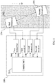
- FIG. 1 is a schematic diagram illustrating a signal processing circuit 100 used in a flow meter, according to embodiments of the present application.
- the signal processing circuit 100 is coupled to a first transducer 102 and a second transducer 104.
- the transducer is a component capable of transforming energy from one form into another form. These energy forms may include electric energy, mechanic energy, electromagnetic energy, solar energy, chemical energy, acoustic energy and thermal energy, etc.; however, the present application is not limited thereto, and the transducer may include any component capable of transforming energy.
- the first transducer 102 and the second transducer 104 are disposed in a pipeline 116, and the transmission direction of the first transducer 102 faces the second transducer 104; the transmission direction of the second transducer 104 faces the first transducer 102.
- Fluid such as, liquid or gas having the flow velocity v flows along the disposition direction D of the pipeline 116 and passes sequentially through the first transducer 102 and the second transducer 104.
- the signal processing circuit 100 includes a first transmitter 106 and a first receiver 108, both of which are coupled to a first transducer 102; and a second transmitter 110 and a second receiver 112, both of which are coupled to a second transducer 104.
- the signal processing circuit 100 further includes a control unit 114 coupled to the first transmitter 106, the first receiver 108, the second transmitter 110 and the second receiver 112.
- the signal processing circuit 100 is configured to generate a current acoustic speed c and a current temperature T according to the results obtained from the first transducer 102 and the second transducer 104.
- FIG. 2 and FIG. 3 flow diagrams illustrating the process that the control unit 114 calculates a current acoustic speed c according to the first embodiment of the present application.
- the flow velocity v is controlled, and hence, has a known value; during a general stage (Step 214 to Step 220 in FIG. 3 ) of the flow meter, the value of the flow velocity v is unknown.
- the signal processing circuit 100 is used to obtain the distance L between the first transducer 102 and the second transducer 104.
- Step 202 to Step 212 can be used to obtain a more accurate distance L so that in Step 214 to Step 220, it is feasible to estimate the current acoustic speed c and the current temperature T.
- Step 202 the flow velocity v of the fluid in the pipeline 116 is controlled at 0, meaning that the fluid is not flowing.
- Step 206 it is feasible to obtain specific factor t TX 2 + t RX 21 - t TX 1 - t RX 12 by subtracting a first delay time TM12 from the second delay time TM21 for subsequent use.
- TM 21 ⁇ TM 12 t TX 2 + t RX 21 ⁇ t TX 1 ⁇ t RX 12
- equation (6) can be obtained according to equation (4) and equation (5): L ⁇ 2 ⁇ vs ⁇ TM 12 vs ⁇ TM 21 vs / TM 21 vs ⁇ TM 12 vs ⁇ t TX 2 + t RX 21 ⁇ t TX 1 ⁇ t RX 12
- Step 212 it is feasible to obtain the distance L according to the specific flow velocity vs, the specific factor t TX 2 + t RX 21 - t TX 1 - t RX 12 , the third delay time TM12 vs and the fourth delay time TM21 vs from the equation (6).
- equation (9) can be obtained according to equation (7) and equation (8): c ⁇ L / 2 ⁇ TM 12 v + TM 21 v / TM 21 v ⁇ TM 12 v
- Step 218 it is feasible to obtain the current acoustic speed c according to the distance L, the fifth delay time TM12 v , and the sixth delay time TM21 v from equation (9).
- c 343 + 0.6 ⁇ T
- Step 220 the control unit 114 further obtains the current temperature T according to the current acoustic speed c from equation (10).
- FIG. 4 is a flow diagram illustrating the process that the control unit 114 calculates the current acoustic speed c, according to the second embodiment of the present application.
- the flow meter enters the general stage, at which time the flow velocity v is unknown.
- Step 314 to Step 320 in FIG. 4 can be used in connection with Step 202 to Step 212 in FIG. 2 .
- Step 214 to Step 220 in FIG. 3 may replace Step 314 to Step 320 in FIG. 4 , so as to estimate the current acoustic speed c and the current temperature T more accurately.
- Equation (12) TE 12 v ⁇ TM 12 v ⁇ 2 ⁇ L / c
- Step 318 the control unit 114 can obtain the current acoustic speed c according to the distance L, the seventh delay time TM12 v , and the eighth delay time TE12 v from equation (13).
- Step 320 the control unit 114 further obtain the current temperature T according to the current acoustic speed c from equation (10).
- the flow velocity v is relatively small, and hence, the degree of distortion during the simplification process of equation (13) is less than that of the equation (9), and accordingly, the current acoustic speed c and the current temperature T obtained in Step 314 to Step 320 are more accurate than those obtained in Step 214 to Step 220.
- FIG. 5 is a flow diagram illustrating the process that control unit 114 calculates the current acoustic speed c, according to the third embodiment of the present application.
- the flow meter enters a general stage, at which time, the flow velocity v is an unknown value.
- Step 514 to Step 420 in FIG. 5 can be used in connection with Step 202 to Step 212 in FIG. 2 .
- Step 214 to Step 220 in FIG. 3 may replace Step 414 to Step 420 in FIG. 5 , so as to estimate the current acoustic speed c and the current temperature T more accurately.
- the control unit 114 can obtain the current acoustic speed c according to the distance L, the ninth delay time TM12 v , the tenth delay time TM21 v , the eleventh delay time TE11 v , and the twelfth delay time TE22 v from equation (20).
- Step 424 the control unit 114 further obtain the current temperature T according to the current acoustic speed c from equation (10).
Landscapes
- Physics & Mathematics (AREA)
- Fluid Mechanics (AREA)
- General Physics & Mathematics (AREA)
- Electromagnetism (AREA)
- Measuring Volume Flow (AREA)
- Length Measuring Devices Characterised By Use Of Acoustic Means (AREA)
Abstract
Description
- The present application relates generally to a signal processing circuit and provides a related chip, a flow meter and a method.
- Ultrasonic flow meter is a commonly used flow meter. Flow meters are widely used to detect the flow velocity of fluids. Compared with other types of flow meters, ultrasonic flow meters are advantageous in terms of pressure loss, minimum detectable flow rate and installation cost, among the others; however, the accuracy thereof still needs to be improved, and further improvements and innovations are needed.
- One purpose of the present application is directed to a signal processing circuit and a related chip, a flow meter and a method for processing a transducer receiving signal, so as to address the above-mentioned issues.
- One embodiment of the present application discloses a signal processing circuit, which is coupled to a first transducer and a second transducer, wherein there is a distance greater than zero between the first transducer and the second transducer, and a fluid having a flow velocity flows sequentially through the first transducer and the second transducer, and the signal processing circuit includes: a first transmitter, coupled to the first transducer; a first receiver, coupled to the first transducer; a second transmitter, coupled to the second transducer; a second receiver, coupled to the second transducer; and a control unit, coupled to the first transmitter, the first receiver, the second transmitter and the second receiver, wherein the control unit is configured to: generate a first signal and determine a first delay time for the first signal passing through the first transmitter and the first transducer to the second transducer and then passing through the second receiver, when the flow velocity is zero; generate a second signal and determine a second delay time for the second signal passing through the second transmitter and the second transducer to the first transducer and then passing through the first receiver, when the flow velocity is zero; obtain a specific factor according to the first delay time and the second delay time; generate a third signal and determine a third delay time for the third signal passing through the first transmitter and the first transducer to the second transducer and then passing through the second receiver, when the flow velocity is a specific flow velocity greater than zero; generate a fourth signal and determine a fourth delay time for the fourth signal passing through the second transmitter and the second transducer to the first transducer and then passing through the first receiver, when the flow velocity is the specific flow velocity; and obtain the distance according to the specific flow velocity, the specific factor, the third delay time and the fourth delay time.
- One embodiment of the present application discloses a chip, which includes the above signal processing circuit.
- One embodiment of the present application discloses a flow meter, which includes the above signal processing circuit; the above first transducer; and the above second transducer; wherein the signal processing circuit is coupled to the first transducer and the second transducer.
- One embodiment of the present application discloses a signal processing method, which is configured to control a first transmitter, a first receiver, a second transmitter and a second receiver, wherein the first transmitter and the first receiver are coupled to a first transducer, the second transmitter and the second receiver are coupled to a second transducer, there is a distance greater than zero between the first transducer and the second transducer, and a fluid having a flow velocity flows sequentially through the first transducer and the second transducer, wherein the signal processing method includes: generating a first signal and determining a first delay time for the first signal passing through the first transmitter and the first transducer to the second transducer and then passing through the second receiver, when the flow velocity is zero; generating a second signal and determining a second delay time for the second signal passing through the second transmitter and the second transducer to the first transducer and then passing through the first receiver, when the flow velocity is zero; obtaining a specific factor according to the first delay time and the second delay time; generating a third signal and determining a third delay time for the third signal passing through the first transmitter and the first transducer to the second transducer and then passing through the second receiver, when the flow velocity is a specific flow velocity greater than zero; generating a fourth signal and determining a fourth delay time for the fourth signal passing through the second transmitter and the second transducer to the first transducer and then passing through the first receiver, when the flow velocity is the specific flow velocity; and obtaining the distance according to the specific flow velocity, the specific factor, the third delay time and the fourth delay time.
- The present application provides signal processing circuits and a related chip, a flow meter and a method for processing the transducer receive signal can improve the accuracy of the flow meter.
-
-
FIG. 1 is a schematic diagram illustrating a signal processing circuit for use in a flow meter, according to embodiments of the present application. -
FIG. 2 is a flow diagram illustrating the process that the control unit calculates the distance between a first transducer and a second transducer, according to embodiments of the present application. -
FIG. 3 is a flow diagram illustrating a process that the control unit calculates a current acoustic speed, according to the first embodiment of the present application. -
FIG. 4 is a flow diagram illustrating a process that the control unit calculates a current acoustic speed, according to the second embodiment of the present application. -
FIG. 5 is a flow diagram illustrating a process that the control unit calculates a current acoustic speed, according to the third embodiment of the present application. - Reference numerals used is the drawings are summarized below:
- 100
- Signal processing circuit
- 102, 104
- Transducer
- 106, 110
- Transmitter
- 108, 112
- Receiver
- 114
- Control unit
- 202∼220, 314∼320, 414∼424
- Steps
- The following disclosure provides many different embodiments, or examples, for implementing different features of the application. Specific examples of components and arrangements are described below to simplify the present disclosure. These are, of course, merely examples and are not intended to be limiting. For example, the formation of a first feature over or on a second feature in the description that follows may include embodiments in which the first and the second features are formed in direct contact, and may also include embodiments in which additional features may be formed between the first and the second features, such that the first and the second features may not be in direct contact. In addition, the present disclosure may repeat reference numerals and/or letters in the various examples. This repetition is for the purpose of simplicity and clarity and does not in itself dictate a relationship between the various embodiments and/or configurations discussed.
- Further, spatially relative terms, such as "beneath, " "below, " "lower, " "above, " "upper" and the like, may be used herein for the ease of the description to describe one element or feature's relationship with respect to another element(s) or feature(s) as illustrated in the drawings. The spatially relative terms are intended to encompass different orientations of the device in use or operation in addition to the orientation depicted in the figures. The apparatus may be otherwise oriented (e.g., rotated by 90 degrees or at other orientations) and the spatially relative descriptors used herein may likewise be interpreted accordingly.
- Notwithstanding that the numerical ranges and parameters setting forth the broad scope of the application are approximations, the numerical values set forth in the specific examples are reported as precisely as possible. Any numerical value, however, inherently contains certain errors necessarily resulting from the standard deviation found in the respective testing measurements. Also, as used herein, the term "about" generally means within 10%, 5%, 1%, or 0.5% of a given value or range. Alternatively, the term "about" means within an acceptable standard error of the mean when considered by one of ordinary skill in the art. As could be appreciated, other than in the operating/working examples, or unless otherwise expressly specified, all of the numerical ranges, amounts, values and percentages such as those for quantities of materials, durations of times, temperatures, operating conditions, ratios of amounts, and the likes thereof disclosed herein should be understood as modified in all instances by the term "about." Accordingly, unless indicated to the contrary, the numerical parameters set forth in the present disclosure and attached claims are approximations that can vary as desired. At the very least, each numerical parameter should at least be construed in light of the number of reported significant digits and by applying ordinary rounding techniques. Ranges can be expressed herein as from one endpoint to another endpoint or between two endpoints. All ranges disclosed herein are inclusive of the endpoints, unless specified otherwise.
- When calculating the flow rate, it is critical to determine whether the detected data make sense so as to determine whether there is a need to calibrate the system. In some embodiments, the acoustic speed can be used as the basis for such determination, for example, one can apply the temperature value measured by the temperature sensor to obtain a theoretical acoustic speed, which is then used as a comparison with the current acoustic speed estimated from the actual measurement, so as to monitor whether the ultrasonic flow meter and temperature sensor of the system operate normally.
- The present application provides a
signal processing circuit 100 configured to calculate a current acoustic speed c and a current temperature T; the present application also provides a chip, which includes thesignal processing circuit 100. In some embodiments, thesignal processing circuit 100 can be used in a transducer device; for example, the present application also provides a flow meter, which includes thesignal processing circuit 100 and atransducer 102. For example, said flow meter can be used to detect flow velocity and/or flow rate of gases or liquids, however, the present application is not limited thereto. -
FIG. 1 is a schematic diagram illustrating asignal processing circuit 100 used in a flow meter, according to embodiments of the present application. Thesignal processing circuit 100 is coupled to afirst transducer 102 and asecond transducer 104. The transducer is a component capable of transforming energy from one form into another form. These energy forms may include electric energy, mechanic energy, electromagnetic energy, solar energy, chemical energy, acoustic energy and thermal energy, etc.; however, the present application is not limited thereto, and the transducer may include any component capable of transforming energy. - The
first transducer 102 and thesecond transducer 104 are disposed in apipeline 116, and the transmission direction of thefirst transducer 102 faces thesecond transducer 104; the transmission direction of thesecond transducer 104 faces thefirst transducer 102. There is a distance L between thefirst transducer 102 and thesecond transducer 104, and L is greater than zero. Fluid (such as, liquid or gas) having the flow velocity v flows along the disposition direction D of thepipeline 116 and passes sequentially through thefirst transducer 102 and thesecond transducer 104. - The
signal processing circuit 100 includes afirst transmitter 106 and afirst receiver 108, both of which are coupled to afirst transducer 102; and asecond transmitter 110 and asecond receiver 112, both of which are coupled to asecond transducer 104. Thesignal processing circuit 100 further includes acontrol unit 114 coupled to thefirst transmitter 106, thefirst receiver 108, thesecond transmitter 110 and thesecond receiver 112. Thesignal processing circuit 100 is configured to generate a current acoustic speed c and a current temperature T according to the results obtained from thefirst transducer 102 and thesecond transducer 104. -
FIG. 2 andFIG. 3 flow diagrams illustrating the process that thecontrol unit 114 calculates a current acoustic speed c according to the first embodiment of the present application. First, during an initializing stage (Step 202 to Step 212 inFIG. 2 ) of the flow meter, the flow velocity v is controlled, and hence, has a known value; during a general stage (Step 214 to Step 220 inFIG. 3 ) of the flow meter, the value of the flow velocity v is unknown. In the initializing stage ofStep 202 to Step 212, thesignal processing circuit 100 is used to obtain the distance L between thefirst transducer 102 and thesecond transducer 104. Although thefirst transducer 102 and thesecond transducer 104 are disposed in advanced, there might still be some minor deviation of the distance L, and hence, the initializing stage ofStep 202 to Step 212 can be used to obtain a more accurate distance L so that inStep 214 to Step 220, it is feasible to estimate the current acoustic speed c and the current temperature T. - In
Step 202, the flow velocity v of the fluid in thepipeline 116 is controlled at 0, meaning that the fluid is not flowing. Thecontrol unit 114 generates a first signal and determines a first delay time TM12 for the first signal passing through thefirst transmitter 106 and thefirst transducer 102 to directly trigger thesecond transducer 104, and then passing through asecond receiver 112, wherein the first delay time TM12 can be expressed using the following equation:
first transmitter 106 and thefirst transducer 102 transmitting the signal (such as, the first signal), tRX12 is the delay time for the signal (such as, the first signal) from thefirst transmitter 106 being received by thesecond transducer 104 and thesecond receiver 112, t12 is the time for the signal (such as, the first signal) traveling from thefirst transducer 102 to thesecond transducer 104, and c is the current acoustic speed. - Next, in
Step 204, the flow velocity v of the fluid in thepipeline 116 is still controlled at zero, and thecontrol unit 114 generates a second signal and determines a second delay time TM21 for the second signal passing through thesecond transmitter 110 and thesecond transducer 104 to directly trigger thefirst transducer 102, and then passing through afirst receiver 108, wherein the second delay time TM21 can be expressed using the following equation:
second transmitter 110 and thesecond transducer 104 transmitting the signal (such as, the second signal), tRX21 is the delay time for the signal (such as, the second signal) from thesecond transmitter 110 being received by thefirst transducer 102 and thefirst receiver 108, and t21 is the time for the signal (such as, the second signal) traveling from thesecond transducer 104 to thefirst transducer 102. - Accordingly, in
Step 206, it is feasible to obtain specific factor t TX2 + t RX21 - t TX1 - t RX12 by subtracting a first delay time TM12 from the second delay time TM21 for subsequent use.
- Next, in
Step 208, the flow velocity v of the fluid is controlled at a specific flow velocity vs that is greater than zero, and thecontrol unit 114 generates a third signal and determines a third delay time TM12vs for the third signal passing through thefirst transmitter 106 and thefirst transducer 102 to directly trigger thesecond transducer 104, and then passing through thesecond receiver 112, wherein the third delay time TM12vs can be expressed using the following equation:
- In
Step 210, the flow velocity v of the fluid is stilled controlled at the specific flow velocity vs that is greater than zero, and thecontrol unit 114 generates a fourth signal and determines a fourth delay time TM21vs for the fourth signal passing through thesecond transmitter 110 and thesecond transducer 104 to directly trigger thefirst transducer 102, and then passing through thefirst receiver 108, wherein the fourth delay time TM21vs can be expressed using the following equation:
- Therefore, equation (6) can be obtained according to equation (4) and equation (5):

- Hence, in
Step 212, it is feasible to obtain the distance L according to the specific flow velocity vs, the specific factor t TX2 + t RX21 - t TX1 - t RX12, the third delay time TM12vs and the fourth delay time TM21vs from the equation (6). - Next, in
Step 214, the flow meter enters the general stage, at which time, the flow velocity v is unknown, and thecontrol unit 114 generates a fifth signal and determines a fifth delay time TM12v for the fifth signal passing through thefirst transmitter 106 and thefirst transducer 102 to directly trigger thesecond transducer 104, and then passing through thesecond receiver 112, wherein the fifth delay time TM12v can be expressed using the following equation:
- In
Step 216, thecontrol unit 114 generates a sixth signal and determines a sixth delay time TM21v for the sixth signal passing through thesecond transmitter 110 and thesecond transducer 104 to directly trigger thefirst transducer 102, and then passing through thefirst receiver 108, wherein the sixth delay time TM21v can be expressed using the following equation:
- Therefore, equation (9) can be obtained according to equation (7) and equation (8):

- Hence, in
Step 218, it is feasible to obtain the current acoustic speed c according to the distance L, the fifth delay time TM12v, and the sixth delay time TM21v from equation (9).
- In
Step 220, thecontrol unit 114 further obtains the current temperature T according to the current acoustic speed c from equation (10). -
FIG. 4 is a flow diagram illustrating the process that thecontrol unit 114 calculates the current acoustic speed c, according to the second embodiment of the present application. InStep 314 to Step 320 inFIG. 4 , the flow meter enters the general stage, at which time the flow velocity v is unknown. Step 314 to Step 320 inFIG. 4 can be used in connection withStep 202 to Step 212 inFIG. 2 . In other words, Step 214 to Step 220 inFIG. 3 may replaceStep 314 to Step 320 inFIG. 4 , so as to estimate the current acoustic speed c and the current temperature T more accurately. - In
Step 314, the flow velocity v is unknown, and thecontrol unit 114 generates a seventh signal and determines a seventh delay time TM12v for a seventh signal passing through thefirst transmitter 106 and thefirst transducer 102 to directly trigger thesecond transducer 104, and then passing through thesecond receiver 112, wherein the seventh delay time TM12v can be expressed using the following equation (same as equation (7)):
- In
Step 316, the flow velocity v is unknown, and thecontrol unit 114 generates an eighth signal and determines an eighth delay time TE12v for the eighth signal passing through thefirst transmitter 106 and thefirst transducer 102 to thesecond transducer 104 and bouncing back to thefirst transducer 102, and then bouncing back to thesecond transducer 104, and then passing through thesecond receiver 112, wherein the eighth delay time TE12v can be expressed using the following equation:
- The following equation can be obtained by subtracting equation (11) from equation (12):

- Therefore, in
Step 318, thecontrol unit 114 can obtain the current acoustic speed c according to the distance L, the seventh delay time TM12v, and the eighth delay time TE12v from equation (13). - Subsequently, in
Step 320, thecontrol unit 114 further obtain the current temperature T according to the current acoustic speed c from equation (10). - Compared with the acoustic speed c, the flow velocity v is relatively small, and hence, the degree of distortion during the simplification process of equation (13) is less than that of the equation (9), and accordingly, the current acoustic speed c and the current temperature T obtained in
Step 314 to Step 320 are more accurate than those obtained inStep 214 to Step 220. -
FIG. 5 is a flow diagram illustrating the process that controlunit 114 calculates the current acoustic speed c, according to the third embodiment of the present application. InStep 414 to Step 420 inFIG. 5 , the flow meter enters a general stage, at which time, the flow velocity v is an unknown value. Step 514 to Step 420 inFIG. 5 can be used in connection withStep 202 to Step 212 inFIG. 2 . In other words, Step 214 to Step 220 inFIG. 3 may replaceStep 414 to Step 420 inFIG. 5 , so as to estimate the current acoustic speed c and the current temperature T more accurately. - In
Step 414, the flow velocity v is unknown, and thecontrol unit 114 generates a ninth signal and determines a ninth delay time TM12v for the ninth signal passing through thefirst transmitter 106 and thefirst transducer 102 to directly trigger thesecond transducer 104, and then passing through thesecond receiver 112, wherein the ninth delay time TM12v can be expressed using the following equation (same as equation (7)):
- In
Step 416, thecontrol unit 114 generates a tenth signal and determines a tenth delay time TM21v for the tenth signal passing through thesecond transmitter 110 and thesecond transducer 104 to directly trigger thefirst transducer 102, and then passing through thefirst receiver 108, wherein the tenth delay time TM21v can be expressed using the following equation (same as equation (8)):
- In
Step 418, thecontrol unit 114 generates an eleventh signal and determines an eleventh delay time TE11v for the eleventh signal passing through thefirst transmitter 106 and thefirst transducer 102 to thesecond transducer 104, and bouncing back to thefirst transducer 102, and then passing through thefirst transducer 102 and thefirst receiver 108, wherein the eleventh delay time TE11v can be expressed using the following equation:
first transmitter 106 in thefirst transducer 102 and thefirst receiver 108. - In
Step 420, thecontrol unit 114 generates a twelfth signal and determines a twelfth delay time TE22v for the twelfth signal passing through thesecond transmitter 110 and thesecond transducer 104 to thefirst transducer 102 and bouncing back to thesecond transducer 104, and then passing through thesecond transducer 104 and thesecond receiver 112, which can be expressed using the following equation:
second transmitter 110 in thesecond transducer 104 and thesecond receiver 112. - The following equation can be obtained by subtracting equation (14) from equation (16):

- The following equation can be obtained by subtracting equation (15) from equation (17):

- Consequently, the following equation can be obtained according to equation (18) and equation (19):

- Hence, in
Step 422, thecontrol unit 114 can obtain the current acoustic speed c according to the distance L, the ninth delay time TM12v, the tenth delay time TM21v, the eleventh delay time TE11v, and the twelfth delay time TE22v from equation (20). - Then, in
Step 424, thecontrol unit 114 further obtain the current temperature T according to the current acoustic speed c from equation (10). - The degree of simplification in equation (20) is less than that in equation (9), and therefore, the current acoustic speed c and current temperature T obtained from
Step 414 to Step 424 is more accurate than those obtained fromStep 214 to Step 220. - The foregoing outlines features of several embodiments so that those skilled in the art may better understand various aspects of the present disclosure. Those skilled in the art should appreciate that they may readily use the present disclosure as a basis for designing or modifying other processes and structures for carrying out the same purposes and/or achieving the same advantages of embodiments introduced herein. Those skilled in the art should also realize that such equivalent embodiments still fall within the spirit and scope of the present disclosure, and they may make various changes, substitutions, and alterations thereto without departing from the spirit and scope of the present disclosure.
Claims (16)
- A signal processing circuit, characterized in that the signal processing circuit is coupled to a first transducer and a second transducer, wherein there is a distance greater than zero between the first transducer and the second transducer, and a fluid having a flow velocity flows sequentially through the first transducer and the second transducer, wherein the signal processing circuit comprises:a first transmitter, coupled to the first transducer;a first receiver, coupled to the first transducer;a second transmitter, coupled to the second transducer;a second receiver, coupled to the second transducer; anda control unit, coupled to the first transmitter, the first receiver, the second transmitter and the second receiver, wherein the control unit is configured to:generate a first signal and determine a first delay time for the first signal passing through the first transmitter and the first transducer to the second transducer and then passing through the second receiver, when the flow velocity is zero;generate a second signal and determine a second delay time for the second signal passing through the second transmitter and the second transducer to the first transducer and then passing through the first receiver, when the flow velocity is zero;obtain a specific factor according to the first delay time and the second delay time;generate a third signal and determine a third delay time for the third signal passing through the first transmitter and the first transducer to the second transducer and then passing through the second receiver, when the flow velocity is a specific flow velocity greater than zero;generate a fourth signal and determine a fourth delay time for the fourth signal passing through the second transmitter and the second transducer to the first transducer and then passing through the first receiver, when the flow velocity is the specific flow velocity; andobtain the distance according to the specific flow velocity, the specific factor, the third delay time and the fourth delay time.
- The signal processing circuit of claim 1, characterized in that the control unit is further configured to:generate a fifth signal and determine a fifth delay time for the fifth signal passing through the first transmitter and the first transducer to the second transducer and then passing through the second receiver;generate a sixth signal and determine a sixth delay time for the sixth signal passing through the second transmitter and the second transducer to the first transducer and then passing through the first receiver; andobtain a current acoustic speed according to the distance, the fifth delay time and the sixth delay time.
- The signal processing circuit of claim 1, characterized in that the control unit is further configured to:generate a seventh signal and determine a seventh delay time for the seventh signal passing through the first transmitter and the first transducer to the second transducer and then passing through the second receiver;generate an eighth signal and determine an eighth delay time for the eighth signal passing through the first transmitter and the first transducer to the second transducer and bouncing back to the first transducer, and then bouncing back to the second transducer, and then passing through the second transducer and the second receiver; andobtain a current acoustic speed according to the distance, the seventh delay time and the eighth delay time.
- The signal processing circuit of claim 1, characterized in that the control unit is further configured to:generate a ninth signal and determine a ninth delay time for the ninth signal passing through the first transmitter and the first transducer to the second transducer and then passing through the second receiver;generate a tenth signal and determine a tenth delay time for the tenth signal passing through a second transmitter and the second transducer to the first transducer and then passing through the first receiver;generate an eleventh signal and determine an eleventh delay time for the eleventh signal passing through the first transmitter and the first transducer to the second transducer and bouncing back to the first transducer, and then passing through the first transducer and the first receiver;generate a twelfth signal and determine a twelfth delay time for the twelfth signal passing through the second transmitter and the second transducer to the first transducer and bouncing back to the second transducer, and then passing through the second transducer and the second receiver; andobtain a current acoustic speed according to the distance, the ninth delay time, the tenth delay time, the eleventh delay time and the twelfth delay time.
- The signal processing circuit of any of claims 2-4, characterized in that the control unit is further configured to obtain a current temperature according to the current acoustic speed.
- The signal processing circuit of claim 1, characterized in that the control unit is further configured to obtain the specific factor by subtracting the first delay time from the second delay time.
- The signal processing circuit of claim 6, characterized in that the specific factor is a delay time for the second signal passing through the second transmitter and the second transducer, plus a delay time for the second signal passing through the first transducer and the first receiver, minus a delay time for the first signal passing through the first transmitter and the first transducer, and minus a delay time for the first signal passing through the second transducer and the second receiver.
- A chip, characterized by comprising:
the signal processing circuit of any of claims 1-7. - A flow meter, characterized by comprising:the signal processing circuit of any of claims 1-7;the first transducer; andthe second transducer;wherein the signal processing circuit is coupled to the first transducer and the second transducer.
- A signal processing method, characterized by being configured to control a first transmitter, a first receiver, a second transmitter and a second receiver, wherein the first transmitter and the first receiver are coupled to a first transducer, the second transmitter and the second receiver are coupled to a second transducer, there is a distance greater than zero between the first transducer and the second transducer, and a fluid having a flow velocity flows sequentially through the first transducer and the second transducer, wherein the signal processing method comprises:generating a first signal and determining a first delay time for the first signal passing through the first transmitter and the first transducer to the second transducer and then passing through the second receiver, when the flow velocity is zero;generating a second signal and determining a second delay time for the second signal passing through the second transmitter and the second transducer to the first transducer and then passing through the first receiver, when the flow velocity is zero;obtaining a specific factor according to the first delay time and the second delay time;generating a third signal and determining a third delay time for the third signal passing through the first transmitter and the first transducer to the second transducer and then passing through the second receiver, when the flow velocity is a specific flow velocity greater than zero;generating a fourth signal and determining a fourth delay time for the fourth signal passing through the second transmitter and the second transducer to the first transducer and then passing through the first receiver, when the flow velocity is the specific flow velocity; andobtaining the distance according to the specific flow velocity, the specific factor, the third delay time and the fourth delay time.
- The signal processing method of claim 10, characterized by further comprising:generating a fifth signal and determining a fifth delay time for the fifth signal passing through the first transmitter and the first transducer to the second transducer and then passing through the second receiver;generating a sixth signal and determining a sixth delay time for the sixth signal passing through the second transmitter and the second transducer to the first transducer and then passing through the first receiver; andobtaining a current acoustic speed according to the distance, the fifth delay time and the sixth delay time.
- The signal processing method of claim 10, characterized by further comprising:generating a seventh signal and determining a seventh delay time for the seventh signal passing through the first transmitter and the first transducer to the second transducer and then passing through the second receiver;generating an eighth signal and determining an eighth delay time for the eighth signal passing through the first transmitter and the first transducer to the second transducer and bouncing back to the first transducer, and then bouncing back to the second transducer, and then passing through the second transducer and the second receiver; andobtaining a current acoustic speed according to the distance, the seventh delay time and the eighth delay time.
- The signal processing method of claim 10, characterized by further comprising:generating a ninth signal and determining a ninth delay time for the ninth signal passing through the first transmitter and the first transducer to the second transducer and then passing through the second receiver;generating a tenth signal and determining a tenth delay time for the tenth signal passing through a second transmitter and the second transducer to the first transducer and then passing through the first receiver;generating an eleventh signal and determining an eleventh delay time for the eleventh signal passing through the first transmitter and the first transducer to the second transducer and bouncing back to the first transducer, and then passing through the first transducer and the first receiver;generating a twelfth signal and determining a twelfth delay time for the twelfth signal passing through the second transmitter and the second transducer to the first transducer and bouncing back to the second transducer, and then passing through the second transducer and the second receiver; andobtaining a current acoustic speed according to the distance, the ninth delay time, the tenth delay time, the eleventh delay time and the twelfth delay time.
- The signal processing method of any of claims 11 to 13, characterized by further comprising:
obtaining a current temperature according to the current acoustic speed. - The signal processing method of claim 10, characterized by further comprising subtracting the first delay time from the second delay time to obtain the specific factor.
- The signal processing method of claim 15, characterized in that the specific factor is a delay time for the second signal passing through the second transmitter and the second transducer, plus a delay time for the second signal passing through the first transducer and the first receiver, minus a delay time for the first signal passing through the first transmitter and the first transducer, and minus a delay time for the first signal passing through the second transducer and the second receiver.
Applications Claiming Priority (1)
| Application Number | Priority Date | Filing Date | Title |
|---|---|---|---|
| PCT/CN2019/074368 WO2020155085A1 (en) | 2019-02-01 | 2019-02-01 | Signal processing circuit, and related chip, flowmeter and method |
Publications (3)
| Publication Number | Publication Date |
|---|---|
| EP3719451A1 true EP3719451A1 (en) | 2020-10-07 |
| EP3719451A4 EP3719451A4 (en) | 2021-08-25 |
| EP3719451B1 EP3719451B1 (en) | 2023-09-13 |
Family
ID=66979134
Family Applications (1)
| Application Number | Title | Priority Date | Filing Date |
|---|---|---|---|
| EP19888241.7A Active EP3719451B1 (en) | 2019-02-01 | 2019-02-01 | Signal processing circuit, and related chip, flowmeter and method |
Country Status (5)
| Country | Link |
|---|---|
| US (1) | US11428555B2 (en) |
| EP (1) | EP3719451B1 (en) |
| JP (1) | JP6902169B2 (en) |
| CN (1) | CN109923377B (en) |
| WO (1) | WO2020155085A1 (en) |
Family Cites Families (11)
| Publication number | Priority date | Publication date | Assignee | Title |
|---|---|---|---|---|
| TW283763B (en) * | 1992-10-06 | 1996-08-21 | Caldon Inc | |
| US5650571A (en) * | 1995-03-13 | 1997-07-22 | Freud; Paul J. | Low power signal processing and measurement apparatus |
| FR2803032B1 (en) * | 1999-12-28 | 2002-06-07 | Gaz De France | METHOD AND DEVICE FOR MEASURING A FLOW OF FLUID FLOWING IN A PIPELINE |
| JP3716274B2 (en) * | 2002-11-26 | 2005-11-16 | 松下電器産業株式会社 | Ultrasonic flow meter and ultrasonic flow measurement method |
| US7124621B2 (en) * | 2004-07-21 | 2006-10-24 | Horiba Instruments, Inc. | Acoustic flowmeter calibration method |
| US8746062B2 (en) * | 2010-06-29 | 2014-06-10 | Orthosensor Inc. | Medical measurement system and method |
| AU2015221509B2 (en) * | 2009-08-18 | 2017-07-20 | Rubicon Research Pty Ltd | Flow meter assembly, gate assemblies and methods of flow measurement |
| US20120272748A1 (en) * | 2010-01-07 | 2012-11-01 | Panasonic Corporation | Ultrasonic flowmeter |
| CN106932040B (en) * | 2017-03-14 | 2019-06-21 | 浙江正泰仪器仪表有限责任公司 | A kind of metering method of gas flow |
| CN108458759A (en) * | 2018-01-25 | 2018-08-28 | 陈兵 | Measure ultrasonic flowmeter signal delay time, flow method and processing unit |
| EP3814723A4 (en) * | 2018-06-27 | 2022-04-27 | Services Pétroliers Schlumberger | APPARATUS FOR MEASURING MULTI-PHASE FLUID FLOW AND RELATED METHODS |
-
2019
- 2019-02-01 CN CN201980000249.3A patent/CN109923377B/en active Active
- 2019-02-01 JP JP2020536554A patent/JP6902169B2/en not_active Expired - Fee Related
- 2019-02-01 WO PCT/CN2019/074368 patent/WO2020155085A1/en not_active Ceased
- 2019-02-01 EP EP19888241.7A patent/EP3719451B1/en active Active
-
2020
- 2020-06-01 US US16/889,342 patent/US11428555B2/en active Active
Also Published As
| Publication number | Publication date |
|---|---|
| CN109923377A (en) | 2019-06-21 |
| EP3719451A4 (en) | 2021-08-25 |
| US20200300678A1 (en) | 2020-09-24 |
| JP6902169B2 (en) | 2021-07-14 |
| CN109923377B (en) | 2021-01-29 |
| JP2021515182A (en) | 2021-06-17 |
| US11428555B2 (en) | 2022-08-30 |
| WO2020155085A1 (en) | 2020-08-06 |
| EP3719451B1 (en) | 2023-09-13 |
Similar Documents
| Publication | Publication Date | Title |
|---|---|---|
| EP2893304B1 (en) | Ultrasonic flow metering using compensated computed temperature | |
| CN103344288B (en) | A kind of transit-time ultrasonic flow meter measuring method analyzed based on zero point | |
| US9366556B2 (en) | Method for ultrasonic metering using an orifice meter fitting | |
| US20160313160A1 (en) | Apparatus and method for determining concentrations of components of a gas mixture | |
| EP3535551B1 (en) | Improvements in or relating to the monitoring of fluid flow | |
| CN103308105B (en) | Ultrasonic measurement equipment | |
| US20130081477A1 (en) | Flow meter device | |
| US20210003436A1 (en) | Time-of-flight generating circuit and chip, flow meter and method of the same | |
| US6816808B2 (en) | Peak switch detector for transit time ultrasonic meters | |
| US8950273B2 (en) | Method and thermal, flow measuring device for determining and/or monitoring at least one variable dependent on at least the chemical composition of a measured medium | |
| US11441933B2 (en) | Signal processing circuit and related chip, flow meter and method | |
| EP3719451B1 (en) | Signal processing circuit, and related chip, flowmeter and method | |
| EP2443422A1 (en) | Device for volume measuring and quality control of liquid fuel | |
| CN219810960U (en) | Monitoring device for liquid flow velocity in pipeline | |
| CN100593761C (en) | Ultrasonic metrology system and method for detecting peak selection errors in waveforms | |
| CN116295678A (en) | Flow measurement method, device, electronic equipment and storage medium for fluid in pipeline | |
| CN107884755A (en) | A kind of method and analogue means that analog signal is provided for radar meter | |
| EP4679041A1 (en) | Method of and device for determining a flow velocity of a liquid medium | |
| US11740112B2 (en) | Method of measuring the speed of a fluid | |
| Shinoda et al. | Real-time measurement of multi-point distance and displacement by Fourier transform technique using optical frequency modulation |
Legal Events
| Date | Code | Title | Description |
|---|---|---|---|
| STAA | Information on the status of an ep patent application or granted ep patent |
Free format text: STATUS: UNKNOWN |
|
| STAA | Information on the status of an ep patent application or granted ep patent |
Free format text: STATUS: THE INTERNATIONAL PUBLICATION HAS BEEN MADE |
|
| PUAI | Public reference made under article 153(3) epc to a published international application that has entered the european phase |
Free format text: ORIGINAL CODE: 0009012 |
|
| STAA | Information on the status of an ep patent application or granted ep patent |
Free format text: STATUS: REQUEST FOR EXAMINATION WAS MADE |
|
| 17P | Request for examination filed |
Effective date: 20200616 |
|
| AK | Designated contracting states |
Kind code of ref document: A1 Designated state(s): AL AT BE BG CH CY CZ DE DK EE ES FI FR GB GR HR HU IE IS IT LI LT LU LV MC MK MT NL NO PL PT RO RS SE SI SK SM TR |
|
| AX | Request for extension of the european patent |
Extension state: BA ME |
|
| A4 | Supplementary search report drawn up and despatched |
Effective date: 20210726 |
|
| RIC1 | Information provided on ipc code assigned before grant |
Ipc: G01F 1/66 20060101AFI20210720BHEP Ipc: G01F 15/02 20060101ALI20210720BHEP Ipc: G01F 25/00 20060101ALI20210720BHEP |
|
| DAV | Request for validation of the european patent (deleted) | ||
| DAX | Request for extension of the european patent (deleted) | ||
| GRAP | Despatch of communication of intention to grant a patent |
Free format text: ORIGINAL CODE: EPIDOSNIGR1 |
|
| STAA | Information on the status of an ep patent application or granted ep patent |
Free format text: STATUS: GRANT OF PATENT IS INTENDED |
|
| RIC1 | Information provided on ipc code assigned before grant |
Ipc: G01F 25/10 20220101ALI20230323BHEP Ipc: G01F 1/667 20220101ALI20230323BHEP Ipc: G01F 25/00 20060101ALI20230323BHEP Ipc: G01F 15/02 20060101ALI20230323BHEP Ipc: G01F 1/66 20060101AFI20230323BHEP |
|
| INTG | Intention to grant announced |
Effective date: 20230417 |
|
| GRAS | Grant fee paid |
Free format text: ORIGINAL CODE: EPIDOSNIGR3 |
|
| GRAA | (expected) grant |
Free format text: ORIGINAL CODE: 0009210 |
|
| STAA | Information on the status of an ep patent application or granted ep patent |
Free format text: STATUS: THE PATENT HAS BEEN GRANTED |
|
| AK | Designated contracting states |
Kind code of ref document: B1 Designated state(s): AL AT BE BG CH CY CZ DE DK EE ES FI FR GB GR HR HU IE IS IT LI LT LU LV MC MK MT NL NO PL PT RO RS SE SI SK SM TR |
|
| REG | Reference to a national code |
Ref country code: CH Ref legal event code: EP |
|
| REG | Reference to a national code |
Ref country code: DE Ref legal event code: R096 Ref document number: 602019037621 Country of ref document: DE |
|
| REG | Reference to a national code |
Ref country code: IE Ref legal event code: FG4D |
|
| REG | Reference to a national code |
Ref country code: LT Ref legal event code: MG9D |
|
| REG | Reference to a national code |
Ref country code: NL Ref legal event code: MP Effective date: 20230913 |
|
| PG25 | Lapsed in a contracting state [announced via postgrant information from national office to epo] |
Ref country code: GR Free format text: LAPSE BECAUSE OF FAILURE TO SUBMIT A TRANSLATION OF THE DESCRIPTION OR TO PAY THE FEE WITHIN THE PRESCRIBED TIME-LIMIT Effective date: 20231214 |
|
| PG25 | Lapsed in a contracting state [announced via postgrant information from national office to epo] |
Ref country code: SE Free format text: LAPSE BECAUSE OF FAILURE TO SUBMIT A TRANSLATION OF THE DESCRIPTION OR TO PAY THE FEE WITHIN THE PRESCRIBED TIME-LIMIT Effective date: 20230913 Ref country code: RS Free format text: LAPSE BECAUSE OF FAILURE TO SUBMIT A TRANSLATION OF THE DESCRIPTION OR TO PAY THE FEE WITHIN THE PRESCRIBED TIME-LIMIT Effective date: 20230913 Ref country code: NO Free format text: LAPSE BECAUSE OF FAILURE TO SUBMIT A TRANSLATION OF THE DESCRIPTION OR TO PAY THE FEE WITHIN THE PRESCRIBED TIME-LIMIT Effective date: 20231213 Ref country code: LV Free format text: LAPSE BECAUSE OF FAILURE TO SUBMIT A TRANSLATION OF THE DESCRIPTION OR TO PAY THE FEE WITHIN THE PRESCRIBED TIME-LIMIT Effective date: 20230913 Ref country code: LT Free format text: LAPSE BECAUSE OF FAILURE TO SUBMIT A TRANSLATION OF THE DESCRIPTION OR TO PAY THE FEE WITHIN THE PRESCRIBED TIME-LIMIT Effective date: 20230913 Ref country code: HR Free format text: LAPSE BECAUSE OF FAILURE TO SUBMIT A TRANSLATION OF THE DESCRIPTION OR TO PAY THE FEE WITHIN THE PRESCRIBED TIME-LIMIT Effective date: 20230913 Ref country code: GR Free format text: LAPSE BECAUSE OF FAILURE TO SUBMIT A TRANSLATION OF THE DESCRIPTION OR TO PAY THE FEE WITHIN THE PRESCRIBED TIME-LIMIT Effective date: 20231214 Ref country code: FI Free format text: LAPSE BECAUSE OF FAILURE TO SUBMIT A TRANSLATION OF THE DESCRIPTION OR TO PAY THE FEE WITHIN THE PRESCRIBED TIME-LIMIT Effective date: 20230913 |
|
| REG | Reference to a national code |
Ref country code: AT Ref legal event code: MK05 Ref document number: 1611716 Country of ref document: AT Kind code of ref document: T Effective date: 20230913 |
|
| PG25 | Lapsed in a contracting state [announced via postgrant information from national office to epo] |
Ref country code: NL Free format text: LAPSE BECAUSE OF FAILURE TO SUBMIT A TRANSLATION OF THE DESCRIPTION OR TO PAY THE FEE WITHIN THE PRESCRIBED TIME-LIMIT Effective date: 20230913 |
|
| PG25 | Lapsed in a contracting state [announced via postgrant information from national office to epo] |
Ref country code: IS Free format text: LAPSE BECAUSE OF FAILURE TO SUBMIT A TRANSLATION OF THE DESCRIPTION OR TO PAY THE FEE WITHIN THE PRESCRIBED TIME-LIMIT Effective date: 20240113 |
|
| PG25 | Lapsed in a contracting state [announced via postgrant information from national office to epo] |
Ref country code: AT Free format text: LAPSE BECAUSE OF FAILURE TO SUBMIT A TRANSLATION OF THE DESCRIPTION OR TO PAY THE FEE WITHIN THE PRESCRIBED TIME-LIMIT Effective date: 20230913 |
|
| PG25 | Lapsed in a contracting state [announced via postgrant information from national office to epo] |
Ref country code: ES Free format text: LAPSE BECAUSE OF FAILURE TO SUBMIT A TRANSLATION OF THE DESCRIPTION OR TO PAY THE FEE WITHIN THE PRESCRIBED TIME-LIMIT Effective date: 20230913 |
|
| PG25 | Lapsed in a contracting state [announced via postgrant information from national office to epo] |
Ref country code: SM Free format text: LAPSE BECAUSE OF FAILURE TO SUBMIT A TRANSLATION OF THE DESCRIPTION OR TO PAY THE FEE WITHIN THE PRESCRIBED TIME-LIMIT Effective date: 20230913 Ref country code: RO Free format text: LAPSE BECAUSE OF FAILURE TO SUBMIT A TRANSLATION OF THE DESCRIPTION OR TO PAY THE FEE WITHIN THE PRESCRIBED TIME-LIMIT Effective date: 20230913 Ref country code: IS Free format text: LAPSE BECAUSE OF FAILURE TO SUBMIT A TRANSLATION OF THE DESCRIPTION OR TO PAY THE FEE WITHIN THE PRESCRIBED TIME-LIMIT Effective date: 20240113 Ref country code: ES Free format text: LAPSE BECAUSE OF FAILURE TO SUBMIT A TRANSLATION OF THE DESCRIPTION OR TO PAY THE FEE WITHIN THE PRESCRIBED TIME-LIMIT Effective date: 20230913 Ref country code: EE Free format text: LAPSE BECAUSE OF FAILURE TO SUBMIT A TRANSLATION OF THE DESCRIPTION OR TO PAY THE FEE WITHIN THE PRESCRIBED TIME-LIMIT Effective date: 20230913 Ref country code: CZ Free format text: LAPSE BECAUSE OF FAILURE TO SUBMIT A TRANSLATION OF THE DESCRIPTION OR TO PAY THE FEE WITHIN THE PRESCRIBED TIME-LIMIT Effective date: 20230913 Ref country code: AT Free format text: LAPSE BECAUSE OF FAILURE TO SUBMIT A TRANSLATION OF THE DESCRIPTION OR TO PAY THE FEE WITHIN THE PRESCRIBED TIME-LIMIT Effective date: 20230913 Ref country code: PT Free format text: LAPSE BECAUSE OF FAILURE TO SUBMIT A TRANSLATION OF THE DESCRIPTION OR TO PAY THE FEE WITHIN THE PRESCRIBED TIME-LIMIT Effective date: 20240115 Ref country code: SK Free format text: LAPSE BECAUSE OF FAILURE TO SUBMIT A TRANSLATION OF THE DESCRIPTION OR TO PAY THE FEE WITHIN THE PRESCRIBED TIME-LIMIT Effective date: 20230913 |
|
| PG25 | Lapsed in a contracting state [announced via postgrant information from national office to epo] |
Ref country code: PL Free format text: LAPSE BECAUSE OF FAILURE TO SUBMIT A TRANSLATION OF THE DESCRIPTION OR TO PAY THE FEE WITHIN THE PRESCRIBED TIME-LIMIT Effective date: 20230913 Ref country code: IT Free format text: LAPSE BECAUSE OF FAILURE TO SUBMIT A TRANSLATION OF THE DESCRIPTION OR TO PAY THE FEE WITHIN THE PRESCRIBED TIME-LIMIT Effective date: 20230913 |
|
| REG | Reference to a national code |
Ref country code: DE Ref legal event code: R097 Ref document number: 602019037621 Country of ref document: DE |
|
| PG25 | Lapsed in a contracting state [announced via postgrant information from national office to epo] |
Ref country code: DK Free format text: LAPSE BECAUSE OF FAILURE TO SUBMIT A TRANSLATION OF THE DESCRIPTION OR TO PAY THE FEE WITHIN THE PRESCRIBED TIME-LIMIT Effective date: 20230913 |
|
| PLBE | No opposition filed within time limit |
Free format text: ORIGINAL CODE: 0009261 |
|
| STAA | Information on the status of an ep patent application or granted ep patent |
Free format text: STATUS: NO OPPOSITION FILED WITHIN TIME LIMIT |
|
| PG25 | Lapsed in a contracting state [announced via postgrant information from national office to epo] |
Ref country code: DK Free format text: LAPSE BECAUSE OF FAILURE TO SUBMIT A TRANSLATION OF THE DESCRIPTION OR TO PAY THE FEE WITHIN THE PRESCRIBED TIME-LIMIT Effective date: 20230913 |
|
| 26N | No opposition filed |
Effective date: 20240614 |
|
| REG | Reference to a national code |
Ref country code: DE Ref legal event code: R119 Ref document number: 602019037621 Country of ref document: DE |
|
| PG25 | Lapsed in a contracting state [announced via postgrant information from national office to epo] |
Ref country code: MC Free format text: LAPSE BECAUSE OF FAILURE TO SUBMIT A TRANSLATION OF THE DESCRIPTION OR TO PAY THE FEE WITHIN THE PRESCRIBED TIME-LIMIT Effective date: 20230913 |
|
| REG | Reference to a national code |
Ref country code: CH Ref legal event code: PL |
|
| PG25 | Lapsed in a contracting state [announced via postgrant information from national office to epo] |
Ref country code: LU Free format text: LAPSE BECAUSE OF NON-PAYMENT OF DUE FEES Effective date: 20240201 |
|
| PG25 | Lapsed in a contracting state [announced via postgrant information from national office to epo] |
Ref country code: CH Free format text: LAPSE BECAUSE OF NON-PAYMENT OF DUE FEES Effective date: 20240229 |
|
| GBPC | Gb: european patent ceased through non-payment of renewal fee |
Effective date: 20240201 |
|
| PG25 | Lapsed in a contracting state [announced via postgrant information from national office to epo] |
Ref country code: SI Free format text: LAPSE BECAUSE OF FAILURE TO SUBMIT A TRANSLATION OF THE DESCRIPTION OR TO PAY THE FEE WITHIN THE PRESCRIBED TIME-LIMIT Effective date: 20230913 |
|
| PG25 | Lapsed in a contracting state [announced via postgrant information from national office to epo] |
Ref country code: SI Free format text: LAPSE BECAUSE OF FAILURE TO SUBMIT A TRANSLATION OF THE DESCRIPTION OR TO PAY THE FEE WITHIN THE PRESCRIBED TIME-LIMIT Effective date: 20230913 Ref country code: LU Free format text: LAPSE BECAUSE OF NON-PAYMENT OF DUE FEES Effective date: 20240201 Ref country code: CH Free format text: LAPSE BECAUSE OF NON-PAYMENT OF DUE FEES Effective date: 20240229 |
|
| PG25 | Lapsed in a contracting state [announced via postgrant information from national office to epo] |
Ref country code: BG Free format text: LAPSE BECAUSE OF FAILURE TO SUBMIT A TRANSLATION OF THE DESCRIPTION OR TO PAY THE FEE WITHIN THE PRESCRIBED TIME-LIMIT Effective date: 20230913 |
|
| PG25 | Lapsed in a contracting state [announced via postgrant information from national office to epo] |
Ref country code: BG Free format text: LAPSE BECAUSE OF FAILURE TO SUBMIT A TRANSLATION OF THE DESCRIPTION OR TO PAY THE FEE WITHIN THE PRESCRIBED TIME-LIMIT Effective date: 20230913 |
|
| REG | Reference to a national code |
Ref country code: BE Ref legal event code: MM Effective date: 20240229 |
|
| PG25 | Lapsed in a contracting state [announced via postgrant information from national office to epo] |
Ref country code: DE Free format text: LAPSE BECAUSE OF NON-PAYMENT OF DUE FEES Effective date: 20240903 |
|
| PG25 | Lapsed in a contracting state [announced via postgrant information from national office to epo] |
Ref country code: BE Free format text: LAPSE BECAUSE OF NON-PAYMENT OF DUE FEES Effective date: 20240229 |
|
| PG25 | Lapsed in a contracting state [announced via postgrant information from national office to epo] |
Ref country code: GB Free format text: LAPSE BECAUSE OF NON-PAYMENT OF DUE FEES Effective date: 20240201 |
|
| PG25 | Lapsed in a contracting state [announced via postgrant information from national office to epo] |
Ref country code: FR Free format text: LAPSE BECAUSE OF NON-PAYMENT OF DUE FEES Effective date: 20240229 |
|
| PG25 | Lapsed in a contracting state [announced via postgrant information from national office to epo] |
Ref country code: IE Free format text: LAPSE BECAUSE OF NON-PAYMENT OF DUE FEES Effective date: 20240201 |
|
| PG25 | Lapsed in a contracting state [announced via postgrant information from national office to epo] |
Ref country code: IE Free format text: LAPSE BECAUSE OF NON-PAYMENT OF DUE FEES Effective date: 20240201 Ref country code: GB Free format text: LAPSE BECAUSE OF NON-PAYMENT OF DUE FEES Effective date: 20240201 Ref country code: FR Free format text: LAPSE BECAUSE OF NON-PAYMENT OF DUE FEES Effective date: 20240229 Ref country code: DE Free format text: LAPSE BECAUSE OF NON-PAYMENT OF DUE FEES Effective date: 20240903 Ref country code: BE Free format text: LAPSE BECAUSE OF NON-PAYMENT OF DUE FEES Effective date: 20240229 |
|
| PG25 | Lapsed in a contracting state [announced via postgrant information from national office to epo] |
Ref country code: CY Free format text: LAPSE BECAUSE OF FAILURE TO SUBMIT A TRANSLATION OF THE DESCRIPTION OR TO PAY THE FEE WITHIN THE PRESCRIBED TIME-LIMIT; INVALID AB INITIO Effective date: 20190201 |
|
| PG25 | Lapsed in a contracting state [announced via postgrant information from national office to epo] |
Ref country code: HU Free format text: LAPSE BECAUSE OF FAILURE TO SUBMIT A TRANSLATION OF THE DESCRIPTION OR TO PAY THE FEE WITHIN THE PRESCRIBED TIME-LIMIT; INVALID AB INITIO Effective date: 20190201 |
|
| PG25 | Lapsed in a contracting state [announced via postgrant information from national office to epo] |
Ref country code: TR Free format text: LAPSE BECAUSE OF FAILURE TO SUBMIT A TRANSLATION OF THE DESCRIPTION OR TO PAY THE FEE WITHIN THE PRESCRIBED TIME-LIMIT Effective date: 20230913 |