EP3719407A1 - Heat-exchange ventilation device - Google Patents
Heat-exchange ventilation device Download PDFInfo
- Publication number
- EP3719407A1 EP3719407A1 EP17933535.1A EP17933535A EP3719407A1 EP 3719407 A1 EP3719407 A1 EP 3719407A1 EP 17933535 A EP17933535 A EP 17933535A EP 3719407 A1 EP3719407 A1 EP 3719407A1
- Authority
- EP
- European Patent Office
- Prior art keywords
- partition
- heat exchanger
- passages
- air flow
- air passage
- Prior art date
- Legal status (The legal status is an assumption and is not a legal conclusion. Google has not performed a legal analysis and makes no representation as to the accuracy of the status listed.)
- Granted
Links
Images




Classifications
-
- F—MECHANICAL ENGINEERING; LIGHTING; HEATING; WEAPONS; BLASTING
- F24—HEATING; RANGES; VENTILATING
- F24F—AIR-CONDITIONING; AIR-HUMIDIFICATION; VENTILATION; USE OF AIR CURRENTS FOR SCREENING
- F24F12/00—Use of energy recovery systems in air conditioning, ventilation or screening
- F24F12/001—Use of energy recovery systems in air conditioning, ventilation or screening with heat-exchange between supplied and exhausted air
- F24F12/006—Use of energy recovery systems in air conditioning, ventilation or screening with heat-exchange between supplied and exhausted air using an air-to-air heat exchanger
-
- F—MECHANICAL ENGINEERING; LIGHTING; HEATING; WEAPONS; BLASTING
- F24—HEATING; RANGES; VENTILATING
- F24F—AIR-CONDITIONING; AIR-HUMIDIFICATION; VENTILATION; USE OF AIR CURRENTS FOR SCREENING
- F24F13/00—Details common to, or for air-conditioning, air-humidification, ventilation or use of air currents for screening
- F24F13/30—Arrangement or mounting of heat-exchangers
-
- F—MECHANICAL ENGINEERING; LIGHTING; HEATING; WEAPONS; BLASTING
- F24—HEATING; RANGES; VENTILATING
- F24F—AIR-CONDITIONING; AIR-HUMIDIFICATION; VENTILATION; USE OF AIR CURRENTS FOR SCREENING
- F24F7/00—Ventilation
- F24F7/04—Ventilation with ducting systems, e.g. by double walls; with natural circulation
- F24F7/06—Ventilation with ducting systems, e.g. by double walls; with natural circulation with forced air circulation, e.g. by fan positioning of a ventilator in or against a conduit
- F24F7/08—Ventilation with ducting systems, e.g. by double walls; with natural circulation with forced air circulation, e.g. by fan positioning of a ventilator in or against a conduit with separate ducts for supplied and exhausted air with provisions for reversal of the input and output systems
-
- Y—GENERAL TAGGING OF NEW TECHNOLOGICAL DEVELOPMENTS; GENERAL TAGGING OF CROSS-SECTIONAL TECHNOLOGIES SPANNING OVER SEVERAL SECTIONS OF THE IPC; TECHNICAL SUBJECTS COVERED BY FORMER USPC CROSS-REFERENCE ART COLLECTIONS [XRACs] AND DIGESTS
- Y02—TECHNOLOGIES OR APPLICATIONS FOR MITIGATION OR ADAPTATION AGAINST CLIMATE CHANGE
- Y02B—CLIMATE CHANGE MITIGATION TECHNOLOGIES RELATED TO BUILDINGS, e.g. HOUSING, HOUSE APPLIANCES OR RELATED END-USER APPLICATIONS
- Y02B30/00—Energy efficient heating, ventilation or air conditioning [HVAC]
- Y02B30/56—Heat recovery units
Definitions
- the present invention relates to a heat exchange ventilator that performs ventilation while carrying out heat exchange with a supply air flow and an exhaust air flow.
- Heat exchange ventilators each including a plurality of heat exchangers have been known.
- heat exchangers are arranged in series so that air having flown through one heat exchanger flows into another heat exchanger, and in other cases, heat exchangers are arranged in parallel so that air is divided and flows separately into one heat exchanger and another heat exchanger.
- Patent Literature 1 teaches a heat exchange ventilator including two heat exchangers arranged in parallel.
- Patent Literature 1 Japanese Patent No. 4391099
- the pressure loss can be reduced by increasing the height of heat exchangers in the stacking direction of layers through which air flows pass.
- the height of the heat exchangers may be limited so that the heat exchangers can be accommodated within a size required of a heat exchange ventilator.
- the present invention has been made in view of the above, and an object thereof is to provide a heat exchange ventilator capable of reducing the pressure loss while accommodating heat exchangers within a size required of a heat exchange ventilator.
- a heat exchange ventilator includes an exhaust fan that generates an exhaust air flow flowing from the inside to the outside of a room, a supply fan that generates a supply air flow flowing from the outside to the inside of the room, and a first heat exchanger and a second heat exchanger each of which includes primary passages through which the exhaust air flow passes and secondary passages through which the supply air flow passes, and carries out heat exchange between the exhaust air flow and the supply air flow.
- the first heat exchanger and the second heat exchanger are arranged in a second direction perpendicular to a first direction in which members forming the primary passages and members forming the secondary passages are stacked.
- the first heat exchanger extends further on a first side in the first direction than the second heat exchanger.
- the second heat exchanger extends further on a second side opposite to the first side in the first direction than the first heat exchanger.
- the heat exchange ventilator according to the present invention produces an effect of reducing the pressure loss while accommodating the heat exchangers within a size required of the heat exchange ventilator.
- FIG. 1 is a diagram illustrating a configuration of a heat exchange ventilator according to a first embodiment of the present invention.
- a ventilator 100 which is a heat exchange ventilator, performs ventilation while carrying out heat exchange between an exhaust air flow 21 and a supply air flow 22.
- the exhaust air flow 21 is a flow of air exhausted from the inside to the outside of a room via the ventilator 100.
- the supply air flow 22 is a flow of air supplied from the outside to the inside of the room via the ventilator 100.
- the ventilator 100 ventilates the room by exhausting air from the inside to the outside of the room and supplying air from the outside to the inside of the room to maintain comfortable air environment in the room.
- the ventilator 100 reduces the difference in temperature and the difference in humidity between air taken into the room and air inside the room by heat exchange between the exhaust air flow 21 and the supply air flow 22, to reduce the load of room air conditioning.
- the ventilator 100 is an air handling unit (AHU) capable of supplying and exhausting air in large volumes.
- AHU air handling unit
- the ventilator 100 is installed on the floor in the room.
- the ventilator 100 may be installed on the ceiling of a room, or may be installed outdoors such as on the roof of a building.
- an X axis, a Y axis, and a Z axis are three axes perpendicular to each other.
- the Z axis is a vertical axis.
- a Z-axis direction, which is a first direction is a direction parallel to the Z axis.
- a Y-axis direction, which is a second direction is a direction parallel to the Y axis.
- An X-axis direction which is a third direction, is a direction parallel to the X axis.
- the direction indicated by an arrow along the Z-axis direction will be referred to as a plus Z direction, and the direction opposite to the arrow will be referred to as a minus Z direction.
- the plus Z direction is a vertically upward direction.
- the minus Z direction is a vertically downward direction.
- the direction indicated by an arrow along the Y-axis direction will be referred to as a plus Y direction, and the direction opposite to the arrow will be referred to as a minus Y direction.
- the direction indicated by an arrow along the X-axis direction will be referred to as a plus X direction, and the direction opposite to the arrow will be referred to as a minus X direction.
- the ventilator 100 includes an exhaust fan 2 for generating an exhaust air flow that flows from the inside to the outside of the room, and a supply fan 3 for generating a supply air flow that flows from the outside to the inside of the room.
- the exhaust fan 2 takes in air from the inside of the room, and sends the taken-in air to the outside.
- the supply fan 3 draws air from the outside of the room, and sends the drawn air to the inside.
- the ventilator 100 includes first heat exchangers 4 and second heat exchangers 5 that carry out heat exchange between the exhaust air flow 21 and the supply air flow 22.
- the exhaust fan 2, the supply fan 3, the first heat exchangers 4, and the second heat exchangers 5 are accommodated in a casing 1.
- the casing 1 is a box having six faces, which are an upper face 1A and a lower face 1B, and four side faces 1C, 1D, 1E, and 1F. In FIG. 1 , four of the six faces, which are the upper face 1A, the lower face 1B, and two side faces 1C and 1D are illustrated.
- the side face 1E is located deeper than the sheet surface of FIG. 1 .
- the side face 1F is located nearer to the viewer than the sheet surface of FIG. 1.
- FIG. 1 schematically illustrates components provided inside the casing 1. In the casing 1, an air passage through which the exhaust air flow 21 passes, and an air passage through which the supply air flow 22 passes are formed.
- a supply air inlet port 6 and an exhaust air outlet port 7 are provided on the side face 1C on the minus Y direction side of the casing 1.
- a supply air outlet port 8 and an exhaust air inlet port 9 are provided on the side face 1D on the plus Y direction side of the casing 1.
- the supply air flow 22 sucked into the supply air inlet port 6 flows inside the casing 1 in the plus Y direction, and is forced out through the supply air outlet port 8.
- the exhaust air flow 21 sucked into the exhaust air inlet port 9 flows inside the casing 1 in the minus Y direction, and is forced out through the exhaust air outlet port 7.
- the ventilator 100 draws air from the outside of the room into a supply air passage 11A through the supply air inlet port 6.
- the air drawn into the supply air passage 11A passes through a supply air passage 11B, and is forced out into the room through the supply air outlet port 8.
- the ventilator 100 draws air from the inside of the room into an exhaust air passage 12A through the exhaust air inlet port 9.
- the air drawn into the exhaust air passage 12A passes through the exhaust air passage 12B, and is forced out of the room through the exhaust air outlet port 7.
- the supply air passages 11A and 11B are provided on the upper face 1A side in the casing 1.
- the exhaust air passages 12A and 12B are provided on the lower face 1B side in the casing 1.
- a partition 13 separates the supply air passage 11A from the exhaust air passage 12B.
- a partition 14 separates the supply air passage 11B from the exhaust air passage 12A.
- the first heat exchangers 4 and the second heat exchangers 5 are arranged along the Y-axis direction.
- the first heat exchangers 4 extend further on the minus Z direction side, which is a first side, than the second heat exchangers 5 in the Z-axis direction.
- the second heat exchangers 5 extend further on the plus Z direction side, which is a second side opposite to the first side, than the first heat exchangers 4 in the Z-axis direction.
- a part of the first heat exchangers 4 other than the part extending further on the minus Z direction side than the second heat exchangers 5 and a part of the second heat exchangers 5 other than the part extending further on the plus Z direction side than the first heat exchangers 4, are positioned within the same range of height in the Z-axis direction.
- a partition 15 is provided on the plus Y direction side of the supply air passage 11A and the exhaust air passage 12B.
- the partition 15 separates a space including the supply air passage 11A and the exhaust air passage 12B from a space including the first heat exchangers 4 and the second heat exchangers 5.
- the partition 15 has an opening through which the exhaust air flow 21 passes, and an opening through which the supply air flow 22 passes.
- a partition 16 is provided on the minus Y direction side of the supply air passage 11B and the exhaust air passage 12A.
- the partition 16 separates a space including the supply air passage 11B and the exhaust air passage 12A from the space including the first heat exchangers 4 and the second heat exchangers 5.
- the partition 16 has an opening through which the exhaust air flow 21 passes, and an opening through which the supply air flow 22 passes.
- the space inside the casing 1 is separated by the two partitions 15 and 16 into the space including the supply air passage 11A and the exhaust air passage 12B, the space including the first heat exchangers 4 and the second heat exchangers 5, and the space of the supply air passage 11B and the exhaust air passage 12A. These three spaces are arranged in a row in the Y-axis direction.
- the first heat exchangers 4 are located in a space between the partition 17 and the lower face 1B.
- the second heat exchangers 5 are located in a space between the partition 18 and the upper face 1A.
- the partition 19 separates a space in which the first heat exchangers 4 are provided from a space in which the second heat exchangers 5 are provided within the range of height between the partition 17 and the partition 18 in the Z-axis direction.
- An end of the partition 19 on the plus Z direction side is in contact with an end of the partition 17 on the plus Y direction side.
- An end of the partition 19 on the minus Z direction side is in contact with an end of the partition 18 on the minus Y direction side.
- FIG. 2 is a diagram illustrating the first heat exchangers 4 and the second heat exchangers 5 illustrated in FIG. 1 .
- the ventilator 100 includes three heat exchangers 4A, 4B, and 4C, which are the first heat exchangers 4, and three heat exchangers 5A, 5B, and 5C, which are the second heat exchangers.
- the heat exchanger 4A, 4B, 4C, 5A, 5B, and 5C have the same shape.
- the heat exchangers 4A, 4B, and 4C are arranged in a row in the X-axis direction.
- the heat exchangers 5A, 5B, and 5C are arranged in a row in the X-axis direction.
- the row of heat exchangers 5A, 5B, and 5C are located on the plus Y direction side of the heat exchangers 4A, 4B, and 4C.
- the ventilator 100 is reduced in size in the X-axis direction as compared with a case where the six heat exchangers 4A, 4B, 4C, 5A, 5B, and 5C are arranged in a row in the X-axis direction.
- the ventilator 100 is reduced in size in the Z-axis direction as compared with a case where the row of the second heat exchangers 5 is arranged on the plus Z direction side of the row of the first heat exchangers 4.
- FIG. 3 is a perspective view of a first heat exchanger 4 illustrated in FIG. 2 .
- FIG. 3 illustrates the heat exchanger 4A, which is one of the first heat exchangers 4.
- the heat exchanger 4A is a crossflow total heat exchange element in which the moving direction of the exhaust air flow 21 and the moving direction of the supply air flow 22 passing through the heat exchanger 4A are perpendicular to each other. Note that the Y-axis direction and the Z-axis direction are indicated by the same arrow in FIG. 3 .
- the heat exchangers 4B, 4C, 5A, 5B, and 5C illustrated in FIG. 2 has configurations similar to that of the heat exchanger 4A.
- the heat exchanger 4A includes a plurality of sheet materials 33 arranged with spaces therebetween, and spacer members 34 that keep the spaces between the sheet materials 33.
- the heat exchanger 4A is a stacked structure of the sheet materials 33 and the spacer members 34.
- the sheet materials 33 are plates machined to be flat.
- the spacer members 34 are corrugated sheet members. The sheet materials 33 and the spacer members 34 are bonded to each other.
- the spacer members 34 include spacer members 34A and spacer members 34B that differ from each other in orientation so that the directions of folds of the spacer members 34A and the spacer members 34B are perpendicular to each other.
- Spaces formed between the spacer members 34B and the sheet materials 33 are primary passages 31 through which the exhaust air flow 21 passes.
- Spaces formed between the spacer members 34A and the sheet materials 33 are secondary passages 32 through which the supply air flow 22 passes.
- a plurality of primary passages 31 and a plurality of secondary passages 32 are formed in the heat exchanger 4A.
- the sheet materials 33, the spacer members 34B, which are members constituting the primary passages 31, and the spacer members 34A, which are members constituting the secondary passages 32, are stacked in the Z-axis direction. At the sheet materials 33, sensible heat exchange and latent heat exchange between the exhaust air flow 21 passing through the primary passages 31 and the supply air flow 22 passing through the secondary passages 32 are carried out without causing mixture of the exhaust air flow 21 and
- the pressure loss may increase in heat exchangers owing to an increase in ventilation resistance.
- the pressure loss in a heat exchanger can be reduced by increasing the size of the heat exchanger in the stacking direction of layers through which air flows pass.
- part of the first heat exchangers 4 and part of the second heat exchangers 5 are positioned within the same range of height in the Z-axis direction. This enables the first heat exchangers 4 and the second heat exchangers 5 to be more compactly accommodated in the ventilator 100 than a case where the first heat exchangers 4 and the second heat exchangers 5 are simply arranged in parallel in the Z-axis direction.
- the ventilator 100 increases less in the size of the structure when the size of the first heat exchangers 4 in the Z-axis direction and the size of the second heat exchangers 5 in the Z-axis direction are increased as compared with the case where the first heat exchangers 4 and the second heat exchangers 5 are simply arranged in parallel in the Z-axis direction.
- the increase in the sizes in the Z-axis direction which is the stacking direction of the layers through which air flows passes, reduces the ventilation resistance in the first heat exchangers 4 and the second heat exchangers 5.
- the reduction in the ventilation resistance reduces the pressure loss in the first heat exchangers 4 and the second heat exchangers 5.
- the arrangement of the first heat exchangers 4 and the second heat exchangers 5 in the first embodiment is suitable for a ventilator 100 that supplies and exhaust air in large volumes.
- the pressure loss can also be reduced by arranging the first heat exchangers 4 and the second heat exchangers 5, which correspond to a plurality of heat exchangers, in parallel as compared with a case where only one heat exchanger is provided. This enables the ventilator 100 to reduce the pressure loss while accommodating the first heat exchangers 4 and the second heat exchanger 5 within a limited size.
- FIG. 4 is a diagram explaining the arrangement of air passages in the casing 1 of the heat exchange ventilator illustrated in FIG. 1 .
- FIG. 4 illustrates the inside of the casing 1 in a state in which the side face 1F is removed.
- the casing 1 and the partitions 13, 14, 15, 16, 17, 18, and 19 are hatched.
- the heat exchanger 4C which is located at the outermost position on the plus X direction side among the heat exchangers 4A, 4B, and 4C
- the heat exchanger 5C which is located at the outermost position on the plus X direction side among the heat exchangers 5A, 5B, and 5C, are illustrated.
- the exhaust fan 2 and the supply fan 3 are not illustrated.
- a space between the partition 17 and the upper face 1A is divided into a plurality of air passages 23 arranged in parallel in the X-axis direction.
- the air passages 23 are formed between the partition 15 and the heat exchangers 5A, 5B, and 5C.
- a space between the partition 18 and the lower face 1B is divided into a plurality of air passages 24 arranged in parallel in the X-axis direction.
- one of the air passages 24, which is located at the outermost position on the plus X direction side, is illustrated.
- the air passages 24 are formed between the partition 16 and the heat exchangers 4A, 4B, and 4C.
- the space between the partition 18 and the upper face 1A is divided into a plurality of air passages 25 arranged in parallel in the X-axis direction.
- the air passages 25 are formed between the partition 16 and the heat exchangers 5A, 5B, and 5C.
- the space between the partition 17 and the lower face 1B is divided into a plurality of air passages 26 arranged in parallel in the X-axis direction.
- one of the air passages 26, which is located at the outermost position on the plus X direction side, is illustrated.
- the air passages 26 are formed between the partition 15 and the heat exchangers 4A, 4B, and 4C.
- FIG. 5 is a cross-sectional view of the casing 1 illustrated in FIG. 4 taken along line V-V.
- FIG. 6 is a cross-sectional view of the casing 1 illustrated in FIG. 4 taken along line VI-VI.
- FIG. 7 is a cross-sectional view of the casing 1 illustrated in FIG. 4 taken along line VII-VII.
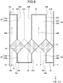
- FIG. 8 is a cross-sectional view of the casing 1 illustrated in FIG. 4 taken along line VIII-VIII.
- FIG. 9 is a first perspective view illustrating a configuration inside the casing 1 illustrated in FIG. 4 .
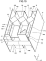
- FIG. 10 is a second perspective view illustrating the configuration inside the casing 1 illustrated in FIG. 4 .
- FIG. 9 illustrates the configuration inside the casing 1 as viewed at an angle from the plus Y direction side.
- FIG. 10 illustrates the configuration inside the casing 1 as viewed at an angle from the minus Y direction side.
- the line V-V illustrated in FIG. 4 represents a cross section between the upper face 1A and the partition 17.
- the line VI-VI illustrated in FIG. 4 represents a cross section between the partition 17 and the partitions 13 and 14.
- the line VII-VII illustrated in FIG. 4 represents a cross section between the partitions 13 and 14 and the partition 18.
- the line VIII-VIII illustrated in FIG. 4 represents a cross section between the partition 18 and the lower face 1B. Note that, in FIGS. 5 to 8 , part of the casing 1 illustrated in FIG. 4 on the minus Y direction side with respect to the partition 15 and part thereof on the plus Y direction side with respect to the partition 16 are not illustrated. In FIGS. 5 to 8 , the heat exchangers 4A, 4B, 4C, 5A, 5B, and 5C are dotted.
- a partition 41A separates two air passages 23A and 23B from each other.
- a partition 41B separates two air passages 23B and 23C from each other.
- a partition 41C separates two air passages 23C and 23D from each other. Ends of the partitions 41A, 41B, and 41C on the minus Y direction side are in contact with the partition 15. An end of the partition 41A on the plus Y direction side is in contact with a ridgeline of the heat exchanger 5A directed to the minus Y direction.
- An end of the partition 41B on the plus Y direction side is in contact with a ridgeline of the heat exchanger 5B directed to the minus Y direction.
- An end of the partition 41C on the plus Y direction side is in contact with a ridgeline of the heat exchanger 5C directed to the minus Y direction.
- Ends of the partitions 41A, 41B, and 41C on the plus Z direction side are in contact with the upper face 1A.
- Ends of the partitions 41A, 41B, and 41C on the minus Z direction side are in contact with the partition 17.
- a partition 42A separates two air passages 25A and 25B from each other.
- a partition 42B separates two air passages 25B and 25C from each other.
- a partition 42C separates two air passages 25C and 25D from each other. Ends of the partitions 42A, 42B, and 42C on the plus Y direction side are in contact with the partition 16. An end of the partition 42A on the minus Y direction side is in contact with a ridgeline of the heat exchanger 5A directed to the plus Y direction.
- An end of the partition 42B on the minus Y direction side is in contact with a ridgeline of the heat exchanger 5B directed to the plus Y direction.
- An end of the partition 42C on the minus Y direction side is in contact with a ridgeline of the heat exchanger 5C directed to the plus Y direction.
- Ends of the partitions 42A, 42B, and 42C on the plus Z direction side are in contact with the upper face 1A.
- Ends of the partitions 42A, 42B, and 42C on the minus Z direction side are in contact with the partition 18.
- a partition 43A separates two air passages 26A and 26B from each other.
- a partition 43B separates two air passages 26B and 26C from each other.
- a partition 43C separates two air passages 26C and 26D from each other. Ends of the partitions 43A, 43B, and 43C on the minus Y direction side are in contact with the partition 15. An end of the partition 43A on the plus Y direction side is in contact with a ridgeline of the heat exchanger 4A directed to the minus Y direction.
- An end of the partition 43B on the plus Y direction side is in contact with a ridgeline of the heat exchanger 4B directed to the minus Y direction.
- An end of the partition 43C on the plus Y direction side is in contact with a ridgeline of the heat exchanger 4C directed to the minus Y direction.
- Ends of the partitions 43A, 43B, and 43C on the plus Z direction side are in contact with the partition 17.
- Ends of the partitions 43A, 43B, and 43C on the minus Z direction side are in contact with the lower face 1B.
- the partitions 43A, 43B, and 43C stand on the lower face 1B in such a manner as to be capable of supporting the partition 17.
- a partition 50A separates two air passages 24A and 24B from each other.
- a partition 50B separates two air passages 24B and 24C from each other.
- a partition 50C separates two air passages 24C and 24D from each other. Ends of the partitions 50A, 50B, and 50C on the plus Y direction side are in contact with the partition 16. An end of the partition 50A on the minus Y direction side is in contact with a ridgeline of the heat exchanger 4A directed to the plus Y direction.
- An end of the partition 50B on the minus Y direction side is in contact with a ridgeline of the heat exchanger 4B directed to the plus Y direction.
- An end of the partition 50C on the minus Y direction side is in contact with a ridgeline of the heat exchanger 4C directed to the plus Y direction.
- Ends of the partitions 50A, 50B, and 50C on the plus Z direction side are in contact with the partition 18.
- Ends of the partitions 50A, 50B, and 50C on the minus Z direction side are in contact with the lower face 1B.
- the partitions 50A, 50B, and 50C stand on the lower face 1B in such a manner as to be capable of supporting the partition 18.
- two openings 44A and 44B are formed in the partition 15 on the plus Z direction side with respect to the partition 13.
- the opening 44A is formed between two partitions 41A and 41B on the plus Z direction side with respect to the partition 17 as illustrated in FIGS. 5 and 10 .
- the opening 44A is formed between two partitions 43A and 43B on the minus Z direction side with respect to the partition 17 as illustrated in FIGS. 6 and 10 .
- the opening 44B is formed between the partition 41C and the side face 1F on the plus Z direction side with respect to the partition 17 as illustrated in FIGS. 5 and 10 .
- the opening 44B is formed between the partition 43C and the side face 1F on the minus Z direction side with respect to the partition 17 as illustrated in FIGS. 6 and 10 .
- the air passage 23B is connected with the supply air passage 11A through the opening 44A.
- the air passage 23D is connected with the supply air passage 11A through the opening 44B. Ends of two air passages 23A and 23C on the minus Y direction side are blocked by the partition 15.
- the air passage 26B is connected with the supply air passage 11A through the opening 44A.
- the air passage 26D is connected with the supply air passage 11A through the opening 44B.
- ends of two air passages 26A and 26C on the minus Y direction side are blocked by the partition 15.
- two openings 48A and 48B are formed in the partition 15 on the minus Z direction side with respect to the partition 13.
- the opening 48A is formed between the side face 1E and the partition 43A.
- the opening 48B is formed between two partitions 43B and 43C.
- the air passage 26A is connected with the exhaust air passage 12B through the opening 48A.
- the air passage 26C is connected with the exhaust air passage 12B through the opening 48B.
- ends of two air passages 26B and 26D on the minus Y direction side are blocked by the partition 15.
- two openings 45A and 45B are formed in the partition 16 on the plus Z direction side with respect to the partition 14.
- the opening 45A is formed between the side face 1E and the partition 42A.
- the opening 45B is formed between two partitions 42B and 42C.
- the air passage 25A is connected with the supply air passage 11B through the opening 45A.
- the air passage 25C is connected with the supply air passage 11B through the opening 45B.
- ends of two air passages 25B and 25D on the plus Y direction side are blocked by the partition 16.
- two openings 49A and 49B are formed in the partition 16 on the minus Z direction side with respect to the partition 14.
- the opening 49A is formed between two partitions 42A and 42B on the plus Z direction side with respect to the partition 18 as illustrated in FIGS. 7 and 9 .
- the opening 49A is formed between two partitions 50A and 50B on the minus Z direction side with respect to the partition 18 as illustrated in FIGS. 8 and 9 .
- the opening 49B is formed between the partition 42C and the side face 1F on the plus Z direction side with respect to the partition 18 as illustrated in FIGS. 7 and 9 .
- the opening 49B is formed between the partition 50C and the side face 1F on the minus Z direction side with respect to the partition 18 as illustrated in FIGS. 8 and 9 .
- the air passage 25B is connected with the exhaust air passage 12A through the opening 49A.
- the air passage 25D is connected with the exhaust air passage 12A through the opening 49B.
- ends of two air passages 25A and 25C on the plus Y direction side are blocked by the partition 16.
- the air passage 24B is connected with the exhaust air passage 12A through the opening 49A.
- the air passage 24D is connected with the exhaust air passage 12A through the opening 49B. Ends of two air passages 24A and 24C on the plus Y direction side are blocked by the partition 16.
- the opening 46A is formed in a part of the partition 17 that separates the air passage 23A illustrated in FIG. 5 from the air passage 26A illustrated in FIG. 6 .
- the opening 46A is formed between a face of the heat exchanger 4A that exists between a ridgeline directed to the minus Y direction and a ridgeline directed to the minus X direction, and the side face 1E.
- the air passage 23A and the air passage 26A are connected with each other through the opening 46A.
- the opening 46B is formed in a part of the partition 17 that separates the air passage 23C illustrated in FIG. 5 from the air passage 26C illustrated in FIG. 6 .
- the opening 46B is formed between a face of the heat exchanger 4B that exists between a ridgeline directed to the minus Y direction and a ridgeline directed to the plus X direction, and a face of the heat exchanger 4C that exists between a ridgeline directed to the minus Y direction and a ridgeline directed to the minus X direction.
- the air passage 23C and the air passage 26C are connected with each other through the opening 46B.
- two openings 47A and 47B are formed in the partition 18.
- the opening 47A is formed in a part of the partition 18 that separates the air passage 25A illustrated in FIGS. 5 , 6 , and 7 from the air passage 24A illustrated in FIG. 8 .
- the opening 47A is formed between a face of the heat exchanger 5A that exists between a ridgeline directed to the plus Y direction and a ridgeline directed to the minus X direction, and the side face 1E.
- the air passage 25A and the air passage 24A are connected with each other through the opening 47A.
- the opening 47B is formed in a part of the partition 18 that separates the air passage 25C illustrated in FIGS. 5 , 6 , and 7 from the air passage 24C illustrated in FIG. 8 .
- the opening 47B is formed between a face of the heat exchanger 5B that exists between a ridgeline directed to the plus Y direction and a ridgeline directed to the plus X direction, and a face of the heat exchanger 5C that exists between a ridgeline directed to the plus Y direction and a ridgeline directed to the minus X direction.
- the air passage 25C and the air passage 24C are connected with each other through the opening 47B.
- FIG. 11 is a diagram explaining the movement of the exhaust air flow 21 in the casing 1 illustrated in FIG. 4 .
- FIG. 12 is a diagram explaining the movement of the supply air flow 22 in the casing 1 illustrated in FIG. 4 .
- the movement of the exhaust air flow 21 in the Y-axis direction and the Z-axis direction is expressed by alternate long and short dash line arrows.
- the movement of the supply air flow 22 in the Y-axis direction and the Z-axis direction is expressed by broken line arrows. Note that, in FIGS.
- the movement of the exhaust air flow 21 in the X-axis direction and the Y-axis direction is expressed by alternate long and short dash line arrows.
- the movement of the supply air flow 22 in the X-axis direction and the Y-axis direction is expressed by broken line arrows.
- a supply air flow 22A that has passed through the opening 44A on the plus Z direction side with respect to the partition 17 moves through the air passage 23B and flows into either one of two heat exchangers 5A and 5B.
- the supply air flow 22A that has passed through the opening 44B on the plus Z direction side with respect to the partition 17 moves through the air passage 23D and flows into the heat exchanger 5C.
- the supply air flow 22A that has passed through the secondary passages 32 of the heat exchanger 5A moves through the air passage 25A, and moves into the supply air passage 11B via the opening 45A.
- the supply air flow 22A that has passed through the secondary passages 32 of the heat exchanger 5B and the supply air flow 22A that has passed through the secondary passages 32 of the heat exchanger 5C move through the air passage 25C, and move into the supply air passage 11B via the opening 45B.
- Two air passages 23B and 23D are first supply air passages through which the supply air flow 22A caused to flow into the secondary passages 32 of the second heat exchangers 5 passes.
- the air passages 23B and 23D, which are the first supply air passages, are formed on the plus Z direction side of the first heat exchangers 4.
- a supply air flow 22B that has passed through the opening 44A on the minus Z direction side with respect to the partition 17 moves through the air passage 26B and flows into either one of two heat exchangers 4A and 4B.
- the supply air flow 22B that has passed through the opening 44B on the minus Z direction side with respect to the partition 17 moves through the air passage 26D and flows into the heat exchanger 4C.
- Two air passages 26B and 26D are third supply air passages through which the supply air flow 22B caused to flow into the secondary passages 32 of the first heat exchangers 4 passes.
- the supply air flow 22B that has passed through the secondary passages 32 of the heat exchanger 4A hits the partition 19, thus moves in the minus Z direction, and flows into the air passage 24A illustrated in FIG. 8 .
- the supply air flow 22B that has traveled through the air passage 24A flows into the air passage 25A via the opening 47A as illustrated in FIG. 6 .
- the supply air flow 22B that has moved through the air passage 25A moves into the supply air passage 11B via the opening 45A.
- the supply air flow 22B that has passed through the secondary passages 32 of the heat exchanger 4B and the supply air flow 22B that has passed through the secondary passages 32 of the heat exchanger 4C hit the partition 19, and flow into the air passage 24C illustrated in FIG. 8 .
- the supply air flow 22B that has moved through the air passage 24C flows into the air passage 25C via the opening 47B as illustrated in FIG. 6 .
- the supply air flow 22B that has moved through the air passage 25C moves into the supply air passage 11B via the opening 45B.
- Two air passages 24A and 24C are second supply air passages through which the supply air flow 22B flowing out of the secondary passages 32 of the first heat exchangers 4 passes.
- the air passages 24A and 24C, which are the second supply air passages are formed on the minus Z direction side of the second heat exchangers 5.
- Two air passages 25A and 25C are fourth supply air passages through which the supply air flow 22B flowing from the air passages 24A and 24C, which are the second supply air passages, passes.
- an exhaust air flow 21A that has passed through the opening 49A on the plus Z direction side with respect to the partition 18 moves through the air passage 25B and flows into either one of two heat exchangers 5A and 5B.
- the exhaust air flow 21A that has passed through the opening 49B on the plus Z direction side with respect to the partition 18 moves through the air passage 25D and flows into the heat exchanger 5C.
- Two air passages 25B and 25D are fourth exhaust air passages through which the exhaust air flow 21A caused to flow into the primary passages 31 of the second heat exchangers 5 passes.
- the air passages 25B and 25D, which are the fourth exhaust air passages, and the air passages 25A and 25C, which are the fourth supply air passages, are arranged in the X-axis direction.
- the exhaust air flow 21A that has moved through the primary passages 31 of the heat exchanger 5A hits the partition 19, thus moves in the plus Z direction, and flows into the air passage 23A illustrated in FIG. 5 .
- the exhaust air flow 21A that has moved through the air passage 23A flows into the air passage 26A via the opening 46A as illustrated in FIG. 7 .
- the exhaust air flow 21A that has moved through the air passage 26A moves into the exhaust air passage 12B via the opening 48A.
- the exhaust air flow 21A that has passed through the primary passages 31 of the heat exchanger 5B and the exhaust air flow 21A that has passed through the primary passages 31 of the heat exchanger 5C hit the partition 19 and flow into the air passage 23C illustrated in FIG. 5 .
- the exhaust air flow 21A that has moved through the air passage 23C flows into the air passage 26C via the opening 46B as illustrated in FIG. 7 .
- the exhaust air flow 21A that has moved through the air passage 26C moves into the exhaust air passage 12B via the opening 48B.
- Two air passages 23A and 23C are first exhaust air passages through which the exhaust air flow 21A flowing out of the primary passages 31 of the second heat exchangers 5 passes.
- the air passages 23A and 23C, which are the first exhaust air passages are formed on the plus Z direction side of the first heat exchangers 4.
- Two air passages 26A and 26C are third exhaust air passages through which the exhaust air flow 21A flowing from the air passages 23A and 23C, which are the first exhaust air passages, passes.
- the air passages 26A and 26C, which are the third exhaust air passages, and the air passages 26B and 26D, which are the third supply air passages, are arranged in the X-axis direction.
- an exhaust air flow 21B that has passed through the opening 49A on the minus Z direction side with respect to the partition 18 moves through the air passage 24B and flows into either one of two heat exchangers 4A and 4B.
- the exhaust air flow 21B that has passed through the opening 49B on the minus Z direction side with respect to the partition 18 moves through the air passage 24D and flows into the heat exchanger 4C.
- the exhaust air flow 21B that has passed through the primary passages 31 of the heat exchanger 4A moves through the air passage 26A, and moves into the exhaust air passage 12B via the opening 48A.
- the exhaust air flow 21B that has passed through the primary passages 31 of the heat exchanger 4B and the exhaust air flow 21B that has passed through the primary passages 31 of the heat exchanger 4C move through the air passage 26C, and moves into the exhaust air passage 12B via the opening 48B.
- Two air passages 24B and 24D are second exhaust air passages through which the exhaust air flow 21B caused to flow into the primary passages 31 of the first heat exchangers 4 passes.
- the air passages 24B and 24D, which are the second exhaust air passages, are formed on the minus Z direction side of the second heat exchangers 5.
- the heat exchangers 4A, 4B, and 4C exchange heat with the supply air flow 22B illustrated in FIG. 6 and the exhaust air flow 21B illustrated in FIG. 8 .
- the heat exchangers 5A, 5B, and 5C exchange heat with the supply air flow 22A illustrated in FIG. 5 and the exhaust air flow 21A illustrated in FIG. 7 .
- the partition 17, which is the first partition is provided between the air passages 23A, 23C, 23B, and 23D, which correspond to the first exhaust air passages and the first supply air passages, and the air passages 26A, 26C, 26B, and 26D, which correspond to the third exhaust air passages and the third supply air passages.
- the partition 18, which is the second partition is provided between the air passages 24B, 24D, 24A, and 24C, which correspond to the second exhaust air passages and the second supply air passages, and the air passages 25B, 25D, 25A, and 25C, which correspond to the fourth exhaust air passages and the fourth supply air passages.
- provision of the partitions 17 and 18 enables the air passages for the exhaust air flow 21 and the air passages for the supply air flow 22 to be separated from each other.
- the partition 19, which is the third partition, is provided between the first heat exchangers 4 and the second heat exchangers 5 within the range between the partition 17 and the partition 18 in the Z-axis direction.
- provision of the partition 19 enables the supply air flow 22 having passed through the secondary passages 32 of the first heat exchangers 4 to be guided to the air passages 24A and 24C, which are the second supply air passages, and the exhaust air flow 21 having passed through the primary passages 31 of the second heat exchangers 5 to be guided to the air passages 23A and 23C, which are the first exhaust air passages.
- the third supply air passages and the third exhaust air passages are arranged in the Z-axis direction, the third supply air passages and the third exhaust air passages can be separated from the first supply air passages and the first exhaust air passages by one partition 17, which achieves a simple structure.
- the fourth supply air passages and the fourth exhaust air passages are arranged in the Z-axis direction, the fourth supply air passages and the fourth exhaust air passages can be separated from the second supply air passages and the second exhaust air passages by one partition 18, which achieves a simple structure.
- provision of the partitions 41A, 41B, and 41C enables separation of the air passages 23A and 23C, which are the first exhaust air passages, from the air passages 23B and 23D, which are the first supply air passages.
- provision of the partitions 50A, 50B, and 50C enables separation of the air passages 24B and 24D, which are the second exhaust air passages, from the air passages 24A and 24C, which are the second supply air passages.
- provision of the partitions 43A, 43B, and 43C enables separation of the air passages 26A and 26C, which are the third exhaust air passages, from the air passages 26B and 26D, which are the third supply air passages.
- provision of the partitions 42A, 42B, and 42C enables separation of the air passages 25B and 25D, which are the fourth exhaust air passages, from the air passages 25A and 25C, which are the fourth supply air passages.
- the partitions 43A, 43B, and 43C may be omitted, and the ridgelines directed to the minus Y direction of the heat exchangers 4A, 4B, and 4C may be in contact with the partition 15.
- the air passages 26A and 26C which are the third exhaust air passages
- the air passages 26B and 26D which are the third supply air passages
- the partitions 42A, 42B, and 42C may be omitted, and the ridgelines directed to the plus Y direction of the heat exchangers 5A, 5B, and 5C may be in contact with the partition 16.
- the air passages 25B and 25D which are the fourth exhaust air passages
- the air passages 25A and 25C which are the fourth supply air passages
- the first heat exchangers 4 extend further on the minus Z direction side than the second heat exchangers 5, which enables the air passages 23B and 23D for guiding the supply air flow 22A to the second heat exchangers 5 to be provided on the plus Z direction side of the first heat exchangers 4.
- the air passages 23A and 23C for guiding the exhaust air flow 21A flowing out from the second heat exchangers 5 to the exhaust air passage 12B can be provided on the plus Z direction side of the first heat exchangers 4.
- the second heat exchangers 5 extend further on the plus Z direction side than the first heat exchangers 4, which enables the air passages 24B and 24D for guiding the exhaust air flow 21B to the first heat exchangers 4 to be provided on the minus Z direction side of the second heat exchangers 5.
- the air passages 24A and 24C for guiding the supply air flow 22B flowing out from the first heat exchangers 4 to the supply air passage 11B can be provided on the minus Z direction side of the second heat exchangers 5.
- the number of the first heat exchangers 4 arranged in the X-axis direction and the number of second heat exchangers 5 arranged in the X-axis direction are not limited to three, and may be one or two, or may be larger than three.
- the number of first heat exchangers 4 and the number of second heat exchangers 5 are appropriately determined on the basis of the size of the ventilator 100 or the performance required of the ventilator 100.
- the first side on which the first heat exchangers 4 extend further than the second heat exchangers 5 may be the plus Z direction side instead of the minus Z direction side.
- the second side on which the second heat exchangers 5 extend further than the first heat exchangers 4 may be the minus Z direction side instead of the plus Z direction side.
- the first heat exchangers 4 and the second heat exchangers 5 only need to extend further than each other on the sides opposite to each other in the Z-axis direction.
- the air passages in the ventilator 100 are not limited to those arranged so that the supply air flow 22 sucked into an upper space in the casing 1 is forced out from the upper space in the casing 1 and that the exhaust air flow 21 sucked into a lower space in the casing 1 is forced out from the lower space in the casing 1.
- the arrangement of the air passages may be changed so that the supply air flow 22 sucked into a lower space in the casing 1 is forced out from the lower space in the casing 1 and that the exhaust air flow 21 sucked into an upper space in the casing 1 is forced out from the upper space in the casing 1.
- the arrangement of the air passages may be changed so that the supply air flow 22 sucked into an upper space in the casing 1 is forced out from a lower space in the casing 1 and that the exhaust air flow 21 sucked into the upper space in the casing 1 is forced out from the lower space in the casing 1.
- the arrangement of the air passages may be changed so that the supply air flow 22 sucked into a lower space in the casing 1 is forced out from an upper space in the casing 1 and that the exhaust air flow 21 sucked into the lower space in the casing 1 is forced out from the upper space in the casing 1.
- the first heat exchangers 4 and the second heat exchangers 5 are arranged in the Y-axis direction.
- the first heat exchangers 4 extend further on the first side than the second heat exchangers 5, and the second heat exchangers 5 extend further on the second side than the first heat exchangers 4.
- the ventilator 100 produces effect of reducing the pressure loss while accommodating the heat exchangers within a size required of the heat exchange ventilator.
Landscapes
- Engineering & Computer Science (AREA)
- Chemical & Material Sciences (AREA)
- Combustion & Propulsion (AREA)
- Mechanical Engineering (AREA)
- General Engineering & Computer Science (AREA)
- Heat-Exchange Devices With Radiators And Conduit Assemblies (AREA)
- Central Air Conditioning (AREA)
Abstract
Description
- The present invention relates to a heat exchange ventilator that performs ventilation while carrying out heat exchange with a supply air flow and an exhaust air flow.
- Heat exchange ventilators each including a plurality of heat exchangers have been known. In some cases, heat exchangers are arranged in series so that air having flown through one heat exchanger flows into another heat exchanger, and in other cases, heat exchangers are arranged in parallel so that air is divided and flows separately into one heat exchanger and another heat exchanger.
Patent Literature 1 teaches a heat exchange ventilator including two heat exchangers arranged in parallel. - Patent Literature 1: Japanese Patent No.
4391099 - In a heat exchange ventilator, the pressure loss can be reduced by increasing the height of heat exchangers in the stacking direction of layers through which air flows pass. In a case where a plurality of heat exchangers are arranged in parallel as described in
Patent Literature 1 mentioned above, however, the height of the heat exchangers may be limited so that the heat exchangers can be accommodated within a size required of a heat exchange ventilator. Thus, in related art, there is a problem in that it is difficult to reduce the pressure loss while accommodating heat exchangers within a size required of a heat exchange ventilator. - The present invention has been made in view of the above, and an object thereof is to provide a heat exchange ventilator capable of reducing the pressure loss while accommodating heat exchangers within a size required of a heat exchange ventilator.
- To solve the aforementioned problems and achieve the object, a heat exchange ventilator according to the present invention includes an exhaust fan that generates an exhaust air flow flowing from the inside to the outside of a room, a supply fan that generates a supply air flow flowing from the outside to the inside of the room, and a first heat exchanger and a second heat exchanger each of which includes primary passages through which the exhaust air flow passes and secondary passages through which the supply air flow passes, and carries out heat exchange between the exhaust air flow and the supply air flow. The first heat exchanger and the second heat exchanger are arranged in a second direction perpendicular to a first direction in which members forming the primary passages and members forming the secondary passages are stacked. The first heat exchanger extends further on a first side in the first direction than the second heat exchanger. The second heat exchanger extends further on a second side opposite to the first side in the first direction than the first heat exchanger.
- The heat exchange ventilator according to the present invention produces an effect of reducing the pressure loss while accommodating the heat exchangers within a size required of the heat exchange ventilator.
-
-
FIG. 1 is a diagram illustrating a configuration of a heat exchange ventilator according to a first embodiment of the present invention. -
FIG. 2 is a diagram illustrating first heat exchangers and second heat exchangers illustrated inFIG. 1 . -
FIG. 3 is a perspective view of a first heat exchanger illustrated inFIG. 2 . -
FIG. 4 is a diagram explaining the arrangement of air passages in a casing of the heat exchange ventilator illustrated inFIG. 1 . -
FIG. 5 is a cross-sectional view of the casing illustrated inFIG. 4 taken along line V-V. -
FIG. 6 is a cross-sectional view of the casing illustrated inFIG. 4 taken along line VI-VI. -
FIG. 7 is a cross-sectional view of the casing illustrated inFIG. 4 taken along line VII-VII. -
FIG. 8 is a cross-sectional view of the casing illustrated inFIG. 4 taken along line VIII-VIII. -
FIG. 9 is a first perspective view illustrating a configuration inside the casing illustrated inFIG. 4 . -
FIG. 10 is a second perspective view illustrating the configuration inside the casing illustrated inFIG. 4 . -
FIG. 11 is a diagram explaining movement of an exhaust air flow in the casing illustrated inFIG. 4 . -
FIG. 12 is a diagram explaining movement of a supply air flow in the casing illustrated inFIG. 4 . - A heat exchange ventilator according to an embodiment of the present invention will be described in detail below with reference to the drawings. Note that the present invention is not limited to the embodiment.
-
FIG. 1 is a diagram illustrating a configuration of a heat exchange ventilator according to a first embodiment of the present invention. Aventilator 100, which is a heat exchange ventilator, performs ventilation while carrying out heat exchange between anexhaust air flow 21 and asupply air flow 22. Theexhaust air flow 21 is a flow of air exhausted from the inside to the outside of a room via theventilator 100. Thesupply air flow 22 is a flow of air supplied from the outside to the inside of the room via theventilator 100. Theventilator 100 ventilates the room by exhausting air from the inside to the outside of the room and supplying air from the outside to the inside of the room to maintain comfortable air environment in the room. In addition, theventilator 100 reduces the difference in temperature and the difference in humidity between air taken into the room and air inside the room by heat exchange between theexhaust air flow 21 and thesupply air flow 22, to reduce the load of room air conditioning. - In the first embodiment, the
ventilator 100 is an air handling unit (AHU) capable of supplying and exhausting air in large volumes. Theventilator 100 is installed on the floor in the room. Theventilator 100 may be installed on the ceiling of a room, or may be installed outdoors such as on the roof of a building. - In the first embodiment, an X axis, a Y axis, and a Z axis are three axes perpendicular to each other. The Z axis is a vertical axis. A Z-axis direction, which is a first direction, is a direction parallel to the Z axis. A Y-axis direction, which is a second direction, is a direction parallel to the Y axis. An X-axis direction, which is a third direction, is a direction parallel to the X axis. In the drawings, the direction indicated by an arrow along the Z-axis direction will be referred to as a plus Z direction, and the direction opposite to the arrow will be referred to as a minus Z direction. The plus Z direction is a vertically upward direction. The minus Z direction is a vertically downward direction. The direction indicated by an arrow along the Y-axis direction will be referred to as a plus Y direction, and the direction opposite to the arrow will be referred to as a minus Y direction. The direction indicated by an arrow along the X-axis direction will be referred to as a plus X direction, and the direction opposite to the arrow will be referred to as a minus X direction.
- The
ventilator 100 includes anexhaust fan 2 for generating an exhaust air flow that flows from the inside to the outside of the room, and asupply fan 3 for generating a supply air flow that flows from the outside to the inside of the room. Theexhaust fan 2 takes in air from the inside of the room, and sends the taken-in air to the outside. Thesupply fan 3 draws air from the outside of the room, and sends the drawn air to the inside. - The
ventilator 100 includesfirst heat exchangers 4 andsecond heat exchangers 5 that carry out heat exchange between theexhaust air flow 21 and thesupply air flow 22. Theexhaust fan 2, thesupply fan 3, thefirst heat exchangers 4, and thesecond heat exchangers 5 are accommodated in acasing 1. Thecasing 1 is a box having six faces, which are anupper face 1A and alower face 1B, and four side faces 1C, 1D, 1E, and 1F. InFIG. 1 , four of the six faces, which are theupper face 1A, thelower face 1B, and two side faces 1C and 1D are illustrated. Theside face 1E is located deeper than the sheet surface ofFIG. 1 . Theside face 1F is located nearer to the viewer than the sheet surface ofFIG. 1. FIG. 1 schematically illustrates components provided inside thecasing 1. In thecasing 1, an air passage through which theexhaust air flow 21 passes, and an air passage through which thesupply air flow 22 passes are formed. - A supply
air inlet port 6 and an exhaustair outlet port 7 are provided on the side face 1C on the minus Y direction side of thecasing 1. A supplyair outlet port 8 and an exhaustair inlet port 9 are provided on theside face 1D on the plus Y direction side of thecasing 1. Thesupply air flow 22 sucked into the supplyair inlet port 6 flows inside thecasing 1 in the plus Y direction, and is forced out through the supplyair outlet port 8. Theexhaust air flow 21 sucked into the exhaustair inlet port 9 flows inside thecasing 1 in the minus Y direction, and is forced out through the exhaustair outlet port 7. - The
ventilator 100 draws air from the outside of the room into asupply air passage 11A through the supplyair inlet port 6. The air drawn into thesupply air passage 11A passes through asupply air passage 11B, and is forced out into the room through the supplyair outlet port 8. In addition, theventilator 100 draws air from the inside of the room into anexhaust air passage 12A through the exhaustair inlet port 9. The air drawn into theexhaust air passage 12A passes through theexhaust air passage 12B, and is forced out of the room through the exhaustair outlet port 7. - The
supply air passages upper face 1A side in thecasing 1. Theexhaust air passages lower face 1B side in thecasing 1. Apartition 13 separates thesupply air passage 11A from theexhaust air passage 12B. Apartition 14 separates thesupply air passage 11B from theexhaust air passage 12A. - The
first heat exchangers 4 and thesecond heat exchangers 5 are arranged along the Y-axis direction. Thefirst heat exchangers 4 extend further on the minus Z direction side, which is a first side, than thesecond heat exchangers 5 in the Z-axis direction. Thesecond heat exchangers 5 extend further on the plus Z direction side, which is a second side opposite to the first side, than thefirst heat exchangers 4 in the Z-axis direction. A part of thefirst heat exchangers 4 other than the part extending further on the minus Z direction side than thesecond heat exchangers 5 and a part of thesecond heat exchangers 5 other than the part extending further on the plus Z direction side than thefirst heat exchangers 4, are positioned within the same range of height in the Z-axis direction. - A
partition 15 is provided on the plus Y direction side of thesupply air passage 11A and theexhaust air passage 12B. Thepartition 15 separates a space including thesupply air passage 11A and theexhaust air passage 12B from a space including thefirst heat exchangers 4 and thesecond heat exchangers 5. Thepartition 15 has an opening through which theexhaust air flow 21 passes, and an opening through which thesupply air flow 22 passes. - A
partition 16 is provided on the minus Y direction side of thesupply air passage 11B and theexhaust air passage 12A. Thepartition 16 separates a space including thesupply air passage 11B and theexhaust air passage 12A from the space including thefirst heat exchangers 4 and thesecond heat exchangers 5. Thepartition 16 has an opening through which theexhaust air flow 21 passes, and an opening through which thesupply air flow 22 passes. The space inside thecasing 1 is separated by the twopartitions supply air passage 11A and theexhaust air passage 12B, the space including thefirst heat exchangers 4 and thesecond heat exchangers 5, and the space of thesupply air passage 11B and theexhaust air passage 12A. These three spaces are arranged in a row in the Y-axis direction. - A
partition 17, which is a first partition, is provided on the plus Z direction side of thefirst heat exchangers 4. An end of thepartition 17 on the minus Y direction side is in contact with thepartition 15. Thefirst heat exchangers 4 are located in a space between thepartition 17 and thelower face 1B. Apartition 18, which is a second partition, is provided on the minus Z direction side of thesecond heat exchangers 5. An end of thepartition 18 on the plus Y direction side is in contact with thepartition 16. Thesecond heat exchangers 5 are located in a space between thepartition 18 and theupper face 1A. - A
partition 19, which is a third partition, is provided between thefirst heat exchangers 4 and thesecond heat exchangers 5. Thepartition 19 separates a space in which thefirst heat exchangers 4 are provided from a space in which thesecond heat exchangers 5 are provided within the range of height between thepartition 17 and thepartition 18 in the Z-axis direction. An end of thepartition 19 on the plus Z direction side is in contact with an end of thepartition 17 on the plus Y direction side. An end of thepartition 19 on the minus Z direction side is in contact with an end of thepartition 18 on the minus Y direction side. -
FIG. 2 is a diagram illustrating thefirst heat exchangers 4 and thesecond heat exchangers 5 illustrated inFIG. 1 . Theventilator 100 includes threeheat exchangers first heat exchangers 4, and threeheat exchangers heat exchanger - The
heat exchangers heat exchangers heat exchangers heat exchangers - Because the six
heat exchangers ventilator 100, theventilator 100 is reduced in size in the X-axis direction as compared with a case where the sixheat exchangers second heat exchangers 5 is arranged on the plus Y direction side of the row of thefirst heat exchangers 4 in theventilator 100, theventilator 100 is reduced in size in the Z-axis direction as compared with a case where the row of thesecond heat exchangers 5 is arranged on the plus Z direction side of the row of thefirst heat exchangers 4. -
FIG. 3 is a perspective view of afirst heat exchanger 4 illustrated inFIG. 2 .FIG. 3 illustrates theheat exchanger 4A, which is one of thefirst heat exchangers 4. Theheat exchanger 4A is a crossflow total heat exchange element in which the moving direction of theexhaust air flow 21 and the moving direction of thesupply air flow 22 passing through theheat exchanger 4A are perpendicular to each other. Note that the Y-axis direction and the Z-axis direction are indicated by the same arrow inFIG. 3 . Theheat exchangers FIG. 2 has configurations similar to that of theheat exchanger 4A. - The
heat exchanger 4A includes a plurality ofsheet materials 33 arranged with spaces therebetween, andspacer members 34 that keep the spaces between thesheet materials 33. Theheat exchanger 4A is a stacked structure of thesheet materials 33 and thespacer members 34. Thesheet materials 33 are plates machined to be flat. Thespacer members 34 are corrugated sheet members. Thesheet materials 33 and thespacer members 34 are bonded to each other. - The
spacer members 34 includespacer members 34A andspacer members 34B that differ from each other in orientation so that the directions of folds of thespacer members 34A and thespacer members 34B are perpendicular to each other. Spaces formed between thespacer members 34B and thesheet materials 33 areprimary passages 31 through which theexhaust air flow 21 passes. Spaces formed between thespacer members 34A and thesheet materials 33 aresecondary passages 32 through which thesupply air flow 22 passes. A plurality ofprimary passages 31 and a plurality ofsecondary passages 32 are formed in theheat exchanger 4A. Thesheet materials 33, thespacer members 34B, which are members constituting theprimary passages 31, and thespacer members 34A, which are members constituting thesecondary passages 32, are stacked in the Z-axis direction. At thesheet materials 33, sensible heat exchange and latent heat exchange between theexhaust air flow 21 passing through theprimary passages 31 and thesupply air flow 22 passing through thesecondary passages 32 are carried out without causing mixture of theexhaust air flow 21 and thesupply air flow 22. - As the volumes of supply air and exhaust air in a heat exchange ventilator increase, the pressure loss may increase in heat exchangers owing to an increase in ventilation resistance. The pressure loss in a heat exchanger can be reduced by increasing the size of the heat exchanger in the stacking direction of layers through which air flows pass.
- In the first embodiment, part of the
first heat exchangers 4 and part of thesecond heat exchangers 5 are positioned within the same range of height in the Z-axis direction. This enables thefirst heat exchangers 4 and thesecond heat exchangers 5 to be more compactly accommodated in theventilator 100 than a case where thefirst heat exchangers 4 and thesecond heat exchangers 5 are simply arranged in parallel in the Z-axis direction. - In addition, the
ventilator 100 increases less in the size of the structure when the size of thefirst heat exchangers 4 in the Z-axis direction and the size of thesecond heat exchangers 5 in the Z-axis direction are increased as compared with the case where thefirst heat exchangers 4 and thesecond heat exchangers 5 are simply arranged in parallel in the Z-axis direction. The increase in the sizes in the Z-axis direction, which is the stacking direction of the layers through which air flows passes, reduces the ventilation resistance in thefirst heat exchangers 4 and thesecond heat exchangers 5. In theventilator 100, the reduction in the ventilation resistance reduces the pressure loss in thefirst heat exchangers 4 and thesecond heat exchangers 5. Because the pressure loss increases as the volumes of supply air and exhaust air increase, the arrangement of thefirst heat exchangers 4 and thesecond heat exchangers 5 in the first embodiment is suitable for aventilator 100 that supplies and exhaust air in large volumes. In theventilator 100, the pressure loss can also be reduced by arranging thefirst heat exchangers 4 and thesecond heat exchangers 5, which correspond to a plurality of heat exchangers, in parallel as compared with a case where only one heat exchanger is provided. This enables theventilator 100 to reduce the pressure loss while accommodating thefirst heat exchangers 4 and thesecond heat exchanger 5 within a limited size. - Next, arrangement of air passages in the
ventilator 100 will be explained.FIG. 4 is a diagram explaining the arrangement of air passages in thecasing 1 of the heat exchange ventilator illustrated inFIG. 1 .FIG. 4 illustrates the inside of thecasing 1 in a state in which theside face 1F is removed. Thecasing 1 and thepartitions FIG. 4 , theheat exchanger 4C, which is located at the outermost position on the plus X direction side among theheat exchangers heat exchanger 5C, which is located at the outermost position on the plus X direction side among theheat exchangers FIG. 4 , theexhaust fan 2 and thesupply fan 3 are not illustrated. - A space between the
partition 17 and theupper face 1A is divided into a plurality ofair passages 23 arranged in parallel in the X-axis direction. InFIG. 4 , one of theair passages 23, which is located at the outermost position on the plus X direction side, is illustrated. Theair passages 23 are formed between thepartition 15 and theheat exchangers - A space between the
partition 18 and thelower face 1B is divided into a plurality ofair passages 24 arranged in parallel in the X-axis direction. InFIG. 4 , one of theair passages 24, which is located at the outermost position on the plus X direction side, is illustrated. Theair passages 24 are formed between thepartition 16 and theheat exchangers - The space between the
partition 18 and theupper face 1A is divided into a plurality ofair passages 25 arranged in parallel in the X-axis direction. InFIG. 4 , one of theair passages 25, which is located at the outermost position on the plus X direction side, is illustrated. Theair passages 25 are formed between thepartition 16 and theheat exchangers - The space between the
partition 17 and thelower face 1B is divided into a plurality ofair passages 26 arranged in parallel in the X-axis direction. InFIG. 4 , one of theair passages 26, which is located at the outermost position on the plus X direction side, is illustrated. Theair passages 26 are formed between thepartition 15 and theheat exchangers -
FIG. 5 is a cross-sectional view of thecasing 1 illustrated inFIG. 4 taken along line V-V.FIG. 6 is a cross-sectional view of thecasing 1 illustrated inFIG. 4 taken along line VI-VI.FIG. 7 is a cross-sectional view of thecasing 1 illustrated inFIG. 4 taken along line VII-VII.FIG. 8 is a cross-sectional view of thecasing 1 illustrated inFIG. 4 taken along line VIII-VIII.FIG. 9 is a first perspective view illustrating a configuration inside thecasing 1 illustrated inFIG. 4 .FIG. 10 is a second perspective view illustrating the configuration inside thecasing 1 illustrated inFIG. 4 .FIG. 9 illustrates the configuration inside thecasing 1 as viewed at an angle from the plus Y direction side.FIG. 10 illustrates the configuration inside thecasing 1 as viewed at an angle from the minus Y direction side. - The line V-V illustrated in
FIG. 4 represents a cross section between theupper face 1A and thepartition 17. The line VI-VI illustrated inFIG. 4 represents a cross section between thepartition 17 and thepartitions FIG. 4 represents a cross section between thepartitions partition 18. The line VIII-VIII illustrated inFIG. 4 represents a cross section between thepartition 18 and thelower face 1B. Note that, inFIGS. 5 to 8 , part of thecasing 1 illustrated inFIG. 4 on the minus Y direction side with respect to thepartition 15 and part thereof on the plus Y direction side with respect to thepartition 16 are not illustrated. InFIGS. 5 to 8 , theheat exchangers - As illustrated in
FIG. 5 , fourair passages air passages 23, are formed between the side face 1E and theside face 1F. Apartition 41A separates twoair passages partition 41B separates twoair passages partition 41C separates twoair passages partitions partition 15. An end of thepartition 41A on the plus Y direction side is in contact with a ridgeline of theheat exchanger 5A directed to the minus Y direction. An end of thepartition 41B on the plus Y direction side is in contact with a ridgeline of theheat exchanger 5B directed to the minus Y direction. An end of thepartition 41C on the plus Y direction side is in contact with a ridgeline of theheat exchanger 5C directed to the minus Y direction. Ends of thepartitions upper face 1A. Ends of thepartitions partition 17. - As illustrated in
FIGS. 5 ,6 , and7 , fourair passages air passages 25, are formed between the side face 1E and theside face 1F. Apartition 42A separates twoair passages partition 42B separates twoair passages partition 42C separates twoair passages partitions partition 16. An end of thepartition 42A on the minus Y direction side is in contact with a ridgeline of theheat exchanger 5A directed to the plus Y direction. An end of thepartition 42B on the minus Y direction side is in contact with a ridgeline of theheat exchanger 5B directed to the plus Y direction. An end of thepartition 42C on the minus Y direction side is in contact with a ridgeline of theheat exchanger 5C directed to the plus Y direction. Ends of thepartitions upper face 1A. Ends of thepartitions partition 18. - As illustrated in
FIGS. 6 ,7 , and8 , fourair passages air passages 26, are formed between the side face 1E and theside face 1F. Apartition 43A separates twoair passages partition 43B separates twoair passages partition 43C separates twoair passages partitions partition 15. An end of thepartition 43A on the plus Y direction side is in contact with a ridgeline of theheat exchanger 4A directed to the minus Y direction. An end of thepartition 43B on the plus Y direction side is in contact with a ridgeline of theheat exchanger 4B directed to the minus Y direction. An end of thepartition 43C on the plus Y direction side is in contact with a ridgeline of theheat exchanger 4C directed to the minus Y direction. Ends of thepartitions partition 17. Ends of thepartitions lower face 1B. Thepartitions lower face 1B in such a manner as to be capable of supporting thepartition 17. - As illustrated in
FIG. 8 , fourair passages air passages 24, are formed between the side face 1E and theside face 1F. Apartition 50A separates twoair passages partition 50B separates twoair passages partition 50C separates twoair passages partitions partition 16. An end of thepartition 50A on the minus Y direction side is in contact with a ridgeline of theheat exchanger 4A directed to the plus Y direction. An end of thepartition 50B on the minus Y direction side is in contact with a ridgeline of theheat exchanger 4B directed to the plus Y direction. An end of thepartition 50C on the minus Y direction side is in contact with a ridgeline of theheat exchanger 4C directed to the plus Y direction. Ends of thepartitions partition 18. Ends of thepartitions lower face 1B. Thepartitions lower face 1B in such a manner as to be capable of supporting thepartition 18. - As illustrated in
FIGS. 5 ,6 , and10 , twoopenings partition 15 on the plus Z direction side with respect to thepartition 13. Theopening 44A is formed between twopartitions partition 17 as illustrated inFIGS. 5 and10 . Theopening 44A is formed between twopartitions partition 17 as illustrated inFIGS. 6 and10 . Theopening 44B is formed between thepartition 41C and theside face 1F on the plus Z direction side with respect to thepartition 17 as illustrated inFIGS. 5 and10 . Theopening 44B is formed between thepartition 43C and theside face 1F on the minus Z direction side with respect to thepartition 17 as illustrated inFIGS. 6 and10 . - As illustrated in
FIG. 5 , theair passage 23B is connected with thesupply air passage 11A through theopening 44A. Theair passage 23D is connected with thesupply air passage 11A through theopening 44B. Ends of twoair passages partition 15. - As illustrated in
FIG. 6 , on the plus Z direction side with respect to thepartition 13, theair passage 26B is connected with thesupply air passage 11A through theopening 44A. On the plus Z direction side with respect to thepartition 13, theair passage 26D is connected with thesupply air passage 11A through theopening 44B. On the plus Z direction side with respect to thepartition 13, ends of twoair passages partition 15. - As illustrated in
FIGS. 7 ,8 , and10 , twoopenings partition 15 on the minus Z direction side with respect to thepartition 13. Theopening 48A is formed between the side face 1E and thepartition 43A. Theopening 48B is formed between twopartitions - As illustrated in
FIGS. 7 and8 , on the minus Z direction side with respect to thepartition 13, theair passage 26A is connected with theexhaust air passage 12B through theopening 48A. On the minus Z direction side with respect to thepartition 13, theair passage 26C is connected with theexhaust air passage 12B through theopening 48B. On the minus Z direction side with respect to thepartition 13, ends of twoair passages partition 15. - As illustrated in
FIGS. 5 ,6 , and9 , twoopenings partition 16 on the plus Z direction side with respect to thepartition 14. Theopening 45A is formed between the side face 1E and thepartition 42A. Theopening 45B is formed between twopartitions - As illustrated in
FIGS. 5 and6 , on the plus Z direction side with respect to thepartition 14, theair passage 25A is connected with thesupply air passage 11B through theopening 45A. On the plus Z direction side with respect to thepartition 14, theair passage 25C is connected with thesupply air passage 11B through theopening 45B. On the plus Z direction side with respect to thepartition 14, ends of twoair passages partition 16. - As illustrated in
FIGS. 7 ,8 , and9 , twoopenings partition 16 on the minus Z direction side with respect to thepartition 14. Theopening 49A is formed between twopartitions partition 18 as illustrated inFIGS. 7 and9 . Theopening 49A is formed between twopartitions partition 18 as illustrated inFIGS. 8 and9 . Theopening 49B is formed between thepartition 42C and theside face 1F on the plus Z direction side with respect to thepartition 18 as illustrated inFIGS. 7 and9 . Theopening 49B is formed between thepartition 50C and theside face 1F on the minus Z direction side with respect to thepartition 18 as illustrated inFIGS. 8 and9 . - As illustrated in
FIG. 7 , on the minus Z direction side with respect to thepartition 14, theair passage 25B is connected with theexhaust air passage 12A through theopening 49A. On the minus Z direction side with respect to thepartition 14, theair passage 25D is connected with theexhaust air passage 12A through theopening 49B. On the minus Z direction side with respect to thepartition 14, ends of twoair passages partition 16. - As illustrated in
FIG. 8 , theair passage 24B is connected with theexhaust air passage 12A through theopening 49A. Theair passage 24D is connected with theexhaust air passage 12A through theopening 49B. Ends of twoair passages partition 16. - As illustrated in
FIGS. 5 and10 , twoopenings partition 17. Theopening 46A is formed in a part of thepartition 17 that separates theair passage 23A illustrated inFIG. 5 from theair passage 26A illustrated inFIG. 6 . Theopening 46A is formed between a face of theheat exchanger 4A that exists between a ridgeline directed to the minus Y direction and a ridgeline directed to the minus X direction, and theside face 1E. Theair passage 23A and theair passage 26A are connected with each other through theopening 46A. - The
opening 46B is formed in a part of thepartition 17 that separates theair passage 23C illustrated inFIG. 5 from theair passage 26C illustrated inFIG. 6 . Theopening 46B is formed between a face of theheat exchanger 4B that exists between a ridgeline directed to the minus Y direction and a ridgeline directed to the plus X direction, and a face of theheat exchanger 4C that exists between a ridgeline directed to the minus Y direction and a ridgeline directed to the minus X direction. Theair passage 23C and theair passage 26C are connected with each other through theopening 46B. - As illustrated in
FIGS. 5 ,6 , and7 , twoopenings partition 18. Theopening 47A is formed in a part of thepartition 18 that separates theair passage 25A illustrated inFIGS. 5 ,6 , and7 from theair passage 24A illustrated inFIG. 8 . Theopening 47A is formed between a face of theheat exchanger 5A that exists between a ridgeline directed to the plus Y direction and a ridgeline directed to the minus X direction, and theside face 1E. Theair passage 25A and theair passage 24A are connected with each other through theopening 47A. - The
opening 47B is formed in a part of thepartition 18 that separates theair passage 25C illustrated inFIGS. 5 ,6 , and7 from theair passage 24C illustrated inFIG. 8 . Theopening 47B is formed between a face of theheat exchanger 5B that exists between a ridgeline directed to the plus Y direction and a ridgeline directed to the plus X direction, and a face of theheat exchanger 5C that exists between a ridgeline directed to the plus Y direction and a ridgeline directed to the minus X direction. Theair passage 25C and theair passage 24C are connected with each other through theopening 47B. - Next, the movements of the
exhaust air flow 21 and thesupply air flow 22 in theventilator 100 will be explained with reference toFIGS. 5 to 8 ,11, and 12. FIG. 11 is a diagram explaining the movement of theexhaust air flow 21 in thecasing 1 illustrated inFIG. 4 .FIG. 12 is a diagram explaining the movement of thesupply air flow 22 in thecasing 1 illustrated inFIG. 4 . InFIG. 11 , the movement of theexhaust air flow 21 in the Y-axis direction and the Z-axis direction is expressed by alternate long and short dash line arrows. InFIG. 12 , the movement of thesupply air flow 22 in the Y-axis direction and the Z-axis direction is expressed by broken line arrows. Note that, inFIGS. 5 to 8 , the movement of theexhaust air flow 21 in the X-axis direction and the Y-axis direction is expressed by alternate long and short dash line arrows. InFIGS. 5 to 8 , the movement of thesupply air flow 22 in the X-axis direction and the Y-axis direction is expressed by broken line arrows. - Of the
supply air flow 22 that has moved from the supplyair inlet port 6 to thesupply air passage 11A illustrated inFIG. 4 , asupply air flow 22A that has passed through theopening 44A on the plus Z direction side with respect to thepartition 17 moves through theair passage 23B and flows into either one of twoheat exchangers supply air flow 22A that has passed through theopening 44B on the plus Z direction side with respect to thepartition 17 moves through theair passage 23D and flows into theheat exchanger 5C. Thesupply air flow 22A that has passed through thesecondary passages 32 of theheat exchanger 5A moves through theair passage 25A, and moves into thesupply air passage 11B via theopening 45A. Thesupply air flow 22A that has passed through thesecondary passages 32 of theheat exchanger 5B and thesupply air flow 22A that has passed through thesecondary passages 32 of theheat exchanger 5C move through theair passage 25C, and move into thesupply air passage 11B via theopening 45B. Twoair passages supply air flow 22A caused to flow into thesecondary passages 32 of thesecond heat exchangers 5 passes. Theair passages first heat exchangers 4. - Of the
supply air flow 22 that has moved from the supplyair inlet port 6 to thesupply air passage 11A illustrated inFIG. 4 , asupply air flow 22B that has passed through theopening 44A on the minus Z direction side with respect to thepartition 17 moves through theair passage 26B and flows into either one of twoheat exchangers supply air flow 22B that has passed through theopening 44B on the minus Z direction side with respect to thepartition 17 moves through theair passage 26D and flows into theheat exchanger 4C. Twoair passages supply air flow 22B caused to flow into thesecondary passages 32 of thefirst heat exchangers 4 passes. - The
supply air flow 22B that has passed through thesecondary passages 32 of theheat exchanger 4A hits thepartition 19, thus moves in the minus Z direction, and flows into theair passage 24A illustrated inFIG. 8 . Thesupply air flow 22B that has traveled through theair passage 24A flows into theair passage 25A via theopening 47A as illustrated inFIG. 6 . Thesupply air flow 22B that has moved through theair passage 25A moves into thesupply air passage 11B via theopening 45A. Thesupply air flow 22B that has passed through thesecondary passages 32 of theheat exchanger 4B and thesupply air flow 22B that has passed through thesecondary passages 32 of theheat exchanger 4C hit thepartition 19, and flow into theair passage 24C illustrated inFIG. 8 . Thesupply air flow 22B that has moved through theair passage 24C flows into theair passage 25C via theopening 47B as illustrated inFIG. 6 . Thesupply air flow 22B that has moved through theair passage 25C moves into thesupply air passage 11B via theopening 45B. Twoair passages supply air flow 22B flowing out of thesecondary passages 32 of thefirst heat exchangers 4 passes. Theair passages second heat exchangers 5. Twoair passages supply air flow 22B flowing from theair passages - Of the
exhaust air flow 21 that has moved from the exhaustair inlet port 9 to theexhaust air passage 12A illustrated inFIG. 4 , anexhaust air flow 21A that has passed through theopening 49A on the plus Z direction side with respect to thepartition 18 moves through theair passage 25B and flows into either one of twoheat exchangers exhaust air flow 21A that has passed through theopening 49B on the plus Z direction side with respect to thepartition 18 moves through theair passage 25D and flows into theheat exchanger 5C. Twoair passages exhaust air flow 21A caused to flow into theprimary passages 31 of thesecond heat exchangers 5 passes. Theair passages air passages - The
exhaust air flow 21A that has moved through theprimary passages 31 of theheat exchanger 5A hits thepartition 19, thus moves in the plus Z direction, and flows into theair passage 23A illustrated inFIG. 5 . Theexhaust air flow 21A that has moved through theair passage 23A flows into theair passage 26A via theopening 46A as illustrated inFIG. 7 . Theexhaust air flow 21A that has moved through theair passage 26A moves into theexhaust air passage 12B via theopening 48A. Theexhaust air flow 21A that has passed through theprimary passages 31 of theheat exchanger 5B and theexhaust air flow 21A that has passed through theprimary passages 31 of theheat exchanger 5C hit thepartition 19 and flow into theair passage 23C illustrated inFIG. 5 . Theexhaust air flow 21A that has moved through theair passage 23C flows into theair passage 26C via theopening 46B as illustrated inFIG. 7 . Theexhaust air flow 21A that has moved through theair passage 26C moves into theexhaust air passage 12B via theopening 48B. Twoair passages exhaust air flow 21A flowing out of theprimary passages 31 of thesecond heat exchangers 5 passes. Theair passages first heat exchangers 4. Twoair passages exhaust air flow 21A flowing from theair passages air passages air passages - Of the
exhaust air flow 21 that has moved from the exhaustair inlet port 9 to theexhaust air passage 12A illustrated inFIG. 4 , anexhaust air flow 21B that has passed through theopening 49A on the minus Z direction side with respect to thepartition 18 moves through theair passage 24B and flows into either one of twoheat exchangers exhaust air flow 21B that has passed through theopening 49B on the minus Z direction side with respect to thepartition 18 moves through theair passage 24D and flows into theheat exchanger 4C. Theexhaust air flow 21B that has passed through theprimary passages 31 of theheat exchanger 4A moves through theair passage 26A, and moves into theexhaust air passage 12B via theopening 48A. Theexhaust air flow 21B that has passed through theprimary passages 31 of theheat exchanger 4B and theexhaust air flow 21B that has passed through theprimary passages 31 of theheat exchanger 4C move through theair passage 26C, and moves into theexhaust air passage 12B via theopening 48B. Twoair passages exhaust air flow 21B caused to flow into theprimary passages 31 of thefirst heat exchangers 4 passes. Theair passages second heat exchangers 5. - The
heat exchangers supply air flow 22B illustrated inFIG. 6 and theexhaust air flow 21B illustrated inFIG. 8 . Theheat exchangers supply air flow 22A illustrated inFIG. 5 and theexhaust air flow 21A illustrated inFIG. 7 . - The
partition 17, which is the first partition, is provided between theair passages air passages partition 18, which is the second partition, is provided between theair passages air passages ventilator 100, provision of thepartitions exhaust air flow 21 and the air passages for thesupply air flow 22 to be separated from each other. - The
partition 19, which is the third partition, is provided between thefirst heat exchangers 4 and thesecond heat exchangers 5 within the range between thepartition 17 and thepartition 18 in the Z-axis direction. In theventilator 100, provision of thepartition 19 enables thesupply air flow 22 having passed through thesecondary passages 32 of thefirst heat exchangers 4 to be guided to theair passages exhaust air flow 21 having passed through theprimary passages 31 of thesecond heat exchangers 5 to be guided to theair passages - In the
ventilator 100, because the third supply air passages and the third exhaust air passages are arranged in the Z-axis direction, the third supply air passages and the third exhaust air passages can be separated from the first supply air passages and the first exhaust air passages by onepartition 17, which achieves a simple structure. In theventilator 100, because the fourth supply air passages and the fourth exhaust air passages are arranged in the Z-axis direction, the fourth supply air passages and the fourth exhaust air passages can be separated from the second supply air passages and the second exhaust air passages by onepartition 18, which achieves a simple structure. - In the
ventilator 100, provision of thepartitions air passages air passages ventilator 100, provision of thepartitions air passages air passages - In the
ventilator 100, provision of thepartitions air passages air passages ventilator 100, provision of thepartitions air passages air passages - Note that, in the
ventilator 100, thepartitions heat exchangers partition 15. In this case as well, in theventilator 100, theair passages air passages ventilator 100, thepartitions heat exchangers partition 16. In this case as well, in theventilator 100, theair passages air passages - In the
ventilator 100, thefirst heat exchangers 4 extend further on the minus Z direction side than thesecond heat exchangers 5, which enables theair passages supply air flow 22A to thesecond heat exchangers 5 to be provided on the plus Z direction side of thefirst heat exchangers 4. In theventilator 100, theair passages exhaust air flow 21A flowing out from thesecond heat exchangers 5 to theexhaust air passage 12B can be provided on the plus Z direction side of thefirst heat exchangers 4. In addition, in theventilator 100, thesecond heat exchangers 5 extend further on the plus Z direction side than thefirst heat exchangers 4, which enables theair passages exhaust air flow 21B to thefirst heat exchangers 4 to be provided on the minus Z direction side of thesecond heat exchangers 5. In theventilator 100, theair passages supply air flow 22B flowing out from thefirst heat exchangers 4 to thesupply air passage 11B can be provided on the minus Z direction side of thesecond heat exchangers 5. This enables theventilator 100 to achieve heat exchange in the configuration in which thefirst heat exchangers 4 and thesecond heat exchangers 5 are arranged in the Y-axis direction in a manner similar to that in the configuration in which thefirst heat exchangers 4 and thesecond heat exchangers 5 are arranged in the Z-axis direction. - Note that the number of the
first heat exchangers 4 arranged in the X-axis direction and the number ofsecond heat exchangers 5 arranged in the X-axis direction are not limited to three, and may be one or two, or may be larger than three. The number offirst heat exchangers 4 and the number ofsecond heat exchangers 5 are appropriately determined on the basis of the size of theventilator 100 or the performance required of theventilator 100. - The first side on which the
first heat exchangers 4 extend further than thesecond heat exchangers 5 may be the plus Z direction side instead of the minus Z direction side. The second side on which thesecond heat exchangers 5 extend further than thefirst heat exchangers 4 may be the minus Z direction side instead of the plus Z direction side. Thefirst heat exchangers 4 and thesecond heat exchangers 5 only need to extend further than each other on the sides opposite to each other in the Z-axis direction. - The air passages in the
ventilator 100 are not limited to those arranged so that thesupply air flow 22 sucked into an upper space in thecasing 1 is forced out from the upper space in thecasing 1 and that theexhaust air flow 21 sucked into a lower space in thecasing 1 is forced out from the lower space in thecasing 1. The arrangement of the air passages may be changed so that thesupply air flow 22 sucked into a lower space in thecasing 1 is forced out from the lower space in thecasing 1 and that theexhaust air flow 21 sucked into an upper space in thecasing 1 is forced out from the upper space in thecasing 1. - The arrangement of the air passages may be changed so that the
supply air flow 22 sucked into an upper space in thecasing 1 is forced out from a lower space in thecasing 1 and that theexhaust air flow 21 sucked into the upper space in thecasing 1 is forced out from the lower space in thecasing 1. The arrangement of the air passages may be changed so that thesupply air flow 22 sucked into a lower space in thecasing 1 is forced out from an upper space in thecasing 1 and that theexhaust air flow 21 sucked into the lower space in thecasing 1 is forced out from the upper space in thecasing 1. - According to the first embodiment, in the
ventilator 100, thefirst heat exchangers 4 and thesecond heat exchangers 5 are arranged in the Y-axis direction. In addition, in theventilator 100, thefirst heat exchangers 4 extend further on the first side than thesecond heat exchangers 5, and thesecond heat exchangers 5 extend further on the second side than thefirst heat exchangers 4. As a result, theventilator 100 produces effect of reducing the pressure loss while accommodating the heat exchangers within a size required of the heat exchange ventilator. - The configurations presented in the embodiment above are examples of the present invention, and can be combined with other known technologies or can be partly omitted or modified without departing from the scope of the present invention.
- 1 casing; 1A upper face; 1B lower face; 1C, 1D, 1E, 1F side face; 2 exhaust fan; 3 supply fan; 4 first heat exchanger; 4A, 4B, 4C, 5A, 5B, 5C heat exchanger; 5 second heat exchanger; 6 supply air inlet port; 7 exhaust air outlet port; 8 supply air outlet port; 9 exhaust air inlet port; 11A, 11B supply air passage; 12A, 12B exhaust air passage; 13, 14, 15, 16, 17, 18, 19, 41A, 41B, 41C, 42A, 42B, 42C, 43A, 43B, 43C, 50A, 50B, 50C partition; 21, 21A, 21B exhaust air flow; 22, 22A, 22B supply air flow; 23, 23A, 23B, 23C, 23D, 24, 24A, 24B, 24C, 24D, 25, 25A, 25B, 25C, 25D, 26, 26A, 26B, 26C, 26D air passage; 31 primary passage; 32 secondary passage; 33 sheet material; 34, 34A, 34B spacer member; 44A, 44B, 45A, 45B, 46A, 46B, 47A, 47B, 48A, 48B, 49A, 49B opening; 100 ventilator.
Claims (7)
- A heat exchange ventilator comprising:an exhaust fan to generate an exhaust air flow flowing from an inside to an outside of a room;a supply fan to generate a supply air flow flowing from the outside to the inside of the room; anda first heat exchanger and a second heat exchanger to carry out heat exchange between the exhaust air flow and the supply air flow, the first heat exchanger and the second heat exchanger each including primary passages through which the exhaust air flow passes and secondary passages through which the supply air flow passes, whereinthe first heat exchanger and the second heat exchanger are arranged in a second direction perpendicular to a first direction, the first direction being a direction in which members forming the primary passages and members forming the secondary passages are stacked,the first heat exchanger extends further on a first side in the first direction than the second heat exchanger, andthe second heat exchanger extends further on a second side in the first direction than the first heat exchanger, the second side being opposite to the first side.
- The heat exchange ventilator according to claim 1, wherein
a first exhaust air passage through which the exhaust air flow flowing out from the primary passages of the second heat exchanger passes, and a first supply air passage through which the supply air flow caused to flow into the secondary passages of the second heat exchanger passes are formed on the second side of the first heat exchanger, and
a second exhaust air passage through which the exhaust air flow caused to flow into the primary passages of the first heat exchanger passes, and a second supply air passage through which the supply air flow flowing out from the secondary passages of the first heat exchanger passes are formed on the first side of the second heat exchanger. - The heat exchange ventilator according to claim 2, wherein
a third supply air passage through which the supply air flow caused to flow into the secondary passages of the first heat exchanger passes, and a third exhaust air passage through which the exhaust air flow flowing from the first exhaust air passage passes are arranged in a third direction perpendicular to the first direction and the second direction, and
a fourth exhaust air passage through which the exhaust air flow caused to flow into the primary passages of the second heat exchanger passes, and a fourth supply air passage through which the supply air flow flowing from the second supply air passage passes are arranged in the third direction. - The heat exchange ventilator according to claim 3, further comprising:a first partition provided between an arrangement of the first exhaust air passage the first supply air passage and an arrangement of the third exhaust air passage and the third supply air passage; anda second partition provided between an arrangement of the second exhaust air passage and the second supply air passage and an arrangement of the fourth exhaust air passage and the fourth supply air passage.
- The heat exchange ventilator according to claim 4, further comprising: a third partition provided between the first heat exchanger and the second heat exchanger within a range between the first partition and the second partition in the first direction.
- The heat exchange ventilator according to any one of claims 1 to 5, comprising:a plurality of the first heat exchangers arranged in a third direction perpendicular to the first direction and the second direction; anda plurality of the second heat exchangers arranged in the third direction.
- The heat exchange ventilator according to any one of claims 1 to 6, wherein
the first side is an upper side in a vertical direction, the vertical direction being the first direction, and
the second side is a lower side in the vertical direction.
Applications Claiming Priority (1)
| Application Number | Priority Date | Filing Date | Title |
|---|---|---|---|
| PCT/JP2017/043263 WO2019106824A1 (en) | 2017-12-01 | 2017-12-01 | Heat-exchange ventilation device |
Publications (3)
| Publication Number | Publication Date |
|---|---|
| EP3719407A1 true EP3719407A1 (en) | 2020-10-07 |
| EP3719407A4 EP3719407A4 (en) | 2020-12-16 |
| EP3719407B1 EP3719407B1 (en) | 2022-01-05 |
Family
ID=66663876
Family Applications (1)
| Application Number | Title | Priority Date | Filing Date |
|---|---|---|---|
| EP17933535.1A Active EP3719407B1 (en) | 2017-12-01 | 2017-12-01 | Heat-exchange ventilation device |
Country Status (3)
| Country | Link |
|---|---|
| EP (1) | EP3719407B1 (en) |
| JP (1) | JP6877577B2 (en) |
| WO (1) | WO2019106824A1 (en) |
Family Cites Families (10)
| Publication number | Priority date | Publication date | Assignee | Title |
|---|---|---|---|---|
| JPH063310B2 (en) * | 1988-06-29 | 1994-01-12 | 三菱電機株式会社 | Ventilator with heat exchanger |
| JP2000146250A (en) * | 1998-10-30 | 2000-05-26 | Daikin Ind Ltd | Ventilation equipment |
| JP4391099B2 (en) | 2003-02-24 | 2009-12-24 | 三菱電機株式会社 | Heat exchange ventilator |
| ATE453839T1 (en) * | 2003-10-14 | 2010-01-15 | Lg Electronics Inc | FAN |
| KR100577205B1 (en) * | 2004-05-21 | 2006-05-10 | 엘지전자 주식회사 | Ventilation system |
| NL1032801C2 (en) * | 2006-11-02 | 2008-05-06 | Johannes Dirk Mooij | System for connecting two adjacent heat exchangers and the coupling unit to be used. |
| JP4325716B2 (en) * | 2007-10-05 | 2009-09-02 | ダイキン工業株式会社 | Humidity control device |
| JP2011220537A (en) * | 2008-08-18 | 2011-11-04 | Panasonic Corp | Heat exchange device and heat generating element containing device using the same |
| JP5975850B2 (en) * | 2012-11-01 | 2016-08-23 | 三菱電機株式会社 | Heat exchange ventilator |
| CN204987359U (en) * | 2015-09-25 | 2016-01-20 | 广东松下环境系统有限公司 | Heat exchanging device |
-
2017
- 2017-12-01 WO PCT/JP2017/043263 patent/WO2019106824A1/en not_active Ceased
- 2017-12-01 EP EP17933535.1A patent/EP3719407B1/en active Active
- 2017-12-01 JP JP2019556510A patent/JP6877577B2/en active Active
Also Published As
| Publication number | Publication date |
|---|---|
| JPWO2019106824A1 (en) | 2020-04-02 |
| WO2019106824A1 (en) | 2019-06-06 |
| EP3719407A4 (en) | 2020-12-16 |
| JP6877577B2 (en) | 2021-05-26 |
| EP3719407B1 (en) | 2022-01-05 |
Similar Documents
| Publication | Publication Date | Title |
|---|---|---|
| US20120196523A1 (en) | High efficiency energy recovery core for ventilation | |
| WO2017199339A1 (en) | Outdoor unit for air conditioning device | |
| JP6859226B2 (en) | Humidity control unit | |
| JP5390147B2 (en) | Air conditioning system for high-density heat load room | |
| WO2012086172A1 (en) | Ventilation device | |
| US12313281B2 (en) | Heat exchanger and heat exchange ventilator | |
| JP2000146250A (en) | Ventilation equipment | |
| JP2011149593A (en) | Heat exchange unit | |
| EP3719407A1 (en) | Heat-exchange ventilation device | |
| KR20080083942A (en) | Heat exchange ventilation system | |
| EP4202344B1 (en) | Heat exchange element and heat exchange ventilation device | |
| JP5292557B2 (en) | Data center | |
| JP2013245871A (en) | Heat exchanging ventilator | |
| JP2013210170A (en) | Air-conditioning system | |
| JP6673968B2 (en) | Air conditioning system for rooms containing information and communication equipment | |
| JP7580894B2 (en) | Clean room air conditioning system | |
| JP2012048548A (en) | Apparatus storage rack, and data center including apparatus storage rack | |
| JP4715205B2 (en) | Heat exchange equipment | |
| JP2026067215A (en) | heat exchange equipment | |
| JP5670529B1 (en) | Server rack indoor system | |
| JP3804666B2 (en) | Heat exchange ventilator | |
| KR102417946B1 (en) | Heat Exchanger | |
| JPS6133425Y2 (en) | ||
| KR101192927B1 (en) | Heat exchanger with curved air course and air conditioning apparatus using the same | |
| JP2013210171A (en) | Air-conditioning system |
Legal Events
| Date | Code | Title | Description |
|---|---|---|---|
| STAA | Information on the status of an ep patent application or granted ep patent |
Free format text: STATUS: THE INTERNATIONAL PUBLICATION HAS BEEN MADE |
|
| PUAI | Public reference made under article 153(3) epc to a published international application that has entered the european phase |
Free format text: ORIGINAL CODE: 0009012 |
|
| STAA | Information on the status of an ep patent application or granted ep patent |
Free format text: STATUS: REQUEST FOR EXAMINATION WAS MADE |
|
| 17P | Request for examination filed |
Effective date: 20200227 |
|
| AK | Designated contracting states |
Kind code of ref document: A1 Designated state(s): AL AT BE BG CH CY CZ DE DK EE ES FI FR GB GR HR HU IE IS IT LI LT LU LV MC MK MT NL NO PL PT RO RS SE SI SK SM TR |
|
| AX | Request for extension of the european patent |
Extension state: BA ME |
|
| A4 | Supplementary search report drawn up and despatched |
Effective date: 20201117 |
|
| RIC1 | Information provided on ipc code assigned before grant |
Ipc: F24F 7/08 20060101AFI20201111BHEP Ipc: F24F 12/00 20060101ALI20201111BHEP Ipc: F24F 13/30 20060101ALI20201111BHEP |
|
| DAV | Request for validation of the european patent (deleted) | ||
| DAX | Request for extension of the european patent (deleted) | ||
| GRAP | Despatch of communication of intention to grant a patent |
Free format text: ORIGINAL CODE: EPIDOSNIGR1 |
|
| STAA | Information on the status of an ep patent application or granted ep patent |
Free format text: STATUS: GRANT OF PATENT IS INTENDED |
|
| RIC1 | Information provided on ipc code assigned before grant |
Ipc: F24F 7/08 20060101AFI20210521BHEP Ipc: F24F 12/00 20060101ALI20210521BHEP Ipc: F24F 13/30 20060101ALI20210521BHEP |
|
| INTG | Intention to grant announced |
Effective date: 20210630 |
|
| GRAS | Grant fee paid |
Free format text: ORIGINAL CODE: EPIDOSNIGR3 |
|
| GRAA | (expected) grant |
Free format text: ORIGINAL CODE: 0009210 |
|
| STAA | Information on the status of an ep patent application or granted ep patent |
Free format text: STATUS: THE PATENT HAS BEEN GRANTED |
|
| AK | Designated contracting states |
Kind code of ref document: B1 Designated state(s): AL AT BE BG CH CY CZ DE DK EE ES FI FR GB GR HR HU IE IS IT LI LT LU LV MC MK MT NL NO PL PT RO RS SE SI SK SM TR |
|
| REG | Reference to a national code |
Ref country code: GB Ref legal event code: FG4D |
|
| REG | Reference to a national code |
Ref country code: CH Ref legal event code: EP |
|
| REG | Reference to a national code |
Ref country code: AT Ref legal event code: REF Ref document number: 1460932 Country of ref document: AT Kind code of ref document: T Effective date: 20220115 |
|
| REG | Reference to a national code |
Ref country code: DE Ref legal event code: R096 Ref document number: 602017052152 Country of ref document: DE |
|
| REG | Reference to a national code |
Ref country code: IE Ref legal event code: FG4D |
|
| REG | Reference to a national code |
Ref country code: LT Ref legal event code: MG9D |
|
| REG | Reference to a national code |
Ref country code: NL Ref legal event code: MP Effective date: 20220105 |
|
| REG | Reference to a national code |
Ref country code: AT Ref legal event code: MK05 Ref document number: 1460932 Country of ref document: AT Kind code of ref document: T Effective date: 20220105 |
|
| PG25 | Lapsed in a contracting state [announced via postgrant information from national office to epo] |
Ref country code: NL Free format text: LAPSE BECAUSE OF FAILURE TO SUBMIT A TRANSLATION OF THE DESCRIPTION OR TO PAY THE FEE WITHIN THE PRESCRIBED TIME-LIMIT Effective date: 20220105 |
|
| PG25 | Lapsed in a contracting state [announced via postgrant information from national office to epo] |
Ref country code: SE Free format text: LAPSE BECAUSE OF FAILURE TO SUBMIT A TRANSLATION OF THE DESCRIPTION OR TO PAY THE FEE WITHIN THE PRESCRIBED TIME-LIMIT Effective date: 20220105 Ref country code: RS Free format text: LAPSE BECAUSE OF FAILURE TO SUBMIT A TRANSLATION OF THE DESCRIPTION OR TO PAY THE FEE WITHIN THE PRESCRIBED TIME-LIMIT Effective date: 20220105 Ref country code: PT Free format text: LAPSE BECAUSE OF FAILURE TO SUBMIT A TRANSLATION OF THE DESCRIPTION OR TO PAY THE FEE WITHIN THE PRESCRIBED TIME-LIMIT Effective date: 20220505 Ref country code: NO Free format text: LAPSE BECAUSE OF FAILURE TO SUBMIT A TRANSLATION OF THE DESCRIPTION OR TO PAY THE FEE WITHIN THE PRESCRIBED TIME-LIMIT Effective date: 20220405 Ref country code: LT Free format text: LAPSE BECAUSE OF FAILURE TO SUBMIT A TRANSLATION OF THE DESCRIPTION OR TO PAY THE FEE WITHIN THE PRESCRIBED TIME-LIMIT Effective date: 20220105 Ref country code: HR Free format text: LAPSE BECAUSE OF FAILURE TO SUBMIT A TRANSLATION OF THE DESCRIPTION OR TO PAY THE FEE WITHIN THE PRESCRIBED TIME-LIMIT Effective date: 20220105 Ref country code: ES Free format text: LAPSE BECAUSE OF FAILURE TO SUBMIT A TRANSLATION OF THE DESCRIPTION OR TO PAY THE FEE WITHIN THE PRESCRIBED TIME-LIMIT Effective date: 20220105 Ref country code: BG Free format text: LAPSE BECAUSE OF FAILURE TO SUBMIT A TRANSLATION OF THE DESCRIPTION OR TO PAY THE FEE WITHIN THE PRESCRIBED TIME-LIMIT Effective date: 20220405 |
|
| PG25 | Lapsed in a contracting state [announced via postgrant information from national office to epo] |
Ref country code: PL Free format text: LAPSE BECAUSE OF FAILURE TO SUBMIT A TRANSLATION OF THE DESCRIPTION OR TO PAY THE FEE WITHIN THE PRESCRIBED TIME-LIMIT Effective date: 20220105 Ref country code: LV Free format text: LAPSE BECAUSE OF FAILURE TO SUBMIT A TRANSLATION OF THE DESCRIPTION OR TO PAY THE FEE WITHIN THE PRESCRIBED TIME-LIMIT Effective date: 20220105 Ref country code: GR Free format text: LAPSE BECAUSE OF FAILURE TO SUBMIT A TRANSLATION OF THE DESCRIPTION OR TO PAY THE FEE WITHIN THE PRESCRIBED TIME-LIMIT Effective date: 20220406 Ref country code: FI Free format text: LAPSE BECAUSE OF FAILURE TO SUBMIT A TRANSLATION OF THE DESCRIPTION OR TO PAY THE FEE WITHIN THE PRESCRIBED TIME-LIMIT Effective date: 20220105 Ref country code: AT Free format text: LAPSE BECAUSE OF FAILURE TO SUBMIT A TRANSLATION OF THE DESCRIPTION OR TO PAY THE FEE WITHIN THE PRESCRIBED TIME-LIMIT Effective date: 20220105 |
|
| PG25 | Lapsed in a contracting state [announced via postgrant information from national office to epo] |
Ref country code: IS Free format text: LAPSE BECAUSE OF FAILURE TO SUBMIT A TRANSLATION OF THE DESCRIPTION OR TO PAY THE FEE WITHIN THE PRESCRIBED TIME-LIMIT Effective date: 20220505 |
|
| REG | Reference to a national code |
Ref country code: DE Ref legal event code: R097 Ref document number: 602017052152 Country of ref document: DE |
|
| PG25 | Lapsed in a contracting state [announced via postgrant information from national office to epo] |
Ref country code: SM Free format text: LAPSE BECAUSE OF FAILURE TO SUBMIT A TRANSLATION OF THE DESCRIPTION OR TO PAY THE FEE WITHIN THE PRESCRIBED TIME-LIMIT Effective date: 20220105 Ref country code: SK Free format text: LAPSE BECAUSE OF FAILURE TO SUBMIT A TRANSLATION OF THE DESCRIPTION OR TO PAY THE FEE WITHIN THE PRESCRIBED TIME-LIMIT Effective date: 20220105 Ref country code: RO Free format text: LAPSE BECAUSE OF FAILURE TO SUBMIT A TRANSLATION OF THE DESCRIPTION OR TO PAY THE FEE WITHIN THE PRESCRIBED TIME-LIMIT Effective date: 20220105 Ref country code: EE Free format text: LAPSE BECAUSE OF FAILURE TO SUBMIT A TRANSLATION OF THE DESCRIPTION OR TO PAY THE FEE WITHIN THE PRESCRIBED TIME-LIMIT Effective date: 20220105 Ref country code: DK Free format text: LAPSE BECAUSE OF FAILURE TO SUBMIT A TRANSLATION OF THE DESCRIPTION OR TO PAY THE FEE WITHIN THE PRESCRIBED TIME-LIMIT Effective date: 20220105 Ref country code: CZ Free format text: LAPSE BECAUSE OF FAILURE TO SUBMIT A TRANSLATION OF THE DESCRIPTION OR TO PAY THE FEE WITHIN THE PRESCRIBED TIME-LIMIT Effective date: 20220105 |
|
| PLBE | No opposition filed within time limit |
Free format text: ORIGINAL CODE: 0009261 |
|
| STAA | Information on the status of an ep patent application or granted ep patent |
Free format text: STATUS: NO OPPOSITION FILED WITHIN TIME LIMIT |
|
| PG25 | Lapsed in a contracting state [announced via postgrant information from national office to epo] |
Ref country code: AL Free format text: LAPSE BECAUSE OF FAILURE TO SUBMIT A TRANSLATION OF THE DESCRIPTION OR TO PAY THE FEE WITHIN THE PRESCRIBED TIME-LIMIT Effective date: 20220105 |
|
| 26N | No opposition filed |
Effective date: 20221006 |
|
| PG25 | Lapsed in a contracting state [announced via postgrant information from national office to epo] |
Ref country code: SI Free format text: LAPSE BECAUSE OF FAILURE TO SUBMIT A TRANSLATION OF THE DESCRIPTION OR TO PAY THE FEE WITHIN THE PRESCRIBED TIME-LIMIT Effective date: 20220105 |
|
| P01 | Opt-out of the competence of the unified patent court (upc) registered |
Effective date: 20230512 |
|
| PG25 | Lapsed in a contracting state [announced via postgrant information from national office to epo] |
Ref country code: IT Free format text: LAPSE BECAUSE OF FAILURE TO SUBMIT A TRANSLATION OF THE DESCRIPTION OR TO PAY THE FEE WITHIN THE PRESCRIBED TIME-LIMIT Effective date: 20220105 |
|
| REG | Reference to a national code |
Ref country code: CH Ref legal event code: PL |
|
| GBPC | Gb: european patent ceased through non-payment of renewal fee |
Effective date: 20221201 |
|
| REG | Reference to a national code |
Ref country code: BE Ref legal event code: MM Effective date: 20221231 |
|
| PG25 | Lapsed in a contracting state [announced via postgrant information from national office to epo] |
Ref country code: LU Free format text: LAPSE BECAUSE OF NON-PAYMENT OF DUE FEES Effective date: 20221201 |
|
| PG25 | Lapsed in a contracting state [announced via postgrant information from national office to epo] |
Ref country code: LI Free format text: LAPSE BECAUSE OF NON-PAYMENT OF DUE FEES Effective date: 20221231 Ref country code: IE Free format text: LAPSE BECAUSE OF NON-PAYMENT OF DUE FEES Effective date: 20221201 Ref country code: GB Free format text: LAPSE BECAUSE OF NON-PAYMENT OF DUE FEES Effective date: 20221201 Ref country code: CH Free format text: LAPSE BECAUSE OF NON-PAYMENT OF DUE FEES Effective date: 20221231 |
|
| PG25 | Lapsed in a contracting state [announced via postgrant information from national office to epo] |
Ref country code: FR Free format text: LAPSE BECAUSE OF NON-PAYMENT OF DUE FEES Effective date: 20221231 Ref country code: BE Free format text: LAPSE BECAUSE OF NON-PAYMENT OF DUE FEES Effective date: 20221231 |
|
| REG | Reference to a national code |
Ref country code: DE Ref legal event code: R084 Ref document number: 602017052152 Country of ref document: DE |
|
| PG25 | Lapsed in a contracting state [announced via postgrant information from national office to epo] |
Ref country code: CY Free format text: LAPSE BECAUSE OF FAILURE TO SUBMIT A TRANSLATION OF THE DESCRIPTION OR TO PAY THE FEE WITHIN THE PRESCRIBED TIME-LIMIT Effective date: 20220105 |
|
| PG25 | Lapsed in a contracting state [announced via postgrant information from national office to epo] |
Ref country code: MK Free format text: LAPSE BECAUSE OF FAILURE TO SUBMIT A TRANSLATION OF THE DESCRIPTION OR TO PAY THE FEE WITHIN THE PRESCRIBED TIME-LIMIT Effective date: 20220105 Ref country code: HU Free format text: LAPSE BECAUSE OF FAILURE TO SUBMIT A TRANSLATION OF THE DESCRIPTION OR TO PAY THE FEE WITHIN THE PRESCRIBED TIME-LIMIT; INVALID AB INITIO Effective date: 20171201 |
|
| PG25 | Lapsed in a contracting state [announced via postgrant information from national office to epo] |
Ref country code: MC Free format text: LAPSE BECAUSE OF FAILURE TO SUBMIT A TRANSLATION OF THE DESCRIPTION OR TO PAY THE FEE WITHIN THE PRESCRIBED TIME-LIMIT Effective date: 20220105 |
|
| PG25 | Lapsed in a contracting state [announced via postgrant information from national office to epo] |
Ref country code: MC Free format text: LAPSE BECAUSE OF FAILURE TO SUBMIT A TRANSLATION OF THE DESCRIPTION OR TO PAY THE FEE WITHIN THE PRESCRIBED TIME-LIMIT Effective date: 20220105 |
|
| PG25 | Lapsed in a contracting state [announced via postgrant information from national office to epo] |
Ref country code: MT Free format text: LAPSE BECAUSE OF FAILURE TO SUBMIT A TRANSLATION OF THE DESCRIPTION OR TO PAY THE FEE WITHIN THE PRESCRIBED TIME-LIMIT Effective date: 20220105 |
|
| PGFP | Annual fee paid to national office [announced via postgrant information from national office to epo] |
Ref country code: DE Payment date: 20241029 Year of fee payment: 8 |
|
| PG25 | Lapsed in a contracting state [announced via postgrant information from national office to epo] |
Ref country code: TR Free format text: LAPSE BECAUSE OF FAILURE TO SUBMIT A TRANSLATION OF THE DESCRIPTION OR TO PAY THE FEE WITHIN THE PRESCRIBED TIME-LIMIT Effective date: 20220105 |