EP3719345A1 - Ram air turbine actuators having damping - Google Patents
Ram air turbine actuators having damping Download PDFInfo
- Publication number
- EP3719345A1 EP3719345A1 EP19209717.8A EP19209717A EP3719345A1 EP 3719345 A1 EP3719345 A1 EP 3719345A1 EP 19209717 A EP19209717 A EP 19209717A EP 3719345 A1 EP3719345 A1 EP 3719345A1
- Authority
- EP
- European Patent Office
- Prior art keywords
- rat
- lock
- lock rod
- actuator
- piston
- Prior art date
- Legal status (The legal status is an assumption and is not a legal conclusion. Google has not performed a legal analysis and makes no representation as to the accuracy of the status listed.)
- Granted
Links
Images


Classifications
-
- B—PERFORMING OPERATIONS; TRANSPORTING
- B64—AIRCRAFT; AVIATION; COSMONAUTICS
- B64D—EQUIPMENT FOR FITTING IN OR TO AIRCRAFT; FLIGHT SUITS; PARACHUTES; ARRANGEMENT OR MOUNTING OF POWER PLANTS OR PROPULSION TRANSMISSIONS IN AIRCRAFT
- B64D41/00—Power installations for auxiliary purposes
- B64D41/007—Ram air turbines
-
- F—MECHANICAL ENGINEERING; LIGHTING; HEATING; WEAPONS; BLASTING
- F03—MACHINES OR ENGINES FOR LIQUIDS; WIND, SPRING, OR WEIGHT MOTORS; PRODUCING MECHANICAL POWER OR A REACTIVE PROPULSIVE THRUST, NOT OTHERWISE PROVIDED FOR
- F03D—WIND MOTORS
- F03D9/00—Adaptations of wind motors for special use; Combinations of wind motors with apparatus driven thereby; Wind motors specially adapted for installation in particular locations
- F03D9/30—Wind motors specially adapted for installation in particular locations
- F03D9/32—Wind motors specially adapted for installation in particular locations on moving objects, e.g. vehicles
-
- F—MECHANICAL ENGINEERING; LIGHTING; HEATING; WEAPONS; BLASTING
- F15—FLUID-PRESSURE ACTUATORS; HYDRAULICS OR PNEUMATICS IN GENERAL
- F15B—SYSTEMS ACTING BY MEANS OF FLUIDS IN GENERAL; FLUID-PRESSURE ACTUATORS, e.g. SERVOMOTORS; DETAILS OF FLUID-PRESSURE SYSTEMS, NOT OTHERWISE PROVIDED FOR
- F15B15/00—Fluid-actuated devices for displacing a member from one position to another; Gearing associated therewith
- F15B15/20—Other details, e.g. assembly with regulating devices
- F15B15/26—Locking mechanisms
-
- F—MECHANICAL ENGINEERING; LIGHTING; HEATING; WEAPONS; BLASTING
- F16—ENGINEERING ELEMENTS AND UNITS; GENERAL MEASURES FOR PRODUCING AND MAINTAINING EFFECTIVE FUNCTIONING OF MACHINES OR INSTALLATIONS; THERMAL INSULATION IN GENERAL
- F16F—SPRINGS; SHOCK-ABSORBERS; MEANS FOR DAMPING VIBRATION
- F16F9/00—Springs, vibration-dampers, shock-absorbers, or similarly-constructed movement-dampers using a fluid or the equivalent as damping medium
- F16F9/10—Springs, vibration-dampers, shock-absorbers, or similarly-constructed movement-dampers using a fluid or the equivalent as damping medium using liquid only; using a fluid of which the nature is immaterial
- F16F9/14—Devices with one or more members, e.g. pistons, vanes, moving to and fro in chambers and using throttling effect
- F16F9/16—Devices with one or more members, e.g. pistons, vanes, moving to and fro in chambers and using throttling effect involving only straight-line movement of the effective parts
- F16F9/18—Devices with one or more members, e.g. pistons, vanes, moving to and fro in chambers and using throttling effect involving only straight-line movement of the effective parts with a closed cylinder and a piston separating two or more working spaces therein
- F16F9/19—Devices with one or more members, e.g. pistons, vanes, moving to and fro in chambers and using throttling effect involving only straight-line movement of the effective parts with a closed cylinder and a piston separating two or more working spaces therein with a single cylinder and of single-tube type
-
- F—MECHANICAL ENGINEERING; LIGHTING; HEATING; WEAPONS; BLASTING
- F16—ENGINEERING ELEMENTS AND UNITS; GENERAL MEASURES FOR PRODUCING AND MAINTAINING EFFECTIVE FUNCTIONING OF MACHINES OR INSTALLATIONS; THERMAL INSULATION IN GENERAL
- F16F—SPRINGS; SHOCK-ABSORBERS; MEANS FOR DAMPING VIBRATION
- F16F9/00—Springs, vibration-dampers, shock-absorbers, or similarly-constructed movement-dampers using a fluid or the equivalent as damping medium
- F16F9/32—Details
- F16F9/3207—Constructional features
- F16F9/3214—Constructional features of pistons
-
- F—MECHANICAL ENGINEERING; LIGHTING; HEATING; WEAPONS; BLASTING
- F05—INDEXING SCHEMES RELATING TO ENGINES OR PUMPS IN VARIOUS SUBCLASSES OF CLASSES F01-F04
- F05B—INDEXING SCHEME RELATING TO WIND, SPRING, WEIGHT, INERTIA OR LIKE MOTORS, TO MACHINES OR ENGINES FOR LIQUIDS COVERED BY SUBCLASSES F03B, F03D AND F03G
- F05B2220/00—Application
- F05B2220/30—Application in turbines
- F05B2220/31—Application in turbines in ram-air turbines ("RATS")
-
- F—MECHANICAL ENGINEERING; LIGHTING; HEATING; WEAPONS; BLASTING
- F05—INDEXING SCHEMES RELATING TO ENGINES OR PUMPS IN VARIOUS SUBCLASSES OF CLASSES F01-F04
- F05B—INDEXING SCHEME RELATING TO WIND, SPRING, WEIGHT, INERTIA OR LIKE MOTORS, TO MACHINES OR ENGINES FOR LIQUIDS COVERED BY SUBCLASSES F03B, F03D AND F03G
- F05B2260/00—Function
- F05B2260/50—Kinematic linkage, i.e. transmission of position
- F05B2260/507—Kinematic linkage, i.e. transmission of position using servos, independent actuators, etc.
-
- F—MECHANICAL ENGINEERING; LIGHTING; HEATING; WEAPONS; BLASTING
- F15—FLUID-PRESSURE ACTUATORS; HYDRAULICS OR PNEUMATICS IN GENERAL
- F15B—SYSTEMS ACTING BY MEANS OF FLUIDS IN GENERAL; FLUID-PRESSURE ACTUATORS, e.g. SERVOMOTORS; DETAILS OF FLUID-PRESSURE SYSTEMS, NOT OTHERWISE PROVIDED FOR
- F15B15/00—Fluid-actuated devices for displacing a member from one position to another; Gearing associated therewith
- F15B15/08—Characterised by the construction of the motor unit
- F15B15/14—Characterised by the construction of the motor unit of the straight-cylinder type
- F15B15/1423—Component parts; Constructional details
- F15B15/1447—Pistons; Piston to piston rod assemblies
-
- F—MECHANICAL ENGINEERING; LIGHTING; HEATING; WEAPONS; BLASTING
- F15—FLUID-PRESSURE ACTUATORS; HYDRAULICS OR PNEUMATICS IN GENERAL
- F15B—SYSTEMS ACTING BY MEANS OF FLUIDS IN GENERAL; FLUID-PRESSURE ACTUATORS, e.g. SERVOMOTORS; DETAILS OF FLUID-PRESSURE SYSTEMS, NOT OTHERWISE PROVIDED FOR
- F15B15/00—Fluid-actuated devices for displacing a member from one position to another; Gearing associated therewith
- F15B15/08—Characterised by the construction of the motor unit
- F15B15/14—Characterised by the construction of the motor unit of the straight-cylinder type
- F15B15/149—Fluid interconnections, e.g. fluid connectors, passages
-
- F—MECHANICAL ENGINEERING; LIGHTING; HEATING; WEAPONS; BLASTING
- F15—FLUID-PRESSURE ACTUATORS; HYDRAULICS OR PNEUMATICS IN GENERAL
- F15B—SYSTEMS ACTING BY MEANS OF FLUIDS IN GENERAL; FLUID-PRESSURE ACTUATORS, e.g. SERVOMOTORS; DETAILS OF FLUID-PRESSURE SYSTEMS, NOT OTHERWISE PROVIDED FOR
- F15B21/00—Common features of fluid actuator systems; Fluid-pressure actuator systems or details thereof, not covered by any other group of this subclass
- F15B21/008—Reduction of noise or vibration
-
- F—MECHANICAL ENGINEERING; LIGHTING; HEATING; WEAPONS; BLASTING
- F15—FLUID-PRESSURE ACTUATORS; HYDRAULICS OR PNEUMATICS IN GENERAL
- F15B—SYSTEMS ACTING BY MEANS OF FLUIDS IN GENERAL; FLUID-PRESSURE ACTUATORS, e.g. SERVOMOTORS; DETAILS OF FLUID-PRESSURE SYSTEMS, NOT OTHERWISE PROVIDED FOR
- F15B2211/00—Circuits for servomotor systems
- F15B2211/80—Other types of control related to particular problems or conditions
- F15B2211/86—Control during or prevention of abnormal conditions
- F15B2211/8616—Control during or prevention of abnormal conditions the abnormal condition being noise or vibration
-
- F—MECHANICAL ENGINEERING; LIGHTING; HEATING; WEAPONS; BLASTING
- F16—ENGINEERING ELEMENTS AND UNITS; GENERAL MEASURES FOR PRODUCING AND MAINTAINING EFFECTIVE FUNCTIONING OF MACHINES OR INSTALLATIONS; THERMAL INSULATION IN GENERAL
- F16F—SPRINGS; SHOCK-ABSORBERS; MEANS FOR DAMPING VIBRATION
- F16F9/00—Springs, vibration-dampers, shock-absorbers, or similarly-constructed movement-dampers using a fluid or the equivalent as damping medium
- F16F9/32—Details
- F16F9/56—Means for adjusting the length of, or for locking, the spring or damper, e.g. at the end of the stroke
-
- Y—GENERAL TAGGING OF NEW TECHNOLOGICAL DEVELOPMENTS; GENERAL TAGGING OF CROSS-SECTIONAL TECHNOLOGIES SPANNING OVER SEVERAL SECTIONS OF THE IPC; TECHNICAL SUBJECTS COVERED BY FORMER USPC CROSS-REFERENCE ART COLLECTIONS [XRACs] AND DIGESTS
- Y02—TECHNOLOGIES OR APPLICATIONS FOR MITIGATION OR ADAPTATION AGAINST CLIMATE CHANGE
- Y02E—REDUCTION OF GREENHOUSE GAS [GHG] EMISSIONS, RELATED TO ENERGY GENERATION, TRANSMISSION OR DISTRIBUTION
- Y02E10/00—Energy generation through renewable energy sources
- Y02E10/70—Wind energy
- Y02E10/72—Wind turbines with rotation axis in wind direction
-
- Y—GENERAL TAGGING OF NEW TECHNOLOGICAL DEVELOPMENTS; GENERAL TAGGING OF CROSS-SECTIONAL TECHNOLOGIES SPANNING OVER SEVERAL SECTIONS OF THE IPC; TECHNICAL SUBJECTS COVERED BY FORMER USPC CROSS-REFERENCE ART COLLECTIONS [XRACs] AND DIGESTS
- Y02—TECHNOLOGIES OR APPLICATIONS FOR MITIGATION OR ADAPTATION AGAINST CLIMATE CHANGE
- Y02E—REDUCTION OF GREENHOUSE GAS [GHG] EMISSIONS, RELATED TO ENERGY GENERATION, TRANSMISSION OR DISTRIBUTION
- Y02E10/00—Energy generation through renewable energy sources
- Y02E10/70—Wind energy
- Y02E10/728—Onshore wind turbines
-
- Y—GENERAL TAGGING OF NEW TECHNOLOGICAL DEVELOPMENTS; GENERAL TAGGING OF CROSS-SECTIONAL TECHNOLOGIES SPANNING OVER SEVERAL SECTIONS OF THE IPC; TECHNICAL SUBJECTS COVERED BY FORMER USPC CROSS-REFERENCE ART COLLECTIONS [XRACs] AND DIGESTS
- Y02—TECHNOLOGIES OR APPLICATIONS FOR MITIGATION OR ADAPTATION AGAINST CLIMATE CHANGE
- Y02T—CLIMATE CHANGE MITIGATION TECHNOLOGIES RELATED TO TRANSPORTATION
- Y02T50/00—Aeronautics or air transport
- Y02T50/40—Weight reduction
Definitions
- This disclosure relates to ram air turbine (RAT) systems, more specifically to RAT actuators.
- RAT ram air turbine
- a ram air turbine (RAT) in the stowed position can have a low resonance which would be excited by in flight vibratory loadings (e.g., windmilling loadings), resulting in very high loads experienced by the RAT and the RAT actuator.
- Low resonances can exist because as the angle of the actuator to the strut decreases, the fundamental mode of the RAT decreases resulting in very high loads. If this is in the windmilling test frequency range, it can result in a significant number of cycles at very high load.
- a ram air turbine (RAT) actuator piston can include a body defining a piston structure having an inner cavity.
- the piston can include one or more damping holes axially defined through the body to the inner cavity and a lock rod hole defined axially through the body to the inner cavity.
- the lock rod hole can have a larger flow area than one or more of the one or more damping holes.
- the lock rod hole can be configured to receive a lock rod of a RAT actuator to at least partially block flow through the lock rod hole when the lock rod is in a locked position.
- the one or more damping holes can be configured to allow flow through the damping holes in the locked position to allow the RAT actuator piston to move within the RAT actuator in the locked position to dissipate vibratory loads.
- the piston can include one or more lock pawl windows radially defined through the body from a radially outer surface of the body to the inner cavity, the one or more lock pawl windows configured to receive one or more lock pawls of a RAT actuator.
- the lock rod hole can be configured to receive a lock rod of a RAT actuator to additionally support the lock pawls when the lock rod is in a locked position.
- the one or more damping holes can be defined between an axially outer face of the body and the inner cavity.
- the lock rod hole can be defined between the axially outer face of the body and the inner cavity.
- the one or more damping holes can include a plurality of damping holes.
- the piston can include a piston rod extending from the body forming part of or configured to connect to a rod end.
- a ram air turbine (RAT) actuator can include an uplock mechanism defining a chamber and configured to be retained in an uplock axial position (e.g., by one or more lock pawls), and a RAT actuator piston disposed within the uplock mechanism chamber configured to dissipate vibrational energy applied to the piston in a locked position.
- the RAT actuator piston can be any suitable piston as disclosed herein (e.g., as described above). Any other suitable embodiment of a piston configured to dissipate vibrational energy is contemplated herein.
- the RAT actuator can include one or more lock pawls disposed in the lock pawl windows.
- the RAT actuator can include the lock rod disposed therein and configured to move axially through the lock rod hole and to support the one or more lock pawls in the locked position to maintain the stowed position of the RAT, and to allow radially inward movement of the one or more lock pawls in an unlocked position such that the lock pawls disengage the uplock mechanism to allow extension of the RAT actuator.
- the RAT actuator can include a valve housing operatively connected to the lock rod to move the lock rod axially.
- the RAT actuator can include at least one actuator spring configured to extend the RAT actuator in the unlocked position.
- the RAT actuator can include any suitable components as appreciated by those having ordinary skill in the art in view of this disclosure.
- a ram air turbine can include any suitable embodiment of a RAT actuator disclosed herein (e.g., as described above). Any other suitable embodiment of a RAT actuator is contemplated herein. Certain embodiments of the RAT include any other suitable components for a RAT as appreciated by those having ordinary skill in the art in view of this disclosure.
- a ram air turbine (RAT) actuator piston in accordance with the disclosure is shown in Fig. 1 and is designated generally by reference character 100.
- Other embodiments and/or aspects of this disclosure are shown in Figs. 2-3 .
- Certain embodiments described herein can be used to dissipate vibratory loads in a RAT system in the stowed position, for example.
- the piston 100 can include one or more damping holes 109 axially defined through the body 101 to the inner cavity 103 and a lock rod hole 111 defined axially through the body 101 to the inner cavity 103.
- the lock rod hole 111 can have a larger flow area than one or more of the one or more damping holes 109, for example.
- the lock rod hole 111 can be configured to receive a lock rod 213 of a RAT actuator 200 to at least partially block flow through the lock rod hole 111.
- the piston 100 can include one or more lock pawl windows 105 configured to receive one or more lock pawls (e.g., one or more rollers, not shown) of a RAT actuator 200.
- the one or more lock pawl windows 105 can be radially defined through the body 101 from a radially outer surface 107 of the body 101 to the inner cavity 103.
- the lock rod hole 111 can be configured to receive the lock rod 213 to support the lock pawls when the lock rod 213 is in a locked position (e.g., as shown in Fig. 2 ) in addition to at least partially blocking flow through the lock rod hole 111.
- the lock rod 213 can extend into the cavity 103 in the locked position and contact the lock pawls to push the lock pawls radially outward to contact a surrounding uplock mechanism 215 to block the uplock mechanism 215 from moving relative to the piston 100.
- the uplock mechanism 215 and lock pawls are contemplated herein.
- Embodiments may include lock pawls and/or the uplock mechanism dimensioned to allow some motion of the piston 100 back and forth to allow the piston to displace or travel axially a small distance relative to the uplock mechanism such that damping flow can flow through the damping holes 109 back and forth.
- the lock pawls and/or the uplock mechanism 215 may be dimensioned to include from about 40 thousands of an inch to about 150 thousands of an inch in axial play (e.g., which is about 4 times to about 5 times as much play in existing systems).
- the one or more damping holes 109 can be configured to allow flow through (back and forth when vibrating) the damping holes 109 in the locked position to allow the RAT actuator piston 100 to move within the RAT actuator 200 in the locked position to dissipate vibratory loads.
- the one or more damping holes 109 can include any suitable size and shape (e.g., about 1/10th the diameter of the lock rod hole 111 or any other suitable size).
- the one or more damping holes 109 can be defined between an axially outer face 115 of the body 101 and the inner cavity 103.
- the one or more damping holes 109 can be radially positioned between the outer radial surface 107 of body 101 and the lock rod hole 111 or in any other suitable position.
- the lock rod hole 111 can be defined between the axially outer face 115 of the body 101 and the inner cavity 103. Any other suitable location for the damping holes 109 and the lock rod hole 111 is contemplated herein.
- the one or more damping holes 109 can include a plurality of damping holes 109 as shown (e.g., 8 or more).
- the piston 100 can include a piston rod 117 extending from the body 101 forming part of or configured to connect to a rod end 219.
- the rod end 219 can be configured to connect to the RAT.
- a ram air turbine (RAT) actuator 200 can include an uplock mechanism 215 defining a chamber 221 and configured to be retained in an uplock axial position by one or more lock pawls (not shown).
- the RAT actuator 200 can include a RAT actuator piston 100 disposed within the uplock mechanism chamber 221 configured to dissipate vibrational energy applied to the piston 100 in a locked position.
- the RAT actuator piston 100 can be any suitable piston as disclosed herein (e.g., as described above). Any other suitable embodiment of a piston configured to dissipate vibrational energy is contemplated herein.
- the RAT actuator 200 can include one or more lock pawls (not shown) disposed in the lock pawl windows 105.
- the RAT actuator 200 can include the lock rod 213 disposed therein and configured to move axially through the lock rod hole 111 and to support the one or more lock pawls in the locked position to maintain the uplock position of the RAT.
- the lock rod 213 is configured to move axially out of the lock rod hole 111 (e.g., in direction 223) to allow radially inward movement of the one or more lock pawls in an unlocked position such that the lock pawls disengage the uplock mechanism 215 to allow extension of the RAT actuator 200. While certain embodiments can utilize a lock pawl type mechanism for retaining the piston, any other suitable mechanism is contemplated herein. For example, any mechanism that prevents a spring preloaded actuator from deploying is contemplated herein.
- the RAT actuator 200 can include a valve housing 225 operatively connected to the lock rod 213 to move the lock rod 213 axially. Any suitable construction of the valve housing 225 is contemplated herein.
- the RAT actuator 200 can include at least one actuator spring 227 configured to extend the RAT actuator 200 in the unlocked position of the lock rod 213 (e.g., to deploy the RAT as appreciated by those having ordinary skill in the art).
- the RAT actuator 200 can include any suitable components as appreciated by those having ordinary skill in the art in view of this disclosure.
- a ram air turbine can include any suitable embodiment of a RAT actuator disclosed herein (e.g., as described above). Any other suitable embodiment of a RAT actuator is contemplated herein. Certain embodiments of the RAT include any other suitable components (e.g., a turbine, a shaft, a generator, etc.) for a RAT as appreciated by those having ordinary skill in the art in view of this disclosure.
- the RAT can include lock pawls and/or an interface thereof (e.g., in the uplock mechanism) that is dimensioned to allow the piston to vibrate, and the piston can include damper holes that allow damping of vibration of the piston thereby dissipating the vibrational energy in the fluid (e.g., hydraulic fluid) within the uplock mechanism.
- the embodiments allow opening of the larger lock rod hole by remove of the lock rod therefrom to allow fast deployment of the piston such that both dissipation and fast deployment can be achieved.
- Fig. 3 shows a stowed actuator, an actuator once a signal to deploy the actuator to deploy has been given and plunger moved to the right to open orifice and disengage locking mechanism and finally a deployed actuator.
- embodiments can allow the lock rod to move (e.g., to the right as shown) to open the lock rod hole in piston to allow easy flow of fluid (e.g., oil) and to disengage lock pawls from the uplock mechanism housing to allow movement relative to the piston.
- the valve housing/chamber can pull the lock rod and facilitate restowing of the actuator after deployment.
- Embodiments include a damper in the actuator which can damp out the low frequency response in the stowed position for HLSD (high-level-short-duration) and windmilling loading which are typically stowed only requirements.
- HLSD and windmilling are loadings due rotating imbalance due to loss of a fan blade on one of an aircraft's main engines.
- Embodiments provide play in the stowed position of the actuator such that enough damping can be provided for the specific design.
- Embodiments provide damping while preventing increase in deployment time such that damping is provided in the stowed position of the RAT while not negatively impacting deployment time. For example, before the uplock mechanism is released, the flow restriction at the piston will be removed by opening the lock rod hole, thereby preventing any significant portion of the deployment spring's energy from being spent on overcoming friction. Embodiments reduce loads in the RAT and the RAT actuator leading to more robust designs, reduced weight, and reduced cost since addition of an external uplock is not necessary, for example.
- any numerical values disclosed herein can be exact values or can be values within a range. Further, any terms of approximation (e.g., “about”, “approximately”, “around”) used in this disclosure can mean the stated value within a range. For example, in certain embodiments, the range can be within (plus or minus) 20%, or within 10%, or within 5%, or within 2%, or within any other suitable percentage or number as appreciated by those having ordinary skill in the art (e.g., for known tolerance limits or error ranges).
Landscapes
- Engineering & Computer Science (AREA)
- General Engineering & Computer Science (AREA)
- Mechanical Engineering (AREA)
- Aviation & Aerospace Engineering (AREA)
- Sustainable Development (AREA)
- Chemical & Material Sciences (AREA)
- Combustion & Propulsion (AREA)
- Sustainable Energy (AREA)
- Life Sciences & Earth Sciences (AREA)
- Power Engineering (AREA)
- Physics & Mathematics (AREA)
- Fluid Mechanics (AREA)
- Fluid-Damping Devices (AREA)
- Vibration Prevention Devices (AREA)
Abstract
Description
- This disclosure relates to ram air turbine (RAT) systems, more specifically to RAT actuators.
- Due to several design constraints, a ram air turbine (RAT) in the stowed position can have a low resonance which would be excited by in flight vibratory loadings (e.g., windmilling loadings), resulting in very high loads experienced by the RAT and the RAT actuator. Low resonances can exist because as the angle of the actuator to the strut decreases, the fundamental mode of the RAT decreases resulting in very high loads. If this is in the windmilling test frequency range, it can result in a significant number of cycles at very high load.
- Such conventional methods and systems have generally been considered satisfactory for their intended purpose. However, there is still a need in the art for improved RAT actuators. The present disclosure provides a solution for this need.
- A ram air turbine (RAT) actuator piston can include a body defining a piston structure having an inner cavity. The piston can include one or more damping holes axially defined through the body to the inner cavity and a lock rod hole defined axially through the body to the inner cavity. The lock rod hole can have a larger flow area than one or more of the one or more damping holes. The lock rod hole can be configured to receive a lock rod of a RAT actuator to at least partially block flow through the lock rod hole when the lock rod is in a locked position. The one or more damping holes can be configured to allow flow through the damping holes in the locked position to allow the RAT actuator piston to move within the RAT actuator in the locked position to dissipate vibratory loads.
- The piston can include one or more lock pawl windows radially defined through the body from a radially outer surface of the body to the inner cavity, the one or more lock pawl windows configured to receive one or more lock pawls of a RAT actuator. The lock rod hole can be configured to receive a lock rod of a RAT actuator to additionally support the lock pawls when the lock rod is in a locked position.
- The one or more damping holes can be defined between an axially outer face of the body and the inner cavity. The lock rod hole can be defined between the axially outer face of the body and the inner cavity. The one or more damping holes can include a plurality of damping holes. The piston can include a piston rod extending from the body forming part of or configured to connect to a rod end.
- In accordance with at least one aspect of this disclosure, a ram air turbine (RAT) actuator can include an uplock mechanism defining a chamber and configured to be retained in an uplock axial position (e.g., by one or more lock pawls), and a RAT actuator piston disposed within the uplock mechanism chamber configured to dissipate vibrational energy applied to the piston in a locked position. In certain embodiments, the RAT actuator piston can be any suitable piston as disclosed herein (e.g., as described above). Any other suitable embodiment of a piston configured to dissipate vibrational energy is contemplated herein.
- The RAT actuator can include one or more lock pawls disposed in the lock pawl windows. The RAT actuator can include the lock rod disposed therein and configured to move axially through the lock rod hole and to support the one or more lock pawls in the locked position to maintain the stowed position of the RAT, and to allow radially inward movement of the one or more lock pawls in an unlocked position such that the lock pawls disengage the uplock mechanism to allow extension of the RAT actuator.
- The RAT actuator can include a valve housing operatively connected to the lock rod to move the lock rod axially. The RAT actuator can include at least one actuator spring configured to extend the RAT actuator in the unlocked position. The RAT actuator can include any suitable components as appreciated by those having ordinary skill in the art in view of this disclosure.
- In accordance with at least one aspect of this disclosure, a ram air turbine (RAT) can include any suitable embodiment of a RAT actuator disclosed herein (e.g., as described above). Any other suitable embodiment of a RAT actuator is contemplated herein. Certain embodiments of the RAT include any other suitable components for a RAT as appreciated by those having ordinary skill in the art in view of this disclosure.
- These and other features of the embodiments of the subject disclosure will become more readily apparent to those skilled in the art from the following detailed description taken in conjunction with the drawings.
- So that those skilled in the art to which the subject disclosure appertains will readily understand how to make and use the devices and methods of the subject disclosure without undue experimentation, embodiments thereof will be described in detail herein below with reference to certain figures, wherein:
-
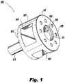
Fig. 1 is a perspective view of an embodiment of a piston in accordance with this disclosure; and -
Fig. 2 is schematic cross-sectional view of an embodiment of a ram air turbine (RAT) actuator in accordance with this disclosure. -
Fig. 3 is a schematic cross-sectional view of a RAT actuator showing a progression from attached to deployed. - Reference will now be made to the drawings wherein like reference numerals identify similar structural features or aspects of the subject disclosure. For purposes of explanation and illustration, and not limitation, an illustrative view of an embodiment of a ram air turbine (RAT) actuator piston in accordance with the disclosure is shown in
Fig. 1 and is designated generally byreference character 100. Other embodiments and/or aspects of this disclosure are shown inFigs. 2-3 . Certain embodiments described herein can be used to dissipate vibratory loads in a RAT system in the stowed position, for example. - Referring to
Fig. 1 , a ram air turbine (RAT)actuator piston 100 can include abody 101 defining a piston structure (e.g., a cylindrical shape as shown, or any other suitable shape). Thebody 101 can have aninner cavity 103. - The
piston 100 can include one or more dampingholes 109 axially defined through thebody 101 to theinner cavity 103 and alock rod hole 111 defined axially through thebody 101 to theinner cavity 103. Thelock rod hole 111 can have a larger flow area than one or more of the one or more dampingholes 109, for example. Referring additionally toFig. 2 , thelock rod hole 111 can be configured to receive alock rod 213 of aRAT actuator 200 to at least partially block flow through thelock rod hole 111. - In certain embodiments, the
piston 100 can include one or morelock pawl windows 105 configured to receive one or more lock pawls (e.g., one or more rollers, not shown) of aRAT actuator 200. The one or morelock pawl windows 105 can be radially defined through thebody 101 from a radiallyouter surface 107 of thebody 101 to theinner cavity 103. In certain embodiments, thelock rod hole 111 can be configured to receive thelock rod 213 to support the lock pawls when thelock rod 213 is in a locked position (e.g., as shown inFig. 2 ) in addition to at least partially blocking flow through thelock rod hole 111. - To support the lock pawls, the
lock rod 213 can extend into thecavity 103 in the locked position and contact the lock pawls to push the lock pawls radially outward to contact a surroundinguplock mechanism 215 to block theuplock mechanism 215 from moving relative to thepiston 100. One having ordinary skill in the art in view of this disclosure understands that any suitable construction for theuplock mechanism 215 and lock pawls are contemplated herein. Embodiments may include lock pawls and/or the uplock mechanism dimensioned to allow some motion of thepiston 100 back and forth to allow the piston to displace or travel axially a small distance relative to the uplock mechanism such that damping flow can flow through the dampingholes 109 back and forth. For example, the lock pawls and/or theuplock mechanism 215 may be dimensioned to include from about 40 thousands of an inch to about 150 thousands of an inch in axial play (e.g., which is about 4 times to about 5 times as much play in existing systems). - The one or more damping
holes 109 can be configured to allow flow through (back and forth when vibrating) the dampingholes 109 in the locked position to allow theRAT actuator piston 100 to move within theRAT actuator 200 in the locked position to dissipate vibratory loads. The one or more dampingholes 109 can include any suitable size and shape (e.g., about 1/10th the diameter of thelock rod hole 111 or any other suitable size). - As shown, the one or more damping
holes 109 can be defined between an axiallyouter face 115 of thebody 101 and theinner cavity 103. The one or more dampingholes 109 can be radially positioned between the outerradial surface 107 ofbody 101 and thelock rod hole 111 or in any other suitable position. Similarly, thelock rod hole 111 can be defined between the axiallyouter face 115 of thebody 101 and theinner cavity 103. Any other suitable location for the dampingholes 109 and thelock rod hole 111 is contemplated herein. - The one or more damping
holes 109 can include a plurality of dampingholes 109 as shown (e.g., 8 or more). Thepiston 100 can include apiston rod 117 extending from thebody 101 forming part of or configured to connect to arod end 219. Therod end 219 can be configured to connect to the RAT. - In accordance with at least one aspect of this disclosure, as shown in
Fig. 2 , a ram air turbine (RAT)actuator 200 can include anuplock mechanism 215 defining achamber 221 and configured to be retained in an uplock axial position by one or more lock pawls (not shown). The RAT actuator 200 can include aRAT actuator piston 100 disposed within theuplock mechanism chamber 221 configured to dissipate vibrational energy applied to thepiston 100 in a locked position. In certain embodiments, theRAT actuator piston 100 can be any suitable piston as disclosed herein (e.g., as described above). Any other suitable embodiment of a piston configured to dissipate vibrational energy is contemplated herein. - The RAT actuator 200 can include one or more lock pawls (not shown) disposed in the
lock pawl windows 105. The RAT actuator 200 can include thelock rod 213 disposed therein and configured to move axially through thelock rod hole 111 and to support the one or more lock pawls in the locked position to maintain the uplock position of the RAT. Thelock rod 213 is configured to move axially out of the lock rod hole 111 (e.g., in direction 223) to allow radially inward movement of the one or more lock pawls in an unlocked position such that the lock pawls disengage theuplock mechanism 215 to allow extension of theRAT actuator 200. While certain embodiments can utilize a lock pawl type mechanism for retaining the piston, any other suitable mechanism is contemplated herein. For example, any mechanism that prevents a spring preloaded actuator from deploying is contemplated herein. - The RAT actuator 200 can include a
valve housing 225 operatively connected to thelock rod 213 to move thelock rod 213 axially. Any suitable construction of thevalve housing 225 is contemplated herein. The RAT actuator 200 can include at least oneactuator spring 227 configured to extend theRAT actuator 200 in the unlocked position of the lock rod 213 (e.g., to deploy the RAT as appreciated by those having ordinary skill in the art). The RAT actuator 200 can include any suitable components as appreciated by those having ordinary skill in the art in view of this disclosure. - In accordance with at least one aspect of this disclosure, a ram air turbine (RAT) can include any suitable embodiment of a RAT actuator disclosed herein (e.g., as described above). Any other suitable embodiment of a RAT actuator is contemplated herein. Certain embodiments of the RAT include any other suitable components (e.g., a turbine, a shaft, a generator, etc.) for a RAT as appreciated by those having ordinary skill in the art in view of this disclosure.
- Traditional systems are not capable of dissipating vibration. In certain embodiments, the RAT can include lock pawls and/or an interface thereof (e.g., in the uplock mechanism) that is dimensioned to allow the piston to vibrate, and the piston can include damper holes that allow damping of vibration of the piston thereby dissipating the vibrational energy in the fluid (e.g., hydraulic fluid) within the uplock mechanism. During the deployment process, the embodiments allow opening of the larger lock rod hole by remove of the lock rod therefrom to allow fast deployment of the piston such that both dissipation and fast deployment can be achieved.
-
Fig. 3 , shows a stowed actuator, an actuator once a signal to deploy the actuator to deploy has been given and plunger moved to the right to open orifice and disengage locking mechanism and finally a deployed actuator. - As shown, embodiments can allow the lock rod to move (e.g., to the right as shown) to open the lock rod hole in piston to allow easy flow of fluid (e.g., oil) and to disengage lock pawls from the uplock mechanism housing to allow movement relative to the piston. The valve housing/chamber can pull the lock rod and facilitate restowing of the actuator after deployment.
- Embodiments include a damper in the actuator which can damp out the low frequency response in the stowed position for HLSD (high-level-short-duration) and windmilling loading which are typically stowed only requirements. HLSD and windmilling are loadings due rotating imbalance due to loss of a fan blade on one of an aircraft's main engines. Embodiments provide play in the stowed position of the actuator such that enough damping can be provided for the specific design.
- Embodiments provide damping while preventing increase in deployment time such that damping is provided in the stowed position of the RAT while not negatively impacting deployment time. For example, before the uplock mechanism is released, the flow restriction at the piston will be removed by opening the lock rod hole, thereby preventing any significant portion of the deployment spring's energy from being spent on overcoming friction. Embodiments reduce loads in the RAT and the RAT actuator leading to more robust designs, reduced weight, and reduced cost since addition of an external uplock is not necessary, for example.
- Those having ordinary skill in the art understand that any numerical values disclosed herein can be exact values or can be values within a range. Further, any terms of approximation (e.g., "about", "approximately", "around") used in this disclosure can mean the stated value within a range. For example, in certain embodiments, the range can be within (plus or minus) 20%, or within 10%, or within 5%, or within 2%, or within any other suitable percentage or number as appreciated by those having ordinary skill in the art (e.g., for known tolerance limits or error ranges).
- Any suitable combination(s) of any disclosed embodiments and/or any suitable portion(s) thereof are contemplated herein as appreciated by those having ordinary skill in the art.
- The embodiments of the present disclosure, as described above and shown in the drawings, provide for improvement in the art to which they pertain. While the subject disclosure includes reference to certain embodiments, those skilled in the art will readily appreciate that changes and/or modifications may be made thereto without departing from the spirit and scope of the subject disclosure.
Claims (15)
- A ram air turbine (RAT) actuator piston (100), comprising:a body (101) defining a piston structure having an inner cavity (103);one or more damping holes (109) axially defined through the body (101) to the inner cavity (103); anda lock rod hole (111) defined axially through the body (101) to the inner cavity (103), wherein the lock rod hole (111) has a larger flow area than one or more of the one or more damping holes (109), wherein the lock rod hole (111) is configured to receive a lock rod (213) of a RAT actuator (200) to at least partially block flow through the lock rod hole (111) when the lock rod (213) is in a locked position, wherein the one or more damping holes (109) are configured to allow flow through the damping holes (109) in the locked position to allow the RAT actuator piston (100) to move within the RAT actuator (200) in the locked position to dissipate vibratory loads.
- The piston of claim 1, further comprising one or more lock pawl windows (105) radially defined through the body (101) from a radially outer surface of the body (101) to the inner cavity (103), the one or more lock pawl windows (105) configured to receive one or more lock pawls of a RAT actuator, wherein the lock rod hole (111) is configured to receive a lock rod of a RAT actuator (200) to additionally support the lock pawls when the lock rod (213) is in a locked position.
- The piston of claim 1 or 2, wherein the one or more damping holes (109) are defined between an axially outer face of the body (101) and the inner cavity (103), and optionally
wherein the lock rod hole is defined between the axially outer face of the body (101) and the inner cavity (103). - The piston of any preceding claim, wherein the one or more damping holes (109) includes a plurality of damping holes (109), and optionally
further comprising a piston rod (117) forming part of or configured to connect to a rod end (219) extending from the body (101). - A ram air turbine (RAT) actuator (200), comprising:an uplock mechanism defining a chamber (221) and configured to be retained in an uplock axial position; anda RAT actuator piston (100) disposed within the uplock mechanism chamber (221) configured to dissipate vibrational energy applied to the piston (100) in a locked position.
- The RAT actuator of claim 5, wherein the RAT actuator piston (100) includes:a body (101) defining a piston structure having an inner cavity (103);one or more lock pawl windows (105) radially defined through the body (101) from a radially outer surface of the body (101) to the inner cavity (103), the one or more lock pawl windows (105) configured to receive one or more lock pawls of a RAT actuator (200);one or more damping holes (109) axially defined through the body (101) to the inner cavity (103); anda lock rod hole (111) defined axially through the body (101) to the inner cavity (103), wherein the lock rod hole (111) has a larger flow area than one or more of the one or more damping holes (109), wherein the lock rod hole (111) is configured to receive a lock rod of a RAT actuator (200) to at least partially block flow through the lock rod hole (111) and support the lock pawls when the lock rod (213) is in a locked position, wherein the one or more damping holes are configured to allow flow through the damping holes (109) in the locked position to allow the RAT actuator piston (100) to move within the RAT actuator (200) in the locked position to dissipate vibratory loads.
- The RAT actuator of claim 6, further comprising the one or more lock pawls disposed in the lock pawl windows (105).
- The RAT actuator of claim 7, further comprising the lock rod (213) disposed therein and configured to move axially through the lock rod hole (111) and to support the one or more lock pawls in the locked position to maintain the uplock position of the RAT, and to allow radially inward movement of the one or more lock pawls in an unlocked position such that the lock pawls disengage the uplock mechanism to allow extension of the RAT actuator (200).
- The RAT actuator of clam 8, further comprising a valve housing operatively connected to the lock rod to move the lock rod axially.
- The RAT actuator of claim 9, further comprising at least one actuator spring configured to extend the RAT actuator in the unlocked position.
- A ram air turbine (RAT), comprising:
a RAT actuator (200) having an uplock mechanism defining a chamber (221) and configured to be retained in an uplock axial position, and a RAT actuator piston (100) disposed within the uplock mechanism chamber (221) configured to dissipate vibrational energy applied to the piston in a locked position. - The RAT of claim 11, wherein the RAT actuator piston includes:a body (101) defining a piston structure having an inner cavity (103);one or more lock pawl windows (105) radially defined through the body (101) from a radially outer surface of the body (101) to the inner cavity (103), the one or more lock pawl windows (105) configured to receive one or more lock pawls of a RAT actuator (200);one or more damping holes (109) axially defined through the body (101) to the inner cavity (103); anda lock rod hole (111) defined axially through the body (101) to the inner cavity (103), wherein the lock rod hole (111) has a larger flow area than one or more of the one or more damping holes (109), wherein the lock rod hole (111) is configured to receive a lock rod of a RAT actuator (200) to at least partially block flow through the lock rod hole (111) and support the lock pawls when the lock rod is in a locked position, wherein the one or more damping holes (109) are configured to allow flow through the damping holes (109) in the locked position to allow the RAT actuator piston (100) to move within the RAT actuator (200) in the locked position to dissipate vibratory loads.
- The RAT of claim 12, further comprising the one or more lock pawls disposed in the lock pawl windows (105).
- The RAT of claim 13, further comprising the lock rod (111) disposed therein and configured to move axially through the lock rod hole (111) and to support the one or more lock pawls in the locked position to maintain the uplock position of the RAT, and to allow radially inward movement of the one or more lock pawls in an unlocked position such that the lock pawls disengage the uplock mechanism to allow extension of the RAT actuator.
- The RAT of claim 14, further comprising a valve housing operatively connected to the lock rod to move the lock rod (213) axially, and optionally
further comprising at least one actuator spring (227) configured to extend the RAT actuator (200) in the unlocked position.
Applications Claiming Priority (1)
| Application Number | Priority Date | Filing Date | Title |
|---|---|---|---|
| US16/361,811 US11014688B2 (en) | 2019-03-22 | 2019-03-22 | Ram air turbine actuators having damping |
Publications (2)
| Publication Number | Publication Date |
|---|---|
| EP3719345A1 true EP3719345A1 (en) | 2020-10-07 |
| EP3719345B1 EP3719345B1 (en) | 2025-07-02 |
Family
ID=68609981
Family Applications (1)
| Application Number | Title | Priority Date | Filing Date |
|---|---|---|---|
| EP19209717.8A Active EP3719345B1 (en) | 2019-03-22 | 2019-11-18 | Ram air turbine actuators having damping |
Country Status (2)
| Country | Link |
|---|---|
| US (1) | US11014688B2 (en) |
| EP (1) | EP3719345B1 (en) |
Families Citing this family (2)
| Publication number | Priority date | Publication date | Assignee | Title |
|---|---|---|---|---|
| US11603212B1 (en) | 2021-11-04 | 2023-03-14 | Hamilton Sundstrand Corporation | Strut with inner damper rod |
| EP4286282B1 (en) * | 2022-06-02 | 2024-12-18 | Hamilton Sundstrand Corporation | Actuator release mechanism |
Citations (2)
| Publication number | Priority date | Publication date | Assignee | Title |
|---|---|---|---|---|
| US3022771A (en) * | 1959-03-03 | 1962-02-27 | Clemco Aero Products Inc | Unlocking mechanism for a two-part extensible strut |
| US20130327207A1 (en) * | 2012-06-06 | 2013-12-12 | Gary SASSCER | Electromechanical actuator damping arrangement for ram air turbine |
Family Cites Families (4)
| Publication number | Priority date | Publication date | Assignee | Title |
|---|---|---|---|---|
| EP2397760B1 (en) | 2010-06-16 | 2020-11-18 | Ansaldo Energia IP UK Limited | Damper Arrangement and Method for Designing Same |
| US9415880B2 (en) * | 2013-10-09 | 2016-08-16 | Hamilton Sundstrand Corporation | Actuator for rat deployment |
| US10077118B2 (en) | 2016-06-06 | 2018-09-18 | Hamilton Sundstrand Corporation | Integral rat generator cooling holes |
| US10550867B2 (en) | 2017-07-03 | 2020-02-04 | Hamilton Sundstrand Corporation | Ram air turbine structures for temperature dependent damping |
-
2019
- 2019-03-22 US US16/361,811 patent/US11014688B2/en active Active
- 2019-11-18 EP EP19209717.8A patent/EP3719345B1/en active Active
Patent Citations (2)
| Publication number | Priority date | Publication date | Assignee | Title |
|---|---|---|---|---|
| US3022771A (en) * | 1959-03-03 | 1962-02-27 | Clemco Aero Products Inc | Unlocking mechanism for a two-part extensible strut |
| US20130327207A1 (en) * | 2012-06-06 | 2013-12-12 | Gary SASSCER | Electromechanical actuator damping arrangement for ram air turbine |
Also Published As
| Publication number | Publication date |
|---|---|
| EP3719345B1 (en) | 2025-07-02 |
| US11014688B2 (en) | 2021-05-25 |
| US20200298992A1 (en) | 2020-09-24 |
Similar Documents
| Publication | Publication Date | Title |
|---|---|---|
| CN114466792B (en) | Vibration Absorbing Column | |
| EP3719345B1 (en) | Ram air turbine actuators having damping | |
| CA2789472C (en) | Vibration isolation system | |
| US10946986B1 (en) | Mechanism for increasing jettison clearance | |
| EP2634095A2 (en) | Launch lock assemblies including axial gap amplification devices and spacecraft isolation systems including the same | |
| CN107150789B (en) | Aircraft landing gear assembly | |
| US8840062B2 (en) | Pylon mounting system with vibration isolation | |
| EP2985472B1 (en) | Stow lock pawl for a rat actuator | |
| CN103375198B (en) | Turbine lock plunger for ram air turbine assembly | |
| CN109882534A (en) | A kind of vibration isolator | |
| EP3196126B1 (en) | Locking and unlocking mechanism | |
| JP5948384B2 (en) | Propeller assembly and propeller blade fixing assembly | |
| US10317929B2 (en) | Locking and unlocking mechanism | |
| ITTO20010394A1 (en) | LOCKING AND UNLOCKING MECHANISM FOR MISSILE STABILIZER FIN, INCLUDING A MECHANICAL FORCE AMPLIFIER. | |
| US10132245B2 (en) | Fusible link with coulomb damping | |
| JP2019209965A (en) | Electromechanical point separation system | |
| US9783287B2 (en) | Aircraft spring assembly | |
| JP6356848B2 (en) | Storage / extension of landing gear in aircraft | |
| EP2450592B1 (en) | Dampening device | |
| EP4316990B1 (en) | Adjustable latch hook with indexing bearing block | |
| CN104309821A (en) | Repeatable maglev flywheel locking device | |
| US9260194B2 (en) | Gimbal pin for jet propulsion system | |
| US2856143A (en) | Compressible landing gear construction | |
| EP4177165B1 (en) | Strut for ram air turbine with inner damper rod | |
| CN113758378B (en) | Variable-stiffness damping supporting mechanism for reusable rocket |
Legal Events
| Date | Code | Title | Description |
|---|---|---|---|
| PUAI | Public reference made under article 153(3) epc to a published international application that has entered the european phase |
Free format text: ORIGINAL CODE: 0009012 |
|
| STAA | Information on the status of an ep patent application or granted ep patent |
Free format text: STATUS: THE APPLICATION HAS BEEN PUBLISHED |
|
| AK | Designated contracting states |
Kind code of ref document: A1 Designated state(s): AL AT BE BG CH CY CZ DE DK EE ES FI FR GB GR HR HU IE IS IT LI LT LU LV MC MK MT NL NO PL PT RO RS SE SI SK SM TR |
|
| AX | Request for extension of the european patent |
Extension state: BA ME |
|
| STAA | Information on the status of an ep patent application or granted ep patent |
Free format text: STATUS: REQUEST FOR EXAMINATION WAS MADE |
|
| 17P | Request for examination filed |
Effective date: 20210407 |
|
| RBV | Designated contracting states (corrected) |
Designated state(s): AL AT BE BG CH CY CZ DE DK EE ES FI FR GB GR HR HU IE IS IT LI LT LU LV MC MK MT NL NO PL PT RO RS SE SI SK SM TR |
|
| STAA | Information on the status of an ep patent application or granted ep patent |
Free format text: STATUS: EXAMINATION IS IN PROGRESS |
|
| 17Q | First examination report despatched |
Effective date: 20230822 |
|
| REG | Reference to a national code |
Ref country code: DE Ref legal event code: R079 Free format text: PREVIOUS MAIN CLASS: F16F0009320000 Ipc: B64D0041000000 Ref country code: DE Ref legal event code: R079 Ref document number: 602019071878 Country of ref document: DE Free format text: PREVIOUS MAIN CLASS: F16F0009320000 Ipc: B64D0041000000 |
|
| GRAP | Despatch of communication of intention to grant a patent |
Free format text: ORIGINAL CODE: EPIDOSNIGR1 |
|
| STAA | Information on the status of an ep patent application or granted ep patent |
Free format text: STATUS: GRANT OF PATENT IS INTENDED |
|
| RIC1 | Information provided on ipc code assigned before grant |
Ipc: F16F 9/56 20060101ALI20240126BHEP Ipc: F15B 15/26 20060101ALI20240126BHEP Ipc: F16F 9/32 20060101ALI20240126BHEP Ipc: F15B 21/00 20060101ALI20240126BHEP Ipc: F15B 15/14 20060101ALI20240126BHEP Ipc: B64D 41/00 20060101AFI20240126BHEP |
|
| INTG | Intention to grant announced |
Effective date: 20240214 |
|
| GRAJ | Information related to disapproval of communication of intention to grant by the applicant or resumption of examination proceedings by the epo deleted |
Free format text: ORIGINAL CODE: EPIDOSDIGR1 |
|
| STAA | Information on the status of an ep patent application or granted ep patent |
Free format text: STATUS: EXAMINATION IS IN PROGRESS |
|
| INTC | Intention to grant announced (deleted) | ||
| GRAP | Despatch of communication of intention to grant a patent |
Free format text: ORIGINAL CODE: EPIDOSNIGR1 |
|
| STAA | Information on the status of an ep patent application or granted ep patent |
Free format text: STATUS: GRANT OF PATENT IS INTENDED |
|
| INTG | Intention to grant announced |
Effective date: 20250129 |
|
| GRAS | Grant fee paid |
Free format text: ORIGINAL CODE: EPIDOSNIGR3 |
|
| GRAA | (expected) grant |
Free format text: ORIGINAL CODE: 0009210 |
|
| STAA | Information on the status of an ep patent application or granted ep patent |
Free format text: STATUS: THE PATENT HAS BEEN GRANTED |
|
| AK | Designated contracting states |
Kind code of ref document: B1 Designated state(s): AL AT BE BG CH CY CZ DE DK EE ES FI FR GB GR HR HU IE IS IT LI LT LU LV MC MK MT NL NO PL PT RO RS SE SI SK SM TR |
|
| REG | Reference to a national code |
Ref country code: GB Ref legal event code: FG4D |
|
| REG | Reference to a national code |
Ref country code: CH Ref legal event code: EP |
|
| REG | Reference to a national code |
Ref country code: DE Ref legal event code: R096 Ref document number: 602019071878 Country of ref document: DE |
|
| REG | Reference to a national code |
Ref country code: IE Ref legal event code: FG4D |
|
| REG | Reference to a national code |
Ref country code: NL Ref legal event code: MP Effective date: 20250702 |
|
| PG25 | Lapsed in a contracting state [announced via postgrant information from national office to epo] |
Ref country code: PT Free format text: LAPSE BECAUSE OF FAILURE TO SUBMIT A TRANSLATION OF THE DESCRIPTION OR TO PAY THE FEE WITHIN THE PRESCRIBED TIME-LIMIT Effective date: 20251103 |
|
| PG25 | Lapsed in a contracting state [announced via postgrant information from national office to epo] |
Ref country code: NL Free format text: LAPSE BECAUSE OF FAILURE TO SUBMIT A TRANSLATION OF THE DESCRIPTION OR TO PAY THE FEE WITHIN THE PRESCRIBED TIME-LIMIT Effective date: 20250702 |
|
| REG | Reference to a national code |
Ref country code: AT Ref legal event code: MK05 Ref document number: 1809002 Country of ref document: AT Kind code of ref document: T Effective date: 20250702 |
|
| PG25 | Lapsed in a contracting state [announced via postgrant information from national office to epo] |
Ref country code: IS Free format text: LAPSE BECAUSE OF FAILURE TO SUBMIT A TRANSLATION OF THE DESCRIPTION OR TO PAY THE FEE WITHIN THE PRESCRIBED TIME-LIMIT Effective date: 20251102 |
|
| PG25 | Lapsed in a contracting state [announced via postgrant information from national office to epo] |
Ref country code: NO Free format text: LAPSE BECAUSE OF FAILURE TO SUBMIT A TRANSLATION OF THE DESCRIPTION OR TO PAY THE FEE WITHIN THE PRESCRIBED TIME-LIMIT Effective date: 20251002 |
|
| REG | Reference to a national code |
Ref country code: LT Ref legal event code: MG9D |
|
| PG25 | Lapsed in a contracting state [announced via postgrant information from national office to epo] |
Ref country code: AT Free format text: LAPSE BECAUSE OF FAILURE TO SUBMIT A TRANSLATION OF THE DESCRIPTION OR TO PAY THE FEE WITHIN THE PRESCRIBED TIME-LIMIT Effective date: 20250702 |
|
| PG25 | Lapsed in a contracting state [announced via postgrant information from national office to epo] |
Ref country code: FI Free format text: LAPSE BECAUSE OF FAILURE TO SUBMIT A TRANSLATION OF THE DESCRIPTION OR TO PAY THE FEE WITHIN THE PRESCRIBED TIME-LIMIT Effective date: 20250702 |
|
| PG25 | Lapsed in a contracting state [announced via postgrant information from national office to epo] |
Ref country code: HR Free format text: LAPSE BECAUSE OF FAILURE TO SUBMIT A TRANSLATION OF THE DESCRIPTION OR TO PAY THE FEE WITHIN THE PRESCRIBED TIME-LIMIT Effective date: 20250702 |
|
| PGFP | Annual fee paid to national office [announced via postgrant information from national office to epo] |
Ref country code: FR Payment date: 20251022 Year of fee payment: 7 |
|
| PG25 | Lapsed in a contracting state [announced via postgrant information from national office to epo] |
Ref country code: GR Free format text: LAPSE BECAUSE OF FAILURE TO SUBMIT A TRANSLATION OF THE DESCRIPTION OR TO PAY THE FEE WITHIN THE PRESCRIBED TIME-LIMIT Effective date: 20251003 |
|
| PG25 | Lapsed in a contracting state [announced via postgrant information from national office to epo] |
Ref country code: SE Free format text: LAPSE BECAUSE OF FAILURE TO SUBMIT A TRANSLATION OF THE DESCRIPTION OR TO PAY THE FEE WITHIN THE PRESCRIBED TIME-LIMIT Effective date: 20250702 Ref country code: CZ Free format text: LAPSE BECAUSE OF FAILURE TO SUBMIT A TRANSLATION OF THE DESCRIPTION OR TO PAY THE FEE WITHIN THE PRESCRIBED TIME-LIMIT Effective date: 20250702 |
|
| PG25 | Lapsed in a contracting state [announced via postgrant information from national office to epo] |
Ref country code: LV Free format text: LAPSE BECAUSE OF FAILURE TO SUBMIT A TRANSLATION OF THE DESCRIPTION OR TO PAY THE FEE WITHIN THE PRESCRIBED TIME-LIMIT Effective date: 20250702 |
|
| PG25 | Lapsed in a contracting state [announced via postgrant information from national office to epo] |
Ref country code: PL Free format text: LAPSE BECAUSE OF FAILURE TO SUBMIT A TRANSLATION OF THE DESCRIPTION OR TO PAY THE FEE WITHIN THE PRESCRIBED TIME-LIMIT Effective date: 20250702 Ref country code: BG Free format text: LAPSE BECAUSE OF FAILURE TO SUBMIT A TRANSLATION OF THE DESCRIPTION OR TO PAY THE FEE WITHIN THE PRESCRIBED TIME-LIMIT Effective date: 20250702 |
|
| PG25 | Lapsed in a contracting state [announced via postgrant information from national office to epo] |
Ref country code: RS Free format text: LAPSE BECAUSE OF FAILURE TO SUBMIT A TRANSLATION OF THE DESCRIPTION OR TO PAY THE FEE WITHIN THE PRESCRIBED TIME-LIMIT Effective date: 20251002 |
|
| PG25 | Lapsed in a contracting state [announced via postgrant information from national office to epo] |
Ref country code: ES Free format text: LAPSE BECAUSE OF FAILURE TO SUBMIT A TRANSLATION OF THE DESCRIPTION OR TO PAY THE FEE WITHIN THE PRESCRIBED TIME-LIMIT Effective date: 20250702 |
|
| PG25 | Lapsed in a contracting state [announced via postgrant information from national office to epo] |
Ref country code: RO Free format text: LAPSE BECAUSE OF FAILURE TO SUBMIT A TRANSLATION OF THE DESCRIPTION OR TO PAY THE FEE WITHIN THE PRESCRIBED TIME-LIMIT Effective date: 20250702 |
|
| PG25 | Lapsed in a contracting state [announced via postgrant information from national office to epo] |
Ref country code: SM Free format text: LAPSE BECAUSE OF FAILURE TO SUBMIT A TRANSLATION OF THE DESCRIPTION OR TO PAY THE FEE WITHIN THE PRESCRIBED TIME-LIMIT Effective date: 20250702 |
|
| PG25 | Lapsed in a contracting state [announced via postgrant information from national office to epo] |
Ref country code: DK Free format text: LAPSE BECAUSE OF FAILURE TO SUBMIT A TRANSLATION OF THE DESCRIPTION OR TO PAY THE FEE WITHIN THE PRESCRIBED TIME-LIMIT Effective date: 20250702 |
|
| PG25 | Lapsed in a contracting state [announced via postgrant information from national office to epo] |
Ref country code: IT Free format text: LAPSE BECAUSE OF FAILURE TO SUBMIT A TRANSLATION OF THE DESCRIPTION OR TO PAY THE FEE WITHIN THE PRESCRIBED TIME-LIMIT Effective date: 20250702 |
|
| PG25 | Lapsed in a contracting state [announced via postgrant information from national office to epo] |
Ref country code: SK Free format text: LAPSE BECAUSE OF FAILURE TO SUBMIT A TRANSLATION OF THE DESCRIPTION OR TO PAY THE FEE WITHIN THE PRESCRIBED TIME-LIMIT Effective date: 20250702 Ref country code: EE Free format text: LAPSE BECAUSE OF FAILURE TO SUBMIT A TRANSLATION OF THE DESCRIPTION OR TO PAY THE FEE WITHIN THE PRESCRIBED TIME-LIMIT Effective date: 20250702 |
|
| PLBE | No opposition filed within time limit |
Free format text: ORIGINAL CODE: 0009261 |
|
| STAA | Information on the status of an ep patent application or granted ep patent |
Free format text: STATUS: NO OPPOSITION FILED WITHIN TIME LIMIT |