EP3719343A1 - Suspension system and vehicle - Google Patents
Suspension system and vehicle Download PDFInfo
- Publication number
- EP3719343A1 EP3719343A1 EP20167077.5A EP20167077A EP3719343A1 EP 3719343 A1 EP3719343 A1 EP 3719343A1 EP 20167077 A EP20167077 A EP 20167077A EP 3719343 A1 EP3719343 A1 EP 3719343A1
- Authority
- EP
- European Patent Office
- Prior art keywords
- diaphragm
- damper
- suspension system
- outer peripheral
- oil chamber
- Prior art date
- Legal status (The legal status is an assumption and is not a legal conclusion. Google has not performed a legal analysis and makes no representation as to the accuracy of the status listed.)
- Withdrawn
Links
- 239000000725 suspension Substances 0.000 title claims abstract description 93
- 238000005192 partition Methods 0.000 claims abstract description 14
- 239000000463 material Substances 0.000 claims abstract description 13
- 230000002093 peripheral effect Effects 0.000 claims description 110
- 238000013016 damping Methods 0.000 claims description 92
- 230000007246 mechanism Effects 0.000 claims description 71
- 238000007789 sealing Methods 0.000 claims description 10
- 239000007789 gas Substances 0.000 description 91
- 238000010586 diagram Methods 0.000 description 16
- 238000006243 chemical reaction Methods 0.000 description 15
- 230000006835 compression Effects 0.000 description 10
- 238000007906 compression Methods 0.000 description 10
- 230000004043 responsiveness Effects 0.000 description 6
- 230000000903 blocking effect Effects 0.000 description 4
- 239000000872 buffer Substances 0.000 description 4
- 230000007423 decrease Effects 0.000 description 4
- 238000005516 engineering process Methods 0.000 description 3
- 239000011347 resin Substances 0.000 description 3
- 229920005989 resin Polymers 0.000 description 3
- IJGRMHOSHXDMSA-UHFFFAOYSA-N Atomic nitrogen Chemical compound N#N IJGRMHOSHXDMSA-UHFFFAOYSA-N 0.000 description 2
- 230000008602 contraction Effects 0.000 description 2
- 230000003247 decreasing effect Effects 0.000 description 2
- 238000002347 injection Methods 0.000 description 2
- 239000007924 injection Substances 0.000 description 2
- 239000002184 metal Substances 0.000 description 2
- 239000011295 pitch Substances 0.000 description 2
- -1 polyethylene Polymers 0.000 description 2
- 239000004698 Polyethylene Substances 0.000 description 1
- 239000004743 Polypropylene Substances 0.000 description 1
- 230000001419 dependent effect Effects 0.000 description 1
- 238000006073 displacement reaction Methods 0.000 description 1
- 238000007667 floating Methods 0.000 description 1
- 230000001771 impaired effect Effects 0.000 description 1
- 210000002445 nipple Anatomy 0.000 description 1
- 229910052757 nitrogen Inorganic materials 0.000 description 1
- 239000004033 plastic Substances 0.000 description 1
- 229920003023 plastic Polymers 0.000 description 1
- 229920000573 polyethylene Polymers 0.000 description 1
- 229920001155 polypropylene Polymers 0.000 description 1
- 229920000915 polyvinyl chloride Polymers 0.000 description 1
- 239000004800 polyvinyl chloride Substances 0.000 description 1
- 230000001105 regulatory effect Effects 0.000 description 1
Images





Classifications
-
- B—PERFORMING OPERATIONS; TRANSPORTING
- B60—VEHICLES IN GENERAL
- B60G—VEHICLE SUSPENSION ARRANGEMENTS
- B60G17/00—Resilient suspensions having means for adjusting the spring or vibration-damper characteristics, for regulating the distance between a supporting surface and a sprung part of vehicle or for locking suspension during use to meet varying vehicular or surface conditions, e.g. due to speed or load
- B60G17/02—Spring characteristics, e.g. mechanical springs and mechanical adjusting means
- B60G17/04—Spring characteristics, e.g. mechanical springs and mechanical adjusting means fluid spring characteristics
- B60G17/0416—Spring characteristics, e.g. mechanical springs and mechanical adjusting means fluid spring characteristics regulated by varying the resiliency of hydropneumatic suspensions
- B60G17/0424—Spring characteristics, e.g. mechanical springs and mechanical adjusting means fluid spring characteristics regulated by varying the resiliency of hydropneumatic suspensions by varying the air pressure of the accumulator
-
- F—MECHANICAL ENGINEERING; LIGHTING; HEATING; WEAPONS; BLASTING
- F16—ENGINEERING ELEMENTS AND UNITS; GENERAL MEASURES FOR PRODUCING AND MAINTAINING EFFECTIVE FUNCTIONING OF MACHINES OR INSTALLATIONS; THERMAL INSULATION IN GENERAL
- F16F—SPRINGS; SHOCK-ABSORBERS; MEANS FOR DAMPING VIBRATION
- F16F9/00—Springs, vibration-dampers, shock-absorbers, or similarly-constructed movement-dampers using a fluid or the equivalent as damping medium
- F16F9/06—Springs, vibration-dampers, shock-absorbers, or similarly-constructed movement-dampers using a fluid or the equivalent as damping medium using both gas and liquid
- F16F9/08—Springs, vibration-dampers, shock-absorbers, or similarly-constructed movement-dampers using a fluid or the equivalent as damping medium using both gas and liquid where gas is in a chamber with a flexible wall
- F16F9/096—Springs, vibration-dampers, shock-absorbers, or similarly-constructed movement-dampers using a fluid or the equivalent as damping medium using both gas and liquid where gas is in a chamber with a flexible wall comprising a hydropneumatic accumulator of the membrane type provided on the upper or the lower end of a damper or separately from or laterally on the damper
-
- B—PERFORMING OPERATIONS; TRANSPORTING
- B60—VEHICLES IN GENERAL
- B60G—VEHICLE SUSPENSION ARRANGEMENTS
- B60G15/00—Resilient suspensions characterised by arrangement, location or type of combined spring and vibration damper, e.g. telescopic type
- B60G15/02—Resilient suspensions characterised by arrangement, location or type of combined spring and vibration damper, e.g. telescopic type having mechanical spring
- B60G15/06—Resilient suspensions characterised by arrangement, location or type of combined spring and vibration damper, e.g. telescopic type having mechanical spring and fluid damper
- B60G15/062—Resilient suspensions characterised by arrangement, location or type of combined spring and vibration damper, e.g. telescopic type having mechanical spring and fluid damper the spring being arranged around the damper
-
- B—PERFORMING OPERATIONS; TRANSPORTING
- B60—VEHICLES IN GENERAL
- B60G—VEHICLE SUSPENSION ARRANGEMENTS
- B60G15/00—Resilient suspensions characterised by arrangement, location or type of combined spring and vibration damper, e.g. telescopic type
- B60G15/08—Resilient suspensions characterised by arrangement, location or type of combined spring and vibration damper, e.g. telescopic type having fluid spring
- B60G15/12—Resilient suspensions characterised by arrangement, location or type of combined spring and vibration damper, e.g. telescopic type having fluid spring and fluid damper
-
- B—PERFORMING OPERATIONS; TRANSPORTING
- B60—VEHICLES IN GENERAL
- B60G—VEHICLE SUSPENSION ARRANGEMENTS
- B60G21/00—Interconnection systems for two or more resiliently-suspended wheels, e.g. for stabilising a vehicle body with respect to acceleration, deceleration or centrifugal forces
- B60G21/02—Interconnection systems for two or more resiliently-suspended wheels, e.g. for stabilising a vehicle body with respect to acceleration, deceleration or centrifugal forces permanently interconnected
- B60G21/06—Interconnection systems for two or more resiliently-suspended wheels, e.g. for stabilising a vehicle body with respect to acceleration, deceleration or centrifugal forces permanently interconnected fluid
- B60G21/073—Interconnection systems for two or more resiliently-suspended wheels, e.g. for stabilising a vehicle body with respect to acceleration, deceleration or centrifugal forces permanently interconnected fluid between wheels on the same axle but on different sides of the vehicle, i.e. the left and right wheel suspensions being interconnected
-
- B—PERFORMING OPERATIONS; TRANSPORTING
- B60—VEHICLES IN GENERAL
- B60G—VEHICLE SUSPENSION ARRANGEMENTS
- B60G2200/00—Indexing codes relating to suspension types
- B60G2200/10—Independent suspensions
- B60G2200/14—Independent suspensions with lateral arms
- B60G2200/144—Independent suspensions with lateral arms with two lateral arms forming a parallelogram
-
- B—PERFORMING OPERATIONS; TRANSPORTING
- B60—VEHICLES IN GENERAL
- B60G—VEHICLE SUSPENSION ARRANGEMENTS
- B60G2202/00—Indexing codes relating to the type of spring, damper or actuator
- B60G2202/10—Type of spring
- B60G2202/15—Fluid spring
- B60G2202/154—Fluid spring with an accumulator
-
- B—PERFORMING OPERATIONS; TRANSPORTING
- B60—VEHICLES IN GENERAL
- B60G—VEHICLE SUSPENSION ARRANGEMENTS
- B60G2202/00—Indexing codes relating to the type of spring, damper or actuator
- B60G2202/30—Spring/Damper and/or actuator Units
- B60G2202/31—Spring/Damper and/or actuator Units with the spring arranged around the damper, e.g. MacPherson strut
- B60G2202/312—The spring being a wound spring
-
- B—PERFORMING OPERATIONS; TRANSPORTING
- B60—VEHICLES IN GENERAL
- B60G—VEHICLE SUSPENSION ARRANGEMENTS
- B60G2204/00—Indexing codes related to suspensions per se or to auxiliary parts
- B60G2204/80—Interactive suspensions; arrangement affecting more than one suspension unit
- B60G2204/82—Interactive suspensions; arrangement affecting more than one suspension unit left and right unit on same axle
-
- B—PERFORMING OPERATIONS; TRANSPORTING
- B60—VEHICLES IN GENERAL
- B60G—VEHICLE SUSPENSION ARRANGEMENTS
- B60G2204/00—Indexing codes related to suspensions per se or to auxiliary parts
- B60G2204/80—Interactive suspensions; arrangement affecting more than one suspension unit
- B60G2204/83—Type of interconnection
- B60G2204/8304—Type of interconnection using a fluid
-
- B—PERFORMING OPERATIONS; TRANSPORTING
- B60—VEHICLES IN GENERAL
- B60G—VEHICLE SUSPENSION ARRANGEMENTS
- B60G2206/00—Indexing codes related to the manufacturing of suspensions: constructional features, the materials used, procedures or tools
- B60G2206/01—Constructional features of suspension elements, e.g. arms, dampers, springs
- B60G2206/40—Constructional features of dampers and/or springs
- B60G2206/41—Dampers
-
- B—PERFORMING OPERATIONS; TRANSPORTING
- B60—VEHICLES IN GENERAL
- B60G—VEHICLE SUSPENSION ARRANGEMENTS
- B60G2300/00—Indexing codes relating to the type of vehicle
- B60G2300/32—Track vehicles
- B60G2300/322—Snowmobiles
Definitions
- the present invention relates to a suspension system.
- Such suspension system can be included in a vehicle such as a four-wheeled vehicle or a snowmobile.
- JP 2017-136918A and JP H8-132846A disclose a suspension system having an intermediate unit disposed between a right damper and a left damper.
- the intermediate unit has an oil chamber (referred to as “intermediate oil chamber”) and a gas chamber (referred to as “intermediate gas chamber”) partitioned by a free piston.
- the free piston can move in an axial direction in a case (cylinder) forming the intermediate unit according to expansion and contraction of the intermediate oil chamber.
- the intermediate oil chamber is connected to oil chambers of left and right dampers.
- connection allow oil flow between the oil chamber of each damper and the intermediate oil chamber and oil flow between the oil chambers of the left and right dampers via the intermediate oil chamber.
- Such an intermediate unit improves a damping function at a time when a wheel rides on a bump and a damping function at time when a vehicle turns.
- the present invention will now be described by referencing the appended figures representing embodiments.
- a suspension system 10 illustrated in FIG. 1 and the like will be described as an example of a suspension system proposed in the present disclosure.
- the suspension system 10 is mounted on vehicles such as snowmobiles and four-wheeled vehicles.
- the four-wheeled vehicle includes, for example, a passenger car, an All Terrain Vehicle (ATV), a Recreational Off-highway Vehicle (ROV), a golf cart, and the like.
- ATV All Terrain Vehicle
- ROV Recreational Off-highway Vehicle
- directions indicated by X1 and X2 in FIG. 1 are referred to as right and left, respectively, and directions indicated by Z1 and Z2 in FIG. 1 are referred to as upper and lower, respectively.
- the directions indicated by Y1 and Y2 in FIG. 4A are referred to as front and rear, respectively. Note that these directions refer to illustration of the figures, does not indicate technical limitation of the present invention, and does not limit the position and the orientation of the suspension system in vehicles.
- the suspension system 10 has two suspensions 50R and 50L.
- the suspensions 50R and 50L are respectively configured by dampers 51 R and 51 L and springs 59 (see FIG. 2 ).
- the suspension 50R is disposed, for example, in the right direction of a vehicle body and buffers up and down movement of a right ski or a right wheel (in this specification, a member which is in contact with a snow surface or a road surface and supports the vehicle body, such as a ski and a wheel, is referred to as a vehicle body support member).
- the suspension 50L is disposed, for example, in the left direction of the vehicle body and buffers up and down movement of the left vehicle body support member.
- damper 51R is referred to as “right damper” (first damper), and the damper 51L is referred to as “left damper” (second damper).
- first damper first damper
- second damper second damper
- the left damper 51L includes a cylinder 52 and a piston rod 53.
- the cylinder 52 includes oil chambers R1 and R2 in which oil is filled.
- the piston rod 53 has, at its end, a piston 54 which partitions the oil chambers R1 and R2.
- the piston 54 and/or the piston rod 53 include a damping force generating mechanism (71L) which generates a damping force when they move relative to the cylinder 52.
- the right damper 51R has the same structure as the left damper 51L. That is, the right damper 51R also includes a cylinder 52, a piston rod 53, a piston 54, and the damping force generating mechanism (71R).
- an example of the structure of the dampers 51 R and 51L will be described with reference to the left damper 51L illustrated in FIG. 2 .
- the piston 54 has flow paths 54a and 54b which allow oil to move between the first oil chamber R1 and the second oil chamber R2 and valve plates 54d and 54e which open or close the flow paths 54a and 54b. When the oil passes through the flow paths 54a and 54b, a damping force is generated.
- the piston rod 53 may include flow paths 53a and 53b which allow movement of oil between the first oil chamber R1 and the second oil chamber R2 and a needle valve 53e which adjusts the degree of opening of the flow paths 53a and 53b.
- a damping force is also generated when the oil passes through the flow paths 53a and 53b.
- the needle valve 53e is movable along an axial direction of the cylinder 52.
- the needle valve 53e can move to a closed position in which the needle valve 53e is fitted to the flow path 53a to close the flow path 53a, an open position in which the needle valve 53e is away from the flow path 53a to open the flow path 53a, and a position between the closed position and the open position.
- the damper 51L has an operation unit (not illustrated) connected to the needle valve 53e. A user can adjust the position of the needle valve 53e (in other words, the degree of opening of the flow paths 53a and 53a) by operating the operation unit.
- the cylinder 52 has a cap 52c at its lower (first) end for closing the cylinder 52.
- the piston rod 53 extends from the piston 54 through the second oil chamber R2 toward the cap 52c and protrudes from the cap 52c to the outside of the cylinder 52.
- Vehicles such as snowmobiles and four-wheeled vehicles have arms which connect the vehicle body support member and the vehicle body frame so that the vehicle body support member (skis or wheels) can move up and down relative to the vehicle body frame.
- an end portion (lower end) 53f of the piston rod 53 is connected to this arm and an end portion (upper end) 52a of the cylinder 52 is connected to the vehicle body frame. Therefore, the piston 54 and the piston rod 53 move relative to cylinder 52 in accordance with the up and down movement of the vehicle body support member.
- a spring sheet 52d is attached to an outer peripheral surface of the cylinder 52 and a spring sheet 53g is attached to an end portion of the piston rod 53.
- the spring 59 is held between the spring sheet 52d and the spring sheet 53g.
- the right oil flow path ER and the left oil flow path EL are configured of the pipes 81 (see FIGS. 2 and 3A ) formed of rubber or resin.
- a flow path to which the pipe 81 is connected is formed in a cap 52f (see FIG. 2 ) which closes the upper (second) end of the cylinder 52.
- the two dampers 51 R and 51L move in the same direction.
- the oil moves from the first oil chambers R1 of the two dampers 51R and 51L to the intermediate oil chamber T1 through the oil flow paths ER and EL.
- the intermediate oil chamber T1 expands.
- the two dampers 51R and 51L move in opposite directions.
- oil moves from the left damper 51L to the intermediate oil chamber T1 and oil moves from the intermediate oil chamber T1 to the right damper 51R.
- the right damper 51R is extended and the contact pressure between the right vehicle body support member and the snow or road surface is secured.
- the intermediate oil chamber T1 and the intermediate gas chamber T2 are arranged in a direction along an axis (the axis of a cylindrical main body 62 described below) Ax1 (first direction) of the intermediate case 61.
- the intermediate gas chamber T2 is formed below the intermediate oil chamber T1.
- the intermediate oil chamber T1 may be formed below the intermediate gas chamber T2.
- the intermediate gas chamber T2 is partitioned from the intermediate oil chamber T1 by the diaphragm 64.
- the diaphragm 64 is formed of a flexible material.
- the term "flexible” means that the material can be curved or bent.
- the diaphragm 64 may be stretchable or elastic owing to the flexibility.
- the material of the diaphragm 64 is, for example, rubber.
- the diaphragm 64 may be formed of a resin which can be recessed, that is, has flexibility.
- the diaphragm 64 bulges from the outer peripheral edge (lower edge) 64a toward the intermediate oil chamber T1.
- the diaphragm 64 is bulged in a direction (upward in the example described here) along the axis Ax1 of the intermediate case 61 and has a bag shape having the intermediate gas chamber T2 inside.
- the diaphragm 64 includes a body portion 64b of a cylindrical shape and a top portion 64c of a hemispherical shape located at an end portion of the body portion 64b.
- the body portion 64b is recessed (see the diagram 64 illustrated by a two-dot chain line in FIG. 4A ). Therefore, the expansion of the intermediate oil chamber T1 and the contraction of the intermediate gas chamber T2 can be smoothly generated.
- the intermediate case 61 includes the cylindrical main body 62 having an open lower end portion and a lid member 63 for closing the lower end portion.
- the cylindrical main body 62 may have a cylindrical shape having a circular or elliptical cross section or a cylindrical shape having a square cross section.
- the inner surface of the lid member 63 faces the intermediate gas chamber T2 and the intermediate gas chamber T2 is sealed by the lid member 63 and the diaphragm 64.
- the lid member 63 includes an annular or cylindrical lid outer peripheral portion 63A and a lid central portion 63B fitted inside the lid outer peripheral portion 63A.
- the capacity of the intermediate gas chamber T2 can be adjusted by moving the lid central portion 63B in the direction along the axis Ax1 with respect to the lid outer peripheral portion 63A.
- the movement of the lid central portion 63B can be performed by inserting a tool into a gas pressure adjusting hole 63h formed in the lid central portion 63B.
- the intermediate case 61 may not have such a gas volume adjusting mechanism.
- the material of the lid outer peripheral portion 63A and the material of the lid central portion 63B may be different from each other or may be the same.
- the outer peripheral edge 64a of the diaphragm 64 is fixed to the intermediate case 61 by being interposed between the lid member 63 and the cylindrical main body 62.
- the outer peripheral edge 64a of the diaphragm 64 is pressed by the lid member 63 (more specifically, the lid outer peripheral portion 63A) and is in close contact with the cylindrical main body 62.
- the lid member 63 is fitted inside the cylindrical main body 62.
- the outer peripheral edge 64a of the diaphragm 64 is interposed between the outer peripheral surface of the lid member 63 and the inner surface of the cylindrical main body 62. More specifically, the outer peripheral edge 64a of the diaphragm 64 is interposed between the outer peripheral surface of the lid outer peripheral portion 63A and the inner surface of the cylindrical main body 62.
- the outer peripheral edge 64a of the diaphragm 64 may be hooked on the outer peripheral surface of the lid member 63.
- the outer peripheral edge 64a may have an engaging portion 64d.
- the engaging portion 64d is a convex portion protruding toward the inside of the cylindrical main body 62.
- An engaged portion 63a which is a groove extending in the circumferential direction, is formed on the outer peripheral surface of the lid outer peripheral portion 63A.
- the engaging portion 64d is hooked on the engaged portion 63a.
- a groove extending in the circumferential direction may be formed as an engaging portion on the inner surface of the outer peripheral edge 64a of the diaphragm 64 and a convex portion fitted into this groove may be formed as an engaged portion on the outer peripheral surface of the lid outer peripheral portion 63A.
- an annular stopper member 63e which defines the position of the lid outer peripheral portion 63A may be attached to the inner surface of the cylindrical main body 62.
- the stopper member 63e is located below (outer side in the direction along the axis Ax1) the lid outer peripheral portion 63A and is held by a groove formed on the inner surface of the cylindrical main body 62.
- the downward movement (outward movement in the direction along the axis Ax1) of the lid outer peripheral portion 63A may be regulated by the stopper member 63e and the position of the lid outer peripheral portion 63A may be fixed by the stopper member 63e.
- the work of attaching the diaphragm 64 to the intermediate case 61 can be further simplified.
- the outer peripheral edge 64a of the diaphragm 64 is hooked on the outer peripheral surface of the lid outer peripheral portion 63A, and then the lid outer peripheral portion 63A is fitted inside the cylindrical main body 62. Then, the stopper member 63e is attached to the inner surface of the cylindrical main body 62. Next, when the lid outer peripheral portion 63A is lowered, the lid outer peripheral portion 63A is caught by the stopper member 63e and the position of the lid outer peripheral portion 63A is fixed together with the diaphragm 64.
- the lid central portion 63B is fitted inside the lid outer peripheral portion 63A.
- the lid outer peripheral portion 63A is pressed against the inner surface of the cylindrical main body 62 together with the outer peripheral edge 64a of the diaphragm 64.
- An annular stopper member 63d is fitted on the inner surface of the lid outer peripheral portion 63A.
- a groove is formed on the inner surface of the lid outer peripheral portion 63A and the stopper member 63d is arranged in this groove.
- the position of the lid central portion 63B is defined by the stopper member 63d.
- a step 62a bulging inward is formed on the inner surface of the cylindrical main body 62.
- the step 62a functions as a stopper which prevents the lid outer peripheral portion 63A from excessively entering the inside.
- the position of the lid central portion 63B is higher than an end portion (lower end) 64e of the diaphragm 64. That is, the position of the lid central portion 63B is closer to the center of the cylindrical main body 62 in the direction along the axis Ax1 than the position of the end portion 64e of the diaphragm 64.
- the gas pressure adjusting hole 63h is formed in the lid central portion 63B, which allows gas to be injected into the intermediate gas chamber T2 and discharge of gas from the intermediate gas chamber T2.
- the gas pressure adjusting hole 63h has a valve 63f, which is, for example, a rubber valve. By inserting a gas injection needle into the gas pressure adjusting hole 63h and a hole formed in the rubber valve, gas injection and gas discharge can be performed.
- the lid member 63 may have a cover 63C which covers the gas pressure adjusting hole 63h.
- the piston rod 53 enters the cylinder 52.
- the right damper 51R is in the most compressed state (minimum length)
- a part of the piston rod 53 is located within the second oil chamber R2 (see FIG. 2 ).
- the volume of the part of the piston rod 53 is defined as "V1”.
- a part of the piston rod 53 is located within the second oil chamber R2.
- the volume of the part of the piston rod 53 is defined as "V2".
- the capacity of the intermediate gas chamber T2 when the left and right dampers 51 R and 51L are in the most extended state is larger than V1 + V2. Because the capacity of the intermediate gas chamber T2 has such a large value, the movement of the piston 54 can be smoothed.
- the volume of the diaphragm 64 which formed in a bag shape as described above, is greater than V1 + V2.
- the volume of diaphragm 64 may be greater than twice V1 + V2.
- the "most compressed state of the dampers 51R and 51L” means a state where the piston 54 or a member thereof which moves integrally with the piston 54 collides with any part of the cylinder 52 and thus the movement of the piston 54 in a compression direction is restricted.
- the most compressed state of the dampers 51R and 51L is, for example, a state in which the spring sheet 53g hits the cap 52c of the cylinder 52.
- the "most extended state of the dampers 51R and 51L” means a state where the piston 54 or a member which moves integrally with the piston 54 collides with any part of the cylinder 52 and the movement of the piston 54 in an extension direction is restricted.
- the most extended state of the dampers 51R and 51L is a state where the piston 54 collides with the lower end of the cylinder 52.
- the diaphragm 64 is bent (recessed). Therefore, the intermediate oil chamber T1 expands and the intermediate gas chamber T2 contracts.
- the diaphragm 64 has a sufficient area so that such deflection occurs.
- the surface area of the diaphragm 64 is larger than the sum of the cross-sectional areas inside the cylinders 52 of the left and right dampers 51R and 51L.
- the cross-sectional area means an internal size of the cylinders 52 in the cross-section thereof taken along a plane vertical to the axial direction of the cylinder 52.
- the intermediate unit 60 has a valve assembly 70 (see FIG. 3A ).
- the valve assembly 70 is attached to an upper end portion (end portion opposite to the lid member 63) of the cylindrical main body 62 and closes the cylindrical main body 62.
- the valve assembly 70 includes a (first) damping force generating mechanism 71R located on the way of an oil flow path ER1 connecting the cylinder 52 of the right damper 51R and the intermediate oil chamber T1 and a (second) damping force generating mechanism 71L located on the way of an oil flow path EL1 connecting the cylinder 52 of the left damper 51L and the intermediate oil chamber T1.
- a housing 79 of the valve assembly 70 is formed with a flow path 79a (see FIG.
- the damping force generating mechanisms 71R and 71L are located in a direction (more specifically, upward) along the axis Ax1 with respect to the diaphragm 64.
- the diaphragm 64 has a bag shape which bulges from the outer peripheral edge 64a toward the damping force generating mechanisms 71R and 71L.
- the two flow paths 79a (see FIGS. 5 and 4A ) connecting the damping force generating mechanisms 71R and 71L and the intermediate oil chamber T1 are located inside the outer peripheral edge 64a of the diaphragm 64.
- the damping force generating mechanisms 71R and 71L are arranged at positions symmetrical with respect to a vertical plane Pv passing through the center of the diaphragm 64. Therefore, the flow paths 79a connecting the damping force generating mechanisms 71R and 71L and the intermediate oil chamber T1 are also formed at positions symmetrical with respect to the vertical plane Pv.
- the horizontal axis is the speed (that is, the speed of the piston 54) of the piston rod 53 calculated based on the output of the position sensor Ps and the vertical axis is the force (that is, the damping force exerted by the damper) calculated from the output of the load sensor Ld.
- each quadrant represents the following state.
- the direction of the force generated by the damper 51 is reversed slightly after the piston rod 53 reaches the top dead center P1.
- the speed of the piston rod 53 reaches S1
- the direction of the force generated by the damper 51 is reversed.
- the direction of the force generated by the damper 51 is reversed slightly after the piston rod 53 reaches the bottom dead center P2.
- the speed of the piston rod 53 reaches S2
- the direction of the force generated by the damper 51 is reversed. No friction occurs when the diaphragm 64 moves.
- the responsiveness of the suspension system 10 can be improved as compared with the suspension system in which the intermediate oil chamber T1 and the intermediate gas chamber T2 are partitioned by a free piston instead of the diaphragm 64. That is, the speeds S1 and S2 approach 0.
- FIG. 7A is a schematic diagram illustrating a change with time of a reaction force acting on the piston rod 53 due to the compression of the intermediate gas chamber T2 in the suspension system 10.
- FIG. 7B is a schematic diagram illustrating a change with time of the reaction force acting on the piston rod 53 due to the compression of the intermediate gas chamber T2 in the suspension system in which the intermediate oil chamber T1 and the intermediate gas chamber T2 are partitioned by a free piston instead of the diaphragm 64.
- a small amount of friction may occur between the free piston and the inner surface of the intermediate case 61. Therefore, as illustrated in FIG.
- FIG. 8A is a diagram schematically illustrating the relationship between the stroke (displacement in the compression direction) of the piston rod 53 and the reaction force acting on the piston rod 53 due to the compression of the intermediate gas chamber T2 in the suspension system 10.
- FIG. 8B is a diagram schematically illustrating the relationship between the stroke of the piston rod 53 and the reaction force acting on the piston rod 53 due to compression of the intermediate gas chamber T2 in the suspension system in which the intermediate oil chamber T1 and the intermediate gas chamber T2 are partitioned by a free piston instead of the diaphragm 64.
- the thickness of the diaphragm 64 decreases as the pressure acting on the diaphragm 64 increases. Therefore, even when the stroke of the piston rod 53 increases from 0 and the pressure of the intermediate oil chamber T1 increases, the thickness of the diaphragm 64 decreases, so that compression of the intermediate gas chamber T2 hardly occurs. Therefore, as illustrated in FIG. 8A , in a range where the stroke of the piston rod 53 is small, the increase in the reaction force acting on the piston rod 53 is slow. Then, when the stroke of the piston rod 53 further increases, the pressure of the intermediate oil chamber T1 increases, and accordingly, the reaction force acting on the piston rod 53 also increases.
- the pressure rise in the intermediate oil chamber T1 is partially absorbed by the decrease in the thickness of the diaphragm 64, the increase in the reaction force acting on the piston rod 53 is slower than that in the suspension system using a free piston. Since the diaphragm 64 has a bag shape and the area of the diaphragm 64 is larger than the area (the cross-sectional area of the intermediate case 61) of the free piston, the influence of the decrease in the thickness of the diaphragm 64 is large.
- the damping force generating mechanism 71R is located on the way of the right oil flow path ER and generates resistance to oil movement between the right damper 51R and the intermediate oil chamber T1.
- the damping force generating mechanism 71L is located on the way of the left oil flow path EL and generates resistance to oil movement between the left damper 51L and the intermediate oil chamber T1.
- the resistance due to the damping force generating mechanisms 71R and 71L becomes a damping force with respect to the up and down movement of the vehicle body supporting members such as skis and wheels.
- the damping force generating mechanisms 71R and 71L are held by, for example, the housing 79.
- the housing 79 In the housing 79, the flow paths ER1 and EL1 from connection ports ER2 and EL2 to the damping force generating mechanisms 71 R and 71L are formed.
- Nipples 81a (see FIG. 3A ) provided at the end portions of the pipe 81 are connected to the connection ports ER2 and EL2.
- each of the damping force generating mechanisms 71R and 71L has a first flow path 71e and a flow path member 71c in which a plurality of second flow paths 71f are formed.
- An oil chamber connected to the intermediate oil chamber T1 is formed in the housing 79.
- the flow path member 71c is arranged in the oil chamber.
- Each of the damping force generating mechanisms 71R and 71L has a rotatable movable portion 71a.
- the movable portion 71a has a needle valve 71h which can be inserted into the first flow path 71e.
- the degree of opening of the first flow path 71e is determined according to the rotational position of the movable portion 71a.
- valve operation portions 71m and 71n for operating the movable portions 71a are attached outside the valve assembly 70.
- a user can respectively adjust the degrees of opening of the first flow paths 71e by operating the valve operation portions 71m and 71n.
- valve plates 71i and 71j for limiting the amount of oil flowing through the second flow path 71f are provided in the second flow path 71f of the flow path member 71c.
- the structure of the damping force generating mechanisms 71R and 71L is not limited to the example described here.
- the damping force generating mechanisms 71R and 71L may not be provided with the needle valve 71h or the valve plates 71i and 71j.
- a small hole (orifice) for generating a damping force may be formed in the flow path member 71c.
- the switching valve 72 may be provided in the bypass flow path E1.
- the switching valve 72 allows oil to flow through the bypass flow path E1 or restricts oil from flowing through the bypass flow path E1.
- the switching valve 72 is in the open state, the oil moves between the right damper 51R and the left damper 51L without passing through the intermediate oil chamber T1 and the damping force generating mechanisms 71R and 71L.
- a switching flow path 72a for connecting the right oil flow path ER and the left oil flow path EL is formed in the switching valve 72, for example.
- the switching valve 72 can move to a position (connection position) connecting the right oil flow path ER and the left oil flow path EL through the switching flow path 72a and a position (blocking position) blocking the right oil flow path ER and the left oil flow path EL.
- the switching valve 72 is configured to be rotatable between the connection position and the blocking position.
- the switching valve 72 a plurality of switching flow paths having different flow path cross sections (thickness of the flow path) may be formed. That is, a plurality of switching flow paths having different resistances to the flow of oil may be formed in the switching valve 72. Further, the movement of the switching valve 72 may be sliding along a straight line instead of rotating. As illustrated in FIGS. 3A and 3B , the switching valve 72 has a valve operation portion 72N. The valve operation portion 72N is rotatable integrally with the switching valve 72.
- the intermediate unit 60 may be configured so that the capacity of the intermediate gas chamber T2 can be changed.
- FIG. 9 illustrates the intermediate unit 60 having such a structure.
- the same members and parts as those illustrated in FIG. 4A and the like are denoted by the same reference numerals and letters. Matters not described in the structure illustrated in FIG. 9 may be the same as those illustrated in FIG. 4A and the like.
- the intermediate unit 60 illustrated in FIG. 9 has a lid member 163 having a lid outer peripheral portion 163A and the lid central portion 63B fitted inside the lid outer peripheral portion 163A.
- the size of the lid outer peripheral portion 163A in the direction along the axis Ax1 is larger than that of the lid outer peripheral portion 63A illustrated in FIG. 4A and the like.
- the position of the lid central portion 63B in the lid outer peripheral portion 163A can be changed in the direction along axis Ax1.
- a plurality of grooves 63g for fitting the stopper member 63d which defines the position of the lid central portion 63B are formed on the inner surface of the lid outer peripheral portion 163A.
- the plurality of grooves 63g are arranged at intervals in the direction along the axis Ax1.
- the position (in other words, the capacity of the intermediate gas chamber T2) of the lid central portion 63B can be changed stepwise by changing the groove 63g in which the stopper member 63d is arranged.
- the position of the lid central portion 63B can be set not only at a position (the position of the lid central portion 63B indicated by the two-dot chain line) defined inside the cylindrical main body 62 but also at a position (the position defined below the lower end of cylindrical main body 62, position of the lid central portion 63B indicated by the solid line) defined outside the cylindrical main body 62.
- the pressure in the intermediate gas chamber T2 can be optimized. For example, when the capacity of the intermediate gas chamber T2 is reduced, the pressure in the intermediate gas chamber T2 in the most compressed state of the damper increases. (Here, the "most compressed state” is where the piston rod 53 is pushed into the cylinder 52 the largest, in other words, a state in which the length of the damper is minimized.) Conversely, increasing the capacity of the intermediate gas chamber T2 reduces the pressure in the intermediate gas chamber T2 in the most compressed state of the damper. The pressure in the intermediate gas chamber T2 affects the movement of the diaphragm 64.
- the deflection (deformation) of the diaphragm 64 as shown by the two-dot chain line in FIG. 4A becomes small.
- the deflection of the diaphragm 64 affects the responsiveness of the suspension system 10. Therefore, by changing the capacity of the intermediate gas chamber T2, a pressure optimized for the responsiveness of the suspension system 10 can be secured in the intermediate gas chamber T2.
- the intermediate unit 60 may be configured such that the capacity of the intermediate oil chamber T1 can be changed.
- FIG. 10 illustrates an intermediate unit 60 having such a structure.
- the same members and parts as those illustrated in FIGS. 4A and 9 , and the like are denoted by the same reference numerals and letters. Matters not described in the structure illustrated in FIG. 10 may be the same as those illustrated in FIGS. 4A and 9 , and the like.
- the intermediate unit 60 illustrated in FIG. 10 has a cylindrical main body 162 and a lid member 163.
- the position of the lid member 163 in the cylindrical main body 162 can be changed in the direction along the axis Ax1. More specifically, the position of a lid outer peripheral portion 163A in the cylindrical main body 162 can be changed in the direction along the axis Ax1.
- the outer peripheral edge 64a of the diaphragm 64 is caught by the engaged portion 63a of the lid outer peripheral portion 163A as in the intermediate unit 60 illustrated in FIG. 4A and the like. Therefore, the position of the outer peripheral edge 64a of the diaphragm 64 changes as the position of the lid outer peripheral portion 163A changes, whereby the capacity of the intermediate oil chamber T1 can be increased or decreased.
- an optimal capacity for the size (the size and the movable range of the piston rod 53) of the selected dampers 51R and 51L can be secured in the intermediate oil chamber T1.
- the position of the lid outer peripheral portion 163A is defined by the stopper member 63e.
- a plurality of grooves 162d for fitting the stopper member 63e are formed on the inner surface of the cylindrical main body 162.
- the plurality of grooves 162d are arranged at intervals in the direction along the axis Ax1.
- the position (in other words, the capacity of the intermediate oil chamber T1) of the lid outer peripheral portion 163A in the direction along the axis Ax1 can be increased or decreased stepwise by changing the groove 162d in which the stopper member 63e is arranged.
- the intermediate gas chamber T2 is configured by the lid member 63 and the diaphragm 64.
- the intermediate gas chamber T2 may be configured by a partition member formed in a bag shape by the diaphragm.
- the intermediate unit 60 has a partition member 264 formed in a bag shape.
- the partition member 264 has, for example, two diaphragms 264a formed of a flexible material. The edges of the diaphragms 264a are attached to each other and have the intermediate gas chamber T2 inside.
- the partition member 264 may be floating in the intermediate oil chamber T1 or a part of the outer surface of the partition member 264 may be fixed to the cylindrical main body 62 or the like.
- the material of the diaphragm 264a may be formed of, for example, polyvinyl chloride, polyethylene, polypropylene, or the like.
- the diaphragm 264a may be formed of rubber.
- the partition member 264 does not necessarily need to be configured by a plurality of diaphragms 264a. That is, the bag-shaped partition member 264 may be formed of one piece of the diaphragm 264a integrally formed of a material having flexibility.
- a cylindrical main body 262 may have a lid portion 263 instead of the lid member 63 and may be formed integrally with the lid portion 263.
- the material of the cylindrical main body 262 may be metal or plastic.
- FIG. 12 is a diagram illustrating an example of a vehicle on which the suspension system 10 is mounted.
- a snowmobile 1 is illustrated as an example of the vehicle.
- FIG. 12 is a front view of the snowmobile 1.
- the snowmobile 1 has a right ski 41R (vehicle body support member) for supporting a vehicle body and a left ski 41L (vehicle body support member) for supporting the vehicle body.
- the right ski 41R is supported by a lower arm 42R and an upper arm 43R.
- the left ski 41L is supported by a lower arm 42L and an upper arm 43L.
- the right arms 42R and 43R extend rightward from a proximal portion connected to a vehicle body frame, and their distal end portions are connected to a knuckle 44.
- the right ski 41R is connected to the lower end of the knuckle 44.
- the left arms 42L and 43L extend leftward from a proximal portion connected to the vehicle body frame and their distal end portions are connected to the knuckle 44 to which the left ski 41L is connected. This allows the skis 41R and 41L to move up and down relatively to the vehicle body frame.
- the dampers 51R and 51L are arranged such that the cylinder 52 is located at the upper part thereof and the piston rod 53 is located at the lower part thereof.
- the upper ends 52a of the cylinders 52 of the dampers 51R and 51L are connected to the vehicle body frame.
- the lower end 53f of the piston rod 53 of the right damper 51R is connected to the lower arm 42R.
- the lower end 53f of the piston rod 53 of the left damper 51L is connected to the lower arm 42L.
- the springs 59 are provided in the dampers 51R and 51L.
- the intermediate unit 60 is arranged, for example, above a front cover 9 which covers an upper side of a front part of the vehicle body.
- the valve operation portions 72N, 71m, and 71n are located outside the cover 9.
- the layout of the intermediate unit 60 is not limited to the example of the snowmobile 1.
- the intermediate unit 60 may be disposed inside the cover 9 and the valve operation portions 72N, 71m, and 71n may be covered by a lid which can be opened or closed.
- the suspension system 10 may be mounted on a four-wheeled vehicle.
- FIG. 13 is a diagram illustrating an example of a four-wheeled vehicle 200 equipped with the suspension system 10.
- the four-wheeled vehicle 200 is, for example, an ATV or an ROV.
- the right damper 51R of the front suspension system 10 is connected to the arm 211R which supports the front wheel 202R and the lower end of the left damper 51L is connected to the arm 211L which supports the front wheel 202L.
- the lower end (the end portion of the cylinder 52 in the example of FIG. 13 ) of the right damper 51R of the rear suspension system 10 is connected to the arm 212R which supports the rear wheel 203R and the lower end of the left damper 51L is connected to the arm 212L which supports the rear wheel 203L.
- the automobile on which the suspension system 10 is mounted is not limited to the exampled automobile 200 illustrated in FIG. 13 .
- a suspension system 10 may be applied to the right front wheel 202R and the right rear wheel 203R, and another suspension system 10 may be applied to the left front wheel 202L and the left rear wheel 203L.
- a suspension system 10 may be applied to the right front wheel 202R and the left rear wheel 203L and another suspension system may be applied to the left front wheel 202L and the right rear wheel 203R.
- the suspension system proposed in the present disclosure is not limited to the example of the suspension system 10 described above and various changes may be made.
- the intermediate unit 60 may not have the bypass flow path E1 and the switching valve 72 provided on the way of the bypass flow path E1.
- the number of damping force generating mechanisms that the intermediate unit 60 has is two, the number of damping force generating mechanisms may be one.
- the damping force generating mechanism is preferably provided between the right oil flow path ER and the left oil flow path EL.
- the diaphragm 64 is attached to the cylindrical main body 62 by the lid member 63. That is, the outer peripheral edge 64a of the diaphragm 64 is interposed between the lid member 63 and the cylindrical main body 62. However, the diaphragm 64 may be attached only to the lid member 63. For example, the outer peripheral edge 64a of the diaphragm 64 may be interposed between the lid outer peripheral portion 63A and the lid central portion 63B.
Landscapes
- Engineering & Computer Science (AREA)
- Mechanical Engineering (AREA)
- General Engineering & Computer Science (AREA)
- Vehicle Body Suspensions (AREA)
- Fluid-Damping Devices (AREA)
Abstract
Description
- The present invention relates to a suspension system. Such suspension system can be included in a vehicle such as a four-wheeled vehicle or a snowmobile.
-
JP 2017-136918A JP H8-132846A - The connections allow oil flow between the oil chamber of each damper and the intermediate oil chamber and oil flow between the oil chambers of the left and right dampers via the intermediate oil chamber. Such an intermediate unit improves a damping function at a time when a wheel rides on a bump and a damping function at time when a vehicle turns.
- When the free piston moves in the intermediate unit, an outer peripheral surface of the free piston slides against an inner surface of the cylinder. This may result in a slight friction between the outer peripheral surface of the piston and the inner surface of the cylinder, though the friction is not so large that the function of the damper is impaired.
- It is the object of the present invention to provide a suspension system that can ensure smooth operation. According to the present invention said object is solved by a suspension system according to the
independent claim 1. Preferred embodiments are laid down in the dependent claims. - (1) An example of a suspension system proposed in the present disclosure includes a first damper having a cylinder in which an oil chamber is formed, a second damper having a cylinder in which an oil chamber is formed, and an intermediate unit. The intermediate unit includes a case having an intermediate oil chamber connected to the oil chamber of the first damper and the oil chamber of the second damper and an intermediate gas chamber. The intermediate unit includes a diaphragm which is formed of a flexible material and partitions the intermediate gas chamber from the intermediate oil chamber. In this suspension system, a flexible diaphragm is used instead of a free piston. Therefore, unlike systems which use free pistons, when one of the intermediate oil chamber and the intermediate gas chamber expands and the other contracts due to the compression/expansion of the damper, it is possible to suppress the occurrence of friction in the intermediate unit.
- (2) In the suspension system of (1), the diaphragm may be made of rubber.
- (3) In the suspension system according to (1) or (2), the diaphragm may have an outer peripheral edge of which a position in the case is fixed. The diaphragm may have a shape bulging from the outer peripheral edge toward the intermediate oil chamber. According to this shape of the diaphragm, the area of the diaphragm is large, so that the diaphragm can be smoothly bent. As a result, when the damper compresses or expands, one of the intermediate oil chamber and the intermediate gas chamber can expand smoothly and the other can contract smoothly.
- (4) In the suspension system according to any one of (1) to (3), the case may have a cylindrical main body which includes an open end portion and a lid member which closes the end portion of the cylindrical main body. The diaphragm may have an outer peripheral edge of which a position is fixed. The outer peripheral edge may be attached to the cylindrical main body by the lid member. According to this structure, the work of attaching the diaphragm to the intermediate unit can be simplified.
- (5) In the suspension system according to (4), the lid member may have an annular outer peripheral portion, a central portion fitted inside the outer peripheral portion, and a sealing member disposed between the outer peripheral portion and the central portion. The sealing member may be located inside the outer peripheral edge of the diaphragm. According to this structure, it is easy to increase the contact pressure between the outer peripheral edge of the diaphragm and the inner surface of the cylindrical main body.
- (6) In the suspension system according to (4), the lid member may be formed with a gas pressure adjusting hole, which is a hole that allows gas to be injected into and discharged from the intermediate gas chamber. According to this structure, the work of optimizing the gas pressure in the intermediate gas chamber can be facilitated.
- (7) In the suspension system according to any one of (1) to (6), the intermediate unit may have a first damping force generating mechanism located on a first oil flow path which is a flow path between the intermediate oil chamber and the oil chamber of the first damper and a second damping force generating mechanism located on a second oil flow path which is a flow path between the intermediate oil chamber and the oil chamber of the second damper. According to this structure, the damping force can be optimized according to the driving situation. For example, the balance between the damping force obtained when the vehicle body rolls and the damping force obtained when a vehicle body pitches can be optimized.
- (8) In the suspension system according to (7), the intermediate unit may include a bypass flow path connecting the first oil flow path and the second oil flow path without passing through the first damping force generating mechanism and the second damping force generating mechanism and a valve to open or close the bypass flow path. According to this structure, the use of the bypass flow path can facilitate the movement of oil between the two dampers.
- (9) In the suspension system according to (7), the first damping force generating mechanism and the second damping force generating mechanism may be provided at one end portion of the case. The outer peripheral edge of the diaphragm may be positioned in the other end portion of the case. Further, the diaphragm may have a shape which bulges from the outer peripheral edge of the diaphragm toward the first damping force generating mechanism and the second damping force generating mechanism. According to this arrangement of the diaphragm, when oil flows into the intermediate oil chamber through the two damping force generating mechanisms, the diaphragm bends in a concave manner. As a result, the expansion of the intermediate oil chamber can occur smoothly.
- (10) In the suspension system according to (9), the case may have a cylindrical main body which includes an open end portion and a lid member which closes the end portion of the cylindrical main body. The outer peripheral edge of the diaphragm may be attached to the cylindrical main body by the lid member. According to this structure, the work of attaching the diaphragm to the intermediate unit can be simplified.
- (11) In the suspension system according to (9), the diaphragm may be bulged in a first direction and the first damping force generating mechanism and the second damping force generating mechanism may be symmetrically arranged with respect to a plane passing through a center of the diaphragm when the intermediate unit is viewed in the first direction. This can prevent pressure from acting unevenly on the outer surface of the diaphragm.
- (12) In the suspension system according to any one of (1) to (11), a surface area of the diaphragm may be larger than the sum of a cross-sectional area of the cylinder of the first damper and a cross-sectional area of the cylinder of the second damper. According to this structure, the area of the diaphragm can be sufficiently secured, so that the diaphragm can be smoothly bent.
- (13) In the suspension system of any one of (1) to (12), each of the first damper and the second damper may have a piston disposed within the cylinder and a piston rod extending from the piston and protruding from the cylinder. The piston rod of the first damper has a part which is located within the cylinder when the first damper is in a most compressed state, and the piston rod of the second damper similarly has a part which is located within the cylinder when the second damper is in a most compressed state. The part of the piston rod of the first damper has a first volume, and the part of the piston rod of the second damper has a second volume. A capacity of the intermediate gas chamber may be larger than the sum of the first volume and the second volume. By increasing the capacity of the intermediate gas chamber in this way, the piston movement of the damper can be smoothed.
- (14) An example of a vehicle proposed in the present disclosure may include the suspension system according to any one of (1) to (13), a vehicle body frame, and wheels or skis connected to the frame through the suspension system.
-
-
FIG. 1 is a schematic diagram illustrating an example of left and right dampers and an intermediate unit included in a suspension system proposed in the present disclosure; -
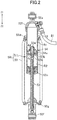
FIG. 2 is a cross-sectional view illustrating an example of a left suspension included in the suspension system; -
FIG. 3A is a front view illustrating an example of the intermediate unit; -
FIG. 3B is a plan view illustrating the example of the intermediate unit; -
FIG. 4A is a cross-sectional view taken along the line IV-IV illustrated inFIG. 3A ; -
FIG. 4B is an enlarged view of a part ofFIG. 4A ; -
FIG. 5 is a cross-sectional view taken along the line V-V illustrated inFIG. 3A ; -
FIG. 6A is a damping force characteristic diagram for explaining the responsiveness of the suspension system; -
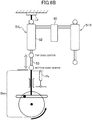
FIG. 6B is a diagram schematically illustrating a damping force tester for measuring a relationship between a speed and a force of a piston rod illustrated inFIG. 6A ; -
FIG. 7A is a diagram illustrating a change with time of a reaction force of the damper in the suspension system proposed in the present disclosure; -
FIG. 7B is a diagram illustrating a change with time of the reaction force of the damper in the suspension system in which the gas chamber and the oil chamber of the intermediate unit are partitioned by a free piston instead of a diaphragm; -
FIG. 8A is a diagram illustrating a relationship between a stroke of the piston rod and the reaction force of the damper in the suspension system proposed in the present disclosure; -
FIG. 8B is a diagram illustrating a relationship between the stroke of the piston rod and the reaction force of the damper in the suspension system in which the gas chamber and the oil chamber of the intermediate unit are partitioned by the free piston instead of the diaphragm; -
FIG. 9 is a cross-sectional view illustrating an example of the intermediate unit in which capacity of the gas chamber is variable; -
FIG. 10 is a cross-sectional view illustrating an example of the intermediate unit in which capacity of the oil chamber is variable; -
FIG. 11A is a schematic view illustrating an example of the intermediate unit having a bag-shaped partition member used as the diaphragm; -
FIG. 11B is a side view of the bag-shaped partition member illustrated inFIG. 11A ; -
FIG. 12 is a front view of a snowmobile which is an example of a vehicle equipped with the suspension system; and -
FIG. 13 is a schematic view of a four-wheeled vehicle which is an example of a vehicle equipped with the suspension system. - The terminology used herein is for the purpose of describing particular embodiments only and is not intended to be limiting of the present teaching. As used herein, the term "and/or" includes any and all combinations of one or more of the associated listed items. As used herein, the singular forms "a," "an," and "the" are intended to include the plural forms as well as the singular forms, unless the context clearly indicates otherwise. It will be further understood that the terms "comprises", "comprising", "includes", and/or "including", when used in this specification, specify the presence of stated features, steps, operations, elements, and/or components, but do not preclude the presence or addition of one or more other features, steps, operations, elements, components, and/or groups thereof.
- Unless otherwise defined, all terms (including technical and scientific terms) used herein have the same meaning as commonly understood by one having ordinary skill in the art to which this teaching belongs. It will be further understood that terms, such as those defined in commonly used dictionaries, should be interpreted as having a meaning that is consistent with their meaning in the context of the relevant art and the present disclosure and will not be interpreted in an idealized or overly formal sense unless expressly so defined herein.
- In describing the present teaching, it will be understood that a number of technologies are disclosed. Each of these has individual benefit and each can also be used in conjunction with one or more, or in some cases all, of the other disclosed technologies. Accordingly, for the sake of clarity, this description will refrain from repeating every possible combination of the individual technologies in an unnecessary fashion. Nevertheless, the specification and claims should be read with the understanding that such combinations are entirely within the scope of the present teaching and the claims.
- In the following description, for purposes of explanation, numerous specific details are set forth in order to provide a thorough understanding of the present teaching. It will be evident, however, to one skilled in the art that the present invention may be practiced without these specific details.
- The present disclosure is to be considered as an exemplification of the present teaching, and is not intended to limit the present teaching to the specific embodiments illustrated by the figures or description below.
- The present invention will now be described by referencing the appended figures representing embodiments. In this specification, a
suspension system 10 illustrated inFIG. 1 and the like will be described as an example of a suspension system proposed in the present disclosure. Thesuspension system 10 is mounted on vehicles such as snowmobiles and four-wheeled vehicles. The four-wheeled vehicle includes, for example, a passenger car, an All Terrain Vehicle (ATV), a Recreational Off-highway Vehicle (ROV), a golf cart, and the like. - In the following description, directions indicated by X1 and X2 in
FIG. 1 are referred to as right and left, respectively, and directions indicated by Z1 and Z2 inFIG. 1 are referred to as upper and lower, respectively. The directions indicated by Y1 and Y2 inFIG. 4A are referred to as front and rear, respectively. Note that these directions refer to illustration of the figures, does not indicate technical limitation of the present invention, and does not limit the position and the orientation of the suspension system in vehicles. - As illustrated in
FIG. 1 , thesuspension system 10 has twosuspensions suspensions dampers FIG. 2 ). Thesuspension 50R is disposed, for example, in the right direction of a vehicle body and buffers up and down movement of a right ski or a right wheel (in this specification, a member which is in contact with a snow surface or a road surface and supports the vehicle body, such as a ski and a wheel, is referred to as a vehicle body support member). Thesuspension 50L is disposed, for example, in the left direction of the vehicle body and buffers up and down movement of the left vehicle body support member. In the following description, thedamper 51R is referred to as "right damper" (first damper), and thedamper 51L is referred to as "left damper" (second damper). When thesuspension system 10 is mounted on a four-wheeled vehicle, one of the two suspensions may buffer the up and down movement of a front wheel and the other suspension may buffer the up and down movement of a rear wheel. - As illustrated in
FIG. 2 , theleft damper 51L includes acylinder 52 and apiston rod 53. Thecylinder 52 includes oil chambers R1 and R2 in which oil is filled. Thepiston rod 53 has, at its end, apiston 54 which partitions the oil chambers R1 and R2. Thepiston 54 and/or thepiston rod 53 include a damping force generating mechanism (71L) which generates a damping force when they move relative to thecylinder 52. Theright damper 51R has the same structure as theleft damper 51L. That is, theright damper 51R also includes acylinder 52, apiston rod 53, apiston 54, and the damping force generating mechanism (71R). Hereinafter, an example of the structure of thedampers left damper 51L illustrated inFIG. 2 . - As illustrated in
FIG. 2 , as an example of the damping force generating mechanism, thepiston 54 hasflow paths 54a and 54b which allow oil to move between the first oil chamber R1 and the second oil chamber R2 andvalve plates flow paths 54a and 54b. When the oil passes through theflow paths 54a and 54b, a damping force is generated. - As illustrated in
FIG. 2 , as an example of the damping force generating mechanism, thepiston rod 53 may includeflow paths flow paths flow paths cylinder 52. The needle valve 53e can move to a closed position in which the needle valve 53e is fitted to theflow path 53a to close theflow path 53a, an open position in which the needle valve 53e is away from theflow path 53a to open theflow path 53a, and a position between the closed position and the open position. Thedamper 51L has an operation unit (not illustrated) connected to the needle valve 53e. A user can adjust the position of the needle valve 53e (in other words, the degree of opening of theflow paths - As illustrated in
FIG. 2 , thecylinder 52 has acap 52c at its lower (first) end for closing thecylinder 52. Thepiston rod 53 extends from thepiston 54 through the second oil chamber R2 toward thecap 52c and protrudes from thecap 52c to the outside of thecylinder 52. - Vehicles such as snowmobiles and four-wheeled vehicles have arms which connect the vehicle body support member and the vehicle body frame so that the vehicle body support member (skis or wheels) can move up and down relative to the vehicle body frame. For example, an end portion (lower end) 53f of the
piston rod 53 is connected to this arm and an end portion (upper end) 52a of thecylinder 52 is connected to the vehicle body frame. Therefore, thepiston 54 and thepiston rod 53 move relative tocylinder 52 in accordance with the up and down movement of the vehicle body support member. - As illustrated in
FIG. 2 , aspring sheet 52d is attached to an outer peripheral surface of thecylinder 52 and aspring sheet 53g is attached to an end portion of thepiston rod 53. Thespring 59 is held between thespring sheet 52d and thespring sheet 53g. - As illustrated in
FIG. 1 , thesuspension system 10 includes anintermediate unit 60 arranged in oil flow paths ER and EL connecting the first oil chamber R1 of theright damper 51R and the first oil chamber R1 of theleft damper 51L. The left (second) oil flow path EL has a pipe 81 (seeFIG. 2 ) extending from theleft damper 51L. The right (first) oil flow path ER has thepipe 81 extending from theright damper 51R. The twopipes 81 are connected to theintermediate unit 60. - The
intermediate unit 60 includes an intermediate oil chamber T1 connected to the first oil chambers R1 of thedampers intermediate case 61 having therein an intermediate gas chamber T2. The intermediate gas chamber T2 is filled with, for example, a gas such as nitrogen or air. The intermediate oil chamber T1 and the intermediate gas chamber T2 are partitioned by a diaphragm 64 (seeFIG. 4A ) described below. The intermediate oil chamber T1 is connected to the first oil chamber R1 of theright damper 51R via the oil flow path ER and is connected to the first oil chamber R1 of theleft damper 51L via the oil flow path EL. (Hereinafter, the oil flow path ER is referred to as "right oil flow path" and the oil flow path EL is referred to as "left oil flow path"). The right oil flow path ER and the left oil flow path EL are configured of the pipes 81 (seeFIGS. 2 and3A ) formed of rubber or resin. A flow path to which thepipe 81 is connected is formed in acap 52f (seeFIG. 2 ) which closes the upper (second) end of thecylinder 52. - For example, when the right vehicle body support member and the left vehicle body support member ride on a bump on a snow surface or a road surface and thus the two
dampers dampers dampers left damper 51L is compressed due to the vehicle turning right, the twodampers left damper 51L to the intermediate oil chamber T1 and oil moves from the intermediate oil chamber T1 to theright damper 51R. As a result, theright damper 51R is extended and the contact pressure between the right vehicle body support member and the snow or road surface is secured. - As illustrated in
FIG. 4A , the intermediate oil chamber T1 and the intermediate gas chamber T2 are arranged in a direction along an axis (the axis of a cylindricalmain body 62 described below) Ax1 (first direction) of theintermediate case 61. In the exampledintermediate unit 60, the intermediate gas chamber T2 is formed below the intermediate oil chamber T1. Conversely, the intermediate oil chamber T1 may be formed below the intermediate gas chamber T2. The intermediate gas chamber T2 is partitioned from the intermediate oil chamber T1 by thediaphragm 64. - The position of an outer
peripheral edge 64a of thediaphragm 64 is fixed to theintermediate case 61. Thediaphragm 64 is formed of a flexible material. The term "flexible" means that the material can be curved or bent. Thediaphragm 64 may be stretchable or elastic owing to the flexibility. The material of thediaphragm 64 is, for example, rubber. Thediaphragm 64 may be formed of a resin which can be recessed, that is, has flexibility. When the oil flows into the intermediate oil chamber T1 from thedampers diaphragm 64 is deformed, specifically, thediaphragm 64 is recessed (see thediaphragm 64 illustrated by a two-dot chain line inFIG. 4A ), and thus the intermediate oil chamber T1 expands and the intermediate gas chamber T2 contracts. Conversely, when oil flows out from the intermediate oil chamber T1 to the oil chambers R1 of thedampers diaphragm 64 is deformed, and specifically, thediaphragm 64 is bulged to its original shape, and thus the intermediate oil chamber T1 contracts and the intermediate gas chamber T2 expands. - In the structure in which the intermediate gas chamber T2 and the intermediate oil chamber T1 are partitioned by a free piston movable in the intermediate case, instead of the
flexible diaphragm 64, when the free piston moves in theintermediate case 61, a small amount of friction occurs between the free piston and the inner surface of theintermediate case 61. On the other hand, in the structure proposed in the present disclosure, since the intermediate gas chamber T2 and the intermediate oil chamber T1 are partitioned by theflexible diaphragm 64, that friction does not occur. Therefore, the capacity change of the intermediate oil chamber T1 and the intermediate gas chamber T2 is made smoother than in the structure having the free piston, and thus the responsiveness of thesuspension system 10 can be improved. - As illustrated in
FIG. 4A , thediaphragm 64 bulges from the outer peripheral edge (lower edge) 64a toward the intermediate oil chamber T1. Thediaphragm 64 is bulged in a direction (upward in the example described here) along the axis Ax1 of theintermediate case 61 and has a bag shape having the intermediate gas chamber T2 inside. Thediaphragm 64 includes abody portion 64b of a cylindrical shape and atop portion 64c of a hemispherical shape located at an end portion of thebody portion 64b. According to this shape of thediaphragm 64, when the oil flows into the intermediate oil chamber T1, for example, thebody portion 64b is recessed (see the diagram 64 illustrated by a two-dot chain line inFIG. 4A ). Therefore, the expansion of the intermediate oil chamber T1 and the contraction of the intermediate gas chamber T2 can be smoothly generated. - As illustrated in
FIG. 4A , theintermediate case 61 includes the cylindricalmain body 62 having an open lower end portion and alid member 63 for closing the lower end portion. The cylindricalmain body 62 may have a cylindrical shape having a circular or elliptical cross section or a cylindrical shape having a square cross section. The inner surface of thelid member 63 faces the intermediate gas chamber T2 and the intermediate gas chamber T2 is sealed by thelid member 63 and thediaphragm 64. Thelid member 63 includes an annular or cylindrical lid outerperipheral portion 63A and a lidcentral portion 63B fitted inside the lid outerperipheral portion 63A. According to this structure, for example, the capacity of the intermediate gas chamber T2 can be adjusted by moving the lidcentral portion 63B in the direction along the axis Ax1 with respect to the lid outerperipheral portion 63A. The movement of the lidcentral portion 63B can be performed by inserting a tool into a gaspressure adjusting hole 63h formed in the lidcentral portion 63B. Theintermediate case 61 may not have such a gas volume adjusting mechanism. In this case, the material of the lid outerperipheral portion 63A and the material of the lidcentral portion 63B may be different from each other or may be the same. - As illustrated in
FIG. 4A , the outerperipheral edge 64a of thediaphragm 64 is fixed to theintermediate case 61 by being interposed between thelid member 63 and the cylindricalmain body 62. The outerperipheral edge 64a of thediaphragm 64 is pressed by the lid member 63 (more specifically, the lid outerperipheral portion 63A) and is in close contact with the cylindricalmain body 62. With this structure, the work of attaching thediaphragm 64 can be simplified and the sealing of the intermediate gas chamber T2 and the intermediate oil chamber T1 can be ensured. - The
lid member 63 is fitted inside the cylindricalmain body 62. The outerperipheral edge 64a of thediaphragm 64 is interposed between the outer peripheral surface of thelid member 63 and the inner surface of the cylindricalmain body 62. More specifically, the outerperipheral edge 64a of thediaphragm 64 is interposed between the outer peripheral surface of the lid outerperipheral portion 63A and the inner surface of the cylindricalmain body 62. - The outer
peripheral edge 64a of thediaphragm 64 may be hooked on the outer peripheral surface of thelid member 63. Specifically, as illustrated inFIG. 4B , the outerperipheral edge 64a may have an engaging portion 64d. The engaging portion 64d is a convex portion protruding toward the inside of the cylindricalmain body 62. An engagedportion 63a, which is a groove extending in the circumferential direction, is formed on the outer peripheral surface of the lid outerperipheral portion 63A. The engaging portion 64d is hooked on the engagedportion 63a. Contrary to the example in theintermediate unit 60, a groove extending in the circumferential direction may be formed as an engaging portion on the inner surface of the outerperipheral edge 64a of thediaphragm 64 and a convex portion fitted into this groove may be formed as an engaged portion on the outer peripheral surface of the lid outerperipheral portion 63A. - As illustrated in
FIG. 4B , anannular stopper member 63e which defines the position of the lid outerperipheral portion 63A may be attached to the inner surface of the cylindricalmain body 62. Thestopper member 63e is located below (outer side in the direction along the axis Ax1) the lid outerperipheral portion 63A and is held by a groove formed on the inner surface of the cylindricalmain body 62. The downward movement (outward movement in the direction along the axis Ax1) of the lid outerperipheral portion 63A may be regulated by thestopper member 63e and the position of the lid outerperipheral portion 63A may be fixed by thestopper member 63e. - According to this structure, the work of attaching the
diaphragm 64 to theintermediate case 61 can be further simplified. For example, in the work of attaching thediaphragm 64, the outerperipheral edge 64a of thediaphragm 64 is hooked on the outer peripheral surface of the lid outerperipheral portion 63A, and then the lid outerperipheral portion 63A is fitted inside the cylindricalmain body 62. Then, thestopper member 63e is attached to the inner surface of the cylindricalmain body 62. Next, when the lid outerperipheral portion 63A is lowered, the lid outerperipheral portion 63A is caught by thestopper member 63e and the position of the lid outerperipheral portion 63A is fixed together with thediaphragm 64. Finally, the lidcentral portion 63B is fitted inside the lid outerperipheral portion 63A. As a result, the lid outerperipheral portion 63A is pressed against the inner surface of the cylindricalmain body 62 together with the outerperipheral edge 64a of thediaphragm 64. Anannular stopper member 63d is fitted on the inner surface of the lid outerperipheral portion 63A. A groove is formed on the inner surface of the lid outerperipheral portion 63A and thestopper member 63d is arranged in this groove. The position of the lidcentral portion 63B is defined by thestopper member 63d. - As illustrated in
FIG. 4B , astep 62a bulging inward is formed on the inner surface of the cylindricalmain body 62. When the lid outerperipheral portion 63A is fitted inside the cylindricalmain body 62 in the work of attaching thediaphragm 64 and the lid outerperipheral portion 63A, thestep 62a functions as a stopper which prevents the lid outerperipheral portion 63A from excessively entering the inside. - As illustrated in
FIG. 4B , the position of the lidcentral portion 63B is higher than an end portion (lower end) 64e of thediaphragm 64. That is, the position of the lidcentral portion 63B is closer to the center of the cylindricalmain body 62 in the direction along the axis Ax1 than the position of theend portion 64e of thediaphragm 64. - An
annular sealing member 63c is provided between the inner surface of the lid outerperipheral portion 63A and the outer peripheral surface of the lidcentral portion 63B. In the exampledintermediate unit 60, the position of the sealingmember 63c attached to the outer peripheral surface of the lidcentral portion 63B is also higher than that of the end portion (lower end) 64e of thediaphragm 64. Therefore, the sealingmember 63c is located radially inward of the outerperipheral edge 64a of thediaphragm 64. - As illustrated in
FIG. 4A , the gaspressure adjusting hole 63h is formed in the lidcentral portion 63B, which allows gas to be injected into the intermediate gas chamber T2 and discharge of gas from the intermediate gas chamber T2. The gaspressure adjusting hole 63h has avalve 63f, which is, for example, a rubber valve. By inserting a gas injection needle into the gaspressure adjusting hole 63h and a hole formed in the rubber valve, gas injection and gas discharge can be performed. Thelid member 63 may have acover 63C which covers the gaspressure adjusting hole 63h. - The structure of the
intermediate case 61 is not limited to the example described here. For example, the lid outerperipheral portion 63A and the lidcentral portion 63B may be formed integrally. That is, the lid outerperipheral portion 63A and the lidcentral portion 63B may be one member integrally formed of metal or resin. Further, a screw and a screw groove are formed on the outer peripheral surface of the lid outerperipheral portion 63A and the inner surface of the cylindricalmain body 62, respectively, and the screw and the screw groove may allow the lid outerperipheral portion 63A to be fixed to the cylindricalmain body 62. Also in this case, the outerperipheral edge 64a of thediaphragm 64 may be attached to the outer peripheral surface of the cylindricalmain body 62. In this case, thestopper member 63e may not be used for attaching the lid outerperipheral portion 63A to the cylindricalmain body 62. - When the left and
right dampers piston rod 53 enters thecylinder 52. When theright damper 51R is in the most compressed state (minimum length), a part of thepiston rod 53 is located within the second oil chamber R2 (seeFIG. 2 ). The volume of the part of thepiston rod 53 is defined as "V1". Similarly, when theleft damper 51L is in the most compressed state (minimum length), a part of thepiston rod 53 is located within the second oil chamber R2. The volume of the part of thepiston rod 53 is defined as "V2". When V1 and V2 are defined in this way, the capacity of the intermediate gas chamber T2 when the left andright dampers piston 54 can be smoothed. In the exampledintermediate unit 60, the volume of thediaphragm 64, which formed in a bag shape as described above, is greater than V1 + V2. The volume ofdiaphragm 64 may be greater than twice V1 + V2. - In the above description, the "most compressed state of the
dampers piston 54 or a member thereof which moves integrally with thepiston 54 collides with any part of thecylinder 52 and thus the movement of thepiston 54 in a compression direction is restricted. The most compressed state of thedampers spring sheet 53g hits thecap 52c of thecylinder 52. On the other hand, the "most extended state of thedampers piston 54 or a member which moves integrally with thepiston 54 collides with any part of thecylinder 52 and the movement of thepiston 54 in an extension direction is restricted. For example, the most extended state of thedampers piston 54 collides with the lower end of thecylinder 52. - As described above, when oil flows into the intermediate oil chamber T1 from the left and
right dampers FIG. 4A , thediaphragm 64 is bent (recessed). Therefore, the intermediate oil chamber T1 expands and the intermediate gas chamber T2 contracts. Thediaphragm 64 has a sufficient area so that such deflection occurs. Specifically, the surface area of thediaphragm 64 is larger than the sum of the cross-sectional areas inside thecylinders 52 of the left andright dampers cylinders 52 in the cross-section thereof taken along a plane vertical to the axial direction of thecylinder 52. The surface area of thediaphragm 64 is the sum of the surface area of thecylindrical body portion 64b and the surface area of the hemisphericaltop portion 64c. The area of thebody portion 64b may be larger than the sum of the cross-sectional areas inside thecylinders 52 of the left andright dampers diaphragm 64 may be larger than twice the sum of the cross-sectional areas inside thecylinders 52 of the left andright dampers - The size (length L2, see
FIG. 4A ) of thediaphragm 64 in the direction along the axis Ax1 is larger than half the size (length L1, seeFIG. 4A ) of the cylindricalmain body 62 in the same direction. This facilitates securing the surface area of thediaphragm 64. In the exampledintermediate unit 60, the diameter of the inner surface of the cylindricalmain body 62 is larger than the diameter of the inner surface of thecylinder 52 of thedamper diaphragm 64. - The
intermediate unit 60 has a valve assembly 70 (seeFIG. 3A ). Thevalve assembly 70 is attached to an upper end portion (end portion opposite to the lid member 63) of the cylindricalmain body 62 and closes the cylindricalmain body 62. As illustrated inFIG. 5 , thevalve assembly 70 includes a (first) dampingforce generating mechanism 71R located on the way of an oil flow path ER1 connecting thecylinder 52 of theright damper 51R and the intermediate oil chamber T1 and a (second) damping force generating mechanism 71L located on the way of an oil flow path EL1 connecting thecylinder 52 of theleft damper 51L and the intermediate oil chamber T1. Ahousing 79 of thevalve assembly 70 is formed with aflow path 79a (seeFIG. 4A ) connecting the right dampingforce generating mechanism 71R and the intermediate oil chamber T1 and theflow path 79a connecting the left damping force generating mechanism 71L and the intermediate oil chamber T1. Theflow path 79a extends in a direction (up-down direction) along the axis Ax1. Thevalve assembly 70 has a switchingvalve 72. Details of the dampingforce generating mechanisms 71R and 71L and the switchingvalve 72 will be described below. - The damping
force generating mechanisms 71R and 71L are located in a direction (more specifically, upward) along the axis Ax1 with respect to thediaphragm 64. Thediaphragm 64 has a bag shape which bulges from the outerperipheral edge 64a toward the dampingforce generating mechanisms 71R and 71L. As illustrated inFIG. 5 , when theintermediate unit 60 is viewed in the direction along the axis Ax1, the twoflow paths 79a (seeFIGS. 5 and4A ) connecting the dampingforce generating mechanisms 71R and 71L and the intermediate oil chamber T1 are located inside the outerperipheral edge 64a of thediaphragm 64. When theintermediate unit 60 is viewed in the direction along the axis Ax1, flowpath members 71c of the dampingforce generating mechanisms 71R and 71L are located inside the outerperipheral edge 64a of thediaphragm 64. Further, when theintermediate unit 60 is viewed in the direction along the axis Ax1, the switchingvalve 72 is also located inside the outerperipheral edge 64a of thediaphragm 64. As described above, the plurality of dampingforce generating mechanisms 71R and 71L and thevalve 72 are arranged in a small area, and thus the size of theintermediate unit 60 is reduced. - As illustrated in
FIG. 5 , when theintermediate unit 60 is viewed in the direction along the axis Ax1, the dampingforce generating mechanisms 71R and 71L are arranged at positions symmetrical with respect to a vertical plane Pv passing through the center of thediaphragm 64. Therefore, theflow paths 79a connecting the dampingforce generating mechanisms 71R and 71L and the intermediate oil chamber T1 are also formed at positions symmetrical with respect to the vertical plane Pv. -
FIG. 6A is a graph illustrating a damping force characteristic diagram for explaining the responsiveness of thesuspension system 10.FIG. 6B is a schematic diagram illustrating a damping force tester for measuring a relationship between a speed and a force of a piston rod illustrated inFIG. 6A . - As illustrated in
FIG. 6B , the lower end of thepiston rod 53 of one of the right and leftdampers piston rod 53 is moved up and down by the drive mechanism Dm. For example, theleft damper 51L is connected to the driving mechanism Dm. The upper end of thecylinder 52 of theleft damper 51L is attached to a load sensor Ld. The resistance (that is, the damping force) generated by the left damper 51 is measured based on the output of the load sensor Ld. Thepiston rod 53 of theleft damper 51L is connected to a position sensor Ps. The speed of thepiston rod 53 is calculated based on the output of the position sensor Ps. As the position sensor Ps, for example, a linear variable operation transformer can be used. The other damper (theright damper 51R inFIG. 6B ) is arranged so that thepiston rod 53 can be freely displaced. - In
FIG. 6A , the horizontal axis is the speed (that is, the speed of the piston 54) of thepiston rod 53 calculated based on the output of the position sensor Ps and the vertical axis is the force (that is, the damping force exerted by the damper) calculated from the output of the load sensor Ld. In these figures, each quadrant represents the following state.
(First quadrant) Speed: Speed at rebound (extension), Force: Damping force in the direction opposing rebound;
(Second quadrant) Speed: Speed at bump (compression), Force: Damping force in the direction opposing rebound;
(Third quadrant) Speed: Speed at bump, Force: Damping force in the direction opposing bump;
(Fourth quadrant) Speed: Speed at rebound, Force: Damping force in the direction opposing bump.
InFIG. 6 , a point P1 corresponds to the top dead center of thepiston rod 53 and a point P2 corresponds to the bottom dead center of thepiston rod 53. - As illustrated in
FIG. 6A , the direction of the force generated by the damper 51 is reversed slightly after thepiston rod 53 reaches the top dead center P1. In the illustrated example, when the speed of thepiston rod 53 reaches S1, the direction of the force generated by the damper 51 is reversed. The direction of the force generated by the damper 51 is reversed slightly after thepiston rod 53 reaches the bottom dead center P2. In the illustrated example, when the speed of thepiston rod 53 reaches S2, the direction of the force generated by the damper 51 is reversed. No friction occurs when thediaphragm 64 moves. Therefore, the responsiveness of thesuspension system 10 can be improved as compared with the suspension system in which the intermediate oil chamber T1 and the intermediate gas chamber T2 are partitioned by a free piston instead of thediaphragm 64. That is, the speeds S1 and S2 approach 0. -
FIG. 7A is a schematic diagram illustrating a change with time of a reaction force acting on thepiston rod 53 due to the compression of the intermediate gas chamber T2 in thesuspension system 10.FIG. 7B is a schematic diagram illustrating a change with time of the reaction force acting on thepiston rod 53 due to the compression of the intermediate gas chamber T2 in the suspension system in which the intermediate oil chamber T1 and the intermediate gas chamber T2 are partitioned by a free piston instead of thediaphragm 64. In the suspension system in which the intermediate oil chamber T1 and the intermediate gas chamber T2 are partitioned by the free piston, a small amount of friction may occur between the free piston and the inner surface of theintermediate case 61. Therefore, as illustrated inFIG. 7B , even when the reaction force gradually increases, the reaction force changes stepwise in a very short period. It is estimated that the state where the free piston does not move due to friction occurs several times in one stroke. On the other hand, in thesuspension system 10 having theflexible diaphragm 64, there is no such friction, so that the reaction force changes smoothly as illustrated inFIG. 7A . - When the
dampers piston rod 53 enters thecylinder 52, so that the oil moves to the intermediate oil chamber T1 and the intermediate gas chamber T2 is compressed.FIG. 8A is a diagram schematically illustrating the relationship between the stroke (displacement in the compression direction) of thepiston rod 53 and the reaction force acting on thepiston rod 53 due to the compression of the intermediate gas chamber T2 in thesuspension system 10.FIG. 8B is a diagram schematically illustrating the relationship between the stroke of thepiston rod 53 and the reaction force acting on thepiston rod 53 due to compression of the intermediate gas chamber T2 in the suspension system in which the intermediate oil chamber T1 and the intermediate gas chamber T2 are partitioned by a free piston instead of thediaphragm 64. - As illustrated in
FIG. 8B , in a suspension system using a free piston, the pressure of the intermediate gas chamber T2 increases as the stroke of thepiston rod 53 increases, so that the reaction force acting on thepiston rod 53 gradually increases. - On the other hand, since the
diaphragm 64 of thesuspension system 10 is made of rubber, the thickness of thediaphragm 64 decreases as the pressure acting on thediaphragm 64 increases. Therefore, even when the stroke of thepiston rod 53 increases from 0 and the pressure of the intermediate oil chamber T1 increases, the thickness of thediaphragm 64 decreases, so that compression of the intermediate gas chamber T2 hardly occurs. Therefore, as illustrated inFIG. 8A , in a range where the stroke of thepiston rod 53 is small, the increase in the reaction force acting on thepiston rod 53 is slow. Then, when the stroke of thepiston rod 53 further increases, the pressure of the intermediate oil chamber T1 increases, and accordingly, the reaction force acting on thepiston rod 53 also increases. However, since the pressure rise in the intermediate oil chamber T1 is partially absorbed by the decrease in the thickness of thediaphragm 64, the increase in the reaction force acting on thepiston rod 53 is slower than that in the suspension system using a free piston. Since thediaphragm 64 has a bag shape and the area of thediaphragm 64 is larger than the area (the cross-sectional area of the intermediate case 61) of the free piston, the influence of the decrease in the thickness of thediaphragm 64 is large. - As illustrated in
Fig. 5 , the dampingforce generating mechanism 71R is located on the way of the right oil flow path ER and generates resistance to oil movement between theright damper 51R and the intermediate oil chamber T1. The damping force generating mechanism 71L is located on the way of the left oil flow path EL and generates resistance to oil movement between theleft damper 51L and the intermediate oil chamber T1. The resistance due to the dampingforce generating mechanisms 71R and 71L becomes a damping force with respect to the up and down movement of the vehicle body supporting members such as skis and wheels. - As illustrated in
FIG. 5 , the dampingforce generating mechanisms 71R and 71L are held by, for example, thehousing 79. In thehousing 79, the flow paths ER1 and EL1 from connection ports ER2 and EL2 to the dampingforce generating mechanisms 71 R and 71L are formed.Nipples 81a (seeFIG. 3A ) provided at the end portions of thepipe 81 are connected to the connection ports ER2 and EL2. - As illustrated in
FIG. 5 , each of the dampingforce generating mechanisms 71R and 71L has afirst flow path 71e and aflow path member 71c in which a plurality ofsecond flow paths 71f are formed. An oil chamber connected to the intermediate oil chamber T1 is formed in thehousing 79. Theflow path member 71c is arranged in the oil chamber. Each of the dampingforce generating mechanisms 71R and 71L has a rotatablemovable portion 71a. Themovable portion 71a has aneedle valve 71h which can be inserted into thefirst flow path 71e. The degree of opening of thefirst flow path 71e is determined according to the rotational position of themovable portion 71a. Outside thevalve assembly 70,valve operation portions movable portions 71a are attached. A user can respectively adjust the degrees of opening of thefirst flow paths 71e by operating thevalve operation portions second flow path 71f of theflow path member 71c,valve plates 71i and 71j for limiting the amount of oil flowing through thesecond flow path 71f are provided. - The structure of the damping
force generating mechanisms 71R and 71L is not limited to the example described here. For example, the dampingforce generating mechanisms 71R and 71L may not be provided with theneedle valve 71h or thevalve plates 71i and 71j. In this case, a small hole (orifice) for generating a damping force may be formed in theflow path member 71c. - The
suspension system 10 may have a bypass flow path E1 (seeFIG. 1 ) which connects the right oil flow path ER and the left oil flow path EL. The bypass flow path E1 connects the right oil flow path ER and the left oil flow path EL without passing through the intermediate oil chamber T1 and the dampingforce generating mechanisms 71R and 71L. The bypass flow path E1 is formed in thehousing 79 and connects the right and left flow paths ER1 and EL1 (seeFIG. 5 ) also formed in thehousing 79. - As illustrated in
FIG. 1 , the switchingvalve 72 may be provided in the bypass flow path E1. The switchingvalve 72 allows oil to flow through the bypass flow path E1 or restricts oil from flowing through the bypass flow path E1. When the switchingvalve 72 is in the open state, the oil moves between theright damper 51R and theleft damper 51L without passing through the intermediate oil chamber T1 and the dampingforce generating mechanisms 71R and 71L. - As illustrated in
FIG. 5 , a switchingflow path 72a for connecting the right oil flow path ER and the left oil flow path EL is formed in the switchingvalve 72, for example. The switchingvalve 72 can move to a position (connection position) connecting the right oil flow path ER and the left oil flow path EL through the switchingflow path 72a and a position (blocking position) blocking the right oil flow path ER and the left oil flow path EL. The switchingvalve 72 is configured to be rotatable between the connection position and the blocking position. - In the switching
valve 72, a plurality of switching flow paths having different flow path cross sections (thickness of the flow path) may be formed. That is, a plurality of switching flow paths having different resistances to the flow of oil may be formed in the switchingvalve 72. Further, the movement of the switchingvalve 72 may be sliding along a straight line instead of rotating. As illustrated inFIGS. 3A and 3B , the switchingvalve 72 has avalve operation portion 72N. Thevalve operation portion 72N is rotatable integrally with the switchingvalve 72. - As the vehicle turns, oil moves from the outer damper to the inner damper via the oil flow path. For example, when the vehicle turns right, oil moves from the
left damper 51L to theright damper 51R. When the vehicle turns right in a state where the switchingvalve 72 is located at the connection position, most of the oil moves from theleft damper 51L to theright damper 51R via the bypass flow path E1 without passing through the intermediate oil chamber T1 and the dampingforce generating mechanisms 71R and 71L.Therefore, theleft damper 51L contracts smoothly and theright damper 51R extends smoothly. As a result, the contact pressure between the right vehicle body support member and the snow or road surface can be improved. When the switchingvalve 72 is located at the blocking position, no oil moves via the bypass flow path E1. Therefore, when the vehicle turns right, all the oil moving from theleft damper 51L to theright damper 51R passes through the dampingforce generating mechanisms 71R and 71L, so that a greater damping force can be obtained. - When the
right damper 51R and theleft damper 51L contract at the same time, for example, when the right body support member and the left body support member simultaneously ride on a bump on a snow surface or a road surface, regardless of the position of the switchingvalve 72, all oil flowing from theright damper 51R to the intermediate oil chamber T1 passes through the dampingforce generating mechanism 71R and all oil flowing from theleft damper 51L to the intermediate oil chamber T1 passes through the damping force generating mechanism 71L. Therefore, a large damping force can be obtained. In this case, the intermediate oil chamber T1 of theintermediate unit 60 expands and thediaphragm 64 is largely recessed. - The
intermediate unit 60 may be configured so that the capacity of the intermediate gas chamber T2 can be changed.FIG. 9 illustrates theintermediate unit 60 having such a structure. InFIG. 9 , the same members and parts as those illustrated inFIG. 4A and the like are denoted by the same reference numerals and letters. Matters not described in the structure illustrated inFIG. 9 may be the same as those illustrated inFIG. 4A and the like. - The
intermediate unit 60 illustrated inFIG. 9 has alid member 163 having a lid outerperipheral portion 163A and the lidcentral portion 63B fitted inside the lid outerperipheral portion 163A. The size of the lid outerperipheral portion 163A in the direction along the axis Ax1 is larger than that of the lid outerperipheral portion 63A illustrated inFIG. 4A and the like. In addition, the position of the lidcentral portion 63B in the lid outerperipheral portion 163A can be changed in the direction along axis Ax1. For example, a plurality ofgrooves 63g for fitting thestopper member 63d which defines the position of the lidcentral portion 63B are formed on the inner surface of the lid outerperipheral portion 163A. The plurality ofgrooves 63g are arranged at intervals in the direction along the axis Ax1. The position (in other words, the capacity of the intermediate gas chamber T2) of the lidcentral portion 63B can be changed stepwise by changing thegroove 63g in which thestopper member 63d is arranged. - In the example illustrated in
FIG. 9 , the position of the lidcentral portion 63B can be set not only at a position (the position of the lidcentral portion 63B indicated by the two-dot chain line) defined inside the cylindricalmain body 62 but also at a position (the position defined below the lower end of cylindricalmain body 62, position of the lidcentral portion 63B indicated by the solid line) defined outside the cylindricalmain body 62. - When the capacity of the intermediate gas chamber T2 is variable, the pressure in the intermediate gas chamber T2 can be optimized. For example, when the capacity of the intermediate gas chamber T2 is reduced, the pressure in the intermediate gas chamber T2 in the most compressed state of the damper increases. (Here, the "most compressed state" is where the
piston rod 53 is pushed into thecylinder 52 the largest, in other words, a state in which the length of the damper is minimized.) Conversely, increasing the capacity of the intermediate gas chamber T2 reduces the pressure in the intermediate gas chamber T2 in the most compressed state of the damper. The pressure in the intermediate gas chamber T2 affects the movement of thediaphragm 64. For example, when the capacity of the intermediate gas chamber T2 is reduced and the pressure in the intermediate gas chamber T2 in the most compressed state is increased, the deflection (deformation) of thediaphragm 64 as shown by the two-dot chain line inFIG. 4A becomes small. The deflection of thediaphragm 64 affects the responsiveness of thesuspension system 10. Therefore, by changing the capacity of the intermediate gas chamber T2, a pressure optimized for the responsiveness of thesuspension system 10 can be secured in the intermediate gas chamber T2. - Further, when there are a plurality of dampers having different sizes, it is also possible to secure an optimal capacity for the size (the size and the movable range of the piston rod 53) of the selected
dampers - The
intermediate unit 60 may be configured such that the capacity of the intermediate oil chamber T1 can be changed.FIG. 10 illustrates anintermediate unit 60 having such a structure. InFIG. 10 , the same members and parts as those illustrated inFIGS. 4A and9 , and the like are denoted by the same reference numerals and letters. Matters not described in the structure illustrated inFIG. 10 may be the same as those illustrated inFIGS. 4A and9 , and the like. - The
intermediate unit 60 illustrated inFIG. 10 has a cylindricalmain body 162 and alid member 163. The position of thelid member 163 in the cylindricalmain body 162 can be changed in the direction along the axis Ax1. More specifically, the position of a lid outerperipheral portion 163A in the cylindricalmain body 162 can be changed in the direction along the axis Ax1. The outerperipheral edge 64a of thediaphragm 64 is caught by the engagedportion 63a of the lid outerperipheral portion 163A as in theintermediate unit 60 illustrated inFIG. 4A and the like. Therefore, the position of the outerperipheral edge 64a of thediaphragm 64 changes as the position of the lid outerperipheral portion 163A changes, whereby the capacity of the intermediate oil chamber T1 can be increased or decreased. According to this structure, when there are a plurality of dampers having different sizes, an optimal capacity for the size (the size and the movable range of the piston rod 53) of the selecteddampers - As described above, the position of the lid outer
peripheral portion 163A is defined by thestopper member 63e. A plurality ofgrooves 162d for fitting thestopper member 63e are formed on the inner surface of the cylindricalmain body 162. The plurality ofgrooves 162d are arranged at intervals in the direction along the axis Ax1. The position (in other words, the capacity of the intermediate oil chamber T1) of the lid outerperipheral portion 163A in the direction along the axis Ax1 can be increased or decreased stepwise by changing thegroove 162d in which thestopper member 63e is arranged. - In the
intermediate unit 60 described above, the intermediate gas chamber T2 is configured by thelid member 63 and thediaphragm 64. However, the intermediate gas chamber T2 may be configured by a partition member formed in a bag shape by the diaphragm. In the example illustrated inFIGS. 11A and11B , theintermediate unit 60 has apartition member 264 formed in a bag shape. Thepartition member 264 has, for example, twodiaphragms 264a formed of a flexible material. The edges of thediaphragms 264a are attached to each other and have the intermediate gas chamber T2 inside. Thepartition member 264 may be floating in the intermediate oil chamber T1 or a part of the outer surface of thepartition member 264 may be fixed to the cylindricalmain body 62 or the like. The material of thediaphragm 264a may be formed of, for example, polyvinyl chloride, polyethylene, polypropylene, or the like. Thediaphragm 264a may be formed of rubber. In addition, thepartition member 264 does not necessarily need to be configured by a plurality ofdiaphragms 264a. That is, the bag-shapedpartition member 264 may be formed of one piece of thediaphragm 264a integrally formed of a material having flexibility. In such a structure, a cylindricalmain body 262 may have alid portion 263 instead of thelid member 63 and may be formed integrally with thelid portion 263. The material of the cylindricalmain body 262 may be metal or plastic. -
FIG. 12 is a diagram illustrating an example of a vehicle on which thesuspension system 10 is mounted. Asnowmobile 1 is illustrated as an example of the vehicle.FIG. 12 is a front view of thesnowmobile 1. - The
snowmobile 1 has aright ski 41R (vehicle body support member) for supporting a vehicle body and aleft ski 41L (vehicle body support member) for supporting the vehicle body. Theright ski 41R is supported by alower arm 42R and anupper arm 43R. Similarly, theleft ski 41L is supported by alower arm 42L and anupper arm 43L. Theright arms knuckle 44. Theright ski 41R is connected to the lower end of theknuckle 44. Theleft arms knuckle 44 to which theleft ski 41L is connected. This allows theskis - In the
exampled snowmobile 1, thedampers cylinder 52 is located at the upper part thereof and thepiston rod 53 is located at the lower part thereof. The upper ends 52a of thecylinders 52 of thedampers lower end 53f of thepiston rod 53 of theright damper 51R is connected to thelower arm 42R. Similarly, thelower end 53f of thepiston rod 53 of theleft damper 51L is connected to thelower arm 42L. As described above, thesprings 59 are provided in thedampers intermediate unit 60 is arranged, for example, above afront cover 9 which covers an upper side of a front part of the vehicle body. Thevalve operation portions FIG. 3A ) are located outside thecover 9. The layout of theintermediate unit 60 is not limited to the example of thesnowmobile 1. For example, theintermediate unit 60 may be disposed inside thecover 9 and thevalve operation portions - The
suspension system 10 may be mounted on a four-wheeled vehicle.FIG. 13 is a diagram illustrating an example of a four-wheeled vehicle 200 equipped with thesuspension system 10. The four-wheeled vehicle 200 is, for example, an ATV or an ROV. - The
automobile 200 has fourwheels automobile 200 hasarms wheels automobile 200, asuspension system 10 is applied to the right and leftfront wheels suspension system 10 is applied to the right and leftrear wheels cylinder 52 in the example ofFIG. 13 ) of theright damper 51R of thefront suspension system 10 is connected to thearm 211R which supports thefront wheel 202R and the lower end of theleft damper 51L is connected to thearm 211L which supports thefront wheel 202L. Similarly, the lower end (the end portion of thecylinder 52 in the example ofFIG. 13 ) of theright damper 51R of therear suspension system 10 is connected to thearm 212R which supports therear wheel 203R and the lower end of theleft damper 51L is connected to thearm 212L which supports therear wheel 203L. - The automobile on which the
suspension system 10 is mounted is not limited to the exampledautomobile 200 illustrated inFIG. 13 . For example, asuspension system 10 may be applied to the rightfront wheel 202R and the rightrear wheel 203R, and anothersuspension system 10 may be applied to the leftfront wheel 202L and the leftrear wheel 203L. As yet another example, asuspension system 10 may be applied to the rightfront wheel 202R and the leftrear wheel 203L and another suspension system may be applied to the leftfront wheel 202L and the rightrear wheel 203R. -
- (1) The
suspension system 10 includes theright damper 51R having thecylinder 52 in which the oil chambers R1 and R2 are formed, theleft damper 51L having thecylinder 52 in which the oil chambers R1 and R2 are formed, and theintermediate unit 60. Theintermediate unit 60 includes theintermediate case 61 having the intermediate oil chamber T1 connected to the oil chamber R1 of theright damper 51R and the oil chamber R1 of theleft damper 51L and the intermediate gas chamber T2. Theintermediate unit 60 includes thediaphragm 64 formed of a flexible material which partitions the intermediate oil chamber T1 and the intermediate gas chamber T2. In thissuspension system 10, unlike a system in which a free piston is used, when one of the intermediate oil chamber T1 and the intermediate gas chamber T2 expands and the other contracts due to the compression/expansion of thedampers intermediate unit 60 can be suppressed. - (2) The
diaphragm 64 is formed of rubber. According to this, the cost of theintermediate unit 60 can be reduced. - (3) The
diaphragm 64 has the outerperipheral edge 64a of which the position in theintermediate case 61 is fixed. Thediaphragm 64 has a shape bulging from the outerperipheral edge 64a toward the intermediate oil chamber T1. According to this shape of thediaphragm 64, the surface area of thediaphragm 64 is increased, so that the deflection of thediaphragm 64 can smoothly occur. As a result, when thedampers - (4) The
intermediate case 61 has the cylindricalmain body 62 having an open end portion and thelid member 63 for closing the end portion of the cylindricalmain body 62. Thediaphragm 64 has an outer peripheral edge of which the position in theintermediate case 61 is fixed. The outerperipheral edge 64a is attached to the cylindricalmain body 62 by thelid member 63. According to this structure, the work of attaching thediaphragm 64 to the intermediate unit can be simplified. - (5) The
lid member 63 includes the annular lid outerperipheral portion 63A, the lidcentral portion 63B fitted inside the lid outerperipheral portion 63A, and the sealingmember 63c located between the lid outerperipheral portion 63A and the lidcentral portion 63B. The sealingmember 63c is located inside the outerperipheral edge 64a. - (6) In the
lid member 63, the gaspressure adjusting hole 63h, which is a hole that allows gas to be injected into and discharged from the intermediate gas chamber T2, is formed. According to this structure, the operation of optimizing the gas pressure in the intermediate gas chamber T2 can be facilitated. - (7) The
intermediate unit 60 includes the dampingforce generating mechanism 71R located on the right oil flow path ER which is the flow path between the intermediate oil chamber T1 and the oil chamber R1 of theright damper 51R and the damping force generating mechanism 71L located on the left oil flow path EL which is the flow path between the intermediate oil chamber T1 and the oil chamber R1 of theleft damper 51L. According to this structure, the damping force can be optimized according to the driving situation. For example, the balance between the damping force obtained when the vehicle body rolls and the damping force obtained when the vehicle body pitches can be optimized as compared to a structure in which the damping force generating mechanism is provided only in thedampers - (8) The
intermediate unit 60 includes the bypass flow path E1 connecting the right oil flow path ER and the left oil flow path EL without passing through the dampingforce generating mechanism 71R and the damping force generating mechanism 71L and the switchingvalve 72 for opening or closing the bypass flow path E1. According to this structure, the movement of oil between the twodampers - (9) The damping
force generating mechanism 71R and the damping force generating mechanism 71L are fixed to one end portion of theintermediate case 61. The position of the outerperipheral edge 64a of thediaphragm 64 is fixed to the other end portion of theintermediate case 61. Thediaphragm 64 has a shape which bulges from the outerperipheral edge 64a of thediaphragm 64 to the dampingforce generating mechanisms 71R and 71L. According to this arrangement of the diaphragm, when oil flows into the intermediate oil chamber T1 through the two dampingforce generating mechanisms 71R and 71L, thediaphragm 64 is bent so as to be recessed. As a result, the expansion of the intermediate oil chamber T1 can occur smoothly. - (10) The
intermediate case 61 includes the cylindricalmain body 62 having an open end portion and thelid member 63 for closing the end portion of the cylindricalmain body 62. The outerperipheral edge 64a of thediaphragm 64 is attached to the cylindricalmain body 62 by thelid member 63. According to this structure, the work of attaching thediaphragm 64 to theintermediate unit 60 can be simplified. - (11) The diaphragm bulges in the direction along the axis Ax1 of the cylindrical
main body 62. Further, when theintermediate unit 60 is viewed in the direction along the axis Ax1, the dampingforce generating mechanism 71R on the right side and the damping force generating mechanism 71L on the left side are symmetrically arranged with respect to the vertical plane Pv passing through the center of thediaphragm 64. This can reduce the imbalance of the pressure acting on the outer surface of thediaphragm 64. - (12) The area of the
diaphragm 64 is larger than the sum of the cross-sectional area of thecylinder 52 of theright damper 51R and the cross-sectional area of thecylinder 52 of theleft damper 51L. According to this structure, the area of thediaphragm 64 is sufficiently ensured, so that the deflection of thediaphragm 64 can smoothly occur. As a result, when thedampers - (13) Each of the
right damper 51R and theleft damper 51L has thepiston 54 arranged in thecylinder 52 and thepiston rod 53 extending from thepiston 54 and projecting from thecylinder 52. thepiston rod 53 of the right damper51R has a part which is located within thecylinder 52 when the right damper is in the most compressed state. Thepiston rod 53 of theleft damper 51L has a part which is located within the cylinder when the second damper is in a most compressed state. When the part of the piston rod of the first damper has a first volume and the part of the piston rod of the second damper has a second volume, a capacity of the intermediate gas chamber is larger than the sum (V1 + V2) of the first volume and the second volume. By increasing the capacity of the intermediate gas chamber T2 in this way, the movement of thepistons 54 of thedampers - The suspension system proposed in the present disclosure is not limited to the example of the
suspension system 10 described above and various changes may be made. - For example, the
intermediate unit 60 may not have the bypass flow path E1 and the switchingvalve 72 provided on the way of the bypass flow path E1. - Although the number of damping force generating mechanisms that the
intermediate unit 60 has is two, the number of damping force generating mechanisms may be one. In this case, the damping force generating mechanism is preferably provided between the right oil flow path ER and the left oil flow path EL. - In the exampled
intermediate unit 60, thediaphragm 64 is attached to the cylindricalmain body 62 by thelid member 63. That is, the outerperipheral edge 64a of thediaphragm 64 is interposed between thelid member 63 and the cylindricalmain body 62. However, thediaphragm 64 may be attached only to thelid member 63. For example, the outerperipheral edge 64a of thediaphragm 64 may be interposed between the lid outerperipheral portion 63A and the lidcentral portion 63B.
Claims (14)
- A suspension system (10), comprising:a first damper (51R) having a cylinder (52) in which an oil chamber (R1,R2) is formed;a second damper (51L) having a cylinder (52) in which an oil chamber (R1,R2) is formed; andan intermediate unit (60) including a case (61) including an intermediate oil chamber (T1) connected to the oil chamber (R1,R2) of the first damper (51R) and the oil chamber (R1,R2) of the second damper (51L) and an intermediate gas chamber (T2),the intermediate unit (60) including a diaphragm (64) formed of a flexible material which partitions the intermediate gas chamber (T2) from the intermediate oil chamber (T1).
- The suspension system (10) according to claim 1, wherein the diaphragm (64) is made of rubber.
- The suspension system (10) according to claim 1 or 2, wherein the diaphragm (64) has an outer peripheral edge (64a) of which a position is fixed and has a shape bulging from the outer peripheral edge (64a) toward the intermediate oil chamber (T1).
- The suspension system (10) according to any one of claims 1 to 3, wherein the case (61) has a cylindrical main body (62, 162, 262) which includes an open end portion and a lid member (63, 163) which closes the end portion of the cylindrical main body (62, 162, 262), and
the diaphragm (64) has an outer peripheral edge (64a) of which a position is fixed and the outer peripheral edge (64a) is attached to the cylindrical main body (62, 162, 262) by the lid member (63, 163). - The suspension system (10) according to claim 4, wherein the lid member (63, 163) has an annular outer peripheral portion (63A), a central portion (63B) fitted inside the outer peripheral portion (63A), and a sealing member (63c) disposed between the outer peripheral portion (63A) and the central portion (63B), and
the sealing member (63c) is located inside the outer peripheral edge (64a) of the diaphragm (64). - The suspension system (10) according to claim 4, wherein the lid member (63, 163) is formed with a gas pressure adjusting hole (63h), which is a hole that allows gas to be injected into and discharged from the intermediate gas chamber (T2).
- The suspension system (10) according to any one of claims 1 to 6, wherein the intermediate unit (60) has a first damping force generating mechanism (71R) located on a first oil flow path (ER) which is a flow path between the intermediate oil chamber (T1) and the oil chamber (R1,R2) of the first damper (51R) and a second damping force generating mechanism (71L) located on a second oil flow path (EL) which is a flow path between the intermediate oil chamber (T1) and the oil chamber (R1,R2) of the second damper (51L).
- The suspension system (10) according to claim 7, wherein the intermediate unit (60) includes a bypass flow path (E1) connecting the first oil flow path (ER) and the second oil flow path (EL) without passing through the first damping force generating mechanism (71R) and the second damping force generating mechanism (71L) and a valve (72) to open or close the bypass flow path (E1).
- The suspension system (10) according to claim 7, wherein the first damping force generating mechanism (71R) and the second damping force generating mechanism (71L) are provided at one end portion of the case (61),
the outer peripheral edge (64a) of the diaphragm (64) is positioned in the other end portion of the case (61), and
the diaphragm (64) has a shape which bulges from the outer peripheral edge (64a) of the diaphragm (64) toward the first damping force generating mechanism (71R) and the second damping force generating mechanism (71L). - The suspension system (10) according to claim 9, wherein the case (61) has a cylindrical main body (62, 162, 262) which includes an open end portion and a lid member (63, 163) which closes the end portion of the cylindrical main body (62, 162), and
the outer peripheral edge (64a) of the diaphragm (64) is attached to the cylindrical main body (62, 162) by the lid member (63, 163). - The suspension system (10) according to claim 9, wherein the diaphragm (64) is bulged in a first direction (Ax1), and
the first damping force generating mechanism (71R) and the second damping force generating mechanism (71L) are symmetrically arranged with respect to a plane (Pv) passing through a center of the diaphragm (64) when the intermediate unit (60) is viewed in the first direction (Ax1). - The suspension system (10) according to any one of claims 1 to 11, wherein an area of the diaphragm (64) is larger than the sum of a cross-sectional area of the cylinder (52) of the first damper (51R) and a cross-sectional area of the cylinder (52) of the second damper (51L).
- The suspension system (10) according to any one of claims 1 to 12, wherein each of the first damper (51R) and the second damper (51L) has a piston (54) disposed within the cylinder (52) and a piston rod (53) extending from the piston (54) and protruding from the cylinder (52),
the piston rod (53) of the first damper (51R) has a part which is located within the cylinder (52) when the first damper (51R) is in a most compressed state,
the piston rod (53) of the second damper (51L) has a part which is located within the cylinder (52) when the second damper (51L) is in a most compressed state,
the part of the piston rod (53) of the first damper (51R) has a first volume (V1),
the part of the piston rod (53) of the second damper (51L) has a second volume (V2), and
a capacity of the intermediate gas chamber (T2) is larger than the sum (V1 + V2) of the first volume and the second volume. - A vehicle, comprising:the suspension system (10) according to any one of claims 1 to 13;a vehicle body frame; andwheels (202R, 202L, 203R, 203L) or skis (41R, 41L) connected to the frame through the suspension system (10).
Applications Claiming Priority (1)
| Application Number | Priority Date | Filing Date | Title |
|---|---|---|---|
| JP2019070174A JP2020168898A (en) | 2019-04-01 | 2019-04-01 | Suspension system and vehicle |
Publications (1)
| Publication Number | Publication Date |
|---|---|
| EP3719343A1 true EP3719343A1 (en) | 2020-10-07 |
Family
ID=70110077
Family Applications (1)
| Application Number | Title | Priority Date | Filing Date |
|---|---|---|---|
| EP20167077.5A Withdrawn EP3719343A1 (en) | 2019-04-01 | 2020-03-31 | Suspension system and vehicle |
Country Status (4)
| Country | Link |
|---|---|
| US (1) | US11305603B2 (en) |
| EP (1) | EP3719343A1 (en) |
| JP (1) | JP2020168898A (en) |
| CA (1) | CA3077563C (en) |
Families Citing this family (3)
| Publication number | Priority date | Publication date | Assignee | Title |
|---|---|---|---|---|
| US11833876B2 (en) * | 2020-07-15 | 2023-12-05 | Fox Factory, Inc. | Rough road detection |
| CN117287479A (en) * | 2022-06-20 | 2023-12-26 | 重庆好手汽车饰品有限公司 | A kind of automobile suspension shock-absorbing structure |
| US11872859B1 (en) * | 2022-08-03 | 2024-01-16 | GM Global Technology Operations LLC | Top mount hydraulic bump stop |
Citations (7)
| Publication number | Priority date | Publication date | Assignee | Title |
|---|---|---|---|---|
| US2843396A (en) * | 1953-12-18 | 1958-07-15 | Siam | Liquid-pneumatic spring system |
| US4275900A (en) * | 1977-09-16 | 1981-06-30 | Angelo Andreoli | Fluid suspension unit for motorcycles |
| JPH08132846A (en) | 1994-08-05 | 1996-05-28 | Yamaha Motor Co Ltd | Suspension device for four-wheeled vehicle |
| EP0980774A2 (en) * | 1998-08-20 | 2000-02-23 | Yamaha Hatsudoki Kabushiki Kaisha | Suspension apparatus for vehicles |
| JP2017136918A (en) | 2016-02-02 | 2017-08-10 | ヤマハ発動機株式会社 | Snow mobile |
| WO2017157976A1 (en) * | 2016-03-15 | 2017-09-21 | Quadro Vehicles S.A. | Improved suspension |
| EP3293023A1 (en) * | 2016-09-09 | 2018-03-14 | Yamaha Hatsudoki Kabushiki Kaisha | Vehicle damping system and vehicle |
Family Cites Families (30)
| Publication number | Priority date | Publication date | Assignee | Title |
|---|---|---|---|---|
| US1963533A (en) | 1931-12-10 | 1934-06-19 | Packard Motor Car Co | Stabilizing and spring controlling device |
| FR1228272A (en) * | 1959-03-11 | 1960-08-29 | Applic Ind Soc Et | Advanced vehicle suspension |
| GB931300A (en) * | 1959-12-23 | 1963-07-17 | Wilhelm Ley | Improvements in hydropneumatic stabilizers and spring suspension devices for motor vehicles |
| DE2016192A1 (en) * | 1970-04-04 | 1971-10-28 | Fichtel & Sachs Ag, 8720 Schweinfurt | High pressure gas suspension system with level control, in particular for motor vehicles |
| GB1380900A (en) * | 1970-12-29 | 1975-01-15 | Girling Ltd | Suspension systems |
| DE2855561A1 (en) * | 1978-12-22 | 1980-07-10 | Fichtel & Sachs Ag | SHOCK ABSORBER OR SHOCK ABSORBER FOR VEHICLES WITH PRESSURE STOP |
| DE3174727D1 (en) * | 1980-11-25 | 1986-07-03 | Bayerische Motoren Werke Ag | Suspension system for vehicles |
| US4497505A (en) * | 1981-11-05 | 1985-02-05 | Lucas Industries Public Limited Company | Vehicle suspension systems |
| JPS60203515A (en) * | 1984-03-28 | 1985-10-15 | Mazda Motor Corp | Hydropneumatic suspension |
| JPH0647328B2 (en) * | 1984-11-27 | 1994-06-22 | 日本発条株式会社 | Vehicle suspension |
| DE3942654C2 (en) | 1989-12-22 | 1998-04-16 | Bayerische Motoren Werke Ag | Device for roll stabilization of a vehicle |
| US5486018A (en) | 1994-08-05 | 1996-01-23 | Yamaha Hatsudoki Kabushiki Kaisha | Suspension system for four-wheeled vehicles |
| US5794966A (en) | 1996-02-05 | 1998-08-18 | Macleod; Kenneth J. | Vehicular suspension system |
| US5996978A (en) * | 1996-08-27 | 1999-12-07 | Honda Giken Kogyo Kabushiki Kaisha | Hydraulic damper for vehicle |
| JP3651725B2 (en) * | 1997-01-17 | 2005-05-25 | カヤバ工業株式会社 | Suspension device |
| JP2000135910A (en) * | 1998-10-30 | 2000-05-16 | Tokico Ltd | Vehicle suspension |
| US6318525B1 (en) * | 1999-05-07 | 2001-11-20 | Marzocchi, S.P.A. | Shock absorber with improved damping |
| ATE421640T1 (en) * | 2002-05-29 | 2009-02-15 | Progressive Suspension Inc | HYDRAULIC DAMPERS WITH PRESSURE CONTROL VALVE AND SECONDARY PISTON |
| US7219881B2 (en) * | 2002-08-28 | 2007-05-22 | Denk Engineering Gmbh | Shock absorber |
| DE10253243A1 (en) | 2002-11-15 | 2004-05-27 | Audi Ag | Air suspension system for pitch support and / or roll support and / or level control of a motor vehicle |
| US8167318B2 (en) | 2009-09-21 | 2012-05-01 | Msi Defense Solutions, Llc | Hydraulic anti-roll system |
| US8465025B2 (en) * | 2010-08-31 | 2013-06-18 | Oshkosh Corporation | Gas spring assembly for a vehicle suspension |
| EP3567272B1 (en) * | 2011-09-12 | 2021-05-26 | Fox Factory, Inc. | Methods and apparatus for suspension set up |
| DE102011115402A1 (en) * | 2011-10-06 | 2012-04-19 | Daimler Ag | Device for adjusting equilibrium position of body of motor car, has delimitation device defining pneumatics volumes of battery in volume-variable and pressure-transferring manner in relation to hydraulic medium of shock absorber device |
| DE102012110956A1 (en) * | 2012-11-14 | 2014-05-28 | Leichtbau-Zentrum Sachsen Gmbh | feather |
| JP6154741B2 (en) * | 2013-12-20 | 2017-06-28 | Kyb株式会社 | Shock absorber |
| JP6422714B2 (en) * | 2014-09-25 | 2018-11-14 | 株式会社ショーワ | Shock absorber |
| JP6482909B2 (en) * | 2015-03-12 | 2019-03-13 | 株式会社ショーワ | Vehicle suspension system |
| JP6630201B2 (en) * | 2016-03-16 | 2020-01-15 | Kybモーターサイクルサスペンション株式会社 | Shock absorber |
| JP7285118B2 (en) * | 2019-04-01 | 2023-06-01 | ヤマハ発動機株式会社 | Suspension system and vehicle |
-
2019
- 2019-04-01 JP JP2019070174A patent/JP2020168898A/en active Pending
-
2020
- 2020-03-30 US US16/835,253 patent/US11305603B2/en active Active
- 2020-03-31 EP EP20167077.5A patent/EP3719343A1/en not_active Withdrawn
- 2020-04-01 CA CA3077563A patent/CA3077563C/en active Active
Patent Citations (7)
| Publication number | Priority date | Publication date | Assignee | Title |
|---|---|---|---|---|
| US2843396A (en) * | 1953-12-18 | 1958-07-15 | Siam | Liquid-pneumatic spring system |
| US4275900A (en) * | 1977-09-16 | 1981-06-30 | Angelo Andreoli | Fluid suspension unit for motorcycles |
| JPH08132846A (en) | 1994-08-05 | 1996-05-28 | Yamaha Motor Co Ltd | Suspension device for four-wheeled vehicle |
| EP0980774A2 (en) * | 1998-08-20 | 2000-02-23 | Yamaha Hatsudoki Kabushiki Kaisha | Suspension apparatus for vehicles |
| JP2017136918A (en) | 2016-02-02 | 2017-08-10 | ヤマハ発動機株式会社 | Snow mobile |
| WO2017157976A1 (en) * | 2016-03-15 | 2017-09-21 | Quadro Vehicles S.A. | Improved suspension |
| EP3293023A1 (en) * | 2016-09-09 | 2018-03-14 | Yamaha Hatsudoki Kabushiki Kaisha | Vehicle damping system and vehicle |
Also Published As
| Publication number | Publication date |
|---|---|
| CA3077563A1 (en) | 2020-10-01 |
| CA3077563C (en) | 2022-11-29 |
| JP2020168898A (en) | 2020-10-15 |
| US20200307341A1 (en) | 2020-10-01 |
| US11305603B2 (en) | 2022-04-19 |
Similar Documents
| Publication | Publication Date | Title |
|---|---|---|
| CN113195932B (en) | Damper with single external control valve | |
| JP6502547B2 (en) | shock absorber | |
| CA3077563C (en) | Suspension system and vehicle | |
| US9291231B2 (en) | Frequency sensitive type shock absorber | |
| CA3077560C (en) | Suspension system and vehicle | |
| CN112203879A (en) | Suspension device | |
| CN115370699B (en) | shock absorbers | |
| CN103851119A (en) | Pressure damping device | |
| CN104246285A (en) | A hydraulic suspension damper with a floating disc valve | |
| CN106460992A (en) | Variable radius spring disc for vehicle shock absorber | |
| CN101796323A (en) | Shock absorber having a full displacement valve assembly | |
| JP2001208123A (en) | Hydraulic shock absorber | |
| US20100326781A1 (en) | Piston valve assembly of shock absorber | |
| JP2008298138A (en) | Hydraulic shock absorber | |
| WO2023129312A1 (en) | Damper with a slanted elliptical seal between an intermediate tube and an inner pressure tube | |
| CN114909421B (en) | Damper assembly | |
| US11279194B2 (en) | Damper with reservoir | |
| JPH08121524A (en) | shock absorber | |
| JP2004232696A (en) | Hydraulic shock absorber | |
| KR101662307B1 (en) | Damping force controlling shock absorber | |
| US20230191865A1 (en) | Airspring gaiter with sliding joint | |
| CN112384716B (en) | position-dependent shock absorber | |
| EP4006376B1 (en) | A gas cup for a damper assembly and a damper assembly | |
| CN220748901U (en) | Vehicle suspension damper | |
| JPH0134769Y2 (en) |
Legal Events
| Date | Code | Title | Description |
|---|---|---|---|
| PUAI | Public reference made under article 153(3) epc to a published international application that has entered the european phase |
Free format text: ORIGINAL CODE: 0009012 |
|
| STAA | Information on the status of an ep patent application or granted ep patent |
Free format text: STATUS: REQUEST FOR EXAMINATION WAS MADE |
|
| 17P | Request for examination filed |
Effective date: 20200331 |
|
| AK | Designated contracting states |
Kind code of ref document: A1 Designated state(s): AL AT BE BG CH CY CZ DE DK EE ES FI FR GB GR HR HU IE IS IT LI LT LU LV MC MK MT NL NO PL PT RO RS SE SI SK SM TR |
|
| AX | Request for extension of the european patent |
Extension state: BA ME |
|
| RBV | Designated contracting states (corrected) |
Designated state(s): AL AT BE BG CH CY CZ DE DK EE ES FI FR GB GR HR HU IE IS IT LI LT LU LV MC MK MT NL NO PL PT RO RS SE SI SK SM TR |
|
| P01 | Opt-out of the competence of the unified patent court (upc) registered |
Effective date: 20230527 |
|
| GRAP | Despatch of communication of intention to grant a patent |
Free format text: ORIGINAL CODE: EPIDOSNIGR1 |
|
| STAA | Information on the status of an ep patent application or granted ep patent |
Free format text: STATUS: GRANT OF PATENT IS INTENDED |
|
| INTG | Intention to grant announced |
Effective date: 20240318 |
|
| STAA | Information on the status of an ep patent application or granted ep patent |
Free format text: STATUS: THE APPLICATION IS DEEMED TO BE WITHDRAWN |
|
| 18D | Application deemed to be withdrawn |
Effective date: 20240719 |