EP3719328A1 - Universal castings for rectangular tube corner stress releif - Google Patents
Universal castings for rectangular tube corner stress releif Download PDFInfo
- Publication number
- EP3719328A1 EP3719328A1 EP20164958.9A EP20164958A EP3719328A1 EP 3719328 A1 EP3719328 A1 EP 3719328A1 EP 20164958 A EP20164958 A EP 20164958A EP 3719328 A1 EP3719328 A1 EP 3719328A1
- Authority
- EP
- European Patent Office
- Prior art keywords
- plate
- surface portion
- elongate member
- mating surface
- distance
- Prior art date
- Legal status (The legal status is an assumption and is not a legal conclusion. Google has not performed a legal analysis and makes no representation as to the accuracy of the status listed.)
- Granted
Links
Images



Classifications
-
- F—MECHANICAL ENGINEERING; LIGHTING; HEATING; WEAPONS; BLASTING
- F16—ENGINEERING ELEMENTS AND UNITS; GENERAL MEASURES FOR PRODUCING AND MAINTAINING EFFECTIVE FUNCTIONING OF MACHINES OR INSTALLATIONS; THERMAL INSULATION IN GENERAL
- F16B—DEVICES FOR FASTENING OR SECURING CONSTRUCTIONAL ELEMENTS OR MACHINE PARTS TOGETHER, e.g. NAILS, BOLTS, CIRCLIPS, CLAMPS, CLIPS OR WEDGES; JOINTS OR JOINTING
- F16B9/00—Connections of rods or tubular parts to flat surfaces at an angle
- F16B9/01—Welded or bonded connections
-
- F—MECHANICAL ENGINEERING; LIGHTING; HEATING; WEAPONS; BLASTING
- F16—ENGINEERING ELEMENTS AND UNITS; GENERAL MEASURES FOR PRODUCING AND MAINTAINING EFFECTIVE FUNCTIONING OF MACHINES OR INSTALLATIONS; THERMAL INSULATION IN GENERAL
- F16B—DEVICES FOR FASTENING OR SECURING CONSTRUCTIONAL ELEMENTS OR MACHINE PARTS TOGETHER, e.g. NAILS, BOLTS, CIRCLIPS, CLAMPS, CLIPS OR WEDGES; JOINTS OR JOINTING
- F16B1/00—Devices for securing together, or preventing relative movement between, constructional elements or machine parts
-
- F—MECHANICAL ENGINEERING; LIGHTING; HEATING; WEAPONS; BLASTING
- F16—ENGINEERING ELEMENTS AND UNITS; GENERAL MEASURES FOR PRODUCING AND MAINTAINING EFFECTIVE FUNCTIONING OF MACHINES OR INSTALLATIONS; THERMAL INSULATION IN GENERAL
- F16B—DEVICES FOR FASTENING OR SECURING CONSTRUCTIONAL ELEMENTS OR MACHINE PARTS TOGETHER, e.g. NAILS, BOLTS, CIRCLIPS, CLAMPS, CLIPS OR WEDGES; JOINTS OR JOINTING
- F16B9/00—Connections of rods or tubular parts to flat surfaces at an angle
- F16B9/05—Connections of rods or tubular parts to flat surfaces at an angle by way of an intermediate member
-
- F—MECHANICAL ENGINEERING; LIGHTING; HEATING; WEAPONS; BLASTING
- F16—ENGINEERING ELEMENTS AND UNITS; GENERAL MEASURES FOR PRODUCING AND MAINTAINING EFFECTIVE FUNCTIONING OF MACHINES OR INSTALLATIONS; THERMAL INSULATION IN GENERAL
- F16B—DEVICES FOR FASTENING OR SECURING CONSTRUCTIONAL ELEMENTS OR MACHINE PARTS TOGETHER, e.g. NAILS, BOLTS, CIRCLIPS, CLAMPS, CLIPS OR WEDGES; JOINTS OR JOINTING
- F16B2200/00—Constructional details of connections not covered for in other groups of this subclass
- F16B2200/83—Use of a magnetic material
Definitions
- the present disclosure generally relates to a gusset structure for distributing stress at a joint between a plate and an elongate member, and a structural assembly including the gusset structure.
- a structural assembly may include an elongate member that is attached to a plate.
- the elongate member is a tubular structure defining a hollow center.
- the elongate member is attached to the plate around a circumference of the elongate member, either at a terminal end of the elongate member, or at a midsection where the elongate member passes through the plate.
- the elongate member may include, for example, four side walls interconnected by four respective corners. Due to the high stiffness of the elongate member in the corner regions of the elongate member, High stress regions are formed in the plate where the plate is attached to the corners of the elongate member.
- a gusset structure is provided.
- the gusset structure is operable to distribute stress at a joint formed between a plate and an elongate member, over a larger area to thereby reduce the level of stress in the plate.
- the gusset structure includes a body having a plate contacting end forming a plate mating surface and a tube mating surface.
- the plate mating surface is configured for engaging the plate.
- the tube mating surface includes a first surface portion and a second surface portion forming an interior surface angle therebetween. The first surface portion and the second surface portion extend away from the plate contacting end.
- the interior surface angle has a vertex disposed on a vertex axis, which intersects the plate mating surface.
- the first surface portion of the tube mating surface is configured for engaging a first side wall of the elongate member.
- the second surface portion of the tube mating surface is configured for engaging a second side wall of the elongate member.
- the body includes a distal end spaced from the plate contacting end a length along the vertex axis.
- the tube mating surface extends between and interconnects the plate contacting end and the distal end of the body.
- the plate mating surface is substantially perpendicular to the vertex axis.
- the vertex axis may be slightly angled relative to the plate mating surface.
- the plate mating surface defines a first area, and the distal end forms an end surface defining a second area.
- the first area of the plate mating surface is larger than the second area of the end surface, such that the plate mating surface spreads the stress in the plate over a larger area.
- the body includes a cross-sectional area perpendicular to the vertex axis.
- the cross-sectional area of the body increases in size with movement along the vertex axis, with movement in a direction from the distal end toward the plate contacting end.
- the cross-sectional area of the body changes at a variable rate-of-change per unit length along the vertex axis.
- the cross-sectional area of the body changes at a constant rate-of-change per unit length along the vertex axis.
- the first surface portion of the tube mating surface defines a first outer edge at an intersection of the first surface portion and an exterior surface of the body.
- the body defines a first distance measured between the vertex axis and the first outer edge, at the distal end of the body.
- the body defines a second distance measured between the vertex axis and the first outer edge, at the plate contacting end. The first distance is less than the second distance.
- the second surface portion of the tube mating surface defines a second outer edge at an intersection of the second surface portion and the exterior surface of the body.
- the body defines a third distance between the vertex axis and the second outer edge at the distal end of the body.
- the body defines a fourth distance between the vertex axis and the second outer edge at the plate contacting end.
- the third distance is less than the fourth distance.
- the first distance and the third distance are substantially equal, and the second distance and the fourth distance are substantially equal.
- the plate contacting end is larger than the distal end so that stresses in the plate are spread out over a larger area.
- the plate mating surface forms a partial rounded shape.
- the partial rounded shape is a partial elliptical shape.
- the partial rounded shape is a partial circular shape.
- the tube mating surface includes a third surface portion interconnecting the first surface portion and the second surface portion.
- the third surface portion includes a cross-sectional shape perpendicular to the vertex axis that forms an arcuate shape.
- the arcuate cross-sectional shape of the third surface portion is sized to mate with a rounded corner of the elongate member interconnecting the first side wall and the second side wall of the elongate member, such that the rounded corner of the elongate member nests within an angular pocket formed by the tube mating surface.
- the body is magnetized, so that a magnetic force may temporarily hold the body in place relative to the elongate member and/or the plate prior to the body being permanently affixed to the elongate member and the plate, such as by welding.
- the body may include a removeable handle that extends outwardly from the body.
- the handle may be used as a hand hold, buy an assembly person or a machine, to hold the body in place relative to the elongate member and/or the plate while the body is being permanently affixed thereto, such as by welding.
- a structural assembly includes a plate, and an elongate member attached to the plate.
- the elongate member extends along a central longitudinal axis, and includes a first side wall and a second side wall arranged adjacent to each other and positioned to form an interior wall angle therebetween.
- the plate is positioned transverse to the central longitudinal axis of the elongate member.
- a gusset structure is attached to both the plate and the elongate member.
- the gusset structure includes a body having a plate contacting end forming a plate mating surface disposed in abutting engagement with the plate.
- the body forms a tube mating surface having a first surface portion and a second surface portion.
- the first surface portion and the second surface portion form an interior surface angle therebetween, which is substantially equal to the interior wall angle.
- the first surface portion and the second surface portion both extend away from the plate contacting end to a distal end of the body.
- the interior surface angle has a vertex disposed on a vertex axis, which intersects the plate mating surface.
- the vertex axis is parallel with the central longitudinal axis of the elongate member.
- the first surface portion of the tube mating surface is disposed against the first side wall of the elongate member, and the second surface portion of the tube mating surface is disposed against the second side wall of the elongate member.
- the distal end of the body is spaced from the plate contacting end a length along the vertex axis, with the tube mating surface extending between and interconnecting the plate contacting end and the distal end of the body.
- the plate mating surface defines a first area, and the distal end forms an end surface defining a second area.
- the first area of the plate mating surface is larger than the second area of the end surface.
- the body of the gusset structure includes a cross-sectional area perpendicular to the vertex axis that increases in size with movement along the vertex axis in a direction from the distal end toward the plate contacting end.
- the first surface portion of the tube mating surface defines a first outer edge at an intersection of the first surface portion and an exterior surface of the body.
- the body defines a first distance between the vertex axis and the first outer edge at the distal end of the body.
- the body defines a second distance between the vertex axis and the first outer edge at the plate contacting end. The first distance is less than the second distance.
- the second surface portion of the tube mating surface defines a second outer edge at an intersection of the second surface portion and the exterior surface of the body.
- the body defines a third distance between the vertex axis and the second outer edge at the distal end of the body.
- the body defines a fourth distance between the vertex axis and the second outer edge at the plate contacting end. The third distance is less than the fourth distance.
- the plate mating surface of the gusset structure forms a partial rounded shape.
- the partial rounded shape is a partial elliptical shape. In another embodiment, the partial rounded shape is a partial circular shape.
- the tube mating surface of the gusset structure includes a third surface portion interconnecting the first surface portion and the second surface portion.
- the third surface portion includes a cross-sectional shape perpendicular to the vertex axis forming an arcuate shape.
- the arcuate cross-sectional shape of the third surface portion is sized to mate with a rounded corner of the elongate member interconnecting the first side wall and the second side wall of the elongate member.
- the vehicle 20 may include any type of moveable platform, such as but not limited to a tractor, combine, trailer, car, truck, train, etc.
- the vehicle 20 includes a structural assembly 22. While the structural assembly 22 is shown incorporated into the exemplary embodiment of the vehicle 20, it should be appreciated that the structural assembly 22 may be incorporated into some other non-moveable platform, such as but not limited to a building frame or stationary engine platform. As such, while the detailed description describes and shows the structural assembly 22 incorporated into the vehicle 20, it should be appreciated that the structural assembly 22 is not required to be part of the vehicle 20.
- the exemplary embodiment of the vehicle 20 is shown as a combine.
- the combine includes a fixed frame 24 supporting a head unit 26.
- the fixed frame 24 is shown including multiple structural assemblies 22.
- Each structural assembly 22 includes an elongate member 28 attached to a plate 30, with a gusset structure 32 attached to and interconnecting the elongate member 28 and the plate 30.
- the use of the structural assembly 22 in the fixed frame 24 of the vehicle 20 is merely an exemplary application of the gusset structure 32.
- the specific details of the vehicle 20 and the fixed frame 24 are not pertinent to the teachings of this disclosure, and are therefore not described in detail herein.
- the plate 30, the elongate member 28, and the gusset structure 32 are formed from a metal, and are welded together to form the structural assembly 22.
- the plate 30, the elongate member 28, and the gusset structure 32 may be formed from some other non-material, such as but not limited to a plastic or nylon material, and may be attached together using some other process suitable for the particular materials and application.
- the elongate member 28 may include a solid structure, or a tubular structure defining a hollow center or core.
- the elongate member 28 extends along a central longitudinal axis 34, and includes multiple side walls that extend parallel with the central longitudinal axis 34. Each of the side walls forms a substantially planar exterior surface. Each adjacent pair of side walls of the elongate member 28 is connected by a respective corner.
- the corners of the elongate member 28 may be rounded and include an arcuate cross section perpendicular to the central longitudinal axis 34. As such, each of the corners of the elongate member 28 may be referred to herein as a rounded corner.
- the elongate member 28 includes a rectangular cross section perpendicular to the central longitudinal axis 34. As such, the elongate member 28 may be referred to herein as the rectangular member 28.
- the rectangular member 28 includes four side walls and four respective rounded corners. Each of the corners of the rectangular member 28 form a right angle, i.e., 90°, connecting their respective side walls.
- other embodiments of the elongate member 28 may include a cross sectional shape other than the rectangular shape shown and described herein.
- other embodiments of the elongate member 28 may include more or less than the exemplary four side walls and four corners shown in the Figures and described herein, with each of the corners defining an angle different than the exemplary right angle shown in the Figures and described herein.
- the elongate member 28 includes a first side wall 36, a second side wall 38, and a corner 40 disposed between and interconnecting the first side wall 36 and the second side wall 38. While the detailed description describes only the first side wall 36, the second side wall 38, and the corner 40 therebetween, it should be appreciated that the teachings of the disclosure may be applied to the other side walls and their respective corners of the elongate member 28.
- the first side wall 36 and the second side wall 38 are arranged adjacent to each other, and are positioned to form a substantially right angle therebetween.
- the plate 30 includes a flat structure having a thickness, and forms a planar exterior surface 42 to which the elongate member 28 is attached.
- the elongate member 28 is attached to the plate 30 around a circumference or perimeter of the elongate member 28, either at a terminal end of the elongate member 28, or at a midsection where the elongate member 28 passes through the plate 30.
- the plate 30 is positioned transverse to the central longitudinal axis 34 of the elongate member 28, such that the central longitudinal axis 34 and the elongate member 28 intersect the plate 30.
- the plate 30 may include any structure forming the planar exterior surface 42 to which the elongate member 28 is attached, such as a flat plate structure, or a larger wall portion of some other structural member, such as but not limited to a tubular structure, a channel structure, an angle structure, an I-beam, etc.
- the gusset structure 32 is attached to and interconnects both the plate 30 and the elongate member 28. Due to the cross sectional geometric shape of the elongate member 28, the corner 40 of the elongate member 28 exhibits a high strength and/or rigidity. When the elongate member 28 is attached to the plate 30, the high strength and/or rigidity of the elongate member 28 at the corner 40 may introduce a high stress into the plate 30.
- the gusset structure 32 distributes the stress in the plate 30, which would otherwise be concentrated at the joint formed between the plate 30 and the elongate member 28 in the corner 40 connecting the first side wall 36 and the second side wall 38, over a larger area, thereby reducing the stress in the plate 30.
- the gusset structure 32 includes a body 44.
- the body 44 of the gusset structure 32 may be formed from any suitable process, such as casting, forging, machining, additive manufacturing, etc.
- the gusset structure 32 includes and is formed from a metal.
- the gusset structure 32 may include and be formed from a non-metal, such as but not limited to a plastic or nylon material.
- the body 44 extends along a vertex axis 46 between a plate contacting end 48 and a distal end 50.
- the plate contacting end 48 forms a plate mating surface 52 for engaging the plate 30.
- the elongate member 28 is positioned in a substantially orthogonal position relative to the plate 30.
- the plate mating surface 52 is substantially perpendicular to the vertex axis 46 in order to position the elongate member 28 in the substantially orthogonal position relative to the plate 30.
- the vertex axis 46 may likewise be angled relative to the plate 30 at an angle other than ninety degrees. As such, it should be appreciated that the vertex axis 46 may be arranged substantially parallel with the central longitudinal axis 34 of the elongate member 28.
- the plate mating surface 52 defines a first area 54 having a perimeter that may form a partial rounded shape.
- the first area 54 is best shown in FIG. 6 .
- the partial rounded shape may include any curved or rounded shape that does not include vertices that may induce localized stress.
- the partial rounded shape is shown in the Figures having a shape defining a partial oval or a partial ellipse, in which a semi-major axis is longer than a semi-minor axis. This particular embodiment distributes the stress farther away from the joint while not including any vertices that may induce localized stress points in the plate 30.
- Other embodiments may include the partial rounded shape defining a partial circular shape, in which a semi-minor axis and a semi-major axis are substantially equal. It should be appreciated that the partial rounded shape may include some other shape not shown in the Figures or described herein.
- the distal end 50 of the body 44 is spaced from the plate contacting end 48 a length 56 along the vertex axis 46.
- the body 44 further defines a tube mating surface 58, which extends between and interconnects the plate contacting end 48 and the distal end 50 of the body 44.
- the tube mating surface 58 includes a first surface portion 60, a second surface portion 62, and a third surface portion 64, all of which extend away from the plate contacting end 48 to the distal end 50 of the body 44.
- the first surface portion 60 and the second surface portion 62 form an interior surface angle 66 therebetween.
- the interior surface angle 66 has a vertex 68 disposed on the vertex axis 46.
- the value of the interior surface angle 66 is substantially equal to the value of an interior wall angle 70 formed between the first side wall 36 and the second side wall 38.
- the first side wall 36 and the second side wall 38 are positioned to form the interior wall angle 70 therebetween that is substantially equal to ninety degrees.
- the exemplary embodiment of the gusset structure 32 includes the interior surface angle 66 between the first surface portion 60 and the second surface portion 62 also equal to substantially ninety degrees.
- the value of the interior angle between the first surface portion 60 and the second surface portion 62 is configured to mate with and match that defined value.
- the interior surface angle 66 may differ from the exemplary right angle shown in the Figures and described herein.
- the first surface portion 60 of the tube mating surface 58 is positioned for engaging the first side wall 36 of the elongate member 28, and the second surface portion 62 of the tube mating surface 58 is positioned for engaging the second side wall 38 of the elongate member 28.
- the third surface portion 64 interconnects the first surface portion 60 and the second surface portion 62.
- the third surface portion 64 includes a cross-sectional shape, perpendicular to the vertex axis 46, which forms an arcuate shape.
- the arcuate cross-sectional shape of the third surface portion 64 is sized to mate with the rounded corner 40 of the elongate member 28 interconnecting the first side wall 36 and the second side wall 38.
- the plate mating surface 52 defines the first area 54.
- the distal end 50 of the body 44 forms an end surface 72 that defines a second area 74.
- the second area 74 is best shown in FIG. 3 .
- the first area 54 of the plate mating surface 52 is larger than the second area 74 of the end surface 72.
- the plate contacting end 48 is larger than the distal end 50.
- the gusset structure 32 is configured to include the larger area of the plate mating surface 52 to spread or distribute internal forces of the plate 30 over a larger area of the plate 30 in order to reduce the internal stress in the plate 30 at the joint formed between the elongate member 28 and the plate 30 at the corner 40 of the elongate member 28.
- the body 44 of the gusset structure 32 includes or defines a cross-sectional area 100 perpendicular to the vertex axis 46.
- the cross-sectional area of the body 44 increases in size with movement along the vertex axis 46, in a direction from the distal end 50 toward the plate contacting end 48, indicated by arrow 76 shown in FIG. 7 . By doing so, the size of the plate contacting end 48 is increased to provide the larger stress distribution area.
- the cross-sectional area of the body 44 changes at a variable rate-of-change per unit length 56 along the vertex axis 46.
- the gusset structure 32 when viewed from the side, as shown in FIG. 7 , the gusset structure 32 includes an exterior surface profile 98 connecting the distal end 50 and the plate contacting end 48 that exhibits a generally concave side profile 98.
- the cross-sectional area of the body 44 may change at a constant or non-variable rate-of-change per unit length 56 along the vertex axis 46, such that when viewed from the side, the gusset structure 32 includes an exterior surface profile connecting the distal end 50 and the plate contacting end 48 that exhibits a generally triangular side profile.
- the first surface portion 60 of the tube mating surface 58 defines a first outer edge 78 at an intersection of the first surface portion 60 and an exterior surface 80 of the body 44.
- the body 44 defines a first distance 82 between the vertex axis 46 and the first outer edge 78 at the distal end 50 of the body 44.
- the body 44 defines a second distance 84 between the vertex axis 46 and the first outer edge 78 at the plate contacting end 48. Because the distal end 50 of the body 44 is smaller than the plate contacting end 48, the first distance 82 is less than the second distance 84.
- the second surface portion 62 of the tube mating surface 58 defines a second outer edge 86 at an intersection of the second surface portion 62 and the exterior surface 80 of the body 44.
- the body 44 defines a third distance 88 between the vertex axis 46 and the second outer edge 86 at the distal end 50 of the body 44.
- the body 44 defines a fourth distance 90 between the vertex axis 46 and the second outer edge 86 at the plate contacting end 48. Because the distal end 50 of the body 44 is smaller than the plate contacting end 48, the third distance 88 is less than the fourth distance 90.
- the first distance 82 and the third distance 88 are substantially equal, and the second distance 84 and the fourth distance 90 are substantially equal.
- the first distance 82 and the third distance 88 may differ, and the second distance 84 and the fourth distance 90 may differ.
- the plate contacting end 48 includes a central axis 92 disposed on the plate mating surface 52.
- the central axis 92 of the plate contacting end 48 extends from the vertex axis 46 radially outward and away from the rounded corner 40 of the elongate member 28, toward the perimeter of the plate mating surface 52.
- the central axis 92 bisects the plate mating surface 52 to form two substantially equal halves.
- the central axis 92 bisects an external wall angle 94 formed between the first side wall 36 and the second side wall 38 of the elongate member 28.
- the external wall angle 94 is substantially equal to two hundred seventy degrees, and the central axis 92 bisects the external wall angle 94, with a first half of the plate mating surface 52 disposed on a first side of the central axis 92, and a second half of the plate mating surface 52 disposed in a second side of the central axis 92.
- the components of the structural assembly 22, i.e., the plate 30, the elongate member 28, and the gusset structure 32, are permanently and fixedly attached together.
- the components of the structural assembly 22 may be attached together in any suitable manner.
- the components of the structural assembly 22 may be welded together to form a strong connection therebetween.
- other attachment processes such as but not limited to bonding with an adhesive, may be used to connect the components of the structural assembly 22.
- the body 44 of the gusset assembly may be magnetized so that a magnetic force secures the gusset assembly to the plate 30 and/or the elongate member 28.
- the magnetic force may hold the gusset assembly in place allowing the final attachment process to be executed.
- the magnetic force may hold the gusset assembly in place relative to the plate 30 and/or the elongate member 28 while the gusset assembly is welded to the plate 30 and the elongate member 28.
- the gusset structure 32 may be formed to include a removeable handle 96, shown in FIG. 3 , that extends outwardly from the body 44.
- the removable handle may be shaped to provide a convenient hand hold that enables an assembly person or a robotic machine to easily grasp and hold the gusset assembly in place relative to the plate 30 and the elongate member 28 allowing the final attachment process to be executed.
Landscapes
- Engineering & Computer Science (AREA)
- General Engineering & Computer Science (AREA)
- Mechanical Engineering (AREA)
- Body Structure For Vehicles (AREA)
- Mining & Mineral Resources (AREA)
- Civil Engineering (AREA)
- Structural Engineering (AREA)
Abstract
Description
- The present disclosure generally relates to a gusset structure for distributing stress at a joint between a plate and an elongate member, and a structural assembly including the gusset structure.
- A structural assembly may include an elongate member that is attached to a plate. Often, the elongate member is a tubular structure defining a hollow center. The elongate member is attached to the plate around a circumference of the elongate member, either at a terminal end of the elongate member, or at a midsection where the elongate member passes through the plate. The elongate member may include, for example, four side walls interconnected by four respective corners. Due to the high stiffness of the elongate member in the corner regions of the elongate member, High stress regions are formed in the plate where the plate is attached to the corners of the elongate member.
- According to an aspect of the present disclosure, a gusset structure is provided. The gusset structure is operable to distribute stress at a joint formed between a plate and an elongate member, over a larger area to thereby reduce the level of stress in the plate. The gusset structure includes a body having a plate contacting end forming a plate mating surface and a tube mating surface. The plate mating surface is configured for engaging the plate. The tube mating surface includes a first surface portion and a second surface portion forming an interior surface angle therebetween. The first surface portion and the second surface portion extend away from the plate contacting end. The interior surface angle has a vertex disposed on a vertex axis, which intersects the plate mating surface. The first surface portion of the tube mating surface is configured for engaging a first side wall of the elongate member. The second surface portion of the tube mating surface is configured for engaging a second side wall of the elongate member.
- In one aspect of the gusset structure, the body includes a distal end spaced from the plate contacting end a length along the vertex axis. The tube mating surface extends between and interconnects the plate contacting end and the distal end of the body.
- In one exemplary embodiment of the gusset structure, the plate mating surface is substantially perpendicular to the vertex axis. In other embodiments, the vertex axis may be slightly angled relative to the plate mating surface.
- In one aspect of the gusset structure, the plate mating surface defines a first area, and the distal end forms an end surface defining a second area. The first area of the plate mating surface is larger than the second area of the end surface, such that the plate mating surface spreads the stress in the plate over a larger area.
- In one aspect of the gusset structure, the body includes a cross-sectional area perpendicular to the vertex axis. The cross-sectional area of the body increases in size with movement along the vertex axis, with movement in a direction from the distal end toward the plate contacting end. In one embodiment, the cross-sectional area of the body changes at a variable rate-of-change per unit length along the vertex axis. In another embodiment, the cross-sectional area of the body changes at a constant rate-of-change per unit length along the vertex axis.
- In one aspect of the gusset structure, the first surface portion of the tube mating surface defines a first outer edge at an intersection of the first surface portion and an exterior surface of the body. The body defines a first distance measured between the vertex axis and the first outer edge, at the distal end of the body. The body defines a second distance measured between the vertex axis and the first outer edge, at the plate contacting end. The first distance is less than the second distance. In another aspect of the gusset structure the second surface portion of the tube mating surface defines a second outer edge at an intersection of the second surface portion and the exterior surface of the body. The body defines a third distance between the vertex axis and the second outer edge at the distal end of the body. The body defines a fourth distance between the vertex axis and the second outer edge at the plate contacting end. The third distance is less than the fourth distance. In one exemplary embodiment, the first distance and the third distance are substantially equal, and the second distance and the fourth distance are substantially equal. As such, the plate contacting end is larger than the distal end so that stresses in the plate are spread out over a larger area.
- In one aspect of the gusset structure, the plate mating surface forms a partial rounded shape. In one exemplary embodiment, the partial rounded shape is a partial elliptical shape. In another exemplary embodiment, the partial rounded shape is a partial circular shape.
- In another aspect of the gusset structure, the tube mating surface includes a third surface portion interconnecting the first surface portion and the second surface portion. The third surface portion includes a cross-sectional shape perpendicular to the vertex axis that forms an arcuate shape. The arcuate cross-sectional shape of the third surface portion is sized to mate with a rounded corner of the elongate member interconnecting the first side wall and the second side wall of the elongate member, such that the rounded corner of the elongate member nests within an angular pocket formed by the tube mating surface.
- In one embodiment of the gusset structure, the body is magnetized, so that a magnetic force may temporarily hold the body in place relative to the elongate member and/or the plate prior to the body being permanently affixed to the elongate member and the plate, such as by welding.
- In another embodiment of the gusset structure, the body may include a removeable handle that extends outwardly from the body. The handle may be used as a hand hold, buy an assembly person or a machine, to hold the body in place relative to the elongate member and/or the plate while the body is being permanently affixed thereto, such as by welding.
- According to another aspect of the present disclosure, a structural assembly is provided. The structural assembly includes a plate, and an elongate member attached to the plate. The elongate member extends along a central longitudinal axis, and includes a first side wall and a second side wall arranged adjacent to each other and positioned to form an interior wall angle therebetween. The plate is positioned transverse to the central longitudinal axis of the elongate member. A gusset structure is attached to both the plate and the elongate member. The gusset structure includes a body having a plate contacting end forming a plate mating surface disposed in abutting engagement with the plate. The body forms a tube mating surface having a first surface portion and a second surface portion. The first surface portion and the second surface portion form an interior surface angle therebetween, which is substantially equal to the interior wall angle. The first surface portion and the second surface portion both extend away from the plate contacting end to a distal end of the body. The interior surface angle has a vertex disposed on a vertex axis, which intersects the plate mating surface. In one exemplary embodiment, the vertex axis is parallel with the central longitudinal axis of the elongate member. The first surface portion of the tube mating surface is disposed against the first side wall of the elongate member, and the second surface portion of the tube mating surface is disposed against the second side wall of the elongate member. The distal end of the body is spaced from the plate contacting end a length along the vertex axis, with the tube mating surface extending between and interconnecting the plate contacting end and the distal end of the body. The plate mating surface defines a first area, and the distal end forms an end surface defining a second area. The first area of the plate mating surface is larger than the second area of the end surface.
- In one embodiment of the structural assembly, the body of the gusset structure includes a cross-sectional area perpendicular to the vertex axis that increases in size with movement along the vertex axis in a direction from the distal end toward the plate contacting end.
- In one aspect of the structural assembly, the first surface portion of the tube mating surface defines a first outer edge at an intersection of the first surface portion and an exterior surface of the body. The body defines a first distance between the vertex axis and the first outer edge at the distal end of the body. The body defines a second distance between the vertex axis and the first outer edge at the plate contacting end. The first distance is less than the second distance.
- In another aspect of the structural assembly, the second surface portion of the tube mating surface defines a second outer edge at an intersection of the second surface portion and the exterior surface of the body. The body defines a third distance between the vertex axis and the second outer edge at the distal end of the body. The body defines a fourth distance between the vertex axis and the second outer edge at the plate contacting end. The third distance is less than the fourth distance.
- In one aspect of the structural assembly, the plate mating surface of the gusset structure forms a partial rounded shape. In one embodiment, the partial rounded shape is a partial elliptical shape. In another embodiment, the partial rounded shape is a partial circular shape.
- In another aspect of the structural assembly, the tube mating surface of the gusset structure includes a third surface portion interconnecting the first surface portion and the second surface portion. The third surface portion includes a cross-sectional shape perpendicular to the vertex axis forming an arcuate shape. The arcuate cross-sectional shape of the third surface portion is sized to mate with a rounded corner of the elongate member interconnecting the first side wall and the second side wall of the elongate member.
- The above and other features will become apparent from the following description and accompanying drawings.
- The detailed description of the drawings refers to the accompanying figures.
-
FIG. 1 is a schematic side view of a vehicle. -
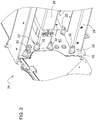
FIG. 2 is a schematic perspective view of a structural assembly of the vehicle showing a plate, an elongate member, and a gusset structure attached together. -
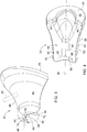
FIG. 3 is a schematic perspective view of the gusset structure from a first perspective. -
FIG. 4 is a schematic perspective view of the gusset structure from a second perspective. -
FIG. 5 is a schematic top view of the structural assembly. -
FIG. 6 is a schematic bottom view of the structural assembly. -
FIG. 7 is a schematic side plan view of the structural assembly. -
FIG. 8 is a schematic cross-sectional view of the structural assembly. - Those having ordinary skill in the art will recognize that terms such as "above," "below," "upward," "downward," "top," "bottom," etc., are used descriptively for the figures, and do not represent limitations on the scope of the disclosure, as defined by the appended claims.
- Referring to the Figures, wherein like numerals indicate corresponding parts throughout the several views, a vehicle is generally shown at 20 in
FIG. 1 . Thevehicle 20 may include any type of moveable platform, such as but not limited to a tractor, combine, trailer, car, truck, train, etc. Thevehicle 20 includes astructural assembly 22. While thestructural assembly 22 is shown incorporated into the exemplary embodiment of thevehicle 20, it should be appreciated that thestructural assembly 22 may be incorporated into some other non-moveable platform, such as but not limited to a building frame or stationary engine platform. As such, while the detailed description describes and shows thestructural assembly 22 incorporated into thevehicle 20, it should be appreciated that thestructural assembly 22 is not required to be part of thevehicle 20. - Referring to
FIG. 1 , the exemplary embodiment of thevehicle 20 is shown as a combine. The combine includes a fixedframe 24 supporting ahead unit 26. Referring toFIG. 2 , the fixedframe 24 is shown including multiplestructural assemblies 22. Eachstructural assembly 22 includes anelongate member 28 attached to aplate 30, with agusset structure 32 attached to and interconnecting theelongate member 28 and theplate 30. It should be appreciated that the use of thestructural assembly 22 in the fixedframe 24 of thevehicle 20 is merely an exemplary application of thegusset structure 32. As such, the specific details of thevehicle 20 and the fixedframe 24 are not pertinent to the teachings of this disclosure, and are therefore not described in detail herein. - In the exemplary embodiment shown in the Figures and described herein, the
plate 30, theelongate member 28, and thegusset structure 32 are formed from a metal, and are welded together to form thestructural assembly 22. However, in other embodiments, theplate 30, theelongate member 28, and thegusset structure 32 may be formed from some other non-material, such as but not limited to a plastic or nylon material, and may be attached together using some other process suitable for the particular materials and application. - The
elongate member 28 may include a solid structure, or a tubular structure defining a hollow center or core. Theelongate member 28 extends along a centrallongitudinal axis 34, and includes multiple side walls that extend parallel with the centrallongitudinal axis 34. Each of the side walls forms a substantially planar exterior surface. Each adjacent pair of side walls of theelongate member 28 is connected by a respective corner. The corners of theelongate member 28 may be rounded and include an arcuate cross section perpendicular to the centrallongitudinal axis 34. As such, each of the corners of theelongate member 28 may be referred to herein as a rounded corner. - In the exemplary embodiment shown in the Figures and described herein, and as best shown in
FIGS. 5 and6 , theelongate member 28 includes a rectangular cross section perpendicular to the centrallongitudinal axis 34. As such, theelongate member 28 may be referred to herein as therectangular member 28. Therectangular member 28 includes four side walls and four respective rounded corners. Each of the corners of therectangular member 28 form a right angle, i.e., 90°, connecting their respective side walls. However, other embodiments of theelongate member 28 may include a cross sectional shape other than the rectangular shape shown and described herein. As such, other embodiments of theelongate member 28 may include more or less than the exemplary four side walls and four corners shown in the Figures and described herein, with each of the corners defining an angle different than the exemplary right angle shown in the Figures and described herein. - Referring to
FIG. 5 , theelongate member 28 includes afirst side wall 36, asecond side wall 38, and acorner 40 disposed between and interconnecting thefirst side wall 36 and thesecond side wall 38. While the detailed description describes only thefirst side wall 36, thesecond side wall 38, and thecorner 40 therebetween, it should be appreciated that the teachings of the disclosure may be applied to the other side walls and their respective corners of theelongate member 28. Thefirst side wall 36 and thesecond side wall 38 are arranged adjacent to each other, and are positioned to form a substantially right angle therebetween. - Referring to
FIG. 2 , theplate 30 includes a flat structure having a thickness, and forms a planarexterior surface 42 to which theelongate member 28 is attached. Theelongate member 28 is attached to theplate 30 around a circumference or perimeter of theelongate member 28, either at a terminal end of theelongate member 28, or at a midsection where theelongate member 28 passes through theplate 30. Theplate 30 is positioned transverse to the centrallongitudinal axis 34 of theelongate member 28, such that the centrallongitudinal axis 34 and theelongate member 28 intersect theplate 30. Theplate 30 may include any structure forming the planarexterior surface 42 to which theelongate member 28 is attached, such as a flat plate structure, or a larger wall portion of some other structural member, such as but not limited to a tubular structure, a channel structure, an angle structure, an I-beam, etc. - The
gusset structure 32 is attached to and interconnects both theplate 30 and theelongate member 28. Due to the cross sectional geometric shape of theelongate member 28, thecorner 40 of theelongate member 28 exhibits a high strength and/or rigidity. When theelongate member 28 is attached to theplate 30, the high strength and/or rigidity of theelongate member 28 at thecorner 40 may introduce a high stress into theplate 30. Thegusset structure 32 distributes the stress in theplate 30, which would otherwise be concentrated at the joint formed between theplate 30 and theelongate member 28 in thecorner 40 connecting thefirst side wall 36 and thesecond side wall 38, over a larger area, thereby reducing the stress in theplate 30. - Referring to
FIGS. 3-7 , thegusset structure 32 includes abody 44. Thebody 44 of thegusset structure 32 may be formed from any suitable process, such as casting, forging, machining, additive manufacturing, etc. In the exemplary embodiment described herein, thegusset structure 32 includes and is formed from a metal. However, in other embodiments, thegusset structure 32 may include and be formed from a non-metal, such as but not limited to a plastic or nylon material. - The
body 44 extends along avertex axis 46 between aplate contacting end 48 and adistal end 50. Theplate contacting end 48 forms aplate mating surface 52 for engaging theplate 30. In the exemplary embodiments shown in the Figures and described herein, theelongate member 28 is positioned in a substantially orthogonal position relative to theplate 30. As such, theplate mating surface 52 is substantially perpendicular to thevertex axis 46 in order to position theelongate member 28 in the substantially orthogonal position relative to theplate 30. However, in other embodiments, in which theelongate member 28 may be angled relative to theplate 30 at an angle other than ninety degrees, thevertex axis 46 may likewise be angled relative to theplate 30 at an angle other than ninety degrees. As such, it should be appreciated that thevertex axis 46 may be arranged substantially parallel with the centrallongitudinal axis 34 of theelongate member 28. - The
plate mating surface 52 defines afirst area 54 having a perimeter that may form a partial rounded shape. Thefirst area 54 is best shown inFIG. 6 . The partial rounded shape may include any curved or rounded shape that does not include vertices that may induce localized stress. For example, the partial rounded shape is shown in the Figures having a shape defining a partial oval or a partial ellipse, in which a semi-major axis is longer than a semi-minor axis. This particular embodiment distributes the stress farther away from the joint while not including any vertices that may induce localized stress points in theplate 30. Other embodiments may include the partial rounded shape defining a partial circular shape, in which a semi-minor axis and a semi-major axis are substantially equal. It should be appreciated that the partial rounded shape may include some other shape not shown in the Figures or described herein. - As shown in
FIG. 7 , thedistal end 50 of thebody 44 is spaced from the plate contacting end 48 alength 56 along thevertex axis 46. As best shown inFIGS. 3 and 4 , thebody 44 further defines atube mating surface 58, which extends between and interconnects theplate contacting end 48 and thedistal end 50 of thebody 44. Thetube mating surface 58 includes afirst surface portion 60, asecond surface portion 62, and athird surface portion 64, all of which extend away from theplate contacting end 48 to thedistal end 50 of thebody 44. Thefirst surface portion 60 and thesecond surface portion 62 form aninterior surface angle 66 therebetween. Theinterior surface angle 66 has avertex 68 disposed on thevertex axis 46. The value of theinterior surface angle 66 is substantially equal to the value of aninterior wall angle 70 formed between thefirst side wall 36 and thesecond side wall 38. In the exemplary embodiment shown in the Figures and described herein, thefirst side wall 36 and thesecond side wall 38 are positioned to form theinterior wall angle 70 therebetween that is substantially equal to ninety degrees. As such, the exemplary embodiment of thegusset structure 32 includes theinterior surface angle 66 between thefirst surface portion 60 and thesecond surface portion 62 also equal to substantially ninety degrees. It should be appreciated that in other embodiments, in which thefirst side wall 36 and thesecond side wall 38 of theelongate member 28 form a non-right angle therebetween having a defined value greater than or less than ninety degrees, the value of the interior angle between thefirst surface portion 60 and thesecond surface portion 62 is configured to mate with and match that defined value. As such, it should be appreciated that theinterior surface angle 66 may differ from the exemplary right angle shown in the Figures and described herein. - The
first surface portion 60 of thetube mating surface 58 is positioned for engaging thefirst side wall 36 of theelongate member 28, and thesecond surface portion 62 of thetube mating surface 58 is positioned for engaging thesecond side wall 38 of theelongate member 28. Thethird surface portion 64 interconnects thefirst surface portion 60 and thesecond surface portion 62. Thethird surface portion 64 includes a cross-sectional shape, perpendicular to thevertex axis 46, which forms an arcuate shape. The arcuate cross-sectional shape of thethird surface portion 64 is sized to mate with therounded corner 40 of theelongate member 28 interconnecting thefirst side wall 36 and thesecond side wall 38. - As described above, the
plate mating surface 52 defines thefirst area 54. Thedistal end 50 of thebody 44 forms anend surface 72 that defines asecond area 74. Thesecond area 74 is best shown inFIG. 3 . In the exemplary embodiment of thegusset structure 32 shown in the Figures and described herein, thefirst area 54 of theplate mating surface 52 is larger than thesecond area 74 of theend surface 72. In other words, theplate contacting end 48 is larger than thedistal end 50. Thegusset structure 32 is configured to include the larger area of theplate mating surface 52 to spread or distribute internal forces of theplate 30 over a larger area of theplate 30 in order to reduce the internal stress in theplate 30 at the joint formed between theelongate member 28 and theplate 30 at thecorner 40 of theelongate member 28. - Referring to
FIG. 8 , thebody 44 of thegusset structure 32 includes or defines across-sectional area 100 perpendicular to thevertex axis 46. The cross-sectional area of thebody 44 increases in size with movement along thevertex axis 46, in a direction from thedistal end 50 toward theplate contacting end 48, indicated byarrow 76 shown inFIG. 7 . By doing so, the size of theplate contacting end 48 is increased to provide the larger stress distribution area. - In the exemplary embodiment of the
gusset structure 32 shown in the Figures and described herein, the cross-sectional area of thebody 44 changes at a variable rate-of-change perunit length 56 along thevertex axis 46. As such, when viewed from the side, as shown inFIG. 7 , thegusset structure 32 includes anexterior surface profile 98 connecting thedistal end 50 and theplate contacting end 48 that exhibits a generallyconcave side profile 98. However, in other embodiments, the cross-sectional area of thebody 44 may change at a constant or non-variable rate-of-change perunit length 56 along thevertex axis 46, such that when viewed from the side, thegusset structure 32 includes an exterior surface profile connecting thedistal end 50 and theplate contacting end 48 that exhibits a generally triangular side profile. - Referring to
FIG. 4 , thefirst surface portion 60 of thetube mating surface 58 defines a firstouter edge 78 at an intersection of thefirst surface portion 60 and anexterior surface 80 of thebody 44. Thebody 44 defines afirst distance 82 between thevertex axis 46 and the firstouter edge 78 at thedistal end 50 of thebody 44. Thebody 44 defines asecond distance 84 between thevertex axis 46 and the firstouter edge 78 at theplate contacting end 48. Because thedistal end 50 of thebody 44 is smaller than theplate contacting end 48, thefirst distance 82 is less than thesecond distance 84. - Referring to
FIG. 4 , thesecond surface portion 62 of thetube mating surface 58 defines a secondouter edge 86 at an intersection of thesecond surface portion 62 and theexterior surface 80 of thebody 44. Thebody 44 defines athird distance 88 between thevertex axis 46 and the secondouter edge 86 at thedistal end 50 of thebody 44. Thebody 44 defines afourth distance 90 between thevertex axis 46 and the secondouter edge 86 at theplate contacting end 48. Because thedistal end 50 of thebody 44 is smaller than theplate contacting end 48, thethird distance 88 is less than thefourth distance 90. - In the exemplary embodiment shown in the Figures and described herein, the
first distance 82 and thethird distance 88 are substantially equal, and thesecond distance 84 and thefourth distance 90 are substantially equal. However, in other embodiments, thefirst distance 82 and thethird distance 88 may differ, and thesecond distance 84 and thefourth distance 90 may differ. - Referring to
FIG. 8 , theplate contacting end 48 includes acentral axis 92 disposed on theplate mating surface 52. Thecentral axis 92 of theplate contacting end 48 extends from thevertex axis 46 radially outward and away from the roundedcorner 40 of theelongate member 28, toward the perimeter of theplate mating surface 52. Thecentral axis 92 bisects theplate mating surface 52 to form two substantially equal halves. In the exemplary embodiment shown in the Figures and described herein, thecentral axis 92 bisects anexternal wall angle 94 formed between thefirst side wall 36 and thesecond side wall 38 of theelongate member 28. As such, in the exemplary embodiment shown in the Figures, in which theelongate member 28 is rectangular forming a right angle between thefirst side wall 36 and thesecond side wall 38, theexternal wall angle 94 is substantially equal to two hundred seventy degrees, and thecentral axis 92 bisects theexternal wall angle 94, with a first half of theplate mating surface 52 disposed on a first side of thecentral axis 92, and a second half of theplate mating surface 52 disposed in a second side of thecentral axis 92. - The components of the
structural assembly 22, i.e., theplate 30, theelongate member 28, and thegusset structure 32, are permanently and fixedly attached together. The components of thestructural assembly 22 may be attached together in any suitable manner. For example, the components of thestructural assembly 22 may be welded together to form a strong connection therebetween. In other embodiments, other attachment processes, such as but not limited to bonding with an adhesive, may be used to connect the components of thestructural assembly 22. - In order to improve assembly efficiency, the
body 44 of the gusset assembly may be magnetized so that a magnetic force secures the gusset assembly to theplate 30 and/or theelongate member 28. The magnetic force may hold the gusset assembly in place allowing the final attachment process to be executed. For example, the magnetic force may hold the gusset assembly in place relative to theplate 30 and/or theelongate member 28 while the gusset assembly is welded to theplate 30 and theelongate member 28. - In other embodiments, the
gusset structure 32 may be formed to include aremoveable handle 96, shown inFIG. 3 , that extends outwardly from thebody 44. The removable handle may be shaped to provide a convenient hand hold that enables an assembly person or a robotic machine to easily grasp and hold the gusset assembly in place relative to theplate 30 and theelongate member 28 allowing the final attachment process to be executed. - While the above describes example embodiments of the present disclosure, these descriptions should not be viewed in a limiting sense. Rather, other variations and modifications may be made without departing from the scope and spirit of the present disclosure as defined in the appended claims.
Claims (20)
- A gusset structure for distributing stress at a joint formed between a plate and an elongate member, the gusset structure comprising:a body having a plate contacting end forming a plate mating surface for engaging the plate;wherein the body forms a tube mating surface having a first surface portion and a second surface portion forming an interior surface angle therebetween and extending away from the plate contacting end, with the interior surface angle having a vertex disposed on a vertex axis that intersects the plate mating surface;wherein the first surface portion of the tube mating surface is positioned for engaging a first side wall of the elongate member, and the second surface portion of the tube mating surface is positioned for engaging a second side wall of the elongate member.
- The gusset structure set forth in claim 1, wherein the body includes a distal end spaced from the plate contacting end a length along the vertex axis, with the tube mating surface extending between and interconnecting the plate contacting end and the distal end of the body.
- The gusset structure set forth in claim 2, wherein the plate mating surface defines a first area, and the distal end forms an end surface defining a second area, with the first area of the plate mating surface being larger than the second area of the end surface.
- The gusset structure set forth in claim 2, wherein the body includes a cross-sectional area perpendicular to the vertex axis, wherein the cross-sectional area of the body increases in size with movement along the vertex axis in a direction from the distal end toward the plate contacting end.
- The gusset structure set forth in claim 4, wherein the cross-sectional area of the body changes at a variable rate-of-change per unit length along the vertex axis.
- The gusset structure set forth in claim 1, wherein the first surface portion of the tube mating surface defines a first outer edge at an intersection of the first surface portion and an exterior surface of the body, and wherein the second surface portion of the tube mating surface defines a second outer edge at an intersection of the second surface portion and the exterior surface of the body.
- The gusset structure set forth in claim 6, further comprising a first distance between the vertex axis and the first outer edge at the distal end of the body, and a second distance between the vertex axis and the first outer edge at the plate contacting end, with the first distance being less than the second distance.
- The gusset structure set forth in claim 7, further comprising a third distance between the vertex axis and the second outer edge at the distal end of the body, and a fourth distance between the vertex axis and the second outer edge at the plate contacting end, with the third distance being less than the fourth distance.
- The gusset structure set forth in claim 8, wherein the first distance and the third distance are substantially equal, and wherein the second distance and the fourth distance are substantially equal.
- The gusset structure set forth in claim 1, wherein the plate mating surface forms a partial rounded shape.
- The gusset structure set forth in claim 1, wherein the tube mating surface includes a third surface portion interconnecting the first surface portion and the second surface portion.
- The gusset structure set forth in claim 11, wherein the third surface portion includes a cross-sectional shape perpendicular to the vertex axis forming an arcuate shape and sized to mate with a rounded corner of the elongate member interconnecting the first side wall and the second side wall of the elongate member.
- The gusset structure set forth in claim 1, wherein the plate mating surface is substantially perpendicular to the vertex axis.
- The gusset structure set forth in claim 1, wherein the body is magnetized.
- The gusset structure set forth in claim 1, further comprising a removeable handle extending outwardly from the body.
- A structural assembly comprising:a plate;an elongate member attached to the plate;wherein the elongate member extends along a central longitudinal axis and includes a first side wall and a second side wall arranged adjacent to each other and positioned to form an interior wall angle therebetween;wherein the plate is positioned transverse to the central longitudinal axis of the elongate member; anda gusset structure attached to both the plate and the elongate member, the gusset structure including:a body having a plate contacting end forming a plate mating surface in abutting engagement with the plate;wherein the body forms a tube mating surface having a first surface portion and a second surface portion forming an interior surface angle therebetween and extending away from the plate contacting end, with the interior surface angle having a vertex disposed on a vertex axis that intersects the plate mating surface, and with the interior surface angle substantially equal to the interior wall angle;wherein the first surface portion of the tube mating surface is disposed against the first side wall of the elongate member, and the second surface portion of the tube mating surface is disposed against the second side wall of the elongate member;wherein the body includes a distal end spaced from the plate contacting end a length along the vertex axis, with the tube mating surface extending between and interconnecting the plate contacting end and the distal end of the body; andwherein the plate mating surface defines a first area, and the distal end forms an end surface defining a second area, with the first area of the plate mating surface being larger than the second area of the end surface.
- The vehicle set forth in claim 16, wherein the body includes a cross-sectional area perpendicular to the vertex axis, wherein the cross-sectional area of the body increases in size with movement along the vertex axis in a direction from the distal end toward the plate contacting end.
- The vehicle set forth in claim 16, wherein:the first surface portion of the tube mating surface defines a first outer edge at an intersection of the first surface portion and an exterior surface of the body;the body defines a first distance between the vertex axis and the first outer edge at the distal end of the body;the body defines a second distance between the vertex axis and the first outer edge at the plate contacting end;the first distance is less than the second distance;the second surface portion of the tube mating surface defines a second outer edge at an intersection of the second surface portion and the exterior surface of the body;the body defines a third distance between the vertex axis and the second outer edge at the distal end of the body;the body defines a fourth distance between the vertex axis and the second outer edge at the plate contacting end; andthe third distance is less than the fourth distance.
- The vehicle set forth in claim 16, wherein the plate mating surface forms a partial elliptical shape.
- The vehicle set forth in claim 16, wherein the tube mating surface includes a third surface portion interconnecting the first surface portion and the second surface portion, and wherein the third surface portion includes a cross-sectional shape perpendicular to the vertex axis forming an arcuate shape and sized to mate with a rounded corner of the elongate member interconnecting the first side wall and the second side wall of the elongate member.
Applications Claiming Priority (1)
| Application Number | Priority Date | Filing Date | Title |
|---|---|---|---|
| US16/374,990 US11293468B2 (en) | 2019-04-04 | 2019-04-04 | Universal castings for rectangular tube corner stress relief |
Publications (2)
| Publication Number | Publication Date |
|---|---|
| EP3719328A1 true EP3719328A1 (en) | 2020-10-07 |
| EP3719328B1 EP3719328B1 (en) | 2026-01-14 |
Family
ID=69953902
Family Applications (1)
| Application Number | Title | Priority Date | Filing Date |
|---|---|---|---|
| EP20164958.9A Active EP3719328B1 (en) | 2019-04-04 | 2020-03-23 | Universal castings for rectangular tube corner stress releif |
Country Status (3)
| Country | Link |
|---|---|
| US (1) | US11293468B2 (en) |
| EP (1) | EP3719328B1 (en) |
| CN (1) | CN111795041B (en) |
Citations (3)
| Publication number | Priority date | Publication date | Assignee | Title |
|---|---|---|---|---|
| DE2744523A1 (en) * | 1976-10-05 | 1978-04-06 | Electrolux Ab | ANGLE PIECE FOR FASTENING A LONGITUDINAL PART ON A SURFACE |
| US4232881A (en) * | 1977-08-10 | 1980-11-11 | Volkswagenwerk Aktiengesellschaft | Suspension arrangement for motor vehicles |
| US20130214228A1 (en) * | 2012-02-20 | 2013-08-22 | Jayme M. Sneith | Baluster Bracket Assembly |
Family Cites Families (16)
| Publication number | Priority date | Publication date | Assignee | Title |
|---|---|---|---|---|
| DE3536901A1 (en) * | 1985-10-16 | 1987-04-16 | Stanelle Karl Heinz | Railing for industrial buildings |
| US5979130A (en) * | 1996-10-10 | 1999-11-09 | Simpson Strong-Tie Company, Inc. | Connector with concave seat |
| US6736355B2 (en) * | 2002-06-14 | 2004-05-18 | Delphi Technologies, Inc. | Arrangement and bracket for a sensor |
| KR200332577Y1 (en) | 2003-08-07 | 2003-11-07 | 안상도 | Durable Goods Coupling Bracket |
| CN201092994Y (en) * | 2007-08-27 | 2008-07-30 | 林庆义 | Pipe fitting connecting structure |
| US7942385B2 (en) * | 2007-09-25 | 2011-05-17 | Aluspek Products, Inc. | Adjustable railing post bracket |
| US8070216B2 (en) * | 2008-03-27 | 2011-12-06 | Nova Bus, Division De Groupe Volvo Canada Inc. | Vehicle frame with stress relief feature |
| US8100618B2 (en) * | 2008-07-18 | 2012-01-24 | Illinois Tool Works Inc. | Apparatus and method of making a heel-less nail |
| CN105909636B (en) * | 2010-04-26 | 2019-07-30 | 布兰金系统公司 | Corner piece for mechanically interlocking frame members |
| US9388836B2 (en) * | 2012-05-24 | 2016-07-12 | Donald B. Larson | Slip fitting holding device and system |
| CN202934279U (en) * | 2012-09-05 | 2013-05-15 | 天津福臻工业装备有限公司 | L-shaped transition block |
| FR3025478B1 (en) * | 2014-09-04 | 2018-02-16 | Alstom Transport Technologies | STRUCTURE FOR AN ELECTRICAL INSTALLATION OF A RAILWAY VEHICLE AND ASSOCIATED RAILWAY VEHICLE |
| CN205128847U (en) | 2015-10-21 | 2016-04-06 | 南车长江车辆有限公司 | Thin wall frame type steel -casting cracking strip structure |
| JP6259476B2 (en) * | 2016-01-13 | 2018-01-10 | 本田技研工業株式会社 | Vehicle rear structure |
| US10959521B2 (en) * | 2017-05-08 | 2021-03-30 | Snap-On Incorporated | Corner reinforcement gusset |
| CN108591202B (en) * | 2018-06-29 | 2023-11-21 | 中冶南方工程技术有限公司 | Lining plate fixing structure and fixing method |
-
2019
- 2019-04-04 US US16/374,990 patent/US11293468B2/en active Active
-
2020
- 2020-02-25 CN CN202010118104.8A patent/CN111795041B/en active Active
- 2020-03-23 EP EP20164958.9A patent/EP3719328B1/en active Active
Patent Citations (3)
| Publication number | Priority date | Publication date | Assignee | Title |
|---|---|---|---|---|
| DE2744523A1 (en) * | 1976-10-05 | 1978-04-06 | Electrolux Ab | ANGLE PIECE FOR FASTENING A LONGITUDINAL PART ON A SURFACE |
| US4232881A (en) * | 1977-08-10 | 1980-11-11 | Volkswagenwerk Aktiengesellschaft | Suspension arrangement for motor vehicles |
| US20130214228A1 (en) * | 2012-02-20 | 2013-08-22 | Jayme M. Sneith | Baluster Bracket Assembly |
Also Published As
| Publication number | Publication date |
|---|---|
| CN111795041A (en) | 2020-10-20 |
| US20200318310A1 (en) | 2020-10-08 |
| EP3719328B1 (en) | 2026-01-14 |
| US11293468B2 (en) | 2022-04-05 |
| BR102020002915A2 (en) | 2020-10-27 |
| CN111795041B (en) | 2024-03-22 |
Similar Documents
| Publication | Publication Date | Title |
|---|---|---|
| US9139146B2 (en) | Impact absorbing member for vehicle | |
| KR100680165B1 (en) | Automotive Suspension Arm with Eye Beam Structure | |
| US8322738B2 (en) | Stabilizing strut for a chassis of a vehicle | |
| US9327564B2 (en) | Hitch ball mount | |
| CN104254453A (en) | Vehicle suspension arm | |
| JP6431380B2 (en) | Vibration isolator | |
| US11293468B2 (en) | Universal castings for rectangular tube corner stress relief | |
| US11827298B2 (en) | Vehicle knuckle | |
| EP2771590A1 (en) | Rubber bushing | |
| CN105570266A (en) | Fastening apparatus for vehicle sheet component | |
| BR102020002915B1 (en) | REINFORCEMENT STRUCTURE, AND STRUCTURAL ASSEMBLY | |
| JPH10507144A (en) | Sheet metal parts | |
| JP7368730B2 (en) | rear subframe | |
| US12037044B2 (en) | Lower vehicle body structure | |
| CN115135568B (en) | steering knuckle for vehicles | |
| US9889892B2 (en) | Attachment bulkhead for body structures | |
| CN105128600A (en) | Axle housing, axle, vehicle and method for manufacturing the axle housing | |
| JP6131787B2 (en) | Vehicle suspension arm | |
| JP3655102B2 (en) | Aluminum alloy link member | |
| US11084538B2 (en) | Multi-flange extrusion member | |
| JP2019163803A (en) | Composite material assembly | |
| JPH068835U (en) | bush | |
| JP3066240U (en) | Automotive engine mount | |
| JP6761644B2 (en) | Fittings, masts, and ships | |
| CA2943926A1 (en) | Aerodynamic nose device |
Legal Events
| Date | Code | Title | Description |
|---|---|---|---|
| PUAI | Public reference made under article 153(3) epc to a published international application that has entered the european phase |
Free format text: ORIGINAL CODE: 0009012 |
|
| STAA | Information on the status of an ep patent application or granted ep patent |
Free format text: STATUS: THE APPLICATION HAS BEEN PUBLISHED |
|
| AK | Designated contracting states |
Kind code of ref document: A1 Designated state(s): AL AT BE BG CH CY CZ DE DK EE ES FI FR GB GR HR HU IE IS IT LI LT LU LV MC MK MT NL NO PL PT RO RS SE SI SK SM TR |
|
| AX | Request for extension of the european patent |
Extension state: BA ME |
|
| STAA | Information on the status of an ep patent application or granted ep patent |
Free format text: STATUS: REQUEST FOR EXAMINATION WAS MADE |
|
| 17P | Request for examination filed |
Effective date: 20210407 |
|
| RBV | Designated contracting states (corrected) |
Designated state(s): AL AT BE BG CH CY CZ DE DK EE ES FI FR GB GR HR HU IE IS IT LI LT LU LV MC MK MT NL NO PL PT RO RS SE SI SK SM TR |
|
| STAA | Information on the status of an ep patent application or granted ep patent |
Free format text: STATUS: EXAMINATION IS IN PROGRESS |
|
| 17Q | First examination report despatched |
Effective date: 20220803 |
|
| GRAP | Despatch of communication of intention to grant a patent |
Free format text: ORIGINAL CODE: EPIDOSNIGR1 |
|
| STAA | Information on the status of an ep patent application or granted ep patent |
Free format text: STATUS: GRANT OF PATENT IS INTENDED |
|
| INTG | Intention to grant announced |
Effective date: 20250924 |
|
| GRAS | Grant fee paid |
Free format text: ORIGINAL CODE: EPIDOSNIGR3 |
|
| GRAA | (expected) grant |
Free format text: ORIGINAL CODE: 0009210 |
|
| STAA | Information on the status of an ep patent application or granted ep patent |
Free format text: STATUS: THE PATENT HAS BEEN GRANTED |
|
| AK | Designated contracting states |
Kind code of ref document: B1 Designated state(s): AL AT BE BG CH CY CZ DE DK EE ES FI FR GB GR HR HU IE IS IT LI LT LU LV MC MK MT NL NO PL PT RO RS SE SI SK SM TR |
|
| REG | Reference to a national code |
Ref country code: CH Ref legal event code: F10 Free format text: ST27 STATUS EVENT CODE: U-0-0-F10-F00 (AS PROVIDED BY THE NATIONAL OFFICE) Effective date: 20260114 Ref country code: GB Ref legal event code: FG4D |
|
| REG | Reference to a national code |
Ref country code: DE Ref legal event code: R096 Ref document number: 602020065413 Country of ref document: DE |
|
| REG | Reference to a national code |
Ref country code: IE Ref legal event code: FG4D |
|
| PGFP | Annual fee paid to national office [announced via postgrant information from national office to epo] |
Ref country code: DE Payment date: 20260219 Year of fee payment: 7 |