EP3719277B1 - Fluide caloporteur pour système de refroidissement de turboréacteur pour aéronef - Google Patents
Fluide caloporteur pour système de refroidissement de turboréacteur pour aéronef Download PDFInfo
- Publication number
- EP3719277B1 EP3719277B1 EP20165533.9A EP20165533A EP3719277B1 EP 3719277 B1 EP3719277 B1 EP 3719277B1 EP 20165533 A EP20165533 A EP 20165533A EP 3719277 B1 EP3719277 B1 EP 3719277B1
- Authority
- EP
- European Patent Office
- Prior art keywords
- heat
- transfer fluid
- exchanger
- nacelle
- lubricant
- Prior art date
- Legal status (The legal status is an assumption and is not a legal conclusion. Google has not performed a legal analysis and makes no representation as to the accuracy of the status listed.)
- Active
Links
Images
Classifications
-
- F—MECHANICAL ENGINEERING; LIGHTING; HEATING; WEAPONS; BLASTING
- F02—COMBUSTION ENGINES; HOT-GAS OR COMBUSTION-PRODUCT ENGINE PLANTS
- F02C—GAS-TURBINE PLANTS; AIR INTAKES FOR JET-PROPULSION PLANTS; CONTROLLING FUEL SUPPLY IN AIR-BREATHING JET-PROPULSION PLANTS
- F02C7/00—Features, components parts, details or accessories, not provided for in, or of interest apart form groups F02C1/00 - F02C6/00; Air intakes for jet-propulsion plants
- F02C7/12—Cooling of plants
- F02C7/16—Cooling of plants characterised by cooling medium
-
- F—MECHANICAL ENGINEERING; LIGHTING; HEATING; WEAPONS; BLASTING
- F02—COMBUSTION ENGINES; HOT-GAS OR COMBUSTION-PRODUCT ENGINE PLANTS
- F02C—GAS-TURBINE PLANTS; AIR INTAKES FOR JET-PROPULSION PLANTS; CONTROLLING FUEL SUPPLY IN AIR-BREATHING JET-PROPULSION PLANTS
- F02C7/00—Features, components parts, details or accessories, not provided for in, or of interest apart form groups F02C1/00 - F02C6/00; Air intakes for jet-propulsion plants
- F02C7/12—Cooling of plants
- F02C7/14—Cooling of plants of fluids in the plant, e.g. lubricant or fuel
-
- F—MECHANICAL ENGINEERING; LIGHTING; HEATING; WEAPONS; BLASTING
- F02—COMBUSTION ENGINES; HOT-GAS OR COMBUSTION-PRODUCT ENGINE PLANTS
- F02C—GAS-TURBINE PLANTS; AIR INTAKES FOR JET-PROPULSION PLANTS; CONTROLLING FUEL SUPPLY IN AIR-BREATHING JET-PROPULSION PLANTS
- F02C7/00—Features, components parts, details or accessories, not provided for in, or of interest apart form groups F02C1/00 - F02C6/00; Air intakes for jet-propulsion plants
- F02C7/12—Cooling of plants
- F02C7/16—Cooling of plants characterised by cooling medium
- F02C7/18—Cooling of plants characterised by cooling medium the medium being gaseous, e.g. air
-
- F—MECHANICAL ENGINEERING; LIGHTING; HEATING; WEAPONS; BLASTING
- F05—INDEXING SCHEMES RELATING TO ENGINES OR PUMPS IN VARIOUS SUBCLASSES OF CLASSES F01-F04
- F05D—INDEXING SCHEME FOR ASPECTS RELATING TO NON-POSITIVE-DISPLACEMENT MACHINES OR ENGINES, GAS-TURBINES OR JET-PROPULSION PLANTS
- F05D2260/00—Function
- F05D2260/20—Heat transfer, e.g. cooling
- F05D2260/213—Heat transfer, e.g. cooling by the provision of a heat exchanger within the cooling circuit
-
- F—MECHANICAL ENGINEERING; LIGHTING; HEATING; WEAPONS; BLASTING
- F05—INDEXING SCHEMES RELATING TO ENGINES OR PUMPS IN VARIOUS SUBCLASSES OF CLASSES F01-F04
- F05D—INDEXING SCHEME FOR ASPECTS RELATING TO NON-POSITIVE-DISPLACEMENT MACHINES OR ENGINES, GAS-TURBINES OR JET-PROPULSION PLANTS
- F05D2260/00—Function
- F05D2260/20—Heat transfer, e.g. cooling
- F05D2260/232—Heat transfer, e.g. cooling characterized by the cooling medium
-
- F—MECHANICAL ENGINEERING; LIGHTING; HEATING; WEAPONS; BLASTING
- F05—INDEXING SCHEMES RELATING TO ENGINES OR PUMPS IN VARIOUS SUBCLASSES OF CLASSES F01-F04
- F05D—INDEXING SCHEME FOR ASPECTS RELATING TO NON-POSITIVE-DISPLACEMENT MACHINES OR ENGINES, GAS-TURBINES OR JET-PROPULSION PLANTS
- F05D2260/00—Function
- F05D2260/98—Lubrication
-
- Y—GENERAL TAGGING OF NEW TECHNOLOGICAL DEVELOPMENTS; GENERAL TAGGING OF CROSS-SECTIONAL TECHNOLOGIES SPANNING OVER SEVERAL SECTIONS OF THE IPC; TECHNICAL SUBJECTS COVERED BY FORMER USPC CROSS-REFERENCE ART COLLECTIONS [XRACs] AND DIGESTS
- Y02—TECHNOLOGIES OR APPLICATIONS FOR MITIGATION OR ADAPTATION AGAINST CLIMATE CHANGE
- Y02T—CLIMATE CHANGE MITIGATION TECHNOLOGIES RELATED TO TRANSPORTATION
- Y02T50/00—Aeronautics or air transport
- Y02T50/60—Efficient propulsion technologies, e.g. for aircraft
Definitions
- the present invention relates to the field of fluids for aircraft turbojet cooling systems.
- An aircraft is powered by one or more propulsion units, each comprising a turbojet engine housed in a nacelle.
- Each propulsion unit is attached to the aircraft by a mast generally located under or on a wing or at the fuselage of the aircraft.
- a turbojet engine can also be called an engine.
- engine and turbojet engine will be used interchangeably.
- a nacelle generally has a tubular structure comprising an upstream section comprising an air inlet upstream of the turbojet, a middle section intended to surround a fan of the turbojet, a downstream section capable of housing thrust reversal means and intended to surround the combustion chamber of the turbojet, and is generally terminated by an ejection nozzle whose outlet is located downstream of the turbojet.
- a nacelle usually comprises an external structure comprising a fixed part and a mobile part (thrust reversal means), and a fixed internal structure, called Inner Fixed Structure (IFS), concentric with the external structure.
- IFS Inner Fixed Structure
- the fixed internal structure surrounds the core of the turbojet engine behind the fan.
- These external and internal structures define an annular flow vein, also called secondary vein, aimed at channeling a cold air flow, called secondary, which circulates outside the turbojet engine.
- the external structure comprises an external fairing defining an external aerodynamic surface, intended to be in contact with an external air flow, and an internal fairing defining an internal aerodynamic surface, intended to be in contact with the secondary air flow.
- the internal and external fairings are connected upstream by a leading edge wall forming an air inlet lip.
- the turbojet engine comprises a set of blades (compressor and possibly fan or unducted propeller) driven in rotation by a gas generator through a set of transmission means.
- a lubricant distribution system is provided in the turbojet to ensure good lubrication of these transmission means and to cool them.
- the lubricant is oil.
- the terms lubricant and oil will be used interchangeably.
- a cooling system with a heat exchanger is used to cool the lubricant.
- a known method consists of cooling the lubricant by circulation through an air/oil exchanger using cold air from the secondary stream (so-called cold flow) of the nacelle or one of the first stages of the compressor, to cool the oil of the turbojet.
- an exchanger is a finned exchanger. It has fins in the cold air flow which disturb the flow of the air flow in the secondary stream or in the compressor, which causes pressure losses (drag), and therefore performance losses for the aircraft in terms of fuel consumption (FB (Fuel Burn) parameter).
- Another known method consists in cooling the lubricant by means of a cooling system comprising an air/oil exchanger using cold air taken from outside the nacelle or from the secondary stream, by a scoop arranged respectively on the external or internal fairing of the nacelle, the cold air being circulated through the exchanger and being able to be used for defrosting the nacelle, once heated by the lubricant, by circulation in ducts arranged in contact with the walls of the external structure of the nacelle, for example at the air inlet lip.
- a known solution for limiting airflow disturbances consists in providing a cooling system comprising a surface exchanger between the lubricant and air.
- a cooling system comprises a closed-circuit lubricant circulation duct.
- the lubricant circulation duct comprises a portion arranged in the nacelle in contact with the internal and/or external fairing of the nacelle.
- the portion arranged in the nacelle in contact with the internal and/or external fairing of the nacelle comprises a plurality of channels arranged in parallel, said channels being formed by a double wall of the internal and/or external fairing, this being referred to as a structural surface exchanger.
- the lubricant is flammable at temperatures of around 260°C, it is dangerous to circulate it along the entire internal or external fairing of the nacelle. Indeed, certain areas of the nacelle, called fire zones, are very sensitive to flames, because they contain flammable products and a source of ignition. For example, certain areas of the downstream section intended to surround the combustion chamber of the turbojet engine (called core compartment) are systematically declared fire zones, as well as potentially certain areas of the middle section, intended to surround the turbojet engine fan (called fan zones).
- the lubricant is very viscous at low temperatures, so a means of defrosting is required to circulate the lubricant to certain areas of the nacelle exposed to very low temperatures.
- the document FR 2 914 365 A1 describes the use of a heat transfer fluid in an aircraft turbojet cooling system.
- An aim of the present invention is to use, in a turbojet cooling system for an aircraft, a heat transfer fluid that is less flammable at temperatures of the order of 130°C, and less viscous at low temperature than a turbojet lubricant, the heat transfer fluid being intended to circulate in contact with the external and/or internal fairing of the nacelle in order to cool it, then in contact with the lubricant in order to cool the lubricant.
- the invention relates to the use, in a turbojet cooling system for an aircraft surrounded by a nacelle, of a heat transfer fluid that is less flammable than a turbojet lubricant, and liquid at temperatures between -70°C and +175°C, the heat transfer fluid being intended to circulate in a closed-circuit circulation duct comprising a first surface exchanger between the heat transfer fluid and air, at the external and/or internal fairing of the nacelle, and a second exchanger between the heat transfer fluid and the lubricant.
- the heat transfer fluid is flammable at higher temperatures than the lubricant. Since the lubricant is generally flammable at 260°C (flash point), the heat transfer fluid is flammable at higher temperatures.
- the entire internal and external fairing of the nacelle can be used for the circulation of heat transfer fluid, without requiring any defrosting means.
- the heat transfer fluid can also circulate in the fixed internal structure of the nacelle.
- the first exchanger is called the cold source exchanger, while the second exchanger is called the hot source exchanger.
- the first surface exchanger comprises a plurality of channels arranged in parallel.
- the first exchanger is formed at least in part by a double wall of the internal and/or external fairing of the nacelle.
- the first exchanger is formed at least in part by a double wall of the fixed internal structure of the nacelle.
- the heat transfer fluid is non-flammable.
- the heat transfer fluid is liquid at temperatures between -70°C and +175°C at pressures below 10 bars.
- the heat transfer fluid (C) has an ignition point greater than 260°C, a combustion point greater than 280°C and an autogenous ignition temperature greater than 300°C.
- the heat transfer fluid has an ignition point greater than 260°C, a combustion point greater than 280°C and an autogenous ignition temperature greater than 400°C.
- the heat transfer fluid has a dielectric constant less than 6.
- the heat transfer fluid belongs to the family of hydrofluoroethers (HFE). In this way, the fluid is able to remain in the liquid state at temperatures below 130°C at atmospheric pressure, and therefore throughout the nacelle.
- HFE hydrofluoroethers
- the heat transfer fluid belongs to the family of silicate esters.
- the heat transfer fluid circulation conduit comprises means for regulating the volume occupied by the heat transfer fluid in the heat transfer fluid circulation conduit, preferably comprising an expansion tank.
- the fluid can be used at temperatures above its boiling point at atmospheric pressure.
- Such an expansion tank is a closed reservoir.
- the pressure in the expansion tank is directly related to the volume occupied by the heat transfer fluid in the expansion tank. This characteristic advantageously makes it possible to control a maximum and/or minimum pressure in certain portions of the heat transfer fluid circulation pipe by acting solely on the capacity (volume) of the tank.
- the first surface exchanger comprises a plurality of channels arranged in parallel.
- the first exchanger is formed at least in part by a double wall of the internal and/or external fairing of the nacelle.
- the first exchanger is formed at least in part by a double wall of the fixed internal structure of the nacelle.
- the cooling system comprises several first surface exchangers.
- the first surface exchangers are formed at least in part by a double wall of the internal fairing and/or the external fairing and/or the fixed internal structure of the nacelle.
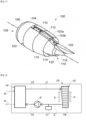
- FIG. 1 illustrates a nacelle 100 suspended from a pylon 102 intended to be attached to a wing (not shown) of an aircraft (not shown).
- the nacelle 100 comprises an external structure 103 comprising an upstream section 104 provided with a lip 106 forming an air inlet 108, a middle section 110, and a downstream section 112.
- the nacelle further comprises a fixed internal structure 114 surrounding a downstream portion of a turbojet (not shown) concentrically with respect to the downstream section 112.
- the fixed internal structure 114 and the external structure 103 delimit a vein annular 115 defining a passage for a cold secondary air flow (not shown).
- the nacelle 100 also includes an exhaust nozzle 116 comprising a gas exhaust cone 118 and a gas exhaust nozzle 120.
- the exhaust cone 118 and the exhaust nozzle 120 define a passage for a flow of hot air (not shown) exiting the turbojet engine (not shown).
- the external structure 103 comprises an external fairing 103a defining an external aerodynamic surface, and an internal fairing 103b defining an internal aerodynamic surface, the external fairing 103a and internal fairing 103b being connected upstream by a leading edge wall (not shown) forming the lip 106 of the air inlet 108.
- the nacelle includes a surface exchanger called cold source 12 ( figure 2 ) between a heat transfer fluid C ( figure 2 ) to be cooled and a cold air flow F ( figure 2 ).
- the cold air flow F can be the secondary air flow or an outside air flow.
- the cold source surface exchanger 12 is arranged in the external structure 103. It is intended to cooperate with a so-called hot source exchanger 14 ( figure 2 ) between a lubricant H ( figure 2 ) for the turbojet to be cooled and the heat transfer fluid C, via a circulation duct 15 ( figure 2 ) of heat transfer fluid C.
- the hot source exchanger 14 can for example be arranged in the turbojet (not shown).
- the cold source surface exchanger assembly 12 and the hot source exchanger 14 form a cooling system 10 ( figure 2 ) of the turbojet.
- FIG. 1 illustrates the cooling system 10 of the turbojet.
- the cooling system 10 comprises the cold source surface exchanger 12 and the hot source exchanger 14.
- the heat transfer fluid C circulates in the circulation duct 15 and in the cold source surface exchanger 12 where it is cooled by cold air F.
- the heat transfer fluid C thus cooled then circulates in the hot source exchanger 14 where it is heated by the lubricant H.
- the heat transfer fluid C cooled by the cold source surface exchanger makes it possible to cool the lubricant H.
- the heat transfer fluid C is intended to circulate both in the cold source surface exchanger 12 and in the hot source exchanger 14.
- the heat transfer fluid C is NovecTM 7500.
- HFE hydrofluoroether
- This fluid is non-flammable, and liquid at temperatures between -70°C and +175°C at pressures below 10 bars. It has an ignition point above 260°C, a combustion point above 280°C and an autogenous ignition temperature above 400°C. It also has a dielectric constant below 6.
- a pump P allows the circulation of the heat transfer fluid C between the cold source surface exchanger 10 and the hot source exchanger 14.
- An expansion tank 17 makes it possible to define a maximum and/or minimum pressure in certain portions of the circulation pipe 15 of the heat transfer fluid C.
- the expansion tank 17 is closed so that its volume is linked to the pressure of the circulation pipe 15 of the heat transfer fluid C. It is filled with heat transfer fluid C and a volume without heat transfer fluid, called a gaseous headspace, which acts as a buffer. It makes it possible to limit the pressure in the circulation pipe 15 of the heat transfer fluid during the expansion of the fluid as a function of the temperature.
- the expansion tank 17 is a means of regulating the volume occupied by the heat transfer fluid C in the heat transfer fluid circulation conduit 15.
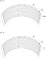
- FIG 3 illustrates the external fairing 103a at the downstream section 112 of a nacelle 100 ( figure 1 ) comprising a cold source surface exchanger 12.
- the cold source surface exchanger 12 comprises a plurality of channels 16 arranged in parallel, in which the heat transfer fluid C circulates.
- the channels 16 are arranged in contact with the external fairing 103a. They are formed by a double wall of the external fairing 103a of the nacelle. This is then referred to as a structural surface exchanger.
- the external fairing 103a being in contact with a flow of cold external air, the heat exchange is carried out by convection with the flow of cold external air.
- the cold source surface exchanger 12 is arranged in contact with the internal fairing 103b and the heat exchange is carried out by convection with the secondary cold air flow.
- the cold source surface exchanger 12 is arranged in contact with the external fairing 103a and the internal fairing 103b and the heat exchange is carried out by convection with the external cold air flow and the secondary cold air flow.
- FIG 4 illustrates a portion of the fixed internal structure 114 of a nacelle 100 ( figure 1 ) comprising a cold source surface exchanger 12 as described with regard to the figure 3 .
- the fixed internal structure 114 is in contact with the secondary air flow.
- the heat exchange is therefore carried out by convection with the secondary air flow.
Landscapes
- Engineering & Computer Science (AREA)
- Chemical & Material Sciences (AREA)
- Combustion & Propulsion (AREA)
- Mechanical Engineering (AREA)
- General Engineering & Computer Science (AREA)
- Heat-Exchange Devices With Radiators And Conduit Assemblies (AREA)
- Structures Of Non-Positive Displacement Pumps (AREA)
Description
- La présente invention se rapporte au domaine des fluides pour systèmes de refroidissement de turboréacteur pour aéronef.
- Un aéronef est propulsé par un ou plusieurs ensembles propulsifs comprenant chacun un turboréacteur logé dans une nacelle. Chaque ensemble propulsif est rattaché à l'aéronef par un mât situé généralement sous ou sur une aile ou au niveau du fuselage de l'aéronef.
- Un turboréacteur peut également être appelé moteur. Dans la suite de la description, les termes moteur et turboréacteur seront utilisés indifféremment.
- Une nacelle présente généralement une structure tubulaire comprenant une section amont comprenant une entrée d'air en amont du turboréacteur, une section médiane destinée à entourer une soufflante du turboréacteur, une section aval pouvant abriter des moyens d'inversion de poussée et destinée à entourer la chambre de combustion du turboréacteur, et est généralement terminée par une tuyère d'éjection dont la sortie est située en aval du turboréacteur.
- En outre, une nacelle comprend usuellement une structure externe comprenant une partie fixe et une partie mobile (moyens d'inversion de poussée), et une structure interne fixe, dite Inner Fixed Structure (IFS), concentrique de la structure externe. La structure interne fixe entoure le coeur du turboréacteur en arrière de la soufflante. Ces structures externe et interne définissent une veine annulaire d'écoulement, encore appelé veine secondaire, visant à canaliser un flux d'air froid, dit secondaire, qui circule à l'extérieur du turboréacteur.
- La structure externe comporte un carénage externe définissant une surface aérodynamique externe, destinée à être au contact d'un flux d'air externe, et un carénage interne définissant une surface aérodynamique interne, destinée à être au contact du flux d'air secondaire. Les carénages interne et externe sont reliés en amont par une paroi de bord d'attaque formant lèvre d'entrée d'air.
- De manière générale, le turboréacteur comprend un ensemble de pales (compresseur et éventuellement soufflante ou hélice non carénée) entraînées en rotation par un générateur de gaz à travers un ensemble de moyens de transmission.
- Un système de distribution de lubrifiant est prévu dans le turboréacteur pour assurer une bonne lubrification de ces moyens de transmission et les refroidir. Le lubrifiant est de l'huile. Dans la suite de la description, on emploiera indifféremment les termes lubrifiant et huile.
- Un système de refroidissement comportant un échangeur de chaleur permet de refroidir le lubrifiant.
- Pour ce faire, une méthode connue consiste à refroidir le lubrifiant par circulation à travers un échangeur air/huile utilisant l'air froid de la veine secondaire (flux dit froid) de la nacelle ou d'un des premiers étages du compresseur, pour refroidir l'huile du turboréacteur. Un tel échangeur est un échangeur à ailettes. Il comporte des ailettes dans le flux d'air froid qui perturbent l'écoulement du flux d'air dans la veine secondaire ou dans le compresseur, ce qui entraîne des pertes de charges (traînée), et donc des pertes de performances pour l'aéronef en termes de consommation de carburant (paramètre FB (Fuel Burn)).
- Une autre méthode connue consiste à refroidir le lubrifiant grâce à un système de refroidissement comprenant un échangeur air/huile utilisant de l'air froid prélevé à l'extérieur de la nacelle ou dans la veine secondaire, par une écope disposée respectivement sur le carénage externe ou interne de la nacelle, l'air froid étant mis en circulation à travers l'échangeur et pouvant servir au dégivrage de la nacelle, une fois réchauffé par le lubrifiant, par circulation dans des conduits disposés au contact des parois de la structure externe de la nacelle, par exemple au niveau de la lèvre d'entrée d'air. Un tel système permet un meilleur contrôle des énergies thermiques échangées, mais la présence d'écopes dans le carénage externe ou interne de la nacelle entraîne une perte des performances aérodynamiques, de la même manière qu'un échangeur à ailettes, et donc des pertes de performances pour l'aéronef en termes de consommation de carburant (paramètre FB (Fuel Burn))
- La présence d'ailettes ou écopes dans le carénage interne ou externe de la nacelle entraîne une perte des performances aérodynamiques.
- Une solution connue afin de limiter les perturbations du flux d'air, consiste à fournir un système de refroidissement comportant un échangeur surfacique entre le lubrifiant et de l'air. Un tel système de refroidissement comporte un conduit de circulation du lubrifiant en circuit fermé. Plus particulièrement, le conduit de circulation du lubrifiant comporte une portion disposée dans la nacelle au contact du carénage interne et/ou externe de la nacelle. Encore plus particulièrement, la portion disposée dans la nacelle au contact du carénage interne et/ou externe de la nacelle comporte une pluralité de canaux disposés en parallèle, lesdits canaux étant formés par une double paroi du carénage interne et/ou externe, on parle alors d'échangeur surfacique structural.
- Le lubrifiant étant inflammable à des températures de l'ordre de 260°C, il est dangereux de le faire circuler le long de l'ensemble du carénage interne ou externe de la nacelle. En effet, certaines zones de la nacelle, dites zones feux, sont très sensibles aux flammes, car elles contiennent des produits inflammables et une source d'ignition. Par exemple certaines zones de la section aval destinées à entourer la chambre de combustion du turboréacteur (nommées compartiment core) sont systématiquement déclaré zone feu, ainsi que potentiellement certaines zones de la section médiane, destinées à entourer la soufflante du turboréacteur (nommées zones fan).
- En outre, le lubrifiant est très visqueux à basse température. Il est donc nécessaire de disposer un moyen de décongélation pour pouvoir faire circuler le lubrifiant sur certaines zones de la nacelle exposées à des températures très faibles.
- Le document
FR 2 914 365 A1 - Un but de la présente invention est d'utiliser, dans un système de refroidissement de turboréacteur pour aéronef, un fluide caloporteur moins inflammable à des températures de l'ordre de 130°C, et moins visqueux à basse température qu'un lubrifiant pour turboréacteur, le fluide caloporteur étant destiné à circuler au contact du carénage externe et/ou interne de la nacelle afin de le refroidir, puis au contact du lubrifiant afin de refroidir le lubrifiant.
- A cet effet, selon la revendication 1, l'invention a pour objet l'utilisation, dans un système de refroidissement de turboréacteur pour aéronef entouré d'une nacelle, d'un fluide caloporteur moins inflammable qu'un lubrifiant pour turboréacteur, et liquide à des températures entre - 70°C et +175°C, le fluide caloporteur étant destiné à circuler dans un conduit de circulation en circuit fermé comportant un premier échangeur surfacique entre le fluide caloporteur et de l'air, au niveau du carénage externe et/ou interne de la nacelle, et un deuxième échangeur entre le fluide caloporteur et le lubrifiant.
- Par « moins inflammable que le lubrifiant » on entend que le fluide caloporteur est inflammable à des températures supérieures par rapport au lubrifiant. Le lubrifiant étant généralement inflammable à 260°C (point éclair), le fluide caloporteur est inflammable à des températures supérieures.
- Ainsi, l'ensemble du carénage interne et externe de la nacelle peut être utilisé pour la circulation de fluide caloporteur, sans nécessiter de moyen de décongélation.
- En outre, le fluide caloporteur peut également circuler dans la structure interne fixe de la nacelle.
- Le premier échangeur est appelé échangeur source froide, tandis que le deuxième échangeur est appelé échangeur source chaude.
- Selon une caractéristique, le premier échangeur surfacique comporte une pluralité de canaux disposés en parallèle.
- Selon une caractéristique, le premier échangeur est formé au moins en partie par une double paroi du carénage interne et/ou externe de la nacelle.
- Selon une caractéristique, le premier échangeur est formé au moins en partie par une double paroi de la structure interne fixe de la nacelle.
- On parle alors d'échangeur surfacique structural
- Selon une caractéristique, le fluide caloporteur est ininflammable.
- Selon une caractéristique, le fluide caloporteur est liquide à des températures entre - 70°C et +175°C à des pressions inférieures à 10 bars.
- Selon une caractéristique, le fluide caloporteur (C) présente un point d'ignition supérieur à 260°C, un point de combustion supérieur à 280°C et une température d'allumage autogène supérieure à 300°C.
- Selon une caractéristique, le fluide caloporteur présente un point d'ignition supérieur à 260°C, un point de combustion supérieur à 280°C et une température d'allumage autogène supérieure à 400°C.
- Ainsi, le fluide caloporteur peut circuler à proximité d'équipements électriques.
- Selon une caractéristique, le fluide caloporteur présente une constante diélectrique inférieure à 6.
- Selon une caractéristique, le fluide caloporteur appartient à la famille des hydrofluoroéthers (HFE). De cette façon, le fluide est apte à rester à l'état liquide à des températures inférieures à 130°C à pression atmosphérique, et donc dans l'ensemble de la nacelle.
- Selon une autre caractéristique, le fluide caloporteur appartient à la famille des esters de silicate.
- Selon une caractéristique, le conduit de circulation du fluide caloporteur comporte des moyens de régulation du volume occupé par le fluide caloporteur dans le conduit de circulation du fluide caloporteur, comportant de préférence un vase d'expansion. Ainsi, le fluide peut être utilisé à des températures supérieures à sa température d'ébullition à pression atmosphérique.
- Un tel vase d'expansion est un réservoir fermé. Ainsi, la pression dans le vase d'expansion est directement liée au volume occupé par le fluide caloporteur dans le vase d'expansion. Cette caractéristique permet avantageusement de maîtriser une pression maximale et/ou minimale dans certaines portions du conduit de circulation du fluide caloporteur en jouant uniquement sur la capacité (volume) du réservoir.
- Selon la revendication 9, l'invention concerne en outre un système de refroidissement de turboréacteur pour aéronef entouré d'une nacelle, comprenant :
- un premier échangeur surfacique entre un fluide caloporteur tel que décrit précédemment et de l'air,
- un deuxième échangeur entre le fluide caloporteur et le lubrifiant, et
- un conduit de circulation du fluide caloporteur en circuit fermé.
- Selon une caractéristique, le premier échangeur surfacique comporte une pluralité de canaux disposés en parallèle.
- Selon une caractéristique, le premier échangeur est formé au moins en partie par une double paroi du carénage interne et/ou externe de la nacelle.
- Selon une caractéristique, le premier échangeur est formé au moins en partie par une double paroi de la structure interne fixe de la nacelle.
- On parle alors d'échangeur surfacique structural.
- Selon une caractéristique, le système de refroidissement comporte plusieurs premiers échangeurs surfaciques.
- Selon cette caractéristique, les premiers échangeurs surfaciques sont formés au moins en partie par une double paroi du carénage interne et/ou du carénage externe et/ou de la structure interne fixe de la nacelle.
- D'autres caractéristiques et avantages de la présente invention apparaîtront à la lecture de la description qui va suivre et à l'examen des figures annexées dans lesquelles :
- [
Fig. 1 ] est une vue schématique d'une nacelle comprenant un système de refroidissement selon l'invention, - [
Fig. 2 ] est une vue schématique d'un système de refroidissement comprenant un fluide caloporteur selon l'invention, - [
Fig. 3 ] est une vue schématique du carénage externe de la nacelle de lafigure 1 , comportant un échangeur surfacique entre le fluide caloporteur selon l'invention et de l'air; - [
Fig. 4 ] est une vue schématique d'une partie de la structure interne fixe de la nacelle de lafigure 1 , comportant un échangeur surfacique entre le fluide caloporteur selon l'invention et de l'air. - Dans la description qui va suivre et dans les revendications, des composants identiques, similaires ou analogues seront désignés par les mêmes chiffres de référence et on emploiera les termes « amont », « aval », « supérieur », « inférieur », etc. à titre non limitatif et en référence aux dessins afin de faciliter la description.
- La
figure 1 illustre une nacelle 100 suspendue à un pylône 102 destiné à être fixé à une aile (non représentée) d'un aéronef (non représenté). La nacelle 100 comprend une structure externe 103 comprenant une section amont 104 dotée d'une lèvre 106 formant une entrée d'air 108, une section médiane 110, et une section aval 112. - La nacelle comprend en outre une structure interne fixe 114 entourant une partie aval d'un turboréacteur (non représenté) de manière concentrique par rapport à la section aval 112. La structure interne fixe 114 et la structure externe 103 délimitent une veine annulaire 115 définissant un passage pour un flux d'air secondaire (non représenté) froid.
- La nacelle 100 comprend également une tuyère d'éjection 116 comprenant un cône d'éjection 118 de gaz et une buse d'éjection 120 de gaz. Le cône d'éjection 118 et la buse d'éjection 120 définissent un passage pour un flux d'air chaud (non représenté) sortant du turboréacteur (non représenté).
- La structure externe 103 comporte un carénage externe 103a définissant une surface aérodynamique externe, et un carénage interne 103b définissant une surface aérodynamique interne, les carénages externe 103a et interne 103b étant reliés en amont par une paroi de bord d'attaque (non représentée) formant la lèvre 106 d'entrée d'air 108.
- La nacelle comprend un échangeur surfacique dit source froide 12 (
figure 2 ) entre un fluide caloporteur C (figure 2 ) à refroidir et un flux d'air froid F (figure 2 ). - Le flux d'air froid F peut être le flux d'air secondaire ou un flux d'air extérieur.
- L'échangeur surfacique source froide 12 est disposé dans la structure externe 103. Il est destiné à coopérer avec un échangeur dit source chaude 14 (
figure 2 ) entre un lubrifiant H (figure 2 ) pour turboréacteur à refroidir et le fluide caloporteur C, par l'intermédiaire d'un conduit de circulation 15 (figure 2 ) de fluide caloporteur C. - L'échangeur source chaude 14 peut par exemple être disposé dans le turboréacteur (non représenté).
- L'ensemble échangeur surfacique source froide 12 et l'échangeur source chaude 14 forme un système de refroidissement 10 (
figure 2 ) du turboréacteur. - La
figure 2 illustre le système de refroidissement 10 du turboréacteur. - Le système de refroidissement 10 comprend l'échangeur surfacique source froide 12 et l'échangeur source chaude 14.
- Le fluide caloporteur C circule dans le conduit de circulation 15 et dans l'échangeur surfacique source froide 12 où il est refroidi par de l'air froid F. Le fluide caloporteur C ainsi refroidi circule alors dans l'échangeur source chaude 14 où il est réchauffé par le lubrifiant H.
- Ainsi, le fluide caloporteur C refroidi par l'échangeur surfacique source froide permet de refroidir le lubrifiant H.
- Le fluide caloporteur C est destiné à circuler à la fois dans l'échangeur surfacique source froide 12 et dans l'échangeur source chaude 14.
- Le fluide caloporteur C est du NovecTM 7500.
- Il fait partie de la famille des hydrofluoroéthers (HFE).
- Ce fluide est ininflammable, et liquide à des températures entre -70°C et +175°C à des pressions inférieures à 10 bars. Il présente un point d'ignition supérieur à 260°C, un point de combustion supérieur à 280°C et une température d'allumage autogène supérieure à 400°C. Il présente en outre une constante diélectrique inférieure à 6. Une pompe P permet la circulation du fluide caloporteur C entre l'échangeur surfacique source froide 10 et l'échangeur source chaude 14.
- Un vase d'expansion 17 permet de définir une pression maximale et/ou minimale dans certaines portions du conduit de circulation 15 du fluide caloporteur C. Le vase d'expansion 17 est fermé de sorte que son volume est lié à la pression du conduit de circulation 15 du fluide caloporteur C. Il est rempli de fluide caloporteur C et d'un volume sans fluide caloporteur, nommé ciel gazeux, qui fait office de tampon. Il permet de limiter la pression dans le conduit de circulation 15 du fluide caloporteur lors de la dilatation du fluide en fonction de la température.
- Le vase d'expansion 17 est un moyen de régulation du volume occupé par le fluide caloporteur C dans le conduit de circulation 15 du fluide caloporteur.
- La
figure 3 illustre le carénage externe 103a au niveau de la section aval 112 d'une nacelle 100 (figure 1 ) comportant un échangeur surfacique source froide 12. - L'échangeur surfacique source froide 12 comprend une pluralité de canaux 16 disposés en parallèle, dans lesquels circule le fluide caloporteur C. Les canaux 16 sont disposés au contact du carénage externe 103a. Ils sont formés par une double paroi du carénage externe 103a de la nacelle. On parle alors d'échangeur surfacique structural.
- Le carénage externe 103a étant au contact d'un flux d'air extérieur froid, l'échange de chaleur est réalisé par convection avec le flux d'air extérieur froid.
- Dans une variante non représentée, l'échangeur surfacique source froide 12 est disposé au contact du carénage interne 103b et l'échange de chaleur est réalisé par convection avec le flux d'air froid secondaire.
- Dans une variante non représenté, l'échangeur surfacique source froide 12 est disposé au contact du carénage externe 103a et du carénage interne 103b et l'échange de chaleur est réalisé par convection avec le flux d'air froid extérieur et le flux d'air froid secondaire.
- La
figure 4 illustre une partie de la structure interne fixe 114 d'une nacelle 100 (figure 1 ) comportant un échangeur surfacique source froide 12 tel que décrit au regard de lafigure 3 . - La structure interne fixe 114 est au contact du flux d'air secondaire. L'échange de chaleur est donc réalisé par convection avec le flux d'air secondaire.
Claims (12)
- Utilisation, dans un système de refroidissement (10) de turboréacteur pour aéronef entouré d'une nacelle (100), d'un fluide caloporteur (C) moins inflammable qu'un lubrifiant (H) pour turboréacteur et liquide à des températures entre -70°C et +175°C à des pressions inférieures à 10 bars, le système de refroidissement comportant un premier échangeur surfacique (12) entre le fluide caloporteur (C) et de l'air, un deuxième échangeur surfacique (14) entre le fluide caloporteur (C) et le lubrifiant (H), et un conduit de circulation (15) du fluide caloporteur (C) en circuit fermé, le fluide caloporteur (C) circulant dans le conduit de circulation (15) en circuit fermé comportant le premier échangeur surfacique (12) entre le fluide caloporteur (C) et de l'air (F), au niveau du carénage externe (103a) et/ou interne (103b) de la nacelle (100), et le deuxième échangeur surfacique (14) entre le fluide caloporteur (C) et le lubrifiant (H).
- Utilisation d'un fluide caloporteur selon la revendication précédente, caractérisé en ce que le premier échangeur surfacique (12) comporte une pluralité de canaux (16) disposés en parallèle.
- Utilisation d'un fluide caloporteur selon l'une quelconque des revendications précédentes, caractérisé en ce que le premier échangeur (12) est formé au moins en partie par une double paroi du carénage interne (103b) et/ou externe (103a) de la nacelle (100).
- Utilisation d'un fluide caloporteur selon l'une quelconque des revendications 1 à 2, caractérisé en ce que le premier échangeur (12) est formé au moins en partie par une double paroi de la structure interne fixe (114) de la nacelle (100).
- Utilisation d'un fluide caloporteur selon l'une quelconque des revendications précédentes, caractérisé en ce que le fluide caloporteur (C) est ininflammable.
- Utilisation d'un fluide caloporteur selon l'une quelconque des revendications précédentes, caractérisé en ce que le fluide caloporteur (C) présente un point d'ignition supérieur à 260°C, un point de combustion supérieur à 280°C et une température d'allumage autogène supérieure à 300°C.
- Utilisation d'un fluide caloporteur selon l'une quelconque des revendications précédentes, caractérisé en ce que le fluide caloporteur (C) appartient à la famille des hydrofluoroéthers (HFE) ou des esters de silicate.
- Utilisation d'un fluide caloporteur selon l'une quelconque des revendications précédentes, caractérisé en ce que le conduit de circulation (15) du fluide caloporteur (C) comporte des moyens de pressurisation (17) du conduit de circulation du fluide caloporteur.
- Système de refroidissement (10) de turboréacteur pour aéronef entouré d'une nacelle (100), comprenant :- un premier échangeur surfacique (12) entre un fluide caloporteur (C) et de l'air,- un deuxième échangeur surfacique (14) entre le fluide caloporteur (C) et un lubrifiant (H) pour turboréacteur, et- un conduit de circulation (15) du fluide caloporteur (C) en circuit fermé ;le fluide caloporteur (C) étant moins inflammable qu'un lubrifiant (H) pour turboréacteur et liquide à des températures entre -70°C et +175°C à des pressions inférieures à 10 bars, le fluide caloporteur (C) circulant dans le conduit de circulation (15) en circuit fermé comportant le premier échangeur surfacique (12) et le deuxième échangeur surfacique (14) entre le fluide caloporteur (C) et le lubrifiant (H).
- Système de refroidissement selon la revendication précédente, dans lequel le premier échangeur surfacique (12) comporte une pluralité de canaux (16) disposés en parallèle.
- Système de refroidissement selon l'une quelconque des revendications 9 et 10, dans lequel le premier échangeur (12) est formé au moins en partie par une double paroi du carénage interne (103b) et/ou externe (103a) de la nacelle (100).
- Système de refroidissement selon l'une quelconque des revendications 9 et 10, dans lequel le premier échangeur (12) est formé au moins en partie par une double paroi de la structure interne fixe (114) de la nacelle (100).
Applications Claiming Priority (1)
| Application Number | Priority Date | Filing Date | Title |
|---|---|---|---|
| FR1903541A FR3094744B1 (fr) | 2019-04-03 | 2019-04-03 | Fluide caloporteur pour système de refroidissement de turboréacteur pour aéronef |
Publications (2)
| Publication Number | Publication Date |
|---|---|
| EP3719277A1 EP3719277A1 (fr) | 2020-10-07 |
| EP3719277B1 true EP3719277B1 (fr) | 2024-11-27 |
Family
ID=67185486
Family Applications (1)
| Application Number | Title | Priority Date | Filing Date |
|---|---|---|---|
| EP20165533.9A Active EP3719277B1 (fr) | 2019-04-03 | 2020-03-25 | Fluide caloporteur pour système de refroidissement de turboréacteur pour aéronef |
Country Status (3)
| Country | Link |
|---|---|
| US (1) | US11230973B2 (fr) |
| EP (1) | EP3719277B1 (fr) |
| FR (1) | FR3094744B1 (fr) |
Families Citing this family (2)
| Publication number | Priority date | Publication date | Assignee | Title |
|---|---|---|---|---|
| FR3139116A1 (fr) * | 2022-08-30 | 2024-03-01 | Airbus Operations | Nacelle d’un moteur d’aéronef comportant un échangeur de chaleur amélioré |
| FR3166172A1 (fr) * | 2024-09-09 | 2026-03-13 | Safran Aircraft Engines | Turbomachine d’aéronef comportant un circuit de fluide caloporteur |
Family Cites Families (14)
| Publication number | Priority date | Publication date | Assignee | Title |
|---|---|---|---|---|
| US6374907B1 (en) * | 1999-10-08 | 2002-04-23 | 3M Innovative Properties Company | Hydrofluoroether as a heat-transfer fluid |
| FR2914365B1 (fr) * | 2007-03-28 | 2012-05-18 | Airbus France | Systeme de refroidissement et de regulation en temperature d'equipements d'un ensemble propulsif d'aeronef. |
| CA2813263A1 (fr) * | 2010-09-30 | 2012-04-05 | General Electric Company | Systemes de moteur d'avion et procedes de fonctionnement associes |
| GB201208586D0 (en) * | 2012-05-16 | 2012-06-27 | Rolls Royce Plc | A heat exchanger |
| FR2993610B1 (fr) * | 2012-07-19 | 2014-07-11 | Snecma | Refroidissement du circuit d'huile d'une turbomachine |
| US8789377B1 (en) * | 2012-10-18 | 2014-07-29 | Florida Turbine Technologies, Inc. | Gas turbine engine with liquid metal cooling |
| US9429072B2 (en) * | 2013-05-22 | 2016-08-30 | General Electric Company | Return fluid air cooler system for turbine cooling with optional power extraction |
| FR3027624B1 (fr) * | 2014-10-27 | 2019-04-19 | Safran Aircraft Engines | Circuit de degivrage d'une levre d'entree d'air d'un ensemble propulsif d'aeronef |
| US10215097B2 (en) * | 2015-12-08 | 2019-02-26 | General Electric Company | Thermal management system |
| WO2017122803A1 (fr) * | 2016-01-15 | 2017-07-20 | 旭硝子株式会社 | Composition de solvant, procédé de nettoyage d'un flux et procédé de nettoyage d'un fluide de travail des métaux |
| FR3056641B1 (fr) * | 2016-09-23 | 2020-06-12 | Safran | Systeme de refroidissement d'un circuit d'un premier fluide d'une turbomachine |
| DE102016219680A1 (de) * | 2016-10-11 | 2018-04-12 | Siemens Aktiengesellschaft | Antriebssystem für ein Fahrzeug mit Verbrennungskraftmaschine und Treibstofftank |
| US11174789B2 (en) * | 2018-05-23 | 2021-11-16 | General Electric Company | Air cycle assembly for a gas turbine engine assembly |
| US10968830B2 (en) * | 2018-06-22 | 2021-04-06 | Rolls-Royce North American Technologies, Inc. | Systems and methods for cooling electronics and electrical machinery in a hybrid electric aircraft |
-
2019
- 2019-04-03 FR FR1903541A patent/FR3094744B1/fr active Active
-
2020
- 2020-03-25 EP EP20165533.9A patent/EP3719277B1/fr active Active
- 2020-04-03 US US16/839,118 patent/US11230973B2/en active Active
Also Published As
| Publication number | Publication date |
|---|---|
| FR3094744B1 (fr) | 2021-12-10 |
| FR3094744A1 (fr) | 2020-10-09 |
| EP3719277A1 (fr) | 2020-10-07 |
| US20200362758A1 (en) | 2020-11-19 |
| US11230973B2 (en) | 2022-01-25 |
Similar Documents
| Publication | Publication Date | Title |
|---|---|---|
| EP3719279B1 (fr) | Échangeur de chaleur surfacique pour système de refroidissement de turboréacteur pour aéronef | |
| CA2678657C (fr) | Systeme de refroidissement et de regulation en temperature d'equipements d'un ensemble propulsif d'aeronef | |
| EP2819921B1 (fr) | Nacelle de turbomoteur équipé d'un échangeur de chaleur | |
| EP4049934B1 (fr) | Aéronef comportant un moteur et un système de refroidissement à base de dihydrogène | |
| EP3615780B1 (fr) | Ensemble propulsif pour aéronef comportant des échangeurs de chaleur air-liquide | |
| EP3070317B1 (fr) | Refroidissement de turbomachine par évaporation | |
| GB2136880A (en) | Anti-icing of gas turbine engine air intakes | |
| FR3027624A1 (fr) | Circuit de degivrage d'une levre d'entree d'air d'un ensemble propulsif d'aeronef | |
| EP2815979B1 (fr) | Système de chauffage de l'habitacle d'un aéronef muni d'un échangeur thermique annulaire autour de la tuyère d'échappement | |
| EP3487764B1 (fr) | Nacelle de turbomoteur comportant un dispositif de refroidissement | |
| FR2742479A1 (fr) | Dispositif de refroidissement d'un turbomoteur sur aeronef | |
| EP3719277A1 (fr) | Fluide caloporteur pour système de refroidissement de turboréacteur pour aéronef | |
| FR3039208A1 (fr) | Degivrage d’une levre d’entree d’air et refroidissement d’un carter de turbine d’un ensemble propulsif d’aeronef | |
| FR3089496A1 (fr) | Groupe propulseur d’aéronef à ingestion de couche limite comportant un moteur électrique et un système de refroidissement en partie disposé dans le cône de sortie | |
| EP3833862B1 (fr) | Circuit de lubrification ou de refroidissement d'un organe moteur d'un aéronef et moteur propulsif d'aéronef équipé d'un tel circuit | |
| FR2902831A1 (fr) | Turboreacteur pour aeronef | |
| WO2024061740A1 (fr) | Turbomachine axiale triple-flux avec échangeur de chaleur étanche dans le troisième flux | |
| EP3719278B1 (fr) | Aéronef comportant une nacelle | |
| EP4473203B1 (fr) | Echangeur de chaleur equipe d'un systeme de diffusion d'air et turbomachine correspondante | |
| FR3156169A1 (fr) | Ensemble propulsif pour un aeronef | |
| FR3161454A1 (fr) | Echangeur thermique double paroi pour un systeme de conditionnement de carburant | |
| WO2024061737A1 (fr) | Turbomachine axiale triple-flux avec échangeur de chaleur | |
| WO2025103988A1 (fr) | Entrée d'air d'un turbopropulseur d'aéronef et son procédé d'utilisation lorsque l'aéronef est au sol |
Legal Events
| Date | Code | Title | Description |
|---|---|---|---|
| PUAI | Public reference made under article 153(3) epc to a published international application that has entered the european phase |
Free format text: ORIGINAL CODE: 0009012 |
|
| STAA | Information on the status of an ep patent application or granted ep patent |
Free format text: STATUS: THE APPLICATION HAS BEEN PUBLISHED |
|
| AK | Designated contracting states |
Kind code of ref document: A1 Designated state(s): AL AT BE BG CH CY CZ DE DK EE ES FI FR GB GR HR HU IE IS IT LI LT LU LV MC MK MT NL NO PL PT RO RS SE SI SK SM TR |
|
| AX | Request for extension of the european patent |
Extension state: BA ME |
|
| STAA | Information on the status of an ep patent application or granted ep patent |
Free format text: STATUS: REQUEST FOR EXAMINATION WAS MADE |
|
| 17P | Request for examination filed |
Effective date: 20210406 |
|
| RBV | Designated contracting states (corrected) |
Designated state(s): AL AT BE BG CH CY CZ DE DK EE ES FI FR GB GR HR HU IE IS IT LI LT LU LV MC MK MT NL NO PL PT RO RS SE SI SK SM TR |
|
| RIN1 | Information on inventor provided before grant (corrected) |
Inventor name: BOUCHOUT, JEAN-NICOLAS Inventor name: PEYRON, VINCENT |
|
| STAA | Information on the status of an ep patent application or granted ep patent |
Free format text: STATUS: EXAMINATION IS IN PROGRESS |
|
| 17Q | First examination report despatched |
Effective date: 20220826 |
|
| GRAP | Despatch of communication of intention to grant a patent |
Free format text: ORIGINAL CODE: EPIDOSNIGR1 |
|
| STAA | Information on the status of an ep patent application or granted ep patent |
Free format text: STATUS: GRANT OF PATENT IS INTENDED |
|
| INTG | Intention to grant announced |
Effective date: 20240320 |
|
| GRAJ | Information related to disapproval of communication of intention to grant by the applicant or resumption of examination proceedings by the epo deleted |
Free format text: ORIGINAL CODE: EPIDOSDIGR1 |
|
| STAA | Information on the status of an ep patent application or granted ep patent |
Free format text: STATUS: EXAMINATION IS IN PROGRESS |
|
| INTC | Intention to grant announced (deleted) | ||
| GRAP | Despatch of communication of intention to grant a patent |
Free format text: ORIGINAL CODE: EPIDOSNIGR1 |
|
| STAA | Information on the status of an ep patent application or granted ep patent |
Free format text: STATUS: GRANT OF PATENT IS INTENDED |
|
| INTG | Intention to grant announced |
Effective date: 20240731 |
|
| GRAS | Grant fee paid |
Free format text: ORIGINAL CODE: EPIDOSNIGR3 |
|
| GRAA | (expected) grant |
Free format text: ORIGINAL CODE: 0009210 |
|
| STAA | Information on the status of an ep patent application or granted ep patent |
Free format text: STATUS: THE PATENT HAS BEEN GRANTED |
|
| AK | Designated contracting states |
Kind code of ref document: B1 Designated state(s): AL AT BE BG CH CY CZ DE DK EE ES FI FR GB GR HR HU IE IS IT LI LT LU LV MC MK MT NL NO PL PT RO RS SE SI SK SM TR |
|
| REG | Reference to a national code |
Ref country code: GB Ref legal event code: FG4D Free format text: NOT ENGLISH |
|
| REG | Reference to a national code |
Ref country code: CH Ref legal event code: EP |
|
| REG | Reference to a national code |
Ref country code: IE Ref legal event code: FG4D Free format text: LANGUAGE OF EP DOCUMENT: FRENCH |
|
| REG | Reference to a national code |
Ref country code: DE Ref legal event code: R096 Ref document number: 602020041922 Country of ref document: DE |
|
| REG | Reference to a national code |
Ref country code: LT Ref legal event code: MG9D |
|
| REG | Reference to a national code |
Ref country code: NL Ref legal event code: MP Effective date: 20241127 |
|
| PG25 | Lapsed in a contracting state [announced via postgrant information from national office to epo] |
Ref country code: IS Free format text: LAPSE BECAUSE OF FAILURE TO SUBMIT A TRANSLATION OF THE DESCRIPTION OR TO PAY THE FEE WITHIN THE PRESCRIBED TIME-LIMIT Effective date: 20250327 Ref country code: HR Free format text: LAPSE BECAUSE OF FAILURE TO SUBMIT A TRANSLATION OF THE DESCRIPTION OR TO PAY THE FEE WITHIN THE PRESCRIBED TIME-LIMIT Effective date: 20241127 Ref country code: PT Free format text: LAPSE BECAUSE OF FAILURE TO SUBMIT A TRANSLATION OF THE DESCRIPTION OR TO PAY THE FEE WITHIN THE PRESCRIBED TIME-LIMIT Effective date: 20250327 |
|
| PG25 | Lapsed in a contracting state [announced via postgrant information from national office to epo] |
Ref country code: FI Free format text: LAPSE BECAUSE OF FAILURE TO SUBMIT A TRANSLATION OF THE DESCRIPTION OR TO PAY THE FEE WITHIN THE PRESCRIBED TIME-LIMIT Effective date: 20241127 Ref country code: NL Free format text: LAPSE BECAUSE OF FAILURE TO SUBMIT A TRANSLATION OF THE DESCRIPTION OR TO PAY THE FEE WITHIN THE PRESCRIBED TIME-LIMIT Effective date: 20241127 |
|
| REG | Reference to a national code |
Ref country code: AT Ref legal event code: MK05 Ref document number: 1745911 Country of ref document: AT Kind code of ref document: T Effective date: 20241127 |
|
| PG25 | Lapsed in a contracting state [announced via postgrant information from national office to epo] |
Ref country code: BG Free format text: LAPSE BECAUSE OF FAILURE TO SUBMIT A TRANSLATION OF THE DESCRIPTION OR TO PAY THE FEE WITHIN THE PRESCRIBED TIME-LIMIT Effective date: 20241127 |
|
| PG25 | Lapsed in a contracting state [announced via postgrant information from national office to epo] |
Ref country code: ES Free format text: LAPSE BECAUSE OF FAILURE TO SUBMIT A TRANSLATION OF THE DESCRIPTION OR TO PAY THE FEE WITHIN THE PRESCRIBED TIME-LIMIT Effective date: 20241127 |
|
| PG25 | Lapsed in a contracting state [announced via postgrant information from national office to epo] |
Ref country code: NO Free format text: LAPSE BECAUSE OF FAILURE TO SUBMIT A TRANSLATION OF THE DESCRIPTION OR TO PAY THE FEE WITHIN THE PRESCRIBED TIME-LIMIT Effective date: 20250227 |
|
| PG25 | Lapsed in a contracting state [announced via postgrant information from national office to epo] |
Ref country code: GR Free format text: LAPSE BECAUSE OF FAILURE TO SUBMIT A TRANSLATION OF THE DESCRIPTION OR TO PAY THE FEE WITHIN THE PRESCRIBED TIME-LIMIT Effective date: 20250228 Ref country code: LV Free format text: LAPSE BECAUSE OF FAILURE TO SUBMIT A TRANSLATION OF THE DESCRIPTION OR TO PAY THE FEE WITHIN THE PRESCRIBED TIME-LIMIT Effective date: 20241127 Ref country code: AT Free format text: LAPSE BECAUSE OF FAILURE TO SUBMIT A TRANSLATION OF THE DESCRIPTION OR TO PAY THE FEE WITHIN THE PRESCRIBED TIME-LIMIT Effective date: 20241127 |
|
| PG25 | Lapsed in a contracting state [announced via postgrant information from national office to epo] |
Ref country code: PL Free format text: LAPSE BECAUSE OF FAILURE TO SUBMIT A TRANSLATION OF THE DESCRIPTION OR TO PAY THE FEE WITHIN THE PRESCRIBED TIME-LIMIT Effective date: 20241127 |
|
| PG25 | Lapsed in a contracting state [announced via postgrant information from national office to epo] |
Ref country code: RS Free format text: LAPSE BECAUSE OF FAILURE TO SUBMIT A TRANSLATION OF THE DESCRIPTION OR TO PAY THE FEE WITHIN THE PRESCRIBED TIME-LIMIT Effective date: 20250227 |
|
| PG25 | Lapsed in a contracting state [announced via postgrant information from national office to epo] |
Ref country code: SM Free format text: LAPSE BECAUSE OF FAILURE TO SUBMIT A TRANSLATION OF THE DESCRIPTION OR TO PAY THE FEE WITHIN THE PRESCRIBED TIME-LIMIT Effective date: 20241127 |
|
| PG25 | Lapsed in a contracting state [announced via postgrant information from national office to epo] |
Ref country code: DK Free format text: LAPSE BECAUSE OF FAILURE TO SUBMIT A TRANSLATION OF THE DESCRIPTION OR TO PAY THE FEE WITHIN THE PRESCRIBED TIME-LIMIT Effective date: 20241127 |
|
| PG25 | Lapsed in a contracting state [announced via postgrant information from national office to epo] |
Ref country code: EE Free format text: LAPSE BECAUSE OF FAILURE TO SUBMIT A TRANSLATION OF THE DESCRIPTION OR TO PAY THE FEE WITHIN THE PRESCRIBED TIME-LIMIT Effective date: 20241127 |
|
| PG25 | Lapsed in a contracting state [announced via postgrant information from national office to epo] |
Ref country code: RO Free format text: LAPSE BECAUSE OF FAILURE TO SUBMIT A TRANSLATION OF THE DESCRIPTION OR TO PAY THE FEE WITHIN THE PRESCRIBED TIME-LIMIT Effective date: 20241127 |
|
| PG25 | Lapsed in a contracting state [announced via postgrant information from national office to epo] |
Ref country code: SK Free format text: LAPSE BECAUSE OF FAILURE TO SUBMIT A TRANSLATION OF THE DESCRIPTION OR TO PAY THE FEE WITHIN THE PRESCRIBED TIME-LIMIT Effective date: 20241127 |
|
| PG25 | Lapsed in a contracting state [announced via postgrant information from national office to epo] |
Ref country code: CZ Free format text: LAPSE BECAUSE OF FAILURE TO SUBMIT A TRANSLATION OF THE DESCRIPTION OR TO PAY THE FEE WITHIN THE PRESCRIBED TIME-LIMIT Effective date: 20241127 |
|
| PG25 | Lapsed in a contracting state [announced via postgrant information from national office to epo] |
Ref country code: IT Free format text: LAPSE BECAUSE OF FAILURE TO SUBMIT A TRANSLATION OF THE DESCRIPTION OR TO PAY THE FEE WITHIN THE PRESCRIBED TIME-LIMIT Effective date: 20241127 |
|
| REG | Reference to a national code |
Ref country code: DE Ref legal event code: R097 Ref document number: 602020041922 Country of ref document: DE |
|
| PG25 | Lapsed in a contracting state [announced via postgrant information from national office to epo] |
Ref country code: SE Free format text: LAPSE BECAUSE OF FAILURE TO SUBMIT A TRANSLATION OF THE DESCRIPTION OR TO PAY THE FEE WITHIN THE PRESCRIBED TIME-LIMIT Effective date: 20241127 |
|
| PLBE | No opposition filed within time limit |
Free format text: ORIGINAL CODE: 0009261 |
|
| STAA | Information on the status of an ep patent application or granted ep patent |
Free format text: STATUS: NO OPPOSITION FILED WITHIN TIME LIMIT |
|
| REG | Reference to a national code |
Ref country code: CH Ref legal event code: L10 Free format text: ST27 STATUS EVENT CODE: U-0-0-L10-L00 (AS PROVIDED BY THE NATIONAL OFFICE) Effective date: 20251008 |
|
| PG25 | Lapsed in a contracting state [announced via postgrant information from national office to epo] |
Ref country code: MC Free format text: LAPSE BECAUSE OF FAILURE TO SUBMIT A TRANSLATION OF THE DESCRIPTION OR TO PAY THE FEE WITHIN THE PRESCRIBED TIME-LIMIT Effective date: 20241127 |
|
| REG | Reference to a national code |
Ref country code: CH Ref legal event code: H13 Free format text: ST27 STATUS EVENT CODE: U-0-0-H10-H13 (AS PROVIDED BY THE NATIONAL OFFICE) Effective date: 20251023 |
|
| 26N | No opposition filed |
Effective date: 20250828 |
|
| PG25 | Lapsed in a contracting state [announced via postgrant information from national office to epo] |
Ref country code: LU Free format text: LAPSE BECAUSE OF NON-PAYMENT OF DUE FEES Effective date: 20250325 |
|
| REG | Reference to a national code |
Ref country code: BE Ref legal event code: MM Effective date: 20250331 |
|
| PG25 | Lapsed in a contracting state [announced via postgrant information from national office to epo] |
Ref country code: BE Free format text: LAPSE BECAUSE OF NON-PAYMENT OF DUE FEES Effective date: 20250331 |
|
| PG25 | Lapsed in a contracting state [announced via postgrant information from national office to epo] |
Ref country code: CH Free format text: LAPSE BECAUSE OF NON-PAYMENT OF DUE FEES Effective date: 20250331 |
|
| PG25 | Lapsed in a contracting state [announced via postgrant information from national office to epo] |
Ref country code: IE Free format text: LAPSE BECAUSE OF NON-PAYMENT OF DUE FEES Effective date: 20250325 |
|
| PGFP | Annual fee paid to national office [announced via postgrant information from national office to epo] |
Ref country code: GB Payment date: 20260324 Year of fee payment: 7 |
|
| PGFP | Annual fee paid to national office [announced via postgrant information from national office to epo] |
Ref country code: DE Payment date: 20260320 Year of fee payment: 7 |
|
| PGFP | Annual fee paid to national office [announced via postgrant information from national office to epo] |
Ref country code: FR Payment date: 20260318 Year of fee payment: 7 |