EP3719195A1 - Top-loading laundry washing machine - Google Patents
Top-loading laundry washing machine Download PDFInfo
- Publication number
- EP3719195A1 EP3719195A1 EP19167598.2A EP19167598A EP3719195A1 EP 3719195 A1 EP3719195 A1 EP 3719195A1 EP 19167598 A EP19167598 A EP 19167598A EP 3719195 A1 EP3719195 A1 EP 3719195A1
- Authority
- EP
- European Patent Office
- Prior art keywords
- hopper
- washing machine
- overflow duct
- laundry washing
- casing
- Prior art date
- Legal status (The legal status is an assumption and is not a legal conclusion. Google has not performed a legal analysis and makes no representation as to the accuracy of the status listed.)
- Granted
Links
Images


Classifications
-
- D—TEXTILES; PAPER
- D06—TREATMENT OF TEXTILES OR THE LIKE; LAUNDERING; FLEXIBLE MATERIALS NOT OTHERWISE PROVIDED FOR
- D06F—LAUNDERING, DRYING, IRONING, PRESSING OR FOLDING TEXTILE ARTICLES
- D06F39/00—Details of washing machines not specific to a single type of machines covered by groups D06F9/00 - D06F27/00
- D06F39/12—Casings; Tubs
-
- D—TEXTILES; PAPER
- D06—TREATMENT OF TEXTILES OR THE LIKE; LAUNDERING; FLEXIBLE MATERIALS NOT OTHERWISE PROVIDED FOR
- D06F—LAUNDERING, DRYING, IRONING, PRESSING OR FOLDING TEXTILE ARTICLES
- D06F39/00—Details of washing machines not specific to a single type of machines covered by groups D06F9/00 - D06F27/00
- D06F39/08—Liquid supply or discharge arrangements
- D06F39/081—Safety arrangements for preventing water damage
-
- D—TEXTILES; PAPER
- D06—TREATMENT OF TEXTILES OR THE LIKE; LAUNDERING; FLEXIBLE MATERIALS NOT OTHERWISE PROVIDED FOR
- D06F—LAUNDERING, DRYING, IRONING, PRESSING OR FOLDING TEXTILE ARTICLES
- D06F39/00—Details of washing machines not specific to a single type of machines covered by groups D06F9/00 - D06F27/00
- D06F39/08—Liquid supply or discharge arrangements
- D06F39/087—Water level measuring or regulating devices
Definitions
- the present invention relates to a top-loading laundry washing machine.
- the present invention relates to a top-loading laundry washing machine for domestic use, to which the following description specifically refers purely by way of example and without this implying any loss of generality.
- a top-loading home laundry washing machine may have an horizontally-oriented drum or a vertically-oriented drum.
- a top-loading home laundry washing machine with an horizontally-oriented drum firstly comprises: a substantially parallelepiped-shaped, self-supporting boxlike casing structured for resting on the floor; a nearly barrel-shaped, washing tub which, in use, contains the washing liquid and is suspended in floating manner inside the casing with its upper opening directly facing a huge, vertically-oriented hopper incorporated into the top wall of the casing; an elastically-deformable tubular bellows connecting the lower mouth of the hopper to the facing upper opening of the washing tub; and a substantially cylindrical and evenly perforated, hollow rotatable drum which is fitted in axially rotatable manner inside the washing tub so as to be able to freely rotate about its, substantially horizontally-oriented, central axis inside the same washing tub, and which is provided, on the peripheral wall, with a manually-openable, huge laundry loading-unloading hatch allowing the user to put the laundry to be washed inside the drum.
- the aforesaid laundry washing machine additionally comprises: a manually-openable, upper door which is hinged to the top wall of the casing so as to be able to freely rotate about an horizontal axis to and from a closing position in which the door closes the upper mouth of the hopper for approximately watertight sealing the washing tub; an electrically-powered motor assembly which is structured for driving into rotation the rotatable drum inside the washing tub; a detergent dispenser which is structured for selectively feeding into the washing tub a given amount of detergent, softener and/or other washing agent suitably mixed with the water arriving from the water mains; and an electrically-operated, water supply circuit which is connectable to the water mains and is structured for selectively channelling the water of the water mains towards the detergent dispenser and/or directly towards the washing tub.
- the water supply circuit usually comprises a number of solenoid valves that are generally located on the vertical rear wall of the casing, and a corresponding number of connection pipes which connect the solenoid valves to the detergent dispenser and/or to the washing tub.
- the laundry washing machine finally comprises an electronic control unit that controls the various components of the washing machine to perform the washing cycle manually-selected by the user.
- top-loading laundry washing machines are less prone to water leakages than front-loading laundry washing machines because gravity can reliably keep water from spilling out of the door on top of the casing, in the last years even the top-loading laundry machines have been provided with an aqua-stop safety system to avoid the problems of the solenoid valve/s getting stuck in the open position.
- the aqua-stop safety system basically comprises: a long flexible hosepipe having the proximal end in direct communication with the water inlet of the solenoid valve/s, at the rear wall of the casing, and the distal end suitably structured to watertight couple in detachable manner with the tap of the water mains; and a normally-closed, auxiliary solenoid valve which is located at the distal end of the hosepipe for directly controlling the entry of water into the same hosepipe. Therefore water can flow along the hosepipe towards the main solenoid valves only when the auxiliary solenoid valve is in the open position.
- one of the lateral walls of the hopper is provided with a large pass-through opening that works as overflow for immediately draining the exceeding water out of the hopper and straight down to the bottom wall of the boxlike casing, where there is located a water sensor capable of automatically detecting the presence of water and immediately deactivating the auxiliary solenoid valve of the aqua-stop safety system.
- a discrete muffler assembly is moreover firmly coupled to the lateral wall of the hopper, outside of the same hopper, so as to form an extension of the overflow opening that reduces the washing noise coming out of the washing tub via the same overflow opening.
- the muffler assembly Despite being essential for minimizing the in-use noise of the laundry washing machine, the muffler assembly has significantly raised the overall production costs of the hopper assembly because the manual coupling of the muffler manifold to the body of the hopper is relatively complicated and time consuming.
- Aim of the present invention is to realize a muffler assembly that can solve the drawback referred above.
- a laundry washing machine comprising: a boxlike casing structured for resting on the floor; a vertically-oriented, hopper which is located on a top wall of said casing; a washing tub which is arranged inside the casing beneath the hopper, and is superiorly provided with an access opening that directly communicates with a lower mouth of the hopper for allowing insertion and extraction of the laundry in/from the washing tub via said hopper; and an overflow assembly for draining out of the hopper the exceeding water;
- said overflow assembly comprises: an upwards-extending overflow duct which is located on a sidewall of said hopper, so that a lower mouth of the overflow duct is located roughly on the perimeter edge/rim of the lower mouth of the hopper and that an upper mouth of the overflow duct is located on the outer face of the same sidewall of the hopper, spaced above the lower mouth of hopper; and an outwards-extending, tubular member which is associated to
- the laundry washing machine is furthermore characterized in that the overflow duct is substantially reversed-L shaped.
- the laundry washing machine is furthermore characterized in that the overflow duct is integrally formed with the sidewall of said hopper.
- the laundry washing machine is furthermore characterized in that the tubular member is roughly S-shaped so as to form a siphon-like extension of said overflow duct.
- the laundry washing machine is furthermore characterized in that the tubular member extends substantially horizontally.
- the laundry washing machine is furthermore characterized in that the outlet mouth of the tubular member is nearly horizontally aligned to the upper mouth of the overflow duct.
- the laundry washing machine is furthermore characterized in that the preceding claims, wherein the tubular member is dimensioned so as to reach/touch the facing upright wall of the casing, for channelling the exceeding water up to the same upright wall of the casing.
- the laundry washing machine is furthermore characterized in that the outlet mouth of the tubular member has a plate-like protruding lip/flap which is dimensioned to abut against the inner face of the facing upright wall of said casing.
- the laundry washing machine is furthermore characterized in that said plate-like protruding lip/flap has a roughly comb-shaped structure.
- the laundry washing machine is furthermore characterized in that said plate-like protruding lip/flap is slightly slopped downwards.
- the laundry washing machine is furthermore characterized in that said overflow assembly additionally comprises a hiding member which is located in the lower mouth of the overflow duct so as to hide the same lower mouth, and is provided with a number of waterways allowing the exceeding water to freely enter into the overflow duct bypassing at once the same hiding member
- the laundry washing machine is furthermore characterized in that the hiding member is almost completely fitted/recessed into a starting segment of the overflow duct and/or is firmly locked to the body of the hopper via a snap-lock fastening system.
- the laundry washing machine is furthermore characterized in that the hiding member has a substantially rectangular and tray-shaped structure, and is fitted into the overflow duct so that a first segment of its raised perimeter edge is roughly flush with the lower mouth of overflow duct.
- the laundry washing machine is furthermore characterized in that the hiding member is fitted into the overflow duct so that a second segment of its raised perimeter edge, opposite to said first segment, is arranged inside the overflow duct spaced above an elbow/bend of said overflow duct.
- the laundry washing machine is furthermore characterized in that the overflow duct is divided into a first and a second consecutive segments; the first segment being nearly rectilinear and extending upwards inside the sidewall of the hopper, starting from the perimeter edge/rim of the lower mouth of the hopper; the second segment being nearly rectilinear and being inclined with respect to the first segment by an angle lower than 90°.
- the laundry washing machine is furthermore characterized in that the second segment of the overflow duct is inclined with respect to the vertical by an angle ranging between 70° and 80°.
- the laundry washing machine is furthermore characterized in that said overflow assembly is located on the sidewall directly faced to a nearly vertical front wall of the casing.
- the laundry washing machine is furthermore characterized by additionally comprising: a detergent dispenser which is located inside the casing and is structured for selectively feeding into the washing tub a given amount of detergent, softener and/or other washing agent suitably mixed with the water arriving from the water mains; and an electrically-operated, water supply circuit which is located inside the casing, is connectable to the water mains via an external feeding pipe, and is suitably structured for selectively channelling the water of the water mains towards the detergent dispenser and/or directly towards the washing tub.
- a detergent dispenser which is located inside the casing and is structured for selectively feeding into the washing tub a given amount of detergent, softener and/or other washing agent suitably mixed with the water arriving from the water mains
- an electrically-operated, water supply circuit which is located inside the casing, is connectable to the water mains via an external feeding pipe, and is suitably structured for selectively channelling the water of the water mains towards the detergent dispenser and/or directly towards the washing tub.
- the laundry washing machine is furthermore characterized in that the water supply circuit comprises one or more solenoid valves that are accommodated inside a substantially basin-shaped container which is fixed to the rear wall of the casing, beside the hopper.
- the laundry washing machine is furthermore characterized in that said substantially basin-shaped container is made in one piece with the hopper.
- reference number 1 denotes as a whole a top-loading laundry washing machine 1 preferably suitable for domestic use.
- the laundry washing machine 1 firstly comprises: a preferably substantially parallelepiped-shaped, self-supporting boxlike casing 2 which is preferably made of metal and is structured for stably resting on the floor; a substantially vertically-oriented, hopper 3 which is incorporated into, or forms part of, the top wall of casing 2; and a preferably nearly barrel-shaped, washing tub 4 which, in use, contains the washing liquid, is arranged inside the casing 2 beneath the hopper 3, and is superiorly provided with a large access opening 5 that directly communicates with the superjacent hopper 3, preferably via an elastically-deformable tubular bellows 6 that preferably substantially watertight connects the access opening 5 of washing tub 4 to the lower mouth of hopper 3.
- the hopper 3 allows manual insertion and extraction of the laundry in/from the washing tub 4.
- the washing tub 4 is preferably suspended in floating manner inside the boxlike casing 2 preferably via a suspension system that preferably comprises at least one and more conveniently a number of coil springs 7 connecting the washing tub 4 to the upper part of casing 2, and at least one and more conveniently a number of vibration dampers 8 connecting the washing tub 2 to the bottom part of casing 2.
- the laundry washing machine 1 additionally comprises: a nearly cylindrical-shaped, hollow rotatable drum 9 with a water-permeable structure, which is structured for accommodating the laundry to be washed, and is stably fitted inside the washing tub 4 with the capability of freely rotating about its, preferably substantially horizontally-oriented, central axis A which is optionally also substantially perpendicular to the midplane of the laundry washing machine 1; and an electrically-powered motor assembly 10 which is preferably attached to the washing tub 4, and is structured for driving into rotation the rotatable drum 9 about central axis A, inside washing tub 4.
- the laundry is inserted into and extracted from the rotatable drum 9 via the hopper 3.
- the rotatable drum 9 preferably has a substantially evenly-perforated cylindrical peripheral wall, and includes a manually-openable laundry loading-unloading hatch 11 that is located on the cylindrical peripheral wall of the drum and is dimensioned to allow the user to easily manually put the laundry to be washed inside the rotatable drum 9.
- the electrically-powered motor assembly is preferably fastened underneath the washing tub 4.
- the laundry washing machine 1 is moreover provided with a manually-openable, upper door 12 which is flag hinged to the top of boxlike casing 2 so as to be able to rotate, preferably about a substantially horizontally-oriented reference axis B also locally perpendicular to the midplane of the laundry washing machine 1, to and from a closing position (see Figures 1 and 2 ) in which the upper door 12 closes the upper mouth of hopper 3 to seal the washing tub 4 preferably substantially in watertight manner.
- a manually-openable, upper door 12 which is flag hinged to the top of boxlike casing 2 so as to be able to rotate, preferably about a substantially horizontally-oriented reference axis B also locally perpendicular to the midplane of the laundry washing machine 1, to and from a closing position (see Figures 1 and 2 ) in which the upper door 12 closes the upper mouth of hopper 3 to seal the washing tub 4 preferably substantially in watertight manner.
- the laundry washing machine 1 additionally comprises: a detergent dispenser 13 which is located inside the casing 2 and is structured for selectively feeding into the washing tub 4 a given amount of detergent, softener and/or other washing agent suitably mixed with the water arriving from the water mains; an electrically-operated, water supply circuit 14 which is located inside the casing 2, is connectable to the water mains preferably via an external feeding pipe, and is suitably structured for selectively channelling the water of the water mains towards the detergent dispenser 13 and/or directly towards the washing tub 4; and optionally also an electrically-powered heating member 15 (namely a resistor) which is preferably located inside the washing tub 4, and is adapted to selectively heat up the washing liquid contained into the washing tub 4.
- a detergent dispenser 13 which is located inside the casing 2 and is structured for selectively feeding into the washing tub 4 a given amount of detergent, softener and/or other washing agent suitably mixed with the water arriving from the water mains
- an electrically-operated, water supply circuit 14 which is located inside the casing 2, is connect
- the detergent dispenser 13 is preferably located inside the hopper 3, immediately underneath the upper door 12, so that the mixture of water and detergent, softener and/or other washing agent is allowed to freely drop by gravity into the beneath-located washing tub 4.
- detergent dispenser 13 is preferably attached in manually-removable manner to a lateral wall of hopper 3.
- the detergent dispenser 13 is preferably fitted/recessed in manually-removable manner into a corresponding and roughly complementary-shaped concave seat or recess 16 specifically formed on the rear wall of hopper 3, preferably next to the hinge/s 17 connecting the upper door 12 to the top wall of casing 2.
- the water supply circuit 14 in turn, preferably comprises: at least one and more conveniently a plurality of solenoid valves 18 that are preferably located adjacent to the rear wall of casing 2, preferably substantially horizontally aligned the hopper 3, and are preferably connected to a common manifold 19 that preferably receives the water of the water mains from the aforesaid external feeding pipe; and preferably a corresponding number of connection pipes 20 each of which connects a respective solenoid valve 18 to the detergent dispenser 13 and/or to the washing tub 4.
- the common water-distribution manifold 19, the solenoid valve/s 18 and the corresponding connection pipe/s 20 are preferably located inside a substantially basin-shaped container 22 which is fixed to the rear wall of casing 2, beside the hopper 3.
- the substantially basin-shaped container 22 is furthermore made in one piece with the adjacent hopper 3.
- the hopper 3 and the substantially basin-shaped container 22 preferably form a monolithic structure and the upper door 12 is preferably hinged to said monolithic structure.
- hopper 3 and the adjacent, substantially basin-shaped container 22 are preferably permanently connected by a rigid bridge portion 23, and the hinge/s 17 connecting the upper door 12 to the top wall of casing 2, or rather to the monolithic structure formed by the hopper 3 and the basin-shaped container 22, is/are preferably located on said bridge portion 23.
- said monolithic structure incorporating hopper 3 and container 22 is furthermore made of plastic material, preferably via an injection molding process.
- the rear wall of casing 2 moreover has, spaced beneath the solenoid valve/s 18 - or rather the basin-shaped container 22 accommodating the solenoid valve/s 18 -, a huge outwards bulging portion 24 which is substantially horizontally aligned to the washing tub 4 and the rotatable drum 9, and which optionally also substantially copies the rounded profile of the side of washing tub 4.
- the heating member 15 in turn, is preferably located within a tray-shaped portion 26 formed on the bottom of washing tub 4, so as to be submerged by the washing liquid.
- the heating member 15 is therefore arranged spaced above the motor assembly 10.
- the hopper 3 additionally includes an overflow assembly 30 which is located/incorporated on a sidewall of the same hopper 3, and is specifically structured for immediately draining the exceeding water out of hopper 3 and straight down to the bottom of casing 2.
- the overflow assembly 30 is additionally structured to minimize the noise coming out of washing tub 4 via the same overflow assembly 30 when the laundry washing machine 1 operates.
- the overflow assembly 30 is preferably located on the front sidewall 31 of hopper 3, so as to face the adjacent and nearly vertical, front wall of casing 2.
- the overflow assembly 30 is furthermore structured to channel the exceeding water coming out of hopper 3 up to the immediately facing, front wall of casing 2, so as to force said water to flow downwards by gravity along the same front wall of casing 2.
- the hopper 3 is preferably provided with a large, upwards-extending and preferably also nearly reverse-L shaped, overflow duct 32 which is integrally formed with the front sidewall 31 of hopper 3, so that the lower mouth 32a of the overflow duct 32 is located roughly on the perimeter edge/rim of the lower mouth of hopper 3 and that the upper mouth 32b of the overflow duct 32 is located on the outer face of the front sidewall 31 of hopper 3, spaced above the lower mouth of hopper 3.
- the overflow assembly 30 furthermore includes: an outwards-extending and preferably substantially horizontally-oriented, tubular member 33 which is associated/ fitted into the upper mouth 32b of the overflow duct 32 so as jut out from the front sidewall 31 of hopper 3 towards the immediately facing, front wall of casing 2, while forming an extension of the overflow duct 32 and preferably also while remaining substantially perpendicular to the same front wall of casing 2; and preferably also a hiding member 34, which is inserted/plugged into the lower mouth 32a of the overflow duct 32 so as to hide the same lower mouth, and is provided with a number of waterways allowing the exceeding water to freely enter into the overflow duct 32 bypassing at once the same hiding member 34.
- the tubular member 33 is preferably fitted into the upper mouth 32b of overflow duct 32 in substantially watertight manner, preferably by welding or by known connection devices eventually associated to sealing methods/devices, and is preferably also dimensioned so as to reach/touch the immediately facing, front wall of casing 2, for channelling the exceeding water up to the immediately facing, nearly-vertical front wall of casing 2.
- tubular member 33 is furthermore roughly S-shaped so to form a substantially siphon-like extension of the overflow duct 32.
- the tubular member 33 is preferably S-shaped so that the outlet mouth of the tubular member 33 is nearly horizontally aligned to the upper mouth 32b of overflow duct 32.
- the lower mouth 32a of overflow duct 32 is preferably straight and oblong in shape, whereas the upper mouth 32b of overflow duct 32 is preferably substantially rectangular in shape and optionally also wider than the lower mouth 32a.
- the overflow duct 32 is furthermore divided into a first and a second consecutive segments.
- the first segment is nearly rectilinear and extends roughly upwards inside the front sidewall 31 of hopper 3, starting from the perimeter edge/rim of the lower mouth of hopper 3.
- the second segment is nearly rectilinear and is inclined with respect to the first segment by an angle preferably slightly lower than 90°, so as to be slightly slopped downwards.
- the second segment of overflow duct 32 is inclined with respect to the vertical by an angle preferably ranging between 70° and 80°.
- the hiding member 34 has a water-permeable structure, is preferably almost completely fitted/ recessed into the first segment of the overflow duct 32, and is preferably firmly locked to the body of hopper 3 via a snap-lock fastening system.
- the hiding member 34 preferably has a substantially rectangular and tray-shaped structure, and is fitted into the first segment of overflow duct 32 so that a first segment 35 of its raised perimeter edge is preferably roughly flush with the lower mouth 32a of overflow duct 32. Moreover the hiding member 34 is preferably fitted into the first segment of overflow duct 32 so that a second segment 36 of its raised perimeter edge, opposite to said first segment 35, is arranged inside the overflow duct 32 spaced above the elbow/bend connecting the first and second consecutive segments of the overflow duct 32.
- the bottom wall of the substantially tray-shaped hiding member 34 moreover has a number of large pass-through openings allowing the exceeding water to easily reach the second downwards-slopped segment of the overflow duct 32.
- the bottom wall of the substantially tray-shaped, hiding member 34 is preferably additionally provided with a cantilever snap-fit tab 37 adapted to snap on a sharp edge at the elbow/bend connecting the first and second consecutive segments of the overflow duct 32.
- the substantially tray-shaped water-permeable hiding member 34 is preferably made of plastic material, preferably via an injection molding process.
- the tubular member 33 has a substantially rectangular cross-section, locally complementary to that of the upper mouth 32b of overflow duct 32, or rather of the second segment of overflow duct 32, so as to be telescopically fitted into the second segment of overflow duct 32.
- the outlet mouth of tubular member 33 is preferably provided with a plate-like protruding lip or flap 38 that preferably has a flexible and/or roughly comb-shaped structure, and is dimensioned to abut against the inner face of the facing, nearly vertical, front wall of casing 2, so as to channel the water coming out from the upper mouth 32b of overflow duct 32 up to the immediately facing, nearly vertical front wall of casing 2.
- the plate-like protruding flap 38 is furthermore slightly slopped downwards.
- the nearly S-shaped tubular member 33 is preferably made of plastic material, preferably via an injection molding process.
- the laundry washing machine 1 additionally comprises an electronic control unit 27 which is located inside the casing 2 and which preferably controls the motor assembly 10 and/or the water supply circuit 14 and/or the heating member 15, so as to perform the washing cycle manually-selected by the user via an appliance control panel 28 which, in turn, is preferably located/incorporated on the top wall of casing 2, preferably above the solenoid valve/s 18 of water supply circuit 14.
- an electronic control unit 27 which is located inside the casing 2 and which preferably controls the motor assembly 10 and/or the water supply circuit 14 and/or the heating member 15, so as to perform the washing cycle manually-selected by the user via an appliance control panel 28 which, in turn, is preferably located/incorporated on the top wall of casing 2, preferably above the solenoid valve/s 18 of water supply circuit 14.
- the laundry washing machine 1 finally includes an aqua-stop safety system 40 which is adapted to channel the water mains to the water supply circuit 14.
- the aqua-stop safety system 40 preferably comprises: a long flexible hosepipe 41 having the proximal end in direct communication with the water supply circuit 14, or rather with the water-distribution manifold 19 of water supply circuit 14, and the distal end suitably structured to watertight couple, preferably in manually detachable manner, with the tap of the water mains; and a normally-closed, auxiliary solenoid valve (not shown) which is located at the distal end of the hosepipe 41 for directly controlling the entry of water into the same hosepipe 41. Therefore the fresh water of the water mains can enter within and flow along the hosepipe 41 towards the solenoid valve/s 18 of water supply circuit 14 solely when the auxiliary solenoid valve is in the open position.
- the normally-closed, auxiliary solenoid valve is preferably directly controlled by the electronic control unit 27 on the basis of a water presence sensor 43 which is capable of detecting the presence of water and is preferably located on the bottom of casing 2 where the water dropping from tubular member 33 accumulates.
- the overflow assembly 30 of hopper 3 is capable of quickly and silently draining the exceeding water out of washing tub 4.
- tubular member 33 up to touch the inner face of the nearly-vertical front of casing 2 prevents the exceeding water from freely dropping/falling down to the bottom of casing 2, thus avoiding the noise of the water droplets violently bumping against the bottom wall of casing 2.
- the comb-shaped plate-like protruding lip or flap 38 spreads the water coming out from tubular member 33 on a large portion of the inner face of the front wall of casing 2.
- the L-form of the overflow duct 32 and the hiding member 34 finally, reduces the propagation of the washing noise up to the tubular member 33.
- the overflow assembly 30 is capable of quickly draining the exceeding water out of washing tub 4 while efficiently preventing, at same time, the washing noise from coming out of washing tub 4.
- the lower mouth 32a of overflow duct 32 is located on the perimeter edge/rim of the lower mouth of hopper 3 where it totally hidden from view.
- the overflow duct 32 is integrally formed with a lateral sidewall of hopper 3.
- the nearly S-shaped, tubular member 33 in turn, juts out from the same lateral sidewall of hopper 3 towards the immediately facing and nearly vertical, lateral wall of boxlike casing 2, preferably so as to reach/touch the same lateral wall of casing 2.
- the upwards-extending and preferably also nearly reverse-L-shaped, overflow duct 32 is at least partially formed/incorporated on a separate piece which is firmly attached/coupled to the sidewall of hopper 3.
- the hiding element 34 can be integrally formed on the overflow duct 32, with a shape suitable to create a sort of water barrier toward the bottom side of the machine, and allowing at the same time the free passage of water in case of the water reaching the overflow level. Accordingly, the alternative shape of hiding element 34, preferably integrated in the outflow duct 32, will be adapted to the constraints of the manufacturing process, eventually requiring modifications departing from the shape of the element depicted in Figures 4 , 5 and 6 .
Landscapes
- Engineering & Computer Science (AREA)
- Textile Engineering (AREA)
- Detail Structures Of Washing Machines And Dryers (AREA)
Abstract
Description
- The present invention relates to a top-loading laundry washing machine.
- More in detail, the present invention relates to a top-loading laundry washing machine for domestic use, to which the following description specifically refers purely by way of example and without this implying any loss of generality.
- As is known, a top-loading home laundry washing machine may have an horizontally-oriented drum or a vertically-oriented drum.
- Generally a top-loading home laundry washing machine with an horizontally-oriented drum firstly comprises: a substantially parallelepiped-shaped, self-supporting boxlike casing structured for resting on the floor; a nearly barrel-shaped, washing tub which, in use, contains the washing liquid and is suspended in floating manner inside the casing with its upper opening directly facing a huge, vertically-oriented hopper incorporated into the top wall of the casing; an elastically-deformable tubular bellows connecting the lower mouth of the hopper to the facing upper opening of the washing tub; and a substantially cylindrical and evenly perforated, hollow rotatable drum which is fitted in axially rotatable manner inside the washing tub so as to be able to freely rotate about its, substantially horizontally-oriented, central axis inside the same washing tub, and which is provided, on the peripheral wall, with a manually-openable, huge laundry loading-unloading hatch allowing the user to put the laundry to be washed inside the drum.
- The aforesaid laundry washing machine additionally comprises: a manually-openable, upper door which is hinged to the top wall of the casing so as to be able to freely rotate about an horizontal axis to and from a closing position in which the door closes the upper mouth of the hopper for approximately watertight sealing the washing tub; an electrically-powered motor assembly which is structured for driving into rotation the rotatable drum inside the washing tub; a detergent dispenser which is structured for selectively feeding into the washing tub a given amount of detergent, softener and/or other washing agent suitably mixed with the water arriving from the water mains; and an electrically-operated, water supply circuit which is connectable to the water mains and is structured for selectively channelling the water of the water mains towards the detergent dispenser and/or directly towards the washing tub.
- More specifically, the water supply circuit usually comprises a number of solenoid valves that are generally located on the vertical rear wall of the casing, and a corresponding number of connection pipes which connect the solenoid valves to the detergent dispenser and/or to the washing tub.
- The laundry washing machine finally comprises an electronic control unit that controls the various components of the washing machine to perform the washing cycle manually-selected by the user.
- Even if the top-loading laundry washing machines are less prone to water leakages than front-loading laundry washing machines because gravity can reliably keep water from spilling out of the door on top of the casing, in the last years even the top-loading laundry machines have been provided with an aqua-stop safety system to avoid the problems of the solenoid valve/s getting stuck in the open position.
- The aqua-stop safety system basically comprises: a long flexible hosepipe having the proximal end in direct communication with the water inlet of the solenoid valve/s, at the rear wall of the casing, and the distal end suitably structured to watertight couple in detachable manner with the tap of the water mains; and a normally-closed, auxiliary solenoid valve which is located at the distal end of the hosepipe for directly controlling the entry of water into the same hosepipe. Therefore water can flow along the hosepipe towards the main solenoid valves only when the auxiliary solenoid valve is in the open position.
- In addition to the above, one of the lateral walls of the hopper is provided with a large pass-through opening that works as overflow for immediately draining the exceeding water out of the hopper and straight down to the bottom wall of the boxlike casing, where there is located a water sensor capable of automatically detecting the presence of water and immediately deactivating the auxiliary solenoid valve of the aqua-stop safety system.
- Generally a discrete muffler assembly is moreover firmly coupled to the lateral wall of the hopper, outside of the same hopper, so as to form an extension of the overflow opening that reduces the washing noise coming out of the washing tub via the same overflow opening.
- Despite being essential for minimizing the in-use noise of the laundry washing machine, the muffler assembly has significantly raised the overall production costs of the hopper assembly because the manual coupling of the muffler manifold to the body of the hopper is relatively complicated and time consuming.
- Furthermore the large overflow opening is clearly visible on the lateral wall of the hopper with all esthetical problems that this entails.
- Aim of the present invention is to realize a muffler assembly that can solve the drawback referred above.
- In compliance with the above aims, according to the present invention there is provided a laundry washing machine comprising: a boxlike casing structured for resting on the floor; a vertically-oriented, hopper which is located on a top wall of said casing; a washing tub which is arranged inside the casing beneath the hopper, and is superiorly provided with an access opening that directly communicates with a lower mouth of the hopper for allowing insertion and extraction of the laundry in/from the washing tub via said hopper; and an overflow assembly for draining out of the hopper the exceeding water;
the laundry washing machine being characterized in that said overflow assembly comprises: an upwards-extending overflow duct which is located on a sidewall of said hopper, so that a lower mouth of the overflow duct is located roughly on the perimeter edge/rim of the lower mouth of the hopper and that an upper mouth of the overflow duct is located on the outer face of the same sidewall of the hopper, spaced above the lower mouth of hopper; and an outwards-extending, tubular member which is associated to the upper mouth of the overflow duct so as protrude from the sidewall of the hopper towards the facing wall of the casing, forming an extension of said overflow duct. - Preferably, though not necessarily, the laundry washing machine is furthermore characterized in that the overflow duct is substantially reversed-L shaped.
- Preferably, though not necessarily, the laundry washing machine is furthermore characterized in that the overflow duct is integrally formed with the sidewall of said hopper.
- Preferably, though not necessarily, the laundry washing machine is furthermore characterized in that the tubular member is roughly S-shaped so as to form a siphon-like extension of said overflow duct.
- Preferably, though not necessarily, the laundry washing machine is furthermore characterized in that the tubular member extends substantially horizontally.
- Preferably, though not necessarily, the laundry washing machine is furthermore characterized in that the outlet mouth of the tubular member is nearly horizontally aligned to the upper mouth of the overflow duct.
- Preferably, though not necessarily, the laundry washing machine is furthermore characterized in that the preceding claims, wherein the tubular member is dimensioned so as to reach/touch the facing upright wall of the casing, for channelling the exceeding water up to the same upright wall of the casing.
- Preferably, though not necessarily, the laundry washing machine is furthermore characterized in that the outlet mouth of the tubular member has a plate-like protruding lip/flap which is dimensioned to abut against the inner face of the facing upright wall of said casing.
- Preferably, though not necessarily, the laundry washing machine is furthermore characterized in that said plate-like protruding lip/flap has a roughly comb-shaped structure.
- Preferably, though not necessarily, the laundry washing machine is furthermore characterized in that said plate-like protruding lip/flap is slightly slopped downwards.
- Preferably, though not necessarily, the laundry washing machine is furthermore characterized in that said overflow assembly additionally comprises a hiding member which is located in the lower mouth of the overflow duct so as to hide the same lower mouth, and is provided with a number of waterways allowing the exceeding water to freely enter into the overflow duct bypassing at once the same hiding member
- Preferably, though not necessarily, the laundry washing machine is furthermore characterized in that the hiding member is almost completely fitted/recessed into a starting segment of the overflow duct and/or is firmly locked to the body of the hopper via a snap-lock fastening system.
- Preferably, though not necessarily, the laundry washing machine is furthermore characterized in that the hiding member has a substantially rectangular and tray-shaped structure, and is fitted into the overflow duct so that a first segment of its raised perimeter edge is roughly flush with the lower mouth of overflow duct.
- Preferably, though not necessarily, the laundry washing machine is furthermore characterized in that the hiding member is fitted into the overflow duct so that a second segment of its raised perimeter edge, opposite to said first segment, is arranged inside the overflow duct spaced above an elbow/bend of said overflow duct.
- Preferably, though not necessarily, the laundry washing machine is furthermore characterized in that the overflow duct is divided into a first and a second consecutive segments; the first segment being nearly rectilinear and extending upwards inside the sidewall of the hopper, starting from the perimeter edge/rim of the lower mouth of the hopper; the second segment being nearly rectilinear and being inclined with respect to the first segment by an angle lower than 90°.
- Preferably, though not necessarily, the laundry washing machine is furthermore characterized in that the second segment of the overflow duct is inclined with respect to the vertical by an angle ranging between 70° and 80°.
- Preferably, though not necessarily, the laundry washing machine is furthermore characterized in that said overflow assembly is located on the sidewall directly faced to a nearly vertical front wall of the casing.
- Preferably, though not necessarily, the laundry washing machine is furthermore characterized by additionally comprising: a detergent dispenser which is located inside the casing and is structured for selectively feeding into the washing tub a given amount of detergent, softener and/or other washing agent suitably mixed with the water arriving from the water mains; and an electrically-operated, water supply circuit which is located inside the casing, is connectable to the water mains via an external feeding pipe, and is suitably structured for selectively channelling the water of the water mains towards the detergent dispenser and/or directly towards the washing tub.
- Preferably, though not necessarily, the laundry washing machine is furthermore characterized in that the water supply circuit comprises one or more solenoid valves that are accommodated inside a substantially basin-shaped container which is fixed to the rear wall of the casing, beside the hopper.
- Preferably, though not necessarily, the laundry washing machine is furthermore characterized in that said substantially basin-shaped container is made in one piece with the hopper.
- A non-limiting embodiment of the present invention will now be described, by way of example, with reference to the accompanying drawings, in which:
-
Figure 1 is a perspective view of a top-loading laundry washing machine realized in accordance with the teachings of the present invention; -
Figure 2 is a side view of the laundry washing machine shown inFigure 1 , sectioned along the midplane of the same laundry washing machine and with parts removed for clarity's sake; -
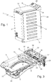
Figures 3 is a perspective view of the hopper assembly of the laundry washing machine shown inFigures 1 and2 , with parts removed for clarity's sake; -
Figures 4 is an enlarged and partly exploded perspective view of the hopper assembly shown inFigure 3 ; whereas -
Figures 5 is an enlarged side view of the hopper assembly shown inFigures 3 and4 , sectioned along the midplane of the washing machine and with parts exploded for clarity; whereas -
Figures 6 is an enlarged side view of the front portion of hopper assembly shown inFigure 5 , with parts removed for clarity's sake. - With reference to
Figures 1 and2 ,reference number 1 denotes as a whole a top-loadinglaundry washing machine 1 preferably suitable for domestic use. - The
laundry washing machine 1 firstly comprises: a preferably substantially parallelepiped-shaped, self-supportingboxlike casing 2 which is preferably made of metal and is structured for stably resting on the floor; a substantially vertically-oriented,hopper 3 which is incorporated into, or forms part of, the top wall ofcasing 2; and a preferably nearly barrel-shaped,washing tub 4 which, in use, contains the washing liquid, is arranged inside thecasing 2 beneath thehopper 3, and is superiorly provided with alarge access opening 5 that directly communicates with thesuperjacent hopper 3, preferably via an elastically-deformabletubular bellows 6 that preferably substantially watertight connects the access opening 5 ofwashing tub 4 to the lower mouth ofhopper 3. Thehopper 3 allows manual insertion and extraction of the laundry in/from thewashing tub 4. - In the example shown, in particular, the
washing tub 4 is preferably suspended in floating manner inside theboxlike casing 2 preferably via a suspension system that preferably comprises at least one and more conveniently a number ofcoil springs 7 connecting thewashing tub 4 to the upper part ofcasing 2, and at least one and more conveniently a number ofvibration dampers 8 connecting thewashing tub 2 to the bottom part ofcasing 2. - Preferably the
laundry washing machine 1 additionally comprises: a nearly cylindrical-shaped, hollowrotatable drum 9 with a water-permeable structure, which is structured for accommodating the laundry to be washed, and is stably fitted inside thewashing tub 4 with the capability of freely rotating about its, preferably substantially horizontally-oriented, central axis A which is optionally also substantially perpendicular to the midplane of thelaundry washing machine 1; and an electrically-poweredmotor assembly 10 which is preferably attached to thewashing tub 4, and is structured for driving into rotation therotatable drum 9 about central axis A, insidewashing tub 4. The laundry is inserted into and extracted from therotatable drum 9 via thehopper 3. - More in detail, the
rotatable drum 9 preferably has a substantially evenly-perforated cylindrical peripheral wall, and includes a manually-openable laundry loading-unloadinghatch 11 that is located on the cylindrical peripheral wall of the drum and is dimensioned to allow the user to easily manually put the laundry to be washed inside therotatable drum 9. - The electrically-powered
motor assembly 10, in turn, is preferably fastened underneath thewashing tub 4. - With reference to
Figures 1 and2 , preferably thelaundry washing machine 1 is moreover provided with a manually-openable,upper door 12 which is flag hinged to the top ofboxlike casing 2 so as to be able to rotate, preferably about a substantially horizontally-oriented reference axis B also locally perpendicular to the midplane of thelaundry washing machine 1, to and from a closing position (seeFigures 1 and2 ) in which theupper door 12 closes the upper mouth ofhopper 3 to seal thewashing tub 4 preferably substantially in watertight manner. - With reference to
Figures 2-5 , preferably thelaundry washing machine 1 additionally comprises: adetergent dispenser 13 which is located inside thecasing 2 and is structured for selectively feeding into the washing tub 4 a given amount of detergent, softener and/or other washing agent suitably mixed with the water arriving from the water mains; an electrically-operated,water supply circuit 14 which is located inside thecasing 2, is connectable to the water mains preferably via an external feeding pipe, and is suitably structured for selectively channelling the water of the water mains towards thedetergent dispenser 13 and/or directly towards thewashing tub 4; and optionally also an electrically-powered heating member 15 (namely a resistor) which is preferably located inside thewashing tub 4, and is adapted to selectively heat up the washing liquid contained into thewashing tub 4. - In the example shown, in particular, the
detergent dispenser 13 is preferably located inside thehopper 3, immediately underneath theupper door 12, so that the mixture of water and detergent, softener and/or other washing agent is allowed to freely drop by gravity into the beneath-locatedwashing tub 4. - Additionally the
detergent dispenser 13 is preferably attached in manually-removable manner to a lateral wall ofhopper 3. - More in detail, in the example shown the
detergent dispenser 13 is preferably fitted/recessed in manually-removable manner into a corresponding and roughly complementary-shaped concave seat orrecess 16 specifically formed on the rear wall ofhopper 3, preferably next to the hinge/s 17 connecting theupper door 12 to the top wall ofcasing 2. - The
water supply circuit 14, in turn, preferably comprises: at least one and more conveniently a plurality ofsolenoid valves 18 that are preferably located adjacent to the rear wall ofcasing 2, preferably substantially horizontally aligned thehopper 3, and are preferably connected to acommon manifold 19 that preferably receives the water of the water mains from the aforesaid external feeding pipe; and preferably a corresponding number ofconnection pipes 20 each of which connects arespective solenoid valve 18 to thedetergent dispenser 13 and/or to thewashing tub 4. - Furthermore, in the example shown the common water-
distribution manifold 19, the solenoid valve/s 18 and the corresponding connection pipe/s 20 are preferably located inside a substantially basin-shaped container 22 which is fixed to the rear wall ofcasing 2, beside thehopper 3. - Preferably the substantially basin-
shaped container 22 is furthermore made in one piece with theadjacent hopper 3. - In other words, the
hopper 3 and the substantially basin-shaped container 22 preferably form a monolithic structure and theupper door 12 is preferably hinged to said monolithic structure. - More in detail,
hopper 3 and the adjacent, substantially basin-shaped container 22 are preferably permanently connected by arigid bridge portion 23, and the hinge/s 17 connecting theupper door 12 to the top wall ofcasing 2, or rather to the monolithic structure formed by thehopper 3 and the basin-shaped container 22, is/are preferably located on saidbridge portion 23. - Preferably said monolithic
structure incorporating hopper 3 andcontainer 22 is furthermore made of plastic material, preferably via an injection molding process. - With particular reference to
Figures 1 and2 , preferably the rear wall ofcasing 2 moreover has, spaced beneath the solenoid valve/s 18 - or rather the basin-shaped container 22 accommodating the solenoid valve/s 18 -, a huge outwards bulgingportion 24 which is substantially horizontally aligned to thewashing tub 4 and therotatable drum 9, and which optionally also substantially copies the rounded profile of the side ofwashing tub 4. - The
heating member 15, in turn, is preferably located within a tray-shaped portion 26 formed on the bottom ofwashing tub 4, so as to be submerged by the washing liquid. Theheating member 15 is therefore arranged spaced above themotor assembly 10. - With reference to
Figures 3-6 , thehopper 3 additionally includes anoverflow assembly 30 which is located/incorporated on a sidewall of thesame hopper 3, and is specifically structured for immediately draining the exceeding water out ofhopper 3 and straight down to the bottom ofcasing 2. Theoverflow assembly 30 is additionally structured to minimize the noise coming out ofwashing tub 4 via thesame overflow assembly 30 when thelaundry washing machine 1 operates. - More in detail, the
overflow assembly 30 is preferably located on thefront sidewall 31 ofhopper 3, so as to face the adjacent and nearly vertical, front wall ofcasing 2. - Preferably the
overflow assembly 30 is furthermore structured to channel the exceeding water coming out ofhopper 3 up to the immediately facing, front wall ofcasing 2, so as to force said water to flow downwards by gravity along the same front wall ofcasing 2. - More in detail, with particular reference to
Figures 5 and6 , thehopper 3 is preferably provided with a large, upwards-extending and preferably also nearly reverse-L shaped,overflow duct 32 which is integrally formed with thefront sidewall 31 ofhopper 3, so that thelower mouth 32a of theoverflow duct 32 is located roughly on the perimeter edge/rim of the lower mouth ofhopper 3 and that theupper mouth 32b of theoverflow duct 32 is located on the outer face of thefront sidewall 31 ofhopper 3, spaced above the lower mouth ofhopper 3. - The
overflow assembly 30 furthermore includes: an outwards-extending and preferably substantially horizontally-oriented,tubular member 33 which is associated/ fitted into theupper mouth 32b of theoverflow duct 32 so as jut out from thefront sidewall 31 ofhopper 3 towards the immediately facing, front wall ofcasing 2, while forming an extension of theoverflow duct 32 and preferably also while remaining substantially perpendicular to the same front wall ofcasing 2; and preferably also a hidingmember 34, which is inserted/plugged into thelower mouth 32a of theoverflow duct 32 so as to hide the same lower mouth, and is provided with a number of waterways allowing the exceeding water to freely enter into theoverflow duct 32 bypassing at once thesame hiding member 34. - More in detail, the
tubular member 33 is preferably fitted into theupper mouth 32b ofoverflow duct 32 in substantially watertight manner, preferably by welding or by known connection devices eventually associated to sealing methods/devices, and is preferably also dimensioned so as to reach/touch the immediately facing, front wall ofcasing 2, for channelling the exceeding water up to the immediately facing, nearly-vertical front wall ofcasing 2. - Preferably the
tubular member 33 is furthermore roughly S-shaped so to form a substantially siphon-like extension of theoverflow duct 32. - More specifically, the
tubular member 33 is preferably S-shaped so that the outlet mouth of thetubular member 33 is nearly horizontally aligned to theupper mouth 32b ofoverflow duct 32. - In the example shown, in particular, the
lower mouth 32a ofoverflow duct 32 is preferably straight and oblong in shape, whereas theupper mouth 32b ofoverflow duct 32 is preferably substantially rectangular in shape and optionally also wider than thelower mouth 32a. - Preferably the
overflow duct 32 is furthermore divided into a first and a second consecutive segments. The first segment is nearly rectilinear and extends roughly upwards inside thefront sidewall 31 ofhopper 3, starting from the perimeter edge/rim of the lower mouth ofhopper 3. The second segment, in turn, is nearly rectilinear and is inclined with respect to the first segment by an angle preferably slightly lower than 90°, so as to be slightly slopped downwards. - More specifically, the second segment of
overflow duct 32 is inclined with respect to the vertical by an angle preferably ranging between 70° and 80°. - With particular reference to
Figures 4 ,5 and6 , the hidingmember 34, on the other hand, has a water-permeable structure, is preferably almost completely fitted/ recessed into the first segment of theoverflow duct 32, and is preferably firmly locked to the body ofhopper 3 via a snap-lock fastening system. - More in detail, the hiding
member 34 preferably has a substantially rectangular and tray-shaped structure, and is fitted into the first segment ofoverflow duct 32 so that afirst segment 35 of its raised perimeter edge is preferably roughly flush with thelower mouth 32a ofoverflow duct 32. Moreover the hidingmember 34 is preferably fitted into the first segment ofoverflow duct 32 so that asecond segment 36 of its raised perimeter edge, opposite to saidfirst segment 35, is arranged inside theoverflow duct 32 spaced above the elbow/bend connecting the first and second consecutive segments of theoverflow duct 32. - Preferably the bottom wall of the substantially tray-shaped
hiding member 34 moreover has a number of large pass-through openings allowing the exceeding water to easily reach the second downwards-slopped segment of theoverflow duct 32. - Furthermore, the bottom wall of the substantially tray-shaped, hiding
member 34 is preferably additionally provided with a cantilever snap-fit tab 37 adapted to snap on a sharp edge at the elbow/bend connecting the first and second consecutive segments of theoverflow duct 32. - Finally, in the examples shown, the substantially tray-shaped water-
permeable hiding member 34 is preferably made of plastic material, preferably via an injection molding process. - With particular reference to
Figures 4 and6 , thetubular member 33, in turn, has a substantially rectangular cross-section, locally complementary to that of theupper mouth 32b ofoverflow duct 32, or rather of the second segment ofoverflow duct 32, so as to be telescopically fitted into the second segment ofoverflow duct 32. - Moreover, the outlet mouth of
tubular member 33 is preferably provided with a plate-like protruding lip orflap 38 that preferably has a flexible and/or roughly comb-shaped structure, and is dimensioned to abut against the inner face of the facing, nearly vertical, front wall ofcasing 2, so as to channel the water coming out from theupper mouth 32b ofoverflow duct 32 up to the immediately facing, nearly vertical front wall ofcasing 2. Preferably the plate-like protrudingflap 38 is furthermore slightly slopped downwards. - Finally, in the examples shown, the nearly S-shaped
tubular member 33 is preferably made of plastic material, preferably via an injection molding process. - With reference to
Figures 1 and2 , preferably thelaundry washing machine 1 additionally comprises anelectronic control unit 27 which is located inside thecasing 2 and which preferably controls themotor assembly 10 and/or thewater supply circuit 14 and/or theheating member 15, so as to perform the washing cycle manually-selected by the user via anappliance control panel 28 which, in turn, is preferably located/incorporated on the top wall ofcasing 2, preferably above the solenoid valve/s 18 ofwater supply circuit 14. - Preferably the
laundry washing machine 1 finally includes an aqua-stop safety system 40 which is adapted to channel the water mains to thewater supply circuit 14. - The aqua-
stop safety system 40 preferably comprises: a longflexible hosepipe 41 having the proximal end in direct communication with thewater supply circuit 14, or rather with the water-distribution manifold 19 ofwater supply circuit 14, and the distal end suitably structured to watertight couple, preferably in manually detachable manner, with the tap of the water mains; and a normally-closed, auxiliary solenoid valve (not shown) which is located at the distal end of thehosepipe 41 for directly controlling the entry of water into thesame hosepipe 41. Therefore the fresh water of the water mains can enter within and flow along thehosepipe 41 towards the solenoid valve/s 18 ofwater supply circuit 14 solely when the auxiliary solenoid valve is in the open position. - The normally-closed, auxiliary solenoid valve is preferably directly controlled by the
electronic control unit 27 on the basis of awater presence sensor 43 which is capable of detecting the presence of water and is preferably located on the bottom ofcasing 2 where the water dropping fromtubular member 33 accumulates. - Operation of
laundry washing machine 1 is almost identical to that of any other top-loading home laundry washing machine and therefore does not require further explanations. - The
overflow assembly 30 ofhopper 3, in turn, is capable of quickly and silently draining the exceeding water out ofwashing tub 4. - More in detail, in case a
solenoid valve 18 gets stuck in the open position, the level of water inside thewashing tub 4 start rising up to reach the height of the bend of the roughly S-shapedtubular member 33. Then the exceeding water starts flowing along thetubular member 33, up to the immediately facing and nearly vertical, front wall ofcasing 2. - When arrives to the inner face of the front wall of
casing 2, the exceeding water starts flowing downwards on surface of the front wall ofcasing 2, up to the bottom ofcasing 2 where it starts accumulating until thewater presence sensor 43 detects the presence of water and immediately stops powering the normally-closed, auxiliary solenoid valve. Deactivation of the auxiliary solenoid valve, in turn, interrupts the flow of fresh water into thewashing tub 4. - The extension of
tubular member 33 up to touch the inner face of the nearly-vertical front ofcasing 2 prevents the exceeding water from freely dropping/falling down to the bottom ofcasing 2, thus avoiding the noise of the water droplets violently bumping against the bottom wall ofcasing 2. - The comb-shaped plate-like protruding lip or
flap 38, in turn, spreads the water coming out fromtubular member 33 on a large portion of the inner face of the front wall ofcasing 2. - The L-form of the
overflow duct 32 and the hidingmember 34, finally, reduces the propagation of the washing noise up to thetubular member 33. - The advantages resulting from the particular structure of the
overflow assembly 30 are remarkable. - First of all, due to the particular shape of both
overflow duct 32 andtubular member 33, theoverflow assembly 30 is capable of quickly draining the exceeding water out ofwashing tub 4 while efficiently preventing, at same time, the washing noise from coming out ofwashing tub 4. - Moreover the
lower mouth 32a ofoverflow duct 32 is located on the perimeter edge/rim of the lower mouth ofhopper 3 where it totally hidden from view. - Clearly changes and modifications may be made to the
laundry washing machine 1 without, however, departing from the scope of the present invention. - For example, according to a first, non-shown alternative embodiment the
overflow duct 32 is integrally formed with a lateral sidewall ofhopper 3. The nearly S-shaped,tubular member 33, in turn, juts out from the same lateral sidewall ofhopper 3 towards the immediately facing and nearly vertical, lateral wall ofboxlike casing 2, preferably so as to reach/touch the same lateral wall ofcasing 2. - According to a second, non-shown and less-sophisticated alternative embodiment, the upwards-extending and preferably also nearly reverse-L-shaped,
overflow duct 32, rather than being incorporated into the front or lateral sidewall ofhopper 3, is at least partially formed/incorporated on a separate piece which is firmly attached/coupled to the sidewall ofhopper 3. - According to a third, non-shown alternative embodiment, moreover, the hiding
element 34 can be integrally formed on theoverflow duct 32, with a shape suitable to create a sort of water barrier toward the bottom side of the machine, and allowing at the same time the free passage of water in case of the water reaching the overflow level. Accordingly, the alternative shape of hidingelement 34, preferably integrated in theoutflow duct 32, will be adapted to the constraints of the manufacturing process, eventually requiring modifications departing from the shape of the element depicted inFigures 4 ,5 and6 .
Claims (15)
- A laundry washing machine (1) comprising: a boxlike casing (2) structured for resting on the floor; a vertically-oriented, hopper (3) which is located on a top wall of said casing (2); a washing tub (4) which is arranged inside the casing (2) beneath the hopper (3), and is superiorly provided with an access opening (5) that directly communicates with a lower mouth of the hopper (3) for allowing insertion and extraction of the laundry in/from the washing tub (4) via said hopper (3); and an overflow assembly (30) for draining out of the hopper (3) the exceeding water;
the laundry washing machine (1) being characterized in that said overflow assembly (30) comprises: an upwards-extending overflow duct (32) which is located on a sidewall (31) of said hopper (3), so that a lower mouth (32a) of the overflow duct (32) is located roughly on the perimeter edge/rim of the lower mouth of the hopper (3) and that an upper mouth (32b) of the overflow duct (32) is located on the outer face of the same sidewall (31) of the hopper (3), spaced above the lower mouth of hopper (3); and an outwards-extending, tubular member (33) which is associated to the upper mouth (32b) of the overflow duct (32) so as protrude from the sidewall (31) of the hopper (3) towards the facing wall of the casing (2), forming an extension of said overflow duct (32). - Laundry washing machine according to Claim 1, wherein the overflow duct (32) is substantially reversed-L shaped.
- Laundry washing machine according to Claim 1 or 2, wherein the tubular member (33) is roughly S-shaped so as to form a siphon-like extension of said overflow duct (32).
- Laundry washing machine according to any one of the preceding claims, wherein the tubular member (33) extends substantially horizontally.
- Laundry washing machine according to any one of the preceding claims, wherein the outlet mouth of the tubular member (33) is nearly horizontally aligned to the upper mouth (32b) of the overflow duct (32).
- Laundry washing machine according to any one of the preceding claims, wherein the tubular member (33) is dimensioned so as to reach/touch the facing upright wall of the casing (2), for channelling the exceeding water up to the same upright wall of the casing (2).
- Laundry washing machine according to Claim 6, wherein the outlet mouth of the tubular member (33) has a plate-like protruding lip/flap (38) which is dimensioned to abut against the inner face of the facing upright wall of said casing (2).
- Laundry washing machine according to Claim 7, wherein said plate-like protruding lip/flap (38) has a comb-shaped structure.
- Laundry washing machine according to Claim 7 or 8, wherein said plate-like protruding lip/flap (38) is slopped downwards.
- Laundry washing machine according to any one of the preceding claims, wherein said overflow assembly (30) additionally comprises a hiding member (34) which is located in the lower mouth (32a) of the overflow duct (32) so as to hide the same lower mouth, and is provided with a number of waterways allowing the exceeding water to freely enter into the overflow duct (32) bypassing at once the same hiding member (34).
- Laundry washing machine according to Claim 10, wherein the hiding member (34) is almost completely fitted/recessed into a starting segment of the overflow duct (32) and/or is firmly locked to the body of the hopper (3) via a snap-lock fastening system (37).
- Laundry washing machine according to Claim 11, wherein the hiding member (34) has a substantially rectangular and tray-shaped structure, and is fitted into the overflow duct (32) so that a first segment (35) of its raised perimeter edge is roughly flush with the lower mouth (32a) of overflow duct (32).
- Laundry washing machine according to Claim 12, wherein the hiding member (34) is fitted into the overflow duct (32) so that a second segment (36) of its raised perimeter edge, opposite to said first segment (35), is arranged inside the overflow duct (32) spaced above an elbow/bend of said overflow duct (32).
- Laundry washing machine according to any one of Claims 2-13, wherein the overflow duct (32) is divided into a first and a second consecutive segments; the first segment being nearly rectilinear and extending upwards inside the sidewall (31) of the hopper (3), starting from the perimeter edge/rim of the lower mouth of the hopper (3); the second segment being nearly rectilinear and being inclined with respect to the first segment by an angle lower than 90°.
- Laundry washing machine according to any one of the preceding claims, wherein said overflow assembly (30) is located on the sidewall (31) directly faced to a nearly vertical front wall of the casing (2).
Priority Applications (2)
| Application Number | Priority Date | Filing Date | Title |
|---|---|---|---|
| EP19167598.2A EP3719195B1 (en) | 2019-04-05 | 2019-04-05 | Top-loading laundry washing machine |
| PL19167598T PL3719195T3 (en) | 2019-04-05 | 2019-04-05 | Top-loading laundry washing machine |
Applications Claiming Priority (1)
| Application Number | Priority Date | Filing Date | Title |
|---|---|---|---|
| EP19167598.2A EP3719195B1 (en) | 2019-04-05 | 2019-04-05 | Top-loading laundry washing machine |
Publications (2)
| Publication Number | Publication Date |
|---|---|
| EP3719195A1 true EP3719195A1 (en) | 2020-10-07 |
| EP3719195B1 EP3719195B1 (en) | 2021-09-22 |
Family
ID=66101956
Family Applications (1)
| Application Number | Title | Priority Date | Filing Date |
|---|---|---|---|
| EP19167598.2A Active EP3719195B1 (en) | 2019-04-05 | 2019-04-05 | Top-loading laundry washing machine |
Country Status (2)
| Country | Link |
|---|---|
| EP (1) | EP3719195B1 (en) |
| PL (1) | PL3719195T3 (en) |
Citations (3)
| Publication number | Priority date | Publication date | Assignee | Title |
|---|---|---|---|---|
| US3608339A (en) * | 1968-10-02 | 1971-09-28 | Zanussi A Spa Industrie | Antifoam seal for washing machines |
| KR20030055970A (en) * | 2001-12-27 | 2003-07-04 | 주식회사 엘지이아이 | Over flow structure for washing machine |
| EP3354786A1 (en) * | 2016-02-29 | 2018-08-01 | Qingdao Haier Washing Machine Co., Ltd. | Washing machine |
-
2019
- 2019-04-05 EP EP19167598.2A patent/EP3719195B1/en active Active
- 2019-04-05 PL PL19167598T patent/PL3719195T3/en unknown
Patent Citations (3)
| Publication number | Priority date | Publication date | Assignee | Title |
|---|---|---|---|---|
| US3608339A (en) * | 1968-10-02 | 1971-09-28 | Zanussi A Spa Industrie | Antifoam seal for washing machines |
| KR20030055970A (en) * | 2001-12-27 | 2003-07-04 | 주식회사 엘지이아이 | Over flow structure for washing machine |
| EP3354786A1 (en) * | 2016-02-29 | 2018-08-01 | Qingdao Haier Washing Machine Co., Ltd. | Washing machine |
Also Published As
| Publication number | Publication date |
|---|---|
| PL3719195T3 (en) | 2022-02-07 |
| EP3719195B1 (en) | 2021-09-22 |
Similar Documents
| Publication | Publication Date | Title |
|---|---|---|
| US8931310B2 (en) | Bulk dispensing system for washing machine | |
| US20050229652A1 (en) | Apparatus for supplying detergent in washer | |
| US4168615A (en) | Clothes washing machine with water recirculation | |
| EP2959050B1 (en) | Laundry washing machine | |
| EP0655523A1 (en) | Front loading washing machine | |
| US9970147B2 (en) | Laundry washing machine | |
| US5582039A (en) | Integrated tub ring with clothes diverter | |
| US8844325B2 (en) | Liquid additive dispensing apparatus for a washing machine | |
| EP3540113A1 (en) | Clothes-treatment apparatus and method for controlling clothes-treatment apparatus | |
| EP3433410A1 (en) | Laundry washing machine comprising a water softening device and a local electronic control unit | |
| JP2022190019A (en) | washing machine | |
| US11066775B2 (en) | Method and apparatus for cleaning laundry | |
| US3039286A (en) | Drain overflow arrangement for built-in washing machine | |
| EP3719195B1 (en) | Top-loading laundry washing machine | |
| KR20080078517A (en) | washer | |
| US12180641B2 (en) | Laundry washing machine | |
| EP2865801A1 (en) | Laundry washing machine comprising a detergent dispensing assembly | |
| AU2018395018B2 (en) | Laundry processing device | |
| CN111519398A (en) | A kind of drum washing machine and method for putting detergent | |
| US3798932A (en) | Siphoned vortex liquid dispenser for automatic washers | |
| EP2889418B1 (en) | Washing machine | |
| KR20180067594A (en) | Laundry Dryer | |
| WO2020088286A1 (en) | Laundry detergent box and washing machine | |
| KR102423575B1 (en) | Washing machine | |
| JP4667159B2 (en) | Washing and drying machine |
Legal Events
| Date | Code | Title | Description |
|---|---|---|---|
| PUAI | Public reference made under article 153(3) epc to a published international application that has entered the european phase |
Free format text: ORIGINAL CODE: 0009012 |
|
| STAA | Information on the status of an ep patent application or granted ep patent |
Free format text: STATUS: THE APPLICATION HAS BEEN PUBLISHED |
|
| AK | Designated contracting states |
Kind code of ref document: A1 Designated state(s): AL AT BE BG CH CY CZ DE DK EE ES FI FR GB GR HR HU IE IS IT LI LT LU LV MC MK MT NL NO PL PT RO RS SE SI SK SM TR |
|
| AX | Request for extension of the european patent |
Extension state: BA ME |
|
| STAA | Information on the status of an ep patent application or granted ep patent |
Free format text: STATUS: REQUEST FOR EXAMINATION WAS MADE |
|
| 17P | Request for examination filed |
Effective date: 20210407 |
|
| RBV | Designated contracting states (corrected) |
Designated state(s): AL AT BE BG CH CY CZ DE DK EE ES FI FR GB GR HR HU IE IS IT LI LT LU LV MC MK MT NL NO PL PT RO RS SE SI SK SM TR |
|
| GRAP | Despatch of communication of intention to grant a patent |
Free format text: ORIGINAL CODE: EPIDOSNIGR1 |
|
| RIC1 | Information provided on ipc code assigned before grant |
Ipc: D06F 39/08 20060101ALN20210518BHEP Ipc: D06F 39/12 20060101AFI20210518BHEP |
|
| STAA | Information on the status of an ep patent application or granted ep patent |
Free format text: STATUS: GRANT OF PATENT IS INTENDED |
|
| INTG | Intention to grant announced |
Effective date: 20210624 |
|
| GRAS | Grant fee paid |
Free format text: ORIGINAL CODE: EPIDOSNIGR3 |
|
| GRAA | (expected) grant |
Free format text: ORIGINAL CODE: 0009210 |
|
| STAA | Information on the status of an ep patent application or granted ep patent |
Free format text: STATUS: THE PATENT HAS BEEN GRANTED |
|
| AK | Designated contracting states |
Kind code of ref document: B1 Designated state(s): AL AT BE BG CH CY CZ DE DK EE ES FI FR GB GR HR HU IE IS IT LI LT LU LV MC MK MT NL NO PL PT RO RS SE SI SK SM TR |
|
| REG | Reference to a national code |
Ref country code: GB Ref legal event code: FG4D |
|
| REG | Reference to a national code |
Ref country code: IE Ref legal event code: FG4D |
|
| REG | Reference to a national code |
Ref country code: DE Ref legal event code: R096 Ref document number: 602019007782 Country of ref document: DE |
|
| REG | Reference to a national code |
Ref country code: CH Ref legal event code: EP Ref country code: AT Ref legal event code: REF Ref document number: 1432418 Country of ref document: AT Kind code of ref document: T Effective date: 20211015 |
|
| REG | Reference to a national code |
Ref country code: LT Ref legal event code: MG9D |
|
| REG | Reference to a national code |
Ref country code: NL Ref legal event code: MP Effective date: 20210922 |
|
| PG25 | Lapsed in a contracting state [announced via postgrant information from national office to epo] |
Ref country code: LT Free format text: LAPSE BECAUSE OF FAILURE TO SUBMIT A TRANSLATION OF THE DESCRIPTION OR TO PAY THE FEE WITHIN THE PRESCRIBED TIME-LIMIT Effective date: 20210922 Ref country code: BG Free format text: LAPSE BECAUSE OF FAILURE TO SUBMIT A TRANSLATION OF THE DESCRIPTION OR TO PAY THE FEE WITHIN THE PRESCRIBED TIME-LIMIT Effective date: 20211222 Ref country code: NO Free format text: LAPSE BECAUSE OF FAILURE TO SUBMIT A TRANSLATION OF THE DESCRIPTION OR TO PAY THE FEE WITHIN THE PRESCRIBED TIME-LIMIT Effective date: 20211222 Ref country code: HR Free format text: LAPSE BECAUSE OF FAILURE TO SUBMIT A TRANSLATION OF THE DESCRIPTION OR TO PAY THE FEE WITHIN THE PRESCRIBED TIME-LIMIT Effective date: 20210922 Ref country code: SE Free format text: LAPSE BECAUSE OF FAILURE TO SUBMIT A TRANSLATION OF THE DESCRIPTION OR TO PAY THE FEE WITHIN THE PRESCRIBED TIME-LIMIT Effective date: 20210922 Ref country code: RS Free format text: LAPSE BECAUSE OF FAILURE TO SUBMIT A TRANSLATION OF THE DESCRIPTION OR TO PAY THE FEE WITHIN THE PRESCRIBED TIME-LIMIT Effective date: 20210922 Ref country code: FI Free format text: LAPSE BECAUSE OF FAILURE TO SUBMIT A TRANSLATION OF THE DESCRIPTION OR TO PAY THE FEE WITHIN THE PRESCRIBED TIME-LIMIT Effective date: 20210922 |
|
| REG | Reference to a national code |
Ref country code: AT Ref legal event code: MK05 Ref document number: 1432418 Country of ref document: AT Kind code of ref document: T Effective date: 20210922 |
|
| PG25 | Lapsed in a contracting state [announced via postgrant information from national office to epo] |
Ref country code: LV Free format text: LAPSE BECAUSE OF FAILURE TO SUBMIT A TRANSLATION OF THE DESCRIPTION OR TO PAY THE FEE WITHIN THE PRESCRIBED TIME-LIMIT Effective date: 20210922 Ref country code: GR Free format text: LAPSE BECAUSE OF FAILURE TO SUBMIT A TRANSLATION OF THE DESCRIPTION OR TO PAY THE FEE WITHIN THE PRESCRIBED TIME-LIMIT Effective date: 20211223 |
|
| PG25 | Lapsed in a contracting state [announced via postgrant information from national office to epo] |
Ref country code: AT Free format text: LAPSE BECAUSE OF FAILURE TO SUBMIT A TRANSLATION OF THE DESCRIPTION OR TO PAY THE FEE WITHIN THE PRESCRIBED TIME-LIMIT Effective date: 20210922 |
|
| PG25 | Lapsed in a contracting state [announced via postgrant information from national office to epo] |
Ref country code: IS Free format text: LAPSE BECAUSE OF FAILURE TO SUBMIT A TRANSLATION OF THE DESCRIPTION OR TO PAY THE FEE WITHIN THE PRESCRIBED TIME-LIMIT Effective date: 20220122 Ref country code: SK Free format text: LAPSE BECAUSE OF FAILURE TO SUBMIT A TRANSLATION OF THE DESCRIPTION OR TO PAY THE FEE WITHIN THE PRESCRIBED TIME-LIMIT Effective date: 20210922 Ref country code: RO Free format text: LAPSE BECAUSE OF FAILURE TO SUBMIT A TRANSLATION OF THE DESCRIPTION OR TO PAY THE FEE WITHIN THE PRESCRIBED TIME-LIMIT Effective date: 20210922 Ref country code: PT Free format text: LAPSE BECAUSE OF FAILURE TO SUBMIT A TRANSLATION OF THE DESCRIPTION OR TO PAY THE FEE WITHIN THE PRESCRIBED TIME-LIMIT Effective date: 20220124 Ref country code: NL Free format text: LAPSE BECAUSE OF FAILURE TO SUBMIT A TRANSLATION OF THE DESCRIPTION OR TO PAY THE FEE WITHIN THE PRESCRIBED TIME-LIMIT Effective date: 20210922 Ref country code: ES Free format text: LAPSE BECAUSE OF FAILURE TO SUBMIT A TRANSLATION OF THE DESCRIPTION OR TO PAY THE FEE WITHIN THE PRESCRIBED TIME-LIMIT Effective date: 20210922 Ref country code: EE Free format text: LAPSE BECAUSE OF FAILURE TO SUBMIT A TRANSLATION OF THE DESCRIPTION OR TO PAY THE FEE WITHIN THE PRESCRIBED TIME-LIMIT Effective date: 20210922 Ref country code: CZ Free format text: LAPSE BECAUSE OF FAILURE TO SUBMIT A TRANSLATION OF THE DESCRIPTION OR TO PAY THE FEE WITHIN THE PRESCRIBED TIME-LIMIT Effective date: 20210922 Ref country code: AL Free format text: LAPSE BECAUSE OF FAILURE TO SUBMIT A TRANSLATION OF THE DESCRIPTION OR TO PAY THE FEE WITHIN THE PRESCRIBED TIME-LIMIT Effective date: 20210922 |
|
| REG | Reference to a national code |
Ref country code: DE Ref legal event code: R097 Ref document number: 602019007782 Country of ref document: DE |
|
| PG25 | Lapsed in a contracting state [announced via postgrant information from national office to epo] |
Ref country code: DK Free format text: LAPSE BECAUSE OF FAILURE TO SUBMIT A TRANSLATION OF THE DESCRIPTION OR TO PAY THE FEE WITHIN THE PRESCRIBED TIME-LIMIT Effective date: 20210922 |
|
| PLBE | No opposition filed within time limit |
Free format text: ORIGINAL CODE: 0009261 |
|
| STAA | Information on the status of an ep patent application or granted ep patent |
Free format text: STATUS: NO OPPOSITION FILED WITHIN TIME LIMIT |
|
| 26N | No opposition filed |
Effective date: 20220623 |
|
| PG25 | Lapsed in a contracting state [announced via postgrant information from national office to epo] |
Ref country code: SI Free format text: LAPSE BECAUSE OF FAILURE TO SUBMIT A TRANSLATION OF THE DESCRIPTION OR TO PAY THE FEE WITHIN THE PRESCRIBED TIME-LIMIT Effective date: 20210922 |
|
| REG | Reference to a national code |
Ref country code: CH Ref legal event code: PL |
|
| REG | Reference to a national code |
Ref country code: BE Ref legal event code: MM Effective date: 20220430 |
|
| PG25 | Lapsed in a contracting state [announced via postgrant information from national office to epo] |
Ref country code: MC Free format text: LAPSE BECAUSE OF FAILURE TO SUBMIT A TRANSLATION OF THE DESCRIPTION OR TO PAY THE FEE WITHIN THE PRESCRIBED TIME-LIMIT Effective date: 20210922 Ref country code: LU Free format text: LAPSE BECAUSE OF NON-PAYMENT OF DUE FEES Effective date: 20220405 Ref country code: LI Free format text: LAPSE BECAUSE OF NON-PAYMENT OF DUE FEES Effective date: 20220430 Ref country code: FR Free format text: LAPSE BECAUSE OF NON-PAYMENT OF DUE FEES Effective date: 20220430 Ref country code: CH Free format text: LAPSE BECAUSE OF NON-PAYMENT OF DUE FEES Effective date: 20220430 |
|
| PG25 | Lapsed in a contracting state [announced via postgrant information from national office to epo] |
Ref country code: BE Free format text: LAPSE BECAUSE OF NON-PAYMENT OF DUE FEES Effective date: 20220430 |
|
| PG25 | Lapsed in a contracting state [announced via postgrant information from national office to epo] |
Ref country code: IE Free format text: LAPSE BECAUSE OF NON-PAYMENT OF DUE FEES Effective date: 20220405 |
|
| P01 | Opt-out of the competence of the unified patent court (upc) registered |
Effective date: 20230625 |
|
| GBPC | Gb: european patent ceased through non-payment of renewal fee |
Effective date: 20230405 |
|
| PG25 | Lapsed in a contracting state [announced via postgrant information from national office to epo] |
Ref country code: GB Free format text: LAPSE BECAUSE OF NON-PAYMENT OF DUE FEES Effective date: 20230405 |
|
| PG25 | Lapsed in a contracting state [announced via postgrant information from national office to epo] |
Ref country code: GB Free format text: LAPSE BECAUSE OF NON-PAYMENT OF DUE FEES Effective date: 20230405 |
|
| PG25 | Lapsed in a contracting state [announced via postgrant information from national office to epo] |
Ref country code: SM Free format text: LAPSE BECAUSE OF FAILURE TO SUBMIT A TRANSLATION OF THE DESCRIPTION OR TO PAY THE FEE WITHIN THE PRESCRIBED TIME-LIMIT Effective date: 20210922 Ref country code: MK Free format text: LAPSE BECAUSE OF FAILURE TO SUBMIT A TRANSLATION OF THE DESCRIPTION OR TO PAY THE FEE WITHIN THE PRESCRIBED TIME-LIMIT Effective date: 20210922 Ref country code: CY Free format text: LAPSE BECAUSE OF FAILURE TO SUBMIT A TRANSLATION OF THE DESCRIPTION OR TO PAY THE FEE WITHIN THE PRESCRIBED TIME-LIMIT Effective date: 20210922 |
|
| PG25 | Lapsed in a contracting state [announced via postgrant information from national office to epo] |
Ref country code: HU Free format text: LAPSE BECAUSE OF FAILURE TO SUBMIT A TRANSLATION OF THE DESCRIPTION OR TO PAY THE FEE WITHIN THE PRESCRIBED TIME-LIMIT; INVALID AB INITIO Effective date: 20190405 |
|
| PG25 | Lapsed in a contracting state [announced via postgrant information from national office to epo] |
Ref country code: TR Free format text: LAPSE BECAUSE OF FAILURE TO SUBMIT A TRANSLATION OF THE DESCRIPTION OR TO PAY THE FEE WITHIN THE PRESCRIBED TIME-LIMIT Effective date: 20210922 |
|
| PG25 | Lapsed in a contracting state [announced via postgrant information from national office to epo] |
Ref country code: MT Free format text: LAPSE BECAUSE OF FAILURE TO SUBMIT A TRANSLATION OF THE DESCRIPTION OR TO PAY THE FEE WITHIN THE PRESCRIBED TIME-LIMIT Effective date: 20210922 |
|
| PGFP | Annual fee paid to national office [announced via postgrant information from national office to epo] |
Ref country code: DE Payment date: 20250428 Year of fee payment: 7 |
|
| PGFP | Annual fee paid to national office [announced via postgrant information from national office to epo] |
Ref country code: IT Payment date: 20250422 Year of fee payment: 7 |
|
| PGFP | Annual fee paid to national office [announced via postgrant information from national office to epo] |
Ref country code: PL Payment date: 20260324 Year of fee payment: 8 |