EP3719180A1 - Apparatus and method for electrochemically isolating a section of a substrate - Google Patents
Apparatus and method for electrochemically isolating a section of a substrate Download PDFInfo
- Publication number
- EP3719180A1 EP3719180A1 EP19167228.6A EP19167228A EP3719180A1 EP 3719180 A1 EP3719180 A1 EP 3719180A1 EP 19167228 A EP19167228 A EP 19167228A EP 3719180 A1 EP3719180 A1 EP 3719180A1
- Authority
- EP
- European Patent Office
- Prior art keywords
- adjustment
- segments
- isolation
- substrate
- segment
- Prior art date
- Legal status (The legal status is an assumption and is not a legal conclusion. Google has not performed a legal analysis and makes no representation as to the accuracy of the status listed.)
- Withdrawn
Links
Images


Classifications
-
- C—CHEMISTRY; METALLURGY
- C25—ELECTROLYTIC OR ELECTROPHORETIC PROCESSES; APPARATUS THEREFOR
- C25D—PROCESSES FOR THE ELECTROLYTIC OR ELECTROPHORETIC PRODUCTION OF COATINGS; ELECTROFORMING; APPARATUS THEREFOR
- C25D7/00—Electroplating characterised by the article coated
- C25D7/04—Tubes; Rings; Hollow bodies
-
- C—CHEMISTRY; METALLURGY
- C25—ELECTROLYTIC OR ELECTROPHORETIC PROCESSES; APPARATUS THEREFOR
- C25D—PROCESSES FOR THE ELECTROLYTIC OR ELECTROPHORETIC PRODUCTION OF COATINGS; ELECTROFORMING; APPARATUS THEREFOR
- C25D17/00—Constructional parts, or assemblies thereof, of cells for electrolytic coating
- C25D17/008—Current shielding devices
-
- C—CHEMISTRY; METALLURGY
- C25—ELECTROLYTIC OR ELECTROPHORETIC PROCESSES; APPARATUS THEREFOR
- C25D—PROCESSES FOR THE ELECTROLYTIC OR ELECTROPHORETIC PRODUCTION OF COATINGS; ELECTROFORMING; APPARATUS THEREFOR
- C25D5/00—Electroplating characterised by the process; Pretreatment or after-treatment of workpieces
- C25D5/02—Electroplating of selected surface areas
- C25D5/022—Electroplating of selected surface areas using masking means
Definitions
- This invention relates to an adjustable isolation apparatus for an electrochemical treatment apparatus in order to isolate a section of an elongated substrate in a direction of isolation of the isolating apparatus such that a significant electrochemical treatment of the isolated section by an electrochemically active liquid is preventable, wherein the substrate has a direction of isolation along which the section is isolated from another region of the substrate; an electrochemical treatment apparatus comprising the adjustable isolation apparatus and a method to adjust the adjustable isolation apparatus for an electrochemical treatment apparatus.
- rods Plants for electrochemical pickling, galvanizing and/or electrochemical cleaning of elongated objects, particularly round rods, are well known in the art. At one end or both ends, these rods may be tapered and/or threaded. The invention, however, is not limited to the processing of round rods. It is also suited for the treatment of rods having another cross-section, even of arbitrary elongated objects or even the ends of any object.
- Electrochemical processing of rods which act as a piston of a cylinder, especially of a shock absorber cylinder, can help to improve the wear and corrosion resistance properties.
- the rods can be electrolytically plated, for example with hard-chromium, at such surfaces which are subjected to wear during operation.
- Other places of the rods preferably remain uncoated or are at least partially provided with a thin layer of chrome for temporary protection of their surface.
- the surface can be electrochemically pickled first.
- Insoluble electrodes are preferably employed for an electrochemical process.
- the rods can be cleaned in galvanizing lines. A conveying facility brings the rods from one processing station to the other.
- DE 197 22 987 A1 discloses a method and a device for partial electrochemical treatment of bar-shaped substrates.
- masks that increase the electrical resistance along a path of a fluid from an electrode to the section which is not to be treated. In this way, treatment of these sections is prevented.
- Such masks can be provided with a collar that forms a through hole through the mask and can, in operation, surround the substrate which extends through the through hole.
- US 6,508,926 proposes to center the substrate inside the mask which can be damaged by decentering.
- the dependent claims concern preferred embodiments of the invention.
- An adjustable isolation apparatus for an electrochemical treatment apparatus is proposed, wherein the isolation apparatus is configured to isolate a section of an elongated substrate. Therefore the apparatus is capable to receive and hold an elongated substrate for electrochemical treatment. Thus, electrochemical treatment of the isolated section by an electrochemically active liquid is prevented.
- the substrate has a direction of isolation along which the section is isolated from another region of the substrate. This is the direction of isolation along which the isolation apparatus is effective.
- the direction of isolation can also be a longitudinal direction of the substrate.
- the isolation apparatus comprises a plurality of segments.
- the segments can be arranged around a segment center which defines the segment center.
- the segments center means a fictitious midpoint in the middle of sections of the segments which are configured to approximate or grip group the substrate.
- the segment center is located outside of the segments themselves. It is usually located in a substrate which is inserted into the isolation apparatus.
- the segments surround the substrate at least approximately in transverse direction to the direction of isolation.
- the segments are movable towards or away from the substrate by adjustment of the isolation apparatus.
- an electrical resistance in an electrochemically active fluid is effected in direction of isolation of the substrate across the isolation apparatus which is such high that the isolated section of the substrate is not significantly treated electrochemically, especially not significantly electroplated with a metal (that means not electroplated in a way which leads to functional deposits or functional surfaces of the substrate to be treated). This is achieved by reducing a cross-section of gaps between the segments and between the segments and the substrate in which the liquid is present.
- An adjusted state of the isolation apparatus is a state in which the isolation apparatus is adjusted such that the segments at least almost touch the substrate or grip it. In the adjusted state, the electrical resistance is significantly increased in comparison to a not adjusted state in which the segments have a significant distance from substrate.
- a significant electrochemical treatment means that a coating is achieved that fulfills the intended purpose at a location of the substrate.
- the purpose of the isolation apparatus is to prevent significant electrochemical treatment of the isolated section of the substrate. Preferably, the isolated section is not electrochemically treated.
- the electrochemical treatment is preferably plating, particularly by chromium plating.
- other electrochemical processes can be employed, for example for cleaning, stripping, polishing or other processes, especially, but not exclusively, for the preparation of a plating process, or an electrochemical intermediate or finishing process.
- the isolation apparatus can be used in a state in which it is submerged in the electrochemically active fluid. However, it is also possible to use it partially submerged or as a sealing device in order to seal the isolated section from being submerged in the fluid.
- the isolation apparatus comprises a guiding device which comprises a plurality of guiding track ways along which the segments are movable towards or away from the substrate, wherein, preferably, the isolation apparatus comprises one guiding track way for each segment, and/or wherein, preferably, each of the guiding track ways has the same form, and/or wherein, preferably, the guiding track ways are straight, and/or wherein, preferably, the guiding device comprises a guiding device through opening which is configured in the isolation apparatus such that through the through opening, the substrate is arrangeable and/or wherein, preferably, a fictitious straight extension of the guiding track way does not run through the segment center or through the guiding device through opening.
- the isolation apparatus can comprise a guiding device which comprises a plurality of guiding track ways along which the segments are movable towards or away from the substrate. This particularly happens when adjusting the isolation apparatus.
- the isolation apparatus can comprise one dedicated guiding track way. Then, the segments are movable relative to each other by effect of the guiding track ways. It is, alternatively, also possible to guide a segment along each other one.
- the guiding track ways can be arranged in a guiding plane of the guiding device.
- the guiding track ways each have the same form. This enables to uniformly move the segments symmetrically in relation to a center which is preferably located in the substrate, preferably in the middle of its cross section.
- the guiding track ways can be straight.
- a fictitious straight extension of the guiding track way does not run through the segment center.
- This is especially helpful in an isolation apparatus which has segments that touch each other and which do not move directly towards the segment center.
- Such segments can move towards the substrate with a tangential component of the movement relative to the substrate.
- a segment passes the segment center at its side.
- the segments can come closer to the segment center if sections of the segments are located sidewards of guiding track ways and in direction to the segment center.
- This can additionally be supported by the shape of the segment. Its border can move towards the segment center during the movement sidewards in relation to the segment center such that the distance to the segment center or the substrate, respectively, decreases. This can be achieved by a wedge shape of a section of the segment, for example.
- the segments have a wedge-shaped segment section, wherein, preferably, a side area of each wedge-shaped segment section that is the most oriented towards the segment center has the same angle relative to a fictitious line that emanates from the segment center.
- the segments have a wedge-shaped segment section which has the purpose of isolating the isolated section of the substrate by approaching the substrate or gripping it.
- the wedge-shaped segment section is located at a side of a guiding for the segment that is oriented towards the segment center.
- a side area of each wedge-shaped segment section that is oriented towards the segment center of the sides of the wedge-shaped segment sections the most, has the same angle relative to a fictitious line that emanates from the segment center. Then, a symmetrical adjustment movement can be carried out by the segments. All segments can have same form, at least at the wedge-shaped segment section.
- the wedge-shaped segment section has a fictitious bisecting line that is oriented perpendicular to the direction of the guiding track way.
- the wedge angle is preferably 360° divided by the number of segments, at least approximately.
- the side surfaces of the wedge are preferably even.
- the wedge-shaped segment sections can touch each other with their even surfaces which can lead to a sealing effect between them. Touching segments can reduce or close a cross section of a direct path for electrochemical active fluid across the isolation apparatus and towards the isolated section of the substrate. The touching area between adjacent segments can act as a sealing which is adjustable regarding its inner diameter.
- the substrate in a gripped state of the isolation apparatus, is approached or gripped by at least three of the segments.
- the substrate is gripped by all segments, wherein preferably, the substrate is gripped by the same side of wedge-shaped segment sections of at least three segments.
- the guiding device comprises an insertion section into which the substrate can be arranged for treatment.
- the insertion section can have the form of a recess or an opening which is configured in the isolation apparatus such that the substrate can be arranged in the recess or through the through opening.
- surface segments can be moved inside the recess or through opening.
- the guiding track ways can for example be oriented such that they do not extend into the insertion section. This enhances the rigidity of the guiding device, especially in case that the insertion section is a through opening.
- the guiding device can have an even surface as a guiding plane in which the guiding track ways can be arranged, preferably as a groove or a slit or a ridge along which the segments can be guided. Those segments can also be guided along the guiding plane.
- the guiding device can have the form of a ring or comprise a ring.
- the isolation apparatus comprises an adjustment device which is configured to move at least one segment along the guiding track way, wherein, preferably, the adjustment device comprises at least one adjustment track way, wherein the adjustment device is movable relative to the guiding device. in order to adjust the isolation apparatus, wherein at least a subset of the segments is guidable along the adjustment track ways by the adjustment, and/or wherein, preferably, the adjustment device is rotatable relative to the guiding device in order to adjust the isolation apparatus, wherein, preferably, the maximum adjustment rotation is 1/3 of a revolution or less, preferably between 80° and 100°, and/or wherein, preferably, the adjustment device comprises adjustment track ways for the segment, and/or wherein, preferably, the adjustment track way has a course which is different from the course of the guiding track way of the same segment as seen in a projection of the adjustment track ways in the direction of isolation into a plane of the guiding track ways, and/or wherein the adjustment track ways of each segment have the same form, and/or wherein
- the segments are fixed in regard of rotation relative to one of the guiding device and the adjustment device, preferably the guiding device.
- the other one of the guiding device and the adjustment device can be rotatable relative to each of the segments.
- the isolation apparatus preferably comprises an adjustment device which is configured to move the segments along the guiding track way towards or away from the substrate.
- the adjustment device can comprise adjustment track ways for the segments.
- the adjustment track ways can be arranged in an adjustment plane of the adjustment device.
- the segments can be arranged between the adjustment plane and the guiding plane. At least a subset of the segments can be guided along the adjustment track ways.
- the adjustment device comprises an adjustment track way for each segment.
- the adjustment track way is oriented in another direction as the guiding track way as seen in a projection into a plane of the track ways along the direction of isolation, wherein, preferably the adjustment track way is oriented in an angle of more than 20° in regard of the guiding track way, preferably at each point of the adjustment track way, or is not straight, preferably curved and more preferably curved such that a concave side of the curvature is more oriented towards the segment center than a convex side of the curvature.
- the adjustment track way can have a course which is different from the course of the guiding track way of the same segment as seen in a projection of the adjustment track ways in the direction of isolation into an area of the guiding track ways. Then, a relative movement between the adjustment device and the guiding device, especially between the adjustment track way and the guiding track way, can force the segments to move along the guiding track ways and along the adjustment track ways.
- the adjustment track ways are oriented in another direction as the track ways for the same segment, as seen in a projection into a plane of the track ways along the direction of isolation.
- the adjustment track ways can for example be oriented in an adjustment angle that is defined relative to the corresponding guide track ways of more than 20°, preferably at each point of the adjustment track way.
- the adjustment angle the smaller one of the supplementary angles is meant.
- the adjustment track way can be not straight, is preferably curved and more preferably curved such that a concave side of the curvature is more oriented towards the segment center than a convex side of the curvature.
- the required turning angle of the adjustment device relative to the guiding device can be adapted.
- the curvature can compensate for non-linearity between the movements of the segments towards the substrate and the turning angle of the adjustment device.
- the segments are movable simultaneously during adjustment, and are preferably movable symmetrically in regard of the center of the segments.
- the adjustment track ways for each segment can have the same form.
- the adjustment track ways can for example be a groove or a slit or a ridge along which the segments can be adjusted.
- the adjustment device is movable relative to the guiding device in order to adjust the isolation apparatus.
- the segment can, for example, slide along adjustment track way.
- the adjustment device can be rotated relative to the guiding device in order to adjust the isolation apparatus.
- a rotation has the advantage that it requires less space for its movement, as the adjustment device does not have to be moved to another place.
- the maximum adjustment rotation is 1/3 of a revolution or less, preferably between 80° and 100°. This solution has the advantage that the movement can be effected by an adjustment rod which can be pushed or pulled for adjustment.
- the adjustment can be effected by a linear actuator easily. Furthermore, in case that a basin is just as wide as the isolation apparatus or few more and when using a projecting section of the adjustment device for driving the adjustment device, this projecting section can still be moved between the inner walls of the basin with this amount of rotation. It is preferred that the adjustment device comprises a recess or a through opening in which or through which the substrate can be arranged for treatment.
- the adjustment device and/or the guiding device have an outer case that has a mainly cylindrical form at its outer circumference.
- the outer case can have tube-like or annular basic form.
- the outer case can have a projecting section at its outer circumference which is configured to be connected to a drive device for rotating the outer case.
- the outer case can be connected to one of the guiding device and the adjustment device in order to rotate it. In this way, the relative movement between the drive device and the adjustment device can be effected.
- a substrate can be gripped and released by action of the drive device.
- the segments have a wedge-shaped segment section.
- Each side of the wedge-shaped segment sections that is oriented towards the segment center the most can have the same angle relative to a fictitious line that emanates from the segment center.
- each of wedge-shaped segment section has the same distance to the center of the segments. In this way, a symmetrical arrangement and preferably also a symmetrical movement of the wedge shaped segment sections can be achieved.
- the wedge-shaped segment sections can be moved through the insertion section.
- the sloped sides of adjacent wedge-shaped segment sections touch each other. During adjustment, these sides can slide along each other in a relative movement. This enables a sealing effect though the position of the segments changes.
- each segment comprises a gripping area, a guiding area and an adjustment area.
- the gripping area can be oriented parallel to an outer surface of the substrate which it touches or almost touches.
- the gripping the area is part of a wedge-shaped segment section of the segment.
- the guiding area of the segment can be a surface area of the segment which is configured to slide along a guiding of the guiding device.
- the guiding area has the form of an elongated protrusion.
- An adjustment area of a segment is preferably rotatable relative to an adjustment device and can be connected to it by form-locking. It can protrude from a segment and have a cylindrical form.
- the substrate in a gripped state of the isolation apparatus, is gripped by at least three of the segments, preferably by all segments, preferably by twelve segments, wherein preferably, the substrate is gripped by a respective side of wedge-shaped segment sections of at least three segments.
- the sealing effect of the segments to the form of the substrate and thus the isolation of the section of the substrate is generally dependent on the number of segments. This is particularly true for substrates having a circular cross-section and different diameters.
- segments with wedge-shaped segment sections for gripping or approach to the substrate for example at least eight segments can be used, preferably twelve segments. It is conceivable that a section of a segment that touches the substrate can be made of an elastic material or be an elastic layer on the surface of the segment. In this way, the adaptation to the form of the substrate can be improved.
- a height of adjacent segments at a location of contact of the segments is at least 2 mm and preferably approximately 10 mm.
- the height of the segments is preferably at least 2 mm, more preferred between 5 and 15 mm, most preferred between 9 and 11 mm, the letter being in preferably combination with between 10 and 14 segments.
- at least the surface that approaches or groups the substrate is straight in direction of isolation DI of the isolation apparatus. Then, for example a cylindrical substrate can be approached or gripped by a greater area of the segments, and isolation is improved.
- the segments and the guide device are made of one piece.
- the height of the segments and a part of the guiding device which comprises that the guiding can for example be between 2 and 3 mm.
- At least at one surface of a gripping segment and/or the guiding device and/or the adjustment device comprises a material that is resistant against liquid chemical agents of an electrochemical treatment, preferably titanium, corrosion resistant steel or alloy, a material with corrosion resistant coating, rubber or a plastic material, preferably PVDF.
- the guiding device and the adjustment device can have the form of a disc, respectively.
- the isolation apparatus, especially the guiding device and the adjustment device and/or the segments can be made of titanium, corrosion resistant steel or alloy, a material with a corrosion resistant coating or a plastic material, preferably PVDF.
- at least at a part of the surface of the isolation apparatus is electrically non-conducting, preferably a part which is in contact with the electrochemically active fluid and/or the substrate.
- the titanium can be electrically isolating by a layer of a titanium compound material such as titanium oxide or another coating.
- the isolation apparatus is configured to be used at least partially immersed in a chemically and/or electrochemically active liquid.
- an electrochemical treatment apparatus which comprises an adjustable isolation apparatus as described above.
- the electrochemical treatment apparatus comprises an electrolyte tank or basin in which the section of the elongated substrate which is not to be treated is arranged in a region which is accessible for electrochemically active fluid only via one or more isolation apparatuses.
- the electrochemical treatment apparatus comprises a hydraulic, a pneumatic and/or an electric adjustment drive in order to move the guiding device and the adjustment device relative to each other, wherein preferably, at least two isolation apparatuses are drivable by one adjustment drive, wherein, preferably, the isolation apparatuses are mechanically connected for simultaneous adjustment, wherein, preferably, the adjustment drives are connected, preferably by a mechanical linkage device.
- the isolation apparatus comprises a hydraulic, a pneumatic and/or an electric adjustment drive in order to move the guiding device and the adjustment device relative to each other.
- the drive can be the linear drive and be connected to a protrusion, which is part of the adjustment device or of the guiding device.
- least two isolation apparatuses can be driven by one common adjustment drive, wherein, for this purpose, the isolation apparatuses can be mechanically linked for simultaneous adjustment.
- the adjustment drives can be connected by a mechanical linkage device.
- a method to adjust an adjustable isolation apparatus for an electrochemical treatment apparatus in order to isolate a section of an elongated substrate by the isolation apparatus such that a significant electrochemical treatment of the isolated section by an electrochemically active liquid is prevented, wherein the substrate has a direction of isolation along which the section is isolated from another region of the substrate, wherein the isolation apparatus comprises a plurality of segments which are arranged at least approximately in a transverse direction to the direction of isolation, wherein, by adjustment of the segments, a cross-section of gaps that bypass the segments in direction of isolation between the segments themselves and/or between one or more segments and the substrate is reduced such that the isolated section of the substrate is not significantly treated.
- the purpose of the proposed method is to isolate a section of an elongated substrate by the isolation apparatus, such that a significant electrochemical treatment of the isolated section by an electrochemically active liquid is preventable.
- An isolation apparatus as described above can be used in an electrochemical treatment apparatus.
- the isolation apparatus comprises a plurality of segments which are arranged at least approximately in a transverse direction to the direction of isolation, wherein the segments can be moved towards or away from the substrate by adjustment of the isolation apparatus.
- the segments in an adjusted state of the segments, effect an electrical resistance in an electrochemically active fluid across the isolation apparatus such that the isolated section of the substrate is not treated electrochemically.
- the cross-section of gaps between the segments and between the segments and the substrate in which the liquid is present can be reduced by but adjustment of the isolation apparatus.
- at least a part of the isolation apparatus can be rotated for adjustment.
- a part of the isolation apparatus is rotated for adjustment, wherein the segments are moved along a guiding track way towards or away from the substrate and, preferably, along an adjustment track way, wherein the guiding track way and the adjustment track way are moved relative to each other by the rotation.
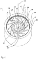
- Figure 1 shows an isolation apparatus 1 in perspective view.
- the isolation apparatus 1 comprises an outer ring 5 with an inner ring through opening 51.
- a guiding device 3 is arranged inside the through opening 51 and further in a direction of isolation DI of the isolation apparatus 1 as shown in Figure10 which can be positioned into the isolation apparatus 1.
- the guiding device 3 is a flat sheet having an annual shape.
- a guiding device through opening 31 is arranged inside the guiding device 3.
- the guiding device through opening 31 can be arranged in the middle of the guiding device 1 in a main plane of the sheet.
- the guiding device 3 can be arranged centrally inside isolation apparatus 1.
- the guiding device 3 comprises a plurality of guiding track ways 32.
- the guiding track ways 32 have the form of an elongated slit. As shown, the guiding track ways 32 can be straight.
- a fictitious extension of the guiding track ways 32 does not run into the guiding device through opening 31.
- the guiding track ways 32 do not run into the guiding track through opening 31.
- the guiding track ways 32 are separated from each other.
- a plurality of segments 2 is arranged.
- the segments 2 are arranged around a segment center 20 which is depicted as a dash and dot line.
- the segment center 20 also forms a fictitious central axis for the embodiment of the isolation apparatus 1 as shown in Figure 1 .
- the segments 2 each comprise a guiding area 22 which is arranged inside an associated guiding track away 32.
- the guiding area 22 is an elongated protrusion.
- the guiding area 22 can comprise two or more separated protrusions in a distance to each other and arranged along a fictitious line.
- the segments 2 each comprise a wedge-shaped segment section 25.
- the wedge-shaped segment sections 25 are arranged in a circle around a segment center 26 in the middle of the segments 2.
- the segment center 26 is represented by a fictitious point in Figure 1 .
- the wedge-shaped segment sections 25 are arranged such that one of their respective sides of the wedge touches the other side of the wedge-shaped segment section 25 of each adjacent segment 2. In this way, the wedge-shaped segment sections 25 form a ring.
- the regions of the sides of the wedge-shaped segment sections 25 inside of this ring each form a gripping area 21 of the segment 2, which are dedicated to be in contact with a substrate 100, when the substrate 100 is gripped by the isolation apparatus 1.
- the above-mentioned ring surrounds an insertion section 11 into which a substrate 100 can be inserted during an electrochemical treatment.
- the shown isolation apparatus 1 allows to arrange a substrate 100 through the insertion section 11 in its inside.
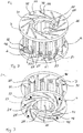
- Figure 2 shows the same embodiment of an isolation apparatus 1 as figure 1 , but in a more oblique angle and without the outer ring. Only the differences and features which are visible additionally to figure 1 are described in the following.
- the adjustment device 4 has the shape of a flat ring. Preferably, it has the same what outer dimensions as the guiding device 3.
- the adjustment device 4 comprises adjustment track ways 42.
- the adjustment track way 42 is curved. A midpoint of the radius of the curvature is located at the side of the adjustment track way 42 at which also the segment center 26 is located.
- an adjustment area 23 of one segment 2 is inserted.
- Each segment 2 comprises a drive plate 24 at which a guiding area 22 and an adjustment area 23 are arranged.
- the drive played 24 is connected to the wedge-shaped segment section 25 and can thus drive it along the guiding track ways 32 and, at the same time, along the adjustment track ways 42.
- the guiding track ways 32 and the adjustment track ways 42 are arranged in an angle to each other. This effects that the segments 2 are forced to move along the guiding track ways 32 when the guiding device 3 and the adjustment device 4 are rotated relative to each other.
- the guiding device 3 and the adjustment device 4 are centered to each other. They stay centered to each other during rotating them relative to each other.
- Figure 3 shows the same embodiment of an isolation apparatus 1 as figure 2 , but in an oblique angle from below. Only the features that are not visible in figure 2 are described in the following.
- the adjustment device 4 comprises an adjustment device through opening 41.
- each adjustment track way 42 one adjustment area 23 of a segment 2 is arranged.
- the adjustment areas 23 each have a circular cross-section such that they are rotatable in their respective adjustment track ways 42.
- Figure 4 shows the same embodiment of an isolation apparatus 1 as figure 2 , but in a state in which the segments are moved further towards the segment center 21 such that the insertion section 11 has a smaller diameter, in comparison.
- the shown state shows the segments 2 at a position in which they are close to the middle of the guiding trackways 32. It is thus possible to further reduce the diameter of the insertion section 11 significantly.
- Figure 5 shows a top view onto the isolation apparatus 1 in a second embodiment into which the substrate 100 is inserted.
- the second embodiment is different from the first embodiment by a different outer ring 5 itn that the outer ring through opening 51 is smaller than in the first embodiment.
- the main diameter of the substrate 100 is gripped by the wedge-shaped segment sections 25 which represents a gripped state of the isolation apparatus.
- the wedge-shaped segment sections 25 are the only part of the segments 2 which is visible in Figure 5 .
- the substrate 100 comprises an isolated section 101 of the substrate 100 which is arranged at an end of the substrate 100 and which shall not be treated electrochemically.
- the isolated section 101 has a smaller diameter than substrate 100.
- the isolated section 101 is concentric to the substrate 100.
- the substrate 100 has a mainly cylindrical shape.
- the segments 2 grip the substrate 100 with a gripping area 21 of each wedge-shaped segment section 25.
- the substrate 100 is gripped at its outer circumference, not at the isolated section 101, which however, would also be possible, in principle.
- Isolated section 101 across the isolation apparatus 1, electrochemically active fluid 1011 in the gaps 102 represents an electrically conductive bridge, whereas the isolation apparatus 1 is electrically non-conducting, at least at relevant surfaces.
- Relevant surfaces can be surfaces which are in contact with the electrochemically active fluid 1011. the electrical resistance as the dependent of the electrical resistance of the fluid in the gaps 102.
- the gaps 102 have a quite small cross-section and extend along the complete height of the wedge-shaped segment sections 25, the resistance is high enough in order to prevent that the isolated section 101 is treated electrochemically.
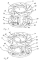
- Figure 6 shows the same embodiment of an isolation apparatus 1 as figure 2 , but with only one segment 2 and in a state in which the segment is moved to the outer end of the guiding track way 32 and the adjustment track way 42.
- the segment 2 does not extend into the guiding device through opening 31 and adjustment device through opening 41 such that the segment 2 also does not extend into the insertion section 11, in this embodiment. This would also be true for the other segments 2 if they would be shown in Figure 6 .
- Figure 7 shows the same embodiment of an isolation apparatus 1 as figure 2 , but with only one segment 2 and in a state in which the segment is moved to the inner end of the guiding track way 32 and the adjustment track way 42.
- the segment 2 does extend into the guiding device through opening 31 and adjustment device through opening 41 to a maximum extent, in this embodiment. This would also be true for the other segments 2 if they were shown in Figure 7 .
- An insertion section 11 with minimum diameter would result.
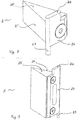
- Figure 8 shows a segment 2 with a height which is lower than the length of the wedge-shaped segment section 25.
- the segment 2 comprises the wedge-shaped segment section 25 and a drive plate 24.
- the drive plate 24 comprises a guiding area 22 and an adjustment area 23 of the segment 2.
- the guiding area 22 and the adjustment area 23 are arranged on opposite ends of the drive plate 24.
- the drive plate 24 is connected to the wedge-shaped segment section 25.
- the bisector of the wedge-shaped segment section 25 is arranged perpendicular to the main plane of the drive plate 24.
- the guiding direction of the guiding area 22 lies in the main plane of the drive plate 24.
- the adjustments area 23 has a cylindrical shape such that the segment 2 can rotate in an adjustment trackway 42.
- Figure 9 shows a segment 2 with a height which is greater than the length of the wedge-shaped segment section 25.
- the other features as shown in Figure 9 are identical with the features of the segment 2 that is shown in Figure 8 .
- FIG 10 shows an electrochemical treatment apparatus 1000.
- the electrochemical treatment apparatus 1000 comprises an electrolyte tank 1010 which is filled with an electrochemical active fluid 1011 up to a fluid level 1012.
- the electrochemical treatment apparatus 1000 comprises a positioning device 1030 and a holding device 1031 for a substrate 100 in order to insert the substrate 100 into the electrolyte tank 1010.
- Below the liquid level 1012 two isolation apparatuses 1 are arranged which is depicted very schematically.
- the isolation apparatuses 1 each have an insertion section 11 in which the substrate 100 can be inserted for treatment.
- each isolation apparatus 1 partitions off an isolation region 1014 from the rest of the electrolyte tank 1010.
- FIG 11 schematically shows the electrochemical treatment apparatus 1000 of Figure 12 .
- the substrate 100 is inserted into the electrolyte tank 1010 and arranged through the insertion sections 11 of the isolation apparatuses 1.
- the isolated sections 101 of the substrate 100 are arranged inside the isolation regions 1014 which are partitions of the electrolytic tank 1010. Electrochemical treatment can happen without treating the isolated sections 101.
- a direction of isolation DI of the isolation apparatus 1 and a transverse direction T which is arranged perpendicular to the direction of isolation DI are drawn as arrows.
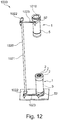
- Figure 12 schematically shows a part of an electrochemical treatment apparatus 1000, wherein significant parts have been omitted for better visibility of two isolation apparatuses 1 and their mechanical linkage 1020.
- the isolation apparatuses 1 are of the same type. Their central axes are aligned to each other. They are also aligned along the direction of isolation DI of the isolation apparatus 1 in case a substrate 100 is inserted into the isolation apparatuses 1.
- Each of the isolation apparatuses 1 comprises an outer ring 5 which can be turned for adjustment of the diameter of the insertion section 11.
- Each of the outer rings comprises a protrusion 52.
- the protrusions 52 are arranged at the same position at the circumference of the outer ring 5 such that they are aligned along the direction of isolation DI of the isolation apparatus 1.
- Each of the food rules and 52 are connected rotatably to adjustment rods 1023.
- the adjustment rods 1023 are also connected rotatably to adjustment levers 1022, respectively, in a way that the movement of the adjustment rods 1023 can effect a rotation of the outer ring 5 of the isolation apparatus 1.
- the adjustment levers 1022 are connected fixedly to an adjustment column 1021 which is rotatable together with the adjustment levers 1022.
- the isolation apparatus 1 can be adjusted by turning the adjustment column 1021. It is also possible that the isolation apparatus 1 is adjustable by a linear actuator which acts on one of the protrusions 52, on an adjustment rod 1023 or on an adjustment lever 1022.
Landscapes
- Chemical & Material Sciences (AREA)
- Engineering & Computer Science (AREA)
- Chemical Kinetics & Catalysis (AREA)
- Electrochemistry (AREA)
- Materials Engineering (AREA)
- Metallurgy (AREA)
- Organic Chemistry (AREA)
- Cleaning Or Drying Semiconductors (AREA)
Abstract
Description
- This invention relates to an adjustable isolation apparatus for an electrochemical treatment apparatus in order to isolate a section of an elongated substrate in a direction of isolation of the isolating apparatus such that a significant electrochemical treatment of the isolated section by an electrochemically active liquid is preventable, wherein the substrate has a direction of isolation along which the section is isolated from another region of the substrate; an electrochemical treatment apparatus comprising the adjustable isolation apparatus and a method to adjust the adjustable isolation apparatus for an electrochemical treatment apparatus.
- In the following, objects to be processed will be referred to as a rod. Plants for electrochemical pickling, galvanizing and/or electrochemical cleaning of elongated objects, particularly round rods, are well known in the art. At one end or both ends, these rods may be tapered and/or threaded. The invention, however, is not limited to the processing of round rods. It is also suited for the treatment of rods having another cross-section, even of arbitrary elongated objects or even the ends of any object.
- Electrochemical processing of rods which act as a piston of a cylinder, especially of a shock absorber cylinder, can help to improve the wear and corrosion resistance properties. To this purpose, the rods can be electrolytically plated, for example with hard-chromium, at such surfaces which are subjected to wear during operation. Other places of the rods preferably remain uncoated or are at least partially provided with a thin layer of chrome for temporary protection of their surface. In order to improve the adherence of the chromium layer, the surface can be electrochemically pickled first. Insoluble electrodes are preferably employed for an electrochemical process. Between the various steps of the treatment, the rods can be cleaned in galvanizing lines. A conveying facility brings the rods from one processing station to the other.
- In the state of the art,
DE 197 22 987 A1 discloses a method and a device for partial electrochemical treatment of bar-shaped substrates. In order to prevent the treatment of a section of the substrates, it is proposed to use masks that increase the electrical resistance along a path of a fluid from an electrode to the section which is not to be treated. In this way, treatment of these sections is prevented. Such masks can be provided with a collar that forms a through hole through the mask and can, in operation, surround the substrate which extends through the through hole. As an improvement of this system,US 6,508,926 proposes to center the substrate inside the mask which can be damaged by decentering. - However, there is a significant shortcoming of the state of the art. The treatment of objects of different diameter requires exchanging the mask and adjusting it according to the properties of the new objects, by hand. This requires time and manpower, and also endangers workers by noxious chemical substances.
- It is an object of the invention to provide an adjustable isolation apparatus, an electrochemical treatment apparatus comprising the adjustable isolation apparatus and a method to adjust the adjustable isolation apparatus for an electrochemical treatment apparatus according to the independent claims. The dependent claims concern preferred embodiments of the invention.
- An adjustable isolation apparatus for an electrochemical treatment apparatus is proposed, wherein the isolation apparatus is configured to isolate a section of an elongated substrate. Therefore the apparatus is capable to receive and hold an elongated substrate for electrochemical treatment. Thus, electrochemical treatment of the isolated section by an electrochemically active liquid is prevented. The substrate has a direction of isolation along which the section is isolated from another region of the substrate. This is the direction of isolation along which the isolation apparatus is effective. The direction of isolation can also be a longitudinal direction of the substrate.
- The isolation apparatus comprises a plurality of segments. The segments can be arranged around a segment center which defines the segment center. The segments center means a fictitious midpoint in the middle of sections of the segments which are configured to approximate or grip group the substrate. The segment center is located outside of the segments themselves. It is usually located in a substrate which is inserted into the isolation apparatus. In operation, the segments surround the substrate at least approximately in transverse direction to the direction of isolation. The segments are movable towards or away from the substrate by adjustment of the isolation apparatus. In an adjusted state of the segments, an electrical resistance in an electrochemically active fluid is effected in direction of isolation of the substrate across the isolation apparatus which is such high that the isolated section of the substrate is not significantly treated electrochemically, especially not significantly electroplated with a metal (that means not electroplated in a way which leads to functional deposits or functional surfaces of the substrate to be treated). This is achieved by reducing a cross-section of gaps between the segments and between the segments and the substrate in which the liquid is present.
- An adjusted state of the isolation apparatus is a state in which the isolation apparatus is adjusted such that the segments at least almost touch the substrate or grip it. In the adjusted state, the electrical resistance is significantly increased in comparison to a not adjusted state in which the segments have a significant distance from substrate. A significant electrochemical treatment means that a coating is achieved that fulfills the intended purpose at a location of the substrate. The purpose of the isolation apparatus is to prevent significant electrochemical treatment of the isolated section of the substrate. Preferably, the isolated section is not electrochemically treated.
- The electrochemical treatment is preferably plating, particularly by chromium plating. However, other electrochemical processes can be employed, for example for cleaning, stripping, polishing or other processes, especially, but not exclusively, for the preparation of a plating process, or an electrochemical intermediate or finishing process.
- The isolation apparatus can be used in a state in which it is submerged in the electrochemically active fluid. However, it is also possible to use it partially submerged or as a sealing device in order to seal the isolated section from being submerged in the fluid.
- In a preferred embodiment the isolation apparatus comprises a guiding device which comprises a plurality of guiding track ways along which the segments are movable towards or away from the substrate, wherein, preferably, the isolation apparatus comprises one guiding track way for each segment, and/or wherein, preferably, each of the guiding track ways has the same form, and/or wherein, preferably, the guiding track ways are straight, and/or wherein, preferably, the guiding device comprises a guiding device through opening which is configured in the isolation apparatus such that through the through opening, the substrate is arrangeable and/or wherein, preferably, a fictitious straight extension of the guiding track way does not run through the segment center or through the guiding device through opening.
- The isolation apparatus can comprise a guiding device which comprises a plurality of guiding track ways along which the segments are movable towards or away from the substrate. This particularly happens when adjusting the isolation apparatus. For each segment, the isolation apparatus can comprise one dedicated guiding track way. Then, the segments are movable relative to each other by effect of the guiding track ways. It is, alternatively, also possible to guide a segment along each other one. The guiding track ways can be arranged in a guiding plane of the guiding device.
- Preferably, the guiding track ways each have the same form. This enables to uniformly move the segments symmetrically in relation to a center which is preferably located in the substrate, preferably in the middle of its cross section.
- The guiding track ways can be straight. Preferably, a fictitious straight extension of the guiding track way does not run through the segment center. This is especially helpful in an isolation apparatus which has segments that touch each other and which do not move directly towards the segment center. Such segments can move towards the substrate with a tangential component of the movement relative to the substrate. By such a movement, a segment passes the segment center at its side. Then, the segments can come closer to the segment center if sections of the segments are located sidewards of guiding track ways and in direction to the segment center. This can additionally be supported by the shape of the segment. Its border can move towards the segment center during the movement sidewards in relation to the segment center such that the distance to the segment center or the substrate, respectively, decreases. This can be achieved by a wedge shape of a section of the segment, for example.
- In a preferred embodiment, the segments have a wedge-shaped segment section, wherein, preferably, a side area of each wedge-shaped segment section that is the most oriented towards the segment center has the same angle relative to a fictitious line that emanates from the segment center.
- Preferably, the segments have a wedge-shaped segment section which has the purpose of isolating the isolated section of the substrate by approaching the substrate or gripping it. Particularly, the wedge-shaped segment section is located at a side of a guiding for the segment that is oriented towards the segment center. Preferably, a side area of each wedge-shaped segment section that is oriented towards the segment center of the sides of the wedge-shaped segment sections the most, has the same angle relative to a fictitious line that emanates from the segment center. Then, a symmetrical adjustment movement can be carried out by the segments. All segments can have same form, at least at the wedge-shaped segment section. Preferably, the wedge-shaped segment section has a fictitious bisecting line that is oriented perpendicular to the direction of the guiding track way. The wedge angle is preferably 360° divided by the number of segments, at least approximately. The side surfaces of the wedge are preferably even. The wedge-shaped segment sections can touch each other with their even surfaces which can lead to a sealing effect between them. Touching segments can reduce or close a cross section of a direct path for electrochemical active fluid across the isolation apparatus and towards the isolated section of the substrate. The touching area between adjacent segments can act as a sealing which is adjustable regarding its inner diameter.
- Preferably, in a gripped state of the isolation apparatus, the substrate is approached or gripped by at least three of the segments. Preferably, the substrate is gripped by all segments, wherein preferably, the substrate is gripped by the same side of wedge-shaped segment sections of at least three segments.
- Preferably, the guiding device comprises an insertion section into which the substrate can be arranged for treatment. The insertion section can have the form of a recess or an opening which is configured in the isolation apparatus such that the substrate can be arranged in the recess or through the through opening. During adjustment, surface segments can be moved inside the recess or through opening. The guiding track ways can for example be oriented such that they do not extend into the insertion section. This enhances the rigidity of the guiding device, especially in case that the insertion section is a through opening.
- The guiding device can have an even surface as a guiding plane in which the guiding track ways can be arranged, preferably as a groove or a slit or a ridge along which the segments can be guided. Those segments can also be guided along the guiding plane. The guiding device can have the form of a ring or comprise a ring.
- In a preferred embodiment, the isolation apparatus comprises an adjustment device which is configured to move at least one segment along the guiding track way, wherein, preferably, the adjustment device comprises at least one adjustment track way, wherein the adjustment device is movable relative to the guiding device. in order to adjust the isolation apparatus, wherein at least a subset of the segments is guidable along the adjustment track ways by the adjustment, and/or wherein, preferably, the adjustment device is rotatable relative to the guiding device in order to adjust the isolation apparatus, wherein, preferably, the maximum adjustment rotation is 1/3 of a revolution or less, preferably between 80° and 100°, and/or wherein, preferably, the adjustment device comprises adjustment track ways for the segment, and/or wherein, preferably, the adjustment track way has a course which is different from the course of the guiding track way of the same segment as seen in a projection of the adjustment track ways in the direction of isolation into a plane of the guiding track ways, and/or wherein the adjustment track ways of each segment have the same form, and/or wherein the adjustment device preferably comprises an adjustment device through opening through that the substrate is arrangeable in an isolated state of an end of the substrate, wherein, preferably, a fictitious extension of the adjustment track way does not run through the segment center or through the adjustment device through opening.
- Preferably, the segments are fixed in regard of rotation relative to one of the guiding device and the adjustment device, preferably the guiding device. The other one of the guiding device and the adjustment device can be rotatable relative to each of the segments.
- The isolation apparatus preferably comprises an adjustment device which is configured to move the segments along the guiding track way towards or away from the substrate. The adjustment device can comprise adjustment track ways for the segments. The adjustment track ways can be arranged in an adjustment plane of the adjustment device. The segments can be arranged between the adjustment plane and the guiding plane. At least a subset of the segments can be guided along the adjustment track ways. Preferably, the adjustment device comprises an adjustment track way for each segment.
- In a preferred embodiment, the adjustment track way is oriented in another direction as the guiding track way as seen in a projection into a plane of the track ways along the direction of isolation, wherein, preferably the adjustment track way is oriented in an angle of more than 20° in regard of the guiding track way, preferably at each point of the adjustment track way, or is not straight, preferably curved and more preferably curved such that a concave side of the curvature is more oriented towards the segment center than a convex side of the curvature.
- The adjustment track way can have a course which is different from the course of the guiding track way of the same segment as seen in a projection of the adjustment track ways in the direction of isolation into an area of the guiding track ways. Then, a relative movement between the adjustment device and the guiding device, especially between the adjustment track way and the guiding track way, can force the segments to move along the guiding track ways and along the adjustment track ways. Preferably, the adjustment track ways are oriented in another direction as the track ways for the same segment, as seen in a projection into a plane of the track ways along the direction of isolation. The adjustment track ways can for example be oriented in an adjustment angle that is defined relative to the corresponding guide track ways of more than 20°, preferably at each point of the adjustment track way. By the adjustment angle, the smaller one of the supplementary angles is meant. The adjustment track way can be not straight, is preferably curved and more preferably curved such that a concave side of the curvature is more oriented towards the segment center than a convex side of the curvature. By curved adjustment track ways, the required turning angle of the adjustment device relative to the guiding device can be adapted. Also, the curvature can compensate for non-linearity between the movements of the segments towards the substrate and the turning angle of the adjustment device.
- In a preferred embodiment, the segments are movable simultaneously during adjustment, and are preferably movable symmetrically in regard of the center of the segments. The adjustment track ways for each segment can have the same form. The adjustment track ways can for example be a groove or a slit or a ridge along which the segments can be adjusted.
- Preferably, the adjustment device is movable relative to the guiding device in order to adjust the isolation apparatus. By the movement, the segment can, for example, slide along adjustment track way. Preferably, the adjustment device can be rotated relative to the guiding device in order to adjust the isolation apparatus. It is also possible to effect the adjustment movement by a translational relative movement between one or more segments and the adjustment device. A rotation, however, has the advantage that it requires less space for its movement, as the adjustment device does not have to be moved to another place. Preferably, the maximum adjustment rotation is 1/3 of a revolution or less, preferably between 80° and 100°. This solution has the advantage that the movement can be effected by an adjustment rod which can be pushed or pulled for adjustment. Thus, the adjustment can be effected by a linear actuator easily. Furthermore, in case that a basin is just as wide as the isolation apparatus or few more and when using a projecting section of the adjustment device for driving the adjustment device, this projecting section can still be moved between the inner walls of the basin with this amount of rotation. It is preferred that the adjustment device comprises a recess or a through opening in which or through which the substrate can be arranged for treatment.
- Preferably, the adjustment device and/or the guiding device have an outer case that has a mainly cylindrical form at its outer circumference. For example, the outer case can have tube-like or annular basic form. The outer case can have a projecting section at its outer circumference which is configured to be connected to a drive device for rotating the outer case. The outer case can be connected to one of the guiding device and the adjustment device in order to rotate it. In this way, the relative movement between the drive device and the adjustment device can be effected. A substrate can be gripped and released by action of the drive device.
- Preferably, the segments have a wedge-shaped segment section. Each side of the wedge-shaped segment sections that is oriented towards the segment center the most can have the same angle relative to a fictitious line that emanates from the segment center. Preferably, each of wedge-shaped segment section has the same distance to the center of the segments. In this way, a symmetrical arrangement and preferably also a symmetrical movement of the wedge shaped segment sections can be achieved. The wedge-shaped segment sections can be moved through the insertion section. Preferably, the sloped sides of adjacent wedge-shaped segment sections touch each other. During adjustment, these sides can slide along each other in a relative movement. This enables a sealing effect though the position of the segments changes.
- Preferably, each segment comprises a gripping area, a guiding area and an adjustment area. In a gripped or almost gripped state, the gripping area can be oriented parallel to an outer surface of the substrate which it touches or almost touches. Preferably, the gripping the area is part of a wedge-shaped segment section of the segment. The guiding area of the segment can be a surface area of the segment which is configured to slide along a guiding of the guiding device. Preferably, the guiding area has the form of an elongated protrusion. An adjustment area of a segment is preferably rotatable relative to an adjustment device and can be connected to it by form-locking. It can protrude from a segment and have a cylindrical form.
- In a preferred embodiment, in a gripped state of the isolation apparatus, the substrate is gripped by at least three of the segments, preferably by all segments, preferably by twelve segments, wherein preferably, the substrate is gripped by a respective side of wedge-shaped segment sections of at least three segments.
- The sealing effect of the segments to the form of the substrate and thus the isolation of the section of the substrate is generally dependent on the number of segments. This is particularly true for substrates having a circular cross-section and different diameters. When using segments with wedge-shaped segment sections for gripping or approach to the substrate, for example at least eight segments can be used, preferably twelve segments. It is conceivable that a section of a segment that touches the substrate can be made of an elastic material or be an elastic layer on the surface of the segment. In this way, the adaptation to the form of the substrate can be improved.
- In a preferred embedment, a height of adjacent segments at a location of contact of the segments is at least 2 mm and preferably approximately 10 mm.
- The height of the segments is preferably at least 2 mm, more preferred between 5 and 15 mm, most preferred between 9 and 11 mm, the letter being in preferably combination with between 10 and 14 segments. Preferably, at least the surface that approaches or groups the substrate is straight in direction of isolation DI of the isolation apparatus. Then, for example a cylindrical substrate can be approached or gripped by a greater area of the segments, and isolation is improved.
- It is conceivable that the segments and the guide device are made of one piece. Then, the height of the segments and a part of the guiding device which comprises that the guiding can for example be between 2 and 3 mm.
- In a preferred embodiment, at least at one surface of a gripping segment and/or the guiding device and/or the adjustment device comprises a material that is resistant against liquid chemical agents of an electrochemical treatment, preferably titanium, corrosion resistant steel or alloy, a material with corrosion resistant coating, rubber or a plastic material, preferably PVDF.
- The guiding device and the adjustment device can have the form of a disc, respectively. The isolation apparatus, especially the guiding device and the adjustment device and/or the segments can be made of titanium, corrosion resistant steel or alloy, a material with a corrosion resistant coating or a plastic material, preferably PVDF. Preferably, at least at a part of the surface of the isolation apparatus is electrically non-conducting, preferably a part which is in contact with the electrochemically active fluid and/or the substrate. The titanium can be electrically isolating by a layer of a titanium compound material such as titanium oxide or another coating. Preferably, the isolation apparatus is configured to be used at least partially immersed in a chemically and/or electrochemically active liquid.
- In a further aspect of the invention, an electrochemical treatment apparatus it is proposed, which comprises an adjustable isolation apparatus as described above.
- In a preferred embodiment, the electrochemical treatment apparatus comprises an electrolyte tank or basin in which the section of the elongated substrate which is not to be treated is arranged in a region which is accessible for electrochemically active fluid only via one or more isolation apparatuses.
- In a preferred embodiment, the electrochemical treatment apparatus comprises a hydraulic, a pneumatic and/or an electric adjustment drive in order to move the guiding device and the adjustment device relative to each other, wherein preferably, at least two isolation apparatuses are drivable by one adjustment drive, wherein, preferably, the isolation apparatuses are mechanically connected for simultaneous adjustment, wherein, preferably, the adjustment drives are connected, preferably by a mechanical linkage device.
- Preferably, the isolation apparatus comprises a hydraulic, a pneumatic and/or an electric adjustment drive in order to move the guiding device and the adjustment device relative to each other. For example, the drive can be the linear drive and be connected to a protrusion, which is part of the adjustment device or of the guiding device. Preferably, least two isolation apparatuses can be driven by one common adjustment drive, wherein, for this purpose, the isolation apparatuses can be mechanically linked for simultaneous adjustment. The adjustment drives can be connected by a mechanical linkage device. In a further aspect of the invention, a method to adjust an adjustable isolation apparatus for an electrochemical treatment apparatus is proposed, in order to isolate a section of an elongated substrate by the isolation apparatus such that a significant electrochemical treatment of the isolated section by an electrochemically active liquid is prevented, wherein the substrate has a direction of isolation along which the section is isolated from another region of the substrate, wherein the isolation apparatus comprises a plurality of segments which are arranged at least approximately in a transverse direction to the direction of isolation, wherein, by adjustment of the segments, a cross-section of gaps that bypass the segments in direction of isolation between the segments themselves and/or between one or more segments and the substrate is reduced such that the isolated section of the substrate is not significantly treated.
- The purpose of the proposed method is to isolate a section of an elongated substrate by the isolation apparatus, such that a significant electrochemical treatment of the isolated section by an electrochemically active liquid is preventable. An isolation apparatus as described above can be used in an electrochemical treatment apparatus. The isolation apparatus comprises a plurality of segments which are arranged at least approximately in a transverse direction to the direction of isolation, wherein the segments can be moved towards or away from the substrate by adjustment of the isolation apparatus. The segments, in an adjusted state of the segments, effect an electrical resistance in an electrochemically active fluid across the isolation apparatus such that the isolated section of the substrate is not treated electrochemically. The cross-section of gaps between the segments and between the segments and the substrate in which the liquid is present can be reduced by but adjustment of the isolation apparatus. Preferably, at least a part of the isolation apparatus can be rotated for adjustment.
- In a preferred embodiment, a part of the isolation apparatus is rotated for adjustment, wherein the segments are moved along a guiding track way towards or away from the substrate and, preferably, along an adjustment track way, wherein the guiding track way and the adjustment track way are moved relative to each other by the rotation.
- The attached figures show, as an example only, an embodiment of the invention.
-
Figure 1 shows a schematical perspective view of an embodiment of an isolation apparatus, -
Figure 2 shows a schematical perspective view oblique from above of segments, the guiding device and an adjustment device of the isolation apparatus ofFigure 1 in an almost maximally opened position, -
Figure 3 shows a schematical perspective view oblique from below of segments, the guiding device and an adjustment device of the isolation apparatus ofFigure 1 , -
Figure 4 shows a schematical perspective view ofFigure 2 , but with one segment only which is in a fluid opened position, -
Figure 5 shows a top view on the isolation apparatus with a gripped substrate, -
Figure 6 shows the schematical perspective view ofFigure 2 , but with one segment only which is in maximum opened position, -
Figure 7 shows the schematical perspective view ofFigure 6 , wherein the segment is in maximally closed position, -
Figure 8 shows a schematical perspective view of a single segment with a low height, -
Figure 9 shows a schematical perspective view of a single segment with an increased height, -
Figure 10 shows a schematical cross-section through an electrochemical treatment apparatus, wherein a substrate is outside of the treatment apparatus, -
Figure 11 shows the schematical cross-section ofFigure 10 , wherein a substrate is inside of the treatment of the treatment apparatus, -
Figure 12 shows a schematical perspective view on part of the treatment apparatus that comprises two isolation apparatuses and a mechanical linkage between the isolation apparatuses. -
Figure 1 shows anisolation apparatus 1 in perspective view. Theisolation apparatus 1 comprises anouter ring 5 with an inner ring throughopening 51. - Inside the through
opening 51 and further in a direction of isolation DI of theisolation apparatus 1 as shown inFigure10 which can be positioned into theisolation apparatus 1, a guidingdevice 3 is arranged. The guidingdevice 3 is a flat sheet having an annual shape. A guiding device throughopening 31 is arranged inside the guidingdevice 3. As shown, the guiding device through opening 31 can be arranged in the middle of the guidingdevice 1 in a main plane of the sheet. The guidingdevice 3 can be arranged centrally insideisolation apparatus 1. The guidingdevice 3 comprises a plurality of guidingtrack ways 32. The guidingtrack ways 32 have the form of an elongated slit. As shown, the guidingtrack ways 32 can be straight. A fictitious extension of the guidingtrack ways 32 does not run into the guiding device throughopening 31. The guidingtrack ways 32 do not run into the guiding track throughopening 31. The guidingtrack ways 32 are separated from each other. - Beyond the guiding
device 3, a plurality ofsegments 2 is arranged. Thesegments 2 are arranged around asegment center 20 which is depicted as a dash and dot line. Thesegment center 20 also forms a fictitious central axis for the embodiment of theisolation apparatus 1 as shown inFigure 1 . Thesegments 2 each comprise a guidingarea 22 which is arranged inside an associated guiding track away 32. The guidingarea 22 is an elongated protrusion. Alternatively, the guidingarea 22 can comprise two or more separated protrusions in a distance to each other and arranged along a fictitious line. Thesegments 2 each comprise a wedge-shapedsegment section 25. The wedge-shapedsegment sections 25 are arranged in a circle around asegment center 26 in the middle of thesegments 2. Thesegment center 26 is represented by a fictitious point inFigure 1 . The wedge-shapedsegment sections 25 are arranged such that one of their respective sides of the wedge touches the other side of the wedge-shapedsegment section 25 of eachadjacent segment 2. In this way, the wedge-shapedsegment sections 25 form a ring. The regions of the sides of the wedge-shapedsegment sections 25 inside of this ring each form a grippingarea 21 of thesegment 2, which are dedicated to be in contact with asubstrate 100, when thesubstrate 100 is gripped by theisolation apparatus 1. The above-mentioned ring surrounds aninsertion section 11 into which asubstrate 100 can be inserted during an electrochemical treatment. The shownisolation apparatus 1 allows to arrange asubstrate 100 through theinsertion section 11 in its inside. -
Figure 2 shows the same embodiment of anisolation apparatus 1 asfigure 1 , but in a more oblique angle and without the outer ring. Only the differences and features which are visible additionally tofigure 1 are described in the following. - In
Figure 2 , additionally anadjustment device 4 is visible. Theadjustment device 4 has the shape of a flat ring. Preferably, it has the same what outer dimensions as the guidingdevice 3. Theadjustment device 4 comprisesadjustment track ways 42. Theadjustment track way 42 is curved. A midpoint of the radius of the curvature is located at the side of theadjustment track way 42 at which also thesegment center 26 is located. In eachadjustment track way 42, anadjustment area 23 of onesegment 2 is inserted. Eachsegment 2 comprises adrive plate 24 at which a guidingarea 22 and anadjustment area 23 are arranged. The drive played 24 is connected to the wedge-shapedsegment section 25 and can thus drive it along the guidingtrack ways 32 and, at the same time, along theadjustment track ways 42. In a projection of the guidingdevice 3 into a plane of theadjustment track ways 42, the guidingtrack ways 32 and theadjustment track ways 42 are arranged in an angle to each other. This effects that thesegments 2 are forced to move along the guidingtrack ways 32 when the guidingdevice 3 and theadjustment device 4 are rotated relative to each other. The guidingdevice 3 and theadjustment device 4 are centered to each other. They stay centered to each other during rotating them relative to each other. - In
Figure 2 , as well as inFigure 1 and also inFigure 3 , theinsertion section 11 is opened almost at its maximum. This can be recognized by the position of the guidingareas 22 of thesegments 2 in their respectiveguiding track way 32 which is almost at the outer end. The guidingareas 22 of the segments guarantee that thesegments 2 cannot rotate relative to theguiding device 3. -
Figure 3 shows the same embodiment of anisolation apparatus 1 asfigure 2 , but in an oblique angle from below. Only the features that are not visible infigure 2 are described in the following. - The
adjustment device 4 comprises an adjustment device throughopening 41. In eachadjustment track way 42, oneadjustment area 23 of asegment 2 is arranged. Theadjustment areas 23 each have a circular cross-section such that they are rotatable in their respectiveadjustment track ways 42. -
Figure 4 shows the same embodiment of anisolation apparatus 1 asfigure 2 , but in a state in which the segments are moved further towards thesegment center 21 such that theinsertion section 11 has a smaller diameter, in comparison. The shown state shows thesegments 2 at a position in which they are close to the middle of the guidingtrackways 32. It is thus possible to further reduce the diameter of theinsertion section 11 significantly. -
Figure 5 shows a top view onto theisolation apparatus 1 in a second embodiment into which thesubstrate 100 is inserted. The second embodiment is different from the first embodiment by a differentouter ring 5 itn that the outer ring throughopening 51 is smaller than in the first embodiment. The main diameter of thesubstrate 100 is gripped by the wedge-shapedsegment sections 25 which represents a gripped state of the isolation apparatus. The wedge-shapedsegment sections 25 are the only part of thesegments 2 which is visible inFigure 5 . Thesubstrate 100 comprises anisolated section 101 of thesubstrate 100 which is arranged at an end of thesubstrate 100 and which shall not be treated electrochemically. Theisolated section 101 has a smaller diameter thansubstrate 100. Theisolated section 101 is concentric to thesubstrate 100. Thesubstrate 100 has a mainly cylindrical shape. - The
segments 2 grip thesubstrate 100 with a grippingarea 21 of each wedge-shapedsegment section 25. Thesubstrate 100 is gripped at its outer circumference, not at theisolated section 101, which however, would also be possible, in principle. At the tip of each wedge-shapedsegment section 25, there is agap 102 between the neighbour wedge-shapedsegment section 25.Isolated section 101 across theisolation apparatus 1, electrochemically active fluid 1011 in thegaps 102 represents an electrically conductive bridge, whereas theisolation apparatus 1 is electrically non-conducting, at least at relevant surfaces. Relevant surfaces can be surfaces which are in contact with the electrochemicallyactive fluid 1011. the electrical resistance as the dependent of the electrical resistance of the fluid in thegaps 102. As thegaps 102 have a quite small cross-section and extend along the complete height of the wedge-shapedsegment sections 25, the resistance is high enough in order to prevent that theisolated section 101 is treated electrochemically. -
Figure 6 shows the same embodiment of anisolation apparatus 1 asfigure 2 , but with only onesegment 2 and in a state in which the segment is moved to the outer end of the guidingtrack way 32 and theadjustment track way 42. Thesegment 2 does not extend into the guiding device throughopening 31 and adjustment device through opening 41 such that thesegment 2 also does not extend into theinsertion section 11, in this embodiment. This would also be true for theother segments 2 if they would be shown inFigure 6 . -
Figure 7 shows the same embodiment of anisolation apparatus 1 asfigure 2 , but with only onesegment 2 and in a state in which the segment is moved to the inner end of the guidingtrack way 32 and theadjustment track way 42. Thesegment 2 does extend into the guiding device throughopening 31 and adjustment device through opening 41 to a maximum extent, in this embodiment. This would also be true for theother segments 2 if they were shown inFigure 7 . Aninsertion section 11 with minimum diameter would result. -
Figure 8 shows asegment 2 with a height which is lower than the length of the wedge-shapedsegment section 25. Thesegment 2 comprises the wedge-shapedsegment section 25 and adrive plate 24. Thedrive plate 24 comprises a guidingarea 22 and anadjustment area 23 of thesegment 2. The guidingarea 22 and theadjustment area 23 are arranged on opposite ends of thedrive plate 24. Thedrive plate 24 is connected to the wedge-shapedsegment section 25. The bisector of the wedge-shapedsegment section 25 is arranged perpendicular to the main plane of thedrive plate 24. The guiding direction of the guidingarea 22 lies in the main plane of thedrive plate 24. Theadjustments area 23 has a cylindrical shape such that thesegment 2 can rotate in anadjustment trackway 42. -
Figure 9 shows asegment 2 with a height which is greater than the length of the wedge-shapedsegment section 25. The other features as shown inFigure 9 are identical with the features of thesegment 2 that is shown inFigure 8 . -
Figure 10 shows anelectrochemical treatment apparatus 1000. Theelectrochemical treatment apparatus 1000 comprises anelectrolyte tank 1010 which is filled with an electrochemical active fluid 1011 up to afluid level 1012. Theelectrochemical treatment apparatus 1000 comprises apositioning device 1030 and aholding device 1031 for asubstrate 100 in order to insert thesubstrate 100 into theelectrolyte tank 1010. Below theliquid level 1012, twoisolation apparatuses 1 are arranged which is depicted very schematically. Theisolation apparatuses 1 each have aninsertion section 11 in which thesubstrate 100 can be inserted for treatment. Towards the end of thesubstrate 100, eachisolation apparatus 1 partitions off anisolation region 1014 from the rest of theelectrolyte tank 1010. -
Figure 11 schematically shows theelectrochemical treatment apparatus 1000 ofFigure 12 . In difference toFigure 12 , thesubstrate 100 is inserted into theelectrolyte tank 1010 and arranged through theinsertion sections 11 of theisolation apparatuses 1. Theisolated sections 101 of thesubstrate 100 are arranged inside theisolation regions 1014 which are partitions of theelectrolytic tank 1010. Electrochemical treatment can happen without treating theisolated sections 101. - In
Figure 11 , a direction of isolation DI of theisolation apparatus 1 and a transverse direction T which is arranged perpendicular to the direction of isolation DI are drawn as arrows. -
Figure 12 schematically shows a part of anelectrochemical treatment apparatus 1000, wherein significant parts have been omitted for better visibility of twoisolation apparatuses 1 and theirmechanical linkage 1020. - The
isolation apparatuses 1 are of the same type. Their central axes are aligned to each other. They are also aligned along the direction of isolation DI of theisolation apparatus 1 in case asubstrate 100 is inserted into theisolation apparatuses 1. Each of theisolation apparatuses 1 comprises anouter ring 5 which can be turned for adjustment of the diameter of theinsertion section 11. Each of the outer rings comprises aprotrusion 52. Theprotrusions 52 are arranged at the same position at the circumference of theouter ring 5 such that they are aligned along the direction of isolation DI of theisolation apparatus 1. Each of the food rules and 52 are connected rotatably toadjustment rods 1023. Theadjustment rods 1023 are also connected rotatably toadjustment levers 1022, respectively, in a way that the movement of theadjustment rods 1023 can effect a rotation of theouter ring 5 of theisolation apparatus 1. The adjustment levers 1022 are connected fixedly to anadjustment column 1021 which is rotatable together with the adjustment levers 1022. Theisolation apparatus 1 can be adjusted by turning theadjustment column 1021. It is also possible that theisolation apparatus 1 is adjustable by a linear actuator which acts on one of theprotrusions 52, on anadjustment rod 1023 or on anadjustment lever 1022. -
- 1 Isolation apparatus
- 11 Insertion section
- 2 Segment
- 20 Segment center
- 21 Gripping area of a segment
- 22 Guiding area of a segment
- 23 Adjustment area of a segment
- 24 Drive plate
- 25 Wedge-shaped segment section
- 26 Segment center
- 3 Guiding device
- 31 Guiding device through opening
- 32 guiding track way of guiding device
- 4 Adjustment device
- 41 Adjustment device through opening
- 42 Adjustment track way
- 5 Outer ring
- 51 Outer ring through opening
- 52 Protrusion
- 100 Substrate
- 101 Isolated section of the elongated substrate, preferably an end portion of a substrate
- 102 Gap between segment and substrate
- 1000 Electrochemical treatment apparatus
- 1010 Electrolyte tank
- 1011 Electrochemically active media
- 1012 Level of the fluid
- 1014 Isolation region
- 1020 Mechanical linkage
- 1021 Adjustment column
- 1022 Adjustment lever
- 1023 Adjustment rod
- 1030 Positioning device
- 1031 Holding device
- DI Direction of isolation of the isolating apparatus
- T Transverse direction to the direction of isolation DI of the
isolation apparatus 1
Claims (14)
- Adjustable isolation apparatus (1) for an electrochemical treatment apparatus (1000) in order to isolate a section (101) of an elongated substrate (100) in a direction of isolation (DI) of the isolating apparatus (1) such that a significant electrochemical treatment of the isolated section (101) by an electrochemically active liquid is preventable, wherein the substrate (100) has a direction of isolation (DI) along which the section (101) is isolated from another region of the substrate (100),
characterized in that the isolation apparatus (1) comprises a plurality of segments (2) which are arranged around a segment center (20) and, in operation, surround the substrate (100) at least approximately in transverse direction (T) to the direction of isolation (DI), wherein the segments (2) are movable towards or away from the substrate (100) by adjustment of the isolation apparatus (1),
wherein by adjustment of the segments (2), a cross-section of gaps (102), that bypass the segments (2) in direction of isolation (DI) between the segments (2) themselves and/or between one or more segments (2) and the substrate (100), is reducible such that the isolated section (101) of the substrate (100) is not significantly treated. - Isolation apparatus (1) according to claim 1, characterized in that the isolation apparatus (1) comprises a guiding device (3) which comprises a plurality of guiding track ways (32) along which the segments (2) are movable towards or away from the substrate (100),
wherein, preferably, the isolation apparatus (1) comprises one guiding track way (32) for each segment (2), and/or
wherein, preferably, each of the guiding track ways (32) has the same form, and/or
wherein, preferably, the guiding track ways (32) are straight, and/or
wherein, preferably, the guiding device (3) comprises a guiding device through opening (31) which is configured in the isolation apparatus (1) such that through the through opening, the substrate (100) is arrangeable and/or
wherein, preferably, a fictitious straight extension of the guiding track way (32) does not run through the segment center (20) or through the guiding device through opening (31). - Isolation apparatus (1) according to claim 1 or 2, characterized in that the isolation apparatus (1) comprises an adjustment device (4) which is configured to move at least one segment (2) along the guiding track way (32),
wherein, preferably, the adjustment device (4) comprises at least one adjustment track way (42), wherein the adjustment device (4) is movable relative to the guiding device (3) in order to adjust the isolation apparatus (1), wherein at least a subset of the segments (2) is guidable along the adjustment track ways (42) by the adjustment, and/or
wherein, preferably, the adjustment device (4) is rotatable relative to the guiding device (5) in order to adjust the isolation apparatus (1), wherein, preferably, the maximum adjustment rotation is 1/3 of a revolution or less, preferably between 80° and 100°, and/or
wherein, preferably, the adjustment device (4) comprises adjustment track ways (42) for the segments (2), and/or
wherein, preferably, the adjustment track way (42) has a course which is different from the course of the guiding track way (32) of the same segment (2) as seen in a projection of the adjustment track ways (42) in the direction of isolation (DI) into a plane of the guiding track ways (32), and/or wherein the adjustment track ways (42) of each segment (2) have the same form, and/or
wherein the adjustment device (4) preferably comprises an adjustment device through opening (41) through that the substrate (100) is arrangeable in an isolated state of an end of the substrate (100),
wherein, preferably, a fictitious extension of the adjustment track way (42) does not run through the segment center (20) or through the adjustment device through opening (41). - Isolation apparatus (1) according to one of the claims 1 to 3, characterized in that the segments have a wedge-shaped segment section (25), wherein, preferably, a side area of each wedge-shaped segment section (25) that is the most oriented towards the segment center (20) has the same angle relative to a fictitious line that emanates from the segment center (20).
- Isolation apparatus (1) according to one of the claims 1 to 4, characterized in that the adjustment track way (42) is oriented in another direction as the guiding track way (32) as seen in a projection into a plane of the track ways (32) along the direction of isolation (DI), wherein, preferably the adjustment track way (42) is oriented in an angle of more than 20° in regard of the guiding track way (32), preferably at each point of the adjustment track way (42),
or is not straight, preferably curved and more preferably curved such that a concave side of the curvature is more oriented towards the segment center (20) than a convex side of the curvature. - Isolation apparatus (1) according to one of the claims 1 to 5, characterized in that the segments (2) are movable simultaneously during adjustment, and are preferably movable symmetrically in regard of the center of the segments (2).
- Isolation apparatus (1) according to one of the claims 1 to 6, characterized that, in a gripped state of the isolation apparatus (1), the substrate (100) is gripped by at least three of the segments (2), preferably by all segments (2), preferably by twelve segments (2), wherein preferably, the substrate (100) is gripped by a respective side of wedge-shaped segment sections (25) of at least three segments (2).
- Isolation apparatus (1) according to one of the claims 1 to 7, characterized in that a height of adjacent segments (2) at a location of contact of the segments (2) is at least 2 mm and preferably approximately 10 mm.
- Isolation apparatus (1) according to one of the claims 1 to 8, characterized in that at least at one surface of a gripping segment and/or the guiding device and/or the adjustment device comprises a material that is resistant against liquid chemical agents of an electrochemical treatment, preferably titanium, corrosion resistant steel or alloy, a material with corrosion resistant coating, rubber or a plastic material, preferably PVDF.
- Electrochemical treatment apparatus (1000), characterized in that the electrochemical treatment apparatus (1000) comprises an adjustable isolation apparatus (1) according to one of the claims 1 to 9.
- Electrochemical treatment apparatus (1000) according to claim 10, characterized in that it comprises a treatment basin in which the section (101) of the elongated substrate (100) which is not to be treated is arranged in an isolation region (1010) which is accessible for electrochemically active fluid only via one or more isolation apparatuses (1).
- Electrochemical treatment apparatus (1000) according to claim 10 or 11, characterized that the isolation apparatus comprises a hydraulic, a pneumatic and/or an electric adjustment drive in order to move the guiding device (3) and the adjustment device (4) relative to each other, wherein preferably, at least two isolation apparatuses (1) are drivable by one adjustment drive, wherein, preferably, the isolation apparatuses (1) are mechanically connected for simultaneous adjustment, wherein, preferably, the adjustment drives are connected, preferably by a mechanical linkage device.
- Method to adjust an adjustable isolation apparatus (1) for an electrochemical treatment apparatus (1000), in order to isolate a section (101) of an elongated substrate (100) by the isolation apparatus (1) such that a significant electrochemical treatment of the isolated section (101) by an electrochemically active liquid is prevented, wherein the substrate (100) has a direction of isolation (DI) along which the section (101) is isolated from another region of the substrate (100),
characterized in that the isolation apparatus (1) comprises a plurality of segments (2) which are arranged at least approximately in a transverse direction (T) to the direction of isolation (DI),
wherein, by adjustment of the segments (2), a cross-section of gaps (102) that bypass the segments (2) in direction of isolation (DI) between the segments (2) themselves and/or between one or more segments (2) and the substrate (100) is reduced such that the isolated section (101) of the substrate (100) is not significantly treated. - Method according to claim 13, characterized in that a part of the isolation apparatus (1) is rotated for adjustment, wherein the segments (2) are moved along a guiding track way (32) towards or away from the substrate (100) and, preferably, along an adjustment track way (42), wherein the guiding track way (32) and the adjustment track way (42) are moved relative to each other by the rotation.
Priority Applications (1)
| Application Number | Priority Date | Filing Date | Title |
|---|---|---|---|
| EP19167228.6A EP3719180A1 (en) | 2019-04-04 | 2019-04-04 | Apparatus and method for electrochemically isolating a section of a substrate |
Applications Claiming Priority (1)
| Application Number | Priority Date | Filing Date | Title |
|---|---|---|---|
| EP19167228.6A EP3719180A1 (en) | 2019-04-04 | 2019-04-04 | Apparatus and method for electrochemically isolating a section of a substrate |
Publications (1)
| Publication Number | Publication Date |
|---|---|
| EP3719180A1 true EP3719180A1 (en) | 2020-10-07 |
Family
ID=66092130
Family Applications (1)
| Application Number | Title | Priority Date | Filing Date |
|---|---|---|---|
| EP19167228.6A Withdrawn EP3719180A1 (en) | 2019-04-04 | 2019-04-04 | Apparatus and method for electrochemically isolating a section of a substrate |
Country Status (1)
| Country | Link |
|---|---|
| EP (1) | EP3719180A1 (en) |
Cited By (1)
| Publication number | Priority date | Publication date | Assignee | Title |
|---|---|---|---|---|
| EP4534735A1 (en) | 2023-10-05 | 2025-04-09 | Atotech Deutschland GmbH & Co. KG | Device for holding and electrically contacting a hollow workpiece and apparatus for electrochemical treatment |
Citations (4)
| Publication number | Priority date | Publication date | Assignee | Title |
|---|---|---|---|---|
| DE19722987A1 (en) | 1997-06-02 | 1998-12-03 | Rene Rueffer | Exercise machine for martial arts, boxing and fitness training, with main and subsidiary parts |
| US6508926B1 (en) | 1998-08-21 | 2003-01-21 | Atotech Deutschland Gmbh | Method and device for partial electrochemical treatment of bar-shaped objects |
| US20040209464A1 (en) * | 2001-07-25 | 2004-10-21 | Keiichi Sawai | Plating method and plating apparatus |
| US20140231245A1 (en) * | 2013-02-18 | 2014-08-21 | Globalfoundries Inc. | Adjustable current shield for electroplating processes |
-
2019
- 2019-04-04 EP EP19167228.6A patent/EP3719180A1/en not_active Withdrawn
Patent Citations (4)
| Publication number | Priority date | Publication date | Assignee | Title |
|---|---|---|---|---|
| DE19722987A1 (en) | 1997-06-02 | 1998-12-03 | Rene Rueffer | Exercise machine for martial arts, boxing and fitness training, with main and subsidiary parts |
| US6508926B1 (en) | 1998-08-21 | 2003-01-21 | Atotech Deutschland Gmbh | Method and device for partial electrochemical treatment of bar-shaped objects |
| US20040209464A1 (en) * | 2001-07-25 | 2004-10-21 | Keiichi Sawai | Plating method and plating apparatus |
| US20140231245A1 (en) * | 2013-02-18 | 2014-08-21 | Globalfoundries Inc. | Adjustable current shield for electroplating processes |
Cited By (2)
| Publication number | Priority date | Publication date | Assignee | Title |
|---|---|---|---|---|
| EP4534735A1 (en) | 2023-10-05 | 2025-04-09 | Atotech Deutschland GmbH & Co. KG | Device for holding and electrically contacting a hollow workpiece and apparatus for electrochemical treatment |
| WO2025073429A1 (en) | 2023-10-05 | 2025-04-10 | Atotech Deutschland GmbH & Co. KG | Device for holding and electrically contacting a hollow workpiece and apparatus for electrochemical treatment |
Similar Documents
| Publication | Publication Date | Title |
|---|---|---|
| EP3719180A1 (en) | Apparatus and method for electrochemically isolating a section of a substrate | |
| CN1267341A (en) | Device and method for evening out thickness of metal layers on electrical contact points on items that are to be treated | |
| CN104603334B (en) | Method and apparatus for electrolytically depositing a deposited metal on a workpiece | |
| KR20140100546A (en) | Contact ring for an electrochemical processor | |
| US20070264566A1 (en) | Electrode Arrangement Having Variable Geometry for Electrochemical Treatments | |
| US6508926B1 (en) | Method and device for partial electrochemical treatment of bar-shaped objects | |
| JP4139439B2 (en) | Method and apparatus for electrochemical treatment of rod-like objects | |
| CN105297007B (en) | Cladding method for inner hole of upright post | |
| US4515677A (en) | Apparatus for electrocoating | |
| US5762767A (en) | Automatic transferring and processing apparatus of cathode and method thereof | |
| EP2529042B1 (en) | Anodizing treatment station in a vertical paint plant of aluminium profiles and paint plant integrating such anodizing treatment station | |
| CA1089407A (en) | Method of machining electrically conducting substances by electrochemical attack | |
| US20120037495A1 (en) | Deplating contacts in an electrochemical plating apparatus | |
| DE3420750A1 (en) | METHOD AND DEVICE FOR THE SURFACE PROCESSING OF COATED WORKPIECES | |
| CN1219983A (en) | Technology and equipment for coating the surface of casting rolls for continuous casting thin metal strips with electrolytic method and metal layer | |
| EP1455006B1 (en) | Method and apparatus for galvanizing components | |
| EP3720987B1 (en) | Process for coating a guide | |
| KR20150117813A (en) | Apparatus and method for electrodeposition coating of base metal | |
| WO2003023813A1 (en) | Device for coating substrates with a curved surface by pulsed magnetron sputtering | |
| RU2398918C2 (en) | Installation for treatment of metal item surface, particularly by electrolysis | |
| DE3519906C1 (en) | Process and apparatus for electroplating a hollow body having variously oriented recesses or re-entrant angles, and application of the process | |
| EP0159471B1 (en) | Method and device for electrolytically applying a metal coating selectively on metal objects | |
| KR20040025854A (en) | Method of electroplating wire, device for electroplating wire, and electroplated wire | |
| CN220294719U (en) | Wear-resistant guide post | |
| US20190284713A1 (en) | Apparatus and method for the continuous metallization of an object |
Legal Events
| Date | Code | Title | Description |
|---|---|---|---|
| PUAI | Public reference made under article 153(3) epc to a published international application that has entered the european phase |
Free format text: ORIGINAL CODE: 0009012 |
|
| STAA | Information on the status of an ep patent application or granted ep patent |
Free format text: STATUS: REQUEST FOR EXAMINATION WAS MADE |
|
| 17P | Request for examination filed |
Effective date: 20200311 |
|
| AK | Designated contracting states |
Kind code of ref document: A1 Designated state(s): AL AT BE BG CH CY CZ DE DK EE ES FI FR GB GR HR HU IE IS IT LI LT LU LV MC MK MT NL NO PL PT RO RS SE SI SK SM TR |
|
| AX | Request for extension of the european patent |
Extension state: BA ME |
|
| RAP3 | Party data changed (applicant data changed or rights of an application transferred) |
Owner name: ATOTECH DEUTSCHLAND GMBH & CO. KG |
|
| STAA | Information on the status of an ep patent application or granted ep patent |
Free format text: STATUS: EXAMINATION IS IN PROGRESS |
|
| 17Q | First examination report despatched |
Effective date: 20220707 |
|
| RAP3 | Party data changed (applicant data changed or rights of an application transferred) |
Owner name: ATOTECH DEUTSCHLAND GMBH & CO. KG |
|
| STAA | Information on the status of an ep patent application or granted ep patent |
Free format text: STATUS: THE APPLICATION HAS BEEN WITHDRAWN |
|
| 18W | Application withdrawn |
Effective date: 20260319 |