EP3718982A1 - Encapsulating material and multilayered glass panel using same - Google Patents
Encapsulating material and multilayered glass panel using same Download PDFInfo
- Publication number
- EP3718982A1 EP3718982A1 EP18883937.7A EP18883937A EP3718982A1 EP 3718982 A1 EP3718982 A1 EP 3718982A1 EP 18883937 A EP18883937 A EP 18883937A EP 3718982 A1 EP3718982 A1 EP 3718982A1
- Authority
- EP
- European Patent Office
- Prior art keywords
- glass
- encapsulating material
- thermal expansion
- low melting
- lead
- Prior art date
- Legal status (The legal status is an assumption and is not a legal conclusion. Google has not performed a legal analysis and makes no representation as to the accuracy of the status listed.)
- Granted
Links
Images








Classifications
-
- C—CHEMISTRY; METALLURGY
- C03—GLASS; MINERAL OR SLAG WOOL
- C03C—CHEMICAL COMPOSITION OF GLASSES, GLAZES OR VITREOUS ENAMELS; SURFACE TREATMENT OF GLASS; SURFACE TREATMENT OF FIBRES OR FILAMENTS MADE FROM GLASS, MINERALS OR SLAGS; JOINING GLASS TO GLASS OR OTHER MATERIALS
- C03C8/00—Enamels; Glazes; Fusion seal compositions being frit compositions having non-frit additions
- C03C8/24—Fusion seal compositions being frit compositions having non-frit additions, i.e. for use as seals between dissimilar materials, e.g. glass and metal; Glass solders
-
- E—FIXED CONSTRUCTIONS
- E06—DOORS, WINDOWS, SHUTTERS, OR ROLLER BLINDS IN GENERAL; LADDERS
- E06B—FIXED OR MOVABLE CLOSURES FOR OPENINGS IN BUILDINGS, VEHICLES, FENCES OR LIKE ENCLOSURES IN GENERAL, e.g. DOORS, WINDOWS, BLINDS, GATES
- E06B3/00—Window sashes, door leaves, or like elements for closing wall or like openings; Layout of fixed or moving closures, e.g. windows in wall or like openings; Features of rigidly-mounted outer frames relating to the mounting of wing frames
- E06B3/66—Units comprising two or more parallel glass or like panes permanently secured together
- E06B3/6612—Evacuated glazing units
-
- B—PERFORMING OPERATIONS; TRANSPORTING
- B32—LAYERED PRODUCTS
- B32B—LAYERED PRODUCTS, i.e. PRODUCTS BUILT-UP OF STRATA OF FLAT OR NON-FLAT, e.g. CELLULAR OR HONEYCOMB, FORM
- B32B17/00—Layered products essentially comprising sheet glass, or glass, slag, or like fibres
- B32B17/06—Layered products essentially comprising sheet glass, or glass, slag, or like fibres comprising glass as the main or only constituent of a layer, next to another layer of a specific material
- B32B17/10—Layered products essentially comprising sheet glass, or glass, slag, or like fibres comprising glass as the main or only constituent of a layer, next to another layer of a specific material of synthetic resin
- B32B17/10005—Layered products essentially comprising sheet glass, or glass, slag, or like fibres comprising glass as the main or only constituent of a layer, next to another layer of a specific material of synthetic resin laminated safety glass or glazing
- B32B17/10009—Layered products essentially comprising sheet glass, or glass, slag, or like fibres comprising glass as the main or only constituent of a layer, next to another layer of a specific material of synthetic resin laminated safety glass or glazing characterized by the number, the constitution or treatment of glass sheets
- B32B17/10036—Layered products essentially comprising sheet glass, or glass, slag, or like fibres comprising glass as the main or only constituent of a layer, next to another layer of a specific material of synthetic resin laminated safety glass or glazing characterized by the number, the constitution or treatment of glass sheets comprising two outer glass sheets
-
- B—PERFORMING OPERATIONS; TRANSPORTING
- B32—LAYERED PRODUCTS
- B32B—LAYERED PRODUCTS, i.e. PRODUCTS BUILT-UP OF STRATA OF FLAT OR NON-FLAT, e.g. CELLULAR OR HONEYCOMB, FORM
- B32B17/00—Layered products essentially comprising sheet glass, or glass, slag, or like fibres
- B32B17/06—Layered products essentially comprising sheet glass, or glass, slag, or like fibres comprising glass as the main or only constituent of a layer, next to another layer of a specific material
- B32B17/10—Layered products essentially comprising sheet glass, or glass, slag, or like fibres comprising glass as the main or only constituent of a layer, next to another layer of a specific material of synthetic resin
- B32B17/10005—Layered products essentially comprising sheet glass, or glass, slag, or like fibres comprising glass as the main or only constituent of a layer, next to another layer of a specific material of synthetic resin laminated safety glass or glazing
- B32B17/10009—Layered products essentially comprising sheet glass, or glass, slag, or like fibres comprising glass as the main or only constituent of a layer, next to another layer of a specific material of synthetic resin laminated safety glass or glazing characterized by the number, the constitution or treatment of glass sheets
- B32B17/10128—Treatment of at least one glass sheet
- B32B17/10137—Chemical strengthening
-
- B—PERFORMING OPERATIONS; TRANSPORTING
- B32—LAYERED PRODUCTS
- B32B—LAYERED PRODUCTS, i.e. PRODUCTS BUILT-UP OF STRATA OF FLAT OR NON-FLAT, e.g. CELLULAR OR HONEYCOMB, FORM
- B32B17/00—Layered products essentially comprising sheet glass, or glass, slag, or like fibres
- B32B17/06—Layered products essentially comprising sheet glass, or glass, slag, or like fibres comprising glass as the main or only constituent of a layer, next to another layer of a specific material
- B32B17/10—Layered products essentially comprising sheet glass, or glass, slag, or like fibres comprising glass as the main or only constituent of a layer, next to another layer of a specific material of synthetic resin
- B32B17/10005—Layered products essentially comprising sheet glass, or glass, slag, or like fibres comprising glass as the main or only constituent of a layer, next to another layer of a specific material of synthetic resin laminated safety glass or glazing
- B32B17/1055—Layered products essentially comprising sheet glass, or glass, slag, or like fibres comprising glass as the main or only constituent of a layer, next to another layer of a specific material of synthetic resin laminated safety glass or glazing characterized by the resin layer, i.e. interlayer
- B32B17/10614—Layered products essentially comprising sheet glass, or glass, slag, or like fibres comprising glass as the main or only constituent of a layer, next to another layer of a specific material of synthetic resin laminated safety glass or glazing characterized by the resin layer, i.e. interlayer comprising particles for purposes other than dyeing
-
- C—CHEMISTRY; METALLURGY
- C03—GLASS; MINERAL OR SLAG WOOL
- C03C—CHEMICAL COMPOSITION OF GLASSES, GLAZES OR VITREOUS ENAMELS; SURFACE TREATMENT OF GLASS; SURFACE TREATMENT OF FIBRES OR FILAMENTS MADE FROM GLASS, MINERALS OR SLAGS; JOINING GLASS TO GLASS OR OTHER MATERIALS
- C03C12/00—Powdered glass; Bead compositions
-
- C—CHEMISTRY; METALLURGY
- C03—GLASS; MINERAL OR SLAG WOOL
- C03C—CHEMICAL COMPOSITION OF GLASSES, GLAZES OR VITREOUS ENAMELS; SURFACE TREATMENT OF GLASS; SURFACE TREATMENT OF FIBRES OR FILAMENTS MADE FROM GLASS, MINERALS OR SLAGS; JOINING GLASS TO GLASS OR OTHER MATERIALS
- C03C14/00—Glass compositions containing a non-glass component, e.g. compositions containing fibres, filaments, whiskers, platelets, or the like, dispersed in a glass matrix
- C03C14/004—Glass compositions containing a non-glass component, e.g. compositions containing fibres, filaments, whiskers, platelets, or the like, dispersed in a glass matrix the non-glass component being in the form of particles or flakes
-
- C—CHEMISTRY; METALLURGY
- C03—GLASS; MINERAL OR SLAG WOOL
- C03C—CHEMICAL COMPOSITION OF GLASSES, GLAZES OR VITREOUS ENAMELS; SURFACE TREATMENT OF GLASS; SURFACE TREATMENT OF FIBRES OR FILAMENTS MADE FROM GLASS, MINERALS OR SLAGS; JOINING GLASS TO GLASS OR OTHER MATERIALS
- C03C14/00—Glass compositions containing a non-glass component, e.g. compositions containing fibres, filaments, whiskers, platelets, or the like, dispersed in a glass matrix
- C03C14/006—Glass compositions containing a non-glass component, e.g. compositions containing fibres, filaments, whiskers, platelets, or the like, dispersed in a glass matrix the non-glass component being in the form of microcrystallites, e.g. of optically or electrically active material
-
- C—CHEMISTRY; METALLURGY
- C03—GLASS; MINERAL OR SLAG WOOL
- C03C—CHEMICAL COMPOSITION OF GLASSES, GLAZES OR VITREOUS ENAMELS; SURFACE TREATMENT OF GLASS; SURFACE TREATMENT OF FIBRES OR FILAMENTS MADE FROM GLASS, MINERALS OR SLAGS; JOINING GLASS TO GLASS OR OTHER MATERIALS
- C03C27/00—Joining pieces of glass to pieces of other inorganic material; Joining glass to glass other than by fusing
- C03C27/06—Joining glass to glass by processes other than fusing
-
- C—CHEMISTRY; METALLURGY
- C03—GLASS; MINERAL OR SLAG WOOL
- C03C—CHEMICAL COMPOSITION OF GLASSES, GLAZES OR VITREOUS ENAMELS; SURFACE TREATMENT OF GLASS; SURFACE TREATMENT OF FIBRES OR FILAMENTS MADE FROM GLASS, MINERALS OR SLAGS; JOINING GLASS TO GLASS OR OTHER MATERIALS
- C03C27/00—Joining pieces of glass to pieces of other inorganic material; Joining glass to glass other than by fusing
- C03C27/06—Joining glass to glass by processes other than fusing
- C03C27/10—Joining glass to glass by processes other than fusing with the aid of adhesive specially adapted for that purpose
-
- C—CHEMISTRY; METALLURGY
- C03—GLASS; MINERAL OR SLAG WOOL
- C03C—CHEMICAL COMPOSITION OF GLASSES, GLAZES OR VITREOUS ENAMELS; SURFACE TREATMENT OF GLASS; SURFACE TREATMENT OF FIBRES OR FILAMENTS MADE FROM GLASS, MINERALS OR SLAGS; JOINING GLASS TO GLASS OR OTHER MATERIALS
- C03C3/00—Glass compositions
- C03C3/04—Glass compositions containing silica
- C03C3/06—Glass compositions containing silica with more than 90% silica by weight, e.g. quartz
-
- C—CHEMISTRY; METALLURGY
- C03—GLASS; MINERAL OR SLAG WOOL
- C03C—CHEMICAL COMPOSITION OF GLASSES, GLAZES OR VITREOUS ENAMELS; SURFACE TREATMENT OF GLASS; SURFACE TREATMENT OF FIBRES OR FILAMENTS MADE FROM GLASS, MINERALS OR SLAGS; JOINING GLASS TO GLASS OR OTHER MATERIALS
- C03C3/00—Glass compositions
- C03C3/04—Glass compositions containing silica
- C03C3/076—Glass compositions containing silica with 40% to 90% silica, by weight
- C03C3/078—Glass compositions containing silica with 40% to 90% silica, by weight containing an oxide of a divalent metal, e.g. an oxide of zinc
-
- C—CHEMISTRY; METALLURGY
- C03—GLASS; MINERAL OR SLAG WOOL
- C03C—CHEMICAL COMPOSITION OF GLASSES, GLAZES OR VITREOUS ENAMELS; SURFACE TREATMENT OF GLASS; SURFACE TREATMENT OF FIBRES OR FILAMENTS MADE FROM GLASS, MINERALS OR SLAGS; JOINING GLASS TO GLASS OR OTHER MATERIALS
- C03C3/00—Glass compositions
- C03C3/04—Glass compositions containing silica
- C03C3/076—Glass compositions containing silica with 40% to 90% silica, by weight
- C03C3/089—Glass compositions containing silica with 40% to 90% silica, by weight containing boron
-
- C—CHEMISTRY; METALLURGY
- C03—GLASS; MINERAL OR SLAG WOOL
- C03C—CHEMICAL COMPOSITION OF GLASSES, GLAZES OR VITREOUS ENAMELS; SURFACE TREATMENT OF GLASS; SURFACE TREATMENT OF FIBRES OR FILAMENTS MADE FROM GLASS, MINERALS OR SLAGS; JOINING GLASS TO GLASS OR OTHER MATERIALS
- C03C3/00—Glass compositions
- C03C3/12—Silica-free oxide glass compositions
- C03C3/122—Silica-free oxide glass compositions containing oxides of As, Sb, Bi, Mo, W, V, Te as glass formers
-
- C—CHEMISTRY; METALLURGY
- C03—GLASS; MINERAL OR SLAG WOOL
- C03C—CHEMICAL COMPOSITION OF GLASSES, GLAZES OR VITREOUS ENAMELS; SURFACE TREATMENT OF GLASS; SURFACE TREATMENT OF FIBRES OR FILAMENTS MADE FROM GLASS, MINERALS OR SLAGS; JOINING GLASS TO GLASS OR OTHER MATERIALS
- C03C3/00—Glass compositions
- C03C3/12—Silica-free oxide glass compositions
- C03C3/16—Silica-free oxide glass compositions containing phosphorus
- C03C3/21—Silica-free oxide glass compositions containing phosphorus containing titanium, zirconium, vanadium, tungsten or molybdenum
-
- C—CHEMISTRY; METALLURGY
- C03—GLASS; MINERAL OR SLAG WOOL
- C03C—CHEMICAL COMPOSITION OF GLASSES, GLAZES OR VITREOUS ENAMELS; SURFACE TREATMENT OF GLASS; SURFACE TREATMENT OF FIBRES OR FILAMENTS MADE FROM GLASS, MINERALS OR SLAGS; JOINING GLASS TO GLASS OR OTHER MATERIALS
- C03C8/00—Enamels; Glazes; Fusion seal compositions being frit compositions having non-frit additions
- C03C8/02—Frit compositions, i.e. in a powdered or comminuted form
- C03C8/04—Frit compositions, i.e. in a powdered or comminuted form containing zinc
-
- C—CHEMISTRY; METALLURGY
- C03—GLASS; MINERAL OR SLAG WOOL
- C03C—CHEMICAL COMPOSITION OF GLASSES, GLAZES OR VITREOUS ENAMELS; SURFACE TREATMENT OF GLASS; SURFACE TREATMENT OF FIBRES OR FILAMENTS MADE FROM GLASS, MINERALS OR SLAGS; JOINING GLASS TO GLASS OR OTHER MATERIALS
- C03C8/00—Enamels; Glazes; Fusion seal compositions being frit compositions having non-frit additions
- C03C8/02—Frit compositions, i.e. in a powdered or comminuted form
- C03C8/08—Frit compositions, i.e. in a powdered or comminuted form containing phosphorus
-
- C—CHEMISTRY; METALLURGY
- C03—GLASS; MINERAL OR SLAG WOOL
- C03C—CHEMICAL COMPOSITION OF GLASSES, GLAZES OR VITREOUS ENAMELS; SURFACE TREATMENT OF GLASS; SURFACE TREATMENT OF FIBRES OR FILAMENTS MADE FROM GLASS, MINERALS OR SLAGS; JOINING GLASS TO GLASS OR OTHER MATERIALS
- C03C8/00—Enamels; Glazes; Fusion seal compositions being frit compositions having non-frit additions
- C03C8/14—Glass frit mixtures having non-frit additions, e.g. opacifiers, colorants, mill-additions
- C03C8/16—Glass frit mixtures having non-frit additions, e.g. opacifiers, colorants, mill-additions with vehicle or suspending agents, e.g. slip
-
- C—CHEMISTRY; METALLURGY
- C03—GLASS; MINERAL OR SLAG WOOL
- C03C—CHEMICAL COMPOSITION OF GLASSES, GLAZES OR VITREOUS ENAMELS; SURFACE TREATMENT OF GLASS; SURFACE TREATMENT OF FIBRES OR FILAMENTS MADE FROM GLASS, MINERALS OR SLAGS; JOINING GLASS TO GLASS OR OTHER MATERIALS
- C03C8/00—Enamels; Glazes; Fusion seal compositions being frit compositions having non-frit additions
- C03C8/14—Glass frit mixtures having non-frit additions, e.g. opacifiers, colorants, mill-additions
- C03C8/20—Glass frit mixtures having non-frit additions, e.g. opacifiers, colorants, mill-additions containing titanium compounds; containing zirconium compounds
-
- E—FIXED CONSTRUCTIONS
- E06—DOORS, WINDOWS, SHUTTERS, OR ROLLER BLINDS IN GENERAL; LADDERS
- E06B—FIXED OR MOVABLE CLOSURES FOR OPENINGS IN BUILDINGS, VEHICLES, FENCES OR LIKE ENCLOSURES IN GENERAL, e.g. DOORS, WINDOWS, BLINDS, GATES
- E06B3/00—Window sashes, door leaves, or like elements for closing wall or like openings; Layout of fixed or moving closures, e.g. windows in wall or like openings; Features of rigidly-mounted outer frames relating to the mounting of wing frames
- E06B3/66—Units comprising two or more parallel glass or like panes permanently secured together
- E06B3/663—Elements for spacing panes
-
- E—FIXED CONSTRUCTIONS
- E06—DOORS, WINDOWS, SHUTTERS, OR ROLLER BLINDS IN GENERAL; LADDERS
- E06B—FIXED OR MOVABLE CLOSURES FOR OPENINGS IN BUILDINGS, VEHICLES, FENCES OR LIKE ENCLOSURES IN GENERAL, e.g. DOORS, WINDOWS, BLINDS, GATES
- E06B3/00—Window sashes, door leaves, or like elements for closing wall or like openings; Layout of fixed or moving closures, e.g. windows in wall or like openings; Features of rigidly-mounted outer frames relating to the mounting of wing frames
- E06B3/66—Units comprising two or more parallel glass or like panes permanently secured together
- E06B3/663—Elements for spacing panes
- E06B3/66309—Section members positioned at the edges of the glazing unit
- E06B3/66333—Section members positioned at the edges of the glazing unit of unusual substances, e.g. wood or other fibrous materials, glass or other transparent materials
-
- E—FIXED CONSTRUCTIONS
- E06—DOORS, WINDOWS, SHUTTERS, OR ROLLER BLINDS IN GENERAL; LADDERS
- E06B—FIXED OR MOVABLE CLOSURES FOR OPENINGS IN BUILDINGS, VEHICLES, FENCES OR LIKE ENCLOSURES IN GENERAL, e.g. DOORS, WINDOWS, BLINDS, GATES
- E06B3/00—Window sashes, door leaves, or like elements for closing wall or like openings; Layout of fixed or moving closures, e.g. windows in wall or like openings; Features of rigidly-mounted outer frames relating to the mounting of wing frames
- E06B3/66—Units comprising two or more parallel glass or like panes permanently secured together
- E06B3/673—Assembling the units
- E06B3/67326—Assembling spacer elements with the panes
- E06B3/6733—Assembling spacer elements with the panes by applying, e.g. extruding, a ribbon of hardenable material on or between the panes
-
- E—FIXED CONSTRUCTIONS
- E06—DOORS, WINDOWS, SHUTTERS, OR ROLLER BLINDS IN GENERAL; LADDERS
- E06B—FIXED OR MOVABLE CLOSURES FOR OPENINGS IN BUILDINGS, VEHICLES, FENCES OR LIKE ENCLOSURES IN GENERAL, e.g. DOORS, WINDOWS, BLINDS, GATES
- E06B3/00—Window sashes, door leaves, or like elements for closing wall or like openings; Layout of fixed or moving closures, e.g. windows in wall or like openings; Features of rigidly-mounted outer frames relating to the mounting of wing frames
- E06B3/66—Units comprising two or more parallel glass or like panes permanently secured together
- E06B3/673—Assembling the units
- E06B3/67339—Working the edges of already assembled units
- E06B3/6736—Heat treatment
-
- C—CHEMISTRY; METALLURGY
- C03—GLASS; MINERAL OR SLAG WOOL
- C03C—CHEMICAL COMPOSITION OF GLASSES, GLAZES OR VITREOUS ENAMELS; SURFACE TREATMENT OF GLASS; SURFACE TREATMENT OF FIBRES OR FILAMENTS MADE FROM GLASS, MINERALS OR SLAGS; JOINING GLASS TO GLASS OR OTHER MATERIALS
- C03C2214/00—Nature of the non-vitreous component
- C03C2214/16—Microcrystallites, e.g. of optically or electrically active material
-
- E—FIXED CONSTRUCTIONS
- E06—DOORS, WINDOWS, SHUTTERS, OR ROLLER BLINDS IN GENERAL; LADDERS
- E06B—FIXED OR MOVABLE CLOSURES FOR OPENINGS IN BUILDINGS, VEHICLES, FENCES OR LIKE ENCLOSURES IN GENERAL, e.g. DOORS, WINDOWS, BLINDS, GATES
- E06B3/00—Window sashes, door leaves, or like elements for closing wall or like openings; Layout of fixed or moving closures, e.g. windows in wall or like openings; Features of rigidly-mounted outer frames relating to the mounting of wing frames
- E06B3/66—Units comprising two or more parallel glass or like panes permanently secured together
- E06B3/663—Elements for spacing panes
- E06B3/66309—Section members positioned at the edges of the glazing unit
- E06B3/66333—Section members positioned at the edges of the glazing unit of unusual substances, e.g. wood or other fibrous materials, glass or other transparent materials
- E06B2003/66338—Section members positioned at the edges of the glazing unit of unusual substances, e.g. wood or other fibrous materials, glass or other transparent materials of glass
-
- E—FIXED CONSTRUCTIONS
- E06—DOORS, WINDOWS, SHUTTERS, OR ROLLER BLINDS IN GENERAL; LADDERS
- E06B—FIXED OR MOVABLE CLOSURES FOR OPENINGS IN BUILDINGS, VEHICLES, FENCES OR LIKE ENCLOSURES IN GENERAL, e.g. DOORS, WINDOWS, BLINDS, GATES
- E06B3/00—Window sashes, door leaves, or like elements for closing wall or like openings; Layout of fixed or moving closures, e.g. windows in wall or like openings; Features of rigidly-mounted outer frames relating to the mounting of wing frames
- E06B3/66—Units comprising two or more parallel glass or like panes permanently secured together
- E06B3/663—Elements for spacing panes
- E06B3/66304—Discrete spacing elements, e.g. for evacuated glazing units
-
- E—FIXED CONSTRUCTIONS
- E06—DOORS, WINDOWS, SHUTTERS, OR ROLLER BLINDS IN GENERAL; LADDERS
- E06B—FIXED OR MOVABLE CLOSURES FOR OPENINGS IN BUILDINGS, VEHICLES, FENCES OR LIKE ENCLOSURES IN GENERAL, e.g. DOORS, WINDOWS, BLINDS, GATES
- E06B3/00—Window sashes, door leaves, or like elements for closing wall or like openings; Layout of fixed or moving closures, e.g. windows in wall or like openings; Features of rigidly-mounted outer frames relating to the mounting of wing frames
- E06B3/66—Units comprising two or more parallel glass or like panes permanently secured together
- E06B3/677—Evacuating or filling the gap between the panes ; Equilibration of inside and outside pressure; Preventing condensation in the gap between the panes; Cleaning the gap between the panes
- E06B3/6775—Evacuating or filling the gap during assembly
-
- Y—GENERAL TAGGING OF NEW TECHNOLOGICAL DEVELOPMENTS; GENERAL TAGGING OF CROSS-SECTIONAL TECHNOLOGIES SPANNING OVER SEVERAL SECTIONS OF THE IPC; TECHNICAL SUBJECTS COVERED BY FORMER USPC CROSS-REFERENCE ART COLLECTIONS [XRACs] AND DIGESTS
- Y02—TECHNOLOGIES OR APPLICATIONS FOR MITIGATION OR ADAPTATION AGAINST CLIMATE CHANGE
- Y02A—TECHNOLOGIES FOR ADAPTATION TO CLIMATE CHANGE
- Y02A30/00—Adapting or protecting infrastructure or their operation
- Y02A30/24—Structural elements or technologies for improving thermal insulation
- Y02A30/249—Glazing, e.g. vacuum glazing
-
- Y—GENERAL TAGGING OF NEW TECHNOLOGICAL DEVELOPMENTS; GENERAL TAGGING OF CROSS-SECTIONAL TECHNOLOGIES SPANNING OVER SEVERAL SECTIONS OF THE IPC; TECHNICAL SUBJECTS COVERED BY FORMER USPC CROSS-REFERENCE ART COLLECTIONS [XRACs] AND DIGESTS
- Y02—TECHNOLOGIES OR APPLICATIONS FOR MITIGATION OR ADAPTATION AGAINST CLIMATE CHANGE
- Y02B—CLIMATE CHANGE MITIGATION TECHNOLOGIES RELATED TO BUILDINGS, e.g. HOUSING, HOUSE APPLIANCES OR RELATED END-USER APPLICATIONS
- Y02B80/00—Architectural or constructional elements improving the thermal performance of buildings
- Y02B80/22—Glazing, e.g. vaccum glazing
Definitions
- the present invention relates to an encapsulating material and a multilayered glass panel using the encapsulating material.
- Ceramics or glass having lower thermal conductivity than metal for spacers. Ceramics or glass, however, is a material harder than metal. Panel glass therefore may be damaged and a vacuum insulated multilayered glass panel may be destroyed.
- Resin has low thermal conductivity and hence is effectively applied to spacers instead of metal, ceramics, and glass.
- resin since resin has a lower thermal resistance than metal, ceramics, and glass, however, it is necessary to apply hermetic sealing at a low temperature lower than a heatproof temperature. When resin is used for spacers therefore, it is difficult to apply a conventional lead-based low melting glass or bismuth-based low melting glass having a high sealing temperature.
- a tempered glass that hardly breaks by applying an air-cool tempering treatment or the like to a panel glass.
- the tempered glass achieves high strength by forming a compression strengthened layer over the surface.
- a strengthened layer of the conventional lead-based low melting glass or bismuth-based low melting glass reduces gradually at a heating temperature of about 320°C or higher and disappears at about 400°C or higher. With the conventional lead-based low melting glass or bismuth-based low melting glass having a sealing temperature of 400°C or higher, therefore, it is difficult to apply the tempered glass to the panel glass.
- PTL 1 discloses a lead-free low melting glass composition including Ag 2 O of 10% to 60% by mass, V 2 O 5 of 5% to 65% by mass, and TeO 2 of 15% to 50% by mass when the components are represented by oxides, in which: a total content of Ag 2 O, V 2 O 5 , and TeO 2 is not less than 75% by mass to less than 100% by mass; and the balance includes at least one kind of P 2 O 5 , BaO, K 2 O, WO 3 , Fe 2 O 3 , MnO 2 , Sb 2 O 3 , and ZnO of more than 0% by mass to not more than 25% by mass.
- the Ag 2 O-V 2 O 5 -TeO 2 -based lead-free low melting glass has a softening point in the temperature range of 268°C to 320°C, and softens and fluidizes at a much lower temperature than a conventional lead-based or bismuth-based low melting glass.
- PTL 2 discloses a glass sealing material including vanadium-based (V 2 O 5 -P 2 O 5 -based) low melting glass (vanadium phosphate glass) and filler particles, the low melting glass being applicable as a sealing material of a glass panel for a flat panel display, not devitrifying during a sealing process, and being able to obtain a high bond strength.
- the glass sealing material further includes glass beads of 0.1% to 1.0% by volume.
- the glass beads function as an aggregate for attaching two panel glasses at equal intervals.
- the glass composition disclosed in PTL 1 enables hermetic sealing at a low temperature of 320°C or lower.
- the mechanical strength of a seal part tends to deteriorate as a sealing temperature lowers. There is room, therefore, for improvement in the reliability of the seal part.
- the vanadium phosphate glass disclosed in PTL 2 has a softening point of around 400°C and a fluidizing point of about 450°C to 500°C, and hence the improvement of the mechanical strength of a seal part with lowering of a sealing temperature has not been sufficiently studied.
- An object of the present invention is to provide a highly reliable multilayered glass panel and an encapsulating material for achieving the highly reliable multilayered glass panel.
- An encapsulating material according to the present invention includes lead-free low melting glass particles containing vanadium oxide and tellurium oxide, low thermal expansion filler particles, and glass beads as a solid content, in which a volume fraction of the glass beads in the solid content is not less than 10% to not more than 35%; and a volume fraction of the lead-free low melting glass particles in the solid content is larger than a volume fraction of the low thermal expansion filler in the solid content.
- the present invention makes it possible to provide a highly reliable multilayered glass panel and an encapsulating material for achieving the highly reliable multilayered glass panel.
- a vacuum insulated multilayered glass panel (merely referred to also as "multilayered glass panel") applied to window glass for a building material or the like has an interior space between two glass substrates with many spacers interposed.
- the interior space is in a vacuum state and further the periphery of the two glass substrates is sealed hermetically in order to retain the vacuum state for a long period of time.
- An encapsulating material including a low melting glass and low thermal expansion filler particles is applied to the hermetic sealing of the periphery, and the hermetically sealed part is in the state of dispersing the low thermal expansion filler in the low melting glass.
- a distance between the two glass substrates namely a height of the spacers and a thickness of the hermetically sealed part, is usually in the range of 100 to 300 ⁇ m in the vacuum insulated multilayered glass panel.
- Figure 1A is a schematic perspective view showing a typical vacuum insulated multilayered glass panel.
- Figure 1B is a sectional view corresponding to Figure 1A and is a view enlarging and showing a hermetical seal part.
- a vacuum insulated multilayered glass panel has a first glass substrate 1, and a second glass substrate 2 as well as spacers 3 and a seal part 4 which are interposed between the substrates.
- the seal part 4 is formed at a periphery of the first glass substrate 1 and the second glass substrate 2.
- the interior space 5 is formed in the region surrounded by the first glass substrate 1, the second glass substrate 2, and the seal part 4.
- a heat ray reflecting film 6 is attached over the inner surface of the second glass substrate 2.
- Multiple spacers 3 are placed and support the first glass substrate 1 and the second glass substrate 2 so that a distance between the first glass substrate 1 and the second glass substrate 2 may be a predetermined value. Generally it is desirable that the distance is constant.
- a soda lime glass substrate having a thermal expansion coefficient in the range of 80 to 90 ⁇ 10 -7 /°C is generally used for the first glass substrate 1 and the second glass substrate 2.
- the seal part 4 includes low melting glass 7 and low thermal expansion filler particles 8.
- the low thermal expansion filler particles 8 are dispersed in the low melting glass 7.
- a vacuum state of the interior space 5 is realized by the seal part 4 and is retained on a long-term basis.
- the low thermal expansion filler particles 8 are mixed for conforming the thermal expansion coefficient of the seal part 4 to the thermal expansion coefficient of the first glass substrate 1 and the second glass substrate 2.
- the heat ray reflecting film 6 is effective when the vacuum insulated multilayered glass panel is applied to window glass for a building material and is used generally.
- a sealing temperature is almost determined by the softening and fluidizing characteristics at a heating temperature of the low melting glass 7 use for the seal part 4.
- a sealing temperature can be lowered as the low melting glass 7 of a lower softening point is used.
- mechanical strength tends to lower as the low melting glass 7 of a lower softening point is used.
- a thermal expansion coefficient tends to increase. To cope with this, it is necessary to increase a volume fraction of the low thermal expansion filler particles 8 contained in the seal part 4.
- Figure 2 is a view enlarging and showing a cross section of a seal part in a typical vacuum insulated multilayered glass panel according to an embodiment.
- the low melting glass 7 contains vanadium oxide (V 2 O 5 ) and tellurium oxide (TeO 2 ). By this composition, a sealing temperature can be lower than 400°C.
- a volume fraction of the glass beads 9 is not less than 10% to not more than 35%.
- a volume fraction of the low melting glass 7 is larger than a volume fraction of the low thermal expansion filler particles 8.
- the volume fraction of the glass beads 9 is desirably not less than 20% to not more than 30%.
- the sealing temperature can be lower than 320°C.
- a resin having low thermal conductivity can be applied to the spacers 3.
- a tempered glass subjected to an air-cool tempering treatment or a chemical tempering treatment can be applied to the first glass substrate 1 and the second glass substrate 2. Further, by lowering the sealing temperature, it is possible to improve mass productivity of a vacuum insulated multilayered glass panel, reduce mass production capital investment, and contribute to the reduction of manufacturing costs.
- the maximum diameter has to be not more than a distance between the first glass substrate 1 and the second glass substrate 2.
- an average diameter (D 50 ) is desirably not less than half of the distance.
- the average diameter (D 50 ) is a median diameter and is also referred to as "average particle size”.
- An average particle size (D 50 ) of the glass beads 9 can be obtained by, for example, classifying the glass beads 9 with a sieve and successively measuring the glass beads 9 by a laser diffraction/scattering particle size distribution analyzer.
- the glass beads 9 are the same or similar glass system as the first glass substrate 1 and the second glass substrate 2. This is because the thermal expansion characteristics are the same or close and this makes it possible to stably improve the mechanical strength of the seal part.
- glass beads of soda lime glass SiO 2 -Na 2 O-CaO-based glass
- borosilicate glass SiO 2 -B 2 O 3 -Na 2 O-based glass
- quartz glass SiO 2
- low thermal expansion filler particles 8 are mixed in order to conform the thermal expansion of the seal part 4 to the thermal expansion of the first glass substrate 1 and the second glass substrate 2 but, if the volume fraction of the low thermal expansion filler particles 8 is not less than the volume fraction of the low melting glass 7, the softening and fluidizing characteristics of the low melting glass 7 during heating and sealing deteriorate, and hermetic sealing is hardly obtained.
- the volume fraction of the low melting glass 7, therefore, has to be larger than the volume fraction of the low thermal expansion filler particles 8. More desirably, it is effective to control the volume fraction of the low melting glass 7 to not less than 35%. Further, the volume fraction of the low melting glass 7 is desirably not more than 72%.
- the low melting glass 7 further contains at least one kind of tungsten oxide (WO 3 ), barium oxide (BaO), potassium oxide (K 2 O), and phosphorous oxide (P 2 O 5 ) as a glass component, vitrification can be facilitated during glass production.
- tungsten oxide WO 3
- barium oxide BaO
- potassium oxide K 2 O
- phosphorous oxide P 2 O 5
- Al 2 O 3 aluminum oxide
- Fe 2 O 3 iron oxide
- Y 2 O 3 yttrium oxide
- La 2 O 3 lanthanum oxide
- a substance including zirconium phosphate tungstate (Zr 2 (WO 4 ) (PO 4 ) 2 ), quartz glass, ⁇ -eucryptite, or cordierite can be used, for example.
- zirconium phosphate tungstate is effective.
- Zirconium phosphate tungstate has a large negative thermal expansion and the thermal expansion coefficient is -40 ⁇ 10 -7 /°C.
- the low thermal expansion filler particles 8 have good wettability and adhesiveness with the low melting glass 7, the effect of low thermal expansion is large and the characteristic of easily conforming the thermal expansion of the seal part 4 to the thermal expansion of a glass substrate can be obtained.
- the average particle size (D 50 ) of the low thermal expansion filler is not less than 3 ⁇ m to not more than 20 ⁇ m.
- the average particle size (D 50 ) of the low thermal expansion filler By controlling the average particle size (D 50 ) of the low thermal expansion filler to not less than 3 ⁇ m to not more than 20 ⁇ m, it is possible to inhibit cracks from occurring at an interface and obtain the effect of thermal expansion coefficient adjustment.
- the average particle size (D 50 ) of the low thermal expansion filler can be measured by a laser diffraction/scattering particle size distribution analyzer.
- the sealing temperature can be lowered, and hence a resin of low thermal conductivity can be applied to the spacers 3.
- resin are polyimide resin, polyamide resin, fluororesin, epoxy resin, phenoxy resin, and silicone resin.
- resin is softer than metal, ceramics, and glass, and hence the resin never damages or destroys the first glass substrate 1 and the second glass substrate 2 when resin is used for the spacers 3. Otherwise, when hardness is required as the spacers 3, glass particles or ceramic particles may be dispersed as a filler in a resin.
- a vacuum insulated multilayered glass panel according to the present embodiment is excellent in thermal insulation properties, mass productivity, and reliability, and hence is effectively applicable particularly to window glass for a building material. Moreover, a vacuum insulated multilayered glass panel according to the present embodiment is easy to spread widely in housing and construction fields around the world. As a result, it can reduce CO 2 emissions by reducing energy consumption and contribute to global warming countermeasures. Further, the vacuum insulated multilayered glass panel can also apply to other than window glass for a building material and can apply widely to a part or a product such as vehicle window glass and a door of a commercial refrigerator or freezer which require thermal insulation properties.
- the seal part 4 of a vacuum insulated multilayered glass panel shown in Figure 2 is generally formed by using encapsulating material paste.
- the encapsulating material paste includes particles of the low melting glass 7 containing vanadium oxide (V 2 O 5 ) and tellurium oxide (TeO 2 ), the low thermal expansion filler particles 8, the glass beads 9, a binder resin, and a solvent.
- volume fraction in a solid content is calculated by using a sum of true volumes of the three constituent components in the solid content as a reference (denominator). This is because the seal part 4 is thought substantially not to have a void.
- description of "volume fraction” related to "solid content” represents “a volume fraction in a solid content” even in the case of being merely described as “a volume fraction”.
- a volume fraction is a fraction based on a volume and the unit is % by volume.
- % by volume may be represented merely as "%" in some cases.
- a volume fraction of the glass beads 9 in the solid content is not less than 10% to not more than 35%. Further, it is desirable that a volume fraction of the particles of the low melting glass 7 in the solid content is larger than a volume fraction of the low thermal expansion filler particles 8 in the solid content.
- the size of the glass beads 9 in the solid content is appropriately not less than 50 ⁇ m to not more than 200 ⁇ m in terms of an average diameter (D 50 ) of the glass beads 9 in consideration of a distance between the first glass substrate 1 and the second glass substrate 2 in a vacuum insulated multilayered glass panel, namely a height of the spacers 3 and a thickness of the seal part 4.
- D 50 average diameter
- a volume fraction of the glass beads 9 in the solid content is not less than 20% to not more than 30% from the viewpoint of strength improvement of the seal part 4. Further, it is particularly effective that a volume fraction of the particles of the low melting glass 7 in the solid content is not less than 35%. Furthermore, it is desirable that a volume fraction of the particles of the low melting glass 7 is not more than 72%.
- a binder resin contained in encapsulating material paste is at least one kind of ethyl cellulose, nitrocellulose, and aliphatic polycarbonate in consideration of the influence of the softening and fluidizing characteristics, the crystallization, and the like on the low melting glass 7.
- a solvent is at least one kind of butyl carbitol acetate, a terpene solvent, and propylene carbonate in consideration of influence on the low melting glass 7.
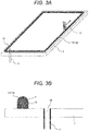
- Figure 3A is a perspective view showing a process of applying encapsulating material paste.
- Figure 3B is a partially enlarged sectional view of Figure 3A .
- Figure 4A is a perspective view showing a state of forming a heat ray reflecting film and spacers.
- Figure 4B is a sectional view of Figure 4A .
- Figure 5A is a sectional view showing a state of combining two glass substrates.
- Figure 5B is a sectional view showing a state of fixing two glass substrates.
- Figure 6A is a sectional view showing a process of depressurizing an interior space of a vacuum multilayered glass panel.
- Figure 6B is a partially enlarged sectional view of Figure 6A .
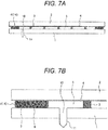
- Figure 7A is a sectional view showing a state of sealing an interior space of a vacuum multilayered glass panel.
- Figure 7B is a partially enlarged sectional view of Figure 7A .
- Figure 8A is a graph showing a temperature profile in a process of removing a binder resin in encapsulating material paste.
- Figure 8B is a graph showing a temperature profile when a seal part is heated in a process of depressurizing an interior space of a vacuum multilayered glass panel.
- encapsulating material paste 13 is applied with a dispenser 12 to a periphery of the first glass substrate 1 where an exhaust hole 10 and an exhaust pipe 11 are installed. Then the encapsulating material paste 13 is dried at about 150°C for 30 minutes over a hotplate and a solvent in the encapsulating material paste 13 is evaporated and removed.
- a binder resin in the encapsulating material paste is decomposed and removed through a temperature profile shown in Figure 8A .
- an encapsulating material 14 is formed by being baked over the first glass substrate 1 by softening and fluidizing the particles of the low melting glass 7 contained in the encapsulating material paste 13.
- a heating rate and a cooling rate are set to 2°C/min. in the atmosphere as shown in Figure 8A .
- the binder resin is decomposed and removed by once retaining a certain temperature T 1 between a yield point M g and a softening point T s of the low melting glass 7 for about 30 minutes.
- the encapsulating material 14 is formed at the periphery of the first glass substrate 1 by raising the temperature again and retaining a certain temperature T 2 that is higher than the softening point T s by 20°C to 40°C for about 30 minutes.
- the encapsulating material paste 13 changes to the encapsulating material 14 through the above processes.
- a heat ray reflecting film 6 is formed over a whole one surface of the second glass substrate 2 by a vapor deposition method as shown in Figures 4A and 4B . Then, many spacers 3 are attached over the surface of the heat ray reflecting film 6.
- first glass substrate 1 and the second glass substrate 2 manufactured through the above processes are put together so as to face each other as shown in Figure 5A . Then, they are fixed with heat resistant clips 15 or the like as shown in Figure 5B .
- the clipped first glass substrate 1 and second glass substrate 2 are placed inside a vacuum exhaust furnace 16, an electric heater 17 is attached to an exhaust pipe 11, and the exhaust pipe 11 is connected to a vacuum pump 18 as shown in Figure 6A .
- the exhaust pipe 11 is burnt off with the electric heater 17 during cooling or after cooling so that the vacuum state of the interior space 5 may be retained as shown in Figures 7A and 7B .
- Table 1 shows the compositions and characteristics of the experimentally manufactured lead-free low melting glass.
- Table 1 Compositions and characteristics of lead-free low melting glass No. Glass composition (mole %) Density (g/cm 3 ) Characteristic temperature (°C) Thermal expansion coefficient V 2 O 5 TeO 2 Ag 2 O WO 3 BaO K 2 O P 2 O 5 Al 2 O 5 Fe 2 O 3 Y 2 O 3 La 2 O 3 ZnO Transition point T g Yield point M g Softening point T s ( ⁇ 10 -7 /°C) Temperature range (°C) G-01 43.1 31.3 - - - - 15.2 - 10.4 - - - 3.58 294 319 358 102 30-250 G-02 37.8 32.3 - 7.5 22.4 - - - - - - - 4.39 284 303 334 149 G-03 37.7 32.1 - 7.4 17.0 - 5.8 - - - - - 4.23 295 314 3
- Those lead-free low melting glasses G-01 to G-42 are environmentally and safely friendly, as they substantially do not contain harmful lead.
- the glass raw materials were weighed, blended, and mixed to a total of about 200 to 300 g and were put into a platinum crucible or a quartz crucible.
- a crucible was placed in a glass melting furnace (electric furnace), heated to 750°C to 950°C at a heating rate of about 10°C/min, and retained for one hour while being stirred with an alumina stick in order to equalize the molten liquid in the crucible.
- the crucible was taken out from the glass melting furnace, the molten liquid in the crucible was poured over a stainless steel plate, and thus the lead-free low melting glasses G-01 to G-42 shown Table 1 were manufactured respectively.
- G-01 to G-09 that are V 2 O 5 -TeO 2 -based lead-free low melting glasses
- quartz crucibles were used for G-10 to G-42 that are V 2 O 5 -TeO 2 -Ag 2 O-based lead-free low melting glasses, respectively.
- G-01 to G-09 were melted at 950°C
- G-10 to G-19 are melted at 850°C
- G-20 to G-42 were melted at 750°C.
- the densities, characteristic temperatures, and thermal expansion coefficients of the respective experimentally manufactured lead-free low melting glasses G-01 to G-42 were measured.
- the characteristic temperatures were measured by differential thermal analysis (DTA) of glass powder.
- DTA differential thermal analysis
- a microcell type was used so that characteristic points in a DTA curve specific to glass might appear clearly.
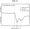
- Figure 9 is a graph showing an example of a typical DTA curve of glass.
- a start temperature of a first endothermic peak is a transition point T g
- the endothermic peak temperature is a yield point M g
- a second endothermic peak temperature is a softening point T s .
- Those characteristic temperatures are obtained generally by a tangent method. The characteristic temperatures are defined by the viscosities of glass respectively and T g is a temperature corresponding to 10 13.3 poise, M g is a temperature corresponding to 10 11.0 poise, and Ts is a temperature corresponding to 10 7.65 poise.
- the experimentally manufactured lead-free low melting glasses G-01 to G-42 were pulverized to an average particle size (D 50 ) of about 1 to 3 ⁇ m by a jet mill and were used for encapsulating material paste.
- an average particle size (D 50 ) of lead-free low melting glass was measured by using a laser diffraction/scattering particle size distribution analyzer LA-950V2 made by HORIBA, Ltd.
- Thales 2 and 3 show low thermal expansion filler particles and spherical glass beads used for encapsulating material paste according to the present invention.
- the low thermal expansion filler particles having an average particle size (D 50 ) of 1 to 15 ⁇ m were used.
- the average particle size (D 50 ) was measured by using a laser diffraction/scattering particle size distribution analyzer LA-950V2 made by HORIBA, Ltd.
- the spherical glass beads are classified to an intended size range with a sieve.
- the average diameter (D 50 ) was measured by using a laser diffraction/scattering particle size distribution analyzer LA-950V2 made by HORIBA, Ltd.
- Encapsulating material paste was manufactured by using the particles of the lead-free low melting glass in Table 1, the low thermal expansion filler in Table 2, the spherical glass beads in Table 3, a resin binder, and a solvent.
- ethyl cellulose or nitrocellulose was used when the lead-free low melting glasses G-01 to G-09 were used, and aliphatic polycarbonate was used when the lead-free low melting glasses G-10 to G-42 were used.
- a solvent butyl carbitol acetate was used when the lead-free low melting glasses G-01 to G-09 were used and both propylene carbonate and a terpene solvent are used when the lead-free low melting glasses G-10 to G-42 were used.
- a bonded body simulating a seal part of vacuum insulated multilayered glass according to the present invention was manufactured by using encapsulating material paste according to the present invention and the reliability of the bonded part was evaluated.
- encapsulating material paste according to the present invention was used, two glass substrates were bonded, and the bond strength of a bonded body was evaluated by shear stress.
- encapsulating material paste not including the spherical glass beads was used and on the basis of this the effectiveness of including the glass beads was confirmed.
- a manufacturing method of a bonded body according to the present example is shown in Figures 10A to 11B .
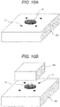
- Figure 10A is a schematic perspective view showing a state of placing encapsulating material paste and spacers over a glass substrate, which is a part of a manufacturing method of a bonded body simulating a seal part of a vacuum insulated multilayered glass panel.
- Figure 10B is a schematic perspective view showing a process of stacking another glass substrate over the glass substrate in Figure 10A .
- Figure 11A is a schematic sectional view showing a process of pressing the two glass substrates after the process in Figure 10B .
- Figure 11B is a schematic sectional view showing a state of completing the process in Figure 11A .
- glass substrates 101 and 102 As glass substrates 101 and 102, quite ordinary soda lime glass 5 mm in thickness was used.
- the size of the glass substrate 101 is 20 ⁇ 20 mm square and the size of the glass substrate 102 was 10 ⁇ 10 mm square.
- encapsulating material paste 13 was applied over the upper surface of the glass substrate 101 so as to have a diameter of 5 mm and a thickness of about 500 to 600 ⁇ m. Further, four metal-made spacers 3 having 220 ⁇ m in height were placed. After they were dried at 150°C for 30 minutes, the glass substrate 102 was put together as shown in Figure 10B .
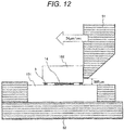
- Figure 12 shows a configuration of an apparatus to measure a bond strength of a bonded body obtained by the above manufacturing method.
- a bonded body is fixed to a bonded body fixing jig 52, the bonded body including glass substrates 101 and 102; and an encapsulating material 14 and spacers 3 interposed between the substrates. Then, external force is applied laterally to the glass substrate 102 by a shear jig 51. On this occasion, the lower end of the shear jig 51 is adjusted so as to be positioned 500 ⁇ m apart from the upper surface of the glass substrate 101. Further, the moving speed of the shear jig 51 is set to 34 ⁇ m/sec.
- the encapsulating material paste used in the present example includes the lead-free low melting glasses G-01 to G-42 shown in Table 1, the low thermal expansion filler particles F-01 shown in Table 2, and the spherical glass beads B-14 shown in Table 3 as the solid content.
- the volume fractions of the lead-free low melting glasses G-01 to G-42 and the low thermal expansion filler particles F-01 in the solid content were decided in consideration of the thermal expansion of the soda lime glass used for the glass substrates 101 and 102. Further, the volume fraction of the spherical glass beads B-14 in the solid content was set to 20% to 30% by volume. In this way, five bonded bodies for each were manufactured as the present example, and an average bond strength was obtained.
- Table 4 shows volume fractions of the solid content in encapsulating material paste, the bonding conditions, and the bond strength improvement rates of the manufactured bonded bodies.
- the bond strength improvement rates of the bonded bodies A-01 to A-42 are values based on a bonded body not including the spherical glass beads B-14 in the solid content.
- the bond strength improvement rates of the bonded bodies A-01 to A-42 are values calculated by using an average bond strength of the bonded bodies of the comparative example as a denominator and a value obtained by subtracting the average bond strength of the bonded bodies of the comparative example from an average bond strength of the bonded bodies of the present example as a numerator.
- any of the bonded bodies had an average bond strength of about 10 to 20 MPa in terms of shear stress. Further, in the range, an average bond strength tended to increase as lead-free low melting glass of a higher softening point T s was used.
- Table 4 Solid content volume fractions in encapsulating material paste, bonding conditions, and bond strength improvement rate of manufactured bonded body Bonded body No.
- any of the bonded bodies A-01 to A-42 in the present example including the spherical glass beads B-14 has an average bond strength improved from the comparative example.
- any of the bonded bodies was in the state of vertically separating the encapsulating material 14 shown in Figure 12 , in other words, a nearly center part in the bond thickness of 220 ⁇ m broke in most cases.
- a broken part of the bonded bodies A-01 to A-42 in the present example including the spherical glass beads B-14 was observed, in any of the bonded bodies, it could be seen that cracks were inhibited from propagating in the encapsulating material 14 by the existence of the spherical glass beads B-14. This is thought to be the reason why the bond strength improved.
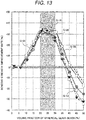
- the ratio of the volume fractions of the lead-free low melting glasses G-08, G-10, G-25, G-36, and G-42 and the low thermal expansion filler particles F-01 was kept constant in consideration of the thermal expansion of glass substrates 101 and 102 similarly to Example 1 and the volume fraction of the spherical glass beads B-14 was changed. Since the thermal expansion coefficients of the lead-free low melting glasses G-25, G-36, and G-42 are larger than those of G-08 and G-10, it is necessary to reduce the volume fraction of the lead-free low melting glass but increase the volume fraction of the low thermal expansion filler particles in order to conform to the thermal expansion of the glass substrates 101 and 102.
- Figure 13 is a graph showing a relationship between a bond strength improvement rate of a bonded body and a volume fraction of spherical glass beads B-14 in a solid content in encapsulating material paste.
- the effect of bond strength improvement is scarcely recognized when the volume fraction of the spherical glass beads B-14 is less than 10% by volume.
- the bond strength increases as the volume fraction of the glass beads increases when the volume fraction is 10% to 20% by volume, and the maximum value is obtained when the volume fraction is in the range of 20% to 30% by volume.
- the bond strength lowers when the volume fraction exceeds 30% by volume.
- the bond strength improvement rate took a positive value and the bond strength was larger than the case of not including the spherical glass beads B-14.
- the bond strength in the case of using the lead-free low melting glass G-08 or G-10 was almost the same as the case of not including the spherical glass beads B-14, and the bond strength in the case of using the lead-free low melting glass G-25, G-36, or G-10 was lower than the case of not including the spherical glass beads B-14. Further, even when the volume fraction exceeded 40% by volume, the bond strength just simply lowered. A possible reason is thought to be that the volume fraction of the lead-free low melting glass is insufficient in bonding between the glass substrates 101 and 102 and the spherical glass beads.
- the volume fraction of the lead-free low melting glass was smaller in the case of using G-25, G-36, or G-42 than in the case of using G-08 or G-10 as the lead-free low melting glass and the decline rate of the bond strength was large when the volume fraction of the spherical glass beads B-14 exceeds 35% by volume. It is considered that a volume fraction of the lead-free low melting glass in a solid content in encapsulating material paste is required to be at least 35% by volume or more.
- a volume fraction of glass beads is desirably 10% to 35% by volume and particularly 20% to 30% by volume is effective. Further, a volume fraction of lead-free low melting glass is desirably 35% by volume or more. It is inferred easily that this result is effectively reflected in the application of a vacuum insulated multilayered glass panel to low-temperature hermetic sealing.
- the low thermal expansion filler particles F-01 and F-03 have large negative thermal expansion coefficients. Further, the low thermal expansion fillers F-02 and F-04 have thermal expansion coefficients close to zero. Generally, the smaller the thermal expansion coefficient of low thermal expansion filler particles, the more conformable to the thermal expansion coefficient of glass substrates 101 and 102. Then on such an occasion, it is effective because the volume fraction of the lead-free low melting glass can be increased. Thinking like this, the low thermal expansion filler particles F-03 having the smallest thermal expansion coefficient in Table 2 are the most effective low thermal expansion filler particles.
- the wettability of F-03 with any of the V 2 O 5 -TeO 2 -based and V 2 O 5 -TeO 2 -Ag 2 O-based lead-free low melting glasses G-01 to G-42 shown in Table 1 is insufficient in comparison with the low thermal expansion filler particles F-01, and hence a dense bonded part is hardly obtained. Further, a desired low thermal expansion coefficient is hardly obtained. Even though spherical glass beads are mixed therefore, expected effect of bond strength improvement is hardly obtained.
- the wettability of the low thermal expansion filler particles F-02 with the V 2 O 5 -TeO 2 -based lead-free low melting glass and the V 2 O 5 -TeO 2 -Ag 2 O-based lead-free low melting glass was good in comparison with the low thermal expansion filler particles F-03 and F-04.
- the thermal expansion coefficient of F-02 is not so small.
- Encapsulating material paste was manufactured by using G-07, G-12, G-24, G-34, and G-39 in Table 1 as the lead-free low melting glass, F-01 in Table 2 as the low thermal expansion filler particles, and B-11 to B-15 in Table 3 as the spherical glass beads.
- the ratio of the volume fractions of the lead-free low melting glasses G-07, G-12, G-24, G-34, and G-39 and the low thermal expansion filler particles F-01 was determined in consideration of the thermal expansion of glass substrates 101 and 102 similarly to Example 1.
- All the spherical glass beads B-11 to B-15 are soda lime glass as shown in Table 3, which is the same raw material as glass substrates 101 and 102.
- the average particle sizes (D 50 ) were 46 ⁇ m in the case of B-11, 88 ⁇ m in the case of B-12, 125 ⁇ m in the case of B-13, 143 ⁇ m in the case of B-14, and 184 ⁇ m in the case of B-15.
- the height 250 ⁇ m of the spacers 3 was determined in consideration of the maximum particle size of the spherical glass beads, specifically the maximum particle size of B-15 having the largest average particle size (D 50 .
- the volume fractions of the spherical glass beads B-11 to B-15 are decided as 30% by volume in the case of using the lead-free low melting glass G07 or G-24, 25% by volume in the case of using G-12, and 20% by volume in the case of using G-34b or G-39.
- Figure 14 is a graph showing a relationship between a bond strength improvement rate of a bonded body and an average particle size (D 50 ) of spherical glass beads contained in encapsulating material paste.
- the numerals in the parentheses [ ] in the figure represent contents of the spherical glass beads by volume.
- an average particle size (D 50 ) of spherical glass beads was effective to set to not less than half of a bond thickness in order to improve the bond strength of a bonded body. Further, it is inferred easily that this result is effectively reflected in the application of a vacuum insulated multilayered glass panel to low-temperature hermetic sealing.
- a distance between two glass substrates namely a height of spacers and a thickness of a seal part, is generally in the range of 100 to 300 ⁇ m, it is appropriate that an average diameter (D 50 ) of spherical glass beads is about not less than 50 ⁇ m to not more than 200 ⁇ m.
- Encapsulating material paste was manufactured by using G-05, G-17, G-33, and G-40 in Table 1 as the lead-free low melting glass, F-01 in Table 2 as the low thermal expansion filler particles, and B-14, B-21, and B-31 in Table 3 as the spherical glass beads.
- the raw materials of the spherical glass beads B-14, B-21, and B-31 were different as shown in Table 3 but the spherical glass beads were classified with the same sieve to the particle size of not less than 75 ⁇ m to less than 212 ⁇ m.
- the respective raw materials of the spherical glass beads are soda lime glass in the case of B-14, borosilicate glass in the case of B-21, and quartz glass in the case of B-31.
- the thermal expansion coefficients of the spherical glass beads are different, in consideration of this in the present example, the volume fractions of the respective solid contents in encapsulating material paste were decided in conformity with the thermal expansion of glass substrates 101 and 102.
- Table 5 shows volume fractions of the solid content in encapsulating material paste, the bonding conditions, and the bond strength improvement rates of the manufactured bonded bodies.
- the bond strength improvement rates of the bonded bodies A-05a to A-05C, A-17a to A-17c, A-33a to A-33c, and A-40a to A-40c are values based on an average bond strength of bonded bodies, which are comparative examples, manufactured by using encapsulating material paste including the lead-free low melting glass G-05, G-17, G-33, or G-40 and the low thermal expansion filler particles F-01 but not including spherical glass beads as the solid content.
- the volume fractions of the lead-free low melting glass and the low thermal expansion filler particles were determined in consideration of the thermal expansion of the soda lime glass used for glass substrate 101 and 102.
- Table 5 Solid content volume fractions in encapsulating material paste, bonding conditions, and bond strength improvement rate of manufactured bonded body Bonded body No.
- any bonded body of the bonded bodies A-05a to A-05C, A-17a to A-17c, A-33a to A-33c, and A-40a to A-40c when the kind of the lead-free low melting glass was the same, the effect of the content of the spherical glass beads B-14 including soda lime glass on bond strength improvement was the largest.
- a secondary effective case was the case of including the spherical glass beads B-21 including borosilicate glass.
- a vacuum insulated multilayered glass panel according to the present invention shown in Figure 1A was manufactured by encapsulating material paste including lead-free low melting glass in Table 1, low thermal expansion filler particles in Table 2, and spherical glass beads in Table 3 and the thermal insulation properties and reliability were evaluated.
- a vacuum insulated multilayered glass panel shown in Figure 1 was manufactured similarly to the above by using encapsulating material paste not including spherical glass beads in Table 3 and the thermal insulation properties and reliability were evaluated.
- the comparative example was used for comparing with the vacuum insulated multilayered glass panel according to the present example.
- the vacuum insulated multilayered glass panels were manufactured in accordance with the manufacturing method of a vacuum insulated multilayered glass panel shown in Figures 3A to 7B and the temperature profiles shown in Figures 8A and 8B .
- soda lime glass substrates of 300 ⁇ 300 ⁇ 3 mm in size were used as the first glass substrate 1 and the second glass substrate 2 and metal-made (stainless steel-made) spacers having 200 ⁇ m in height and 500 ⁇ m in outer diameter were used as the spacers 3.
- the encapsulating material paste used in the present example contains the lead-free low melting glass G-08 in Table 1, the low thermal expansion filler particles F-01 in Table 2, and the spherical glass beads B-13 in Table 3 as solid contents. The respective volume fractions of the solid contents are 48:27:25 (% by volume).
- the encapsulating material paste used in the comparative example contains the lead-free low melting glass G-08 in Table 1 and the low thermal expansion filler particles F-01 in Table 2 as solid contents.
- the respective volume fractions of the solid contents are 64:36 (% by volume).
- the content ratio of the lead-free low melting glass G-08 and the low thermal expansion filler particles F-01 in the comparative example is equivalent to the present example.
- the heat flow rates of both the example and the comparative example were about 0.7 W/m 2 ⁇ K and were good.
- Figure 15 shows a test apparatus used for evaluating reliability of a vacuum insulated multilayered glass panel.
- a test apparatus shown in the present figure is configured so as to place a vacuum insulated multilayered glass panel at a square fluororesin container 19 (formed of PTFE: PolyTetraFluoroEthylene or the like) with a silicon rubber packing 20 interposed; and carry out a test.
- a hot air blower and a cold air blower are installed outside the fluororesin container 19. Two types of air with significantly different temperatures can be sent to the interior of the fluororesin container 19 from either of the hot air blower and the cold air blower through a fluororesin pipe 21 (formed of PTFE or the like) 10 mm in diameter. The temperature of the air can be switched by an automatic on-off valve.
- Hot air of 80°C and cold air of -50°C were blown alternately onto the manufactured vacuum insulated multilayered glass panels according to the present example and the comparative example at a flow rate of 30 L/min for 15 minutes.
- One cycle was regarded as one blow of hot air and one blow of cold air, and the cycle was repeated 1,000 times. Then a damaged state of a seal part was evaluated by measuring a heat flow rate and the like after repeating 1,000 times.
- the seal part did not appear to be damaged in appearance, but leakage occurred somewhere, and no thermal insulation was obtained at all.
- the vacuum insulated multilayered glass panel according to the present example it was confirmed that the primary thermal insulation properties were maintained and the seal part was not damaged. From this, it was clarified that the mixing of spherical glass beads into a seal part was effective.
- the lead-free low melting glass G-12 in Table 1 was used instead of the lead-free low melting glass G-08 in Table 1.
- the other constituent components in the solid content are the low thermal expansion filler particles F-01 in Table 2 and the spherical glass beads B-13 in Table 3.
- a vacuum insulated multilayered glass panel according to the present invention shown in Figure 1A was manufactured by using encapsulating material paste including the solid content and the thermal insulation properties and reliability of the panel were evaluated.
- a vacuum insulated multilayered glass panel shown in Figure 1A was manufactured by using encapsulating material paste excluding the spherical glass beads in Table 3 from the solid content of the present example and the thermal insulation properties and reliability of the panel were evaluated.
- the comparative example was used for comparison with the vacuum insulated multilayered glass panel according to the present example.
- the different point of the vacuum insulated multilayered glass panels according to the present example and the comparative example from Example 5 is that polyimide resin-made spacers having 200 ⁇ m in height and 500 ⁇ m in outer diameter were used as the spacers 3 of the present example.
- spacers 3 in the comparative example metal-made (stainless steel-made) spacers of the same shape were used similarly to Example 5.
- the volume fractions of the lead-free low melting glass G-12, the low thermal expansion filler particles F-01, and the spherical glass beads B-13 in the solid content in the encapsulating material paste used in the present example are 46:29:25 (% by volume). Further, in the encapsulating material paste used in the comparative example, the volume fractions of the lead-free low melting glass G-12 and the low thermal expansion filler particles F-01 in the solid content are 61:39 (% by volume). The content ratio of the lead-free low melting glass G-12 and the low thermal expansion filler particles F-01 in the comparative example is equivalent to the present example.
- the thermal insulation properties of the manufactured vacuum insulated multilayered glass panels according to the present example and the comparative example whereas the heat flow rate of the comparative example was about 0.7 W/m 2 ⁇ K, the heat flow rate of the present example was about 0.5 W/m 2 ⁇ K. That is, the vacuum insulated multilayered glass panel according to the present example showed better thermal insulation properties than the vacuum insulated multilayered glass panel according to the comparative example. This is because resin with significantly lower thermal conductivity than metal was used as the spacers 3.
- the seal part did not appear to be damaged in appearance, but leakage occurred, and the thermal insulation properties deteriorated significantly.
- the vacuum insulated multilayered glass panel according to the present example it was confirmed that the primary thermal insulation properties were maintained and the seal part was not damaged. From this, it was clarified that the mixing of spherical glass beads into a seal part was effective. Further, the effectiveness of the resin-made spacers was recognized.
- Example 5 in the solid content of Example 5, the lead-free low melting glass G-24 in Table 1 and the spherical glass beads B-12 in Table 3 were used instead of the lead-free low melting glass G-08 in Table 1 and the spherical glass beads B-13 in Table 3.
- the other constituent component in the solid content is the low thermal expansion filler particles F-01 in Table 2.
- a vacuum insulated multilayered glass panel according to the present invention shown in Figure 1A was manufactured by using encapsulating material paste including the solid content and the thermal insulation properties and reliability of the panel were evaluated.
- a vacuum insulated multilayered glass panel shown in Figure 1A was manufactured by using encapsulating material paste excluding the spherical glass beads in Table 3 from the solid content of the present example and the thermal insulation properties and reliability of the panel were evaluated.
- the comparative example was used for comparison with the vacuum insulated multilayered glass panel according to the present example.
- the different points of the vacuum insulated multilayered glass panels according to the present example and the comparative example from Example 5 are that air-cool tempered soda lime glass substrates were used as the first glass substrate 1 and the second glass substrate 2 and that polyamide resin-made spacers having 150 ⁇ m in height and 300 ⁇ m in outer diameter were used as the spacers 3 of the present example.
- spacers 3 in the comparative example metal-made (stainless steel-made) spacers of the same shape as the present example were used.
- the volume fractions of the lead-free low melting glass G-24, the low thermal expansion filler particles F-01, and the spherical glass beads B-12 in the solid content in the encapsulating material paste used in the present example are 46:34:20 (% by volume). Further, in the encapsulating material paste used in the comparative example, the volume fractions of the lead-free low melting glass G-24 and the low thermal expansion filler particles F-01 in the solid content are 57:43 (% by volume). The content ratio of the lead-free low melting glass G-12 and the low thermal expansion filler particles F-01 in the comparative example is equivalent to the present example.
- the thermal insulation properties of the manufactured vacuum insulated multilayered glass panels according to the present example and the comparative example whereas the heat flow rate of the comparative example was about 0.8 W/m 2 ⁇ K, the heat flow rate of the present example was about 0.6 W/m 2 ⁇ K. That is, the vacuum insulated multilayered glass panel according to the present example showed better thermal insulation properties than the vacuum insulated multilayered glass panel according to the comparative example. This is because resin with significantly lower thermal conductivity than metal is used as the spacers 3.
- Example 5 in the solid content of Example 5, the lead-free low melting glass G-25 in Table 1 and the spherical glass beads B-15 in Table 3 were used instead of the lead-free low melting glass G-08 in Table 1 and the spherical glass beads B-13 in Table 3.
- the other constituent component in the solid content is the low thermal expansion filler particles F-01 in Table 2.
- a vacuum insulated multilayered glass panel according to the present invention shown in Figure 1A was manufactured by using encapsulating material paste including the solid content and the thermal insulation properties and reliability of the panel were evaluated.
- a vacuum insulated multilayered glass panel shown in Figure 1A was manufactured by using encapsulating material paste excluding the spherical glass beads in Table 3 from the solid content of the present example and the thermal insulation properties and reliability of the panel were evaluated.
- the comparative example was used for comparison with the vacuum insulated multilayered glass panel according to the present example.
- the different points of the vacuum insulated multilayered glass panels according to the present example and the comparative example from Example 5 are that a chemically tempered soda lime glass substrate was used as the first glass substrate 1 and the second glass substrate 2 and that fluororesin spacers including ceramic particles having 250 ⁇ m in height and 500 ⁇ m in outer diameter were used as the spacers 3 of the present example.
- the ceramic particles are Al 2 O 3 particles.
- the ceramic particles are dispersed in resin spacers so that the resin spacers might not deform during hermetic sealing.
- spacers 3 in the comparative example metal-made (stainless steel-made) spacers of the same shape as the present example were used.
- the volume fractions of the lead-free low melting glass G-25, the low thermal expansion filler particles F-01, and the spherical glass beads B-15 in the solid content in the encapsulating material paste used in the present example are 40:30:30 (% by volume). Further, in the encapsulating material paste used in the comparative example, the volume fractions of the lead-free low melting glass G-25 and the low thermal expansion filler particles F-01 in the solid content are 57:43 (% by volume). The content ratio of the lead-free low melting glass G-25 and the low thermal expansion filler particles F-01 in the comparative example is equivalent to the present example.
- the thermal insulation properties of the manufactured vacuum insulated multilayered glass panels according to the present example and the comparative example whereas the heat flow rate of the comparative example was about 0.7 W/m 2 ⁇ K, the heat flow rate of the present example was about 0.4 W/m 2 ⁇ K. That is, the vacuum insulated multilayered glass panel according to the present example showed better thermal insulation properties than the vacuum insulated multilayered glass panel according to the comparative example. This is because resin with significantly lower thermal conductivity than metal was used as the spacers 3.
- the lead-free low melting glass G-22 in Table 1 was used instead of the lead-free low melting glass G-08 in Table 1.
- the other constituent components in the solid content are the low thermal expansion filler particles F-01 in Table 2 and the spherical glass beads B-13 in Table 3.
- Two types of vacuum insulated multilayered glass panels according to the present invention shown in Figure 1A were manufactured by using encapsulating material paste including the solid content while the material of the spacers 3 is changed and the thermal insulation properties and reliability of the panels were evaluated.
- a vacuum insulated multilayered glass panel shown in Figure 1A was manufactured by using encapsulating material paste excluding the spherical glass beads in Table 3 from the solid content of Example 5 and the thermal insulation properties and reliability of the panel were evaluated.
- the comparative example was used for comparison with the vacuum insulated multilayered glass panels according to the present example.
- the different point of the vacuum insulated multilayered glass panels according to the present example and the comparative example from Example 5 is that two types of spacers including epoxy resin including glass particles and phenoxy resin including glass particles, having 200 ⁇ m in height and 500 ⁇ m in outer diameter, were used as the spacers 3 of the present example.
- the glass particles are SiO 2 particles.
- the glass particles were dispersed in resin spacers so that the resin spacers might not deform during hermetic sealing.
- spacers 3 in the comparative example metal-made (stainless steel-made) spacers of the same shape as the present example were used.
- the volume fractions of the lead-free low melting glass G-22, the low thermal expansion filler particles F-01, and the spherical glass beads B-13 in the solid content in the encapsulating material paste used in the present example are 42:38:20 (% by volume). Further, in the encapsulating material paste used in the comparative example, the volume fractions of the lead-free low melting glass G-22 and the low thermal expansion filler particles F-01 in the solid content are 53:47 (% by volume). The content ratio of the lead-free low melting glass G-22 and the low thermal expansion filler particles F-01 in the comparative example is equivalent to the present example.
- the thermal insulation properties of the manufactured vacuum insulated multilayered glass panels according to the present example and the comparative example whereas the heat flow rate of the comparative example was about 0.8 W/m 2 ⁇ K, the heat flow rate of the present example was about 0.5 W/m 2 ⁇ K in both the two types. That is, the vacuum insulated multilayered glass panels according to the present example showed better thermal insulation properties than the vacuum insulated multilayered glass panel according to the comparative example. This is because resin with significantly lower thermal conductivity than metal was used as the spacers 3.
- the lead-free low melting glass G-42 in Table 1 was used instead of the lead-free low melting glass G-08 in Table 1.
- the other constituent components in the solid content are the low thermal expansion filler particles F-01 in Table 2 and the spherical glass beads B-13 in Table 3.
- a vacuum insulated multilayered glass panel according to the present invention shown in Figure 1A was manufactured by using encapsulating material paste including the solid content and the thermal insulation properties and reliability of the panel were evaluated.
- a vacuum insulated multilayered glass panel shown in Figure 1A was manufactured by using encapsulating material paste excluding the spherical glass beads in Table 3 from the solid content of the present example and the thermal insulation properties and reliability of the panel were evaluated.
- the comparative example was used for comparison with the vacuum insulated multilayered glass panel according to the present example.
- the different points of the vacuum insulated multilayered glass panels according to the present example and the comparative example from Example 5 are that air-cool tempered soda lime glass substrates were used as the first glass substrate 1 and the second glass substrate 2 and that silicon resin spacers including glass particles having 200 ⁇ m in height and 500 ⁇ m in outer diameter were used as the spacers 3 of the present example.
- the glass particles are SiO 2 particles.
- the glass particles were dispersed in resin spacers so that the resin spacers might not deform during hermetic sealing.
- spacers 3 in the comparative example metal-made (stainless steel-made) spacers of the same shape as the present example were used.
- the volume fractions of the lead-free low melting glass G-42, the low thermal expansion filler particles F-01, and the spherical glass beads B-13 in the solid content in the encapsulating material paste used in the present example are 43:32:25 (% by volume). Further, in the encapsulating material paste used in the comparative example, the volume fractions of the lead-free low melting glass G-42 and the low thermal expansion filler particles F-01 in the solid content are 57:43 (% by volume). The content ratio of the lead-free low melting glass G-42 and the low thermal expansion filler particles F-01 in the comparative example is equivalent to the present example.
- the thermal insulation properties of the manufactured vacuum insulated multilayered glass panels according to the present example and the comparative example whereas the heat flow rate of the comparative example was about 0.7 w/m 2 ⁇ K, the heat flow rate of the present example was about 0.4 W/m 2 ⁇ K. That is, the vacuum insulated multilayered glass panel according to the present example showed better thermal insulation properties than the vacuum insulated multilayered glass panel according to the comparative example. This is because resin with significantly lower thermal conductivity than metal was used as the spacers 3.
- a vacuum insulated multilayered glass panel according to the present invention can achieve hermetic sealing at a low temperature and hence is excellent also in mass productivity. Moreover, resin of low thermal conductivity can be used for spaces and hence the thermal insulation properties are also excellent. Further, the bond strength of a seal part can be improved and hence reliability is also excellent. The mass productivity, thermal insulation properties, and reliability can be realized by encapsulating material paste according to the present invention.
- a vacuum insulated multilayered glass panel according to the present invention to which encapsulating material paste according to the present invention is applied can be spread widely in housing and construction fields around the world, reduces CO 2 emissions by reducing energy consumption, and can contribute largely to global warming countermeasures.
Landscapes
- Chemical & Material Sciences (AREA)
- Engineering & Computer Science (AREA)
- Chemical Kinetics & Catalysis (AREA)
- General Chemical & Material Sciences (AREA)
- Geochemistry & Mineralogy (AREA)
- Materials Engineering (AREA)
- Organic Chemistry (AREA)
- Life Sciences & Earth Sciences (AREA)
- Structural Engineering (AREA)
- Civil Engineering (AREA)
- Ceramic Engineering (AREA)
- Physics & Mathematics (AREA)
- Thermal Sciences (AREA)
- Dispersion Chemistry (AREA)
- Crystallography & Structural Chemistry (AREA)
- Joining Of Glass To Other Materials (AREA)
- Glass Compositions (AREA)
- Securing Of Glass Panes Or The Like (AREA)
- Structures Or Materials For Encapsulating Or Coating Semiconductor Devices Or Solid State Devices (AREA)
Abstract
Description
- The present invention relates to an encapsulating material and a multilayered glass panel using the encapsulating material.
- In recent years, window glass with much higher thermal insulation than conventional multilayered glass windows has been required. In order to achieve this, high thermal insulation by high vacuum in the interior of a multilayered glass window is essential. In order to spread it worldwide, it is necessary to advance development with due consideration for manufacturing costs, etc. of a multilayered glass window.
- When trying to achieve high vacuum in the interior of a multilayered glass window panel, it is necessary to increase the number of spacers to secure a space inside the panel. A cylindrical metal is generally used for the spacers. Since metal has high thermal conductivity, however, a possible arising inconsistent problem is that if the number of spacers is increased, thermal insulation will be reduced even if the degree of vacuum is increased.
- It is conceivable to use ceramics or glass having lower thermal conductivity than metal for spacers. Ceramics or glass, however, is a material harder than metal. Panel glass therefore may be damaged and a vacuum insulated multilayered glass panel may be destroyed.
- Resin has low thermal conductivity and hence is effectively applied to spacers instead of metal, ceramics, and glass. On the other hand, since resin has a lower thermal resistance than metal, ceramics, and glass, however, it is necessary to apply hermetic sealing at a low temperature lower than a heatproof temperature. When resin is used for spacers therefore, it is difficult to apply a conventional lead-based low melting glass or bismuth-based low melting glass having a high sealing temperature.
- Further, for prevention of damage due to high vacuum, safety, crime prevention, etc., application of a tempered glass that hardly breaks by applying an air-cool tempering treatment or the like to a panel glass is required. The tempered glass achieves high strength by forming a compression strengthened layer over the surface. However, a strengthened layer of the conventional lead-based low melting glass or bismuth-based low melting glass reduces gradually at a heating temperature of about 320°C or higher and disappears at about 400°C or higher. With the conventional lead-based low melting glass or bismuth-based low melting glass having a sealing temperature of 400°C or higher, therefore, it is difficult to apply the tempered glass to the panel glass.
- As stated above, in order to achieve high vacuum in the interior of a panel and high thermal insulation of the panel in a vacuum insulated multilayered glass panel, it is very important to lower a sealing temperature.
-
PTL 1 discloses a lead-free low melting glass composition including Ag2O of 10% to 60% by mass, V2O5 of 5% to 65% by mass, and TeO2 of 15% to 50% by mass when the components are represented by oxides, in which: a total content of Ag2O, V2O5, and TeO2 is not less than 75% by mass to less than 100% by mass; and the balance includes at least one kind of P2O5, BaO, K2O, WO3, Fe2O3, MnO2, Sb2O3, and ZnO of more than 0% by mass to not more than 25% by mass. The Ag2O-V2O5-TeO2-based lead-free low melting glass has a softening point in the temperature range of 268°C to 320°C, and softens and fluidizes at a much lower temperature than a conventional lead-based or bismuth-based low melting glass. -
PTL 2 discloses a glass sealing material including vanadium-based (V2O5-P2O5-based) low melting glass (vanadium phosphate glass) and filler particles, the low melting glass being applicable as a sealing material of a glass panel for a flat panel display, not devitrifying during a sealing process, and being able to obtain a high bond strength. The glass sealing material further includes glass beads of 0.1% to 1.0% by volume. Here, the glass beads function as an aggregate for attaching two panel glasses at equal intervals. -
- PTL 1: Japanese Patent Application Laid-Open No.
2013-32255 - PTL 2: Japanese Patent Application Laid-Open No.
2007-320822 - The glass composition disclosed in
PTL 1 enables hermetic sealing at a low temperature of 320°C or lower. The mechanical strength of a seal part, however, tends to deteriorate as a sealing temperature lowers. There is room, therefore, for improvement in the reliability of the seal part. - The vanadium phosphate glass disclosed in
PTL 2 has a softening point of around 400°C and a fluidizing point of about 450°C to 500°C, and hence the improvement of the mechanical strength of a seal part with lowering of a sealing temperature has not been sufficiently studied. - An object of the present invention is to provide a highly reliable multilayered glass panel and an encapsulating material for achieving the highly reliable multilayered glass panel.
- An encapsulating material according to the present invention includes lead-free low melting glass particles containing vanadium oxide and tellurium oxide, low thermal expansion filler particles, and glass beads as a solid content, in which a volume fraction of the glass beads in the solid content is not less than 10% to not more than 35%; and a volume fraction of the lead-free low melting glass particles in the solid content is larger than a volume fraction of the low thermal expansion filler in the solid content.
- The present invention makes it possible to provide a highly reliable multilayered glass panel and an encapsulating material for achieving the highly reliable multilayered glass panel.
-
-
Figure 1A is a schematic perspective view showing a typical vacuum insulated multilayered glass panel. -
Figure 1B is a sectional view of the vacuum insulated multilayered glass panel inFigure 1A and an enlarged sectional view showing a seal part. -
Figure 2 is an enlarged sectional view showing a seal part of a vacuum insulated multilayered glass panel according to an embodiment. -
Figure 3A is a schematic perspective view showing a process of applying encapsulating material paste, which is a part of a manufacturing method of a vacuum insulated multilayered glass panel according to an embodiment. -
Figure 3B is an enlarged sectional view showing a periphery of the vacuum insulated multilayered glass panel inFigure 3A . -
Figure 4A is a schematic perspective view showing a process of forming a heat ray reflecting film and spacers, which is a part of a manufacturing method of a vacuum insulated multilayered glass panel according to an embodiment. -
Figure 4B is a schematic sectional view ofFigure 4A . -
Figure 5A is a schematic sectional view showing a state of stacking two glass substrates, which is a part of a manufacturing method of a vacuum insulated multilayered glass panel according to an embodiment. -
Figure 5B is a schematic sectional view showing a state of fixing two glass substrates, which is a part of a manufacturing method of a vacuum insulated multilayered glass panel according to an embodiment. -
Figure 6A is a schematic sectional view showing a process of depressurizing an interior space of a vacuum multilayered glass panel, which is a part of a manufacturing method of a vacuum insulated multilayered glass panel according to an embodiment. -
Figure 6B is a partially enlarged sectional view showing a vicinity of the seal part inFigure 6A . -
Figure 7A is a schematic sectional view showing a state of sealing an interior space of a vacuum multilayered glass panel, which is a part of a manufacturing method of a vacuum insulated multilayered glass panel according to an embodiment. -
Figure 7B is a partially enlarged sectional view showing a vicinity of the seal part inFigure 7A . -
Figure 8A is a graph showing a temperature profile in a process of removing a binder resin in encapsulating material paste. -
Figure 8B is a graph showing a temperature profile when the seal part is heated in a process of depressurizing an interior space of a vacuum multilayered glass panel. -
Figure 9 is a graph showing an example of a typical differential thermal analysis curve (DTA curve) specific to glass. -
Figure 10A is a schematic perspective view showing a state of placing encapsulating material paste and spacers over a glass substrate, which is a part of a manufacturing method of a bonded body simulating a seal part of a vacuum insulated multilayered glass panel. -
Figure 10B is a schematic perspective view showing a process of stacking another glass substrate over the glass substrate inFigure 10A . -
Figure 11A is a schematic sectional view showing a process of pressing the two glass substrates after the process inFigure 10B . -
Figure 11B is a schematic sectional view showing a state of completing the process inFigure 11A . -
Figure 12 is a schematic sectional view showing a part of a bond strength test apparatus for a bonded body simulating a seal part of a vacuum insulated multilayered glass panel. -
Figure 13 is a graph showing a relationship between a bond strength improvement rate of a bonded body simulating a seal part of a vacuum insulated multilayered glass panel and a volume fraction of spherical glass beads in a solid content in encapsulating material paste. -
Figure 14 is a graph showing a relationship between a bond strength improvement rate of a bonded body simulating a seal part of a vacuum insulated multilayered glass panel and an average particle size (D50) of spherical glass beads in a solid content in encapsulating material paste. -
Figure 15 is a schematic sectional view showing a reliability test apparatus for a vacuum insulated multilayered glass panel. - Embodiments according to the present invention are explained hereunder in reference to the drawings. The present invention, however, is not limited to the embodiments featured here and can be combined or improved appropriately in the range not changing the tenor of the present invention.
- A vacuum insulated multilayered glass panel (merely referred to also as "multilayered glass panel") applied to window glass for a building material or the like has an interior space between two glass substrates with many spacers interposed. The interior space is in a vacuum state and further the periphery of the two glass substrates is sealed hermetically in order to retain the vacuum state for a long period of time. An encapsulating material including a low melting glass and low thermal expansion filler particles is applied to the hermetic sealing of the periphery, and the hermetically sealed part is in the state of dispersing the low thermal expansion filler in the low melting glass. Further, a distance between the two glass substrates, namely a height of the spacers and a thickness of the hermetically sealed part, is usually in the range of 100 to 300 µm in the vacuum insulated multilayered glass panel.
-
Figure 1A is a schematic perspective view showing a typical vacuum insulated multilayered glass panel. -
Figure 1B is a sectional view corresponding toFigure 1A and is a view enlarging and showing a hermetical seal part. - In
Figure 1A , a vacuum insulated multilayered glass panel has afirst glass substrate 1, and asecond glass substrate 2 as well asspacers 3 and aseal part 4 which are interposed between the substrates. Theseal part 4 is formed at a periphery of thefirst glass substrate 1 and thesecond glass substrate 2. - Further, as shown in
Figure 1B , theinterior space 5 is formed in the region surrounded by thefirst glass substrate 1, thesecond glass substrate 2, and theseal part 4. A heatray reflecting film 6 is attached over the inner surface of thesecond glass substrate 2.Multiple spacers 3 are placed and support thefirst glass substrate 1 and thesecond glass substrate 2 so that a distance between thefirst glass substrate 1 and thesecond glass substrate 2 may be a predetermined value. Generally it is desirable that the distance is constant. - In the vacuum insulated multilayered glass panel, a soda lime glass substrate having a thermal expansion coefficient in the range of 80 to 90 × 10-7/°C is generally used for the
first glass substrate 1 and thesecond glass substrate 2. - As shown in the enlarged view of
Figure 1B , theseal part 4 includeslow melting glass 7 and low thermalexpansion filler particles 8. The low thermalexpansion filler particles 8 are dispersed in thelow melting glass 7. A vacuum state of theinterior space 5 is realized by theseal part 4 and is retained on a long-term basis. The low thermalexpansion filler particles 8 are mixed for conforming the thermal expansion coefficient of theseal part 4 to the thermal expansion coefficient of thefirst glass substrate 1 and thesecond glass substrate 2. - The heat
ray reflecting film 6 is effective when the vacuum insulated multilayered glass panel is applied to window glass for a building material and is used generally. - In such a vacuum insulated multilayered glass panel, a sealing temperature is almost determined by the softening and fluidizing characteristics at a heating temperature of the
low melting glass 7 use for theseal part 4. In other words, a sealing temperature can be lowered as thelow melting glass 7 of a lower softening point is used. In contrast, however, mechanical strength tends to lower as thelow melting glass 7 of a lower softening point is used. Further, on this occasion, a thermal expansion coefficient tends to increase. To cope with this, it is necessary to increase a volume fraction of the low thermalexpansion filler particles 8 contained in theseal part 4. -
Figure 2 is a view enlarging and showing a cross section of a seal part in a typical vacuum insulated multilayered glass panel according to an embodiment. - A different point in
Figure 2 from the enlarged view ofFigure 1B is thatspherical glass beads 9 are also dispersed inlow melting glass 7. - The low melting glass 7 (lead-free low melting glass) contains vanadium oxide (V2O5) and tellurium oxide (TeO2). By this composition, a sealing temperature can be lower than 400°C.
- A volume fraction of the
glass beads 9 is not less than 10% to not more than 35%. A volume fraction of thelow melting glass 7 is larger than a volume fraction of the low thermalexpansion filler particles 8. - By controlling the volume fraction of the
glass beads 9 in the above range, it is possible to prevent cohesive failure at theseal part 4 and improve mechanical strength. As a result, the reliability of a vacuum insulated multilayered glass panel can be secured. If the volume fraction of theglass beads 9 is less than 10%, the improvement of mechanical strength is scarcely seen. In contrast, if the volume fraction of theglass beads 9 exceeds 35%, theseal part 4 is likely to peel off from an interface with thefirst glass substrate 1 or thesecond glass substrate 2. Here, the volume fraction of theglass beads 9 is desirably not less than 20% to not more than 30%. - Further, when the
low melting glass 7 contains silver oxide (Ag2O), the sealing temperature can be lower than 320°C. As a result, a resin having low thermal conductivity can be applied to thespacers 3. Further, a tempered glass subjected to an air-cool tempering treatment or a chemical tempering treatment can be applied to thefirst glass substrate 1 and thesecond glass substrate 2. Further, by lowering the sealing temperature, it is possible to improve mass productivity of a vacuum insulated multilayered glass panel, reduce mass production capital investment, and contribute to the reduction of manufacturing costs. - With regard to the size of
glass beads 9, the maximum diameter has to be not more than a distance between thefirst glass substrate 1 and thesecond glass substrate 2. Further, an average diameter (D50) is desirably not less than half of the distance. Here, the average diameter (D50) is a median diameter and is also referred to as "average particle size". An average particle size (D50) of theglass beads 9 can be obtained by, for example, classifying theglass beads 9 with a sieve and successively measuring theglass beads 9 by a laser diffraction/scattering particle size distribution analyzer. - It is desirable that the
glass beads 9 are the same or similar glass system as thefirst glass substrate 1 and thesecond glass substrate 2. This is because the thermal expansion characteristics are the same or close and this makes it possible to stably improve the mechanical strength of the seal part. - Specifically, it is desirable to use glass beads of soda lime glass (SiO2-Na2O-CaO-based glass), borosilicate glass (SiO2-B2O3-Na2O-based glass), quartz glass (SiO2), or the like.
- Meanwhile, in the present description, glass beads are defined as nearly spherical glass. Further, in a vacuum insulated multilayered glass panel, low thermal
expansion filler particles 8 are mixed in order to conform the thermal expansion of theseal part 4 to the thermal expansion of thefirst glass substrate 1 and thesecond glass substrate 2 but, if the volume fraction of the low thermalexpansion filler particles 8 is not less than the volume fraction of thelow melting glass 7, the softening and fluidizing characteristics of thelow melting glass 7 during heating and sealing deteriorate, and hermetic sealing is hardly obtained. The volume fraction of thelow melting glass 7, therefore, has to be larger than the volume fraction of the low thermalexpansion filler particles 8. More desirably, it is effective to control the volume fraction of thelow melting glass 7 to not less than 35%. Further, the volume fraction of thelow melting glass 7 is desirably not more than 72%. - When the
low melting glass 7 further contains at least one kind of tungsten oxide (WO3), barium oxide (BaO), potassium oxide (K2O), and phosphorous oxide (P2O5) as a glass component, vitrification can be facilitated during glass production. By such a composition, it is possible to reduce the crystallization tendency of the manufacturedlow melting glass 7. If the crystallization tendency of thelow melting glass 7 is large, arising problems are that crystallization occurs during heating and sealing, good softening and fluidizing characteristics are not obtained, and high airtightness is not obtained at theseal part 4. - It is effective to further contain at least one kind of aluminum oxide (Al2O3), iron oxide (Fe2O3), yttrium oxide (Y2O3), and lanthanum oxide (La2O3) as a glass component. Those components contribute to the prevention or significant suppression of crystallization even with small quantities. As a result, a highly
hermetic seal part 4 is obtained. - As the low thermal
expansion filler particles 8, a substance including zirconium phosphate tungstate (Zr2(WO4) (PO4)2), quartz glass, β-eucryptite, or cordierite can be used, for example. - Among those materials, zirconium phosphate tungstate is effective. Zirconium phosphate tungstate has a large negative thermal expansion and the thermal expansion coefficient is -40 × 10-7/°C. Further, since the low thermal
expansion filler particles 8 have good wettability and adhesiveness with thelow melting glass 7, the effect of low thermal expansion is large and the characteristic of easily conforming the thermal expansion of theseal part 4 to the thermal expansion of a glass substrate can be obtained. It is desirable that the average particle size (D50) of the low thermal expansion filler is not less than 3 µm to not more than 20 µm. By controlling the average particle size (D50) of the low thermal expansion filler to not less than 3 µm to not more than 20 µm, it is possible to inhibit cracks from occurring at an interface and obtain the effect of thermal expansion coefficient adjustment. Here, the average particle size (D50) of the low thermal expansion filler can be measured by a laser diffraction/scattering particle size distribution analyzer. - When lead-free low melting glass containing vanadium oxide (V2O5), tellurium oxide (TeO2), and silver oxide (Ag2O) is used for a seal part in particular, the sealing temperature can be lowered, and hence a resin of low thermal conductivity can be applied to the
spacers 3. Specific examples of resin are polyimide resin, polyamide resin, fluororesin, epoxy resin, phenoxy resin, and silicone resin. - In general, resin is softer than metal, ceramics, and glass, and hence the resin never damages or destroys the
first glass substrate 1 and thesecond glass substrate 2 when resin is used for thespacers 3. Otherwise, when hardness is required as thespacers 3, glass particles or ceramic particles may be dispersed as a filler in a resin. - A vacuum insulated multilayered glass panel according to the present embodiment is excellent in thermal insulation properties, mass productivity, and reliability, and hence is effectively applicable particularly to window glass for a building material. Moreover, a vacuum insulated multilayered glass panel according to the present embodiment is easy to spread widely in housing and construction fields around the world. As a result, it can reduce CO2 emissions by reducing energy consumption and contribute to global warming countermeasures. Further, the vacuum insulated multilayered glass panel can also apply to other than window glass for a building material and can apply widely to a part or a product such as vehicle window glass and a door of a commercial refrigerator or freezer which require thermal insulation properties.
- The
seal part 4 of a vacuum insulated multilayered glass panel shown inFigure 2 is generally formed by using encapsulating material paste. The encapsulating material paste includes particles of thelow melting glass 7 containing vanadium oxide (V2O5) and tellurium oxide (TeO2), the low thermalexpansion filler particles 8, theglass beads 9, a binder resin, and a solvent. - Meanwhile, in this description, explanations are made on the premise that a solid content in the constituent components of such encapsulating material paste is the
low melting glass 7, the low thermalexpansion filler particles 8, and theglass beads 9. The reason is that the binder resin and the solvent vaporize during drying and baking and are not substantially contained in a completedseal part 4. - Further, a volume fraction in a solid content is calculated by using a sum of true volumes of the three constituent components in the solid content as a reference (denominator). This is because the
seal part 4 is thought substantially not to have a void. In the present description, description of "volume fraction" related to "solid content" represents "a volume fraction in a solid content" even in the case of being merely described as "a volume fraction". A volume fraction is a fraction based on a volume and the unit is % by volume. Here, in the present description, % by volume may be represented merely as "%" in some cases. - A volume fraction of the
glass beads 9 in the solid content is not less than 10% to not more than 35%. Further, it is desirable that a volume fraction of the particles of thelow melting glass 7 in the solid content is larger than a volume fraction of the low thermalexpansion filler particles 8 in the solid content. - Further, the size of the
glass beads 9 in the solid content is appropriately not less than 50 µm to not more than 200 µm in terms of an average diameter (D50) of theglass beads 9 in consideration of a distance between thefirst glass substrate 1 and thesecond glass substrate 2 in a vacuum insulated multilayered glass panel, namely a height of thespacers 3 and a thickness of theseal part 4. The reason is that a distance between thefirst glass substrate 1 and thesecond glass substrate 2 in a vacuum insulated multilayered glass panel, namely a height of thespacers 3 and a thickness of theseal part 4, is usually in the range of 100 to 300 µm. - It is particularly effective that a volume fraction of the
glass beads 9 in the solid content is not less than 20% to not more than 30% from the viewpoint of strength improvement of theseal part 4. Further, it is particularly effective that a volume fraction of the particles of thelow melting glass 7 in the solid content is not less than 35%. Furthermore, it is desirable that a volume fraction of the particles of thelow melting glass 7 is not more than 72%. - It is desirable that a binder resin contained in encapsulating material paste is at least one kind of ethyl cellulose, nitrocellulose, and aliphatic polycarbonate in consideration of the influence of the softening and fluidizing characteristics, the crystallization, and the like on the
low melting glass 7. Further, likewise it is desirable that a solvent is at least one kind of butyl carbitol acetate, a terpene solvent, and propylene carbonate in consideration of influence on thelow melting glass 7. - By applying the above encapsulating material paste to the
seal part 4 in a vacuum insulated multilayered glass panel, it is possible to lower a sealing temperature and moreover obtain high airtightness and sealing strength. Further, because it is possible to apply resin to thespacers 3 and tempered glass to thefirst glass substrate 1 and thesecond glass substrate 2, it is possible to improve the thermal insulation properties, mass productivity, and reliability of the vacuum insulated multilayered glass panel. - An exhaust pipe method that is an example of a series of typical manufacturing methods of a vacuum multilayered glass panel is explained in reference to
Figures 3A to 7B . -
Figure 3A is a perspective view showing a process of applying encapsulating material paste. -
Figure 3B is a partially enlarged sectional view ofFigure 3A . -
Figure 4A is a perspective view showing a state of forming a heat ray reflecting film and spacers. -
Figure 4B is a sectional view ofFigure 4A . -
Figure 5A is a sectional view showing a state of combining two glass substrates. -
Figure 5B is a sectional view showing a state of fixing two glass substrates. -
Figure 6A is a sectional view showing a process of depressurizing an interior space of a vacuum multilayered glass panel. -
Figure 6B is a partially enlarged sectional view ofFigure 6A . -
Figure 7A is a sectional view showing a state of sealing an interior space of a vacuum multilayered glass panel. -
Figure 7B is a partially enlarged sectional view ofFigure 7A . -
Figure 8A is a graph showing a temperature profile in a process of removing a binder resin in encapsulating material paste. -
Figure 8B is a graph showing a temperature profile when a seal part is heated in a process of depressurizing an interior space of a vacuum multilayered glass panel. - Firstly, as shown in
Figure 3A , encapsulatingmaterial paste 13 is applied with adispenser 12 to a periphery of thefirst glass substrate 1 where anexhaust hole 10 and anexhaust pipe 11 are installed. Then the encapsulatingmaterial paste 13 is dried at about 150°C for 30 minutes over a hotplate and a solvent in the encapsulatingmaterial paste 13 is evaporated and removed. - Successively, a binder resin in the encapsulating material paste is decomposed and removed through a temperature profile shown in
Figure 8A . Successively, an encapsulatingmaterial 14 is formed by being baked over thefirst glass substrate 1 by softening and fluidizing the particles of thelow melting glass 7 contained in the encapsulatingmaterial paste 13. - As the baking conditions, a heating rate and a cooling rate are set to 2°C/min. in the atmosphere as shown in
Figure 8A . During a heating process, the binder resin is decomposed and removed by once retaining a certain temperature T1 between a yield point Mg and a softening point Ts of thelow melting glass 7 for about 30 minutes. Successively, the encapsulatingmaterial 14 is formed at the periphery of thefirst glass substrate 1 by raising the temperature again and retaining a certain temperature T2 that is higher than the softening point Ts by 20°C to 40°C for about 30 minutes. - The encapsulating
material paste 13 changes to the encapsulatingmaterial 14 through the above processes. - Meanwhile, a heat
ray reflecting film 6 is formed over a whole one surface of thesecond glass substrate 2 by a vapor deposition method as shown inFigures 4A and 4B . Then,many spacers 3 are attached over the surface of the heatray reflecting film 6. - Successively, the
first glass substrate 1 and thesecond glass substrate 2 manufactured through the above processes are put together so as to face each other as shown inFigure 5A . Then, they are fixed with heatresistant clips 15 or the like as shown inFigure 5B . - The clipped
first glass substrate 1 andsecond glass substrate 2 are placed inside avacuum exhaust furnace 16, anelectric heater 17 is attached to anexhaust pipe 11, and theexhaust pipe 11 is connected to avacuum pump 18 as shown inFigure 6A . - They are firstly heated to a certain temperature T3 between a yield point Mg and a softening point Ts of the
low melting glass 7 contained in the encapsulatingmaterial 14 and retained for about 30 minutes in the atmosphere through a sealing temperature profile shown inFigure 8B . Successively, they are heated to a temperature T4 that is higher than the softening point Ts by 10°C to 30°C while aninterior space 5 is exhausted through theexhaust hole 10 and theexhaust pipe 11 as shown inFigures 6A and 6B . As a result, aseal part 4 is formed at the periphery by the encapsulatingmaterial 14, and theinterior space 5 is in a vacuum state. - Successively, the
exhaust pipe 11 is burnt off with theelectric heater 17 during cooling or after cooling so that the vacuum state of theinterior space 5 may be retained as shown inFigures 7A and 7B . - Through the above processes, a vacuum insulated multilayered glass panel is manufactured.
- The present invention is hereunder explained further in detail on the basis of specific examples. The present invention, however, is not limited to the examples featured here and includes variations of the examples.
- In order to manufacture a vacuum insulated multilayered glass panel according to the present invention, firstly 42 kinds of lead-free low melting glasses used for manufacturing encapsulating material paste were manufactured experimentally.
- Table 1 shows the compositions and characteristics of the experimentally manufactured lead-free low melting glass.
Table 1 Compositions and characteristics of lead-free low melting glass No. Glass composition (mole %) Density (g/cm3) Characteristic temperature (°C) Thermal expansion coefficient V2O5 TeO2 Ag2O WO3 BaO K2O P2O5 Al2O5 Fe2O3 Y2O3 La2O3 ZnO Transition point Tg Yield point Mg Softening point Ts (×10-7/°C) Temperature range (°C) G-01 43.1 31.3 - - - - 15.2 - 10.4 - - - 3.58 294 319 358 102 30-250 G-02 37.8 32.3 - 7.5 22.4 - - - - - - - 4.39 284 303 334 149 G-03 37.7 32.1 - 7.4 17.0 - 5.8 - - - - - 4.23 295 314 357 128 G-04 34.4 31.0 - 7.2 12.0 8.7 6.7 - - - - - 4.05 278 297 333 164 G-05 37.9 37.8 - 7.4 16.9 - - - - - - - 4.43 281 297 331 141 G-06 34.7 32.2 - 7.4 25.7 - - - - - - - 4.53 303 317 355 152 G-07 43.5 31.6 - 3.6 - - 11.8 - 7.4 - - 2.1 3.69 281 308 353 102 G-08 38.1 36.9 - 7.5 17.0 - - - - - 0.5 - 4.42 279 302 335 139 G-09 37.6 36.4 - 5.9 17.8 1.8 - - - - 0.5 - 4.36 275 300 332 148 G-10 27.0 40.0 12.0 9.0 5.0 3.0 - 1.0 3.0 - - - 4.81 253 279 320 140 30-200 G-11 25.0 40.0 15.0 5.0 10.0 5.0 - - - - - 5.01 221 241 282 145 G-12 25.0 40.0 15.0 9.0 4.0 3.0 - 1.0 3.0 - - - 4.98 249 273 313 144 G-13 22.0 40.0 15.0 9.0 6.0 5.0 - - - - 3.0 - 5.04 237 265 307 148 G-14 25.0 40.0 17.0 10.0 3.0 3.0 - - - - 2.0 - 5.13 233 257 295 156 G-15 24.0 40.0 17.0 9.0 4.0 3.0 - - 3.0 - - - 5.08 238 264 304 161 G-16 24.0 40.0 17.0 9.0 4.0 3.0 - 3.0 - - - - 5.04 236 261 303 155 G-17 23.0 40.0 17.0 9.0 4.0 3.0 - 1.0 3.0 - - - 5.06 245 271 313 158 G-18 22.0 40.0 22.0 7.0 3.0 3.0 - 1.0 2.0 - - - 5.20 223 245 284 161 G-19 20.0 41.0 23.0 7.0 - 5.0 - 1.0 3.0 - - - 5.25 222 243 282 166 G-20 17.5 37.7 30.8 4.9 3.2 - 5.8 - - - - - 5.52 207 225 263 176 30-150 G-21 20.0 40.0 30.0 5.0 5.0 - - - - - - - 5.69 189 207 240 184 G-22 20.0 37.5 35.0 2.0 5.0 - - - - - 0.5 - 5.67 174 196 231 194 G-23 20.5 39.0 33.0 5.0 - - - - - - 2.5 - 5.70 191 214 244 177 G-24 20.3 42.8 23.9 4.8 7.8 - - - - - 0.3 - 5.45 209 227 263 173 G-25 20.0 39.5 30.0 5.0 5.0 - - - - - 0.5 - 5.58 190 212 245 182 G-26 20.0 40.0 30.0 7.0 - - - - - - 3.0 - 5.55 204 230 265 175 G-27 21.0 41.0 31.0 5.0 - - - - - - 2.0 - 5.61 194 216 252 180 G-28 20.5 39.0 33.0 5.0 - - - - - 0.5 2.0 - 5.64 184 206 244 191 G-29 21.0 38.0 33.0 5.0 - - - - - 1.0 2.0 - 5.62 190 209 243 188 G-30 21.0 38.0 31.0 5.0 - - - - - 1.0 2.0 2.0 5.64 194 217 252 176 G-31 25.0 40.0 25.0 5.0 - - - - - 1.0 2.0 2.0 5.48 212 235 270 173 G-32 22.0 40.0 20.0 5.0 5.0 6.0 - - - - 2.0 - 5.15 209 234 275 165 G-33 21.0 39.0 20.0 6.0 8.0 5.0 - - - - 1.0 - 5.13 212 235 276 163 G-34 21.0 40.0 25.0 7.0 - 3.0 - 1.0 3.0 - - - 5.28 213 243 280 165 G-35 21.0 42.0 23.0 5.0 - 5.0 - - 3.0 - 1.0 - 5.22 215 239 280 167 G-36 21.0 40.0 25.0 5.0 - 5.0 - 0.5 3.0 - 0.5 - 5.18 214 237 278 170 G-37 20.0 40.0 20.0 5.0 8.0 5.0 - - 1.5 - 0.5 - 5.11 216 243 278 168 G-38 21.0 42.5 20.0 5.0 5.0 9.0 - - 1.0 - 0.5 - 5.15 212 233 275 178 G-39 20.0 40.0 18.0 5.0 7.0 10.0 - 0.5 - - 0.5 - 5.08 207 229 268 180 G-40 21.0 42.0 16.0 5.0 5.0 10.0 - 0.5 - - 0.5 - 5.04 203 224 261 178 G-41 21.0 42.0 15.0 5.0 5.0 10.0 - 0.5 1.0 - 0.5 - 4.99 216 238 277 174 G-42 20.0 40.0 18.0 5.0 5.0 10.0 - 0.5 1.0 - 0.5 - 5.07 209 230 267 177 - Those lead-free low melting glasses G-01 to G-42 are environmentally and safely friendly, as they substantially do not contain harmful lead.
- As the glass raw materials, the powders of V2O5 made by Shinko Chemical Co., Ltd., TeO2 made by Kojundo Chemical Laboratory Co., Ltd., Ag2O made by Wako Pure Chemical Industries, Ltd., WO3 made by Kojundo Chemical Laboratory Co., Ltd., BaCO3 made by Kojundo Chemical Laboratory Co., Ltd., K2CO3 made by Kojundo Chemical Laboratory Co., Ltd., P2O5 made by Kojundo Chemical Laboratory Co., Ltd., Al2O3 made by Kojundo Chemical Laboratory Co., Ltd., Fe2O3 made by Kojundo Chemical Laboratory Co., Ltd., Y2O3 made by Kojundo Chemical Laboratory Co., Ltd., La2O3 made by Kojundo Chemical Laboratory Co., Ltd., and ZnO made by Kojundo Chemical Laboratory Co., Ltd. were used.
- The glass raw materials were weighed, blended, and mixed to a total of about 200 to 300 g and were put into a platinum crucible or a quartz crucible. A crucible was placed in a glass melting furnace (electric furnace), heated to 750°C to 950°C at a heating rate of about 10°C/min, and retained for one hour while being stirred with an alumina stick in order to equalize the molten liquid in the crucible. Successively, the crucible was taken out from the glass melting furnace, the molten liquid in the crucible was poured over a stainless steel plate, and thus the lead-free low melting glasses G-01 to G-42 shown Table 1 were manufactured respectively.
- Platinum crucibles were used for G-01 to G-09 that are V2O5-TeO2-based lead-free low melting glasses and quartz crucibles were used for G-10 to G-42 that are V2O5-TeO2-Ag2O-based lead-free low melting glasses, respectively. Further, G-01 to G-09 were melted at 950°C, G-10 to G-19 are melted at 850°C, and G-20 to G-42 were melted at 750°C.
- The densities, characteristic temperatures, and thermal expansion coefficients of the respective experimentally manufactured lead-free low melting glasses G-01 to G-42 were measured. The characteristic temperatures were measured by differential thermal analysis (DTA) of glass powder. Here, a microcell type was used so that characteristic points in a DTA curve specific to glass might appear clearly.
-
Figure 9 is a graph showing an example of a typical DTA curve of glass. - In
Figure 9 , a start temperature of a first endothermic peak is a transition point Tg, then the endothermic peak temperature is a yield point Mg, and a second endothermic peak temperature is a softening point Ts. Those characteristic temperatures are obtained generally by a tangent method. The characteristic temperatures are defined by the viscosities of glass respectively and Tg is a temperature corresponding to 1013.3 poise, Mg is a temperature corresponding to 1011.0 poise, and Ts is a temperature corresponding to 107.65 poise. - Successively, the experimentally manufactured lead-free low melting glasses G-01 to G-42 were pulverized to an average particle size (D50) of about 1 to 3 µm by a jet mill and were used for encapsulating material paste. Here, an average particle size (D50) of lead-free low melting glass was measured by using a laser diffraction/scattering particle size distribution analyzer LA-950V2 made by HORIBA, Ltd.
-
Thales - The low thermal expansion filler particles having an average particle size (D50) of 1 to 15 µm were used. The average particle size (D50) was measured by using a laser diffraction/scattering particle size distribution analyzer LA-950V2 made by HORIBA, Ltd. The spherical glass beads are classified to an intended size range with a sieve. The average diameter (D50) was measured by using a laser diffraction/scattering particle size distribution analyzer LA-950V2 made by HORIBA, Ltd.
Table 2 Densities and thermal expansion coefficients of low thermal expansion filler particles No. Low thermal expansion filler particles Density (g/cm3) Thermal expansion coefficient (× 10-7/°C) F-01 Zirconium phosphate tungstate Zr2 (WO4) (PO4) 2 4.0 -40 F-02 Quartz glass SiO2 2.2 5 F-03 β-eucryptite Li2O· Al2O3·2SiO2 2.4 -60 F-04 Cordierite 2MgO·2Al2O3·5 SiO2 2.5 1 Table 3 Densities and thermal expansion coefficients of spherical glass beads No. Glass beads Density (g/cm3) Thermal expansion coefficient (× 10-7/°C) Average particle size D50 (µm) Range of particle size (µm) B-11 Soda lime glass (SiO2-Na2O-CaO-based glass) 2.5 85 46 Not less than 20 to less than 106 B-12 88 Not less than 38 to less than 150 B-13 125 Not less than 63 to less than 180 B-14 143 Not less than 75 to less than 212 B-15 184 Not less than 106 to less than 250 B-21 Borosilicate glass (SiO2-B2O3-Na2O-based glass) 2.3 57 145 Not less than 75 to less than 212 B-31 Quartz glass (SiO2 glass) 2.2 5 149 Not less than 75 to less than 212 - Encapsulating material paste was manufactured by using the particles of the lead-free low melting glass in Table 1, the low thermal expansion filler in Table 2, the spherical glass beads in Table 3, a resin binder, and a solvent.
- As a resin binder, ethyl cellulose or nitrocellulose was used when the lead-free low melting glasses G-01 to G-09 were used, and aliphatic polycarbonate was used when the lead-free low melting glasses G-10 to G-42 were used. As a solvent, butyl carbitol acetate was used when the lead-free low melting glasses G-01 to G-09 were used and both propylene carbonate and a terpene solvent are used when the lead-free low melting glasses G-10 to G-42 were used.
- In the present example, a bonded body simulating a seal part of vacuum insulated multilayered glass according to the present invention was manufactured by using encapsulating material paste according to the present invention and the reliability of the bonded part was evaluated. Specifically, encapsulating material paste according to the present invention was used, two glass substrates were bonded, and the bond strength of a bonded body was evaluated by shear stress. As a comparative example, encapsulating material paste not including the spherical glass beads was used and on the basis of this the effectiveness of including the glass beads was confirmed.
- A manufacturing method of a bonded body according to the present example is shown in
Figures 10A to 11B . -
Figure 10A is a schematic perspective view showing a state of placing encapsulating material paste and spacers over a glass substrate, which is a part of a manufacturing method of a bonded body simulating a seal part of a vacuum insulated multilayered glass panel. -
Figure 10B is a schematic perspective view showing a process of stacking another glass substrate over the glass substrate inFigure 10A . -
Figure 11A is a schematic sectional view showing a process of pressing the two glass substrates after the process inFigure 10B . -
Figure 11B is a schematic sectional view showing a state of completing the process inFigure 11A . - As
glass substrates soda lime glass 5 mm in thickness was used. The size of theglass substrate 101 is 20 × 20 mm square and the size of theglass substrate 102 was 10 × 10 mm square. - Firstly, as shown in
Figure 10A , encapsulatingmaterial paste 13 was applied over the upper surface of theglass substrate 101 so as to have a diameter of 5 mm and a thickness of about 500 to 600 µm. Further, four metal-madespacers 3 having 220 µm in height were placed. After they were dried at 150°C for 30 minutes, theglass substrate 102 was put together as shown inFigure 10B . - Then as shown in
Figure 11A , they were bonded through the temperature profile shown inFigure 8A while a load of 3 N was applied from above theglass substrate 102. On this occasion, as shown inFigure 11B , the bond thickness was adjusted so as to be 220 µm by the fourspacers 3. During the process, the encapsulatingmaterial paste 13 changes to an encapsulatingmaterial 14. -
Figure 12 shows a configuration of an apparatus to measure a bond strength of a bonded body obtained by the above manufacturing method. - As shown in the figure, a bonded body is fixed to a bonded
body fixing jig 52, the bonded body includingglass substrates material 14 andspacers 3 interposed between the substrates. Then, external force is applied laterally to theglass substrate 102 by ashear jig 51. On this occasion, the lower end of theshear jig 51 is adjusted so as to be positioned 500 µm apart from the upper surface of theglass substrate 101. Further, the moving speed of theshear jig 51 is set to 34 µm/sec. - Five bonded bodies were manufactured for each of the example and the comparative example, and an average value (average bond strength) was calculated from the bond strengths of the five bonded bodies measured under the above conditions. By comparing the average values, a degree of superiority of encapsulating material paste was evaluated.
- The encapsulating material paste used in the present example includes the lead-free low melting glasses G-01 to G-42 shown in Table 1, the low thermal expansion filler particles F-01 shown in Table 2, and the spherical glass beads B-14 shown in Table 3 as the solid content. The volume fractions of the lead-free low melting glasses G-01 to G-42 and the low thermal expansion filler particles F-01 in the solid content were decided in consideration of the thermal expansion of the soda lime glass used for the
glass substrates - Table 4 shows volume fractions of the solid content in encapsulating material paste, the bonding conditions, and the bond strength improvement rates of the manufactured bonded bodies.
- Meanwhile, the bond strength improvement rates of the bonded bodies A-01 to A-42 are values based on a bonded body not including the spherical glass beads B-14 in the solid content. In other words, the bond strength improvement rates of the bonded bodies A-01 to A-42 are values calculated by using an average bond strength of the bonded bodies of the comparative example as a denominator and a value obtained by subtracting the average bond strength of the bonded bodies of the comparative example from an average bond strength of the bonded bodies of the present example as a numerator. In the case of a bonded body of the comparative example, in other words in the case of not including the spherical glass beads B-14, any of the bonded bodies had an average bond strength of about 10 to 20 MPa in terms of shear stress. Further, in the range, an average bond strength tended to increase as lead-free low melting glass of a higher softening point Ts was used.
Table 4 Solid content volume fractions in encapsulating material paste, bonding conditions, and bond strength improvement rate of manufactured bonded body Bonded body No. Solid content volume fraction in encapsulating material paste (volume %) Bonding conditions Bond strength improvement rate (%) Lead-free low melting glass Low thermal expansion filler particles F-01 Spherical glass beads B-14 Temperature T1 (°c) Temperature T2 (°C) A-01 G-01 56 14 30 350 390 38 A-02 G-02 45 30 25 325 370 29 A-03 G-03 51 24 25 350 390 33 A-04 G-04 42 33 25 325 370 24 A-05 G-05 47 28 25 325 370 27 A-06 G-06 44 31 25 350 390 25 A-07 G-07 56 14 30 350 390 35 A-08 G-08 48 27 25 325 370 32 A-09 G-09 45 30 25 325 370 30 A-10 G-10 47 28 25 300 350 35 A-11 G-11 46 29 25 270 320 31 A-12 G-12 46 29 25 300 350 36 A-13 G-13 45 30 25 290 340 34 A-14 G-14 43 32 25 280 330 29 A-15 G-15 42 33 25 290 340 26 A-16 G-16 43 32 25 290 340 27 A-17 G-17 43 32 25 300 350 25 A-18 G-18 42 33 25 270 320 24 A-19 G-19 41 34 25 270 320 22 A-20 G-20 42 38 20 250 290 29 A-21 G-21 42 38 20 230 270 27 A-22 G-22 41 39 20 220 260 25 A-23 G-23 40 35 25 230 270 28 A-24 G-24 40 30 30 250 290 31 A-25 G-25 40 30 30 230 280 32 A-26 G-26 40 35 25 250 300 24 A-27 G-27 40 35 25 240 290 27 A-28 G-28 41 39 20 230 280 22 A-29 G-29 41 39 20 230 280 23 A-30 G-30 42 38 20 240 290 27 A-31 G-31 42 38 20 260 310 29 A-32 G-32 42 33 25 260 310 30 A-33 G-33 42 28 30 260 310 32 A-34 G-34 45 35 20 260 310 34 A-35 G-35 42 33 25 260 310 28 A-36 G-36 40 30 30 260 310 24 A-37 G-37 42 33 25 260 310 23 A-38 G-38 42 38 20 260 310 24 A-39 G-39 45 35 20 250 300 28 A-40 G-40 45 35 20 250 290 26 A-41 G-41 42 33 25 260 300 30 A-42 G-42 45 35 20 250 290 33 - From the present table, it is obvious that any of the bonded bodies A-01 to A-42 in the present example including the spherical glass beads B-14 has an average bond strength improved from the comparative example.
- When a destroyed part of a bonded body in the comparative example was observed, any of the bonded bodies was in the state of vertically separating the encapsulating
material 14 shown inFigure 12 , in other words, a nearly center part in the bond thickness of 220 µm broke in most cases. In contrast, when a broken part of the bonded bodies A-01 to A-42 in the present example including the spherical glass beads B-14 was observed, in any of the bonded bodies, it could be seen that cracks were inhibited from propagating in the encapsulatingmaterial 14 by the existence of the spherical glass beads B-14. This is thought to be the reason why the bond strength improved. - From this, it was clarified that the mixing of spherical glass beads into an encapsulating material or paste of an encapsulating material was effective for improving the strength of a bonded body, in other words for improving reliability. It goes without saying that this can be applied effectively to the hermetic sealing of vacuum insulated multilayered glass at a low temperature.
- In the present example, influence of a volume fraction of spherical glass beads in a solid content in encapsulating material paste on a bond strength was examined by manufacturing bonded bodies of
Figure 11B similarly to Example 1 and evaluating an average bond strength. Encapsulating material paste is manufactured by using G-08, G-10, G-25, G-36, and G-42 in Table 1 for lead-free low melting glass, F-01 in Table 2 for low thermal expansion filler particles, and B-14 in Table 3 for spherical glass beads. - Meanwhile, the ratio of the volume fractions of the lead-free low melting glasses G-08, G-10, G-25, G-36, and G-42 and the low thermal expansion filler particles F-01 was kept constant in consideration of the thermal expansion of
glass substrates glass substrates -
Figure 13 is a graph showing a relationship between a bond strength improvement rate of a bonded body and a volume fraction of spherical glass beads B-14 in a solid content in encapsulating material paste. - As shown in the graph, no matter which lead-free low melting glass is used, the effect of bond strength improvement is scarcely recognized when the volume fraction of the spherical glass beads B-14 is less than 10% by volume. The bond strength increases as the volume fraction of the glass beads increases when the volume fraction is 10% to 20% by volume, and the maximum value is obtained when the volume fraction is in the range of 20% to 30% by volume. The bond strength lowers when the volume fraction exceeds 30% by volume. Here, up to a volume fraction of 35% by volume even when a volume fraction exceeds 30% by volume, the bond strength improvement rate took a positive value and the bond strength was larger than the case of not including the spherical glass beads B-14.
- With regard to the bond strength at 40% by volume, the bond strength in the case of using the lead-free low melting glass G-08 or G-10 was almost the same as the case of not including the spherical glass beads B-14, and the bond strength in the case of using the lead-free low melting glass G-25, G-36, or G-10 was lower than the case of not including the spherical glass beads B-14. Further, even when the volume fraction exceeded 40% by volume, the bond strength just simply lowered. A possible reason is thought to be that the volume fraction of the lead-free low melting glass is insufficient in bonding between the
glass substrates - As stated above, in encapsulating material paste, a volume fraction of glass beads is desirably 10% to 35% by volume and particularly 20% to 30% by volume is effective. Further, a volume fraction of lead-free low melting glass is desirably 35% by volume or more. It is inferred easily that this result is effectively reflected in the application of a vacuum insulated multilayered glass panel to low-temperature hermetic sealing.
- Further, in the present example, with the low thermal expansion filler particles F-02 to F-04 other than F-01 in Table 2 too, bonded bodies similar to the above bonded bodies were manufactured and evaluated and examined.
- As shown in Table 2, the low thermal expansion filler particles F-01 and F-03 have large negative thermal expansion coefficients. Further, the low thermal expansion fillers F-02 and F-04 have thermal expansion coefficients close to zero. Generally, the smaller the thermal expansion coefficient of low thermal expansion filler particles, the more conformable to the thermal expansion coefficient of
glass substrates - However, the wettability of F-03 with any of the V2O5-TeO2-based and V2O5-TeO2-Ag2O-based lead-free low melting glasses G-01 to G-42 shown in Table 1 is insufficient in comparison with the low thermal expansion filler particles F-01, and hence a dense bonded part is hardly obtained. Further, a desired low thermal expansion coefficient is hardly obtained. Even though spherical glass beads are mixed therefore, expected effect of bond strength improvement is hardly obtained.
- As a result of examining the low thermal expansion filler particles F-04 too, the thermal expansion coefficient was not so small as the low thermal expansion filler particles F-03 but a similar result was obtained. It is thought to be necessary to apply such surface treatment as to improve wettability with the V2O5-TeO2-based lead-free low melting glass and the V2O5-TeO2-Ag2O-based lead-free low melting glass shown in Table 1 over surfaces of the filler particles when the low thermal expansion filler particles F-03 or F-04 are used.
- The wettability of the low thermal expansion filler particles F-02 with the V2O5-TeO2-based lead-free low melting glass and the V2O5-TeO2-Ag2O-based lead-free low melting glass was good in comparison with the low thermal expansion filler particles F-03 and F-04. As low thermal expansion filler particles, however, the thermal expansion coefficient of F-02 is not so small.
- When the V2O5-TeO2-Ag2O-based lead-free low melting glass having a very large thermal expansion coefficient was used for encapsulating material paste, it was effective to use the low thermal expansion filler particles F-01 having a negative thermal expansion coefficient in the low thermal expansion filler particles shown in Table 2. Even with this result, it goes without saying that this can be applied effectively to the low temperature hermetic sealing of a vacuum insulated multilayered glass panel.
- In the present example, influence of an average particle size (D50) of spherical glass beads in a solid content in encapsulating material paste on a bond strength was examined by manufacturing bonded bodies shown in
Figure 11B similarly to Example 1 and evaluating an average bond strength of the bonded bodies. As thespacers 3 shown inFigure 11B , however, metal-made spacers having 250 µm in height were used. Further, in conformity with that, coating thickness of the encapsulatingmaterial paste 13 was also increased to 600 µm or larger. - Encapsulating material paste was manufactured by using G-07, G-12, G-24, G-34, and G-39 in Table 1 as the lead-free low melting glass, F-01 in Table 2 as the low thermal expansion filler particles, and B-11 to B-15 in Table 3 as the spherical glass beads. Here, the ratio of the volume fractions of the lead-free low melting glasses G-07, G-12, G-24, G-34, and G-39 and the low thermal expansion filler particles F-01 was determined in consideration of the thermal expansion of
glass substrates - All the spherical glass beads B-11 to B-15 are soda lime glass as shown in Table 3, which is the same raw material as
glass substrates height 250 µm of thespacers 3 was determined in consideration of the maximum particle size of the spherical glass beads, specifically the maximum particle size of B-15 having the largest average particle size (D50. - Further, the volume fractions of the spherical glass beads B-11 to B-15 are decided as 30% by volume in the case of using the lead-free low melting glass G07 or G-24, 25% by volume in the case of using G-12, and 20% by volume in the case of using G-34b or G-39. -
Figure 14 is a graph showing a relationship between a bond strength improvement rate of a bonded body and an average particle size (D50) of spherical glass beads contained in encapsulating material paste. The numerals in the parentheses [ ] in the figure represent contents of the spherical glass beads by volume. - No matter which lead-free low melting glass is used, the effect of bond strength improvement is small when an average particle size (D50) of spherical glass beads is less than 100 µm. In contrast, when D50 was 125 µm or larger, a large bond strength improvement effect was obtained.
- When a destroyed part of a bonded body was observed, with an average particle size (D50) of spherical glass beads being less than 100 µm, the state where the encapsulating
material 14 shown inFigure 12 was vertically broken was observed, in other words, a nearly center part in the bond thickness of 250 µm broke in most cases. In contrast, with an average particle size (D50) of spherical glass beads being 125 µm or larger, which was not less than half of thebond thickness 250 µm, it was observed that cracks were inhibited from propagating in the encapsulatingmaterial 14 by the spherical glass beads. - It was clarified from the above that it was effective to set an average particle size (D50) of spherical glass beads to not less than half of a bond thickness in order to improve the bond strength of a bonded body. Further, it is inferred easily that this result is effectively reflected in the application of a vacuum insulated multilayered glass panel to low-temperature hermetic sealing. In a vacuum insulated multilayered glass panel, since a distance between two glass substrates, namely a height of spacers and a thickness of a seal part, is generally in the range of 100 to 300 µm, it is appropriate that an average diameter (D50) of spherical glass beads is about not less than 50 µm to not more than 200 µm.
- In the present example, influence of difference of the raw materials of spherical glass beads in a solid content in encapsulating material paste on a bond strength was examined by manufacturing bonded bodies shown in
Figure 11B similarly to Example 1 and evaluating an average bond strength of the bonded bodies. - Encapsulating material paste was manufactured by using G-05, G-17, G-33, and G-40 in Table 1 as the lead-free low melting glass, F-01 in Table 2 as the low thermal expansion filler particles, and B-14, B-21, and B-31 in Table 3 as the spherical glass beads. The raw materials of the spherical glass beads B-14, B-21, and B-31 were different as shown in Table 3 but the spherical glass beads were classified with the same sieve to the particle size of not less than 75 µm to less than 212 µm. The respective raw materials of the spherical glass beads are soda lime glass in the case of B-14, borosilicate glass in the case of B-21, and quartz glass in the case of B-31. If the raw materials are different like this, the physical properties such as a density, a thermal expansion coefficient, etc. are different even though the range of the particle sizes is the same. Since the thermal expansion coefficients of the spherical glass beads are different, in consideration of this in the present example, the volume fractions of the respective solid contents in encapsulating material paste were decided in conformity with the thermal expansion of
glass substrates - Table 5 shows volume fractions of the solid content in encapsulating material paste, the bonding conditions, and the bond strength improvement rates of the manufactured bonded bodies. Here, the bond strength improvement rates of the bonded bodies A-05a to A-05C, A-17a to A-17c, A-33a to A-33c, and A-40a to A-40c are values based on an average bond strength of bonded bodies, which are comparative examples, manufactured by using encapsulating material paste including the lead-free low melting glass G-05, G-17, G-33, or G-40 and the low thermal expansion filler particles F-01 but not including spherical glass beads as the solid content. The volume fractions of the lead-free low melting glass and the low thermal expansion filler particles were determined in consideration of the thermal expansion of the soda lime glass used for
glass substrate Table 5 Solid content volume fractions in encapsulating material paste, bonding conditions, and bond strength improvement rate of manufactured bonded body Bonded body No. Solid content volume fraction in encapsulating material paste (volume %) Bonding conditions Bond strength improvement rate (%) Lead-free low melting glass Low thermal expansion filler particles F-01 Spherical glass beads Temperature T1 (°C) Temperature T2 (°C) A-05a G-05 47 28 B-14 25 325 370 27 A-05b 50 25 B-21 20 A-05c 57 18 B-31 5 A-17a G-17 43 32 B-14 25 300 350 25 A-17b 46 29 B-21 15 A-17C 52 23 B-31 3 A-33a G-33 42 28 B-14 30 260 310 32 A-33b 45 25 B-21 24 A-33c 50 20 B-31 -12 A-40a G-40 45 35 B-14 20 250 290 26 A-40b 47 33 B-21 17 A-40c 51 29 B-31 -15 - In any bonded body of the bonded bodies A-05a to A-05C, A-17a to A-17c, A-33a to A-33c, and A-40a to A-40c, when the kind of the lead-free low melting glass was the same, the effect of the content of the spherical glass beads B-14 including soda lime glass on bond strength improvement was the largest. A secondary effective case was the case of including the spherical glass beads B-21 including borosilicate glass.
- In the case of including the spherical glass beads B-31 including the quartz glass, the effect of strength improvement was scarcely seen in the bonded bodies A-5c and A-17c and inversely the result of reducing bond strength was obtained in the bonded bodies A-33c and A-40c.
- In order to find out the cause, a cross section of a bonded part of a bonded body before bond strength test was observed with an electron microscope. As a result, it was found that cracks had been generated already in the lead-free low melting glass near the interface of the spherical glass beads B-31 including quartz glass after bonding. It is considered that cracks were generated because the thermal expansion of the spherical glass beads B-31 including quartz glass was very small and the thermal expansion difference from the lead-free low melting glass was very large.
- Such generation of cracks is not seen when a particle size is very small like low thermal expansion filler particles. From this, it was clarified that not only the thermal expansion of
glass substrates - From the above, it is the most effective in improving the bond strength of a bonded body that spherical glass beads in encapsulating material paste are the same glass-based raw material as
glass substrates glass substrates glass substrates - In the present example, on the basis of the study results in above Examples 1 to 4, a vacuum insulated multilayered glass panel according to the present invention shown in
Figure 1A was manufactured by encapsulating material paste including lead-free low melting glass in Table 1, low thermal expansion filler particles in Table 2, and spherical glass beads in Table 3 and the thermal insulation properties and reliability were evaluated. Further, as a comparative example, a vacuum insulated multilayered glass panel shown inFigure 1 was manufactured similarly to the above by using encapsulating material paste not including spherical glass beads in Table 3 and the thermal insulation properties and reliability were evaluated. The comparative example was used for comparing with the vacuum insulated multilayered glass panel according to the present example. Here, in both the present example and the comparative example, the vacuum insulated multilayered glass panels were manufactured in accordance with the manufacturing method of a vacuum insulated multilayered glass panel shown inFigures 3A to 7B and the temperature profiles shown inFigures 8A and 8B . - In each of the vacuum insulated multilayered glass panels according to the present example and the comparative example, soda lime glass substrates of 300 × 300 × 3 mm in size were used as the
first glass substrate 1 and thesecond glass substrate 2 and metal-made (stainless steel-made) spacers having 200 µm in height and 500 µm in outer diameter were used as thespacers 3. The encapsulating material paste used in the present example contains the lead-free low melting glass G-08 in Table 1, the low thermal expansion filler particles F-01 in Table 2, and the spherical glass beads B-13 in Table 3 as solid contents. The respective volume fractions of the solid contents are 48:27:25 (% by volume). - Further, the encapsulating material paste used in the comparative example contains the lead-free low melting glass G-08 in Table 1 and the low thermal expansion filler particles F-01 in Table 2 as solid contents. The respective volume fractions of the solid contents are 64:36 (% by volume). The content ratio of the lead-free low melting glass G-08 and the low thermal expansion filler particles F-01 in the comparative example is equivalent to the present example.
- With regard to the thermal insulation properties of the manufactured vacuum insulated multilayered glass panels according to the present example and the comparative example, the heat flow rates of both the example and the comparative example were about 0.7 W/m2·K and were good.
-
Figure 15 shows a test apparatus used for evaluating reliability of a vacuum insulated multilayered glass panel. - A test apparatus shown in the present figure is configured so as to place a vacuum insulated multilayered glass panel at a square fluororesin container 19 (formed of PTFE: PolyTetraFluoroEthylene or the like) with a silicon rubber packing 20 interposed; and carry out a test. A hot air blower and a cold air blower are installed outside the
fluororesin container 19. Two types of air with significantly different temperatures can be sent to the interior of thefluororesin container 19 from either of the hot air blower and the cold air blower through a fluororesin pipe 21 (formed of PTFE or the like) 10 mm in diameter. The temperature of the air can be switched by an automatic on-off valve. - Hot air of 80°C and cold air of -50°C were blown alternately onto the manufactured vacuum insulated multilayered glass panels according to the present example and the comparative example at a flow rate of 30 L/min for 15 minutes. One cycle was regarded as one blow of hot air and one blow of cold air, and the cycle was repeated 1,000 times. Then a damaged state of a seal part was evaluated by measuring a heat flow rate and the like after repeating 1,000 times.
- After the above cycles have elapsed, in the vacuum insulated multilayered glass panel according to the comparative example, the seal part did not appear to be damaged in appearance, but leakage occurred somewhere, and no thermal insulation was obtained at all. On the other hand, in the vacuum insulated multilayered glass panel according to the present example, it was confirmed that the primary thermal insulation properties were maintained and the seal part was not damaged. From this, it was clarified that the mixing of spherical glass beads into a seal part was effective.
- In the present example, in the solid content in Example 5, the lead-free low melting glass G-12 in Table 1 was used instead of the lead-free low melting glass G-08 in Table 1. The other constituent components in the solid content are the low thermal expansion filler particles F-01 in Table 2 and the spherical glass beads B-13 in Table 3. A vacuum insulated multilayered glass panel according to the present invention shown in
Figure 1A was manufactured by using encapsulating material paste including the solid content and the thermal insulation properties and reliability of the panel were evaluated. Further, as a comparative example, a vacuum insulated multilayered glass panel shown inFigure 1A was manufactured by using encapsulating material paste excluding the spherical glass beads in Table 3 from the solid content of the present example and the thermal insulation properties and reliability of the panel were evaluated. The comparative example was used for comparison with the vacuum insulated multilayered glass panel according to the present example. - In addition, the different point of the vacuum insulated multilayered glass panels according to the present example and the comparative example from Example 5 is that polyimide resin-made spacers having 200 µm in height and 500 µm in outer diameter were used as the
spacers 3 of the present example. Asspacers 3 in the comparative example, metal-made (stainless steel-made) spacers of the same shape were used similarly to Example 5. - The volume fractions of the lead-free low melting glass G-12, the low thermal expansion filler particles F-01, and the spherical glass beads B-13 in the solid content in the encapsulating material paste used in the present example are 46:29:25 (% by volume). Further, in the encapsulating material paste used in the comparative example, the volume fractions of the lead-free low melting glass G-12 and the low thermal expansion filler particles F-01 in the solid content are 61:39 (% by volume). The content ratio of the lead-free low melting glass G-12 and the low thermal expansion filler particles F-01 in the comparative example is equivalent to the present example.
- With regard to the thermal insulation properties of the manufactured vacuum insulated multilayered glass panels according to the present example and the comparative example, whereas the heat flow rate of the comparative example was about 0.7 W/m2·K, the heat flow rate of the present example was about 0.5 W/m2·K. That is, the vacuum insulated multilayered glass panel according to the present example showed better thermal insulation properties than the vacuum insulated multilayered glass panel according to the comparative example. This is because resin with significantly lower thermal conductivity than metal was used as the
spacers 3. - The reliability of the manufactured vacuum insulated multilayered glass panels according to the present example and the comparative example was evaluated similarly to Example 5.
- After the cycles similar to Example 5 elapsed, in the vacuum insulated multilayered glass panel according to the comparative example, the seal part did not appear to be damaged in appearance, but leakage occurred, and the thermal insulation properties deteriorated significantly. On the other hand, in the vacuum insulated multilayered glass panel according to the present example, it was confirmed that the primary thermal insulation properties were maintained and the seal part was not damaged. From this, it was clarified that the mixing of spherical glass beads into a seal part was effective. Further, the effectiveness of the resin-made spacers was recognized.
- In the present example, in the solid content of Example 5, the lead-free low melting glass G-24 in Table 1 and the spherical glass beads B-12 in Table 3 were used instead of the lead-free low melting glass G-08 in Table 1 and the spherical glass beads B-13 in Table 3. The other constituent component in the solid content is the low thermal expansion filler particles F-01 in Table 2. A vacuum insulated multilayered glass panel according to the present invention shown in
Figure 1A was manufactured by using encapsulating material paste including the solid content and the thermal insulation properties and reliability of the panel were evaluated. Further, as a comparative example, a vacuum insulated multilayered glass panel shown inFigure 1A was manufactured by using encapsulating material paste excluding the spherical glass beads in Table 3 from the solid content of the present example and the thermal insulation properties and reliability of the panel were evaluated. The comparative example was used for comparison with the vacuum insulated multilayered glass panel according to the present example. - In addition, the different points of the vacuum insulated multilayered glass panels according to the present example and the comparative example from Example 5 are that air-cool tempered soda lime glass substrates were used as the
first glass substrate 1 and thesecond glass substrate 2 and that polyamide resin-made spacers having 150 µm in height and 300 µm in outer diameter were used as thespacers 3 of the present example. Asspacers 3 in the comparative example, metal-made (stainless steel-made) spacers of the same shape as the present example were used. - The volume fractions of the lead-free low melting glass G-24, the low thermal expansion filler particles F-01, and the spherical glass beads B-12 in the solid content in the encapsulating material paste used in the present example are 46:34:20 (% by volume). Further, in the encapsulating material paste used in the comparative example, the volume fractions of the lead-free low melting glass G-24 and the low thermal expansion filler particles F-01 in the solid content are 57:43 (% by volume). The content ratio of the lead-free low melting glass G-12 and the low thermal expansion filler particles F-01 in the comparative example is equivalent to the present example.
- With regard to the thermal insulation properties of the manufactured vacuum insulated multilayered glass panels according to the present example and the comparative example, whereas the heat flow rate of the comparative example was about 0.8 W/m2·K, the heat flow rate of the present example was about 0.6 W/m2·K. That is, the vacuum insulated multilayered glass panel according to the present example showed better thermal insulation properties than the vacuum insulated multilayered glass panel according to the comparative example. This is because resin with significantly lower thermal conductivity than metal is used as the
spacers 3. - The reliability of the manufactured vacuum insulated multilayered glass panels according to the present example and the comparative example was evaluated similarly to Example 5.
- After the cycles similar to Example 5 elapsed, in the vacuum insulated multilayered glass panel according to the comparative example, an exfoliated part was recognized in the seal part in appearance and the thermal insulation properties deteriorated significantly. On the other hand, in the vacuum insulated multilayered glass panel according to the present example, it was confirmed that the primary thermal insulation properties were maintained and the seal part was not damaged. From this, it was clarified that the mixing of spherical glass beads into a seal part was effective. Further, the effectiveness of the resin-made spacers was recognized. Furthermore, it was clarified that air-cool tempered glass could be applied effectively to a glass substrate.
- In the present example, in the solid content of Example 5, the lead-free low melting glass G-25 in Table 1 and the spherical glass beads B-15 in Table 3 were used instead of the lead-free low melting glass G-08 in Table 1 and the spherical glass beads B-13 in Table 3. The other constituent component in the solid content is the low thermal expansion filler particles F-01 in Table 2. A vacuum insulated multilayered glass panel according to the present invention shown in
Figure 1A was manufactured by using encapsulating material paste including the solid content and the thermal insulation properties and reliability of the panel were evaluated. Further, as a comparative example, a vacuum insulated multilayered glass panel shown inFigure 1A was manufactured by using encapsulating material paste excluding the spherical glass beads in Table 3 from the solid content of the present example and the thermal insulation properties and reliability of the panel were evaluated. The comparative example was used for comparison with the vacuum insulated multilayered glass panel according to the present example. - In addition, the different points of the vacuum insulated multilayered glass panels according to the present example and the comparative example from Example 5 are that a chemically tempered soda lime glass substrate was used as the
first glass substrate 1 and thesecond glass substrate 2 and that fluororesin spacers including ceramic particles having 250 µm in height and 500 µm in outer diameter were used as thespacers 3 of the present example. Here, the ceramic particles are Al2O3 particles. The ceramic particles are dispersed in resin spacers so that the resin spacers might not deform during hermetic sealing. Asspacers 3 in the comparative example, metal-made (stainless steel-made) spacers of the same shape as the present example were used. - The volume fractions of the lead-free low melting glass G-25, the low thermal expansion filler particles F-01, and the spherical glass beads B-15 in the solid content in the encapsulating material paste used in the present example are 40:30:30 (% by volume). Further, in the encapsulating material paste used in the comparative example, the volume fractions of the lead-free low melting glass G-25 and the low thermal expansion filler particles F-01 in the solid content are 57:43 (% by volume). The content ratio of the lead-free low melting glass G-25 and the low thermal expansion filler particles F-01 in the comparative example is equivalent to the present example.
- With regard to the thermal insulation properties of the manufactured vacuum insulated multilayered glass panels according to the present example and the comparative example, whereas the heat flow rate of the comparative example was about 0.7 W/m2·K, the heat flow rate of the present example was about 0.4 W/m2·K. That is, the vacuum insulated multilayered glass panel according to the present example showed better thermal insulation properties than the vacuum insulated multilayered glass panel according to the comparative example. This is because resin with significantly lower thermal conductivity than metal was used as the
spacers 3. - In the vacuum insulated multilayered glass panel according to the comparative example, some exfoliated parts were recognized in the seal part in appearance and the thermal insulation properties deteriorated significantly. On the other hand, in the vacuum insulated multilayered glass panel according to the present example, it was confirmed that the primary thermal insulation properties were maintained and the seal part was not damaged. From this, it was clarified that the mixing of spherical glass beads into a seal part was effective. Further, the effectiveness of resin spacers in which ceramic particles were dispersed was confirmed. Furthermore, it was clarified that chemically tempered glass could be applied effectively to a glass substrate.
- In the present example, in the solid content of Example 5, the lead-free low melting glass G-22 in Table 1 was used instead of the lead-free low melting glass G-08 in Table 1. The other constituent components in the solid content are the low thermal expansion filler particles F-01 in Table 2 and the spherical glass beads B-13 in Table 3. Two types of vacuum insulated multilayered glass panels according to the present invention shown in
Figure 1A were manufactured by using encapsulating material paste including the solid content while the material of thespacers 3 is changed and the thermal insulation properties and reliability of the panels were evaluated. Further, as a comparative example, a vacuum insulated multilayered glass panel shown inFigure 1A was manufactured by using encapsulating material paste excluding the spherical glass beads in Table 3 from the solid content of Example 5 and the thermal insulation properties and reliability of the panel were evaluated. The comparative example was used for comparison with the vacuum insulated multilayered glass panels according to the present example. - In addition, the different point of the vacuum insulated multilayered glass panels according to the present example and the comparative example from Example 5 is that two types of spacers including epoxy resin including glass particles and phenoxy resin including glass particles, having 200 µm in height and 500 µm in outer diameter, were used as the
spacers 3 of the present example. Here, the glass particles are SiO2 particles. The glass particles were dispersed in resin spacers so that the resin spacers might not deform during hermetic sealing. Asspacers 3 in the comparative example, metal-made (stainless steel-made) spacers of the same shape as the present example were used. - The volume fractions of the lead-free low melting glass G-22, the low thermal expansion filler particles F-01, and the spherical glass beads B-13 in the solid content in the encapsulating material paste used in the present example are 42:38:20 (% by volume). Further, in the encapsulating material paste used in the comparative example, the volume fractions of the lead-free low melting glass G-22 and the low thermal expansion filler particles F-01 in the solid content are 53:47 (% by volume). The content ratio of the lead-free low melting glass G-22 and the low thermal expansion filler particles F-01 in the comparative example is equivalent to the present example.
- With regard to the thermal insulation properties of the manufactured vacuum insulated multilayered glass panels according to the present example and the comparative example, whereas the heat flow rate of the comparative example was about 0.8 W/m2·K, the heat flow rate of the present example was about 0.5 W/m2·K in both the two types. That is, the vacuum insulated multilayered glass panels according to the present example showed better thermal insulation properties than the vacuum insulated multilayered glass panel according to the comparative example. This is because resin with significantly lower thermal conductivity than metal was used as the
spacers 3. - In the vacuum insulated multilayered glass panel according to the comparative example, some exfoliated parts were recognized in the seal part in appearance and the thermal insulation properties deteriorated significantly. On the other hand, in the vacuum insulated multilayered glass panels according to the present example, it was confirmed that the primary thermal insulation properties were maintained and the seal part was not damaged. From this, it was clarified that the mixing of spherical glass beads into a seal part was effective. Further, the effectiveness of resin spacers in which glass particles were dispersed was confirmed.
- In the present example, in the solid content of Example 5, the lead-free low melting glass G-42 in Table 1 was used instead of the lead-free low melting glass G-08 in Table 1. The other constituent components in the solid content are the low thermal expansion filler particles F-01 in Table 2 and the spherical glass beads B-13 in Table 3. A vacuum insulated multilayered glass panel according to the present invention shown in
Figure 1A was manufactured by using encapsulating material paste including the solid content and the thermal insulation properties and reliability of the panel were evaluated. Further, as a comparative example, a vacuum insulated multilayered glass panel shown inFigure 1A was manufactured by using encapsulating material paste excluding the spherical glass beads in Table 3 from the solid content of the present example and the thermal insulation properties and reliability of the panel were evaluated. The comparative example was used for comparison with the vacuum insulated multilayered glass panel according to the present example. - In addition, the different points of the vacuum insulated multilayered glass panels according to the present example and the comparative example from Example 5 are that air-cool tempered soda lime glass substrates were used as the
first glass substrate 1 and thesecond glass substrate 2 and that silicon resin spacers including glass particles having 200 µm in height and 500 µm in outer diameter were used as thespacers 3 of the present example. Here, the glass particles are SiO2 particles. The glass particles were dispersed in resin spacers so that the resin spacers might not deform during hermetic sealing. Asspacers 3 in the comparative example, metal-made (stainless steel-made) spacers of the same shape as the present example were used. - The volume fractions of the lead-free low melting glass G-42, the low thermal expansion filler particles F-01, and the spherical glass beads B-13 in the solid content in the encapsulating material paste used in the present example are 43:32:25 (% by volume). Further, in the encapsulating material paste used in the comparative example, the volume fractions of the lead-free low melting glass G-42 and the low thermal expansion filler particles F-01 in the solid content are 57:43 (% by volume). The content ratio of the lead-free low melting glass G-42 and the low thermal expansion filler particles F-01 in the comparative example is equivalent to the present example.
- With regard to the thermal insulation properties of the manufactured vacuum insulated multilayered glass panels according to the present example and the comparative example, whereas the heat flow rate of the comparative example was about 0.7 w/m2·K, the heat flow rate of the present example was about 0.4 W/m2·K. That is, the vacuum insulated multilayered glass panel according to the present example showed better thermal insulation properties than the vacuum insulated multilayered glass panel according to the comparative example. This is because resin with significantly lower thermal conductivity than metal was used as the
spacers 3. - In the vacuum insulated multilayered glass panel according to the comparative example, an exfoliated part was recognized in the seal part in appearance and the thermal insulation properties deteriorated significantly. On the other hand, in the vacuum insulated multilayered glass panel according to the present example, it was confirmed that the primary thermal insulation properties were maintained and the seal part was not damaged. From this, it was clarified that the mixing of spherical glass beads into a seal part was effective. Further, the effectiveness of resin spacers in which glass particles were dispersed was confirmed. Furthermore, it was clarified that air-cool tempered glass was applied effectively to a glass substrate.
- From Example 1 to Example 10 described above, a vacuum insulated multilayered glass panel according to the present invention can achieve hermetic sealing at a low temperature and hence is excellent also in mass productivity. Moreover, resin of low thermal conductivity can be used for spaces and hence the thermal insulation properties are also excellent. Further, the bond strength of a seal part can be improved and hence reliability is also excellent. The mass productivity, thermal insulation properties, and reliability can be realized by encapsulating material paste according to the present invention.
- In this way, a vacuum insulated multilayered glass panel according to the present invention to which encapsulating material paste according to the present invention is applied can be spread widely in housing and construction fields around the world, reduces CO2 emissions by reducing energy consumption, and can contribute largely to global warming countermeasures.
-
- 1
- first glass substrate,
- 2
- second glass substrate,
- 3
- spacer,
- 4
- seal part,
- 5
- interior space,
- 6
- heat ray reflecting film,
- 7
- low melting glass,
- 8
- low thermal expansion filler particles,
- 9
- glass beads,
- 10
- exhaust hole,
- 11
- exhaust pipe,
- 12
- dispenser,
- 13
- encapsulating material paste,
- 14
- encapsulating material,
- 15
- heat resistant clip,
- 16
- vacuum exhaust furnace,
- 17
- electric heater,
- 18
- vacuum pump,
- 19
- fluororesin container,
- 20
- silicon rubber packing,
- 21
- fluororesin pipe,
- 51
- shear jig,
- 52
- bonded body fixing jig,
- 101, 102
- glass substrate
Claims (19)
- An encapsulating material comprising:lead-free low melting glass particles containing vanadium oxide and tellurium oxide;low thermal expansion filler particles; andglass beads as a solid content,wherein a volume fraction of the glass beads in the solid content is not less than 10% to not more than 35%; anda volume fraction of the lead-free low melting glass particles in the solid content is larger than a volume fraction of the low thermal expansion filler particles in the solid content.
- The encapsulating material according to Claim 1,
wherein an average diameter (D50) of the glass beads is not less than 50 µm to not more than 200 µm. - The encapsulating material according to Claim 1 or 2,
wherein a volume fraction of the glass beads in the solid content is not less than 20% to not more than 30%. - The encapsulating material according to any one of Claims 1 to 3,
wherein a volume fraction of the lead-free low melting glass particles in the solid content is not less than 35%. - The encapsulating material according to any one of Claims 1 to 4,
wherein the lead-free low melting glass particles further contain silver oxide. - The encapsulating material according to any one of Claims 1 to 5,
wherein the lead-free low melting glass particles further contain at least one kind of tungsten oxide, barium oxide, potassium oxide, and phosphorus oxide. - The encapsulating material according to any one of Claims 1 to 6,
wherein the lead-free low melting glass particles further contain at least one kind of aluminum oxide, iron oxide, yttrium oxide, and lanthanum oxide. - The encapsulating material according to any one of Claims 1 to 7,
wherein the low thermal expansion filler particles include zirconium phosphate tungstate. - The encapsulating material according to any one of Claims 1 to 8,
further comprising a solvent and a binder resin. - The encapsulating material according to Claim 9,
wherein the binder resin contains at least one kind of ethyl cellulose, nitrocellulose, and aliphatic polycarbonate. - The encapsulating material according to Claim 9 or 10,
wherein the solvent contains at least one kind of butyl carbitol acetate, a terpene solvent, and propylene carbonate. - A multilayered glass panel comprising:a first glass substrate;a second glass substrate placed so as to face the first glass substrate at a predetermined distance;spacers interposed between the first glass substrate and the second glass substrate and keeping the distance; anda seal part interposed between the first glass substrate and the second glass substrate,having an interior space surrounded by the first glass substrate, the second glass substrate, and the seal part,wherein the spacers are placed in the interior space; andthe seal part contains the encapsulating material according to any one of Claims 1 to 8.
- The multilayered glass panel according to Claim 12,
wherein a maximum diameter of the glass beads is not larger than the distance; and
an average diameter (D50) of the glass beads is not smaller than half of the distance. - The multilayered glass panel according to Claim 12 or 13,
wherein the glass beads are formed of soda lime glass, borosilicate glass, or quartz glass. - The multilayered glass panel according to any one of Claims 12 to 14,
wherein a thermal expansion coefficient of the glass beads is in a range of ± 15 × 10-7/°C of a thermal expansion coefficient of the first glass substrate or the second glass substrate. - The multilayered glass panel according to any one of Claims 12 to 15,
wherein the spacers contain a resin. - The multilayered glass panel according to Claim 16,
wherein the resin contains at least one kind of polyimide resin, polyamide resin, fluororesin, epoxy resin, phenoxy resin, and silicone resin. - The multilayered glass panel according to Claim 16 or 17,
wherein the spacers contain glass particles or ceramic particles. - The multilayered glass panel according to any one of Claims 12 to 18,
wherein the first glass substrate or the second glass substrate includes tempered glass subjected to an air-cool tempering treatment or a chemical tempering treatment.
Applications Claiming Priority (2)
| Application Number | Priority Date | Filing Date | Title |
|---|---|---|---|
| JP2017227511A JP6972969B2 (en) | 2017-11-28 | 2017-11-28 | Encapsulation material and double glazing panel using it |
| PCT/JP2018/040710 WO2019107063A1 (en) | 2017-11-28 | 2018-11-01 | Encapsulating material and multilayered glass panel using same |
Publications (3)
| Publication Number | Publication Date |
|---|---|
| EP3718982A1 true EP3718982A1 (en) | 2020-10-07 |
| EP3718982A4 EP3718982A4 (en) | 2021-08-25 |
| EP3718982B1 EP3718982B1 (en) | 2023-07-26 |
Family
ID=66664885
Family Applications (1)
| Application Number | Title | Priority Date | Filing Date |
|---|---|---|---|
| EP18883937.7A Active EP3718982B1 (en) | 2017-11-28 | 2018-11-01 | Encapsulating material and multilayered glass panel using same |
Country Status (6)
| Country | Link |
|---|---|
| US (1) | US11542192B2 (en) |
| EP (1) | EP3718982B1 (en) |
| JP (1) | JP6972969B2 (en) |
| CN (3) | CN111556856B (en) |
| PL (1) | PL3718982T3 (en) |
| WO (1) | WO2019107063A1 (en) |
Families Citing this family (6)
| Publication number | Priority date | Publication date | Assignee | Title |
|---|---|---|---|---|
| JP7028226B2 (en) * | 2019-08-30 | 2022-03-02 | 昭和電工マテリアルズ株式会社 | Lead-free low melting point glass composition, low melting point glass composite material, glass paste and applied products |
| JP7404195B2 (en) * | 2020-09-04 | 2023-12-25 | 浜松ホトニクス株式会社 | Sample support, ionization method, and mass spectrometry method |
| DE102022103102A1 (en) * | 2022-02-10 | 2023-08-10 | Volkswagen Aktiengesellschaft | battery module |
| US12467308B2 (en) | 2022-11-23 | 2025-11-11 | LuxWall, Inc. | Vacuum insulated panel with tellurium oxide and/or vanadium oxide inclusive seal |
| US12612821B2 (en) | 2024-04-16 | 2026-04-28 | LuxWall, Inc. | Vacuum insulated panel with improved thermal performance proximate edge of glass during asymmetric thermal conditions |
| WO2026063456A1 (en) * | 2024-09-17 | 2026-03-26 | 株式会社レゾナック | Sealing material and double-glazing panel |
Family Cites Families (14)
| Publication number | Priority date | Publication date | Assignee | Title |
|---|---|---|---|---|
| EP0258408B1 (en) * | 1986-02-19 | 1991-09-18 | Vlsi Packaging Materials, Inc. | A low melting glass composition containing pbo and v 2?o 5? |
| JP4800849B2 (en) * | 2006-06-02 | 2011-10-26 | 株式会社日立製作所 | Glass sealing material, frame glass for flat panel display, and flat panel display |
| EP2168927A4 (en) * | 2007-07-20 | 2012-01-11 | Nippon Electric Glass Co | SEALING MATERIAL, SEALING COMPRESSOR AND GLASS COMPOSITION FOR SEALED SEALING |
| JP5414409B2 (en) * | 2009-01-16 | 2014-02-12 | 日立粉末冶金株式会社 | Low melting glass composition, low-temperature sealing material and electronic component using the same |
| US20100330309A1 (en) * | 2009-06-30 | 2010-12-30 | Guardian Industries Corp. | Frit or solder glass compound including beads, and assemblies incorporating the same |
| JP5726698B2 (en) * | 2011-07-04 | 2015-06-03 | 株式会社日立製作所 | Glass composition, glass frit containing the same, glass paste containing the same, and electric and electronic parts using the same |
| JP2013157161A (en) * | 2012-01-30 | 2013-08-15 | Hitachi Chemical Co Ltd | Electronic component, manufacturing method of the same and seal material paste used therefor |
| JP5733279B2 (en) * | 2012-07-30 | 2015-06-10 | 日立化成株式会社 | Electronic component and manufacturing method thereof, and sealing material paste used therefor |
| JP6036152B2 (en) * | 2012-10-18 | 2016-11-30 | 日立化成株式会社 | Electronic component and its manufacturing method, sealing material paste, filler particles |
| CN103539356B (en) * | 2013-10-25 | 2017-01-11 | 上海大学 | Frit composition, preparation method thereof and sealing method based on frit composition |
| CN103539354B (en) * | 2013-10-25 | 2017-01-25 | 上海大学 | Frit composition of sealed light-emitting device, as well as preparation method and air-tight sealing method |
| JP6350127B2 (en) * | 2014-08-29 | 2018-07-04 | 日立化成株式会社 | Lead-free low-melting glass composition, glass frit for low-temperature sealing containing the same, glass paste for low-temperature sealing, conductive material and conductive glass paste, and glass sealing parts and electric / electronic parts using the same |
| JP6447935B2 (en) * | 2014-12-10 | 2019-01-09 | パナソニックIpマネジメント株式会社 | Glass panel unit |
| CN108463440B (en) * | 2016-01-18 | 2021-09-21 | 株式会社日立制作所 | Lead-free glass composition, glass composite material, glass paste, sealed structure, electrical/electronic component, and coated component |
-
2017
- 2017-11-28 JP JP2017227511A patent/JP6972969B2/en active Active
-
2018
- 2018-11-01 CN CN201880076212.4A patent/CN111556856B/en active Active
- 2018-11-01 US US16/767,473 patent/US11542192B2/en active Active
- 2018-11-01 WO PCT/JP2018/040710 patent/WO2019107063A1/en not_active Ceased
- 2018-11-01 EP EP18883937.7A patent/EP3718982B1/en active Active
- 2018-11-01 CN CN202310651313.2A patent/CN116553828B/en active Active
- 2018-11-01 CN CN202310653526.9A patent/CN116553829B/en active Active
- 2018-11-01 PL PL18883937.7T patent/PL3718982T3/en unknown
Also Published As
| Publication number | Publication date |
|---|---|
| CN116553829B (en) | 2026-04-10 |
| EP3718982B1 (en) | 2023-07-26 |
| EP3718982A4 (en) | 2021-08-25 |
| JP2019094250A (en) | 2019-06-20 |
| US20200392036A1 (en) | 2020-12-17 |
| CN111556856A (en) | 2020-08-18 |
| PL3718982T3 (en) | 2024-02-12 |
| WO2019107063A1 (en) | 2019-06-06 |
| CN111556856B (en) | 2023-07-28 |
| US11542192B2 (en) | 2023-01-03 |
| CN116553828B (en) | 2026-04-14 |
| JP6972969B2 (en) | 2021-11-24 |
| CN116553828A (en) | 2023-08-08 |
| CN116553829A (en) | 2023-08-08 |
Similar Documents
| Publication | Publication Date | Title |
|---|---|---|
| EP3718982B1 (en) | Encapsulating material and multilayered glass panel using same | |
| JP6565700B2 (en) | Multi-layer glass and method for producing the same | |
| CN110550867B (en) | Lead-free glass composition, and glass composite material, glass paste and sealed structure each comprising same | |
| EP3656748B1 (en) | Gas trapping member and vacuum heat insulation equipment | |
| US10913677B2 (en) | Double glazing and method for manufacturing same | |
| CN101186433A (en) | Display apparatus | |
| JP6958600B2 (en) | Vacuum insulated double glazing panel | |
| CN114044689B (en) | Sealing body based on composite glass material, preparation method and application | |
| US20050130823A1 (en) | Barium lanthanum silicate glass-ceramics | |
| WO2021038906A1 (en) | Lead-free low-melting-point glass composition, and lead-free glass composite, lead-free glass paste, and seal structure containing same | |
| JP7375804B2 (en) | Lead-free low-melting glass compositions, low-melting glass composites, glass pastes and applied products | |
| WO2026063456A1 (en) | Sealing material and double-glazing panel | |
| JP4072603B2 (en) | Manufacturing method of bonding glass, vacuum hermetic container using bonding glass, and manufacturing method thereof | |
| WO2026063457A1 (en) | Sealing material and double glazing panel | |
| JP2022063452A (en) | Glass panel and its manufacturing method and manufacturing equipment |
Legal Events
| Date | Code | Title | Description |
|---|---|---|---|
| STAA | Information on the status of an ep patent application or granted ep patent |
Free format text: STATUS: THE INTERNATIONAL PUBLICATION HAS BEEN MADE |
|
| PUAI | Public reference made under article 153(3) epc to a published international application that has entered the european phase |
Free format text: ORIGINAL CODE: 0009012 |
|
| STAA | Information on the status of an ep patent application or granted ep patent |
Free format text: STATUS: REQUEST FOR EXAMINATION WAS MADE |
|
| 17P | Request for examination filed |
Effective date: 20200629 |
|
| AK | Designated contracting states |
Kind code of ref document: A1 Designated state(s): AL AT BE BG CH CY CZ DE DK EE ES FI FR GB GR HR HU IE IS IT LI LT LU LV MC MK MT NL NO PL PT RO RS SE SI SK SM TR |
|
| AX | Request for extension of the european patent |
Extension state: BA ME |
|
| DAV | Request for validation of the european patent (deleted) | ||
| DAX | Request for extension of the european patent (deleted) | ||
| A4 | Supplementary search report drawn up and despatched |
Effective date: 20210726 |
|
| RIC1 | Information provided on ipc code assigned before grant |
Ipc: C03C 8/24 20060101AFI20210720BHEP Ipc: C03C 27/06 20060101ALI20210720BHEP Ipc: E06B 3/66 20060101ALI20210720BHEP |
|
| REG | Reference to a national code |
Ref country code: DE Ref legal event code: R079 Free format text: PREVIOUS MAIN CLASS: C03C0008240000 Ipc: C03C0003060000 Ref country code: DE Ref legal event code: R079 Ref document number: 602018054288 Country of ref document: DE Free format text: PREVIOUS MAIN CLASS: C03C0008240000 Ipc: C03C0003060000 |
|
| GRAJ | Information related to disapproval of communication of intention to grant by the applicant or resumption of examination proceedings by the epo deleted |
Free format text: ORIGINAL CODE: EPIDOSDIGR1 |
|
| GRAP | Despatch of communication of intention to grant a patent |
Free format text: ORIGINAL CODE: EPIDOSNIGR1 |
|
| GRAP | Despatch of communication of intention to grant a patent |
Free format text: ORIGINAL CODE: EPIDOSNIGR1 |
|
| STAA | Information on the status of an ep patent application or granted ep patent |
Free format text: STATUS: GRANT OF PATENT IS INTENDED |
|
| RIC1 | Information provided on ipc code assigned before grant |
Ipc: E06B 3/66 20060101ALI20230216BHEP Ipc: C03C 27/06 20060101ALI20230216BHEP Ipc: E06B 3/677 20060101ALI20230216BHEP Ipc: E06B 3/673 20060101ALI20230216BHEP Ipc: E06B 3/663 20060101ALI20230216BHEP Ipc: C03C 14/00 20060101ALI20230216BHEP Ipc: C03C 12/00 20060101ALI20230216BHEP Ipc: C03C 8/20 20060101ALI20230216BHEP Ipc: C03C 8/16 20060101ALI20230216BHEP Ipc: C03C 8/08 20060101ALI20230216BHEP Ipc: C03C 8/24 20060101ALI20230216BHEP Ipc: C03C 8/04 20060101ALI20230216BHEP Ipc: C03C 3/21 20060101ALI20230216BHEP Ipc: C03C 3/12 20060101ALI20230216BHEP Ipc: C03C 3/089 20060101ALI20230216BHEP Ipc: C03C 3/078 20060101ALI20230216BHEP Ipc: C03C 3/06 20060101AFI20230216BHEP |
|
| INTG | Intention to grant announced |
Effective date: 20230309 |
|
| RAP3 | Party data changed (applicant data changed or rights of an application transferred) |
Owner name: RESONAC CORPORATION |
|
| GRAS | Grant fee paid |
Free format text: ORIGINAL CODE: EPIDOSNIGR3 |
|
| GRAA | (expected) grant |
Free format text: ORIGINAL CODE: 0009210 |
|
| STAA | Information on the status of an ep patent application or granted ep patent |
Free format text: STATUS: THE PATENT HAS BEEN GRANTED |
|
| AK | Designated contracting states |
Kind code of ref document: B1 Designated state(s): AL AT BE BG CH CY CZ DE DK EE ES FI FR GB GR HR HU IE IS IT LI LT LU LV MC MK MT NL NO PL PT RO RS SE SI SK SM TR |
|
| REG | Reference to a national code |
Ref country code: CH Ref legal event code: EP |
|
| REG | Reference to a national code |
Ref country code: IE Ref legal event code: FG4D |
|
| REG | Reference to a national code |
Ref country code: DE Ref legal event code: R096 Ref document number: 602018054288 Country of ref document: DE |
|
| REG | Reference to a national code |
Ref country code: LT Ref legal event code: MG9D |
|
| REG | Reference to a national code |
Ref country code: NL Ref legal event code: MP Effective date: 20230726 |
|
| REG | Reference to a national code |
Ref country code: AT Ref legal event code: MK05 Ref document number: 1591783 Country of ref document: AT Kind code of ref document: T Effective date: 20230726 |
|
| PG25 | Lapsed in a contracting state [announced via postgrant information from national office to epo] |
Ref country code: NL Free format text: LAPSE BECAUSE OF FAILURE TO SUBMIT A TRANSLATION OF THE DESCRIPTION OR TO PAY THE FEE WITHIN THE PRESCRIBED TIME-LIMIT Effective date: 20230726 |
|
| PG25 | Lapsed in a contracting state [announced via postgrant information from national office to epo] |
Ref country code: GR Free format text: LAPSE BECAUSE OF FAILURE TO SUBMIT A TRANSLATION OF THE DESCRIPTION OR TO PAY THE FEE WITHIN THE PRESCRIBED TIME-LIMIT Effective date: 20231027 |
|
| PG25 | Lapsed in a contracting state [announced via postgrant information from national office to epo] |
Ref country code: IS Free format text: LAPSE BECAUSE OF FAILURE TO SUBMIT A TRANSLATION OF THE DESCRIPTION OR TO PAY THE FEE WITHIN THE PRESCRIBED TIME-LIMIT Effective date: 20231126 |
|
| PG25 | Lapsed in a contracting state [announced via postgrant information from national office to epo] |
Ref country code: SE Free format text: LAPSE BECAUSE OF FAILURE TO SUBMIT A TRANSLATION OF THE DESCRIPTION OR TO PAY THE FEE WITHIN THE PRESCRIBED TIME-LIMIT Effective date: 20230726 Ref country code: RS Free format text: LAPSE BECAUSE OF FAILURE TO SUBMIT A TRANSLATION OF THE DESCRIPTION OR TO PAY THE FEE WITHIN THE PRESCRIBED TIME-LIMIT Effective date: 20230726 Ref country code: PT Free format text: LAPSE BECAUSE OF FAILURE TO SUBMIT A TRANSLATION OF THE DESCRIPTION OR TO PAY THE FEE WITHIN THE PRESCRIBED TIME-LIMIT Effective date: 20231127 Ref country code: NO Free format text: LAPSE BECAUSE OF FAILURE TO SUBMIT A TRANSLATION OF THE DESCRIPTION OR TO PAY THE FEE WITHIN THE PRESCRIBED TIME-LIMIT Effective date: 20231026 Ref country code: LV Free format text: LAPSE BECAUSE OF FAILURE TO SUBMIT A TRANSLATION OF THE DESCRIPTION OR TO PAY THE FEE WITHIN THE PRESCRIBED TIME-LIMIT Effective date: 20230726 Ref country code: LT Free format text: LAPSE BECAUSE OF FAILURE TO SUBMIT A TRANSLATION OF THE DESCRIPTION OR TO PAY THE FEE WITHIN THE PRESCRIBED TIME-LIMIT Effective date: 20230726 Ref country code: IS Free format text: LAPSE BECAUSE OF FAILURE TO SUBMIT A TRANSLATION OF THE DESCRIPTION OR TO PAY THE FEE WITHIN THE PRESCRIBED TIME-LIMIT Effective date: 20231126 Ref country code: HR Free format text: LAPSE BECAUSE OF FAILURE TO SUBMIT A TRANSLATION OF THE DESCRIPTION OR TO PAY THE FEE WITHIN THE PRESCRIBED TIME-LIMIT Effective date: 20230726 Ref country code: GR Free format text: LAPSE BECAUSE OF FAILURE TO SUBMIT A TRANSLATION OF THE DESCRIPTION OR TO PAY THE FEE WITHIN THE PRESCRIBED TIME-LIMIT Effective date: 20231027 Ref country code: FI Free format text: LAPSE BECAUSE OF FAILURE TO SUBMIT A TRANSLATION OF THE DESCRIPTION OR TO PAY THE FEE WITHIN THE PRESCRIBED TIME-LIMIT Effective date: 20230726 Ref country code: AT Free format text: LAPSE BECAUSE OF FAILURE TO SUBMIT A TRANSLATION OF THE DESCRIPTION OR TO PAY THE FEE WITHIN THE PRESCRIBED TIME-LIMIT Effective date: 20230726 |
|
| PG25 | Lapsed in a contracting state [announced via postgrant information from national office to epo] |
Ref country code: ES Free format text: LAPSE BECAUSE OF FAILURE TO SUBMIT A TRANSLATION OF THE DESCRIPTION OR TO PAY THE FEE WITHIN THE PRESCRIBED TIME-LIMIT Effective date: 20230726 |
|
| REG | Reference to a national code |
Ref country code: DE Ref legal event code: R097 Ref document number: 602018054288 Country of ref document: DE |
|
| PG25 | Lapsed in a contracting state [announced via postgrant information from national office to epo] |
Ref country code: SM Free format text: LAPSE BECAUSE OF FAILURE TO SUBMIT A TRANSLATION OF THE DESCRIPTION OR TO PAY THE FEE WITHIN THE PRESCRIBED TIME-LIMIT Effective date: 20230726 Ref country code: RO Free format text: LAPSE BECAUSE OF FAILURE TO SUBMIT A TRANSLATION OF THE DESCRIPTION OR TO PAY THE FEE WITHIN THE PRESCRIBED TIME-LIMIT Effective date: 20230726 Ref country code: ES Free format text: LAPSE BECAUSE OF FAILURE TO SUBMIT A TRANSLATION OF THE DESCRIPTION OR TO PAY THE FEE WITHIN THE PRESCRIBED TIME-LIMIT Effective date: 20230726 Ref country code: EE Free format text: LAPSE BECAUSE OF FAILURE TO SUBMIT A TRANSLATION OF THE DESCRIPTION OR TO PAY THE FEE WITHIN THE PRESCRIBED TIME-LIMIT Effective date: 20230726 Ref country code: DK Free format text: LAPSE BECAUSE OF FAILURE TO SUBMIT A TRANSLATION OF THE DESCRIPTION OR TO PAY THE FEE WITHIN THE PRESCRIBED TIME-LIMIT Effective date: 20230726 Ref country code: CZ Free format text: LAPSE BECAUSE OF FAILURE TO SUBMIT A TRANSLATION OF THE DESCRIPTION OR TO PAY THE FEE WITHIN THE PRESCRIBED TIME-LIMIT Effective date: 20230726 Ref country code: SK Free format text: LAPSE BECAUSE OF FAILURE TO SUBMIT A TRANSLATION OF THE DESCRIPTION OR TO PAY THE FEE WITHIN THE PRESCRIBED TIME-LIMIT Effective date: 20230726 |
|
| PG25 | Lapsed in a contracting state [announced via postgrant information from national office to epo] |
Ref country code: IT Free format text: LAPSE BECAUSE OF FAILURE TO SUBMIT A TRANSLATION OF THE DESCRIPTION OR TO PAY THE FEE WITHIN THE PRESCRIBED TIME-LIMIT Effective date: 20230726 |
|
| PLBE | No opposition filed within time limit |
Free format text: ORIGINAL CODE: 0009261 |
|
| STAA | Information on the status of an ep patent application or granted ep patent |
Free format text: STATUS: NO OPPOSITION FILED WITHIN TIME LIMIT |
|
| REG | Reference to a national code |
Ref country code: CH Ref legal event code: PL |
|
| PG25 | Lapsed in a contracting state [announced via postgrant information from national office to epo] |
Ref country code: MC Free format text: LAPSE BECAUSE OF FAILURE TO SUBMIT A TRANSLATION OF THE DESCRIPTION OR TO PAY THE FEE WITHIN THE PRESCRIBED TIME-LIMIT Effective date: 20230726 |
|
| 26N | No opposition filed |
Effective date: 20240429 |
|
| PG25 | Lapsed in a contracting state [announced via postgrant information from national office to epo] |
Ref country code: LU Free format text: LAPSE BECAUSE OF NON-PAYMENT OF DUE FEES Effective date: 20231101 |
|
| PG25 | Lapsed in a contracting state [announced via postgrant information from national office to epo] |
Ref country code: CH Free format text: LAPSE BECAUSE OF NON-PAYMENT OF DUE FEES Effective date: 20231130 |
|
| GBPC | Gb: european patent ceased through non-payment of renewal fee |
Effective date: 20231101 |
|
| PG25 | Lapsed in a contracting state [announced via postgrant information from national office to epo] |
Ref country code: MC Free format text: LAPSE BECAUSE OF FAILURE TO SUBMIT A TRANSLATION OF THE DESCRIPTION OR TO PAY THE FEE WITHIN THE PRESCRIBED TIME-LIMIT Effective date: 20230726 Ref country code: LU Free format text: LAPSE BECAUSE OF NON-PAYMENT OF DUE FEES Effective date: 20231101 Ref country code: CH Free format text: LAPSE BECAUSE OF NON-PAYMENT OF DUE FEES Effective date: 20231130 Ref country code: SI Free format text: LAPSE BECAUSE OF FAILURE TO SUBMIT A TRANSLATION OF THE DESCRIPTION OR TO PAY THE FEE WITHIN THE PRESCRIBED TIME-LIMIT Effective date: 20230726 |
|
| REG | Reference to a national code |
Ref country code: IE Ref legal event code: MM4A |
|
| PG25 | Lapsed in a contracting state [announced via postgrant information from national office to epo] |
Ref country code: IE Free format text: LAPSE BECAUSE OF NON-PAYMENT OF DUE FEES Effective date: 20231101 |
|
| PG25 | Lapsed in a contracting state [announced via postgrant information from national office to epo] |
Ref country code: GB Free format text: LAPSE BECAUSE OF NON-PAYMENT OF DUE FEES Effective date: 20231101 |
|
| PG25 | Lapsed in a contracting state [announced via postgrant information from national office to epo] |
Ref country code: FR Free format text: LAPSE BECAUSE OF NON-PAYMENT OF DUE FEES Effective date: 20231130 |
|
| PG25 | Lapsed in a contracting state [announced via postgrant information from national office to epo] |
Ref country code: IE Free format text: LAPSE BECAUSE OF NON-PAYMENT OF DUE FEES Effective date: 20231101 Ref country code: GB Free format text: LAPSE BECAUSE OF NON-PAYMENT OF DUE FEES Effective date: 20231101 Ref country code: FR Free format text: LAPSE BECAUSE OF NON-PAYMENT OF DUE FEES Effective date: 20231130 |
|
| PG25 | Lapsed in a contracting state [announced via postgrant information from national office to epo] |
Ref country code: BG Free format text: LAPSE BECAUSE OF FAILURE TO SUBMIT A TRANSLATION OF THE DESCRIPTION OR TO PAY THE FEE WITHIN THE PRESCRIBED TIME-LIMIT Effective date: 20230726 |
|
| PG25 | Lapsed in a contracting state [announced via postgrant information from national office to epo] |
Ref country code: BG Free format text: LAPSE BECAUSE OF FAILURE TO SUBMIT A TRANSLATION OF THE DESCRIPTION OR TO PAY THE FEE WITHIN THE PRESCRIBED TIME-LIMIT Effective date: 20230726 |
|
| PG25 | Lapsed in a contracting state [announced via postgrant information from national office to epo] |
Ref country code: CY Free format text: LAPSE BECAUSE OF FAILURE TO SUBMIT A TRANSLATION OF THE DESCRIPTION OR TO PAY THE FEE WITHIN THE PRESCRIBED TIME-LIMIT; INVALID AB INITIO Effective date: 20181101 |
|
| PG25 | Lapsed in a contracting state [announced via postgrant information from national office to epo] |
Ref country code: HU Free format text: LAPSE BECAUSE OF FAILURE TO SUBMIT A TRANSLATION OF THE DESCRIPTION OR TO PAY THE FEE WITHIN THE PRESCRIBED TIME-LIMIT; INVALID AB INITIO Effective date: 20181101 |
|
| PG25 | Lapsed in a contracting state [announced via postgrant information from national office to epo] |
Ref country code: TR Free format text: LAPSE BECAUSE OF FAILURE TO SUBMIT A TRANSLATION OF THE DESCRIPTION OR TO PAY THE FEE WITHIN THE PRESCRIBED TIME-LIMIT Effective date: 20230726 |
|
| PGFP | Annual fee paid to national office [announced via postgrant information from national office to epo] |
Ref country code: DE Payment date: 20250930 Year of fee payment: 8 |
|
| PGFP | Annual fee paid to national office [announced via postgrant information from national office to epo] |
Ref country code: BE Payment date: 20251006 Year of fee payment: 8 |
|
| PGFP | Annual fee paid to national office [announced via postgrant information from national office to epo] |
Ref country code: PL Payment date: 20251013 Year of fee payment: 8 |