EP3718886A1 - Aircraft having embedded engines - Google Patents
Aircraft having embedded engines Download PDFInfo
- Publication number
- EP3718886A1 EP3718886A1 EP20167366.2A EP20167366A EP3718886A1 EP 3718886 A1 EP3718886 A1 EP 3718886A1 EP 20167366 A EP20167366 A EP 20167366A EP 3718886 A1 EP3718886 A1 EP 3718886A1
- Authority
- EP
- European Patent Office
- Prior art keywords
- pair
- aircraft
- centerbody
- exhaust
- engines
- Prior art date
- Legal status (The legal status is an assumption and is not a legal conclusion. Google has not performed a legal analysis and makes no representation as to the accuracy of the status listed.)
- Granted
Links
Images










Classifications
-
- B—PERFORMING OPERATIONS; TRANSPORTING
- B64—AIRCRAFT; AVIATION; COSMONAUTICS
- B64D—EQUIPMENT FOR FITTING IN OR TO AIRCRAFT; FLIGHT SUITS; PARACHUTES; ARRANGEMENT OR MOUNTING OF POWER PLANTS OR PROPULSION TRANSMISSIONS IN AIRCRAFT
- B64D27/00—Arrangement or mounting of power plants in aircraft; Aircraft characterised by the type or position of power plants
- B64D27/02—Aircraft characterised by the type or position of power plants
- B64D27/16—Aircraft characterised by the type or position of power plants of jet type
- B64D27/20—Aircraft characterised by the type or position of power plants of jet type within, or attached to, fuselages
-
- B—PERFORMING OPERATIONS; TRANSPORTING
- B64—AIRCRAFT; AVIATION; COSMONAUTICS
- B64C—AEROPLANES; HELICOPTERS
- B64C39/00—Aircraft not otherwise provided for
- B64C39/10—All-wing aircraft
-
- B—PERFORMING OPERATIONS; TRANSPORTING
- B64—AIRCRAFT; AVIATION; COSMONAUTICS
- B64C—AEROPLANES; HELICOPTERS
- B64C15/00—Attitude, flight direction, or altitude control by jet reaction
- B64C15/02—Attitude, flight direction, or altitude control by jet reaction the jets being propulsion jets
-
- B—PERFORMING OPERATIONS; TRANSPORTING
- B64—AIRCRAFT; AVIATION; COSMONAUTICS
- B64D—EQUIPMENT FOR FITTING IN OR TO AIRCRAFT; FLIGHT SUITS; PARACHUTES; ARRANGEMENT OR MOUNTING OF POWER PLANTS OR PROPULSION TRANSMISSIONS IN AIRCRAFT
- B64D27/00—Arrangement or mounting of power plants in aircraft; Aircraft characterised by the type or position of power plants
- B64D27/02—Aircraft characterised by the type or position of power plants
- B64D27/10—Aircraft characterised by the type or position of power plants of gas-turbine type
- B64D27/14—Aircraft characterised by the type or position of power plants of gas-turbine type within, or attached to, fuselages
-
- B—PERFORMING OPERATIONS; TRANSPORTING
- B64—AIRCRAFT; AVIATION; COSMONAUTICS
- B64D—EQUIPMENT FOR FITTING IN OR TO AIRCRAFT; FLIGHT SUITS; PARACHUTES; ARRANGEMENT OR MOUNTING OF POWER PLANTS OR PROPULSION TRANSMISSIONS IN AIRCRAFT
- B64D27/00—Arrangement or mounting of power plants in aircraft; Aircraft characterised by the type or position of power plants
- B64D27/40—Arrangements for mounting power plants in aircraft
-
- B—PERFORMING OPERATIONS; TRANSPORTING
- B64—AIRCRAFT; AVIATION; COSMONAUTICS
- B64D—EQUIPMENT FOR FITTING IN OR TO AIRCRAFT; FLIGHT SUITS; PARACHUTES; ARRANGEMENT OR MOUNTING OF POWER PLANTS OR PROPULSION TRANSMISSIONS IN AIRCRAFT
- B64D33/00—Arrangement in aircraft of power plant parts or auxiliaries not otherwise provided for
- B64D33/02—Arrangement in aircraft of power plant parts or auxiliaries not otherwise provided for of combustion air intakes
-
- B—PERFORMING OPERATIONS; TRANSPORTING
- B64—AIRCRAFT; AVIATION; COSMONAUTICS
- B64D—EQUIPMENT FOR FITTING IN OR TO AIRCRAFT; FLIGHT SUITS; PARACHUTES; ARRANGEMENT OR MOUNTING OF POWER PLANTS OR PROPULSION TRANSMISSIONS IN AIRCRAFT
- B64D33/00—Arrangement in aircraft of power plant parts or auxiliaries not otherwise provided for
- B64D33/04—Arrangement in aircraft of power plant parts or auxiliaries not otherwise provided for of exhaust outlets or jet pipes
-
- B—PERFORMING OPERATIONS; TRANSPORTING
- B64—AIRCRAFT; AVIATION; COSMONAUTICS
- B64D—EQUIPMENT FOR FITTING IN OR TO AIRCRAFT; FLIGHT SUITS; PARACHUTES; ARRANGEMENT OR MOUNTING OF POWER PLANTS OR PROPULSION TRANSMISSIONS IN AIRCRAFT
- B64D33/00—Arrangement in aircraft of power plant parts or auxiliaries not otherwise provided for
- B64D33/04—Arrangement in aircraft of power plant parts or auxiliaries not otherwise provided for of exhaust outlets or jet pipes
- B64D33/06—Silencing exhaust or propulsion jets
-
- B—PERFORMING OPERATIONS; TRANSPORTING
- B64—AIRCRAFT; AVIATION; COSMONAUTICS
- B64C—AEROPLANES; HELICOPTERS
- B64C39/00—Aircraft not otherwise provided for
- B64C39/10—All-wing aircraft
- B64C2039/105—All-wing aircraft of blended wing body type
-
- B—PERFORMING OPERATIONS; TRANSPORTING
- B64—AIRCRAFT; AVIATION; COSMONAUTICS
- B64D—EQUIPMENT FOR FITTING IN OR TO AIRCRAFT; FLIGHT SUITS; PARACHUTES; ARRANGEMENT OR MOUNTING OF POWER PLANTS OR PROPULSION TRANSMISSIONS IN AIRCRAFT
- B64D33/00—Arrangement in aircraft of power plant parts or auxiliaries not otherwise provided for
- B64D33/02—Arrangement in aircraft of power plant parts or auxiliaries not otherwise provided for of combustion air intakes
- B64D2033/0253—Arrangement in aircraft of power plant parts or auxiliaries not otherwise provided for of combustion air intakes specially adapted for particular type of aircraft
-
- B—PERFORMING OPERATIONS; TRANSPORTING
- B64—AIRCRAFT; AVIATION; COSMONAUTICS
- B64D—EQUIPMENT FOR FITTING IN OR TO AIRCRAFT; FLIGHT SUITS; PARACHUTES; ARRANGEMENT OR MOUNTING OF POWER PLANTS OR PROPULSION TRANSMISSIONS IN AIRCRAFT
- B64D33/00—Arrangement in aircraft of power plant parts or auxiliaries not otherwise provided for
- B64D33/02—Arrangement in aircraft of power plant parts or auxiliaries not otherwise provided for of combustion air intakes
- B64D2033/0266—Arrangement in aircraft of power plant parts or auxiliaries not otherwise provided for of combustion air intakes specially adapted for particular type of power plants
- B64D2033/0286—Arrangement in aircraft of power plant parts or auxiliaries not otherwise provided for of combustion air intakes specially adapted for particular type of power plants for turbofan engines
-
- Y—GENERAL TAGGING OF NEW TECHNOLOGICAL DEVELOPMENTS; GENERAL TAGGING OF CROSS-SECTIONAL TECHNOLOGIES SPANNING OVER SEVERAL SECTIONS OF THE IPC; TECHNICAL SUBJECTS COVERED BY FORMER USPC CROSS-REFERENCE ART COLLECTIONS [XRACs] AND DIGESTS
- Y02—TECHNOLOGIES OR APPLICATIONS FOR MITIGATION OR ADAPTATION AGAINST CLIMATE CHANGE
- Y02T—CLIMATE CHANGE MITIGATION TECHNOLOGIES RELATED TO TRANSPORTATION
- Y02T50/00—Aeronautics or air transport
- Y02T50/10—Drag reduction
Definitions
- the present disclosure relates generally to aircraft configurations and, more particularly, to aircraft having embedded engines.
- a tube-and-wing aircraft has a tubular fuselage that generates aerodynamic drag which detracts from the fuel efficiency of the aircraft.
- the relatively narrow shape of the fuselage limits the useable volume for carrying cargo and/or passengers.
- the noise generated by the engines may prevent the aircraft from departing or arriving at airports during noise curfew hours.
- the blended-wing-body configuration has a centerbody, a pair of wings, at least one pair of engines, a pair of air inlets, and a pair of exhaust outlets.
- the centerbody has an airfoil-shaped cross section, an aircraft centerline, an aft portion, an upper mold line, a lower mold line, and a pair of centerbody leading edge portions respectively on opposite sides of the aircraft centerline.
- the wings are integral with the centerbody.
- the pair of engines are located on opposite sides of the aircraft centerline and are mounted within the centerbody between the upper mold line and the lower mold line.
- the pair of air inlets are located respectively along the centerbody leading edge portions and are respectively fluidly coupled to the pair of engines.
- the pair of exhaust outlets are located in the aft portion of the centerbody and are respectively fluidly coupled to the pair of engines.
- the method includes drawing air into a pair of air inlets located respectively along a pair of centerbody leading edge portions respectively on opposite sides of an aircraft centerline of the aircraft.
- the centerbody has an airfoil-shaped cross section.
- the aircraft has a pair of wings that are integral with the centerbody.
- the method includes passing the air from the air inlets into a pair of engines respectively located on opposite sides of the aircraft centerline.
- the engines are mounted within the centerbody between an upper mold line and a lower mold line of the centerbody.
- the method also includes combusting a fuel-air mixture within the pair of engines, and discharging an exhaust of the combustion of the fuel-air mixture from a pair of exhaust outlets respectively fluidly coupled to the pair of engines.
- the flying wing configuration has a pair of wings integral with each other and collectively defining an aircraft centerline. Each one of the wings has an upper mold line, a lower mold line, a wing leading edge portion and a wing trailing edge portion.
- the aircraft includes at least one pair of engines located on opposite sides of the aircraft centerline and mounted respectively within the pair of wings between the upper mold line and the lower mold line. Each engine is configured as a turbofan engine.
- the aircraft also includes a pair of air inlets located respectively along the wing leading edge portions and respectively fluidly coupled to the pair of engines.
- the aircraft includes a pair of exhaust outlets respectively fluidly coupled to the pair of engines.
- the method includes drawing air into a pair of air inlets located respectively along a pair of wing leading edge portions respectively of a pair of wings on opposite sides of an aircraft centerline of the aircraft.
- the pair of wings are integral with each other.
- the method additionally includes passing the air from the air inlets into a pair of engines on opposite sides of the aircraft centerline and mounted respectively within the pair of wings between an upper mold line and a lower mold line.
- Each one of the pair of engines is configured as a turbofan engine.
- the method also includes combusting a fuel-air mixture within the pair of engines, and discharging an exhaust of combustion of the fuel-air mixture from a pair of exhaust outlets respectively fluidly coupled to the pair of engines.
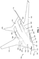
- FIG. 1-21 show an example of an aircraft 100 in a blended-wing-body configuration 110 having embedded engines 202.
- Figures 1-2 show perspective views of the blended-wing-body configuration 110.
- the aircraft 100 includes a centerbody 120 which has an airfoil-shaped cross section.
- the aircraft 100 includes a pair of wings 140 that are separated from each other by the centerbody 120.
- the blended-wing-body configuration 110 may be distinguished from a conventional tube-and-wing aircraft (not shown) in that each of the wings 140 of the blended-wing-body configuration 110 are integral with the centerbody 120 and smoothly blend into the centerbody 120.
- the centerbody 120 extends from a nose 122 to an aft portion 126 of the centerbody 120.
- the aircraft 100 may be constructed of metallic material (e.g., aluminum, titanium, etc.) and/or non-metallic material (e.g., fiber-reinforced polymer matrix material such as carbon-fiber composite material).
- the aircraft 100 has an aircraft centerline 102 which, in the present disclosure, is the longitudinal axis 106 of the aircraft 100.
- the aircraft 100 has an upper mold line 128, a lower mold line 130, and a pair of centerbody leading edge portions 132 respectively on opposite sides of the aircraft centerline 102.
- the upper mold line 128 of the centerbody 120 may be described as the outer mold line on the upper side of the centerbody 120
- the lower mold line 130 of the centerbody 120 may be described as the outer mold line on the lower side of the centerbody 120.
- the aircraft 100 includes a propulsion system 200 having at least one pair of engines 202 located on opposite sides of the aircraft centerline 102.
- the engines 202 are mounted within the centerbody 120 between the upper mold line 128 and the lower mold line 130.
- the engines 202 are embedded within the centerbody 120 of the aircraft 100 as shown in Figure 9 and described in greater detail below.
- the centerbody 120 includes a pair of air inlets 240 located respectively along the pair of centerbody leading edge portions 132 which may be described as the forward region of the airfoil of the centerbody 120.
- the air inlets 240 may be located below the leading edge forwardmost point 134 ( Figure 9 ) of the centerbody leading edge portions 132, or the air inlets 240 may be located above the leading edge forwardmost point 134 of the centerbody leading edge portions 132, depending upon the aircraft aerodynamics and other considerations.
- the air inlets 240 may be located below the leading edge forwardmost point 134 which may result in better aerodynamics for the air inlet 240 but which may allow more noise from the engine fan(s) 212 ( Figure 9 ) to radiate to the ground below.
- the air inlets 240 may be located above the leading edge forwardmost point 134 which may result in less noise from the engine fan(s) 212 radiating to the ground but presenting greater challenges for the aerodynamics of the air inlets 240.
- the pair of air inlets 240 are respectively fluidly coupled to the pair of engines 202.
- the centerbody 120 may include a pair of inlet ducts 244 respectively fluidly coupling the pair of air inlets 240 to the pair of engines 202.
- the centerbody 120 also includes a pair of exhaust outlets 260 located in the aft portion 126 of the centerbody 120.
- the pair of exhaust outlets 260 are respectively fluidly coupled to the pair of engines 202.
- the centerbody 120 may include a pair of exhaust ducts 264 respectively fluidly coupling the pair of exhaust outlets 260 to the pair of engines 202.
- the upper mold line 128 and the lower mold line 130 define the aerodynamic contour of the centerbody 120.
- the size and shape of the centerbody 120 may be such that the engines 202 are embedded within the centerbody 120 in a manner that avoids the need for locally-placed drag-reducing blisters or fairings (not shown) otherwise required for covering components or portions of the engines 202 that would protrude above the aerodynamic contour.
- the airfoil-shaped cross section of the centerbody 120 may be a shape that generates lift.
- the airfoil-shaped cross section of the centerbody 120 may generate lift during forward motion of the aircraft 100 by causing the oncoming airflow to pass over the upper mold line 128 of the centerbody 120 at a higher speed than the speed at which the oncoming airflow passes over the lower mold line 130 of the centerbody 120.
- the difference in the speed of the airflow may be due to a relatively higher degree of curvature of the upper mold line 128 of at least a portion of centerbody 120 than the degree of curvature of the lower mold line 130 of the same portion of the centerbody 120.
- the higher degree of curvature of the upper mold line 128 may result in an area of relatively low air pressure above the centerbody 120 and relatively high air pressure below the centerbody 120.
- the difference in air pressure above and below the centerbody 120 may result in a net upward lifting force generated by the centerbody 120.
- the combination of the net upward lifting force generated by the centerbody 120 and lift generated by the wings 140 may support the weight of the aircraft 100 during level flight.
- the aircraft 100 may reduce or eliminate the negative impact that externally-mounted engines (not shown) would have on the aerodynamics of the aircraft 100.
- embedding the engines 202 within the centerbody 120 may reduce or eliminate aerodynamic drag otherwise generated by externally-mounted engines.
- the reduction in aerodynamic drag may result in improved fuel efficiency.
- the fuel efficiency of a blended-wing-body configuration 110 aircraft 100 with embedded engines 202 may be up to 30 percent less than the fuel efficiency of a similarly sized tube-and-wing aircraft.
- the wings 140 extend upwardly from the centerbody 120 at a dihedral angle relative to horizontal.
- the aircraft 100 may include wings 140 that have no dihedral.
- the wings 140 may extend downwardly from the centerbody 120 at an anhedral angle relative to horizontal.
- each one of the vertical stabilizers 170 may be located at a position that avoids the afterwardly-directed exhaust stream (not shown) exiting the exhaust outlets 260 from directly impinging on the vertical stabilizers 170.
- each one of the vertical stabilizers 170 is canted at a non-vertical orientation which may advantageously provide improved controllability of the aircraft 100 relative to stabilizers (not shown) that are vertically oriented.
- vertical stabilizers 170 that are canted may be configured to provide or assist in pitch control and/or yaw control of the aircraft 100.
- the centerbody 120 may have a generally flat or slightly curved upper surface when the aircraft 100 is viewed along an aft-looking direction.
- the lower surface of the centerbody 120 may be generally flat or slightly curved in the center portion of the aircraft 100 near the aircraft centerline 102.
- the lower surface of the centerbody 120 may curve upwardly towards the lower side of the corresponding wing 140 and smoothly blend into the lower surface of the wing 140.
- At least a portion of the centerbody 120 may have a width that is larger than the overall height or thickness of the centerbody 120.
- the centerbody 120 may have a width that accommodates a payload bay 124 ( Figure 7 ) in addition to accommodating the inlet ducts 244 ( Figures 1-2 ), the engines 202, and the exhaust ducts 264 ( Figures 1-2 ).
- each one of the air inlets 240 may be generally aligned with the engine 202 to which the air inlet 240 is fluidly coupled.
- each air inlet 240 may at least partially overlap the cross-sectional area bounded by the engine duct 210 ( Figure 6 ) enclosing the engine 202.
- the alignment of each air inlet 240 with the corresponding engine 202 may facilitate airflow into the engine 202.
- each air inlet 240 may be described as having an inlet geometric center 246 which may be generally defined as the area centroid of an area bounded by a perimeter of the air inlet 240 at the outer mold line of the centerbody leading edge portion 132 when the air inlet 240 is viewed from a location forward of the aircraft 100 looking aft along a direction parallel to the aircraft centerline 102.
- each air inlet 240 may be located on the corresponding centerbody leading edge portion 132 such that the engine centerline 204 of the corresponding engine 202 extends through the inlet geometric center 246.
- the engine centerline 204 of each engine 202 may be generally aligned with the aircraft centerline 102 when the aircraft 100 is viewed from the top-down direction.
- the engine centerline 204 of each engine 202 may be canted or tilted relative to the aircraft centerline 102 and which may provide advantages for the flow path from the air inlets 240 to the engines 202, and/or advantages for the flow path from the engines 202 to the exhaust outlets 260.
- each air inlet 240 may be located on the corresponding centerbody leading edge portion 132 such that the inlet geometric center 246 of the air inlet 240 is offset by an air inlet offset 248 distance from the engine centerline 204 of the corresponding engine 202.
- the inlet geometric center 246 of each air inlet 240 may be located inboard of and below the engine centerline 204 of the corresponding engine 202.
- each air inlet 240 may be the result of the air inlet 240 being located below the leading edge forwardmost point 134 (e.g., see Figure 9 ) on the centerbody leading edge portion 132 as a means to reduce or avoid disruptions to the incoming airflow that may otherwise occur at high angles of attack if the majority of each air inlet 240 were located above the leading edge forwardmost point 134 on the centerbody leading edge portion 132, as mentioned above and described below.
- the inboard direction may be described as a horizontal direction toward the aircraft centerline 102 when the aircraft 100 is viewed along a top-down direction.
- the outboard direction may be described as a horizontal direction away from the aircraft centerline 102 when the aircraft 100 is viewed along a top-down direction.
- each air inlet 240 may have a non-circular inlet shape when the air inlet 240 is viewed along a direction parallel to the aircraft centerline 102.
- each air inlet 240 may have a generally rectangular or trapezoidal shape with rounded corners.
- Figure 3 illustrates each one of the air inlets 240 having an inlet width that is greater than an inlet height.
- each air inlet 240 may have a generally circular or oval shape that may be complementary to a generally circular shape of the engine duct 210 which may enclose the engine 202.
- Each air inlet 240 may be configured in any one of a variety of shapes other than the above-mentioned rectangular, trapezoidal, oval, or circular shapes.
- each exhaust outlet 260 may be defined in part by an exhaust duct cowling 270 that may protrude above the upper mold line 128 of the centerbody 120.
- each exhaust outlet 260 may be defined in part by an exhaust duct ramp 272 ( Figure 2 ) that may extend afterwardly from each one of the exhaust outlets 260.
- Each exhaust duct ramp 272 may be a depression in the upper mold line 128 at the aft end of the exhaust duct cowling 270.
- the aft end of each exhaust duct ramp 272 may smoothly blend into the upper mold line 128 of the aft portion 126 of the centerbody 120.
- each exhaust outlet 260 has an outlet geometric center 266. Similar to the above-described inlet geometric center 246 ( Figure 3 ) of each air inlet 240 ( Figure 3 ), the outlet geometric center 266 may be generally defined as the area centroid of an area bounded by a perimeter of the exhaust outlet 260 when viewed from a location aft of the aircraft 100 looking forward along a direction parallel to the aircraft centerline 102. The perimeter of the area of each exhaust outlet 260 may be defined in part by the exhaust duct cowling 270 of the exhaust outlet 260. The outlet geometric center 266 of each one of the exhaust outlets 260 may be offset from the engine centerline 204 of the corresponding engine 202 by an exhaust outlet offset 268 distance.
- the outlet geometric center 266 of each exhaust outlet 260 may be located vertically above the engine centerline 204, and which may be a result of the exhaust outlets 260 being located in the upper mold line 128 of the centerbody 120. As described in greater detail below, locating the exhaust outlets 260 in the upper mold line 128 may advantageously reduce airport noise that would otherwise occur if the exhaust outlets 260 were defined in the lower mold line 130 of the centerbody 120.
- the outlet geometric center 266 of each exhaust outlet 260 may also be located inboard of the engine centerline 204 of the corresponding engine 202.
- Locating each exhaust outlet 260 inboard of the corresponding engine centerline 204 may advantageously reduce asymmetric thrust as may occur in the event of one of the engines 202 becoming inoperable or producing less thrust than the other engine 202.
- positioning the exhaust outlets 260 such that the outlet geometric center 266 of each exhaust outlet 260 is inboard of the engine centerline 204 of the corresponding engine 202 may avoid direct impingement of the afterwardly-directed exhaust stream (not shown) onto the vertical stabilizers 170.
- each exhaust outlet 260 may have a generally rectangular shape with rounded inner corners when the exhaust outlets 260 are viewed along a forward-facing direction.
- each exhaust outlet 260 may have an outlet width that is greater than an outlet height.
- the exhaust outlets 260 may be provided in any one a variety of shapes.
- each exhaust outlet 260 may have the shape of a circle segment (not shown) which may result from each exhaust duct ramp 272 being generally planar and each exhaust duct cowling 270 having an arc-shaped cross section.
- each exhaust outlet 260 may have the shape of an oval, or each exhaust outlet 260 may have a flat upper surface and flat lower surface with semi-circular opposing ends coupling the flat upper and lower surface.
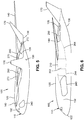
- FIG. 5 is a forward-looking perspective view of the blended-wing-body configuration 110 aircraft 100 showing the air inlets 240 located along the centerbody leading edge portion 132. Also shown are the exhaust outlets 260 defined in the upper mold line 128 of the aircraft 100. As mentioned above, each exhaust outlet 260 may include an exhaust duct cowling 270 which has a forward end and an aft end. In an example, the forward end of the exhaust duct cowling 270 may be tangent with the upper mold line 128 of the centerbody 120. The aftwardly-extending remaining portion of the exhaust duct cowling 270 may protrude above the upper mold line 128 of the centerbody 120.
- each exhaust outlet 260 may have an exhaust duct ramp 272, the forward end of which may be located below the upper mold line 128.
- the aft end of the exhaust duct ramp 272 may smoothly blend into the aerodynamic contour of the upper mold line 128 of the centerbody 120.
- the aft end of the exhaust duct ramp 272 may be tangent to the upper mold line 128.
- the exhaust duct cowling 270 and/or the exhaust duct ramp 272 may be formed of high-temperature material such as titanium alloy or other material capable of withstanding the high temperatures of the exhaust stream from the exhaust outlets 260.
- the location of the exhaust outlets 260 on the upper mold line 128 allows the centerbody 120 to provide partial blocking or shielding of exhaust noise such as when the aircraft 100 is on approach to an airport.
- embedding the engines 202 within the centerbody 120 may reduce airport community noise relative to the noise generated by exposed engines of a conventional tube-and-wing aircraft.
- the exhaust outlets 260 may be defined in the lower mold line 130 of the centerbody 120 instead of on the upper mold line 128. In a further example not shown, the exhaust outlets 260 may be split between the upper mold line 128 and the lower mold line 130 of the centerbody 120. In a still further example not shown, the exhaust outlets 260 may be defined on the centerbody trailing edge portion 136. For example, the exhaust duct of each one of the engines 202 may blend into an exhaust duct cowling 270 that protrudes above the upper mold line 128 and protrudes below the lower mold line 130, and which may terminate at the centerbody trailing edge portion 136.
- FIG 6 is a side view of the blended-wing-body configuration 110 aircraft 100 in an example in which each air inlet 240 is located along the centerbody leading edge portion 132 of the centerbody 120. Also shown is an exhaust outlet 260 defined in the upper mold line 128 of the centerbody 120.
- the aircraft 100 may include an inlet duct 244 fluidly coupling each air inlet 240 to a corresponding one of the engines 202.
- Each engine 202 may include an engine duct 210 ( Figure 9 ) which may surround the engine 202 and may function as the outer wall for a bypass stream 214 ( Figure 9 ) flowing through the engine 202, as described below.
- the aircraft 100 may additionally include an exhaust duct 264 fluidly coupling each engine 202 to a corresponding one of the exhaust outlets 260.
- Each exhaust duct 264 may be formed of a material (e.g., titanium alloy) capable of withstanding the high-temperature exhaust stream.
- Figure 7 is a top view of the blended-wing-body configuration 110 aircraft 100 showing the general configuration of the aircraft 100 having the pair of wings 140 extending outwardly from the centerbody 120.
- the centerbody 120 extends from the nose 122 to the aft portion 126.
- the aft portion 126 may include one or more tail surfaces such as the pair of vertical stabilizers 170 shown in Figures 1-7 .
- the aircraft 100 may include one or more tail surfaces arranged in any one of a variety of different configurations, and is not limited to a pair of vertical tails as shown in the figures.
- the aircraft 100 may include a single centrally-located vertical tail (e.g., on the aircraft centerline 102) for yaw control, and may optionally include a horizontal stabilizer and/or elevator mounted on the vertical tail for pitch control.
- a single centrally-located vertical tail e.g., on the aircraft centerline 102
- a horizontal stabilizer and/or elevator mounted on the vertical tail for pitch control.
- the aircraft 100 includes a payload bay 124 located between the pair of engines 202. Also shown are the wings 140 smoothly blended into the centerbody 120. In the example shown, the wings 140 are swept aftwardly. However, in other examples not shown, the wings 140 may be swept forwardly, the wings 140 may be non-swept, or the wings 140 may be forwardly and afterwardly pivotable for adjusting the sweep angle of the wings 140. As shown in Figure 7 , the aircraft 100 may lack a distinct structural line or joint between each wing 140 and the centerbody 120. In the present disclosure, the dividing line (e.g., an imaginary forward-aft-extending line) between each wing 140 and the centerbody 120 is described as the wing-centerbody juncture 148.
- the dividing line e.g., an imaginary forward-aft-extending line
- the location of the wing-centerbody juncture 148 may be defined in terms of the trailing edge sweep angle of the centerbody 120 and the wings 140.
- the centerbody 120 has a centerbody trailing edge portion 136 having a centerbody trailing edge sweep angle 138 which is defined relative to the transverse axis 108 of the aircraft 100.
- the transverse axis 108 is oriented perpendicular to the aircraft centerline 102.
- each one of the wings 140 has a wing leading edge portion 142 and a wing trailing edge portion 144.
- the wing trailing edge portion 144 has a wing trailing edge sweep angle 146 defined relative to the transverse axis 108.
- the wing trailing edge sweep angle 146 may be different than the centerbody trailing edge sweep angle 138.
- the intersection of the wing trailing edge portion 144 with the centerbody trailing edge portion 136 may be described as the trailing edge planform break 147.
- the intersection of the wing leading edge portion 142 with the centerbody leading edge portion 132 may be described as the leading edge planform break 143.
- the leading edge planform break 143 is aligned with the trailing edge planform break 147.
- the blended-wing-body configuration 110 may be configured such that the leading edge planform break 143 is located further inboard or further outboard than the trailing edge planform break 147.
- the wing-centerbody juncture 148 may be located inboard of the trailing edge planform break 147.
- the wing-centerbody juncture 148 may be located inboard of the trailing edge planform break 147 and slightly outboard of the exhaust outlet 260.
- the wing-centerbody juncture 148 may be located at the leading edge planform break 143, or outboard of the leading edge planform break 143.
- the wing-centerbody juncture 148 on each side of the aircraft 100 may be located at the leading edge planform break 143.
- the wing-centerbody juncture 148 may be located inboard or outboard of the leading edge planform break 143.
- the location of the wing-centerbody juncture 148 on each side of the aircraft 100 may be defined in terms of the airfoil thickness-to-chord ratio of the wings 140 relative to the airfoil thickness-to-chord ratio of the centerbody 120.
- the centerbody 120 of the aircraft 100 may include a payload bay 124.
- the aircraft 100 may be configured for use as a subsonic commercial or military freighter for carrying cargo in the payload bay 124.
- the shape of the centerbody 120 allows for a large payload bay 124.
- the relatively wide shape of the centerbody 120 allows for a relatively wide payload bay 124 capable of carrying cargo having a larger width than the cargo that may be carried in the fuselage of a tube-and-wing aircraft.
- the aircraft 100 may be configured as a tanker aircraft providing refueling support in a military or commercial application.
- the payload bay 124 may be configurable as a passenger cabin (not shown) having seats for carrying passengers.
- the nose 122 of the aircraft 100 is shown having a cockpit for a flight crew for piloting the aircraft 100, the aircraft 100 may optionally be configured and/or operated as an unmanned aerial vehicle (UAV) which may be remotely controlled. Regardless of whether the aircraft 100 is unmanned or piloted by a flight crew, the aircraft 100 may be configured for use in a variety of civilian, commercial, governmental, and/or military applications.
- UAV unmanned aerial vehicle
- each inlet duct 244 may be generally aligned with the engine centerline 204 of the corresponding engine 202 to reduce or avoid the disruption of airflow into the engine 202.
- Each exhaust duct 264 may have a slight S-shaped configuration when the aircraft 100 is viewed from a top-down direction. The S-shaped configuration may allow the exhaust from each engine 202 to smoothly flow to the exhaust outlet 260 which may be located inboard of the engine centerline 204 of the corresponding engine 202. As mentioned above, positioning each exhaust outlet 260 at a location that is inboard of the corresponding engine centerline 204 may reduce asymmetric thrust that may occur if one engine 202 becomes inoperable.
- Figure 8 is a sectional view of the centerbody 120 of the blended-wing-body configuration 110 aircraft 100 of Figure 7 taken along the aircraft centerline 102.
- the centerbody 120 has an airfoil-shaped cross section at the aircraft centerline 102.
- the upper mold line 128 of the centerbody 120 may have a relatively higher degree of curvature than the lower mold line 130 and which may result in the generation of lift.
- FIG. 9 shown is a sectional view of the blended-wing-body configuration 110 aircraft 100 taken along an engine centerline 204 and showing an engine 202 mounted within the centerbody 120 between the upper mold line 128 and the lower mold line 130.
- Each engine 202 may be enclosed within an engine duct 210 that is internal to the centerbody 120.
- an inlet duct 244 fluidly coupling the air inlet 240 to the engine 202
- an exhaust duct 264 fluidly coupling the engine 202 to an exhaust outlet 260.
- each engine 202 may be configured as a turbofan engine having at least one fan 212 and a core 216.
- the fan 212 may be rotatably driven by the core 216 for forcing the bypass stream 214 of air through an annular passage between the engine duct 210 and the core 216.
- the core 216 has one or more turbines 224, 226 and one or more compressors 220, 222.
- the core 216 may include a low-pressure compressor 220, a high-pressure compressor 222, a low-pressure turbine 224, and a high-pressure turbine 226.
- Each one of the compressors 220, 222 and turbines 224, 226 are rotor discs having multiple blades rotating at relatively high speeds.
- the rotating compressors 220, 222 and turbines 224, 226 draw a core stream 218 through the core 216.
- the combination of the bypass stream 214 and the efflux or exhaust of the core stream 218 results in thrust that propels the aircraft 100.
- the engines 202 may each have a bypass ratio of greater than 5.
- each one of the engines 202 may have a bypass ratio in the range of from about 5-20.
- each one of the engines 202 may have a bypass ratio of less than 5, or a bypass ratio higher than 20.
- the bypass ratio may be described as the ratio of the mass flow rate of the bypass stream 214 to the mass flow rate of the core stream 218.
- the engines 202 are not limited to being configured as turbine engines embedded within the centerbody 120, but may include alternative engine configurations.
- one or more of the engines 202 of the aircraft 100 may be configured as a gas generator (not shown) embedded within the centerbody 120 and configured to generate electricity for hybrid electric propulsion.
- the aircraft 100 has an aircraft center of gravity 104.
- Each one of the engines 202 has an engine center of gravity 208 which may be longitudinally positioned (i.e., along a direction parallel to the aircraft centerline 102 - Figure 8 ) within an engine center of gravity offset 209.
- the engine center of gravity 208 may be longitudinally positioned within a distance from the aircraft center of gravity 104 of 20 percent (i.e., between 80-120 percent) of a horizontal distance from the nose forwardmost point of the nose 122 ( Figure 8 ) to the aircraft center of gravity 104.
- the horizontal distance may be measured along the aircraft centerline 102 and may extend between the aircraft center of gravity 104 and an imaginary vertical plane (e.g., a reference datum - not shown) oriented perpendicular to the aircraft centerline 102 and located on the outer mold line of the nose 122.
- the aircraft center of gravity 104 is the empty weight center of gravity and is based on the empty weight of the aircraft 100 which may be described as the weight of the aircraft 100 without fuel, cargo, or passengers in the aircraft 100.
- the engine center of gravity 208 may be longitudinally positioned at any location relative to the aircraft center of gravity 104, and is not limited to the above-described arrangement.
- the internal location of the engines 202 within the centerbody 120 locates the thrust line of each engine 202 vertically near the aircraft center of gravity 104.
- the internal location of the engines 202 within the centerbody 120 of the aircraft 100 provides the opportunity to optimize the longitudinal location of the engine center of gravity 208.
- the location of each engine center of gravity 208 longitudinally near the aircraft center of gravity 104 may enhance the flight characteristics of the aircraft.
- the above-described and illustrated location of the engines 202 may reduce the thrust pitching moment induced by the engines 202 relative to a large thrust pitching moment induced by externally-mounted engines (not shown).
- the internal location of the engines 202 within the centerbody 120 of the presently-disclosed aircraft 100 may reduce the length and complexity of the primary load-carrying structure (not shown) supporting the engines 202 within the centerbody 120, relative to longer and more complex load-carrying structure that may be required to support externally-mounted engines (not shown) such as on pylons protruding upwardly from an aft end of an aircraft.
- the reduced length and complexity of the engine-supporting structure may result in a reduction in aircraft weight relative to a similar aircraft having externally mounted engines.
- the internal location of the engines 202 within the centerbody 120 may allow for improved accessibility to the engines 202 (e.g., for engine maintenance and/or removal) relative to more difficult accessibility for externally-mounted engine supported on upwardly-extending pylons (not shown). Even further, the internal location of the engines 202 within the centerbody 120 may reduce exposure of the engines 202 to environmental effects or damage from external objects. For example, the internal location of the engines 202 within the centerbody 120 may eliminate the potential for contact of the engines 202 with objects and/or vehicles at an airport.
- the internal location of the engines 202 within the centerbody 120 may result in the aircraft 100 generating less noise during take-off and landing which may allow the aircraft 100 to be operated earlier and later in the day, and possibly during airport curfew hours.
- the internal location of the engines 202 on opposite sides of the centerbody 120 may improve survivability of each engine 202 in the event of an uncontained engine failure (e.g., rotor blade departure) of one of the engines 202.
- each air inlet 240 may be located at least partially below a leading edge forwardmost point 134 of the corresponding centerbody leading edge portion 132 and which results in the inlet geometric center 246 ( Figure 3 ) of each air inlet 240 being located below the engine centerline 204 of the corresponding engine 202.
- locating each air inlet 240 below the leading edge forwardmost point 134 on the centerbody leading edge portion 132 avoids disrupting the aerodynamics of the oncoming airflow passing over the wings 140.
- each air inlet 240 below the leading edge forwardmost point 134 on the corresponding centerbody leading edge portion 132 may avoid the potential blanketing of airflow into the air inlets 240 that may occur at high angles of attack if the air inlets 240 were located above the leading edge forwardmost point 134 of the centerbody leading edge portions 132.
- each air inlet 240 air may be located on the corresponding centerbody leading edge portion 132 such that the inlet geometric center 246 is vertically centered on the leading edge forwardmost point 134 such that a portion (e.g., approximately half) of the inlet cross-sectional area is located above the leading edge forwardmost point 134 and the remaining portion of the inlet cross-sectional area is located below the leading edge forwardmost point 134 of the air inlet 240.
- the location of the wing-centerbody juncture 148 ( Figure 7 ) on each side of the aircraft 100 may be defined in terms of the airfoil thickness-to-chord ratio of the wings 140 ( Figure 10 ) and centerbody 120 ( Figure 9 ).
- Figure 9 shows a cross section of the centerbody 120 of the aircraft 100 at the location of the engine centerline 204.
- Figure 10 shows a cross section of a wing 140 of the aircraft 100 ( Figure 9 ).
- the airfoil thickness-to-chord ratio represents the ratio of the airfoil thickness to the airfoil chord.
- the airfoil chord of an airfoil may be described as the distance from the leading edge of the airfoil to the trailing edge of the airfoil.
- the airfoil thickness may be described as the maximum thickness of the airfoil along the airfoil chord.
- the centerbody 120 may have an airfoil thickness-to-chord ratio of at least 10 percent, and each wing 140 may have an airfoil thickness-to-chord ratio of less than 10 percent.
- the wing-centerbody juncture 148 on each side of the aircraft 100 may be defined as the location where the airfoil thickness-to-chord ratio changes from less than 10 percent to at least 10 percent.
- Figure 11 is a top view of an example of a blended-wing-body configuration 110 aircraft 100 in which the propulsion system 200 includes two (2) pairs of engines 202 located on laterally opposite sides of the aircraft centerline 102.
- the lateral direction may be described as a direction in the horizontal plane and oriented parallel to the transverse axis 108 ( Figure 7 ) of the aircraft 100.
- the longitudinal direction may be described as a forward-aft direction oriented parallel to the aircraft centerline 102.
- the adjacent pair of engines 202 on each side of the aircraft centerline 102 may be longitudinally staggered or offset from each other.
- Longitudinally offsetting the adjacent engines 202 may prevent an uncontained engine failure (e.g., due to rotor blade departure from one of the compressors 220, 222 and/or turbines 224, 226 - Figure 9 ) of one engine 202 from affecting the operability of the adjacent engine 202.
- the increased redundancy provided by two (2) pairs of engines 202 on each side of the aircraft 100 may enhance the reliability of the aircraft 100 propulsion system 200.
- the engines 202 may be provided in any one of the above-describe configurations including, but not limited to, turbine engines.
- one or more pairs of the engines 202 embedded within the centerbody 120 may be configured as the above-described turbofan engine shown in Figure 9 , and may be of any suitable bypass ratio.
- one or more of the engines 202 embedded within the centerbody 120 on each side of the aircraft centerline 102 may be provided as a gas generator (not shown) for generating electricity for a hybrid engine (not shown) for electric propulsion.
- an aircraft 100 having two (2) pairs of engines 202 on each side of the aircraft centerline 102 as shown in Figure 11 , one of the engines 202 on each side of the aircraft 100 may be a turbine engine and the adjacent engine 202 may be a gas generator for hybrid electric propulsion.
- an aircraft 100 may have three (3) pairs of engines 202 embedded within the centerbody 120 on each side of the aircraft centerline 102.
- two (2) of the three (3) engines 202 on each side of the aircraft centerline 102 may be turbine engines, and the third of the three (3) engines 202 may be a gas generator (not shown) for a hybrid engine.
- the aircraft 100 may be configured to include any number of engines 202 embedded within the centerbody 120, and is not limited to the above-described and/or illustrated examples.
- the propulsion system 200 may be configured such that each engine 202 may have a dedicated inlet duct 244 fluidly coupling an air inlet 240 to the engine 202, and a dedicated exhaust duct 264 fluidly coupling the engine 202 to an exhaust outlet 260.
- an aircraft 100 may be provided with a propulsion system 200 in which one or more of the engines 202 share at least a portion of an inlet duct 244 and/or at least a portion of an air inlet 240 with at least one other engine 202 of the propulsion system 200.
- the propulsion system 200 may be configured such that one or more of the engines 202 share at least a portion of an exhaust duct 264 and/or at least a portion of an exhaust outlet 260 with at least one other engine 202 of the propulsion system 200.
- the centerbody leading edge portion 132 on each side of the aircraft centerline 102 may have a single air inlet 240 (not shown).
- Each one of the engines 202 on each side of the aircraft centerline 102 may have a dedicated inlet duct 244 that may be coupled to the single air inlet 240.
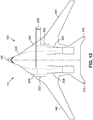
- Figure 12 is a top view of an example of a blended-wing-body configuration 110 aircraft 100 having a pair of engines 202 that are longitudinally staggered or offset from each other.
- the engines 202 are located on laterally opposite sides of the aircraft centerline 102. If configured as turbofan engines, the engines 202 may be longitudinally offset by an engine offset 206 distance that may prevent an uncontained failure of the fan(s) 212 ( Figure 9 ), the compressor(s) 220, 222 ( Figure 9 ), and/or the turbines(s) to 24, 226 ( Figure 9 ) of one engine 202 from affecting the operability of the other engine 202.
- the engines 202 may be longitudinally offset by an engine offset 206 distance such that the turbines 224, 226 of the engine 202 on one side of the aircraft centerline 102 are longitudinally forward of the fan 212 of the engine 202 on the opposite side of the aircraft centerline 102.
- the aircraft 100 may include a pair of the vertical stabilizers 170 located on opposite sides of the aircraft centerline 102.
- the vertical stabilizers 170 may be canted (i.e., non-vertically oriented as shown) or the vertical stabilizers 170 may be vertically oriented (not shown).
- Each one of the vertical stabilizers 170 has a stabilizer leading edge 172.
- the pair of exhaust outlets 260 may be located at a position that is longitudinally aft of the vertical stabilizers 170.
- the aft end of the exhaust ducts 264 may be located aft of the stabilizer leading edges 172.
- the aft end of the exhaust ducts 264 may be located aft of the strake leading edges 176.
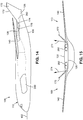
- Figure 15 is a forward-looking end view of the aircraft 100 showing the vertical stabilizers 170 and/or the strakes 174 ( Figures 14-15 ) acoustically blocking at least a portion of the exhaust noise emanating from the exhaust outlets 260.
- the exhaust noise is partially represented by the acoustic emission vectors 274 which are shown extending laterally (e.g., sideway) from the exhaust outlets 260.
- exhaust noise may emanate from the exhaust outlets 260 generally omnidirectionally except for in the downward direction due to at least partial blocking of some of the exhaust noise by the upper surface of the centerbody 120.
- the acoustic emission vectors 274 that are shown may reflect off of the vertical stabilizers 170 and/or the strakes 174 and may be deflected in a generally upward direction, depending upon the orientation of the vertical stabilizers 170.
- the generally upward deflection of the exhaust noise may reduce the amount of airport community noise generated by the aircraft 100, thereby potentially allowing the aircraft 100 to operate during airport curfew hours such as during the early morning hours and/or late at night.
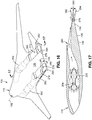
- Figures 16-17 illustrate an example of a blended-wing-body configuration 110 aircraft having a pair of thrust-vectoring flaps 276 (e.g., blown flaps) for varying or steering the direction of the exhaust streams (e.g., engine thrust) discharged from the engines 202.
- Figure 16 is a top-down view of the aircraft.
- Figure 17 is a sectional view through the engine centerline 204 and illustrating one of the thrust-vectoring flaps 276.
- the pair of thrust-vectoring flaps 276 are mounted proximate the centerbody trailing edge portion 136 and are located downstream respectively of the pair of exhaust outlets 260. In this regard, the thrust-vectoring flaps 276 are located downstream of the exhaust duct ramps 272.
- each one of the thrust-vectoring flaps 276 terminates at a location coincident with the aftermost edge of the centerbody trailing edge portion 136.
- the aftermost edge of the thrust-vectoring flaps 276 may terminate at a location that is forward of or aft of the aftermost edge of the centerbody trailing edge portion 136.
- the thrust-vectoring flaps 276 are pivotable in order to vary the direction of the exhaust streams that are respectively discharged by the pair of engines 202.
- the thrust-vectoring flaps 276 may be independently pivotable and may be actuated in coordination with each other.
- the thrust-vectoring flaps 276 are pivotable from a neutral position 280 to an upward position 282 and/or to a downward position 284. In the neutral position 280, the aftermost edge of the thrust-vectoring flaps 276 may be aligned with or coincident with the aftermost edge of the centerbody trailing edge portion 136.
- Each one of the thrust-vectoring flaps 276 may be pivotable about a pivot axis (not shown) oriented perpendicular to the aircraft centerline 102 ( Figure 16 ).
- the thrust-vectoring flaps 276 may be pivotable about the pivot axis from the neutral position 280 to an upward position 282 of up to +45 degrees or more, and/or from the neutral position 280 to a downward position 284 of up to - 45 degrees or more.
- the thrust-vectoring flaps 276 When the thrust-vectoring flaps 276 are pivoted into an upward position 282, the exhaust streams from the engine 202 impinge on the thrust-vectoring flaps 276 which may generate a downward force on the aft portion 126 of the centerbody 120, causing the nose of the aircraft 100 to pitch upwardly.
- the thrust-vectoring flaps 276 When the thrust-vectoring flaps 276 are pivoted into a downward position 284, at least a portion of the exhaust streams from each engine 202 may tend to follow the downwardly deflected surfaces of the thrust-vectoring flaps 276 due to the Coanda effect, and which may also result in an area of low pressure above the thrust-vectoring flaps 276 and an area of higher pressure below the thrust-vectoring flaps 276 (due to the airstream flowing along the lower mold line 130), the result of which may urge the aft portion 126 of the centerbody 120 upwardly causing the nose of the aircraft 100 to pitch downwardly. In this manner, the thrust-vectoring flaps 276 may increase the pitch controllability and/or maneuverability of the aircraft 100.
- FIG. 18 shown is an example of blended-wing-body configuration 110 aircraft in which the pair of exhaust outlets 260 include a pair of thrust-vectoring exhaust nozzles 278 for steering the direction of the exhaust streams from the engines 202 ( Figure 17 ).
- Figure 18 is a top-down perspective view of the aircraft 100 and
- Figure 19 is a bottom-up perspective view of the aircraft 100 showing the pair of thrust-vectoring exhaust nozzles 278 located proximate the centerbody trailing edge portion 136.
- the aftermost edge of the thrust-vectoring exhaust nozzles 278 may terminate at the same location as the aftermost edge of the centerbody trailing edge portion 136, similar to the above-described arrangement of the thrust-vectoring flaps 276 ( Figures 16-17 ).
- the thrust-vectoring exhaust nozzles 278 may be mounted such that the aftermost edge of the thrust-vectoring exhaust nozzles 278 is located forward of the aftermost edge of the centerbody trailing edge portion 136, or the aftermost edge of the thrust-vectoring exhaust nozzles 278 may be located aft of the aftermost edge of the centerbody trailing edge portion 136.
- the thrust-vectoring exhaust nozzles 278 may be provided in any one a variety of cross-sectional shapes including, but not limited to, an oval shape or a circular shape.
- Figure 20 is an end view of the aircraft 100 showing the thrust-vectoring exhaust nozzles 278 in the neutral position 280.
- Figure 21 is a sectional view of the aircraft 100 also showing the thrust-vectoring exhaust nozzles 278 in the neutral position 280.
- Also shown in Figure 21 is an example of a nose landing gear 123 in the extended position.
- the main landing gear 125 as shown in the extended position and also shown retracted within the centerbody 120. In the retracted position, the main landing gear 125 may be positioned within the centerbody 120 without protruding beyond the upper mold line 128 and/or the lower mold line 130 of the centerbody 120.
- the thrust-vectoring exhaust nozzles 278 are pivotable in coordination with each other for varying the direction of the exhaust streams for increasing the pitch controllability of the aircraft 100, similar to the above-described arrangement of the thrust-vectoring flaps 276.
- Each one of the thrust-vectoring exhaust nozzles 278 is vertically pivotable from the neutral position 280 to an upward position 282 and/or to a downward position 284.
- Each thrust-vectoring exhaust nozzle 278 may be pivotable about a pivot axis (not shown) oriented perpendicular to the forward-aft direction of the aircraft 100.
- the thrust-vectoring exhaust nozzles 278 may be pivoted from the neutral position 280 to an upward position 282 of up to +45 degrees or more, and/or from the neutral position 280 to the downward position 284 above to -45 degrees or more.
- each one of the thrust-vectoring exhaust nozzles 278 may be a unitary structure that pivots up and down about a pivot axis as mentioned above.
- each one of the thrust-vectoring exhaust nozzles 278 may include upper and lower nozzle surfaces that pivot up and downwardly independently on their own hinges, but in coordination with each other for steering the exhaust stream.
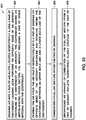
- Figure 22 is a flowchart of operations included in a method 300 of operating an aircraft 100 having a blended-wing-body configuration 110.
- Step 302 of the method 300 includes drawing air into at least one pair of air inlets 240 located respectively along a pair of centerbody leading edge portions 132 respectively on opposite sides of the aircraft centerline 102 of the centerbody 120 of the aircraft 100.
- the centerbody 120 has an airfoil-shaped cross section.
- the aircraft 100 includes a pair of wings 140 that are integral with the centerbody 120.
- step 302 of drawing the air into the pair of air inlets 240 may include drawing the air into the pair of air inlets 240 located at least partially below a leading edge forwardmost point 134 respectively of the pair of centerbody leading edge portions 132.
- Figure 9 illustrates the entirety of an air inlet 240 located below the leading edge forwardmost point 134 on the centerbody leading edge portion 132.
- locating the air inlet 240 below the leading edge forwardmost point 134 on the centerbody leading edge portion 132 instead of above the leading edge forwardmost point 134 may avoid the leading edge forwardmost point 134 of the leading edge blanketing the air inlets 240 when the aircraft 100 is at high angles of attack.
- Step 304 of the method 300 includes passing the air from the air inlets 240 into at least one pair of engines 202 respectively located on opposite sides of the aircraft centerline 102.
- Figures 1-7 illustrate an example of an aircraft 100 having a pair of engines 202
- the aircraft 100 may be provided in an example having any number of engines 202 embedded within the centerbody 120.
- the above-described example in Figure 11 shows an aircraft 100 having two (2) pairs of engines 202 respectively located on opposite sides of the aircraft centerline 102.
- each air inlet 240 may be generally aligned with the corresponding engine 202 which may facilitate airflow from the air inlet 240 into the engine 202.
- Each engine 202 is mounted within the centerbody 120 between an upper mold line 128 and a lower mold line 130 of the centerbody 120.
- the upper mold line 128 and the lower mold line 130 define the aerodynamic contour of the centerbody 120 which has an airfoil-shaped cross section capable of generating aerodynamic lift, as described above.
- step 304 of passing the air into the pair of engines 202 may comprise passing the air into the pair of engines 202 each having an engine center of gravity 208 located within a distance from the aircraft center of gravity 104 of 20 percent of a distance from the nose forwardmost point of the nose 122 to the aircraft center of gravity 104.
- the distance between the nose 122 and the aircraft center of gravity 104 may be measured along the aircraft centerline 102.
- the aircraft center of gravity 104 may be the empty weight center of gravity without fuel, cargo, or passengers in the aircraft 100.
- Step 306 of the method 300 includes combusting a fuel-air mixture within the pair of engines 202.
- each engine 202 may be a turbofan engine having a combustor (not shown) through which compressed air from the compressors 220, 222 is passed. Fuel may be injected into the compressed air and the fuel-air mixture may be ignited creating high-pressure exhaust which passes through turbines 224, 226 causing rotation of the turbines 224, 226 and the fan 212 at the front of each engine 202.
- step 306 of combusting the fuel-air mixture within the pair of engines 202 may comprise combusting the fuel-air mixture within a pair of turbine engines each having a bypass ratio of from about 5-20.
- the aircraft 100 may be provided with engines 202 having a bypass ratio higher than 20 or the engines 202 may have a bypass ratio lower than 5.
- Step 308 of the method 300 includes discharging an exhaust of the combustion of the fuel-air mixture from at least one pair of exhaust outlets 260 respectively fluidly coupled to the pair of engines 202.
- the discharge of the exhaust from the exhaust outlets 260 generates thrust for propelling the aircraft 100.
- step 308 of discharging the exhaust from the pair of exhaust outlets 260 may comprise discharging the exhaust from a pair of exhaust outlets 260 defined in the upper mold line 128 (e.g., the upper side) of the aft portion 126 of the centerbody 120 as shown in the figures.
- step 308 may comprise discharging the exhaust from exhaust outlets 260 defined in the lower mold line 130.
- step 308 may comprise discharging the exhaust from exhaust outlets 260 that are split between the upper mold line 128 and the lower mold line 130, or discharging the exhaust from exhaust outlets 260 located on the trailing edge portion of the aft portion 126 of the centerbody 120.
- the method may include discharging the exhaust from exhaust duct cowlings 270 corresponding to the one or more engines 202 of the aircraft 100.
- the exhaust exiting each exhaust outlet 260 may pass over an exhaust duct ramp 272 that may be formed of high-temperature material and which may be incorporated into the upper mold line 128 and/or the lower mold line 130.
- step 308 of discharging the exhaust from the pair of exhaust outlets 260 may comprise discharging the exhaust from the pair of exhaust outlets 260 each located inboard of the engine centerline 204 respectively of the pair of engines 202, as shown in Figure 4 .
- each exhaust outlet 260 may be offset in an inboard direction toward the aircraft centerline 102.
- locating each exhaust outlet 260 near the aircraft centerline i.e., when viewed from a top-down direction
- offsetting each exhaust outlet 260 in and inboard direction may avoid direct impingement of the exhaust stream against the vertical stabilizers 170.
- step 308 of discharging the exhaust from the pair of exhaust outlets 260 may comprise discharging the exhaust from a pair of thrust-vectoring flaps 276 mounted proximate the centerbody trailing edge portion 136 and located downstream respectively of the pair of exhaust outlets 260.
- the method may further include pivoting the thrust-vectoring flaps 276 (e.g., in coordination with each other) for varying a direction of the exhaust stream.
- the method may include pivoting the thrust-vectoring flaps 276 between the neutral position 280 and the upward position 282 and/or between the neutral position 280 and the downward position 284.
- the pivoting of the thrust-vectoring flaps 276 may enhance the pitch controllability of the aircraft 100 which may improve aircraft 100 maneuverability.
- step 308 of discharging the exhaust from the pair of exhaust outlets 260 may include discharging the exhaust from a pair of thrust-vectoring exhaust nozzles 278 ( Figures 18-21 ) located proximate the centerbody trailing edge portion 136.
- the method may include pivoting the thrust-vectoring exhaust nozzles 278 in coordination with each other for varying the direction of the exhaust stream from the aircraft 100.
- the thrust-vectoring exhaust nozzles 278 may be vertically pivoted from the neutral position 280 to the upper position and/or from the neutral position 280 to the downward position 284 for increasing pitch controllability of the aircraft 100.
- Step 308 of discharging the exhaust may include acoustically blocking, using the pair of vertical stabilizers 170 located on opposite sides of the aft portion 126, at least a portion of exhaust noise emanating from the pair of exhaust outlets 260.
- the side view of the aircraft 100 in Figure 14 shows the aft end of the exhaust duct cowlings 270 located at a position that is longitudinally aft of the stabilizer leading edges 172.
- the location of the exhaust duct cowlings 270 aft of the stabilizer leading edges 172 may allow the vertical stabilizers 170 to acoustically blocking at least a portion of the exhaust noise emanating from the exhaust outlets 260.
- Figure 15 shows an acoustic emission vector oriented in a laterally outboard direction from the outlet geometric center 266 of each exhaust outlet 260.
- the acoustic emission vector 274 represents a portion of the exhaust noise that may emanate from the exhaust outlet 260.
- the vertical stabilizers 170 may deflect the acoustic emission vectors 274 into an upward direction and away from the ground, which may have the effect of reducing the magnitude of airport community noise otherwise generated by the aircraft 100.
- the aircraft 100 may include a strake 174 ( Figures 13-14 ) extending forwardly from each of the vertical stabilizers 170. Each strake 174 may increase the blocking or shielding of exhaust noise emanating from the exhaust outlets 260.
- the aircraft 100 includes a pair of wings 140 integral with each other.
- the pair of wings 140 may be structurally joined to each other.
- the aircraft 100 may lack a distinct structural joint coupling the pair of wings 140.
- the dividing line between the pair of wings 140 may be described as the wing-wing juncture 150.
- Each one of the wings 140 has an upper mold line 128, a lower mold line 130, a wing leading edge portion 142 and a wing trailing edge portion 144.
- the wing leading edge portions 142 of the pair of wings 140 may converge at the nose 122 of the aircraft 100.
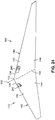
- Figure 23 is a top-down view of the aircraft 100 showing the pair of wings 140 integral with each other and within which at least one pair of engines 202 are embedded.
- the pair of wings 140 are non-separated by any intervening structure such as a fuselage (not shown), a centerbody, and/or other structures.
- the pair of wings 140 may be joined to each other at the wing roots (not shown) of the pair of wings 140.
- Each one of the wings 140 may have a generally constant airfoil shape from the wing root to the wing tip.
- the constant airfoil shape of each wing 140 may taper in size from the wing root to the wing tip.
- a flying wing configuration 112 may include a canopy or a cockpit that may be mounted at one or more locations along the wing-wing juncture 150.
- a flying wing configuration 112 may include an empennage (not shown) extending aftwardly from the wing trailing edge portions 144 of the pair of wings 140.
- one or more tail booms may extend aftwardly from the wings 140.
- An empennage may support one or more tail surfaces such as a horizontal tail and/or one or more vertical tails which may be vertically oriented or non-vertically oriented (e.g., canted).
- the flying wing configuration 112 may include one or more vertical tails (not shown) such as vertical fins mounted on the wings 140.
- any one of the aircraft configurations disclosed herein may include any one or more of a variety of other flight control surfaces (not shown) for directional control of the aircraft 100.
- any one of the aircraft configurations disclosed herein may include elevons, ailerons, flaps, spoilers, speed brakes, and/or one or more high-lift devices on the wing leading edge portion 142, such as leading edge slats, Krueger flaps, or other high-lift devices.
- any one of the aircraft configurations disclosed herein may include winglets (single winglets or split winglets - not shown) on the wing tips.
- any one of the components e.g., air inlets 240, inlet ducts 244, engines 202, exhaust ducts 264, exhaust outlets 260, etc.
- the above-described size, shape, configuration, and/or arrangement of any one of the components may be implemented on the flying wing configuration 112.
- the aircraft 100 has at least one pair of engines 202 located on opposite sides of the aircraft centerline 102 and mounted respectively within the pair of wings 140 between the upper mold line 128 and the lower mold line 130.
- Each engine 202 is configured as a turbofan engine which has at least one fan 212 and a core 216 as shown in Figure 29 and described in greater detail below.
- the engines 202 of the flying wing configuration 112 may not protrude beyond the upper mold line 128 or beyond the lower mold line 130 of the wings 140.
- the flying wing configuration 112 aircraft 100 includes a pair of air inlets 240 located respectively along the wing leading edge portions 142.
- the pair of air inlets 240 are respectively fluidly coupled to the pair of engines 202.
- a pair of inlet ducts 244 may respectively fluidly couple the pair of air inlets 240 to the pair of engines 202 in a manner similar to the above-described inlet ducts 244 of the blended-wing-body configuration 110 ( Figures 1-21 ).
- the air inlets 240 may not protrude beyond the upper mold line 128 or beyond the lower mold line 130 of the wing leading edge portion 142.
- the air inlets 240 may not protrude beyond the airfoil-shaped cross-section of the wing 140.
- the air inlets 240 of the flying wing configuration 112 (e.g., Figures 23-30 ) may be configured and positioned on the wing leading edge portions 142 of the wings 140 in a manner similar to the configuration and positioning of the air inlets 240 on the centerbody leading edge portions 132 of the blended-wing-body configuration 110 (e.g., Figures 1-21 ).
- each air inlet 240 may be located at least partially below a leading edge forwardmost point 134 of the wing leading edge portion 142 in a manner similar to the above-described positioning of the air inlets 240 along the centerbody leading edge portions 132 of the blended-wing-body configuration 110.
- an entirety of each air inlet 240 may be located below the leading edge forwardmost point 134 of the wing leading edge portion 142 which may avoid the blanketing of airflow into the air inlets 240 that may otherwise occur at high angles of attack for air inlets 240 located above the leading edge forwardmost point 134 of the wing leading edge portions 142.
- each air inlet 240 may be located on the corresponding wing leading edge portion 142 such that the inlet geometric center 246 ( Figure 25 ) is offset by an air inlet offset 248 ( Figure 25 ) distance from the engine centerline 204.
- the inlet geometric center 246 of each air inlet 240 may be located inboard of and below the engine centerline 204 similar to the above-described arrangement shown in Figure 3 .
- the aircraft 100 also includes a pair of exhaust outlets 260 respectively fluidly coupled to the pair of engines 202.
- a pair of exhaust ducts 264 ( Figure 23 ) may respectively fluidly couple the pair of exhaust outlets 260 to the pair of engines 202.
- the pair of exhaust outlets 260 may be defined in the upper mold line 128 respectively of the pair of wings 140 in a manner similar to the above-described location of the exhaust outlets 260 in the upper mold line 128 of the centerbody 120 of the blended-wing-body configuration 110.
- each one of the exhaust outlets 260 may be defined in part by an exhaust duct cowling 270 that may protrude above the upper mold line 128 of a respective wing 140.
- each exhaust outlet 260 may be defined in part by an exhaust duct ramp 272 ( Figure 23 ) that may extend afterwardly from the exhaust outlet 260.
- the exhaust duct ramp 272 may be configured as a depression in the upper mold line 128 of the wing 140.
- each exhaust outlet 260 may be offset by an exhaust outlet offset 268 distance.
- the outlet geometric center 266 may be located inboard of the engine centerline 204 of the corresponding engine 202 in an arrangement similar to the above-described positioning of the exhaust outlets 260 for the blended-wing-body configuration 110.
- Figure 27 is a top view of the aircraft 100 showing a slight S-shaped configuration of each exhaust duct 264 to allow the exhaust from each engine 202 to smoothly flow to the exhaust outlet 260.
- locating each exhaust outlet 260 inboard of the corresponding engine centerline 204 may advantageously reduce asymmetric thrust as may occur in the event of one of the engines 202 becoming inoperable.
- a payload bay 124 that may be included in the flying wing configuration 112.
- the exhaust outlets 260 are not limited to being defined in the upper mold line 128, but may alternatively be defined in the lower mold line 130 of the wings 140 of the flying wing configuration 112, or in the lower mold line 130 of the centerbody of the blended-wing-body configuration 110.
- the pair of exhaust outlets 260 may be defined in a combination of both the upper mold line 128 and the lower mold line 130.
- the exhaust outlets 260 may be split between protruding above the upper mold line 128 and protruding below the lower mold line 130 of the wings 140.
- the aftmost edge of each exhaust outlet 260 may terminate at a wing trailing edge portion 144.
- the flying wing configuration 112 may include thrust-vectoring flaps 276 similar to the above-described arrangement shown in Figures 16-17 .
- the thrust-vectoring flaps 276 may be mounted proximate the wing trailing edge portion 144 respectively of the pair of wings 140 and located downstream respectively of the pair of exhaust outlets 260.
- each thrust-vectoring flap 276 may be located downstream of the exhaust duct ramps 272 proximate the wing trailing edge portion 144 respectively of the pair of wings 140.
- Each one of the thrust-vectoring flaps 276 is pivotable (e.g., up and/or down) in a manner as described above for varying the direction of the exhaust stream for increasing the pitch controllability of the aircraft 100.
- the pair of exhaust outlets 260 may comprise a pair of thrust-vectoring exhaust nozzles 278 (not shown) located proximate the wing trailing edge portion 144 respectively of the pair of wings 140, and which may be configured similar to the above-described arrangement of thrust-vectoring exhaust nozzles 278 for the blended-wing-body configuration 110 for increasing pitch control of the aircraft 100.
- each one of the wings 140 has an airfoil-shaped cross-section that may be substantially the same shape from the wing root (e.g., at the wing-wing juncture 150 - Figure 28 ) to the wing tip (e.g., proximate Figure 30 ), although the airfoil-shaped cross-section may taper in size from the wing root (e.g., at the wing-wing juncture 150) to the wing tip.
- FIG 29 is a sectional view of the aircraft 100 showing the turbofan engine mounted within the wing 140 between the upper mold line 128 and the lower mold line 130 of the wing 140. Also shown is the inlet duct 244 fluidly coupling the air inlet 240 to the engine 202, and the exhaust duct 264 fluidly coupling the engine 202 to the exhaust outlet 260. As mentioned above, each turbofan engine has at least one fan 212 and a core 216. Although shown having a single large-diameter fan, the turbofan engine may include two or more relatively small-diameter fans arranged in stages (not shown).
- the core 216 of the turbofan engine includes one or more turbines (e.g., 224, 226) and one or more compressors (e.g., 220, 222) which draw the core stream 218 through the core 216.
- Rotation of the turbines 224, 226 and compressors 220, 222 drives the fan 212 which forces a bypass stream 214 of air between the engine duct 210 and the core 216.
- the combination of the bypass stream 214 and the exhaust of the core stream 218 provides the thrust for propelling the aircraft 100.
- each one of the engines 202 may have a bypass ratio of from 5 to 20.
- the engines 202 may have a bypass ratio of less than 5 or a bypass ratio of greater than 20.
- a turbofan engine may be distinguished from a turbojet engine which lacks a fan and therefore has no bypass stream.
- a turbofan engine may generate less noise and/or may be more fuel efficient than a turbojet engine of approximately equivalent size.
- the engines 202 in the flying wing configuration 112 may have an engine center of gravity (e.g., Figure 9 ) that is longitudinally positioned (i.e., along a direction parallel to the aircraft centerline 102 - Figure 27 ) within a distance from the aircraft center of gravity (e.g., Figure 9 ) of 20 percent (i.e., between 80-120 percent) of a horizontal distance from nose forwardmost point of the nose 122 (at the aircraft centerline 102 - Figure 27 ) to the aircraft center of gravity.
- the flying wing configuration 112 advantageously allows for positioning the engine center of gravity at any location relative to the aircraft center of gravity.
- the flying wing configuration 112 may include more than one pair of engines 202.
- the flying wing configuration 112 may include at least two (2) pairs of engines 202 on opposite sides of the aircraft centerline 102 similar to the above-described arrangement shown in Figure 11 .
- the increased redundancy provided by two (2) pairs of engines 202 on each side of the aircraft 100 may increase the reliability of the propulsion system 200 for the flying wing configuration 112.
- the engines 202 may be longitudinally staggered or offset from each other.
- the flying wing configuration 112 may include a single pair of engines 202 that are longitudinally offset from one another similar to the above-described arrangement shown in Figure 12 .
- Longitudinally offsetting the engines 202 may prevent an uncontained engine failure (e.g., due to rotor blade departure from a compressor or a turbine) of one engine 202 from affecting the operability of the adjacent engine(s) 202, as mentioned above.
- an uncontained engine failure e.g., due to rotor blade departure from a compressor or a turbine
- Figure 31 is a flowchart of operations included in a method 400 of operating an aircraft 100 having a flying wing configuration 112, an example of which is shown in Figures 23-30 .
- Step 402 of the method includes drawing air into a pair of air inlets 240 located respectively along a pair of wing leading edge portions 142 respectively of a pair of wings 140 on opposite sides of an aircraft centerline 102 of the aircraft 100. As described above, the pair of wings 140 are integral with each other.
- the step 402 of drawing the air into the pair of air inlets 240 may include drawing the air into the pair of air inlets 240 located at least partially below a leading edge forwardmost point 134 respectively of the pair of wing leading edge portions 142 as shown in Figure 24 and described above.
- Step 404 of the method 400 includes passing the air from the air inlets 240 into a pair of engines 202 located on opposite sides of the aircraft centerline 102.
- the pair of engines 202 are mounted respectively within the pair of wings 140 between an upper mold line 128 and a lower mold line 130.
- Each engine 202 is configured as a turbofan engine which, as shown in Figure 29 and described above, includes a fan 212 and a core 216 respectively generating a bypass stream 214 and a core stream 218 for generating engine thrust.
- Step 404 of passing the air into the pair of engines 202 further may include passing the air into the pair of engines 202 each having an engine center of gravity 208 located within a distance from the aircraft center of gravity 104 of 20 percent of a distance from a nose forwardmost point to the aircraft center of gravity 104. As described above, the distance from the nose 122 to the engine center of gravity 208 is measured along the aircraft centerline 102. As also mentioned above, the engine center of gravity 208 may be located at any distance from the aircraft center of gravity 104.
- Step 406 of the method 400 includes combusting a fuel-air mixture within the pair of engines 202.
- the engines 202 are configured as turbofan engines each generating a bypass stream 214 and a core stream 218.
- Step 406 of combusting the fuel-air mixture within the pair of engines 202 may comprise combusting the fuel-air mixture within a pair of turbofan engines each having a bypass ratio of from about 5-20.
- the engines 202 may be provided in a bypass ratio lower than 5 or higher than 20.
- Step 408 of the method 400 includes discharging an exhaust of combustion of the fuel-air mixture from a pair of exhaust outlets 260 respectively fluidly coupled to the pair of engines 202.
- step 408 of discharging the exhaust from the pair of exhaust outlets 260 may comprise discharging the exhaust from the pair of exhaust outlets 260 defined in the upper mold line 128 respectively of the pair of wings 140 as shown in Figures 23 , 26 and 29 .
- the method may include discharging the exhaust from exhaust outlets 260 defined in the lower mold line 130 of the pair of wings 140, or the exhaust outlets 260 may be defined in a combination of the upper mold line 128 and the lower mold line 130, as mentioned above.
- step 408 of discharging the exhaust from the pair of exhaust outlets 260 may comprise discharging the exhaust from the pair of exhaust outlets 260 each located inboard of an engine centerline 204 respectively of the pair of engines 202 (e.g., Figure 27 ) which may reduce asymmetric thrust that may occur if one of the engines 202 becomes inoperable.
- step 408 of discharging the exhaust from the pair of exhaust outlets 260 may include deflecting the exhaust using a pair of thrust-vectoring flaps 276 (not shown) mounted proximate the wing trailing edge portion 144 respectively of the pair of wings 140, and pivoting the thrust-vectoring flaps 276 (e.g., up and/or down) for varying the direction of the exhaust stream from the engines 202.
- thrust-vectoring flaps 276 on a flying wing configuration 112 may be located downstream of the exhaust outlets 260.
- step 408 of discharging the exhaust from the pair of exhaust outlets 260 may include discharging the exhaust from a pair of thrust-vectoring exhaust nozzles 278 (not shown) located proximate the wing trailing edge portion 144 respectively of the pair of wings 140, and pivoting the thrust-vectoring exhaust nozzles 278 (e.g., vertically up and/or down) for varying the direction of the exhaust stream.
- the thrust-vectoring flaps 276 and/or thrust-vectoring exhaust nozzles 278 may enhance the pitch controllability of the aircraft 100.
Landscapes
- Engineering & Computer Science (AREA)
- Aviation & Aerospace Engineering (AREA)
- Chemical & Material Sciences (AREA)
- Combustion & Propulsion (AREA)
- Mechanical Engineering (AREA)
- Structures Of Non-Positive Displacement Pumps (AREA)
- Exhaust Silencers (AREA)
Abstract
Description
- The present disclosure relates generally to aircraft configurations and, more particularly, to aircraft having embedded engines.
- Conventional aircraft configurations present several design challenges in terms of aerodynamics, cargo-carrying capability, and engine noise. For example, a tube-and-wing aircraft has a tubular fuselage that generates aerodynamic drag which detracts from the fuel efficiency of the aircraft. In addition, the relatively narrow shape of the fuselage limits the useable volume for carrying cargo and/or passengers. For aircraft having engines that are suspended from the wings or mounted on the aft end of the fuselage, the noise generated by the engines may prevent the aircraft from departing or arriving at airports during noise curfew hours.
- As can be seen, there exists a need in the art for an aircraft configuration that addresses the above-noted challenges associated with the aerodynamics, engine noise, and cargo-carrying capabilities of existing aircraft configurations.
- The above-noted needs associated with conventional aircraft configurations are specifically addressed and alleviated by the present disclosure which provides an aircraft in a blended-wing-body configuration having embedded engines. In one example, the blended-wing-body configuration has a centerbody, a pair of wings, at least one pair of engines, a pair of air inlets, and a pair of exhaust outlets. The centerbody has an airfoil-shaped cross section, an aircraft centerline, an aft portion, an upper mold line, a lower mold line, and a pair of centerbody leading edge portions respectively on opposite sides of the aircraft centerline. The wings are integral with the centerbody. The pair of engines are located on opposite sides of the aircraft centerline and are mounted within the centerbody between the upper mold line and the lower mold line. The pair of air inlets are located respectively along the centerbody leading edge portions and are respectively fluidly coupled to the pair of engines. The pair of exhaust outlets are located in the aft portion of the centerbody and are respectively fluidly coupled to the pair of engines.
- In addition, disclosed is a method of operating an aircraft. The method includes drawing air into a pair of air inlets located respectively along a pair of centerbody leading edge portions respectively on opposite sides of an aircraft centerline of the aircraft. The centerbody has an airfoil-shaped cross section. The aircraft has a pair of wings that are integral with the centerbody. The method includes passing the air from the air inlets into a pair of engines respectively located on opposite sides of the aircraft centerline. The engines are mounted within the centerbody between an upper mold line and a lower mold line of the centerbody. The method also includes combusting a fuel-air mixture within the pair of engines, and discharging an exhaust of the combustion of the fuel-air mixture from a pair of exhaust outlets respectively fluidly coupled to the pair of engines.
- Also disclosed is an aircraft in a flying wing configuration having embedded engines. The flying wing configuration has a pair of wings integral with each other and collectively defining an aircraft centerline. Each one of the wings has an upper mold line, a lower mold line, a wing leading edge portion and a wing trailing edge portion. The aircraft includes at least one pair of engines located on opposite sides of the aircraft centerline and mounted respectively within the pair of wings between the upper mold line and the lower mold line. Each engine is configured as a turbofan engine. The aircraft also includes a pair of air inlets located respectively along the wing leading edge portions and respectively fluidly coupled to the pair of engines. In addition, the aircraft includes a pair of exhaust outlets respectively fluidly coupled to the pair of engines.
- In addition, disclosed is a method of operating an aircraft having a flying wing configuration. The method includes drawing air into a pair of air inlets located respectively along a pair of wing leading edge portions respectively of a pair of wings on opposite sides of an aircraft centerline of the aircraft. The pair of wings are integral with each other. The method additionally includes passing the air from the air inlets into a pair of engines on opposite sides of the aircraft centerline and mounted respectively within the pair of wings between an upper mold line and a lower mold line. Each one of the pair of engines is configured as a turbofan engine. The method also includes combusting a fuel-air mixture within the pair of engines, and discharging an exhaust of combustion of the fuel-air mixture from a pair of exhaust outlets respectively fluidly coupled to the pair of engines.
- The features, functions and advantages that have been discussed can be achieved independently in various examples of the present disclosure or may be combined in yet other examples, further details of which can be seen with reference to the following description and drawings below.
- These and other features of the present disclosure will become more apparent upon reference to the drawings wherein like numbers refer to like parts throughout and wherein:
-
Figure 1 is a top-down aft perspective view of an example of an aircraft configured as a flying wing platform and having a blended-wing-body configuration in which a pair of engines are embedded within a centerbody of the aircraft and illustrating a pair of air inlets respectively located along the centerbody leading edge portions; -
Figure 2 is a top-down forward perspective view of the aircraft ofFigure 1 and illustrating a pair of exhaust outlets located in an aft portion of the centerbody; -
Figure 3 is an aft-looking view of a forward end of the aircraft ofFigure 1 and illustrating the pair of air inlets being offset respectively from the engine centerlines of the pair of engines; -
Figure 4 is a forward-looking view of an aft end of the aircraft ofFigure 1 and illustrating the pair of exhaust outlets being offset respectively from the engine centerlines of the pair of engines; -
Figure 5 is a forward-looking perspective view of the aircraft ofFigure 1 illustrating the air inlets located below a leading edge forwardmost point of the centerbody leading edge portion; -
Figure 6 is a side view of the aircraft ofFigure 1 illustrating the exhaust outlets defined in an upper mold line of the centerbody; -
Figure 7 is a top view of the aircraft ofFigure 1 illustrating a payload bay located between the pair of engines and further illustrating the wings integral with the centerbody; -
Figure 8 is a sectional view of the centerbody of the aircraft taken along line 8-8 ofFigure 7 and illustrating the cross-sectional shape of the centerbody at the aircraft centerline; -
Figure 9 is a sectional view of the aircraft taken along line 9-9 ofFigure 7 showing an engine mounted within the centerbody between an upper mold line and a lower mold line and further illustrating an inlet duct fluidly coupling an air inlet to the engine, and an exhaust duct fluidly coupling the engine to an exhaust outlet; -
Figure 10 is a sectional view of the aircraft taken along line 10-10 ofFigure 7 and illustrating a cross-section of a wing; -
Figure 11 is a top view of an example of a blended-wing-body aircraft having two (2) pairs of engines located on laterally opposite sides of the aircraft centerline; -
Figure 12 is a top view of an example of a blended-wing-body aircraft having a pair of engines longitudinally offset from each other; -
Figure 13 is an aft-looking perspective view of an example of a blended-wing-body aircraft having strakes extending forwardly from the vertical stabilizers for acoustically blocking at least a portion of the exhaust noise emanating from the exhaust outlets; -
Figure 14 is a side view of the blended-wing-body aircraft ofFigure 13 and illustrating the strakes longitudinally overlapping the exhaust outlets for acoustically blocking exhaust noise; -
Figure 15 is a forward-looking end view of the blended-wing-body aircraft ofFigure 13 and illustrating the strakes and/or vertical stabilizers acoustically blocking exhaust noise from the exhaust outlets; -
Figure 16 is a top-down forward perspective view of the aircraft ofFigure 1 and illustrating a pair of thrust-vectoring flaps located downstream respectively of the pair of exhaust outlets and configured for steering the exhaust stream from the engines; -
Figure 17 is a sectional view of the aircraft taken along line 17-17 ofFigure 16 and illustrating one of the thrust-vectoring flaps being vertically pivotable from a neutral position to an upward position and/or to a downward position; -
Figure 18 is a top-down forward perspective view of the aircraft ofFigure 1 and illustrating a pair of thrust-vectoring exhaust nozzles located proximate the centerbody trailing edge portion and configured for steering the exhaust stream from the engines; -
Figure 19 is a bottom-up forward perspective view of the aircraft ofFigure 18 showing the thrust-vectoring exhaust nozzles; -
Figure 20 is a forward-looking end view of the aircraft ofFigures 18-19 and illustrating the thrust-vectoring exhaust nozzles in the neutral position; -
Figure 21 is a sectional view of the aircraft taken along line 21-21 ofFigure 20 and illustrating a thrust-vectoring exhaust nozzle pivotably mounted to the aft portion of the centerbody; -
Figure 22 is a flowchart of operations included in a method of operating an aircraft having a blended-wing-body configuration; -
Figure 23 is a top-down aft perspective view of an example of an aircraft having a flying wing configuration and illustrating a pair of wings integral with each other and within which a pair of engines are embedded; -
Figure 24 is a bottom-up aft perspective view of the aircraft ofFigure 23 showing a pair of air inlets located along the wing leading edge portion respectively of the pair of wings; -
Figure 25 is an aft-looking end view of the aircraft ofFigures 23-24 and illustrating each air inlet being offset from the engine centerline; -
Figure 26 is a forward-looking end view of the aircraft ofFigures 23-24 and illustrating each exhaust outlet being offset from the engine centerline; -
Figure 27 is a top view of the aircraft ofFigures 23-24 ; -
Figure 28 is a sectional view of the aircraft taken along line 28-28 ofFigure 27 and illustrating the airfoil-shaped cross-section at the aircraft centerline; -
Figure 29 is a sectional view of the aircraft taken along line 29-29 ofFigure 27 showing an engine mounted between the upper mold line and the lower mold line of the wing and further illustrating the inlet duct fluidly coupling the air inlet to the engine, and the exhaust duct fluidly coupling the engine to the exhaust outlet; -
Figure 30 is a sectional view of the aircraft taken along line 30-30 ofFigure 27 and illustrating a cross-section of a wing; -
Figure 31 is a flowchart of operations included in a method of operating an aircraft having a flying wing configuration. - Referring now to the drawings which illustrate various examples of the disclosure, shown are examples of
aircraft 100 configured as flying wing platforms having embeddedengines 202.Figures 1-21 show an example of anaircraft 100 in a blended-wing-body configuration 110 having embeddedengines 202.Figures 1-2 show perspective views of the blended-wing-body configuration 110. Theaircraft 100 includes acenterbody 120 which has an airfoil-shaped cross section. In addition, theaircraft 100 includes a pair ofwings 140 that are separated from each other by thecenterbody 120. The blended-wing-body configuration 110 may be distinguished from a conventional tube-and-wing aircraft (not shown) in that each of thewings 140 of the blended-wing-body configuration 110 are integral with thecenterbody 120 and smoothly blend into thecenterbody 120. Thecenterbody 120 extends from anose 122 to anaft portion 126 of thecenterbody 120. Theaircraft 100 may be constructed of metallic material (e.g., aluminum, titanium, etc.) and/or non-metallic material (e.g., fiber-reinforced polymer matrix material such as carbon-fiber composite material). Theaircraft 100 has anaircraft centerline 102 which, in the present disclosure, is thelongitudinal axis 106 of theaircraft 100. In addition, theaircraft 100 has anupper mold line 128, alower mold line 130, and a pair of centerbody leadingedge portions 132 respectively on opposite sides of theaircraft centerline 102. In the present disclosure, theupper mold line 128 of thecenterbody 120 may be described as the outer mold line on the upper side of thecenterbody 120, and thelower mold line 130 of thecenterbody 120 may be described as the outer mold line on the lower side of thecenterbody 120. - In
Figures 1-2 , theaircraft 100 includes apropulsion system 200 having at least one pair ofengines 202 located on opposite sides of theaircraft centerline 102. Notably, theengines 202 are mounted within thecenterbody 120 between theupper mold line 128 and thelower mold line 130. In this regard, theengines 202 are embedded within thecenterbody 120 of theaircraft 100 as shown inFigure 9 and described in greater detail below. Thecenterbody 120 includes a pair ofair inlets 240 located respectively along the pair of centerbody leadingedge portions 132 which may be described as the forward region of the airfoil of thecenterbody 120. For example, as described below, theair inlets 240 may be located below the leading edge forwardmost point 134 (Figure 9 ) of the centerbody leadingedge portions 132, or theair inlets 240 may be located above the leading edgeforwardmost point 134 of the centerbody leadingedge portions 132, depending upon the aircraft aerodynamics and other considerations. For example, theair inlets 240 may be located below the leading edgeforwardmost point 134 which may result in better aerodynamics for theair inlet 240 but which may allow more noise from the engine fan(s) 212 (Figure 9 ) to radiate to the ground below. Alternatively, theair inlets 240 may be located above the leading edgeforwardmost point 134 which may result in less noise from the engine fan(s) 212 radiating to the ground but presenting greater challenges for the aerodynamics of theair inlets 240. The pair ofair inlets 240 are respectively fluidly coupled to the pair ofengines 202. For example, thecenterbody 120 may include a pair ofinlet ducts 244 respectively fluidly coupling the pair ofair inlets 240 to the pair ofengines 202. Thecenterbody 120 also includes a pair ofexhaust outlets 260 located in theaft portion 126 of thecenterbody 120. The pair ofexhaust outlets 260 are respectively fluidly coupled to the pair ofengines 202. For example, thecenterbody 120 may include a pair ofexhaust ducts 264 respectively fluidly coupling the pair ofexhaust outlets 260 to the pair ofengines 202. - The
upper mold line 128 and thelower mold line 130 define the aerodynamic contour of thecenterbody 120. The size and shape of thecenterbody 120 may be such that theengines 202 are embedded within thecenterbody 120 in a manner that avoids the need for locally-placed drag-reducing blisters or fairings (not shown) otherwise required for covering components or portions of theengines 202 that would protrude above the aerodynamic contour. In some examples of the presently-disclosedaircraft 100, the airfoil-shaped cross section of thecenterbody 120 may be a shape that generates lift. For example, the airfoil-shaped cross section of thecenterbody 120 may generate lift during forward motion of theaircraft 100 by causing the oncoming airflow to pass over theupper mold line 128 of thecenterbody 120 at a higher speed than the speed at which the oncoming airflow passes over thelower mold line 130 of thecenterbody 120. The difference in the speed of the airflow may be due to a relatively higher degree of curvature of theupper mold line 128 of at least a portion ofcenterbody 120 than the degree of curvature of thelower mold line 130 of the same portion of thecenterbody 120. The higher degree of curvature of theupper mold line 128 may result in an area of relatively low air pressure above thecenterbody 120 and relatively high air pressure below thecenterbody 120. The difference in air pressure above and below thecenterbody 120 may result in a net upward lifting force generated by thecenterbody 120. The combination of the net upward lifting force generated by thecenterbody 120 and lift generated by thewings 140 may support the weight of theaircraft 100 during level flight. - By embedding the
engines 202 within thecenterbody 120 instead of mounting theengines 202 on the aircraft exterior (e.g., on pylons - not shown) where theengines 202 would protrude into the airstream, theaircraft 100 may reduce or eliminate the negative impact that externally-mounted engines (not shown) would have on the aerodynamics of theaircraft 100. For example, embedding theengines 202 within thecenterbody 120 may reduce or eliminate aerodynamic drag otherwise generated by externally-mounted engines. The reduction in aerodynamic drag may result in improved fuel efficiency. For example, the fuel efficiency of a blended-wing-body configuration 110aircraft 100 with embeddedengines 202 may be up to 30 percent less than the fuel efficiency of a similarly sized tube-and-wing aircraft. - Referring to
Figure 3 , shown is an aft-looking view of the blended-wing-body configuration 110aircraft 100 showing thewings 140 on each side of theaircraft 100 smoothly blended into thecenterbody 120. In theexample aircraft 100 shown, thewings 140 extend upwardly from thecenterbody 120 at a dihedral angle relative to horizontal. However, in an example not shown, theaircraft 100 may includewings 140 that have no dihedral. In an alternative example not shown, thewings 140 may extend downwardly from thecenterbody 120 at an anhedral angle relative to horizontal. - Also shown in
Figure 3 are a pair ofvertical stabilizers 170 extending upwardly from theaft portion 126 and located on opposite sides of theaircraft centerline 102. Each one of thevertical stabilizers 170 may be located at a position that avoids the afterwardly-directed exhaust stream (not shown) exiting theexhaust outlets 260 from directly impinging on thevertical stabilizers 170. In the example shown, each one of thevertical stabilizers 170 is canted at a non-vertical orientation which may advantageously provide improved controllability of theaircraft 100 relative to stabilizers (not shown) that are vertically oriented. For example,vertical stabilizers 170 that are canted may be configured to provide or assist in pitch control and/or yaw control of theaircraft 100. - In
Figure 3 , thecenterbody 120 may have a generally flat or slightly curved upper surface when theaircraft 100 is viewed along an aft-looking direction. The lower surface of thecenterbody 120 may be generally flat or slightly curved in the center portion of theaircraft 100 near theaircraft centerline 102. On each side of theaircraft 100, the lower surface of thecenterbody 120 may curve upwardly towards the lower side of thecorresponding wing 140 and smoothly blend into the lower surface of thewing 140. At least a portion of thecenterbody 120 may have a width that is larger than the overall height or thickness of thecenterbody 120. Thecenterbody 120 may have a width that accommodates a payload bay 124 (Figure 7 ) in addition to accommodating the inlet ducts 244 (Figures 1-2 ), theengines 202, and the exhaust ducts 264 (Figures 1-2 ). - Also shown in
Figure 3 is the pair ofair inlets 240 located respectively along the pair of centerbody leadingedge portions 132 on opposite sides of theaircraft 100. As mentioned above, the pair ofair inlets 240 are fluidly coupled respectively to the pair ofengines 202. When theaircraft 100 is viewed along a forward-aft direction (e.g., parallel to the aircraft centerline 102), each one of theair inlets 240 may be generally aligned with theengine 202 to which theair inlet 240 is fluidly coupled. For example, when theaircraft 100 is viewed along an aft-looking direction parallel to theaircraft centerline 102, the cross-sectional area of eachair inlet 240 may at least partially overlap the cross-sectional area bounded by the engine duct 210 (Figure 6 ) enclosing theengine 202. The alignment of eachair inlet 240 with the correspondingengine 202 may facilitate airflow into theengine 202. - In
Figure 3 , eachair inlet 240 may be described as having an inletgeometric center 246 which may be generally defined as the area centroid of an area bounded by a perimeter of theair inlet 240 at the outer mold line of the centerbody leadingedge portion 132 when theair inlet 240 is viewed from a location forward of theaircraft 100 looking aft along a direction parallel to theaircraft centerline 102. In some examples not shown, eachair inlet 240 may be located on the corresponding centerbody leadingedge portion 132 such that theengine centerline 204 of thecorresponding engine 202 extends through the inletgeometric center 246. In the example shown inFigure 7 , theengine centerline 204 of eachengine 202 may be generally aligned with theaircraft centerline 102 when theaircraft 100 is viewed from the top-down direction. However, in any one of the aircraft examples disclosed herein, theengine centerline 204 of eachengine 202 may be canted or tilted relative to theaircraft centerline 102 and which may provide advantages for the flow path from theair inlets 240 to theengines 202, and/or advantages for the flow path from theengines 202 to theexhaust outlets 260. - In
Figure 3 , eachair inlet 240 may be located on the corresponding centerbody leadingedge portion 132 such that the inletgeometric center 246 of theair inlet 240 is offset by an air inlet offset 248 distance from theengine centerline 204 of thecorresponding engine 202. For example, the inletgeometric center 246 of eachair inlet 240 may be located inboard of and below theengine centerline 204 of thecorresponding engine 202. The above-noted location of the inletgeometric center 246 of eachair inlet 240 may be the result of theair inlet 240 being located below the leading edge forwardmost point 134 (e.g., seeFigure 9 ) on the centerbody leadingedge portion 132 as a means to reduce or avoid disruptions to the incoming airflow that may otherwise occur at high angles of attack if the majority of eachair inlet 240 were located above the leading edgeforwardmost point 134 on the centerbody leadingedge portion 132, as mentioned above and described below. In the present disclosure, the inboard direction may be described as a horizontal direction toward theaircraft centerline 102 when theaircraft 100 is viewed along a top-down direction. The outboard direction may be described as a horizontal direction away from theaircraft centerline 102 when theaircraft 100 is viewed along a top-down direction. - Referring still to
Figure 3 , eachair inlet 240 may have a non-circular inlet shape when theair inlet 240 is viewed along a direction parallel to theaircraft centerline 102. For example, eachair inlet 240 may have a generally rectangular or trapezoidal shape with rounded corners.Figure 3 illustrates each one of theair inlets 240 having an inlet width that is greater than an inlet height. However, in an example not shown, eachair inlet 240 may have a generally circular or oval shape that may be complementary to a generally circular shape of theengine duct 210 which may enclose theengine 202. Eachair inlet 240 may be configured in any one of a variety of shapes other than the above-mentioned rectangular, trapezoidal, oval, or circular shapes. - Referring to
Figure 4 , shown is a forward-looking view of an aft end of the blended-wing-body configuration 110aircraft 100 illustrating the pair ofexhaust outlets 260. In the example shown, the pair ofexhaust outlets 260 are defined in the upper mold line 128 (e.g., the upper side) of theaft portion 126 of thecenterbody 120. Eachexhaust outlet 260 may be defined in part by anexhaust duct cowling 270 that may protrude above theupper mold line 128 of thecenterbody 120. In addition, eachexhaust outlet 260 may be defined in part by an exhaust duct ramp 272 (Figure 2 ) that may extend afterwardly from each one of theexhaust outlets 260. Eachexhaust duct ramp 272 may be a depression in theupper mold line 128 at the aft end of theexhaust duct cowling 270. The aft end of eachexhaust duct ramp 272 may smoothly blend into theupper mold line 128 of theaft portion 126 of thecenterbody 120. - In
Figure 4 , eachexhaust outlet 260 has an outletgeometric center 266. Similar to the above-described inlet geometric center 246 (Figure 3 ) of each air inlet 240 (Figure 3 ), the outletgeometric center 266 may be generally defined as the area centroid of an area bounded by a perimeter of theexhaust outlet 260 when viewed from a location aft of theaircraft 100 looking forward along a direction parallel to theaircraft centerline 102. The perimeter of the area of eachexhaust outlet 260 may be defined in part by theexhaust duct cowling 270 of theexhaust outlet 260. The outletgeometric center 266 of each one of theexhaust outlets 260 may be offset from theengine centerline 204 of thecorresponding engine 202 by an exhaust outlet offset 268 distance. - In
Figure 4 , the outletgeometric center 266 of eachexhaust outlet 260 may be located vertically above theengine centerline 204, and which may be a result of theexhaust outlets 260 being located in theupper mold line 128 of thecenterbody 120. As described in greater detail below, locating theexhaust outlets 260 in theupper mold line 128 may advantageously reduce airport noise that would otherwise occur if theexhaust outlets 260 were defined in thelower mold line 130 of thecenterbody 120. The outletgeometric center 266 of eachexhaust outlet 260 may also be located inboard of theengine centerline 204 of thecorresponding engine 202. Locating eachexhaust outlet 260 inboard of the correspondingengine centerline 204 may advantageously reduce asymmetric thrust as may occur in the event of one of theengines 202 becoming inoperable or producing less thrust than theother engine 202. In addition, positioning theexhaust outlets 260 such that the outletgeometric center 266 of eachexhaust outlet 260 is inboard of theengine centerline 204 of thecorresponding engine 202 may avoid direct impingement of the afterwardly-directed exhaust stream (not shown) onto thevertical stabilizers 170. - In
Figure 4 , eachexhaust outlet 260 may have a generally rectangular shape with rounded inner corners when theexhaust outlets 260 are viewed along a forward-facing direction. In the example shown, eachexhaust outlet 260 may have an outlet width that is greater than an outlet height. However, theexhaust outlets 260 may be provided in any one a variety of shapes. For example, when viewed along a forward-facing direction, eachexhaust outlet 260 may have the shape of a circle segment (not shown) which may result from eachexhaust duct ramp 272 being generally planar and eachexhaust duct cowling 270 having an arc-shaped cross section. In other examples not shown, eachexhaust outlet 260 may have the shape of an oval, or eachexhaust outlet 260 may have a flat upper surface and flat lower surface with semi-circular opposing ends coupling the flat upper and lower surface. -
Figure 5 is a forward-looking perspective view of the blended-wing-body configuration 110aircraft 100 showing theair inlets 240 located along the centerbody leadingedge portion 132. Also shown are theexhaust outlets 260 defined in theupper mold line 128 of theaircraft 100. As mentioned above, eachexhaust outlet 260 may include anexhaust duct cowling 270 which has a forward end and an aft end. In an example, the forward end of theexhaust duct cowling 270 may be tangent with theupper mold line 128 of thecenterbody 120. The aftwardly-extending remaining portion of theexhaust duct cowling 270 may protrude above theupper mold line 128 of thecenterbody 120. - Referring still to
Figure 5 , as mentioned above, eachexhaust outlet 260 may have anexhaust duct ramp 272, the forward end of which may be located below theupper mold line 128. The aft end of theexhaust duct ramp 272 may smoothly blend into the aerodynamic contour of theupper mold line 128 of thecenterbody 120. For example, the aft end of theexhaust duct ramp 272 may be tangent to theupper mold line 128. Theexhaust duct cowling 270 and/or theexhaust duct ramp 272 may be formed of high-temperature material such as titanium alloy or other material capable of withstanding the high temperatures of the exhaust stream from theexhaust outlets 260. Advantageously, the location of theexhaust outlets 260 on theupper mold line 128 allows thecenterbody 120 to provide partial blocking or shielding of exhaust noise such as when theaircraft 100 is on approach to an airport. In addition, as described in greater detail below, embedding theengines 202 within thecenterbody 120 may reduce airport community noise relative to the noise generated by exposed engines of a conventional tube-and-wing aircraft. - Although not shown, in an alternative example, the
exhaust outlets 260 may be defined in thelower mold line 130 of thecenterbody 120 instead of on theupper mold line 128. In a further example not shown, theexhaust outlets 260 may be split between theupper mold line 128 and thelower mold line 130 of thecenterbody 120. In a still further example not shown, theexhaust outlets 260 may be defined on the centerbody trailingedge portion 136. For example, the exhaust duct of each one of theengines 202 may blend into anexhaust duct cowling 270 that protrudes above theupper mold line 128 and protrudes below thelower mold line 130, and which may terminate at the centerbody trailingedge portion 136. -
Figure 6 is a side view of the blended-wing-body configuration 110aircraft 100 in an example in which eachair inlet 240 is located along the centerbody leadingedge portion 132 of thecenterbody 120. Also shown is anexhaust outlet 260 defined in theupper mold line 128 of thecenterbody 120. As mentioned above, theaircraft 100 may include aninlet duct 244 fluidly coupling eachair inlet 240 to a corresponding one of theengines 202. Eachengine 202 may include an engine duct 210 (Figure 9 ) which may surround theengine 202 and may function as the outer wall for a bypass stream 214 (Figure 9 ) flowing through theengine 202, as described below. Theaircraft 100 may additionally include anexhaust duct 264 fluidly coupling eachengine 202 to a corresponding one of theexhaust outlets 260. Eachexhaust duct 264 may be formed of a material (e.g., titanium alloy) capable of withstanding the high-temperature exhaust stream. -
Figure 7 is a top view of the blended-wing-body configuration 110aircraft 100 showing the general configuration of theaircraft 100 having the pair ofwings 140 extending outwardly from thecenterbody 120. As mentioned above, thecenterbody 120 extends from thenose 122 to theaft portion 126. Theaft portion 126 may include one or more tail surfaces such as the pair ofvertical stabilizers 170 shown inFigures 1-7 . However, theaircraft 100 may include one or more tail surfaces arranged in any one of a variety of different configurations, and is not limited to a pair of vertical tails as shown in the figures. For example, although not shown, theaircraft 100 may include a single centrally-located vertical tail (e.g., on the aircraft centerline 102) for yaw control, and may optionally include a horizontal stabilizer and/or elevator mounted on the vertical tail for pitch control. - In
Figure 7 , theaircraft 100 includes apayload bay 124 located between the pair ofengines 202. Also shown are thewings 140 smoothly blended into thecenterbody 120. In the example shown, thewings 140 are swept aftwardly. However, in other examples not shown, thewings 140 may be swept forwardly, thewings 140 may be non-swept, or thewings 140 may be forwardly and afterwardly pivotable for adjusting the sweep angle of thewings 140. As shown inFigure 7 , theaircraft 100 may lack a distinct structural line or joint between eachwing 140 and thecenterbody 120. In the present disclosure, the dividing line (e.g., an imaginary forward-aft-extending line) between eachwing 140 and thecenterbody 120 is described as the wing-centerbody juncture 148. - Referring still to
Figure 7 , the location of the wing-centerbody juncture 148 may be defined in terms of the trailing edge sweep angle of thecenterbody 120 and thewings 140. Thecenterbody 120 has a centerbody trailingedge portion 136 having a centerbody trailingedge sweep angle 138 which is defined relative to thetransverse axis 108 of theaircraft 100. Thetransverse axis 108 is oriented perpendicular to theaircraft centerline 102. InFigure 7 , each one of thewings 140 has a wing leadingedge portion 142 and a wing trailingedge portion 144. The wing trailingedge portion 144 has a wing trailingedge sweep angle 146 defined relative to thetransverse axis 108. In the example shown, the wing trailingedge sweep angle 146 may be different than the centerbody trailingedge sweep angle 138. On each side of theaircraft 100, the intersection of the wing trailingedge portion 144 with the centerbody trailingedge portion 136 may be described as the trailingedge planform break 147. The intersection of the wing leadingedge portion 142 with the centerbody leadingedge portion 132 may be described as the leadingedge planform break 143. In the example shown, the leadingedge planform break 143 is aligned with the trailingedge planform break 147. However, the blended-wing-body configuration 110 may be configured such that the leadingedge planform break 143 is located further inboard or further outboard than the trailingedge planform break 147. - In some examples of the blended-wing-
body configuration 110, the wing-centerbody juncture 148 may be located inboard of the trailingedge planform break 147. For example, the wing-centerbody juncture 148 may be located inboard of the trailingedge planform break 147 and slightly outboard of theexhaust outlet 260. In other examples, the wing-centerbody juncture 148 may be located at the leadingedge planform break 143, or outboard of the leadingedge planform break 143. Alternatively, the wing-centerbody juncture 148 on each side of theaircraft 100 may be located at the leadingedge planform break 143. In another example, the wing-centerbody juncture 148 may be located inboard or outboard of the leadingedge planform break 143. In a still further example described in greater detail below, the location of the wing-centerbody juncture 148 on each side of theaircraft 100 may be defined in terms of the airfoil thickness-to-chord ratio of thewings 140 relative to the airfoil thickness-to-chord ratio of thecenterbody 120. - As mentioned above, the
centerbody 120 of theaircraft 100 may include apayload bay 124. In some examples, theaircraft 100 may be configured for use as a subsonic commercial or military freighter for carrying cargo in thepayload bay 124. Advantageously, the shape of thecenterbody 120 allows for alarge payload bay 124. The relatively wide shape of thecenterbody 120 allows for a relativelywide payload bay 124 capable of carrying cargo having a larger width than the cargo that may be carried in the fuselage of a tube-and-wing aircraft. In a further example, theaircraft 100 may be configured as a tanker aircraft providing refueling support in a military or commercial application. Alternatively or additionally, thepayload bay 124 may be configurable as a passenger cabin (not shown) having seats for carrying passengers. Although thenose 122 of theaircraft 100 is shown having a cockpit for a flight crew for piloting theaircraft 100, theaircraft 100 may optionally be configured and/or operated as an unmanned aerial vehicle (UAV) which may be remotely controlled. Regardless of whether theaircraft 100 is unmanned or piloted by a flight crew, theaircraft 100 may be configured for use in a variety of civilian, commercial, governmental, and/or military applications. - In
Figure 7 , eachinlet duct 244 may be generally aligned with theengine centerline 204 of thecorresponding engine 202 to reduce or avoid the disruption of airflow into theengine 202. Eachexhaust duct 264 may have a slight S-shaped configuration when theaircraft 100 is viewed from a top-down direction. The S-shaped configuration may allow the exhaust from eachengine 202 to smoothly flow to theexhaust outlet 260 which may be located inboard of theengine centerline 204 of thecorresponding engine 202. As mentioned above, positioning eachexhaust outlet 260 at a location that is inboard of the correspondingengine centerline 204 may reduce asymmetric thrust that may occur if oneengine 202 becomes inoperable. -
Figure 8 is a sectional view of thecenterbody 120 of the blended-wing-body configuration 110aircraft 100 ofFigure 7 taken along theaircraft centerline 102. In the example shown, thecenterbody 120 has an airfoil-shaped cross section at theaircraft centerline 102. Theupper mold line 128 of thecenterbody 120 may have a relatively higher degree of curvature than thelower mold line 130 and which may result in the generation of lift. - In
Figure 9 , shown is a sectional view of the blended-wing-body configuration 110aircraft 100 taken along anengine centerline 204 and showing anengine 202 mounted within thecenterbody 120 between theupper mold line 128 and thelower mold line 130. Eachengine 202 may be enclosed within anengine duct 210 that is internal to thecenterbody 120. Also shown is aninlet duct 244 fluidly coupling theair inlet 240 to theengine 202, and anexhaust duct 264 fluidly coupling theengine 202 to anexhaust outlet 260. - In
Figure 9 , eachengine 202 may be configured as a turbofan engine having at least onefan 212 and acore 216. Thefan 212 may be rotatably driven by thecore 216 for forcing thebypass stream 214 of air through an annular passage between theengine duct 210 and thecore 216. Thecore 216 has one ormore turbines more compressors core 216 may include a low-pressure compressor 220, a high-pressure compressor 222, a low-pressure turbine 224, and a high-pressure turbine 226. Each one of thecompressors turbines rotating compressors turbines core stream 218 through thecore 216. The combination of thebypass stream 214 and the efflux or exhaust of thecore stream 218 results in thrust that propels theaircraft 100. - In any one of the examples disclosed herein, the
engines 202 may each have a bypass ratio of greater than 5. For example, each one of theengines 202 may have a bypass ratio in the range of from about 5-20. However, in other examples, each one of theengines 202 may have a bypass ratio of less than 5, or a bypass ratio higher than 20. The bypass ratio may be described as the ratio of the mass flow rate of thebypass stream 214 to the mass flow rate of thecore stream 218. It should be noted that in any one of theaircraft 100 configurations disclosed herein, theengines 202 are not limited to being configured as turbine engines embedded within thecenterbody 120, but may include alternative engine configurations. For example, one or more of theengines 202 of theaircraft 100 may be configured as a gas generator (not shown) embedded within thecenterbody 120 and configured to generate electricity for hybrid electric propulsion. - Referring still to
Figure 9 , theaircraft 100 has an aircraft center ofgravity 104. Each one of theengines 202 has an engine center ofgravity 208 which may be longitudinally positioned (i.e., along a direction parallel to the aircraft centerline 102 -Figure 8 ) within an engine center of gravity offset 209. In some examples, the engine center ofgravity 208 may be longitudinally positioned within a distance from the aircraft center ofgravity 104 of 20 percent (i.e., between 80-120 percent) of a horizontal distance from the nose forwardmost point of the nose 122 (Figure 8 ) to the aircraft center ofgravity 104. The horizontal distance may be measured along theaircraft centerline 102 and may extend between the aircraft center ofgravity 104 and an imaginary vertical plane (e.g., a reference datum - not shown) oriented perpendicular to theaircraft centerline 102 and located on the outer mold line of thenose 122. In the present disclosure, the aircraft center ofgravity 104 is the empty weight center of gravity and is based on the empty weight of theaircraft 100 which may be described as the weight of theaircraft 100 without fuel, cargo, or passengers in theaircraft 100. However, the engine center ofgravity 208 may be longitudinally positioned at any location relative to the aircraft center ofgravity 104, and is not limited to the above-described arrangement. - Advantageously, the internal location of the
engines 202 within thecenterbody 120 locates the thrust line of eachengine 202 vertically near the aircraft center ofgravity 104. In addition, the internal location of theengines 202 within thecenterbody 120 of theaircraft 100 provides the opportunity to optimize the longitudinal location of the engine center ofgravity 208. For example, the location of each engine center ofgravity 208 longitudinally near the aircraft center ofgravity 104 may enhance the flight characteristics of the aircraft. In addition, the above-described and illustrated location of theengines 202 may reduce the thrust pitching moment induced by theengines 202 relative to a large thrust pitching moment induced by externally-mounted engines (not shown). Furthermore, the internal location of theengines 202 within thecenterbody 120 of the presently-disclosedaircraft 100 may reduce the length and complexity of the primary load-carrying structure (not shown) supporting theengines 202 within thecenterbody 120, relative to longer and more complex load-carrying structure that may be required to support externally-mounted engines (not shown) such as on pylons protruding upwardly from an aft end of an aircraft. In the presently-disclosed aircraft configurations, the reduced length and complexity of the engine-supporting structure may result in a reduction in aircraft weight relative to a similar aircraft having externally mounted engines. - In addition to the above-noted advantages regarding engine center of gravity, thrust pitching moment, and aircraft weight, the internal location of the
engines 202 within thecenterbody 120 may allow for improved accessibility to the engines 202 (e.g., for engine maintenance and/or removal) relative to more difficult accessibility for externally-mounted engine supported on upwardly-extending pylons (not shown). Even further, the internal location of theengines 202 within thecenterbody 120 may reduce exposure of theengines 202 to environmental effects or damage from external objects. For example, the internal location of theengines 202 within thecenterbody 120 may eliminate the potential for contact of theengines 202 with objects and/or vehicles at an airport. Additionally, the internal location of theengines 202 within thecenterbody 120 may result in theaircraft 100 generating less noise during take-off and landing which may allow theaircraft 100 to be operated earlier and later in the day, and possibly during airport curfew hours. The internal location of theengines 202 on opposite sides of thecenterbody 120 may improve survivability of eachengine 202 in the event of an uncontained engine failure (e.g., rotor blade departure) of one of theengines 202. - Referring still to
Figure 9 , eachair inlet 240 may be located at least partially below a leading edgeforwardmost point 134 of the corresponding centerbody leadingedge portion 132 and which results in the inlet geometric center 246 (Figure 3 ) of eachair inlet 240 being located below theengine centerline 204 of thecorresponding engine 202. Advantageously, locating eachair inlet 240 below the leading edgeforwardmost point 134 on the centerbody leadingedge portion 132 avoids disrupting the aerodynamics of the oncoming airflow passing over thewings 140. Furthermore, locating eachair inlet 240 below the leading edgeforwardmost point 134 on the corresponding centerbody leadingedge portion 132 may avoid the potential blanketing of airflow into theair inlets 240 that may occur at high angles of attack if theair inlets 240 were located above the leading edgeforwardmost point 134 of the centerbody leadingedge portions 132. In an example not shown, eachair inlet 240 air may be located on the corresponding centerbody leadingedge portion 132 such that the inletgeometric center 246 is vertically centered on the leading edgeforwardmost point 134 such that a portion (e.g., approximately half) of the inlet cross-sectional area is located above the leading edgeforwardmost point 134 and the remaining portion of the inlet cross-sectional area is located below the leading edgeforwardmost point 134 of theair inlet 240. - Referring to
Figures 7-10 , as mentioned above, the location of the wing-centerbody juncture 148 (Figure 7 ) on each side of theaircraft 100 may be defined in terms of the airfoil thickness-to-chord ratio of the wings 140 (Figure 10 ) and centerbody 120 (Figure 9 ). As mentioned above,Figure 9 shows a cross section of thecenterbody 120 of theaircraft 100 at the location of theengine centerline 204.Figure 10 shows a cross section of awing 140 of the aircraft 100 (Figure 9 ). The airfoil thickness-to-chord ratio represents the ratio of the airfoil thickness to the airfoil chord. The airfoil chord of an airfoil may be described as the distance from the leading edge of the airfoil to the trailing edge of the airfoil. The airfoil thickness may be described as the maximum thickness of the airfoil along the airfoil chord. In one example of theaircraft 100, thecenterbody 120 may have an airfoil thickness-to-chord ratio of at least 10 percent, and eachwing 140 may have an airfoil thickness-to-chord ratio of less than 10 percent. In this regard, the wing-centerbody juncture 148 on each side of theaircraft 100 may be defined as the location where the airfoil thickness-to-chord ratio changes from less than 10 percent to at least 10 percent. -
Figure 11 is a top view of an example of a blended-wing-body configuration 110aircraft 100 in which thepropulsion system 200 includes two (2) pairs ofengines 202 located on laterally opposite sides of theaircraft centerline 102. In the present disclosure, the lateral direction may be described as a direction in the horizontal plane and oriented parallel to the transverse axis 108 (Figure 7 ) of theaircraft 100. The longitudinal direction may be described as a forward-aft direction oriented parallel to theaircraft centerline 102. InFigure 11 , the adjacent pair ofengines 202 on each side of theaircraft centerline 102 may be longitudinally staggered or offset from each other. Longitudinally offsetting theadjacent engines 202 may prevent an uncontained engine failure (e.g., due to rotor blade departure from one of thecompressors turbines 224, 226 -Figure 9 ) of oneengine 202 from affecting the operability of theadjacent engine 202. The increased redundancy provided by two (2) pairs ofengines 202 on each side of theaircraft 100 may enhance the reliability of theaircraft 100propulsion system 200. - In the
example aircraft 100 ofFigure 11 , theengines 202 may be provided in any one of the above-describe configurations including, but not limited to, turbine engines. For example, one or more pairs of theengines 202 embedded within thecenterbody 120 may be configured as the above-described turbofan engine shown inFigure 9 , and may be of any suitable bypass ratio. In still other examples, one or more of theengines 202 embedded within thecenterbody 120 on each side of theaircraft centerline 102 may be provided as a gas generator (not shown) for generating electricity for a hybrid engine (not shown) for electric propulsion. For example, for anaircraft 100 having two (2) pairs ofengines 202 on each side of theaircraft centerline 102 as shown inFigure 11 , one of theengines 202 on each side of theaircraft 100 may be a turbine engine and theadjacent engine 202 may be a gas generator for hybrid electric propulsion. In a still further example not shown, anaircraft 100 may have three (3) pairs ofengines 202 embedded within thecenterbody 120 on each side of theaircraft centerline 102. For example, two (2) of the three (3)engines 202 on each side of theaircraft centerline 102 may be turbine engines, and the third of the three (3)engines 202 may be a gas generator (not shown) for a hybrid engine. As may be appreciated, theaircraft 100 may be configured to include any number ofengines 202 embedded within thecenterbody 120, and is not limited to the above-described and/or illustrated examples. - In any of the aircraft configurations disclosed herein, the
propulsion system 200 may be configured such that eachengine 202 may have adedicated inlet duct 244 fluidly coupling anair inlet 240 to theengine 202, and adedicated exhaust duct 264 fluidly coupling theengine 202 to anexhaust outlet 260. However, it is contemplated that anaircraft 100 may be provided with apropulsion system 200 in which one or more of theengines 202 share at least a portion of aninlet duct 244 and/or at least a portion of anair inlet 240 with at least oneother engine 202 of thepropulsion system 200. Alternatively or additionally, thepropulsion system 200 may be configured such that one or more of theengines 202 share at least a portion of anexhaust duct 264 and/or at least a portion of anexhaust outlet 260 with at least oneother engine 202 of thepropulsion system 200. As an example, for theaircraft 100 ofFigure 11 having two (2) pairs ofengines 202, the centerbody leadingedge portion 132 on each side of theaircraft centerline 102 may have a single air inlet 240 (not shown). Each one of theengines 202 on each side of theaircraft centerline 102 may have adedicated inlet duct 244 that may be coupled to thesingle air inlet 240. -
Figure 12 is a top view of an example of a blended-wing-body configuration 110aircraft 100 having a pair ofengines 202 that are longitudinally staggered or offset from each other. Theengines 202 are located on laterally opposite sides of theaircraft centerline 102. If configured as turbofan engines, theengines 202 may be longitudinally offset by an engine offset 206 distance that may prevent an uncontained failure of the fan(s) 212 (Figure 9 ), the compressor(s) 220, 222 (Figure 9 ), and/or the turbines(s) to 24, 226 (Figure 9 ) of oneengine 202 from affecting the operability of theother engine 202. For example, theengines 202 may be longitudinally offset by an engine offset 206 distance such that theturbines engine 202 on one side of theaircraft centerline 102 are longitudinally forward of thefan 212 of theengine 202 on the opposite side of theaircraft centerline 102. - Referring to
Figures 13-14 , shown is an example of a blended-wing-body configuration 110aircraft 100 havingstrakes 174 extending forwardly from thevertical stabilizers 170. As described above, theaircraft 100 may include a pair of thevertical stabilizers 170 located on opposite sides of theaircraft centerline 102. Thevertical stabilizers 170 may be canted (i.e., non-vertically oriented as shown) or thevertical stabilizers 170 may be vertically oriented (not shown). Each one of thevertical stabilizers 170 has astabilizer leading edge 172. In the example ofFigure 14 , the pair ofexhaust outlets 260 may be located at a position that is longitudinally aft of thevertical stabilizers 170. More specifically, the aft end of theexhaust ducts 264 may be located aft of thestabilizer leading edges 172. For examples of theaircraft 100 havingstrakes 174, the aft end of theexhaust ducts 264 may be located aft of thestrake leading edges 176. -
Figure 15 is a forward-looking end view of theaircraft 100 showing thevertical stabilizers 170 and/or the strakes 174 (Figures 14-15 ) acoustically blocking at least a portion of the exhaust noise emanating from theexhaust outlets 260. The exhaust noise is partially represented by theacoustic emission vectors 274 which are shown extending laterally (e.g., sideway) from theexhaust outlets 260. However, forexhaust outlets 260 defined in the upper mold line 128 (Figure 14 ) of theaft portion 126 of thecenterbody 120, exhaust noise may emanate from theexhaust outlets 260 generally omnidirectionally except for in the downward direction due to at least partial blocking of some of the exhaust noise by the upper surface of thecenterbody 120. Theacoustic emission vectors 274 that are shown may reflect off of thevertical stabilizers 170 and/or thestrakes 174 and may be deflected in a generally upward direction, depending upon the orientation of thevertical stabilizers 170. Advantageously, the generally upward deflection of the exhaust noise may reduce the amount of airport community noise generated by theaircraft 100, thereby potentially allowing theaircraft 100 to operate during airport curfew hours such as during the early morning hours and/or late at night. -
Figures 16-17 illustrate an example of a blended-wing-body configuration 110 aircraft having a pair of thrust-vectoring flaps 276 (e.g., blown flaps) for varying or steering the direction of the exhaust streams (e.g., engine thrust) discharged from theengines 202.Figure 16 is a top-down view of the aircraft.Figure 17 is a sectional view through theengine centerline 204 and illustrating one of the thrust-vectoringflaps 276. The pair of thrust-vectoringflaps 276 are mounted proximate the centerbody trailingedge portion 136 and are located downstream respectively of the pair ofexhaust outlets 260. In this regard, the thrust-vectoringflaps 276 are located downstream of the exhaust duct ramps 272. In the example shown, the aftmost edge of each one of the thrust-vectoringflaps 276 terminates at a location coincident with the aftermost edge of the centerbody trailingedge portion 136. However, in examples not shown, the aftermost edge of the thrust-vectoringflaps 276 may terminate at a location that is forward of or aft of the aftermost edge of the centerbody trailingedge portion 136. - In
Figures 16-17 , the thrust-vectoringflaps 276 are pivotable in order to vary the direction of the exhaust streams that are respectively discharged by the pair ofengines 202. The thrust-vectoringflaps 276 may be independently pivotable and may be actuated in coordination with each other. In the example shown, the thrust-vectoringflaps 276 are pivotable from aneutral position 280 to anupward position 282 and/or to adownward position 284. In theneutral position 280, the aftermost edge of the thrust-vectoringflaps 276 may be aligned with or coincident with the aftermost edge of the centerbody trailingedge portion 136. Each one of the thrust-vectoringflaps 276 may be pivotable about a pivot axis (not shown) oriented perpendicular to the aircraft centerline 102 (Figure 16 ). The thrust-vectoringflaps 276 may be pivotable about the pivot axis from theneutral position 280 to anupward position 282 of up to +45 degrees or more, and/or from theneutral position 280 to adownward position 284 of up to - 45 degrees or more. When the thrust-vectoringflaps 276 are pivoted into anupward position 282, the exhaust streams from theengine 202 impinge on the thrust-vectoringflaps 276 which may generate a downward force on theaft portion 126 of thecenterbody 120, causing the nose of theaircraft 100 to pitch upwardly. When the thrust-vectoringflaps 276 are pivoted into adownward position 284, at least a portion of the exhaust streams from eachengine 202 may tend to follow the downwardly deflected surfaces of the thrust-vectoringflaps 276 due to the Coanda effect, and which may also result in an area of low pressure above the thrust-vectoringflaps 276 and an area of higher pressure below the thrust-vectoring flaps 276 (due to the airstream flowing along the lower mold line 130), the result of which may urge theaft portion 126 of thecenterbody 120 upwardly causing the nose of theaircraft 100 to pitch downwardly. In this manner, the thrust-vectoringflaps 276 may increase the pitch controllability and/or maneuverability of theaircraft 100. - Referring to
Figures 18-21 , shown is an example of blended-wing-body configuration 110 aircraft in which the pair ofexhaust outlets 260 include a pair of thrust-vectoringexhaust nozzles 278 for steering the direction of the exhaust streams from the engines 202 (Figure 17 ).Figure 18 is a top-down perspective view of theaircraft 100 andFigure 19 is a bottom-up perspective view of theaircraft 100 showing the pair of thrust-vectoringexhaust nozzles 278 located proximate the centerbody trailingedge portion 136. In the example shown, the aftermost edge of the thrust-vectoringexhaust nozzles 278 may terminate at the same location as the aftermost edge of the centerbody trailingedge portion 136, similar to the above-described arrangement of the thrust-vectoring flaps 276 (Figures 16-17 ). However, in examples not shown, the thrust-vectoringexhaust nozzles 278 may be mounted such that the aftermost edge of the thrust-vectoringexhaust nozzles 278 is located forward of the aftermost edge of the centerbody trailingedge portion 136, or the aftermost edge of the thrust-vectoringexhaust nozzles 278 may be located aft of the aftermost edge of the centerbody trailingedge portion 136. Although shown having a generally rectangular cross-sectional shape, the thrust-vectoringexhaust nozzles 278 may be provided in any one a variety of cross-sectional shapes including, but not limited to, an oval shape or a circular shape. -
Figure 20 is an end view of theaircraft 100 showing the thrust-vectoringexhaust nozzles 278 in theneutral position 280.Figure 21 is a sectional view of theaircraft 100 also showing the thrust-vectoringexhaust nozzles 278 in theneutral position 280. Also shown inFigure 21 is an example of anose landing gear 123 in the extended position. In addition, themain landing gear 125 as shown in the extended position and also shown retracted within thecenterbody 120. In the retracted position, themain landing gear 125 may be positioned within thecenterbody 120 without protruding beyond theupper mold line 128 and/or thelower mold line 130 of thecenterbody 120. - In
Figures 18-21 , the thrust-vectoringexhaust nozzles 278 are pivotable in coordination with each other for varying the direction of the exhaust streams for increasing the pitch controllability of theaircraft 100, similar to the above-described arrangement of the thrust-vectoringflaps 276. Each one of the thrust-vectoringexhaust nozzles 278 is vertically pivotable from theneutral position 280 to anupward position 282 and/or to adownward position 284. Each thrust-vectoringexhaust nozzle 278 may be pivotable about a pivot axis (not shown) oriented perpendicular to the forward-aft direction of theaircraft 100. The thrust-vectoringexhaust nozzles 278 may be pivoted from theneutral position 280 to anupward position 282 of up to +45 degrees or more, and/or from theneutral position 280 to thedownward position 284 above to -45 degrees or more. In some examples, each one of the thrust-vectoringexhaust nozzles 278 may be a unitary structure that pivots up and down about a pivot axis as mentioned above. In an alternative example not shown, each one of the thrust-vectoringexhaust nozzles 278 may include upper and lower nozzle surfaces that pivot up and downwardly independently on their own hinges, but in coordination with each other for steering the exhaust stream. -
Figure 22 is a flowchart of operations included in amethod 300 of operating anaircraft 100 having a blended-wing-body configuration 110. Step 302 of themethod 300 includes drawing air into at least one pair ofair inlets 240 located respectively along a pair of centerbody leadingedge portions 132 respectively on opposite sides of theaircraft centerline 102 of thecenterbody 120 of theaircraft 100. As described above and shown in the figures, thecenterbody 120 has an airfoil-shaped cross section. Theaircraft 100 includes a pair ofwings 140 that are integral with thecenterbody 120. - In some examples, step 302 of drawing the air into the pair of
air inlets 240 may include drawing the air into the pair ofair inlets 240 located at least partially below a leading edgeforwardmost point 134 respectively of the pair of centerbody leadingedge portions 132. For example,Figure 9 illustrates the entirety of anair inlet 240 located below the leading edgeforwardmost point 134 on the centerbody leadingedge portion 132. As mentioned above, locating theair inlet 240 below the leading edgeforwardmost point 134 on the centerbody leadingedge portion 132 instead of above the leading edgeforwardmost point 134 may avoid the leading edgeforwardmost point 134 of the leading edge blanketing theair inlets 240 when theaircraft 100 is at high angles of attack. - Step 304 of the
method 300 includes passing the air from theair inlets 240 into at least one pair ofengines 202 respectively located on opposite sides of theaircraft centerline 102. AlthoughFigures 1-7 illustrate an example of anaircraft 100 having a pair ofengines 202, theaircraft 100 may be provided in an example having any number ofengines 202 embedded within thecenterbody 120. For example, the above-described example inFigure 11 shows anaircraft 100 having two (2) pairs ofengines 202 respectively located on opposite sides of theaircraft centerline 102. As mentioned above, in some examples of theaircraft 100, eachair inlet 240 may be generally aligned with the correspondingengine 202 which may facilitate airflow from theair inlet 240 into theengine 202. Eachengine 202 is mounted within thecenterbody 120 between anupper mold line 128 and alower mold line 130 of thecenterbody 120. Theupper mold line 128 and thelower mold line 130 define the aerodynamic contour of thecenterbody 120 which has an airfoil-shaped cross section capable of generating aerodynamic lift, as described above. - In some examples, step 304 of passing the air into the pair of
engines 202 may comprise passing the air into the pair ofengines 202 each having an engine center ofgravity 208 located within a distance from the aircraft center ofgravity 104 of 20 percent of a distance from the nose forwardmost point of thenose 122 to the aircraft center ofgravity 104. As described above, the distance between thenose 122 and the aircraft center ofgravity 104 may be measured along theaircraft centerline 102. Additionally, the aircraft center ofgravity 104 may be the empty weight center of gravity without fuel, cargo, or passengers in theaircraft 100. - Step 306 of the
method 300 includes combusting a fuel-air mixture within the pair ofengines 202. For example, eachengine 202 may be a turbofan engine having a combustor (not shown) through which compressed air from thecompressors turbines turbines fan 212 at the front of eachengine 202. In some examples, step 306 of combusting the fuel-air mixture within the pair ofengines 202 may comprise combusting the fuel-air mixture within a pair of turbine engines each having a bypass ratio of from about 5-20. However, theaircraft 100 may be provided withengines 202 having a bypass ratio higher than 20 or theengines 202 may have a bypass ratio lower than 5. - Step 308 of the
method 300 includes discharging an exhaust of the combustion of the fuel-air mixture from at least one pair ofexhaust outlets 260 respectively fluidly coupled to the pair ofengines 202. The discharge of the exhaust from theexhaust outlets 260 generates thrust for propelling theaircraft 100. In some examples, step 308 of discharging the exhaust from the pair ofexhaust outlets 260 may comprise discharging the exhaust from a pair ofexhaust outlets 260 defined in the upper mold line 128 (e.g., the upper side) of theaft portion 126 of thecenterbody 120 as shown in the figures. However, in other examples not shown,step 308 may comprise discharging the exhaust fromexhaust outlets 260 defined in thelower mold line 130. - In a still further example, step 308 may comprise discharging the exhaust from
exhaust outlets 260 that are split between theupper mold line 128 and thelower mold line 130, or discharging the exhaust fromexhaust outlets 260 located on the trailing edge portion of theaft portion 126 of thecenterbody 120. In some examples, the method may include discharging the exhaust fromexhaust duct cowlings 270 corresponding to the one ormore engines 202 of theaircraft 100. In addition, the exhaust exiting eachexhaust outlet 260 may pass over anexhaust duct ramp 272 that may be formed of high-temperature material and which may be incorporated into theupper mold line 128 and/or thelower mold line 130. - In some examples, step 308 of discharging the exhaust from the pair of
exhaust outlets 260 may comprise discharging the exhaust from the pair ofexhaust outlets 260 each located inboard of theengine centerline 204 respectively of the pair ofengines 202, as shown inFigure 4 . When theaircraft 100 is viewed from a top-down direction as shown inFigure 7 , eachexhaust outlet 260 may be offset in an inboard direction toward theaircraft centerline 102. As mentioned above, locating eachexhaust outlet 260 near the aircraft centerline (i.e., when viewed from a top-down direction) may reduce asymmetric thrust in the event of one of theengines 202 becoming inoperable. In addition, offsetting eachexhaust outlet 260 in and inboard direction may avoid direct impingement of the exhaust stream against thevertical stabilizers 170. - In still further examples, step 308 of discharging the exhaust from the pair of
exhaust outlets 260 may comprise discharging the exhaust from a pair of thrust-vectoringflaps 276 mounted proximate the centerbody trailingedge portion 136 and located downstream respectively of the pair ofexhaust outlets 260. The method may further include pivoting the thrust-vectoring flaps 276 (e.g., in coordination with each other) for varying a direction of the exhaust stream. For example, the method may include pivoting the thrust-vectoringflaps 276 between theneutral position 280 and theupward position 282 and/or between theneutral position 280 and thedownward position 284. As mentioned above, the pivoting of the thrust-vectoringflaps 276 may enhance the pitch controllability of theaircraft 100 which may improveaircraft 100 maneuverability. - In another example, step 308 of discharging the exhaust from the pair of
exhaust outlets 260 may include discharging the exhaust from a pair of thrust-vectoring exhaust nozzles 278 (Figures 18-21 ) located proximate the centerbody trailingedge portion 136. The method may include pivoting the thrust-vectoringexhaust nozzles 278 in coordination with each other for varying the direction of the exhaust stream from theaircraft 100. As mentioned above, the thrust-vectoringexhaust nozzles 278 may be vertically pivoted from theneutral position 280 to the upper position and/or from theneutral position 280 to thedownward position 284 for increasing pitch controllability of theaircraft 100. - Step 308 of discharging the exhaust may include acoustically blocking, using the pair of
vertical stabilizers 170 located on opposite sides of theaft portion 126, at least a portion of exhaust noise emanating from the pair ofexhaust outlets 260. In this regard, the side view of theaircraft 100 inFigure 14 shows the aft end of theexhaust duct cowlings 270 located at a position that is longitudinally aft of thestabilizer leading edges 172. The location of theexhaust duct cowlings 270 aft of thestabilizer leading edges 172 may allow thevertical stabilizers 170 to acoustically blocking at least a portion of the exhaust noise emanating from theexhaust outlets 260. For example,Figure 15 shows an acoustic emission vector oriented in a laterally outboard direction from the outletgeometric center 266 of eachexhaust outlet 260. Theacoustic emission vector 274 represents a portion of the exhaust noise that may emanate from theexhaust outlet 260. Thevertical stabilizers 170 may deflect theacoustic emission vectors 274 into an upward direction and away from the ground, which may have the effect of reducing the magnitude of airport community noise otherwise generated by theaircraft 100. In some examples, theaircraft 100 may include a strake 174 (Figures 13-14 ) extending forwardly from each of thevertical stabilizers 170. Eachstrake 174 may increase the blocking or shielding of exhaust noise emanating from theexhaust outlets 260. - Referring now to
Figures 23-30 , shown is an example of anaircraft 100 in a flyingwing configuration 112 having embeddedengines 202. Theaircraft 100 includes a pair ofwings 140 integral with each other. In some examples, the pair ofwings 140 may be structurally joined to each other. Theaircraft 100 may lack a distinct structural joint coupling the pair ofwings 140. Regardless of whether or not theaircraft 100 includes a structural joint coupling thewings 140, the dividing line between the pair ofwings 140 may be described as the wing-wing juncture 150. Each one of thewings 140 has anupper mold line 128, alower mold line 130, a wing leadingedge portion 142 and a wing trailingedge portion 144. The wing leadingedge portions 142 of the pair ofwings 140 may converge at thenose 122 of theaircraft 100. -
Figure 23 is a top-down view of theaircraft 100 showing the pair ofwings 140 integral with each other and within which at least one pair ofengines 202 are embedded. The pair ofwings 140 are non-separated by any intervening structure such as a fuselage (not shown), a centerbody, and/or other structures. In some examples, the pair ofwings 140 may be joined to each other at the wing roots (not shown) of the pair ofwings 140. Each one of thewings 140 may have a generally constant airfoil shape from the wing root to the wing tip. The constant airfoil shape of eachwing 140 may taper in size from the wing root to the wing tip. - In some examples not shown, a flying
wing configuration 112 may include a canopy or a cockpit that may be mounted at one or more locations along the wing-wing juncture 150. Alternatively or additionally, a flyingwing configuration 112 may include an empennage (not shown) extending aftwardly from the wing trailingedge portions 144 of the pair ofwings 140. For example, one or more tail booms (not shown) may extend aftwardly from thewings 140. An empennage (not shown) may support one or more tail surfaces such as a horizontal tail and/or one or more vertical tails which may be vertically oriented or non-vertically oriented (e.g., canted). Alternatively or additionally, the flyingwing configuration 112 may include one or more vertical tails (not shown) such as vertical fins mounted on thewings 140. - Any one of the aircraft configurations disclosed herein may include any one or more of a variety of other flight control surfaces (not shown) for directional control of the
aircraft 100. For example, any one of the aircraft configurations disclosed herein may include elevons, ailerons, flaps, spoilers, speed brakes, and/or one or more high-lift devices on the wing leadingedge portion 142, such as leading edge slats, Krueger flaps, or other high-lift devices. Furthermore, any one of the aircraft configurations disclosed herein may include winglets (single winglets or split winglets - not shown) on the wing tips. In addition, the above-described size, shape, configuration, and/or arrangement of any one of the components (e.g.,air inlets 240,inlet ducts 244,engines 202,exhaust ducts 264,exhaust outlets 260, etc.) of the blended-wing-body configuration 110 may be implemented on the flyingwing configuration 112. - In
Figures 23-30 , theaircraft 100 has at least one pair ofengines 202 located on opposite sides of theaircraft centerline 102 and mounted respectively within the pair ofwings 140 between theupper mold line 128 and thelower mold line 130. Eachengine 202 is configured as a turbofan engine which has at least onefan 212 and acore 216 as shown inFigure 29 and described in greater detail below. As described in relation to the blended-wing-body configuration 110 (Figures 1-21 ), theengines 202 of the flyingwing configuration 112 may not protrude beyond theupper mold line 128 or beyond thelower mold line 130 of thewings 140. - Referring to
Figures 23-24 , the flyingwing configuration 112aircraft 100 includes a pair ofair inlets 240 located respectively along the wing leadingedge portions 142. The pair ofair inlets 240 are respectively fluidly coupled to the pair ofengines 202. For example, a pair ofinlet ducts 244 may respectively fluidly couple the pair ofair inlets 240 to the pair ofengines 202 in a manner similar to the above-describedinlet ducts 244 of the blended-wing-body configuration 110 (Figures 1-21 ). In any of theaircraft 100 examples disclosed herein, theair inlets 240 may not protrude beyond theupper mold line 128 or beyond thelower mold line 130 of the wing leadingedge portion 142. In this regard, theair inlets 240 may not protrude beyond the airfoil-shaped cross-section of thewing 140. The air inlets 240 of the flying wing configuration 112 (e.g.,Figures 23-30 ) may be configured and positioned on the wing leadingedge portions 142 of thewings 140 in a manner similar to the configuration and positioning of theair inlets 240 on the centerbody leadingedge portions 132 of the blended-wing-body configuration 110 (e.g.,Figures 1-21 ). - As shown in
Figures 24-25 , eachair inlet 240 may be located at least partially below a leading edgeforwardmost point 134 of the wing leadingedge portion 142 in a manner similar to the above-described positioning of theair inlets 240 along the centerbody leadingedge portions 132 of the blended-wing-body configuration 110. For example, inFigures 24-25 , an entirety of eachair inlet 240 may be located below the leading edgeforwardmost point 134 of the wing leadingedge portion 142 which may avoid the blanketing of airflow into theair inlets 240 that may otherwise occur at high angles of attack forair inlets 240 located above the leading edgeforwardmost point 134 of the wing leadingedge portions 142. In some examples, eachair inlet 240 may be located on the corresponding wing leadingedge portion 142 such that the inlet geometric center 246 (Figure 25 ) is offset by an air inlet offset 248 (Figure 25 ) distance from theengine centerline 204. For example, the inletgeometric center 246 of eachair inlet 240 may be located inboard of and below theengine centerline 204 similar to the above-described arrangement shown inFigure 3 . - Referring to
Figures 23 and26 , theaircraft 100 also includes a pair ofexhaust outlets 260 respectively fluidly coupled to the pair ofengines 202. A pair of exhaust ducts 264 (Figure 23 ) may respectively fluidly couple the pair ofexhaust outlets 260 to the pair ofengines 202. As shown inFigure 23 , the pair ofexhaust outlets 260 may be defined in theupper mold line 128 respectively of the pair ofwings 140 in a manner similar to the above-described location of theexhaust outlets 260 in theupper mold line 128 of thecenterbody 120 of the blended-wing-body configuration 110. Similar to the above-described arrangement of theexhaust outlets 260 in the blended-wing-body configuration 110, each one of theexhaust outlets 260 may be defined in part by anexhaust duct cowling 270 that may protrude above theupper mold line 128 of arespective wing 140. In addition, eachexhaust outlet 260 may be defined in part by an exhaust duct ramp 272 (Figure 23 ) that may extend afterwardly from theexhaust outlet 260. Theexhaust duct ramp 272 may be configured as a depression in theupper mold line 128 of thewing 140. The aft end of eachexhaust duct ramp 272 may blend into theupper mold line 128 of thewing 140. Locating theexhaust outlets 260 in theupper mold line 128 of thewings 140 may advantageously reduce airport noise that would otherwise occur if theexhaust outlets 260 were defined in thelower mold line 130 of thewings 140. - Referring to
Figures 26-27 , the outlet geometric center 266 (Figure 26 ) of eachexhaust outlet 260 may be offset by an exhaust outlet offset 268 distance. In the example shown, the outletgeometric center 266 may be located inboard of theengine centerline 204 of thecorresponding engine 202 in an arrangement similar to the above-described positioning of theexhaust outlets 260 for the blended-wing-body configuration 110.Figure 27 is a top view of theaircraft 100 showing a slight S-shaped configuration of eachexhaust duct 264 to allow the exhaust from eachengine 202 to smoothly flow to theexhaust outlet 260. As mentioned above, locating eachexhaust outlet 260 inboard of the correspondingengine centerline 204 may advantageously reduce asymmetric thrust as may occur in the event of one of theengines 202 becoming inoperable. Also shown inFigure 27 is an example of apayload bay 124 that may be included in the flyingwing configuration 112. - In any one of the
aircraft 100 configurations disclosed herein, theexhaust outlets 260 are not limited to being defined in theupper mold line 128, but may alternatively be defined in thelower mold line 130 of thewings 140 of the flyingwing configuration 112, or in thelower mold line 130 of the centerbody of the blended-wing-body configuration 110. In still further examples not shown, the pair ofexhaust outlets 260 may be defined in a combination of both theupper mold line 128 and thelower mold line 130. For example, theexhaust outlets 260 may be split between protruding above theupper mold line 128 and protruding below thelower mold line 130 of thewings 140. In a still further example not shown, the aftmost edge of eachexhaust outlet 260 may terminate at a wing trailingedge portion 144. - Although not shown in
Figures 23-27 , the flyingwing configuration 112 may include thrust-vectoringflaps 276 similar to the above-described arrangement shown inFigures 16-17 . The thrust-vectoringflaps 276 may be mounted proximate the wing trailingedge portion 144 respectively of the pair ofwings 140 and located downstream respectively of the pair ofexhaust outlets 260. For example, each thrust-vectoring flap 276 may be located downstream of the exhaust duct ramps 272 proximate the wing trailingedge portion 144 respectively of the pair ofwings 140. Each one of the thrust-vectoringflaps 276 is pivotable (e.g., up and/or down) in a manner as described above for varying the direction of the exhaust stream for increasing the pitch controllability of theaircraft 100. Alternatively, the pair ofexhaust outlets 260 may comprise a pair of thrust-vectoring exhaust nozzles 278 (not shown) located proximate the wing trailingedge portion 144 respectively of the pair ofwings 140, and which may be configured similar to the above-described arrangement of thrust-vectoringexhaust nozzles 278 for the blended-wing-body configuration 110 for increasing pitch control of theaircraft 100. - Referring to
Figures 28-30 , shown is a sectional view taken at different locations along one of thewings 140 of the flyingwing configuration 112 and illustrating the airfoil-shaped cross-section at each location. As mentioned above, each one of thewings 140 has an airfoil-shaped cross-section that may be substantially the same shape from the wing root (e.g., at the wing-wing juncture 150 -Figure 28 ) to the wing tip (e.g., proximateFigure 30 ), although the airfoil-shaped cross-section may taper in size from the wing root (e.g., at the wing-wing juncture 150) to the wing tip. -
Figure 29 is a sectional view of theaircraft 100 showing the turbofan engine mounted within thewing 140 between theupper mold line 128 and thelower mold line 130 of thewing 140. Also shown is theinlet duct 244 fluidly coupling theair inlet 240 to theengine 202, and theexhaust duct 264 fluidly coupling theengine 202 to theexhaust outlet 260. As mentioned above, each turbofan engine has at least onefan 212 and acore 216. Although shown having a single large-diameter fan, the turbofan engine may include two or more relatively small-diameter fans arranged in stages (not shown). As described above with regard to the blended-wing-body configuration 110 shown inFigure 8 , thecore 216 of the turbofan engine includes one or more turbines (e.g., 224, 226) and one or more compressors (e.g., 220, 222) which draw thecore stream 218 through thecore 216. Rotation of theturbines compressors fan 212 which forces abypass stream 214 of air between theengine duct 210 and thecore 216. The combination of thebypass stream 214 and the exhaust of thecore stream 218 provides the thrust for propelling theaircraft 100. In some examples of the present disclosure, each one of theengines 202 may have a bypass ratio of from 5 to 20. However, theengines 202 may have a bypass ratio of less than 5 or a bypass ratio of greater than 20. In this regard, a turbofan engine may be distinguished from a turbojet engine which lacks a fan and therefore has no bypass stream. A turbofan engine may generate less noise and/or may be more fuel efficient than a turbojet engine of approximately equivalent size. - Similar to the above-described engine placement for the blended-wing-
body configuration 110, theengines 202 in the flyingwing configuration 112 may have an engine center of gravity (e.g.,Figure 9 ) that is longitudinally positioned (i.e., along a direction parallel to the aircraft centerline 102 -Figure 27 ) within a distance from the aircraft center of gravity (e.g.,Figure 9 ) of 20 percent (i.e., between 80-120 percent) of a horizontal distance from nose forwardmost point of the nose 122 (at the aircraft centerline 102 -Figure 27 ) to the aircraft center of gravity. However, the flyingwing configuration 112 advantageously allows for positioning the engine center of gravity at any location relative to the aircraft center of gravity. - Although not shown, the flying
wing configuration 112 may include more than one pair ofengines 202. For example, the flyingwing configuration 112 may include at least two (2) pairs ofengines 202 on opposite sides of theaircraft centerline 102 similar to the above-described arrangement shown inFigure 11 . The increased redundancy provided by two (2) pairs ofengines 202 on each side of theaircraft 100 may increase the reliability of thepropulsion system 200 for the flyingwing configuration 112. In any one of the examples disclosed herein, theengines 202 may be longitudinally staggered or offset from each other. For example, the flyingwing configuration 112 may include a single pair ofengines 202 that are longitudinally offset from one another similar to the above-described arrangement shown inFigure 12 . Longitudinally offsetting theengines 202 may prevent an uncontained engine failure (e.g., due to rotor blade departure from a compressor or a turbine) of oneengine 202 from affecting the operability of the adjacent engine(s) 202, as mentioned above. -
Figure 31 is a flowchart of operations included in amethod 400 of operating anaircraft 100 having a flyingwing configuration 112, an example of which is shown inFigures 23-30 . Step 402 of the method includes drawing air into a pair ofair inlets 240 located respectively along a pair of wing leadingedge portions 142 respectively of a pair ofwings 140 on opposite sides of anaircraft centerline 102 of theaircraft 100. As described above, the pair ofwings 140 are integral with each other. Thestep 402 of drawing the air into the pair ofair inlets 240 may include drawing the air into the pair ofair inlets 240 located at least partially below a leading edgeforwardmost point 134 respectively of the pair of wing leadingedge portions 142 as shown inFigure 24 and described above. - Step 404 of the
method 400 includes passing the air from theair inlets 240 into a pair ofengines 202 located on opposite sides of theaircraft centerline 102. As described above, the pair ofengines 202 are mounted respectively within the pair ofwings 140 between anupper mold line 128 and alower mold line 130. Eachengine 202 is configured as a turbofan engine which, as shown inFigure 29 and described above, includes afan 212 and acore 216 respectively generating abypass stream 214 and acore stream 218 for generating engine thrust. Step 404 of passing the air into the pair ofengines 202 further may include passing the air into the pair ofengines 202 each having an engine center ofgravity 208 located within a distance from the aircraft center ofgravity 104 of 20 percent of a distance from a nose forwardmost point to the aircraft center ofgravity 104. As described above, the distance from thenose 122 to the engine center ofgravity 208 is measured along theaircraft centerline 102. As also mentioned above, the engine center ofgravity 208 may be located at any distance from the aircraft center ofgravity 104. - Step 406 of the
method 400 includes combusting a fuel-air mixture within the pair ofengines 202. As mentioned above, theengines 202 are configured as turbofan engines each generating abypass stream 214 and acore stream 218. Step 406 of combusting the fuel-air mixture within the pair ofengines 202 may comprise combusting the fuel-air mixture within a pair of turbofan engines each having a bypass ratio of from about 5-20. However, as mentioned above, theengines 202 may be provided in a bypass ratio lower than 5 or higher than 20. - Step 408 of the
method 400 includes discharging an exhaust of combustion of the fuel-air mixture from a pair ofexhaust outlets 260 respectively fluidly coupled to the pair ofengines 202. In some examples, step 408 of discharging the exhaust from the pair ofexhaust outlets 260 may comprise discharging the exhaust from the pair ofexhaust outlets 260 defined in theupper mold line 128 respectively of the pair ofwings 140 as shown inFigures 23 ,26 and29 . However, in an alternative examples not shown, the method may include discharging the exhaust fromexhaust outlets 260 defined in thelower mold line 130 of the pair ofwings 140, or theexhaust outlets 260 may be defined in a combination of theupper mold line 128 and thelower mold line 130, as mentioned above. In some examples, step 408 of discharging the exhaust from the pair ofexhaust outlets 260 may comprise discharging the exhaust from the pair ofexhaust outlets 260 each located inboard of anengine centerline 204 respectively of the pair of engines 202 (e.g.,Figure 27 ) which may reduce asymmetric thrust that may occur if one of theengines 202 becomes inoperable. - In still further examples, step 408 of discharging the exhaust from the pair of
exhaust outlets 260 may include deflecting the exhaust using a pair of thrust-vectoring flaps 276 (not shown) mounted proximate the wing trailingedge portion 144 respectively of the pair ofwings 140, and pivoting the thrust-vectoring flaps 276 (e.g., up and/or down) for varying the direction of the exhaust stream from theengines 202. In an example similar to the blended-wing-body configuration 110aircraft 100 ofFigure 16 , thrust-vectoringflaps 276 on a flying wing configuration 112 (e.g.,Figure 23-30 ) may be located downstream of theexhaust outlets 260. As an alternative to thrust-vectoringflaps 276, step 408 of discharging the exhaust from the pair ofexhaust outlets 260 may include discharging the exhaust from a pair of thrust-vectoring exhaust nozzles 278 (not shown) located proximate the wing trailingedge portion 144 respectively of the pair ofwings 140, and pivoting the thrust-vectoring exhaust nozzles 278 (e.g., vertically up and/or down) for varying the direction of the exhaust stream. As described above, the thrust-vectoringflaps 276 and/or thrust-vectoringexhaust nozzles 278 may enhance the pitch controllability of theaircraft 100. - Further, the disclosure comprises examples according to the following clauses:
- 1. An aircraft having a blended-wing-body configuration, comprising:
- a centerbody having an airfoil-shaped cross section, an aircraft centerline, an aft portion, an upper mold line, a lower mold line, and a pair of centerbody leading edge portions respectively on opposite sides of the aircraft centerline;
- a pair of wings integral with the centerbody;
- at least one pair of engines located on opposite sides of the aircraft centerline and mounted within the centerbody between the upper mold line and the lower mold line;
- a pair of air inlets located respectively along the pair of centerbody leading edge portions and respectively fluidly coupled to the pair of engines; and
- a pair of exhaust outlets located in the aft portion of the centerbody and respectively fluidly coupled to the pair of engines.
- 2. The aircraft according to Clause 1 wherein:
- the pair of exhaust outlets are defined in the upper mold line of the aft portion of the centerbody.
- 3. The aircraft according to Clause 1 or 2, wherein:
- each engine has an engine centerline; and
- each exhaust outlet has an outlet geometric center located inboard of the engine centerline.
- 4. The aircraft according to any of Clauses 1 to 3, wherein:
- the centerbody has an airfoil thickness-to-chord ratio of at least 10 percent;
- each wing has an airfoil thickness-to-chord ratio of less than 10 percent; and
- the aircraft has a wing-centerbody juncture at a location where the airfoil thickness-to-chord ratio changes from less than 10 percent to at least 10 percent.
- 5. The aircraft according to any of Clauses 1 to 4, further including:
- a transverse axis oriented perpendicular to the aircraft centerline;
- the centerbody having a centerbody trailing edge portion having a centerbody trailing edge sweep angle defined relative to the transverse axis;
- each one of the wings having a wing trailing edge portion having a wing trailing edge sweep angle defined relative to the transverse axis; and
- the wing trailing edge sweep angle being different than the centerbody trailing edge sweep angle on each side of the aircraft such that an intersection of the wing trailing edge portion with the centerbody trailing edge portion defines a trailing edge planform break; and
- a wing-centerbody juncture on each side of the aircraft being located inboard of the trailing edge planform break.
- 6. A method of operating an aircraft having a blended-wing-body configuration, comprising:
- drawing air into a pair of air inlets located respectively along a pair of centerbody leading edge portions on opposite sides of an aircraft centerline of a centerbody of the aircraft, the centerbody having an airfoil-shaped cross section, the aircraft including a pair of wings integral with the centerbody;
- passing the air from the air inlets into a pair of engines on opposite sides of the aircraft centerline and mounted within the centerbody between an upper mold line and a lower mold line of the centerbody;
- combusting a fuel-air mixture within the pair of engines; and
- discharging an exhaust of combustion of the fuel-air mixture from a pair of exhaust outlets respectively fluidly coupled to the pair of engines.
- 7. The method according to Clause 0, wherein drawing the air into the pair of air inlets comprises:
drawing the air into the pair of air inlets located at least partially below a leading edge forwardmost point respectively of the pair of centerbody leading edge portions. - 8. The method according to Clause 0 or 7, wherein discharging the exhaust from the pair of exhaust outlets comprises:
discharging the exhaust from the pair of exhaust outlets each located inboard of an engine centerline respectively of the pair of engines. - 9. The method according to any of Clauses 0 to 8, wherein combusting the fuel-air mixture within the pair of engines comprises:
combusting the fuel-air mixture within a pair of turbine engines each having a bypass ratio of from about 5-20. - 10. The method according to any of Clauses 0 to 9, further comprising:
acoustically blocking, using a pair of vertical stabilizers located on opposite sides of an aft portion of the centerbody, at least a portion of exhaust noise emanating from the pair of exhaust outlets. - 11. An aircraft having a flying wing configuration, comprising:
- a pair of wings integral with each other and collectively defining an aircraft centerline, each one of the wings having an upper mold line, a lower mold line, a wing leading edge portion and a wing trailing edge portion;
- at least one pair of engines located on opposite sides of the aircraft centerline and mounted respectively within the pair of wings between the upper mold line and the lower mold line, each engine configured as a turbofan engine;
- a pair of air inlets located respectively along the wing leading edge portions and respectively fluidly coupled to the pair of engines; and
- a pair of exhaust outlets respectively fluidly coupled to the pair of engines.
- 12. The aircraft according to Clause Errore. L'origine riferimento non è stata trovata., wherein:
each one of the engines of the pair has a bypass ratio of from 5 to 20. - 13. The aircraft according to Clause Errore. L'origine riferimento non è stata trovata. or 12, wherein:
the pair of exhaust outlets are defined in the upper mold line respectively of the pair of wings. - 14. The aircraft according to any of Clauses Errore. L'origine riferimento non è stata trovata. to 13, wherein:
- each engine has an engine centerline; and
- each exhaust outlet has an outlet geometric center located inboard of the engine centerline.
- 15. The aircraft according to any of Clauses Errore. L'origine riferimento non è stata trovata. to 14, wherein:
- the aircraft has a nose and an aircraft center of gravity;
- each one of the engines has an engine center of gravity;
- the engine center of gravity of each one of the engines is located within a distance from the aircraft center of gravity of 20 percent of a distance from of a forwardmost point of the nose to the aircraft center of gravity; and
- the distance being measured along the aircraft centerline.
- 16. A method of operating an aircraft having a flying wing configuration, comprising:
- drawing air into a pair of air inlets located respectively along a pair of wing leading edge portions respectively of a pair of wings on opposite sides of an aircraft centerline of the aircraft, the pair of wings being integral with each other;
- passing the air from the air inlets into a pair of engines on opposite sides of the aircraft centerline and mounted respectively within the pair of wings between an upper mold line and a lower mold line, each one of the pair of engines configured as a turbofan engine;
- combusting a fuel-air mixture within the pair of engines; and
- discharging an exhaust of combustion of the fuel-air mixture from a pair of exhaust outlets respectively fluidly coupled to the pair of engines.
- 17. The method according to Clause Errore. L'origine riferimento non è stata trovata., wherein drawing the air into the pair of air inlets comprises:
drawing the air into the pair of air inlets located at least partially below a forwardmost point respectively of the pair of wing leading edge portions. - 18. The method according to Clause Errore. L'origine riferimento non è stata trovata. or 17, wherein discharging the exhaust from the pair of exhaust outlets comprises:
discharging the exhaust from the pair of exhaust outlets defined in the upper mold line respectively of the pair of wings. - 19. The method according to any of Clauses Errore. L'origine riferimento non è stata trovata. to 18, wherein discharging the exhaust from the pair of exhaust outlets comprises:
discharging the exhaust from the pair of exhaust outlets each located inboard of an engine centerline respectively of the pair of engines. - 20. The method according to any of Clauses Errore. L'origine riferimento non è stata trovata. to 19, wherein the step of combusting the fuel-air mixture within the pair of engines comprises:
combusting the fuel-air mixture within a pair of turbine engines each having a bypass ratio of from about 5-20.
Additional modifications and improvements of the present disclosure may be apparent to those of ordinary skill in the art. Thus, the particular combination of parts described and illustrated herein is intended to represent only certain examples of the present disclosure and is not intended to serve as limitations of alternative examples or devices within the spirit and scope of the disclosure.
Claims (15)
- An aircraft (100) having a blended-wing-body configuration (110), comprising:a centerbody (120) having an airfoil-shaped cross section, an aircraft centerline (102), an aft portion (126), an upper mold line (128), a lower mold line (130), and a pair of centerbody leading edge portions (132) respectively on opposite sides of the aircraft centerline;a pair of wings (140) integral with the centerbody;at least one pair of engines (202) located on opposite sides of the aircraft centerline and mounted within the centerbody between the upper mold line and the lower mold line;a pair of air inlets (240) located respectively along the pair of centerbody leading edge portions and respectively fluidly coupled to the pair of engines; anda pair of exhaust outlets (260) located in the aft portion of the centerbody and respectively fluidly coupled to the pair of engines.
- The aircraft (100) according to Claim 1 wherein:the pair of exhaust outlets (260) are defined in the upper mold line (128) of the aft portion (126) of the centerbody (120).
- The aircraft (100) according to Claim 1 or 2, wherein:each engine (202) has an engine centerline (204); andeach exhaust outlet (260) has an outlet geometric center (266) located inboard of the engine centerline.
- The aircraft (100) according to any of Claims 1 to 3, wherein:the centerbody (120) has an airfoil thickness-to-chord ratio of at least 10 percent;each wing (140) has an airfoil thickness-to-chord ratio of less than 10 percent; andthe aircraft has a wing-centerbody juncture (148) at a location where the airfoil thickness-to-chord ratio changes from less than 10 percent to at least 10 percent.
- The aircraft (100) according to any of Claims 1 to 4, further including:a transverse axis (108) oriented perpendicular to the aircraft centerline (102);the centerbody (120) having a centerbody trailing edge portion (136) having a centerbody trailing edge sweep angle (138) defined relative to the transverse axis;each one of the wings (140) having a wing trailing edge portion (144) having a wing trailing edge sweep angle (146) defined relative to the transverse axis; andthe wing trailing edge sweep angle being different than the centerbody trailing edge sweep angle on each side of the aircraft such that an intersection of the wing trailing edge portion with the centerbody trailing edge portion defines a trailing edge planform break (147); anda wing-centerbody juncture (148) on each side of the aircraft being located inboard of the trailing edge planform break.
- The aircraft (100) according to any of Claims 1 to 5, wherein:
each one of the engines (202) of the pair has a bypass ratio of from 5 to 20. - The aircraft (100) according to any of Claims 1 to 6, wherein:the aircraft has a nose (122) and an aircraft center of gravity (104);each one of the engines (202) has an engine center of gravity (208);the engine center of gravity of each one of the engines is located within a distance from the aircraft center of gravity of 20 percent of a distance from of a forwardmost point of the nose to the aircraft center of gravity; andthe distance being measured along the aircraft centerline (102).
- The aircraft (100) according to any of Claims 1 to 7, wherein the centerbody (120) has a width that accommodates a payload bay (124).
- A method of operating an aircraft (100) having a blended-wing-body configuration (110), comprising:drawing air into a pair of air inlets (240) located respectively along a pair of centerbody leading edge portions (132) on opposite sides of an aircraft centerline (102) of a centerbody (120) of the aircraft, the centerbody having an airfoil-shaped cross section, the aircraft including a pair of wings (140) integral with the centerbody;passing the air from the air inlets into a pair of engines (202) on opposite sides of the aircraft centerline and mounted within the centerbody between an upper mold line (128) and a lower mold line (130) of the centerbody;combusting a fuel-air mixture within the pair of engines; anddischarging an exhaust of combustion of the fuel-air mixture from a pair of exhaust outlets (260) respectively fluidly coupled to the pair of engines.
- The method according to Claim 9, wherein drawing the air into the pair of air inlets (240) comprises:
drawing the air into the pair of air inlets located at least partially below a leading edge forwardmost point (134) respectively of the pair of centerbody leading edge portions (132). - The method according to Claim 9 or 10, wherein discharging the exhaust from the pair of exhaust outlets (260) comprises:
discharging the exhaust from the pair of exhaust outlets each located inboard of an engine centerline (204) respectively of the pair of engines (202). - The method according to any of Claims 9 to 11, wherein discharging the exhaust from the pair of exhaust outlets (260) comprises:
discharging the exhaust from the pair of exhaust outlets defined in the upper mold line (128) respectively of the pair of engines (202). - The method according to any of Claims 9 to 12, wherein combusting the fuel-air mixture within the pair of engines (202) comprises:
combusting the fuel-air mixture within a pair of turbine engines each having a bypass ratio of from about 5-20. - The method according to any of Claims 9 to 13, further comprising:
acoustically blocking, using a pair of vertical stabilizers (170) located on opposite sides of an aft portion (126) of the centerbody (120), at least a portion of exhaust noise emanating from the pair of exhaust outlets (260). - The method according to any of Claims 9 to 14, wherein the discharging an exhaust of combustion of the fuel-air mixture from a pair of exhaust outlets (260) comprises:discharging the exhaust from a pair of thrust-vectoring flaps (276) mounted proximate a centerbody trailing edge portion (136) and located downstream respectively of the pair of exhaust outlets (260); andpivoting the pair of thrust-vectoring flaps (276) for varying a direction of the exhaust.
Applications Claiming Priority (1)
| Application Number | Priority Date | Filing Date | Title |
|---|---|---|---|
| US16/372,337 US11247776B2 (en) | 2019-04-01 | 2019-04-01 | Aircraft having embedded engines |
Publications (2)
| Publication Number | Publication Date |
|---|---|
| EP3718886A1 true EP3718886A1 (en) | 2020-10-07 |
| EP3718886B1 EP3718886B1 (en) | 2023-06-28 |
Family
ID=70110228
Family Applications (1)
| Application Number | Title | Priority Date | Filing Date |
|---|---|---|---|
| EP20167366.2A Active EP3718886B1 (en) | 2019-04-01 | 2020-03-31 | Aircraft having embedded engines |
Country Status (3)
| Country | Link |
|---|---|
| US (1) | US11247776B2 (en) |
| EP (1) | EP3718886B1 (en) |
| CN (1) | CN111792042A (en) |
Cited By (1)
| Publication number | Priority date | Publication date | Assignee | Title |
|---|---|---|---|---|
| CN113071690A (en) * | 2021-03-31 | 2021-07-06 | 成都飞机工业(集团)有限责任公司 | Unmanned aerial vehicle nozzle control logic design method based on vector thrust |
Families Citing this family (22)
| Publication number | Priority date | Publication date | Assignee | Title |
|---|---|---|---|---|
| USD985426S1 (en) * | 2020-09-04 | 2023-05-09 | The Boeing Company | Aerial vehicle |
| KR102492920B1 (en) * | 2020-10-05 | 2023-01-31 | 연세대학교 산학협력단 | Airfoil-Shaped Aircraft |
| CN112498694A (en) * | 2020-12-09 | 2021-03-16 | 中国航空工业集团公司沈阳飞机设计研究所 | Auxiliary lifting conveyor |
| CN113107704B (en) * | 2021-04-17 | 2022-06-10 | 浙江大学 | Large-curvature flat spray pipe suitable for tailless flying wing layout aircraft |
| RU209424U1 (en) * | 2021-08-18 | 2022-03-16 | Публичное акционерное общество (ПАО) "Туполев" | AIRCRAFT ENGINE INTAKE |
| US11878798B2 (en) * | 2021-09-17 | 2024-01-23 | Jetzero, Inc. | Blended wing body aircraft with a fuel cell and method of use |
| US20240239485A1 (en) * | 2021-09-17 | 2024-07-18 | Jetzero, Inc. | Blended wing body aircraft with a fuel cell and method of use |
| US11541576B1 (en) * | 2021-09-17 | 2023-01-03 | Blended Wing Aircraft, Inc. | Systems and methods for manufacture of a modular aircraft |
| US11772809B2 (en) * | 2021-11-27 | 2023-10-03 | Airbus Defence and Space GmbH | Fuselage for an aircraft with fuselage-integrated tailplane |
| US12325507B2 (en) * | 2021-12-16 | 2025-06-10 | Natilus Inc. | Cargo-bay layout for blended-wing-body aircraft |
| CN115571351A (en) * | 2022-11-21 | 2023-01-06 | 中国空气动力研究与发展中心空天技术研究所 | Flying wing layout backpack air inlet channel with high-low speed performance and stealth performance |
| US12377995B2 (en) * | 2022-11-22 | 2025-08-05 | Embraer S.A. | Aircraft tail mounted fuel cell power train and thermal management systems |
| US12559220B2 (en) | 2023-01-26 | 2026-02-24 | Jetzero, Inc. | Blended wing body aircraft airframe and method of manufacture |
| GB2630295A (en) * | 2023-05-19 | 2024-11-27 | Modini Ltd | Unmanned aerial vehicle and components of an unmanned aerial vehicle |
| GB202312225D0 (en) * | 2023-08-10 | 2023-09-27 | Rolls Royce Plc | Airframe assembly |
| US12583584B2 (en) | 2023-09-07 | 2026-03-24 | Jetzero, Inc. | Tanker aircraft for long-distance travel |
| CN117087865B (en) * | 2023-10-20 | 2024-01-26 | 中国空气动力研究与发展中心计算空气动力研究所 | Flying wing pneumatic aircraft and control method |
| US12466548B2 (en) * | 2023-11-17 | 2025-11-11 | Rtx Corporation | Aircraft vertical stabilizer with air system |
| US12559230B2 (en) | 2024-01-18 | 2026-02-24 | Jetzero, Inc. | Blended wing body aircraft with landing gear aft of a rear spar |
| US12583585B2 (en) | 2024-01-22 | 2026-03-24 | Jetzero, Inc. | Blended wing body aircraft with rear engines |
| US12528605B1 (en) * | 2024-12-12 | 2026-01-20 | Milvus Group Usa Llc | Multi-purpose unmanned aerial vehicle |
| US12448134B1 (en) | 2025-01-15 | 2025-10-21 | General Electric Company | Blended wing aircraft |
Citations (6)
| Publication number | Priority date | Publication date | Assignee | Title |
|---|---|---|---|---|
| EP1818257A2 (en) * | 2006-02-14 | 2007-08-15 | Lockheed Martin Corporation | Integrated inward turning inlets and nozzles for hypersonic air vehicles |
| US20080121756A1 (en) * | 2006-11-24 | 2008-05-29 | The Boeing Company | Unconventional Integrated Propulsion Systems and Methods for Blended Wing Body Aircraft |
| FR2938824A1 (en) * | 2008-11-26 | 2010-05-28 | Aircelle Sa | NACELLE INTEGRATED ON FLYING WING |
| US8256706B1 (en) * | 2009-10-08 | 2012-09-04 | The Boeing Company | Integrated hypersonic inlet design |
| EP3048048A1 (en) * | 2015-01-21 | 2016-07-27 | Rolls-Royce plc | An aircraft |
| US20180009525A1 (en) * | 2016-03-15 | 2018-01-11 | Selex Galileo Inc. | Method and system for a small unmanned aerial system for delivering electronic warfare and cyber effects |
Family Cites Families (24)
| Publication number | Priority date | Publication date | Assignee | Title |
|---|---|---|---|---|
| US5699662A (en) * | 1996-05-28 | 1997-12-23 | Lockheed Martin Corporation | Infrared suppression exhaust duct system for a turboprop propulsion system for an aircraft |
| US5893535A (en) * | 1997-06-19 | 1999-04-13 | Mcdonnell Douglas Corporation | Rib for blended wing-body aircraft |
| US5909858A (en) * | 1997-06-19 | 1999-06-08 | Mcdonnell Douglas Corporation | Spanwise transition section for blended wing-body aircraft |
| US7455264B2 (en) * | 1997-08-26 | 2008-11-25 | Mcdonnell Douglas Corporation | Reconfiguration control system for an aircraft wing |
| US6527224B2 (en) * | 2001-03-23 | 2003-03-04 | The Boeing Company | Separate boundary layer engine inlet |
| US6568632B2 (en) | 2001-04-04 | 2003-05-27 | The Boeing Company | Variable size blended wing body aircraft |
| US7644888B2 (en) * | 2002-05-15 | 2010-01-12 | The Boeing Company | High-speed aircraft and methods for their manufacture |
| US7093798B2 (en) | 2004-01-30 | 2006-08-22 | The Boeing Company | Transformable airplane |
| US6923403B1 (en) * | 2004-03-18 | 2005-08-02 | Faruk Dizdarevic | Tailed flying wing aircraft |
| US20070023571A1 (en) * | 2005-07-15 | 2007-02-01 | Kawai Ronald T | Quiet airplane configuration |
| FR2934563B1 (en) * | 2008-08-04 | 2010-09-10 | Airbus France | FLYING WING COMPRISING AN ENGINE MOUNTED ON A MAT. |
| US8322655B1 (en) * | 2009-03-25 | 2012-12-04 | The Boeing Company | Twin-boom empennage |
| DE102009050748A1 (en) * | 2009-10-27 | 2011-05-05 | Airbus Operations Gmbh | Aircraft with tail fins attached to a central fuselage body and method and control unit for compensating a negative pitching moment |
| US8366050B2 (en) | 2009-11-21 | 2013-02-05 | The Boeing Company | Blended wing body cargo airplane |
| RU2440916C1 (en) * | 2010-07-28 | 2012-01-27 | Открытое акционерное общество "ОКБ Сухого" | Aircraft in integral aerodynamic configuration |
| GB201108951D0 (en) * | 2011-05-24 | 2011-10-05 | Bae Systems Plc | Air vehicles |
| US20170137138A9 (en) * | 2012-08-29 | 2017-05-18 | John William Hunter | Solar relay aircraft powered by ground based solar concentrator mirrors in dual use with power towers |
| US20170197701A1 (en) * | 2015-06-02 | 2017-07-13 | Iowa State University Research Foundation, Inc. | Cooling of aerospace flight systems |
| WO2017098374A1 (en) * | 2015-12-09 | 2017-06-15 | Bombardier Inc. | Blended wing body aircraft |
| FR3046136B1 (en) * | 2015-12-23 | 2019-07-05 | Airbus Operations | DOOR FOR EDGE OF ATTACK OF A FLYING WING WITH SIDE EDGES PARALLEL TO THE PLAN OF SYMETRIE. |
| CN106438103A (en) * | 2016-05-30 | 2017-02-22 | 西北工业大学 | S-shaped bent shrinking-expanding spray pipe structure |
| JP6338739B2 (en) * | 2016-07-08 | 2018-06-06 | ヤマハモーターパワープロダクツ株式会社 | vehicle |
| CN106930805A (en) * | 2017-05-16 | 2017-07-07 | 南通万达摩擦材料有限公司 | Automobile silencing exhaust apparatus |
| CN108639339B (en) * | 2018-03-30 | 2023-11-14 | 彩虹无人机科技有限公司 | Pneumatic layout of unmanned aerial vehicle |
-
2019
- 2019-04-01 US US16/372,337 patent/US11247776B2/en active Active
-
2020
- 2020-03-31 EP EP20167366.2A patent/EP3718886B1/en active Active
- 2020-04-01 CN CN202010250227.7A patent/CN111792042A/en active Pending
Patent Citations (6)
| Publication number | Priority date | Publication date | Assignee | Title |
|---|---|---|---|---|
| EP1818257A2 (en) * | 2006-02-14 | 2007-08-15 | Lockheed Martin Corporation | Integrated inward turning inlets and nozzles for hypersonic air vehicles |
| US20080121756A1 (en) * | 2006-11-24 | 2008-05-29 | The Boeing Company | Unconventional Integrated Propulsion Systems and Methods for Blended Wing Body Aircraft |
| FR2938824A1 (en) * | 2008-11-26 | 2010-05-28 | Aircelle Sa | NACELLE INTEGRATED ON FLYING WING |
| US8256706B1 (en) * | 2009-10-08 | 2012-09-04 | The Boeing Company | Integrated hypersonic inlet design |
| EP3048048A1 (en) * | 2015-01-21 | 2016-07-27 | Rolls-Royce plc | An aircraft |
| US20180009525A1 (en) * | 2016-03-15 | 2018-01-11 | Selex Galileo Inc. | Method and system for a small unmanned aerial system for delivering electronic warfare and cyber effects |
Cited By (1)
| Publication number | Priority date | Publication date | Assignee | Title |
|---|---|---|---|---|
| CN113071690A (en) * | 2021-03-31 | 2021-07-06 | 成都飞机工业(集团)有限责任公司 | Unmanned aerial vehicle nozzle control logic design method based on vector thrust |
Also Published As
| Publication number | Publication date |
|---|---|
| US20200307789A1 (en) | 2020-10-01 |
| US11247776B2 (en) | 2022-02-15 |
| EP3718886B1 (en) | 2023-06-28 |
| CN111792042A (en) | 2020-10-20 |
Similar Documents
| Publication | Publication Date | Title |
|---|---|---|
| EP3718886B1 (en) | Aircraft having embedded engines | |
| US12565327B2 (en) | Ejector and airfoil configurations | |
| US9180974B2 (en) | Aircraft with an integral aerodynamic configuration | |
| US8393567B2 (en) | Method and apparatus for reducing aircraft noise | |
| KR20030085122A (en) | Integrated and/or modular high-speed aircraft | |
| US9994330B2 (en) | Aircraft | |
| CN115489716A (en) | Integrated airfoil and electric aircraft with distributed ducted fans | |
| US12202602B2 (en) | Fluid systems having a variable configuration | |
| EP2564051B1 (en) | Aircraft turbofan | |
| EP3911572B1 (en) | An aircraft | |
| JP7217272B2 (en) | Winglet ejector configuration | |
| RU2789425C1 (en) | Aircraft with a hybrid power plant | |
| RU2838700C1 (en) | Long-haul aircraft with hybrid power plant | |
| WO2025251000A1 (en) | Aircraft with ducted wing and/or ducted tail | |
| CN118043257A (en) | Light tactical aircraft | |
| JPH02225199A (en) | Stol aircraft |
Legal Events
| Date | Code | Title | Description |
|---|---|---|---|
| PUAI | Public reference made under article 153(3) epc to a published international application that has entered the european phase |
Free format text: ORIGINAL CODE: 0009012 |
|
| STAA | Information on the status of an ep patent application or granted ep patent |
Free format text: STATUS: THE APPLICATION HAS BEEN PUBLISHED |
|
| AK | Designated contracting states |
Kind code of ref document: A1 Designated state(s): AL AT BE BG CH CY CZ DE DK EE ES FI FR GB GR HR HU IE IS IT LI LT LU LV MC MK MT NL NO PL PT RO RS SE SI SK SM TR |
|
| AX | Request for extension of the european patent |
Extension state: BA ME |
|
| STAA | Information on the status of an ep patent application or granted ep patent |
Free format text: STATUS: REQUEST FOR EXAMINATION WAS MADE |
|
| 17P | Request for examination filed |
Effective date: 20210310 |
|
| RBV | Designated contracting states (corrected) |
Designated state(s): AL AT BE BG CH CY CZ DE DK EE ES FI FR GB GR HR HU IE IS IT LI LT LU LV MC MK MT NL NO PL PT RO RS SE SI SK SM TR |
|
| STAA | Information on the status of an ep patent application or granted ep patent |
Free format text: STATUS: EXAMINATION IS IN PROGRESS |
|
| 17Q | First examination report despatched |
Effective date: 20220128 |
|
| RAP3 | Party data changed (applicant data changed or rights of an application transferred) |
Owner name: THE BOEING COMPANY |
|
| GRAP | Despatch of communication of intention to grant a patent |
Free format text: ORIGINAL CODE: EPIDOSNIGR1 |
|
| STAA | Information on the status of an ep patent application or granted ep patent |
Free format text: STATUS: GRANT OF PATENT IS INTENDED |
|
| INTG | Intention to grant announced |
Effective date: 20230324 |
|
| GRAS | Grant fee paid |
Free format text: ORIGINAL CODE: EPIDOSNIGR3 |
|
| GRAA | (expected) grant |
Free format text: ORIGINAL CODE: 0009210 |
|
| STAA | Information on the status of an ep patent application or granted ep patent |
Free format text: STATUS: THE PATENT HAS BEEN GRANTED |
|
| AK | Designated contracting states |
Kind code of ref document: B1 Designated state(s): AL AT BE BG CH CY CZ DE DK EE ES FI FR GB GR HR HU IE IS IT LI LT LU LV MC MK MT NL NO PL PT RO RS SE SI SK SM TR |
|
| REG | Reference to a national code |
Ref country code: CH Ref legal event code: EP |
|
| REG | Reference to a national code |
Ref country code: AT Ref legal event code: REF Ref document number: 1582498 Country of ref document: AT Kind code of ref document: T Effective date: 20230715 |
|
| P01 | Opt-out of the competence of the unified patent court (upc) registered |
Effective date: 20230614 |
|
| REG | Reference to a national code |
Ref country code: IE Ref legal event code: FG4D |
|
| REG | Reference to a national code |
Ref country code: DE Ref legal event code: R096 Ref document number: 602020012904 Country of ref document: DE |
|
| REG | Reference to a national code |
Ref country code: LT Ref legal event code: MG9D |
|
| PG25 | Lapsed in a contracting state [announced via postgrant information from national office to epo] |
Ref country code: SE Free format text: LAPSE BECAUSE OF FAILURE TO SUBMIT A TRANSLATION OF THE DESCRIPTION OR TO PAY THE FEE WITHIN THE PRESCRIBED TIME-LIMIT Effective date: 20230628 Ref country code: NO Free format text: LAPSE BECAUSE OF FAILURE TO SUBMIT A TRANSLATION OF THE DESCRIPTION OR TO PAY THE FEE WITHIN THE PRESCRIBED TIME-LIMIT Effective date: 20230928 |
|
| REG | Reference to a national code |
Ref country code: NL Ref legal event code: MP Effective date: 20230628 |
|
| REG | Reference to a national code |
Ref country code: AT Ref legal event code: MK05 Ref document number: 1582498 Country of ref document: AT Kind code of ref document: T Effective date: 20230628 |
|
| PG25 | Lapsed in a contracting state [announced via postgrant information from national office to epo] |
Ref country code: RS Free format text: LAPSE BECAUSE OF FAILURE TO SUBMIT A TRANSLATION OF THE DESCRIPTION OR TO PAY THE FEE WITHIN THE PRESCRIBED TIME-LIMIT Effective date: 20230628 Ref country code: NL Free format text: LAPSE BECAUSE OF FAILURE TO SUBMIT A TRANSLATION OF THE DESCRIPTION OR TO PAY THE FEE WITHIN THE PRESCRIBED TIME-LIMIT Effective date: 20230628 Ref country code: LV Free format text: LAPSE BECAUSE OF FAILURE TO SUBMIT A TRANSLATION OF THE DESCRIPTION OR TO PAY THE FEE WITHIN THE PRESCRIBED TIME-LIMIT Effective date: 20230628 Ref country code: LT Free format text: LAPSE BECAUSE OF FAILURE TO SUBMIT A TRANSLATION OF THE DESCRIPTION OR TO PAY THE FEE WITHIN THE PRESCRIBED TIME-LIMIT Effective date: 20230628 Ref country code: HR Free format text: LAPSE BECAUSE OF FAILURE TO SUBMIT A TRANSLATION OF THE DESCRIPTION OR TO PAY THE FEE WITHIN THE PRESCRIBED TIME-LIMIT Effective date: 20230628 Ref country code: GR Free format text: LAPSE BECAUSE OF FAILURE TO SUBMIT A TRANSLATION OF THE DESCRIPTION OR TO PAY THE FEE WITHIN THE PRESCRIBED TIME-LIMIT Effective date: 20230929 |
|
| PG25 | Lapsed in a contracting state [announced via postgrant information from national office to epo] |
Ref country code: FI Free format text: LAPSE BECAUSE OF FAILURE TO SUBMIT A TRANSLATION OF THE DESCRIPTION OR TO PAY THE FEE WITHIN THE PRESCRIBED TIME-LIMIT Effective date: 20230628 |
|
| PG25 | Lapsed in a contracting state [announced via postgrant information from national office to epo] |
Ref country code: SK Free format text: LAPSE BECAUSE OF FAILURE TO SUBMIT A TRANSLATION OF THE DESCRIPTION OR TO PAY THE FEE WITHIN THE PRESCRIBED TIME-LIMIT Effective date: 20230628 |
|
| PG25 | Lapsed in a contracting state [announced via postgrant information from national office to epo] |
Ref country code: ES Free format text: LAPSE BECAUSE OF FAILURE TO SUBMIT A TRANSLATION OF THE DESCRIPTION OR TO PAY THE FEE WITHIN THE PRESCRIBED TIME-LIMIT Effective date: 20230628 |
|
| PG25 | Lapsed in a contracting state [announced via postgrant information from national office to epo] |
Ref country code: IS Free format text: LAPSE BECAUSE OF FAILURE TO SUBMIT A TRANSLATION OF THE DESCRIPTION OR TO PAY THE FEE WITHIN THE PRESCRIBED TIME-LIMIT Effective date: 20231028 |
|
| PG25 | Lapsed in a contracting state [announced via postgrant information from national office to epo] |
Ref country code: SM Free format text: LAPSE BECAUSE OF FAILURE TO SUBMIT A TRANSLATION OF THE DESCRIPTION OR TO PAY THE FEE WITHIN THE PRESCRIBED TIME-LIMIT Effective date: 20230628 Ref country code: SK Free format text: LAPSE BECAUSE OF FAILURE TO SUBMIT A TRANSLATION OF THE DESCRIPTION OR TO PAY THE FEE WITHIN THE PRESCRIBED TIME-LIMIT Effective date: 20230628 Ref country code: RO Free format text: LAPSE BECAUSE OF FAILURE TO SUBMIT A TRANSLATION OF THE DESCRIPTION OR TO PAY THE FEE WITHIN THE PRESCRIBED TIME-LIMIT Effective date: 20230628 Ref country code: PT Free format text: LAPSE BECAUSE OF FAILURE TO SUBMIT A TRANSLATION OF THE DESCRIPTION OR TO PAY THE FEE WITHIN THE PRESCRIBED TIME-LIMIT Effective date: 20231030 Ref country code: IS Free format text: LAPSE BECAUSE OF FAILURE TO SUBMIT A TRANSLATION OF THE DESCRIPTION OR TO PAY THE FEE WITHIN THE PRESCRIBED TIME-LIMIT Effective date: 20231028 Ref country code: ES Free format text: LAPSE BECAUSE OF FAILURE TO SUBMIT A TRANSLATION OF THE DESCRIPTION OR TO PAY THE FEE WITHIN THE PRESCRIBED TIME-LIMIT Effective date: 20230628 Ref country code: EE Free format text: LAPSE BECAUSE OF FAILURE TO SUBMIT A TRANSLATION OF THE DESCRIPTION OR TO PAY THE FEE WITHIN THE PRESCRIBED TIME-LIMIT Effective date: 20230628 Ref country code: CZ Free format text: LAPSE BECAUSE OF FAILURE TO SUBMIT A TRANSLATION OF THE DESCRIPTION OR TO PAY THE FEE WITHIN THE PRESCRIBED TIME-LIMIT Effective date: 20230628 Ref country code: AT Free format text: LAPSE BECAUSE OF FAILURE TO SUBMIT A TRANSLATION OF THE DESCRIPTION OR TO PAY THE FEE WITHIN THE PRESCRIBED TIME-LIMIT Effective date: 20230628 |
|
| PG25 | Lapsed in a contracting state [announced via postgrant information from national office to epo] |
Ref country code: PL Free format text: LAPSE BECAUSE OF FAILURE TO SUBMIT A TRANSLATION OF THE DESCRIPTION OR TO PAY THE FEE WITHIN THE PRESCRIBED TIME-LIMIT Effective date: 20230628 |
|
| REG | Reference to a national code |
Ref country code: DE Ref legal event code: R097 Ref document number: 602020012904 Country of ref document: DE |
|
| PG25 | Lapsed in a contracting state [announced via postgrant information from national office to epo] |
Ref country code: DK Free format text: LAPSE BECAUSE OF FAILURE TO SUBMIT A TRANSLATION OF THE DESCRIPTION OR TO PAY THE FEE WITHIN THE PRESCRIBED TIME-LIMIT Effective date: 20230628 |
|
| PLBE | No opposition filed within time limit |
Free format text: ORIGINAL CODE: 0009261 |
|
| STAA | Information on the status of an ep patent application or granted ep patent |
Free format text: STATUS: NO OPPOSITION FILED WITHIN TIME LIMIT |
|
| PG25 | Lapsed in a contracting state [announced via postgrant information from national office to epo] |
Ref country code: IT Free format text: LAPSE BECAUSE OF FAILURE TO SUBMIT A TRANSLATION OF THE DESCRIPTION OR TO PAY THE FEE WITHIN THE PRESCRIBED TIME-LIMIT Effective date: 20230628 |
|
| 26N | No opposition filed |
Effective date: 20240402 |
|
| PG25 | Lapsed in a contracting state [announced via postgrant information from national office to epo] |
Ref country code: SI Free format text: LAPSE BECAUSE OF FAILURE TO SUBMIT A TRANSLATION OF THE DESCRIPTION OR TO PAY THE FEE WITHIN THE PRESCRIBED TIME-LIMIT Effective date: 20230628 |
|
| REG | Reference to a national code |
Ref country code: CH Ref legal event code: PL |
|
| PG25 | Lapsed in a contracting state [announced via postgrant information from national office to epo] |
Ref country code: BG Free format text: LAPSE BECAUSE OF FAILURE TO SUBMIT A TRANSLATION OF THE DESCRIPTION OR TO PAY THE FEE WITHIN THE PRESCRIBED TIME-LIMIT Effective date: 20230628 |
|
| PG25 | Lapsed in a contracting state [announced via postgrant information from national office to epo] |
Ref country code: LU Free format text: LAPSE BECAUSE OF NON-PAYMENT OF DUE FEES Effective date: 20240331 |
|
| PG25 | Lapsed in a contracting state [announced via postgrant information from national office to epo] |
Ref country code: MC Free format text: LAPSE BECAUSE OF FAILURE TO SUBMIT A TRANSLATION OF THE DESCRIPTION OR TO PAY THE FEE WITHIN THE PRESCRIBED TIME-LIMIT Effective date: 20230628 |
|
| PG25 | Lapsed in a contracting state [announced via postgrant information from national office to epo] |
Ref country code: MC Free format text: LAPSE BECAUSE OF FAILURE TO SUBMIT A TRANSLATION OF THE DESCRIPTION OR TO PAY THE FEE WITHIN THE PRESCRIBED TIME-LIMIT Effective date: 20230628 Ref country code: LU Free format text: LAPSE BECAUSE OF NON-PAYMENT OF DUE FEES Effective date: 20240331 Ref country code: BG Free format text: LAPSE BECAUSE OF FAILURE TO SUBMIT A TRANSLATION OF THE DESCRIPTION OR TO PAY THE FEE WITHIN THE PRESCRIBED TIME-LIMIT Effective date: 20230628 |
|
| REG | Reference to a national code |
Ref country code: BE Ref legal event code: MM Effective date: 20240331 |
|
| PG25 | Lapsed in a contracting state [announced via postgrant information from national office to epo] |
Ref country code: BE Free format text: LAPSE BECAUSE OF NON-PAYMENT OF DUE FEES Effective date: 20240331 |
|
| PG25 | Lapsed in a contracting state [announced via postgrant information from national office to epo] |
Ref country code: IE Free format text: LAPSE BECAUSE OF NON-PAYMENT OF DUE FEES Effective date: 20240331 |
|
| PG25 | Lapsed in a contracting state [announced via postgrant information from national office to epo] |
Ref country code: IE Free format text: LAPSE BECAUSE OF NON-PAYMENT OF DUE FEES Effective date: 20240331 Ref country code: BE Free format text: LAPSE BECAUSE OF NON-PAYMENT OF DUE FEES Effective date: 20240331 Ref country code: CH Free format text: LAPSE BECAUSE OF NON-PAYMENT OF DUE FEES Effective date: 20240331 |
|
| PG25 | Lapsed in a contracting state [announced via postgrant information from national office to epo] |
Ref country code: CY Free format text: LAPSE BECAUSE OF FAILURE TO SUBMIT A TRANSLATION OF THE DESCRIPTION OR TO PAY THE FEE WITHIN THE PRESCRIBED TIME-LIMIT; INVALID AB INITIO Effective date: 20200331 |
|
| PG25 | Lapsed in a contracting state [announced via postgrant information from national office to epo] |
Ref country code: HU Free format text: LAPSE BECAUSE OF FAILURE TO SUBMIT A TRANSLATION OF THE DESCRIPTION OR TO PAY THE FEE WITHIN THE PRESCRIBED TIME-LIMIT; INVALID AB INITIO Effective date: 20200331 |
|
| PG25 | Lapsed in a contracting state [announced via postgrant information from national office to epo] |
Ref country code: TR Free format text: LAPSE BECAUSE OF FAILURE TO SUBMIT A TRANSLATION OF THE DESCRIPTION OR TO PAY THE FEE WITHIN THE PRESCRIBED TIME-LIMIT Effective date: 20230628 |
|
| PGFP | Annual fee paid to national office [announced via postgrant information from national office to epo] |
Ref country code: GB Payment date: 20260327 Year of fee payment: 7 |
|
| PGFP | Annual fee paid to national office [announced via postgrant information from national office to epo] |
Ref country code: DE Payment date: 20260327 Year of fee payment: 7 |
|
| PGFP | Annual fee paid to national office [announced via postgrant information from national office to epo] |
Ref country code: FR Payment date: 20260325 Year of fee payment: 7 |