EP3718879A1 - Foldable raked wing tips having aerodynamic devices - Google Patents
Foldable raked wing tips having aerodynamic devices Download PDFInfo
- Publication number
- EP3718879A1 EP3718879A1 EP20166448.9A EP20166448A EP3718879A1 EP 3718879 A1 EP3718879 A1 EP 3718879A1 EP 20166448 A EP20166448 A EP 20166448A EP 3718879 A1 EP3718879 A1 EP 3718879A1
- Authority
- EP
- European Patent Office
- Prior art keywords
- wing
- folding
- winglet
- feather
- folding portion
- Prior art date
- Legal status (The legal status is an assumption and is not a legal conclusion. Google has not performed a legal analysis and makes no representation as to the accuracy of the status listed.)
- Granted
Links
Images



Classifications
-
- B—PERFORMING OPERATIONS; TRANSPORTING
- B64—AIRCRAFT; AVIATION; COSMONAUTICS
- B64C—AEROPLANES; HELICOPTERS
- B64C23/00—Influencing air flow over aircraft surfaces, not otherwise provided for
- B64C23/06—Influencing air flow over aircraft surfaces, not otherwise provided for by generating vortices
- B64C23/065—Influencing air flow over aircraft surfaces, not otherwise provided for by generating vortices at the wing tips
- B64C23/069—Influencing air flow over aircraft surfaces, not otherwise provided for by generating vortices at the wing tips using one or more wing tip airfoil devices, e.g. winglets, splines, wing tip fences or raked wingtips
- B64C23/072—Influencing air flow over aircraft surfaces, not otherwise provided for by generating vortices at the wing tips using one or more wing tip airfoil devices, e.g. winglets, splines, wing tip fences or raked wingtips the wing tip airfoil devices being moveable in their entirety
-
- B—PERFORMING OPERATIONS; TRANSPORTING
- B64—AIRCRAFT; AVIATION; COSMONAUTICS
- B64C—AEROPLANES; HELICOPTERS
- B64C3/00—Wings
- B64C3/38—Adjustment of complete wings or parts thereof
- B64C3/54—Varying in area
- B64C3/546—Varying in area by foldable elements
-
- B—PERFORMING OPERATIONS; TRANSPORTING
- B64—AIRCRAFT; AVIATION; COSMONAUTICS
- B64C—AEROPLANES; HELICOPTERS
- B64C3/00—Wings
- B64C3/36—Structures adapted to reduce effects of aerodynamic or other external heating
-
- B—PERFORMING OPERATIONS; TRANSPORTING
- B64—AIRCRAFT; AVIATION; COSMONAUTICS
- B64C—AEROPLANES; HELICOPTERS
- B64C3/00—Wings
- B64C3/38—Adjustment of complete wings or parts thereof
- B64C3/56—Folding or collapsing to reduce overall dimensions of aircraft
-
- Y—GENERAL TAGGING OF NEW TECHNOLOGICAL DEVELOPMENTS; GENERAL TAGGING OF CROSS-SECTIONAL TECHNOLOGIES SPANNING OVER SEVERAL SECTIONS OF THE IPC; TECHNICAL SUBJECTS COVERED BY FORMER USPC CROSS-REFERENCE ART COLLECTIONS [XRACs] AND DIGESTS
- Y02—TECHNOLOGIES OR APPLICATIONS FOR MITIGATION OR ADAPTATION AGAINST CLIMATE CHANGE
- Y02T—CLIMATE CHANGE MITIGATION TECHNOLOGIES RELATED TO TRANSPORTATION
- Y02T50/00—Aeronautics or air transport
- Y02T50/10—Drag reduction
Definitions
- This disclosure relates generally to aircraft and, more particularly, to foldable raked wing tips having aerodynamic devices.
- foldable wings have been implemented onto aircraft to allow for wings with relatively long wing spans.
- the relatively long wing spans can result in favorable aerodynamic characteristics, such as reduced drag and, thus, reduced fuel consumption.
- these wing spans can also reduce an ability of the aircraft to comply with span requirements of airports, buildings and/or maintenance areas (e.g., gates, runways, taxi ways, taxi lanes, maintenance facilities, etc.).
- span requirements e.g., gates, runways, taxi ways, taxi lanes, maintenance facilities, etc.
- some aircraft employ foldable wings in which a distal portion of a wing is rotated to reduce an effective span of the aircraft while the aircraft is on the ground.
- aircraft with extended wing spans that employ folding can still comply with the span requirements.
- a wing as defined in claim 1 In a first aspect there is provided a wing as defined in claim 1. In a second aspect there is provided a method as defined in claim 9.
- An example wing for use with an aircraft includes a fixed portion, and a folding portion proximate a distal end of the wing.
- the folding portion includes a raked surface.
- the wing also includes at least one of a feather or a winglet, and a hinge operatively coupled between the fixed and folding portions to enable the folding portion to fold relative to the fixed portion.
- An example aerodynamic structure of an aircraft includes a fixed portion including a first raked portion, and a folding portion including a second raked portion and at least one of a winglet or a feather.
- the aerodynamic structure also includes a hinge operatively coupling the fixed and foldable portions to enable the foldable portion to rotate relative to the fixed portion.
- An example folding wing tip to be rotated relative to a fixed portion of a wing includes a raked portion extending along a lateral length of the folding wing tip, at least one of a winglet or a feather, and a hinge portion to be coupled to a hinge, where the hinge is to rotationally couple the folding wing tip to the fixed portion.
- An example method includes coupling a folding portion proximate to a distal portion of a wing, where the folding portion includes a raked surface, and where at least one of the folding portion includes a winglet or at least one of the wing or the folding portion includes a feather.
- Descriptors "first,” “second,” “third,” etc. are used herein when identifying multiple elements or components which may be referred to separately. Unless otherwise specified or understood based on their context of use, such descriptors are not intended to impute any meaning of priority, physical order or arrangement in a list, or ordering in time but are merely used as labels for referring to multiple elements or components separately for ease of understanding the disclosed examples.
- the descriptor "first” may be used to refer to an element in the detailed description, while the same element may be referred to in a claim with a different descriptor such as "second” or “third.” In such instances, it should be understood that such descriptors are used merely for ease of referencing multiple elements or components.
- Foldable raked wing tips having aerodynamic devices are disclosed.
- Some aircraft employ folding portions (e.g., folding wing tips) for favorable aerodynamic properties while ensuring compliance with airport infrastructure requirements.
- folding portions at a distal end of wings of an aircraft fold upward to reduce an overall span of the aircraft to comply with the aforementioned infrastructure requirements.
- Examples disclosed herein implement a foldable raked wing tip (e.g., a foldable wing tip having a raked surface, a raked portion, a raked exterior shape, etc.) with an aerodynamic device to improve aerodynamic properties of an aircraft.
- the foldable raked wing tip implements at least one of a winglet or a feather, for example, to reduce an overall drag of the aircraft with reduced weight impact(s), thereby enabling significant fuel savings.
- the aforementioned aerodynamic device can be generally implemented as a fixed, non-movable component, implementation of the aerodynamic device is relatively cost-effective.
- the aforementioned aerodynamic devices can be produced and/or integrated on foldable wing tips with relative ease (e.g., relatively less complex integration).
- a raked portion of the foldable wing tip and at least one of a winglet or a feather mounted thereon are overlapping.
- the winglet and/or the feather are disposed on a raked portion or surface of the foldable wing tip.
- forward or aft feathers are implemented onto the foldable raked wing tip.
- the foldable wing tip includes both a feather and a winglet.
- the terms “raked, “ “raked portion” and “raked surface” refer to geometries, surfaces, component shapes and/or exterior shapes exhibiting a raked curvature or a straight, swept planform shape.
- the term “hinge” refers to a component, assembly and/or device used to enable rotational motion between two components.
- the term “fixed portion” refers to a component, assembly and/or device that is generally fixed (i.e., translationally and rotationally fixed) and/or constrained to another component that may be moved, such as an aircraft fuselage, for example.
- FIG. 1 depicts an example aircraft 100 in which examples disclosed herein can be implemented.
- the aircraft 100 of the illustrated example includes a fuselage 102 with a flight deck 104, stabilizers 106 and a fin 108.
- the example aircraft 100 also includes wings 110, both of which include a corresponding engine 112 mounted thereto.
- the wings 110 also include wing tips 114 located proximate distal ends of the wings 110.
- the wings 110, the stabilizers 106 and the fin 108 include respective control and high lift surfaces (e.g., movable control surfaces, etc.) 116.
- the aircraft 100 is maneuvered in flight by movement of the control surfaces 116 in conjunction with thrust provided by the engines 112.
- rotational movement of the control surfaces 116 affects movement and/or orientation of the aircraft 100 during flight by causing airflow changes or gradients across the aircraft 100.
- the control surfaces 116 are appropriately oriented and/or positioned to maintain a heading, trim, and overall aerodynamic performance of the aircraft 100.
- high drag can be encountered.
- the wings 110 include a relatively long span that is wider than typically allowed in some airports. As will be discussed in greater detail below in connection with FIGS.
- the wings 110 further include aerodynamic devices, such as winglets or feathers, for example, which are positioned at the wing tips 114 of the respective wings 110 for further aerodynamic performance enhancement. Accordingly, the wing tips 114 are folded relative to the wing 110 to reduce a wing span (e.g., an effective wing span) of the aircraft 100 (e.g., the wing tips 114 are folded while the aircraft 100 is on the ground).
- aerodynamic devices such as winglets or feathers, for example
- FIG. 2 is a top view of the wing tip 114 of the example aircraft 100 of FIG. 1 .
- the example wing tip 114 exhibits a raked shape and/or overall geometry. Accordingly, parameters described below in connection with FIG. 2 can be related to the example wing tip 114 or other aerodynamic features and/or components described herein. As can be seen in the illustrated example of FIG.
- the wing tip 114 includes a leading edge sweep 202, which is designated by “a,” and a semi-span 204, which is designated by “b.” Further, the wing tip 114 has a root chord 206 designated by “c,” a tip chord 208 designated by “d,” and an overall span 210, which is designated by “e.” Leading and trailing edge planform shapes of the wing tip 114 can be curved or straight.
- a planform area of both wing tips 114 can be calculated based on example Equation 1 below:
- A_Planform b ⁇ c + d
- taper ratios e.g., d/c in the example shown in Figure 2
- any appropriate equations and/or mathematical relationships can be implemented instead.
- example raked wing tips can exhibit an aspect ratio approximately between 1.4 to 2.5 (e.g., 1.8).
- a taper ratio can range between approximately 0.20 to 0.40 (e.g., 0.28).
- the leading edge sweep is approximately 40 to 70 degrees (e.g., 55 degrees).
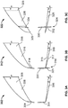
- FIGS. 3A-3C depict example wing tips (e.g., folding portions, foldable raked wing tips, etc.) 302, 312, 322 in accordance with teachings of this disclosure.
- the wing tips 302, 312, 322 can be used to implement the wing tip 114 of FIG. 1 .
- FIG. 3A the example raked foldable wing tip 302 is shown in both top and frontal views (shown together for clarity).
- the wing tip 302 includes a winglet (e.g., an up winglet) 304, which is implemented as an upwardly extending (in the frontal view of FIG. 3A ) winglet.
- a winglet e.g., an up winglet
- the wing tip 302 includes a base portion 306 and a hinge (e.g., a hinge-mounted portion/section, a fold axis portion, a hinge end, a rotational axis, etc.) 308.
- a hinge e.g., a hinge-mounted portion/section, a fold axis portion, a hinge end, a rotational axis, etc.
- the wing tip 302 exhibits a raked shape or curvature that extends along its respective lateral and vertical lengths.
- a ratio of a height of the wing tip 302 to a semi-span of the wing tip 302 is between approximately 0.2 to 0.5. Additionally or alternatively, an aspect ratio of the winglet 304 ranges from approximately 1.0 to 4.0.
- FIG. 3B depicts the example raked foldable wing tip 312 in top and frontal views.
- the example wing tip 312 includes a winglet (e.g., an up-down winglet) 314, a base portion 316 and a hinge 318.
- the winglet 314 of the illustrated extends along both upward and downward directions (in the frontal view of FIG. 3B ) from top and bottom surfaces 315, 317, respectively, of the wing 110.
- the winglet 314 includes an upper portion 320 and a lower portion 321.
- a ratio of a height of the wing tip 312 to a semi-span of the wing tip 312 is between approximately 0.3 to 0.7. Additionally or alternatively, an aspect ratio of the winglet 314 ranges from approximately 1.0 to 6.0.
- the example raked foldable wing tip 322 is shown having a winglet 324, a base portion 326 and a hinge 328.
- the winglet 324 extends both upwardly and downwardly from the wing 110, but is positioned inboard from a distal end 329 of the wing tip 322, in contrast to the winglet 314 of FIG. 3B .
- the winglet 324 of the illustrated example includes an upper portion 330 and a lower portion 332.
- a semi-spanwise location of the winglet 324 along the wing tip 322 is in a range of approximately between 0.5 to 0.9 of a semi-span of the wing tip 322.
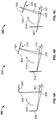
- FIGS. 4A-4C depict folding of the example wing tips 302, 312, 322 of FIGS. 3A-3C , respectively.
- FIG. 4A a frontal view of the wing tip 302 in folded and unfolded states is shown.
- the example wing tip 302 is depicted rotated about the hinge 308 from a fixed portion (e.g., a stationary portion) 401 of the wing 110 of FIG. 1 , as generally indicated by an arrow 402.
- the wing tip 302 along with the winglet 304 has been rotated to be within a span limit 404, which represents a wing span limit (e.g., a width limit) of the aircraft 100 shown in FIG. 1 .
- the wing tip 302 is rotated from an unfolded angle (e.g., a deployed angle) to approximately 90 degrees from ground (as viewed in FIG. 4A ).
- an unfolded angle e.g., a deployed angle
- the example wing tip 312 is shown along a frontal view in folded and unfolded states.
- the wing tip 312 is rotated about the hinge 318 relative to the fixed portion 401, as generally indicated by an arrow 410.
- the wing tip 312 is rotated at an angle greater than 90 degrees so that the lower portion 321 of the winglet 314 is positioned within the span limit 404.
- the wing tip 312 is rotated to an angle greater than 90 degrees from ground (as viewed in FIG. 4B ) and/or the fixed portion 401.
- FIG. 4C depicts the example wing tip 322 along a frontal view in folded and unfolded states. Similar to the example of FIG. 4B , the lower portion 332 of the winglet 324 is rotated about the hinge 328 relative to the stationary portion 401, as generally indicated by an arrow 414, so that the lower portion 332 remains within the span limit 404.
- FIGS. 5A-5B depict further example raked foldable wing tips 502, 512 in accordance with teachings of this disclosure.
- the example wing tips 502, 512 can be used to implement the wing tip 114 of FIG. 1 .
- the example wing tips 502, 512 instead, implement wing tip feather aerodynamic devices that extend along forward and aft directions of the wing 110.
- FIG. 5A the example wing tip 502 is shown in both top and frontal views (shown together for clarity).
- the wing tip 502 includes feather 504 (hereinafter feathers 504a, 504b), a base portion 506, a hinge 508 and a distal end 510.
- the feather 504a extends relatively vertical to ground (e.g., 90 degrees from ground) (in the view of FIG. 5A ).
- a tip feather joint location ranges from approximately 0.2 to 0.7 of a semi-span of the wing tip 502 (e.g. outboard from a root of the wing tip 502).
- a forward feather semi-span length divided by an aft feather semi-span length is equal to a range between approximately 0.8 to 1.2 (e.g., 1.0).
- at least one of the feathers 504a, 504b has an aspect ratio between approximately 2.0 to 5.0.
- the feathers 504a, 504b are not positioned on the wing tip 502 (e.g., the wingtips 504a, 504b are positioned inboard from the wing tip 502).
- FIG. 5B depicts the example wing tip 512 in both frontal and top views and shown in both folded and unfolded states.
- the wing tip 512 includes feathers 514 (hereinafter feathers 514a, 514b), a base portion 516, a hinge 518 and a distal end 520.
- the feather 514a is canted (e.g., exhibiting curvature in multiple planes), as opposed to the relatively vertically aligned feather 504a.
- the wing tip 512 is rotated about the hinge 518.
- the wing tip 512 is sufficiently rotated (e.g., to an angular displacement of at least 90 degrees), as generally indicated by an arrow 530, when the aircraft 100 is on the ground, for example.
- a cant angle of a forward feather ranges from between approximately 25 to 90 degrees from an aft feather.
- the forward feather is positioned higher (from ground) than the aft feather. Additionally or alternatively, the forward feather has a taller height than the aft feather.
- a tip fold location coincides with an increase and/or a transition (e.g., an inflection, a slope change, etc.) in leading edge sweep.
- feather geometry is integrated with winglet geometry (e.g., feathers are incorporated onto winglet and/or winglet shapes). In some other examples, the feathers 514a, 514b are not positioned on the wing tip 512.
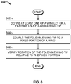
- FIG. 6 is a flowchart representative of an example method 600 to implement examples disclosed herein.
- the example method 600 can be used to install a raked foldable wing tip or folding portion(s) (e.g., the wing tips 302, 312, 322, 502, 512) onto an aircraft being manufactured or an in-service aircraft (e.g., during a retrofit and/or upgrade process).
- a winglet or a feather is defined onto the foldable raked wing tip (block 602).
- the winglet or the feather is integrally produced (e.g., die-cast, molded, etc.) on the wing tip.
- the winglet or the feather is installed or assembled to the wing tip.
- the foldable wing tip is coupled to a fixed portion of a wing.
- the foldable wing tip is assembled to a hinge that defines an interface between the fixed portion and the foldable raked wing tip.
- rotation of the foldable wing tip is verified and the process ends. For example, a rotational range of the foldable wing tip is verified to ensure that aerodynamic performance requirements are met and/or span requirements are met when the foldable wing tip is folded (e.g., folded upward).
Landscapes
- Engineering & Computer Science (AREA)
- Aviation & Aerospace Engineering (AREA)
- Mechanical Engineering (AREA)
- Physics & Mathematics (AREA)
- Fluid Mechanics (AREA)
- Tires In General (AREA)
- Toys (AREA)
Abstract
Description
- This disclosure relates generally to aircraft and, more particularly, to foldable raked wing tips having aerodynamic devices.
- In recent years, foldable wings have been implemented onto aircraft to allow for wings with relatively long wing spans. In particular, during cruise, the relatively long wing spans can result in favorable aerodynamic characteristics, such as reduced drag and, thus, reduced fuel consumption. However, these wing spans can also reduce an ability of the aircraft to comply with span requirements of airports, buildings and/or maintenance areas (e.g., gates, runways, taxi ways, taxi lanes, maintenance facilities, etc.). To maintain span requirement compliance, some aircraft employ foldable wings in which a distal portion of a wing is rotated to reduce an effective span of the aircraft while the aircraft is on the ground. As a result, aircraft with extended wing spans that employ folding can still comply with the span requirements.
- In a first aspect there is provided a wing as defined in claim 1. In a second aspect there is provided a method as defined in claim 9.
- An example wing for use with an aircraft includes a fixed portion, and a folding portion proximate a distal end of the wing. The folding portion includes a raked surface. The wing also includes at least one of a feather or a winglet, and a hinge operatively coupled between the fixed and folding portions to enable the folding portion to fold relative to the fixed portion.
- An example aerodynamic structure of an aircraft includes a fixed portion including a first raked portion, and a folding portion including a second raked portion and at least one of a winglet or a feather. The aerodynamic structure also includes a hinge operatively coupling the fixed and foldable portions to enable the foldable portion to rotate relative to the fixed portion.
- An example folding wing tip to be rotated relative to a fixed portion of a wing includes a raked portion extending along a lateral length of the folding wing tip, at least one of a winglet or a feather, and a hinge portion to be coupled to a hinge, where the hinge is to rotationally couple the folding wing tip to the fixed portion.
- An example method includes coupling a folding portion proximate to a distal portion of a wing, where the folding portion includes a raked surface, and where at least one of the folding portion includes a winglet or at least one of the wing or the folding portion includes a feather.
-
-
FIG. 1 depicts an example aircraft in which examples disclosed herein can be implemented. -
FIG. 2 is a top view of a wing tip of an example wing tip area of an aircraft ofFIG. 1 . -
FIGS. 3A-3C depict example wing tips in accordance with the teachings of this disclosure. -
FIGS. 4A-4C depict folding of the example wing tips ofFIGS. 3A-3C , respectively. -
FIGS. 5A-5B depict further example wing tips in accordance with teachings of this disclosure. -
FIG. 6 is a flowchart representative of an example method to implement examples disclosed herein. - The figures are not to scale. For example, lifting surface thicknesses depicted are not to scale. Instead, the thickness of the layers or regions may be enlarged in the drawings. In general, the same reference numbers will be used throughout the drawing(s) and accompanying written description to refer to the same or like parts. As used in this patent, stating that any part is in any way on (e.g., positioned on, located on, disposed on, or formed on, etc.) another part, indicates that the referenced part is either in contact with the other part, or that the referenced part is above the other part with one or more intermediate part(s) located therebetween. Stating that any part is in contact with another part means that there is no intermediate part between the two parts. Although the figures show layers and regions (e.g., lifting surfaces) with clean lines and boundaries, some or all of these lines and/or boundaries may be idealized. In reality, the boundaries and/or lines may be unobservable, blended, and/or irregular.
- Descriptors "first," "second," "third," etc. are used herein when identifying multiple elements or components which may be referred to separately. Unless otherwise specified or understood based on their context of use, such descriptors are not intended to impute any meaning of priority, physical order or arrangement in a list, or ordering in time but are merely used as labels for referring to multiple elements or components separately for ease of understanding the disclosed examples. In some examples, the descriptor "first" may be used to refer to an element in the detailed description, while the same element may be referred to in a claim with a different descriptor such as "second" or "third." In such instances, it should be understood that such descriptors are used merely for ease of referencing multiple elements or components.
- Foldable raked wing tips having aerodynamic devices are disclosed. Some aircraft employ folding portions (e.g., folding wing tips) for favorable aerodynamic properties while ensuring compliance with airport infrastructure requirements. For example, the folding portions at a distal end of wings of an aircraft fold upward to reduce an overall span of the aircraft to comply with the aforementioned infrastructure requirements.
- Examples disclosed herein implement a foldable raked wing tip (e.g., a foldable wing tip having a raked surface, a raked portion, a raked exterior shape, etc.) with an aerodynamic device to improve aerodynamic properties of an aircraft. In particular, the foldable raked wing tip implements at least one of a winglet or a feather, for example, to reduce an overall drag of the aircraft with reduced weight impact(s), thereby enabling significant fuel savings. Further, because the aforementioned aerodynamic device can be generally implemented as a fixed, non-movable component, implementation of the aerodynamic device is relatively cost-effective. Further, the aforementioned aerodynamic devices can be produced and/or integrated on foldable wing tips with relative ease (e.g., relatively less complex integration). In some examples, a raked portion of the foldable wing tip and at least one of a winglet or a feather mounted thereon are overlapping. In other words, in some such examples, the winglet and/or the feather are disposed on a raked portion or surface of the foldable wing tip. Additionally or alternatively, forward or aft feathers are implemented onto the foldable raked wing tip. In some examples, the foldable wing tip includes both a feather and a winglet.
- As used herein, the terms "raked, " "raked portion" and "raked surface" refer to geometries, surfaces, component shapes and/or exterior shapes exhibiting a raked curvature or a straight, swept planform shape. As used herein, the term "hinge" refers to a component, assembly and/or device used to enable rotational motion between two components. As used herein, the term "fixed portion" refers to a component, assembly and/or device that is generally fixed (i.e., translationally and rotationally fixed) and/or constrained to another component that may be moved, such as an aircraft fuselage, for example.
-
FIG. 1 depicts anexample aircraft 100 in which examples disclosed herein can be implemented. Theaircraft 100 of the illustrated example includes afuselage 102 with aflight deck 104,stabilizers 106 and afin 108. Theexample aircraft 100 also includeswings 110, both of which include acorresponding engine 112 mounted thereto. In this example, thewings 110 also includewing tips 114 located proximate distal ends of thewings 110. In this example, thewings 110, thestabilizers 106 and thefin 108 include respective control and high lift surfaces (e.g., movable control surfaces, etc.) 116. - In operation, the
aircraft 100 is maneuvered in flight by movement of thecontrol surfaces 116 in conjunction with thrust provided by theengines 112. In particular, rotational movement of thecontrol surfaces 116 affects movement and/or orientation of theaircraft 100 during flight by causing airflow changes or gradients across theaircraft 100. During cruise of theaircraft 100, thecontrol surfaces 116 are appropriately oriented and/or positioned to maintain a heading, trim, and overall aerodynamic performance of theaircraft 100. However, high drag can be encountered. Accordingly, to enhance aerodynamic performance of theaircraft 100, thewings 110 include a relatively long span that is wider than typically allowed in some airports. As will be discussed in greater detail below in connection withFIGS. 3A-5B , thewings 110 further include aerodynamic devices, such as winglets or feathers, for example, which are positioned at thewing tips 114 of therespective wings 110 for further aerodynamic performance enhancement. Accordingly, thewing tips 114 are folded relative to thewing 110 to reduce a wing span (e.g., an effective wing span) of the aircraft 100 (e.g., thewing tips 114 are folded while theaircraft 100 is on the ground). -
FIG. 2 is a top view of thewing tip 114 of theexample aircraft 100 ofFIG. 1 . In particular, theexample wing tip 114 exhibits a raked shape and/or overall geometry. Accordingly, parameters described below in connection withFIG. 2 can be related to theexample wing tip 114 or other aerodynamic features and/or components described herein. As can be seen in the illustrated example ofFIG. 2 , thewing tip 114 includes aleading edge sweep 202, which is designated by "a," and a semi-span 204, which is designated by "b." Further, thewing tip 114 has aroot chord 206 designated by "c," atip chord 208 designated by "d," and anoverall span 210, which is designated by "e." Leading and trailing edge planform shapes of thewing tip 114 can be curved or straight. - For examples disclosed herein, parameters described below can be used to characterize features associated therewith. In this example, a planform area of both
wing tips 114 can be calculated based on example Equation 1 below:
- Further, the aspect ratio of the
wing tip 114 can be calculated by example Equation 2 below:
- Moreover, taper ratios (e.g., d/c in the example shown in
Figure 2 ) can be used in characterizing examples disclosed herein. However, any appropriate equations and/or mathematical relationships can be implemented instead. - In accordance with teachings of this disclosure, example raked wing tips can exhibit an aspect ratio approximately between 1.4 to 2.5 (e.g., 1.8). In some examples, a taper ratio can range between approximately 0.20 to 0.40 (e.g., 0.28). In some examples, the leading edge sweep is approximately 40 to 70 degrees (e.g., 55 degrees).
-
FIGS. 3A-3C depict example wing tips (e.g., folding portions, foldable raked wing tips, etc.) 302, 312, 322 in accordance with teachings of this disclosure. Thewing tips wing tip 114 ofFIG. 1 . Turning toFIG. 3A , the example rakedfoldable wing tip 302 is shown in both top and frontal views (shown together for clarity). According to the illustrated example, thewing tip 302 includes a winglet (e.g., an up winglet) 304, which is implemented as an upwardly extending (in the frontal view ofFIG. 3A ) winglet. Further, thewing tip 302 includes abase portion 306 and a hinge (e.g., a hinge-mounted portion/section, a fold axis portion, a hinge end, a rotational axis, etc.) 308. In this example, thewing tip 302 exhibits a raked shape or curvature that extends along its respective lateral and vertical lengths. - In some examples, a ratio of a height of the
wing tip 302 to a semi-span of thewing tip 302 is between approximately 0.2 to 0.5. Additionally or alternatively, an aspect ratio of thewinglet 304 ranges from approximately 1.0 to 4.0. -
FIG. 3B depicts the example rakedfoldable wing tip 312 in top and frontal views. Theexample wing tip 312 includes a winglet (e.g., an up-down winglet) 314, abase portion 316 and ahinge 318. In contrast to thewinglet 304 ofFIG. 3A , thewinglet 314 of the illustrated extends along both upward and downward directions (in the frontal view ofFIG. 3B ) from top andbottom surfaces wing 110. In particular, thewinglet 314 includes anupper portion 320 and alower portion 321. - In some examples, a ratio of a height of the
wing tip 312 to a semi-span of thewing tip 312 is between approximately 0.3 to 0.7. Additionally or alternatively, an aspect ratio of thewinglet 314 ranges from approximately 1.0 to 6.0. - Turning to
FIG. 3C , the example rakedfoldable wing tip 322 is shown having awinglet 324, abase portion 326 and ahinge 328. In this example, thewinglet 324 extends both upwardly and downwardly from thewing 110, but is positioned inboard from adistal end 329 of thewing tip 322, in contrast to thewinglet 314 ofFIG. 3B . Accordingly, thewinglet 324 of the illustrated example includes anupper portion 330 and alower portion 332. - In some examples, a semi-spanwise location of the
winglet 324 along thewing tip 322 is in a range of approximately between 0.5 to 0.9 of a semi-span of thewing tip 322. -
FIGS. 4A-4C depict folding of theexample wing tips FIGS. 3A-3C , respectively. Turning toFIG. 4A , a frontal view of thewing tip 302 in folded and unfolded states is shown. In this example, theexample wing tip 302 is depicted rotated about thehinge 308 from a fixed portion (e.g., a stationary portion) 401 of thewing 110 ofFIG. 1 , as generally indicated by anarrow 402. In this example, thewing tip 302 along with thewinglet 304 has been rotated to be within aspan limit 404, which represents a wing span limit (e.g., a width limit) of theaircraft 100 shown inFIG. 1 . In particular, thewing tip 302 is rotated from an unfolded angle (e.g., a deployed angle) to approximately 90 degrees from ground (as viewed inFIG. 4A ). - Turning to
FIG. 4B , theexample wing tip 312 is shown along a frontal view in folded and unfolded states. As can be seen in the illustrated example ofFIG. 4B , thewing tip 312 is rotated about thehinge 318 relative to the fixedportion 401, as generally indicated by anarrow 410. In particular, thewing tip 312 is rotated at an angle greater than 90 degrees so that thelower portion 321 of thewinglet 314 is positioned within thespan limit 404. In this example, thewing tip 312 is rotated to an angle greater than 90 degrees from ground (as viewed inFIG. 4B ) and/or the fixedportion 401. -
FIG. 4C depicts theexample wing tip 322 along a frontal view in folded and unfolded states. Similar to the example ofFIG. 4B , thelower portion 332 of thewinglet 324 is rotated about thehinge 328 relative to thestationary portion 401, as generally indicated by anarrow 414, so that thelower portion 332 remains within thespan limit 404. -
FIGS. 5A-5B depict further example rakedfoldable wing tips example wing tips wing tip 114 ofFIG. 1 . In contrast to theexample wing tips FIGS. 3A-4C , theexample wing tips wing 110. Turning toFIG. 5A , theexample wing tip 502 is shown in both top and frontal views (shown together for clarity). According to the illustrated example, thewing tip 502 includes feather 504 (hereinafterfeathers base portion 506, ahinge 508 and adistal end 510. In this particular example, thefeather 504a extends relatively vertical to ground (e.g., 90 degrees from ground) (in the view ofFIG. 5A ). - In some examples, a tip feather joint location ranges from approximately 0.2 to 0.7 of a semi-span of the wing tip 502 (e.g. outboard from a root of the wing tip 502). In some examples that include a forward feather and an aft feather, a forward feather semi-span length divided by an aft feather semi-span length is equal to a range between approximately 0.8 to 1.2 (e.g., 1.0). In some examples, at least one of the
feathers feathers wingtips -
FIG. 5B depicts theexample wing tip 512 in both frontal and top views and shown in both folded and unfolded states. According to the illustrated example, thewing tip 512 includes feathers 514 (hereinafterfeathers base portion 516, ahinge 518 and adistal end 520. In contrast to theexample wing tip 502 ofFIG. 5A , thefeather 514a is canted (e.g., exhibiting curvature in multiple planes), as opposed to the relatively vertically alignedfeather 504a. - In operation, the
wing tip 512 is rotated about thehinge 518. To enable thedistal end 520 and thebase portion 516 to be within thespan limit 404, thewing tip 512 is sufficiently rotated (e.g., to an angular displacement of at least 90 degrees), as generally indicated by anarrow 530, when theaircraft 100 is on the ground, for example. - In some examples, a cant angle of a forward feather ranges from between approximately 25 to 90 degrees from an aft feather. In some examples, the forward feather is positioned higher (from ground) than the aft feather. Additionally or alternatively, the forward feather has a taller height than the aft feather. In some examples, a tip fold location coincides with an increase and/or a transition (e.g., an inflection, a slope change, etc.) in leading edge sweep. In some examples, feather geometry is integrated with winglet geometry (e.g., feathers are incorporated onto winglet and/or winglet shapes). In some other examples, the
feathers wing tip 512. - The aforementioned example ranges and other ranges disclosed herein with respect to
FIGS. 2-5B can be advantageous in aerodynamic efficiency (e.g., drag reduction) in folded wing tip applications, for example. However, while numerous example dimensions and parameter values have been described with respect toFIGS. 2-5B , any appropriate dimensions and/or parameter values can be implemented instead. -
FIG. 6 is a flowchart representative of anexample method 600 to implement examples disclosed herein. Theexample method 600 can be used to install a raked foldable wing tip or folding portion(s) (e.g., thewing tips - In this example, at
block 604, the foldable wing tip is coupled to a fixed portion of a wing. In particular, the foldable wing tip is assembled to a hinge that defines an interface between the fixed portion and the foldable raked wing tip. - At
block 606, in some examples, rotation of the foldable wing tip is verified and the process ends. For example, a rotational range of the foldable wing tip is verified to ensure that aerodynamic performance requirements are met and/or span requirements are met when the foldable wing tip is folded (e.g., folded upward). - Example 1 includes a wing for use with an aircraft. The wing includes a fixed portion, and a folding portion proximate a distal end of the wing. The folding portion includes a raked surface. The wing also includes at least one of a feather or a winglet, and a hinge operatively coupled between the fixed and folding portions to enable the folding portion to fold relative to the fixed portion.
- Example 2 includes the wing of Example 1, where the folding portion includes the winglet.
- Example 3 includes the wing of Example 2, where the folding portion further includes the feather.
- Example 4 includes the wing of Example 3, where the folding portion rotates to an angular displacement greater than 90 degrees from the fixed portion.
- Example 5 includes the wing of Example 2, where the folding portion further includes the feather.
- Example 6 includes the wing of Example 2, where the winglet includes a height between approximately 0.2 to 0.9 of a semi-span of the folding portion.
- Example 7 includes the wing of Example 2, where the winglet includes an aspect ratio between approximately 1.0 to 6.0.
- Example 8 includes the wing of Example 1, where the folding portion has an aspect ratio between approximately 1.4 to 2.5.
- Example 9 includes an aerodynamic structure of an aircraft. The aerodynamic structure includes a fixed portion including a first raked portion, and a folding portion with a second raked portion, and at least one of a winglet or a feather. The aerodynamic structure also includes a hinge operatively coupling the fixed and foldable portions to enable the foldable portion to rotate relative to the fixed portion.
- Example 10 includes the aerodynamic structure of Example 9, where the folding portion includes the winglet.
- Example 11 includes the aerodynamic structure of Example 10, where the winglet extends past bottom and top surfaces of the wing.
- Example 12 includes the aerodynamic structure of Example 11, where the folding portion rotates to an angular displacement greater than 90 degrees from the fixed portion.
- Example 13 includes the aerodynamic structure of Example 10, where the folding portion further includes the feather.
- Example 14 includes the aerodynamic structure of Example 10, where the winglet includes a height between approximately 0.2 to 0.9 of a semi-span of the folding portion.
- Example 15 includes the aerodynamic structure of Example 9, where the folding portion includes the feather, and where the feather has a joint location that is from approximately between 0.2 to 0.7 of a semi-span of the folding portion.
- Example 16 includes a folding wing tip to be rotated relative to a fixed portion of a wing. The folding wing tip includes a raked portion extending along a lateral length of the folding wing tip, at least one of a winglet or a feather, and a hinge portion to be coupled to a hinge, where the hinge is to rotationally couple the folding wing tip to the fixed portion.
- Example 17 includes the folding wing tip of Example 16, where the raked portion and the at least one of the winglet or the feather are overlapping.
- Example 18 includes the folding wing tip of Example 16, where the folding wing tip includes the winglet with a height between approximately 0.2 to 0.9 of a semi-span of the folding wing tip.
- Example 19 includes the folding wing tip of Example 16, where the folding wing tip has an aspect ratio between approximately 1.4 to 2.5.
- Example 20 includes the folding wing tip of Example 16, where the folding wing tip includes the feather, and where the feather has a joint location that is from approximately between 0.2 to 0.7 of a semi-span of the folding wing tip.
- Example 21 includes an example method that includes coupling a folding portion proximate to a distal portion of a wing, where the folding portion includes a raked surface, and where at least one of the folding portion includes a winglet or at least one of the wing or the folding portion includes a feather.
- Example 22 includes the method of Example 21, and further includes defining at least one of the winglet or the feather onto the folding portion.
- Example 23 includes the method of Example 21, where coupling the folding portion proximate to the distal portion of the wing includes coupling the folding portion to a hinge. From the foregoing, it will be appreciated that example methods, apparatus and articles of manufacture have been disclosed that improve aerodynamic efficiency of foldable wing tips without need for additional complex and expensive moving parts and/or control systems. Accordingly, disclosed examples enable cost-effective improvement of aerodynamic efficiency. Further, some examples disclosed herein can enable increasing of wingspans (e.g., higher span wing designs for greater aerodynamic benefits).
- Although certain example methods, apparatus and articles of manufacture have been disclosed herein, the scope of coverage of this patent is not limited thereto. On the contrary, this patent covers all methods, apparatus and articles of manufacture fairly falling within the scope of the claims of this patent. While examples disclosed herein are shown related to folding wing tips of aircraft, examples disclosed herein can be applied to any appropriate vehicle structure and/or application including, but not limited to, submersible applications, boating applications, vehicular applications, etc.
- The disclosure also includes the subject matter described in the following clauses:
- Clause 1. A wing for use with an aircraft, the wing comprising:
- a fixed portion;
- a folding portion proximate a distal end of the wing, the folding portion including a raked surface;
- at least one of a feather or a winglet; and
- a hinge operatively coupled between the fixed and folding portions to enable the folding portion to fold relative to the fixed portion.
- Clause 2. The wing as defined in clause 1, wherein the folding portion includes the winglet.
- Clause 3. The wing as defined in clause 1 or clause 2, wherein the winglet extends past bottom and top surfaces of the wing.
- Clause 4. The wing as defined in any preceding clause, wherein the folding portion rotates to an angular displacement greater than 90 degrees from the fixed portion.
- Clause 5. The wing as defined in any preceding clause, wherein the folding portion further includes the feather.
- Clause 6. The wing as defined in any preceding clause, wherein the winglet includes a height between approximately 0.2 to 0.9 of a semi-span of the folding portion.
- Clause 7. The wing as defined in any preceding clause, wherein the winglet includes an aspect ratio between approximately 1.0 to 6.0.
- Clause 8. The wing as defined in any of the preceding clauses, wherein the folding portion has an aspect ratio between approximately 1.4 to 2.5.
- Clause 9. An aerodynamic structure of an aircraft, the aerodynamic structure comprising:
- a fixed portion including a first raked portion;
- a folding portion including:
- a second raked portion, and
- at least one of a winglet or a feather; and
- a hinge operatively coupling the fixed and folding portions to enable the folding portion to rotate relative to the fixed portion.
- Clause 10. The aerodynamic structure as defined in clause 9, wherein the folding portion includes the winglet.
- Clause 11. The aerodynamic structure as defined in clause 9 or clause 10, wherein the winglet extends past bottom and top surfaces of the wing.
- Clause 12. The aerodynamic structure as defined in any of clauses 9 to 11, wherein the folding portion rotates to an angular displacement greater than 90 degrees from the fixed portion.
- Clause 13. The aerodynamic structure as defined in any of clauses 9 to 12, wherein the folding portion further includes the feather.
- Clause 14. The aerodynamic structure as defined in any of clauses 9 to 13, wherein the winglet includes a height between approximately 0.2 to 0.9 of a semi-span of the folding portion.
- Clause 15. The aerodynamic structure as defined in any of clauses 9 to 14, wherein the folding portion includes the feather, and wherein the feather has a joint location that is from approximately between 0.2 to 0.7 of a semi-span of the folding portion.
- Clause 16. A folding wing tip to be rotated relative to a fixed portion of a wing, the folding wing tip comprising:
- a raked portion extending along a lateral length of the folding wing tip;
- at least one of a winglet or a feather; and
- a hinge portion to be coupled to a hinge, the hinge to rotationally couple the folding wing tip to the fixed portion.
- Clause 17. The folding wing tip as defined in clause 16, wherein the raked portion and the at least one of the winglet or the feather are overlapping.
- Clause 18. The folding wing tip as defined in clause 16 or clause 17, wherein the folding wing tip includes the winglet with a height between approximately 0.2 to 0.9 of a semi-span of the folding wing tip.
- Clause 19. The folding wing tip as defined in any of clauses 16 to 18, wherein the folding wing tip has an aspect ratio between approximately 1.4 to 2.5.
- Clause 20. The folding wing tip as defined in any of clauses 16 to 19, wherein the folding wing tip includes the feather, and wherein the feather has a joint location that is from approximately between 0.2 to 0.7 of a semi-span of the folding wing tip.
- Clause 21. A method comprising:
coupling a folding portion proximate to a distal portion of a wing, wherein the folding portion includes a raked surface, and wherein at least one of:- the folding portion includes a winglet, or
- at least one of the wing or the folding portion includes a feather.
- Clause 22. The method as defined in clause 21, further including defining at least one of the winglet or the feather onto the folding portion.
- Clause 23. The method as defined in clause 21 or clause 22, wherein coupling the folding portion proximate to the distal portion of the wing includes coupling the folding portion to a hinge.
Claims (11)
- A wing (110) for use with an aircraft (100), the wing (110) comprising:a fixed portion (401);a folding portion (302, 312, 322, 502, 512) proximate a distal end (329, 510, 520) of the wing (110), the folding portion (302, 312, 322, 502, 512) including a raked surface;at least one of a feather (504a, 504b, 514a, 514b) and a winglet (304, 314, 324); anda hinge (308, 318, 328, 508, 518) operatively coupled between the fixed (401) and folding (302, 312, 322, 502, 512) portions to enable the folding portion (302, 312, 322, 502, 512) to fold relative to the fixed portion (401).
- The wing (110) as defined in claim 1, wherein the folding portion (302, 312, 322, 502, 512) includes the winglet (304, 314, 324).
- The wing (110) as defined in claim 2, wherein the winglet (304, 314, 324) extends past bottom (317) and top (315) surfaces of the wing (110).
- The wing (110) as defined in claim 2 or claim 3, wherein the folding portion (302, 312, 322, 502, 512) rotates to an angular displacement greater than 90 degrees from the fixed portion.
- The wing (110) as defined in any of claims 2 to 4, wherein the folding portion (302, 312, 322, 502, 512) further includes the feather (504a, 504b, 514a, 514b).
- The wing (110) as defined in any of claims 2 to 5, wherein the winglet (304, 314, 324) includes a height between approximately 0.2 to 0.9 of a semi-span of the folding portion (302, 312, 322, 502, 512).
- The wing (110) as defined in any of claims 2 to 6, wherein the winglet (304, 314, 324) includes an aspect ratio between approximately 1.0 to 6.0.
- The wing (110) as defined in any of the preceding claims, wherein the folding portion (302, 312, 322, 502, 512) has an aspect ratio between approximately 1.4 to 2.5.
- A method comprising:
coupling a folding portion (302, 312, 322, 502, 512) proximate to a distal portion of a wing (110), wherein the folding portion (302, 312, 322, 502, 512) includes a raked surface, and wherein at least one of:the folding portion (302, 312, 322, 502, 512) includes a winglet (304, 314, 324), andat least one of the wing (110) and the folding portion (302, 312, 322, 502, 512) includes a feather (504a, 504b, 514a, 514b). - The method as defined in claim 9, further including defining at least one of the winglet (304, 314, 324) and the feather (504a, 504b, 514a, 514b) onto the folding portion (302, 312, 322, 502, 512).
- The method as defined in claim 9 or claim 10, wherein coupling the folding portion (302, 312, 322, 502, 512) proximate to the distal portion of the wing (110) includes coupling the folding portion (302, 312, 322, 502, 512) to a hinge (308, 318, 328, 508, 518).
Applications Claiming Priority (1)
| Application Number | Priority Date | Filing Date | Title |
|---|---|---|---|
| US16/369,439 US11254412B2 (en) | 2019-03-29 | 2019-03-29 | Foldable raked wing tips having aerodynamic devices |
Publications (2)
| Publication Number | Publication Date |
|---|---|
| EP3718879A1 true EP3718879A1 (en) | 2020-10-07 |
| EP3718879B1 EP3718879B1 (en) | 2023-10-25 |
Family
ID=70057019
Family Applications (1)
| Application Number | Title | Priority Date | Filing Date |
|---|---|---|---|
| EP20166448.9A Active EP3718879B1 (en) | 2019-03-29 | 2020-03-27 | Foldable raked wing tips having aerodynamic devices |
Country Status (6)
| Country | Link |
|---|---|
| US (1) | US11254412B2 (en) |
| EP (1) | EP3718879B1 (en) |
| JP (1) | JP7481142B2 (en) |
| CN (1) | CN111746786B (en) |
| BR (1) | BR102020003359A2 (en) |
| CA (1) | CA3069350C (en) |
Families Citing this family (6)
| Publication number | Priority date | Publication date | Assignee | Title |
|---|---|---|---|---|
| CN112455652B (en) * | 2020-12-08 | 2022-07-01 | 吉林大学 | Multi-stage telescopic cylinder structure and telescopic cylinder type folding wing |
| US11520355B2 (en) * | 2021-02-26 | 2022-12-06 | Toyota Motor Engineering & Manufacturing North America, Inc. | Wing tip control effector |
| US11939055B2 (en) | 2022-04-15 | 2024-03-26 | Toyota Motor Engineering & Manufacturing North America, Inc. | Winglets with passive aeroelastic tailoring |
| US11932390B2 (en) | 2022-04-15 | 2024-03-19 | Toyota Motor Engineering & Manufacturing North America, Inc. | Wing shape control |
| US20260048836A1 (en) * | 2023-12-01 | 2026-02-19 | Shiang Yu LEE | Wingtip shield with strut support |
| US20260004660A1 (en) * | 2024-07-01 | 2026-01-01 | The Boeing Company | Determining the compatibility of airside infrastructure for an aircraft |
Citations (4)
| Publication number | Priority date | Publication date | Assignee | Title |
|---|---|---|---|---|
| US20090039204A1 (en) * | 2007-08-09 | 2009-02-12 | The Boeing Company | Wingtip Feathers, Including Forward Swept Feathers, and Associated Aircraft Systems and Methods |
| WO2015162399A1 (en) * | 2014-04-24 | 2015-10-29 | Airbus Operations Limited | An aircraft with a foldable wing tip device |
| GB2560900A (en) * | 2017-03-27 | 2018-10-03 | Airbus Operations Ltd | Foldable aerodynamic structure with slewing bearing |
| GB2565082A (en) * | 2017-07-31 | 2019-02-06 | Airbus Operations Ltd | Wing tip device |
Family Cites Families (72)
| Publication number | Priority date | Publication date | Assignee | Title |
|---|---|---|---|---|
| US1841921A (en) * | 1929-12-04 | 1932-01-19 | Spiegel Jacob | Airplane construction |
| GB481050A (en) | 1937-03-18 | 1938-03-04 | Short Brothers Rochester & Bedford Ltd | New or improved means for folding monoplane wings |
| US2289224A (en) | 1940-02-19 | 1942-07-07 | Douglas Aircraft Co Inc | Folding wing aircraft |
| US2290850A (en) | 1940-10-09 | 1942-07-21 | Brewster Aeronautical Corp | Folding wing airplane |
| US2418301A (en) | 1942-07-24 | 1947-04-01 | Miles Aircraft Ltd | Aircraft supporting surface |
| US2719682A (en) | 1953-02-16 | 1955-10-04 | Alfred J Handel | Foldable aircraft wing with mechanism for operating and locking the outboard section thereof |
| DE2149956C3 (en) | 1971-10-07 | 1974-03-28 | Messerschmitt-Boelkow-Blohm Gmbh, 8000 Muenchen | High lift wing |
| DE2756107C2 (en) | 1977-12-16 | 1980-02-28 | Messerschmitt-Boelkow-Blohm Gmbh, 8000 Muenchen | Highly effective vertical stabilizer with variable wing geometry |
| DE3242584A1 (en) * | 1982-11-18 | 1984-05-24 | Messerschmitt-Bölkow-Blohm GmbH, 8000 München | ARRANGEMENT OF ADDITIONAL SURFACES AT THE TIPS OF AN WING |
| US4778129A (en) | 1987-03-12 | 1988-10-18 | The Boeing Company | Control surface drive for folding wing aircraft |
| US4824053A (en) | 1987-08-27 | 1989-04-25 | Branko Sarh | Telescopic wing |
| US5072894A (en) | 1989-10-02 | 1991-12-17 | Rockwell International Corporation | Apparatus and method for increasing the angle of attack operating range of an aircraft |
| US5310138A (en) | 1991-12-30 | 1994-05-10 | Alliedsignal Inc. | Wing fold actuator system for aircraft |
| US5350135A (en) | 1992-01-30 | 1994-09-27 | The Boeing Company | Latch pin inhibitor for folding wing-tip aircraft |
| US5452643A (en) | 1992-01-30 | 1995-09-26 | The Boeing Company | Hydraulic power drive unit |
| US5381986A (en) | 1992-01-30 | 1995-01-17 | The Boeing Company | Folding wing-tip system |
| US5201479A (en) | 1992-01-30 | 1993-04-13 | The Boeing Company | Self-monitoring latch pin lock for folding wing aircraft |
| US5558299A (en) | 1994-04-19 | 1996-09-24 | Mcdonnell Douglas Corporation | Wing fold push-pin locking assembly |
| US5634613A (en) | 1994-07-18 | 1997-06-03 | Mccarthy; Peter T. | Tip vortex generation technology for creating a lift enhancing and drag reducing upwash effect |
| US6089502A (en) | 1997-06-13 | 2000-07-18 | The Boeing Company | Blunt-leading-edge raked wingtips |
| US6082665A (en) | 1998-07-27 | 2000-07-04 | Spitzer; Jeffrey J. | Roadable aircraft |
| DE19926832B4 (en) * | 1999-06-12 | 2005-09-15 | Airbus Deutschland Gmbh | Subsonic aircraft preferably with swept-up wings |
| FR2841532B1 (en) * | 2002-06-27 | 2004-12-17 | Airbus France | AIRCRAFT WITH ACTIVE WINGER TURN CONTROL |
| GB0326228D0 (en) * | 2003-11-10 | 2003-12-17 | Airbus Uk Ltd | Wing tip device |
| EP1531126B1 (en) | 2003-11-11 | 2007-02-07 | Airbus UK Limited | Wing tip device |
| US6834835B1 (en) | 2004-03-12 | 2004-12-28 | Qortek, Inc. | Telescopic wing system |
| DE102005028688A1 (en) | 2005-05-19 | 2006-11-30 | Airbus Deutschland Gmbh | Wing unit`s aerodynamic characteristics adapting device for e.g. aircraft, has winglet rotatable in relation to wing unit, such that angle between rotary axis and main direction of extension of unit differs from specified degree |
| FR2911320B1 (en) | 2007-01-16 | 2009-04-10 | Sagem Defense Securite | AIRCRAFT VESSEL IN MULTIPLE DETACHABLE ELEMENTS |
| US7744038B2 (en) * | 2007-06-15 | 2010-06-29 | The Boeing Company | Controllable winglets |
| GB0711942D0 (en) * | 2007-06-21 | 2007-08-01 | Airbus Uk Ltd | Winglet |
| US20090084904A1 (en) * | 2007-10-02 | 2009-04-02 | The Boeing Company | Wingtip Feathers, Including Paired, Fixed Feathers, and Associated Systems and Methods |
| US8083185B2 (en) | 2007-11-07 | 2011-12-27 | The Boeing Company | Aircraft wing tip having a variable incidence angle |
| US8157206B2 (en) | 2008-06-11 | 2012-04-17 | Icon Aircraft, Inc. | Two-motion wing-fold mechanism with independent load path |
| US8336830B2 (en) | 2008-10-03 | 2012-12-25 | The Boeing Company | Retractable aircraft wing tip |
| GB0919019D0 (en) | 2009-10-30 | 2009-12-16 | Airbus Operations Ltd | Aerofoil |
| EP2509862B1 (en) | 2009-12-10 | 2016-05-04 | University Of The Witwatersrand, Johannesburg | Aircraft wingtip arrangement and its method of operation |
| US8342447B2 (en) | 2010-06-15 | 2013-01-01 | The Boeing Company | Morphing control surface transition |
| GB201011843D0 (en) | 2010-07-14 | 2010-09-01 | Airbus Operations Ltd | Wing tip device |
| US9908612B2 (en) | 2011-10-01 | 2018-03-06 | The Boeing Company | Fold wing tip having stub spar |
| US9211946B2 (en) | 2011-10-01 | 2015-12-15 | The Boeing Company | Wing fold system with latch pins through multiple mating lugs |
| US9499252B2 (en) | 2011-10-01 | 2016-11-22 | The Boeing Company | Wing fold controller |
| US10538307B2 (en) * | 2011-10-01 | 2020-01-21 | The Boeing Company | Hinged raked wing tip |
| US9296469B2 (en) | 2011-10-01 | 2016-03-29 | The Boeing Company | Horizontal folding wingtip |
| US9290260B2 (en) | 2011-10-01 | 2016-03-22 | The Boeing Company | Wing fold controller |
| JP6272823B2 (en) * | 2012-04-03 | 2018-01-31 | タマラック エアロスペース グループ インコーポレイテッド | Multiple controllable airflow correction devices |
| US8733692B2 (en) | 2012-06-11 | 2014-05-27 | The Boeing Company | Latching apparatus and methods |
| EP2727826B1 (en) | 2012-10-30 | 2019-06-26 | The Boeing Company | Hinged raked wing tip |
| US9415857B2 (en) | 2012-10-30 | 2016-08-16 | The Boeing Company | Wing fold system |
| US9469392B2 (en) | 2012-10-30 | 2016-10-18 | The Boeing Company | Wing fold system rotating latch |
| US9481446B2 (en) | 2012-10-30 | 2016-11-01 | The Boeing Company | System for latching and locking a foldable airfoil |
| EP2727827B1 (en) * | 2012-10-30 | 2019-05-29 | The Boeing Company | Horizontal folding wingtip |
| US9914523B2 (en) | 2012-10-30 | 2018-03-13 | The Boeing Company | Wing hinge assembly including hinged torque boxes |
| US9296472B2 (en) | 2013-10-17 | 2016-03-29 | The Boeing Company | Wingtip control system |
| US9580166B2 (en) | 2014-01-27 | 2017-02-28 | The Boeing Company | System for latching and locking a folding wing |
| US10494082B2 (en) * | 2014-01-27 | 2019-12-03 | The Boeing Company | Systems for latching and locking a folding wing |
| US9047771B1 (en) | 2014-03-07 | 2015-06-02 | The Boeing Company | Systems and methods for ground collision avoidance |
| GB2524824B (en) | 2014-04-04 | 2020-06-24 | Airbus Operations Ltd | An aircraft wing with a wing tip device and a strut |
| US9783284B2 (en) | 2014-05-20 | 2017-10-10 | The Boeing Company | Rotary drive assembly for wing tip |
| US10227143B2 (en) * | 2014-06-12 | 2019-03-12 | The Boeing Company | Lock actuation system for aircraft |
| US9957831B2 (en) | 2014-07-31 | 2018-05-01 | The Boeing Company | Systems, methods, and apparatus for rotary vane actuators |
| US10106244B2 (en) | 2014-11-07 | 2018-10-23 | The Boeing Company | Backup system |
| GB2533413A (en) * | 2014-12-19 | 2016-06-22 | Airbus Operations Ltd | Lifting Surfaces |
| US9914524B2 (en) | 2015-01-19 | 2018-03-13 | The Boeing Company | Latch pin assembly for folding wing tip system |
| GB2540567A (en) | 2015-07-21 | 2017-01-25 | Airbus Operations Ltd | An actuator |
| US9873502B2 (en) | 2016-01-05 | 2018-01-23 | The Boeing Company | Controlling airloads on aircraft folding wing tips |
| US10215281B2 (en) | 2016-05-04 | 2019-02-26 | The Boeing Company | Seal assembly for sealing relatively movable components |
| US9919809B2 (en) | 2016-06-07 | 2018-03-20 | The Boeing Company | Folding wing system |
| CN106184710B (en) | 2016-08-18 | 2018-11-06 | 中国商用飞机有限责任公司 | Wingtip device of airplane wing |
| US10293917B2 (en) * | 2016-12-19 | 2019-05-21 | The Boeing Company | Methods and apparatus to control and monitor a folding wingtip actuation system |
| US10156439B2 (en) | 2017-03-03 | 2018-12-18 | The Boeing Company | Inspection system for alignment in restricted volumes |
| US10370084B2 (en) * | 2017-07-21 | 2019-08-06 | The Boeing Company | Methods and apparatus to adjust folding wing tips |
| GB2577303A (en) * | 2018-09-21 | 2020-03-25 | Airbus Operations Ltd | A wing tip device |
-
2019
- 2019-03-29 US US16/369,439 patent/US11254412B2/en active Active
-
2020
- 2020-01-22 CA CA3069350A patent/CA3069350C/en active Active
- 2020-02-18 BR BR102020003359-0A patent/BR102020003359A2/en unknown
- 2020-03-04 CN CN202010141223.5A patent/CN111746786B/en active Active
- 2020-03-27 EP EP20166448.9A patent/EP3718879B1/en active Active
- 2020-03-27 JP JP2020057468A patent/JP7481142B2/en active Active
Patent Citations (4)
| Publication number | Priority date | Publication date | Assignee | Title |
|---|---|---|---|---|
| US20090039204A1 (en) * | 2007-08-09 | 2009-02-12 | The Boeing Company | Wingtip Feathers, Including Forward Swept Feathers, and Associated Aircraft Systems and Methods |
| WO2015162399A1 (en) * | 2014-04-24 | 2015-10-29 | Airbus Operations Limited | An aircraft with a foldable wing tip device |
| GB2560900A (en) * | 2017-03-27 | 2018-10-03 | Airbus Operations Ltd | Foldable aerodynamic structure with slewing bearing |
| GB2565082A (en) * | 2017-07-31 | 2019-02-06 | Airbus Operations Ltd | Wing tip device |
Also Published As
| Publication number | Publication date |
|---|---|
| JP7481142B2 (en) | 2024-05-10 |
| CA3069350A1 (en) | 2020-09-29 |
| US11254412B2 (en) | 2022-02-22 |
| EP3718879B1 (en) | 2023-10-25 |
| CA3069350C (en) | 2025-09-23 |
| CN111746786A (en) | 2020-10-09 |
| CN111746786B (en) | 2025-08-22 |
| BR102020003359A2 (en) | 2020-10-13 |
| US20200307761A1 (en) | 2020-10-01 |
| JP2020172255A (en) | 2020-10-22 |
Similar Documents
| Publication | Publication Date | Title |
|---|---|---|
| US11254412B2 (en) | Foldable raked wing tips having aerodynamic devices | |
| US11964766B2 (en) | Assemblies and methods for deploying a trailing edge flap of an aircraft | |
| EP3663193B1 (en) | Curved wing tip | |
| US9637226B2 (en) | Split winglet system | |
| RU2698502C2 (en) | Bifurcated conjugated winglets | |
| EP2593362B1 (en) | Wing tip device and methods | |
| EP2397403B1 (en) | Morphing control surface transition | |
| US7971832B2 (en) | Wing tip devices | |
| CA3070845C (en) | Aircraft having foldable wings | |
| US12162588B2 (en) | High performance winglet | |
| US20070262205A1 (en) | Retractable multiple winglet | |
| EP3492374A2 (en) | Retrofit flight control surface | |
| GB2577303A (en) | A wing tip device | |
| WO2015183347A2 (en) | Flap design for fixed wing aircraft |
Legal Events
| Date | Code | Title | Description |
|---|---|---|---|
| PUAI | Public reference made under article 153(3) epc to a published international application that has entered the european phase |
Free format text: ORIGINAL CODE: 0009012 |
|
| STAA | Information on the status of an ep patent application or granted ep patent |
Free format text: STATUS: THE APPLICATION HAS BEEN PUBLISHED |
|
| AK | Designated contracting states |
Kind code of ref document: A1 Designated state(s): AL AT BE BG CH CY CZ DE DK EE ES FI FR GB GR HR HU IE IS IT LI LT LU LV MC MK MT NL NO PL PT RO RS SE SI SK SM TR |
|
| AX | Request for extension of the european patent |
Extension state: BA ME |
|
| STAA | Information on the status of an ep patent application or granted ep patent |
Free format text: STATUS: REQUEST FOR EXAMINATION WAS MADE |
|
| 17P | Request for examination filed |
Effective date: 20210407 |
|
| RBV | Designated contracting states (corrected) |
Designated state(s): AL AT BE BG CH CY CZ DE DK EE ES FI FR GB GR HR HU IE IS IT LI LT LU LV MC MK MT NL NO PL PT RO RS SE SI SK SM TR |
|
| STAA | Information on the status of an ep patent application or granted ep patent |
Free format text: STATUS: EXAMINATION IS IN PROGRESS |
|
| 17Q | First examination report despatched |
Effective date: 20210820 |
|
| GRAP | Despatch of communication of intention to grant a patent |
Free format text: ORIGINAL CODE: EPIDOSNIGR1 |
|
| STAA | Information on the status of an ep patent application or granted ep patent |
Free format text: STATUS: GRANT OF PATENT IS INTENDED |
|
| INTG | Intention to grant announced |
Effective date: 20230116 |
|
| RAP3 | Party data changed (applicant data changed or rights of an application transferred) |
Owner name: THE BOEING COMPANY |
|
| GRAJ | Information related to disapproval of communication of intention to grant by the applicant or resumption of examination proceedings by the epo deleted |
Free format text: ORIGINAL CODE: EPIDOSDIGR1 |
|
| STAA | Information on the status of an ep patent application or granted ep patent |
Free format text: STATUS: EXAMINATION IS IN PROGRESS |
|
| GRAP | Despatch of communication of intention to grant a patent |
Free format text: ORIGINAL CODE: EPIDOSNIGR1 |
|
| STAA | Information on the status of an ep patent application or granted ep patent |
Free format text: STATUS: GRANT OF PATENT IS INTENDED |
|
| INTC | Intention to grant announced (deleted) | ||
| INTG | Intention to grant announced |
Effective date: 20230531 |
|
| P01 | Opt-out of the competence of the unified patent court (upc) registered |
Effective date: 20230808 |
|
| GRAS | Grant fee paid |
Free format text: ORIGINAL CODE: EPIDOSNIGR3 |
|
| GRAA | (expected) grant |
Free format text: ORIGINAL CODE: 0009210 |
|
| STAA | Information on the status of an ep patent application or granted ep patent |
Free format text: STATUS: THE PATENT HAS BEEN GRANTED |
|
| AK | Designated contracting states |
Kind code of ref document: B1 Designated state(s): AL AT BE BG CH CY CZ DE DK EE ES FI FR GB GR HR HU IE IS IT LI LT LU LV MC MK MT NL NO PL PT RO RS SE SI SK SM TR |
|
| REG | Reference to a national code |
Ref country code: GB Ref legal event code: FG4D |
|
| REG | Reference to a national code |
Ref country code: CH Ref legal event code: EP |
|
| REG | Reference to a national code |
Ref country code: DE Ref legal event code: R096 Ref document number: 602020019672 Country of ref document: DE |
|
| REG | Reference to a national code |
Ref country code: IE Ref legal event code: FG4D |
|
| REG | Reference to a national code |
Ref country code: LT Ref legal event code: MG9D |
|
| REG | Reference to a national code |
Ref country code: NL Ref legal event code: MP Effective date: 20231025 |
|
| REG | Reference to a national code |
Ref country code: AT Ref legal event code: MK05 Ref document number: 1624418 Country of ref document: AT Kind code of ref document: T Effective date: 20231025 |
|
| PG25 | Lapsed in a contracting state [announced via postgrant information from national office to epo] |
Ref country code: NL Free format text: LAPSE BECAUSE OF FAILURE TO SUBMIT A TRANSLATION OF THE DESCRIPTION OR TO PAY THE FEE WITHIN THE PRESCRIBED TIME-LIMIT Effective date: 20231025 |
|
| PG25 | Lapsed in a contracting state [announced via postgrant information from national office to epo] |
Ref country code: GR Free format text: LAPSE BECAUSE OF FAILURE TO SUBMIT A TRANSLATION OF THE DESCRIPTION OR TO PAY THE FEE WITHIN THE PRESCRIBED TIME-LIMIT Effective date: 20240126 |
|
| PG25 | Lapsed in a contracting state [announced via postgrant information from national office to epo] |
Ref country code: IS Free format text: LAPSE BECAUSE OF FAILURE TO SUBMIT A TRANSLATION OF THE DESCRIPTION OR TO PAY THE FEE WITHIN THE PRESCRIBED TIME-LIMIT Effective date: 20240225 |
|
| PG25 | Lapsed in a contracting state [announced via postgrant information from national office to epo] |
Ref country code: LT Free format text: LAPSE BECAUSE OF FAILURE TO SUBMIT A TRANSLATION OF THE DESCRIPTION OR TO PAY THE FEE WITHIN THE PRESCRIBED TIME-LIMIT Effective date: 20231025 |
|
| PG25 | Lapsed in a contracting state [announced via postgrant information from national office to epo] |
Ref country code: AT Free format text: LAPSE BECAUSE OF FAILURE TO SUBMIT A TRANSLATION OF THE DESCRIPTION OR TO PAY THE FEE WITHIN THE PRESCRIBED TIME-LIMIT Effective date: 20231025 |
|
| PG25 | Lapsed in a contracting state [announced via postgrant information from national office to epo] |
Ref country code: ES Free format text: LAPSE BECAUSE OF FAILURE TO SUBMIT A TRANSLATION OF THE DESCRIPTION OR TO PAY THE FEE WITHIN THE PRESCRIBED TIME-LIMIT Effective date: 20231025 |
|
| PG25 | Lapsed in a contracting state [announced via postgrant information from national office to epo] |
Ref country code: LT Free format text: LAPSE BECAUSE OF FAILURE TO SUBMIT A TRANSLATION OF THE DESCRIPTION OR TO PAY THE FEE WITHIN THE PRESCRIBED TIME-LIMIT Effective date: 20231025 Ref country code: IS Free format text: LAPSE BECAUSE OF FAILURE TO SUBMIT A TRANSLATION OF THE DESCRIPTION OR TO PAY THE FEE WITHIN THE PRESCRIBED TIME-LIMIT Effective date: 20240225 Ref country code: GR Free format text: LAPSE BECAUSE OF FAILURE TO SUBMIT A TRANSLATION OF THE DESCRIPTION OR TO PAY THE FEE WITHIN THE PRESCRIBED TIME-LIMIT Effective date: 20240126 Ref country code: ES Free format text: LAPSE BECAUSE OF FAILURE TO SUBMIT A TRANSLATION OF THE DESCRIPTION OR TO PAY THE FEE WITHIN THE PRESCRIBED TIME-LIMIT Effective date: 20231025 Ref country code: BG Free format text: LAPSE BECAUSE OF FAILURE TO SUBMIT A TRANSLATION OF THE DESCRIPTION OR TO PAY THE FEE WITHIN THE PRESCRIBED TIME-LIMIT Effective date: 20240125 Ref country code: AT Free format text: LAPSE BECAUSE OF FAILURE TO SUBMIT A TRANSLATION OF THE DESCRIPTION OR TO PAY THE FEE WITHIN THE PRESCRIBED TIME-LIMIT Effective date: 20231025 Ref country code: PT Free format text: LAPSE BECAUSE OF FAILURE TO SUBMIT A TRANSLATION OF THE DESCRIPTION OR TO PAY THE FEE WITHIN THE PRESCRIBED TIME-LIMIT Effective date: 20240226 |
|
| PG25 | Lapsed in a contracting state [announced via postgrant information from national office to epo] |
Ref country code: SE Free format text: LAPSE BECAUSE OF FAILURE TO SUBMIT A TRANSLATION OF THE DESCRIPTION OR TO PAY THE FEE WITHIN THE PRESCRIBED TIME-LIMIT Effective date: 20231025 Ref country code: RS Free format text: LAPSE BECAUSE OF FAILURE TO SUBMIT A TRANSLATION OF THE DESCRIPTION OR TO PAY THE FEE WITHIN THE PRESCRIBED TIME-LIMIT Effective date: 20231025 Ref country code: PL Free format text: LAPSE BECAUSE OF FAILURE TO SUBMIT A TRANSLATION OF THE DESCRIPTION OR TO PAY THE FEE WITHIN THE PRESCRIBED TIME-LIMIT Effective date: 20231025 Ref country code: NO Free format text: LAPSE BECAUSE OF FAILURE TO SUBMIT A TRANSLATION OF THE DESCRIPTION OR TO PAY THE FEE WITHIN THE PRESCRIBED TIME-LIMIT Effective date: 20240125 Ref country code: LV Free format text: LAPSE BECAUSE OF FAILURE TO SUBMIT A TRANSLATION OF THE DESCRIPTION OR TO PAY THE FEE WITHIN THE PRESCRIBED TIME-LIMIT Effective date: 20231025 Ref country code: HR Free format text: LAPSE BECAUSE OF FAILURE TO SUBMIT A TRANSLATION OF THE DESCRIPTION OR TO PAY THE FEE WITHIN THE PRESCRIBED TIME-LIMIT Effective date: 20231025 |
|
| PG25 | Lapsed in a contracting state [announced via postgrant information from national office to epo] |
Ref country code: DK Free format text: LAPSE BECAUSE OF FAILURE TO SUBMIT A TRANSLATION OF THE DESCRIPTION OR TO PAY THE FEE WITHIN THE PRESCRIBED TIME-LIMIT Effective date: 20231025 |
|
| PG25 | Lapsed in a contracting state [announced via postgrant information from national office to epo] |
Ref country code: CZ Free format text: LAPSE BECAUSE OF FAILURE TO SUBMIT A TRANSLATION OF THE DESCRIPTION OR TO PAY THE FEE WITHIN THE PRESCRIBED TIME-LIMIT Effective date: 20231025 |
|
| REG | Reference to a national code |
Ref country code: DE Ref legal event code: R097 Ref document number: 602020019672 Country of ref document: DE |
|
| PG25 | Lapsed in a contracting state [announced via postgrant information from national office to epo] |
Ref country code: SK Free format text: LAPSE BECAUSE OF FAILURE TO SUBMIT A TRANSLATION OF THE DESCRIPTION OR TO PAY THE FEE WITHIN THE PRESCRIBED TIME-LIMIT Effective date: 20231025 |
|
| PG25 | Lapsed in a contracting state [announced via postgrant information from national office to epo] |
Ref country code: SM Free format text: LAPSE BECAUSE OF FAILURE TO SUBMIT A TRANSLATION OF THE DESCRIPTION OR TO PAY THE FEE WITHIN THE PRESCRIBED TIME-LIMIT Effective date: 20231025 Ref country code: SK Free format text: LAPSE BECAUSE OF FAILURE TO SUBMIT A TRANSLATION OF THE DESCRIPTION OR TO PAY THE FEE WITHIN THE PRESCRIBED TIME-LIMIT Effective date: 20231025 Ref country code: RO Free format text: LAPSE BECAUSE OF FAILURE TO SUBMIT A TRANSLATION OF THE DESCRIPTION OR TO PAY THE FEE WITHIN THE PRESCRIBED TIME-LIMIT Effective date: 20231025 Ref country code: IT Free format text: LAPSE BECAUSE OF FAILURE TO SUBMIT A TRANSLATION OF THE DESCRIPTION OR TO PAY THE FEE WITHIN THE PRESCRIBED TIME-LIMIT Effective date: 20231025 Ref country code: EE Free format text: LAPSE BECAUSE OF FAILURE TO SUBMIT A TRANSLATION OF THE DESCRIPTION OR TO PAY THE FEE WITHIN THE PRESCRIBED TIME-LIMIT Effective date: 20231025 Ref country code: DK Free format text: LAPSE BECAUSE OF FAILURE TO SUBMIT A TRANSLATION OF THE DESCRIPTION OR TO PAY THE FEE WITHIN THE PRESCRIBED TIME-LIMIT Effective date: 20231025 Ref country code: CZ Free format text: LAPSE BECAUSE OF FAILURE TO SUBMIT A TRANSLATION OF THE DESCRIPTION OR TO PAY THE FEE WITHIN THE PRESCRIBED TIME-LIMIT Effective date: 20231025 |
|
| PLBE | No opposition filed within time limit |
Free format text: ORIGINAL CODE: 0009261 |
|
| STAA | Information on the status of an ep patent application or granted ep patent |
Free format text: STATUS: NO OPPOSITION FILED WITHIN TIME LIMIT |
|
| 26N | No opposition filed |
Effective date: 20240726 |
|
| PG25 | Lapsed in a contracting state [announced via postgrant information from national office to epo] |
Ref country code: SI Free format text: LAPSE BECAUSE OF FAILURE TO SUBMIT A TRANSLATION OF THE DESCRIPTION OR TO PAY THE FEE WITHIN THE PRESCRIBED TIME-LIMIT Effective date: 20231025 |
|
| PG25 | Lapsed in a contracting state [announced via postgrant information from national office to epo] |
Ref country code: SI Free format text: LAPSE BECAUSE OF FAILURE TO SUBMIT A TRANSLATION OF THE DESCRIPTION OR TO PAY THE FEE WITHIN THE PRESCRIBED TIME-LIMIT Effective date: 20231025 |
|
| REG | Reference to a national code |
Ref country code: CH Ref legal event code: PL |
|
| PG25 | Lapsed in a contracting state [announced via postgrant information from national office to epo] |
Ref country code: LU Free format text: LAPSE BECAUSE OF NON-PAYMENT OF DUE FEES Effective date: 20240327 |
|
| PG25 | Lapsed in a contracting state [announced via postgrant information from national office to epo] |
Ref country code: MC Free format text: LAPSE BECAUSE OF FAILURE TO SUBMIT A TRANSLATION OF THE DESCRIPTION OR TO PAY THE FEE WITHIN THE PRESCRIBED TIME-LIMIT Effective date: 20231025 |
|
| PG25 | Lapsed in a contracting state [announced via postgrant information from national office to epo] |
Ref country code: MC Free format text: LAPSE BECAUSE OF FAILURE TO SUBMIT A TRANSLATION OF THE DESCRIPTION OR TO PAY THE FEE WITHIN THE PRESCRIBED TIME-LIMIT Effective date: 20231025 Ref country code: LU Free format text: LAPSE BECAUSE OF NON-PAYMENT OF DUE FEES Effective date: 20240327 |
|
| REG | Reference to a national code |
Ref country code: BE Ref legal event code: MM Effective date: 20240331 |
|
| PG25 | Lapsed in a contracting state [announced via postgrant information from national office to epo] |
Ref country code: BE Free format text: LAPSE BECAUSE OF NON-PAYMENT OF DUE FEES Effective date: 20240331 |
|
| PG25 | Lapsed in a contracting state [announced via postgrant information from national office to epo] |
Ref country code: IE Free format text: LAPSE BECAUSE OF NON-PAYMENT OF DUE FEES Effective date: 20240327 |
|
| PG25 | Lapsed in a contracting state [announced via postgrant information from national office to epo] |
Ref country code: IE Free format text: LAPSE BECAUSE OF NON-PAYMENT OF DUE FEES Effective date: 20240327 Ref country code: BE Free format text: LAPSE BECAUSE OF NON-PAYMENT OF DUE FEES Effective date: 20240331 Ref country code: CH Free format text: LAPSE BECAUSE OF NON-PAYMENT OF DUE FEES Effective date: 20240331 |
|
| PG25 | Lapsed in a contracting state [announced via postgrant information from national office to epo] |
Ref country code: CY Free format text: LAPSE BECAUSE OF FAILURE TO SUBMIT A TRANSLATION OF THE DESCRIPTION OR TO PAY THE FEE WITHIN THE PRESCRIBED TIME-LIMIT; INVALID AB INITIO Effective date: 20200327 |
|
| PG25 | Lapsed in a contracting state [announced via postgrant information from national office to epo] |
Ref country code: HU Free format text: LAPSE BECAUSE OF FAILURE TO SUBMIT A TRANSLATION OF THE DESCRIPTION OR TO PAY THE FEE WITHIN THE PRESCRIBED TIME-LIMIT; INVALID AB INITIO Effective date: 20200327 |
|
| PG25 | Lapsed in a contracting state [announced via postgrant information from national office to epo] |
Ref country code: FI Free format text: LAPSE BECAUSE OF FAILURE TO SUBMIT A TRANSLATION OF THE DESCRIPTION OR TO PAY THE FEE WITHIN THE PRESCRIBED TIME-LIMIT Effective date: 20231025 |
|
| PG25 | Lapsed in a contracting state [announced via postgrant information from national office to epo] |
Ref country code: TR Free format text: LAPSE BECAUSE OF FAILURE TO SUBMIT A TRANSLATION OF THE DESCRIPTION OR TO PAY THE FEE WITHIN THE PRESCRIBED TIME-LIMIT Effective date: 20231025 |
|
| PGFP | Annual fee paid to national office [announced via postgrant information from national office to epo] |
Ref country code: GB Payment date: 20260327 Year of fee payment: 7 |
|
| PGFP | Annual fee paid to national office [announced via postgrant information from national office to epo] |
Ref country code: DE Payment date: 20260327 Year of fee payment: 7 |
|
| PGFP | Annual fee paid to national office [announced via postgrant information from national office to epo] |
Ref country code: FR Payment date: 20260325 Year of fee payment: 7 |