EP3718840B1 - Improved safety valve for hydraulic brake circuit - Google Patents
Improved safety valve for hydraulic brake circuit Download PDFInfo
- Publication number
- EP3718840B1 EP3718840B1 EP20167509.7A EP20167509A EP3718840B1 EP 3718840 B1 EP3718840 B1 EP 3718840B1 EP 20167509 A EP20167509 A EP 20167509A EP 3718840 B1 EP3718840 B1 EP 3718840B1
- Authority
- EP
- European Patent Office
- Prior art keywords
- valve
- trailer
- opening
- spool
- hydraulic circuit
- Prior art date
- Legal status (The legal status is an assumption and is not a legal conclusion. Google has not performed a legal analysis and makes no representation as to the accuracy of the status listed.)
- Active
Links
Images

Classifications
-
- B—PERFORMING OPERATIONS; TRANSPORTING
- B60—VEHICLES IN GENERAL
- B60T—VEHICLE BRAKE CONTROL SYSTEMS OR PARTS THEREOF; BRAKE CONTROL SYSTEMS OR PARTS THEREOF, IN GENERAL; ARRANGEMENT OF BRAKING ELEMENTS ON VEHICLES IN GENERAL; PORTABLE DEVICES FOR PREVENTING UNWANTED MOVEMENT OF VEHICLES; VEHICLE MODIFICATIONS TO FACILITATE COOLING OF BRAKES
- B60T13/00—Transmitting braking action from initiating means to ultimate brake actuator with power assistance or drive; Brake systems incorporating such transmitting means, e.g. air-pressure brake systems
- B60T13/10—Transmitting braking action from initiating means to ultimate brake actuator with power assistance or drive; Brake systems incorporating such transmitting means, e.g. air-pressure brake systems with fluid assistance, drive, or release
- B60T13/12—Transmitting braking action from initiating means to ultimate brake actuator with power assistance or drive; Brake systems incorporating such transmitting means, e.g. air-pressure brake systems with fluid assistance, drive, or release the fluid being liquid
- B60T13/22—Brakes applied by springs or weights and released hydraulically
-
- B—PERFORMING OPERATIONS; TRANSPORTING
- B60—VEHICLES IN GENERAL
- B60T—VEHICLE BRAKE CONTROL SYSTEMS OR PARTS THEREOF; BRAKE CONTROL SYSTEMS OR PARTS THEREOF, IN GENERAL; ARRANGEMENT OF BRAKING ELEMENTS ON VEHICLES IN GENERAL; PORTABLE DEVICES FOR PREVENTING UNWANTED MOVEMENT OF VEHICLES; VEHICLE MODIFICATIONS TO FACILITATE COOLING OF BRAKES
- B60T7/00—Brake-action initiating means
- B60T7/12—Brake-action initiating means for automatic initiation; for initiation not subject to will of driver or passenger
- B60T7/20—Brake-action initiating means for automatic initiation; for initiation not subject to will of driver or passenger specially for trailers, e.g. in case of uncoupling of or overrunning by trailer
-
- B—PERFORMING OPERATIONS; TRANSPORTING
- B60—VEHICLES IN GENERAL
- B60T—VEHICLE BRAKE CONTROL SYSTEMS OR PARTS THEREOF; BRAKE CONTROL SYSTEMS OR PARTS THEREOF, IN GENERAL; ARRANGEMENT OF BRAKING ELEMENTS ON VEHICLES IN GENERAL; PORTABLE DEVICES FOR PREVENTING UNWANTED MOVEMENT OF VEHICLES; VEHICLE MODIFICATIONS TO FACILITATE COOLING OF BRAKES
- B60T13/00—Transmitting braking action from initiating means to ultimate brake actuator with power assistance or drive; Brake systems incorporating such transmitting means, e.g. air-pressure brake systems
- B60T13/10—Transmitting braking action from initiating means to ultimate brake actuator with power assistance or drive; Brake systems incorporating such transmitting means, e.g. air-pressure brake systems with fluid assistance, drive, or release
- B60T13/66—Electrical control in fluid-pressure brake systems
- B60T13/662—Electrical control in fluid-pressure brake systems characterised by specified functions of the control system components
Definitions
- the present invention relates to a trailer brake hydraulic circuit for a vehicle-trailer combination, in particular it concerns a safety valve for a hydraulic trailer brake circuit.
- a fail-safe dual line comprising a control line and of a supplementary line for controlling trailer brakes, as detailed in RVBR 2015/68, in a vehicle-trailer vehicle combination.
- Control line is used for controlling brakes in a standard operation of the trailer brake circuit and supplementary line is used for allowing a safe braking of the trailer in case of malfunctions of electrical or hydraulic components of the circuit.
- Such safety valve 1' is controlled by a balance of a first hydraulic signal X 1 ' and a second hydraulic signal X 2 '.
- First hydraulic signal X 1 ' is the pilot signal of a trailer brake valve of the braking line and it has same pressure of the vehicle braking system, e.g. it could vary from 0 to 60-80 bar depending from the model and the tractor size; while X 2 ' is taken from the output of a trailer brake valve 10' (partially shown) and may vary from 0 to 140 bar, depending from the braking action on the vehicle and the pilot ratio on the trailer brake valve..
- First signal X 2 ' is further connected to a control line brake 2' while a supplementary line brake 3' is fluidly connected to safety valve 1'.
- trailer is equipped with a positive braking device (i.e normally not braked and pressure to brake) controlled by the control line (0 bar to 140 bar), and a negative braking device (i.e. normally braked and pressure to release brake), controlled by the supplementary line (25-30 bar to 0 bar) .
- control line brake 2' is a positive brake, i.e. braking is grater proportionally to the value of the pressure of X 2 ' while supplementary line brake 3' is a negative brake, i.e. braking is greater inversely proportionally to the value of pressure applied into this latter.
- Safety valve comprises a spool 4' having three ways and two positions which are controlled by a solenoid 5' placed from pilot signal X 2 ' side and balancing pilot signal X 1 ' and a preload force given by an elastic element 6' acting concurrently with pilot signal X 1 '.
- the valve is normally open to tank, i.e. in rest condition, keeping supplementary line to 0 bar and trailer braked. When energized, it switches to working position, allowing pressure (15-35 bar) to supplementary line, releasing then trailer negative braking device..
- Valve 1' further comprises, for sake of slowing signal X 1 ' which is faster than signal X 2 ', a dumping module 8'.
- the spool 4' When the tractor park brake is off, the spool 4' is balanced among four forces, spring, pressure in X 1 ' and X 2 ' and solenoid force.
- the forces on X 1 ' and X 2 ' are present only in case of braking action on the tractor, this means that normally the solenoid only is able to win against spring and keep the spool 4' in working position, trailer therefore is unbraked.
- a first valve is a so-called “dump valve” (not shown) interposed between X 2 ' and discharge. Such valve comprises another solenoid.
- a second valve is a so-called advance valve 11', controlled by an electrical signal from the braking pedals, that allow an advanced pressure signal to the trailer brake to anticipate its spool movement and compensate the smaller trailer responsiveness compared to tractor braking system.
- the above described safety valve assembly is costly due to the presence of at least two valves (safety valve and dump valve), both provided of respective solenoids and is encumbering and complex. Moreover, there are many parts to assemble which can led to a failure.
- the above described safety valve assembly suffers of the following problem. In the braking condition it may happen that, pushing very slow or very fast the brake pedals, the signal in X 1 ' can be not synchronized with the signal in X 2 ', therefor allowing unwanted actions into the trailer, both braking or releasing brakes, depending on the vehicle dynamic.
- trailer brake circuit examples include GB2543037 A , WO2019030105 A1 or WO2012175927 A1 .
- An aim of the present invention is to satisfy the above mentioned needs.
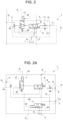
- FIG. 2 describes a first embodiment of a safety valve 1 for a trailer brake hydraulic circuit for a vehicle-trailer vehicle combination according to mother regulation RVBR 2015/68.
- a safety valve 1 for a trailer brake hydraulic circuit for a vehicle-trailer vehicle combination according to mother regulation RVBR 2015/68.
- Such compliant trailer brake hydraulic circuit is provided of a control line brake (not shown) for braking the trailer in a standard operation and a supplementary line brake (not shown) for braking the trailer in an emergency condition according to the invention.
- Safety valve 1 comprises essentially a first opening 2 fluidly connected to receive a first pilot signal X 1 derived from vehicle braking hydraulic circuit and proportional to this latter, a second opening 3 fluidly connected to the control line of the braking hydraulic circuit to derive from this latter a second pilot signal X 2 , a third opening 4 connected to a source of fluid in pressure of the vehicle, a fourth opening 5 fluidly connected to a supplementary line brake of the trailer brake hydraulic circuit and a fifth opening 6 fluidly connected to a discharge 7 of the hydraulic circuit.
- the source of fluid in pressure has preferably a substantially constant value of pressure of about 15-35 bar and the supplementary line brake is feeding preferably a negative brake, i.e. its braking increases inversely proportionally with respect to the pressure of fluid which flow to this latter.
- Valve 1 further comprises a main spool 8 fluidly interposed between third, fourth and fifth openings 4, 5, 6 and configured to assume a first position into which supplementary brake line is fluidly connected to discharge 7 and a second position into which pressure from opening 4 may flow towards supplementary brake. Accordingly, in first position of main spool 8 supplementary brake is applied, conversely in second portion of main spool 8 supplementary brake is released.
- Main spool 8 is therefore advantageously a three ways two positions spool.
- main spool 8 When braking, main spool 8 is controlled hydraulically mainly by a balance between first and second pilot signals X 1 , X 2 .
- main spool 8 is maintained in the first position by an elastic element 9 configured to push main spool 8 into such safe position.
- Main spool 8 is preferably fluidly connected to first signal X 1 via a dumping module 11 configured to slow X 1 with respect to X 2 .
- X 2 is intrinsically slower with respect to X 1 since it is generated by trailer brake valve before (see e.g. exemplarily known brake hydraulic circuit of figure 1 ).
- Dumping module 11 is therefore needed to synchronize the two pilot signals.
- dumping module 11 comprises an orifice 12 fluidly interposed in parallel with a check valve 13 between main spool 8 and first opening 2.
- Main spool 8 is advantageously fluidly connected to second signal X 2 via a selection spool 15 configured selectively allow the passage of second signal X 2 towards main spool 8.
- selection spool 15 is configured to assume a first (working) position into which signal X 2 may flow to main spool 8 and a second (resting) position into which connects main spool 8 to discharge 7.
- Advantageously selection spool 15 is a three ways two positions spool.
- selection spool 15 is maintained into the second position by an elastic element 16 configured to push selection spool 15 into such position.
- Selection spool 15 is actuated electrically, e.g. thanks to a solenoid 17 configured to receive an electric signal Z 1 derived from a park brake of the vehicle-trailer combination.
- solenoid 17 advantageously selection spool 15 with a negative logic. Indeed, if park brake is disengaged, i.e. vehicle-trailer is working, selection spool 15 is activated via solenoid 17, conversely if park brake is engaged, i.e. vehicle-trailer is stopped and parked, solenoid 17 is de-energized and therefore selection spool 15 moves thanks to the force applied by elastic element 16 into its second position.
- selection spool 15 is fluidly connected to second signal X 2 via a shuttle valve 18 further fluidly connected to the source of fluid in pressure coming from third opening 4.
- shuttle valve 18 allows the passage of the greatest signal coming into the conduit leading to main spool 8. This means to allow a pressure signal to pilot the spool 8 also when no braking action is present on the vehicle and X 2 has no pressure.
- park brake lever In a travelling condition of the vehicle-trailer system, park brake lever is not activated and therefore solenoid 17 is energized. Accordingly, selection valve 15 is placed into its first position against elastic element 16 so that second signal X 2 may flow to control main spool valve 8 to assume its second position into which supplementary brake is released.
- main spool 8 When braking, if a malfunctioning happens in trailer brake circuit so that signal X 2 decreases till becoming lower with respect to the sum of first signal X 1 and force applied by elastic element 9, than main spool 8 switches to its first position, i.e. safe position, into which supplementary brake is braked.
- park brake lever In a parking condition of the vehicle-trailer system, park brake lever is activated and therefore solenoid 17 is de-energized. Accordingly, selection valve 15 is placed into its second position, i.e. pushed by elastic element 16 so that control main spool valve 8 is fluidly connected to discharge 7 and force applied by elastic element 9, it switches to its first position, i.e. safe position, into which supplementary brake is braked.
- FIG 2A describes an alternative embodiment of the safety valve 1 described in figure 2 in which this latter comprises, integrated into this latter, an advance valve 20.
- safety valve 1 further defines a sixth opening 21 fluidly connected to a pilot port of trailer brake valve of the trailer brake hydraulic circuit.
- the advance valve 20 is fluidly connected to third, fifth and sixth openings 4, 6, 21 and it is configured to selectively allow the passage of fluid to generate a signal Y directed towards trailer brake hydraulic circuit.
- advance valve 20 is configured to assume a first position into which fluid from pressure source from opening 4 may flow to sixth opening 21 and then generate signal Y which is imparted to trailer brake valve and a second position into which signal Y is fluidly connected to discharge 7. Accordingly advance valve 20 is a three ways-two positions valve.
- Advance valve 20 is electrically actuated, e.g. by a solenoid 22 configured to overcome the load imparted by a spring 23 which is configured to maintain advance valve 20 into the first position.
- solenoid 22 is controlled by a signal Z2 imparted by electric switch of brake pedals.
- advance valve 20 is switched into its second position and starts to pressurize trailer brake valve via signal Y.
Landscapes
- Engineering & Computer Science (AREA)
- Transportation (AREA)
- Mechanical Engineering (AREA)
- Valves And Accessory Devices For Braking Systems (AREA)
- Regulating Braking Force (AREA)
- Braking Arrangements (AREA)
Description
- The present invention relates to a trailer brake hydraulic circuit for a vehicle-trailer combination, in particular it concerns a safety valve for a hydraulic trailer brake circuit.
- Mother regulation requires the presence of a fail-safe dual line comprising a control line and of a supplementary line for controlling trailer brakes, as detailed in RVBR 2015/68, in a vehicle-trailer vehicle combination. Control line is used for controlling brakes in a standard operation of the trailer brake circuit and supplementary line is used for allowing a safe braking of the trailer in case of malfunctions of electrical or hydraulic components of the circuit.
- In particular one of the possible way to implement a fails safe dual line, is the use of a safety valve for controlling the supplementary line.
- Making reference to
figures 1 and 1A , such safety valve 1' is controlled by a balance of a first hydraulic signal X1' and a second hydraulic signal X2'. First hydraulic signal X1' is the pilot signal of a trailer brake valve of the braking line and it has same pressure of the vehicle braking system, e.g. it could vary from 0 to 60-80 bar depending from the model and the tractor size; while X2' is taken from the output of atrailer brake valve 10' (partially shown) and may vary from 0 to 140 bar, depending from the braking action on the vehicle and the pilot ratio on the trailer brake valve.. - First signal X2' is further connected to a control line brake 2' while a supplementary line brake 3' is fluidly connected to safety valve 1'. In particular, as requested by mother regulation, trailer is equipped with a positive braking device (i.e normally not braked and pressure to brake) controlled by the control line (0 bar to 140 bar), and a negative braking device (i.e. normally braked and pressure to release brake), controlled by the supplementary line (25-30 bar to 0 bar) . Accordingly, control line brake 2' is a positive brake, i.e. braking is grater proportionally to the value of the pressure of X2' while supplementary line brake 3' is a negative brake, i.e. braking is greater inversely proportionally to the value of pressure applied into this latter.
- Safety valve comprises a spool 4' having three ways and two positions which are controlled by a solenoid 5' placed from pilot signal X2' side and balancing pilot signal X1' and a preload force given by an elastic element 6' acting concurrently with pilot signal X1'. The valve is normally open to tank, i.e. in rest condition, keeping supplementary line to 0 bar and trailer braked. When energized, it switches to working position, allowing pressure (15-35 bar) to supplementary line, releasing then trailer negative braking device.. Valve 1' further comprises, for sake of slowing signal X1' which is faster than signal X2', a dumping module 8'.
- When vehicle park brake is on, solenoid 5' is off and spool 4' is in rest position, with supplementary line to tank, therefore the trailer is braked.
- When the tractor park brake is off, the spool 4' is balanced among four forces, spring, pressure in X1' and X2' and solenoid force. The forces on X1' and X2' are present only in case of braking action on the tractor, this means that normally the solenoid only is able to win against spring and keep the spool 4' in working position, trailer therefore is unbraked.
- When tractor brakes, with no faults in the control system, the pressure (force) in X2' is always bigger than the pressure (force) in X1'. This means that the position of the spool cannot change and supplementary line is stable at 0 bar, therefore supplementary brake is unbraked. Only control brake line is active, indeed normal braking condition is controlled by the control line.
- When vehicle brakes but a fault is present into the control line system (electric or hydraulic), the balance on the safety is changing and the signal from X2' reduces to ideally zero. This unbalance allows the spool 4' to move to tank line and supplementary line to 0 bar, braking automatically the trailer.
- The above braking arrangement, to be fully in line with RVBR regulation, needs an another pair of valves. A first valve is a so-called "dump valve" (not shown) interposed between X2' and discharge. Such valve comprises another solenoid. A second valve is a so-called advance valve 11', controlled by an electrical signal from the braking pedals, that allow an advanced pressure signal to the trailer brake to anticipate its spool movement and compensate the smaller trailer responsiveness compared to tractor braking system.
- Therefore, the above described safety valve assembly is costly due to the presence of at least two valves (safety valve and dump valve), both provided of respective solenoids and is encumbering and complex. Moreover, there are many parts to assemble which can led to a failure.
- Further, the above described safety valve assembly suffers of the following problem. In the braking condition it may happen that, pushing very slow or very fast the brake pedals, the signal in X1' can be not synchronized with the signal in X2', therefor allowing unwanted actions into the trailer, both braking or releasing brakes, depending on the vehicle dynamic.
- Other examples of trailer brake circuit are disclosed in document
GB2543037 A WO2019030105 A1 orWO2012175927 A1 . - In view of the above, the need is felt to simplify and improve existing trailer brake hydraulic circuit and, in particular, simplify and improve existing safety valve assemblies which can allow the control of trailer brakes in a fail-safe mode.
- An aim of the present invention is to satisfy the above mentioned needs.
- The aforementioned aim is reached by a safety valve and a related trailer brake hydraulic circuit as claimed in the appended
claim 1 of the invention. - For a better understanding of the present invention, a preferred embodiment is described in the following, by way of a non-limiting example, with reference to the attached drawings wherein:
-
Figure 1 is a hydraulic scheme of part of a trailer brake hydraulic circuit comprising a safety valve according as known in the art; -
Figure 1A is a scheme of a safety valve as known in the art; -
Figure 2 is a hydraulic scheme of a safety valve according to a first embodiment of the present invention; -
Figure 2A is a hydraulic scheme of a further embodiment of the valve offigure 2 ; -
Figure 2 describes a first embodiment of asafety valve 1 for a trailer brake hydraulic circuit for a vehicle-trailer vehicle combination according to mother regulation RVBR 2015/68. Such compliant trailer brake hydraulic circuit, as known, is provided of a control line brake (not shown) for braking the trailer in a standard operation and a supplementary line brake (not shown) for braking the trailer in an emergency condition according to the invention. -
Safety valve 1 comprises essentially afirst opening 2 fluidly connected to receive a first pilot signal X1 derived from vehicle braking hydraulic circuit and proportional to this latter, asecond opening 3 fluidly connected to the control line of the braking hydraulic circuit to derive from this latter a second pilot signal X2, a third opening 4 connected to a source of fluid in pressure of the vehicle, afourth opening 5 fluidly connected to a supplementary line brake of the trailer brake hydraulic circuit and afifth opening 6 fluidly connected to adischarge 7 of the hydraulic circuit. - The source of fluid in pressure has preferably a substantially constant value of pressure of about 15-35 bar and the supplementary line brake is feeding preferably a negative brake, i.e. its braking increases inversely proportionally with respect to the pressure of fluid which flow to this latter.
- Valve 1 further comprises a
main spool 8 fluidly interposed between third, fourth andfifth openings discharge 7 and a second position into which pressure from opening 4 may flow towards supplementary brake. Accordingly, in first position ofmain spool 8 supplementary brake is applied, conversely in second portion ofmain spool 8 supplementary brake is released.Main spool 8 is therefore advantageously a three ways two positions spool. - When braking,
main spool 8 is controlled hydraulically mainly by a balance between first and second pilot signals X1, X2. In particular, in the proposed embodiment,main spool 8 is maintained in the first position by anelastic element 9 configured to pushmain spool 8 into such safe position. -
Main spool 8 is preferably fluidly connected to first signal X1 via adumping module 11 configured to slow X1 with respect to X2. Indeed X2 is intrinsically slower with respect to X1 since it is generated by trailer brake valve before (see e.g. exemplarily known brake hydraulic circuit offigure 1 ).Dumping module 11 is therefore needed to synchronize the two pilot signals. In particular,dumping module 11 comprises anorifice 12 fluidly interposed in parallel with acheck valve 13 betweenmain spool 8 andfirst opening 2. -
Main spool 8 is advantageously fluidly connected to second signal X2 via aselection spool 15 configured selectively allow the passage of second signal X2 towardsmain spool 8. In particular,selection spool 15 is configured to assume a first (working) position into which signal X2 may flow to mainspool 8 and a second (resting) position into which connectsmain spool 8 to discharge 7. Advantageouslyselection spool 15 is a three ways two positions spool. - Accordingly, in the described embodiment,
selection spool 15 is maintained into the second position by anelastic element 16 configured to pushselection spool 15 into such position. -
Selection spool 15 is actuated electrically, e.g. thanks to asolenoid 17 configured to receive an electric signal Z1 derived from a park brake of the vehicle-trailer combination. Preferably,solenoid 17 advantageously selection spool 15 with a negative logic. Indeed, if park brake is disengaged, i.e. vehicle-trailer is working,selection spool 15 is activated viasolenoid 17, conversely if park brake is engaged, i.e. vehicle-trailer is stopped and parked,solenoid 17 is de-energized and thereforeselection spool 15 moves thanks to the force applied byelastic element 16 into its second position. - In the described
embodiment selection spool 15 is fluidly connected to second signal X2 via ashuttle valve 18 further fluidly connected to the source of fluid in pressure coming from third opening 4. As known,shuttle valve 18 allows the passage of the greatest signal coming into the conduit leading tomain spool 8. This means to allow a pressure signal to pilot thespool 8 also when no braking action is present on the vehicle and X2 has no pressure. - The operation of the above described embodiment is the following.
- In a travelling condition of the vehicle-trailer system, park brake lever is not activated and therefore solenoid 17 is energized. Accordingly,
selection valve 15 is placed into its first position againstelastic element 16 so that second signal X2 may flow to controlmain spool valve 8 to assume its second position into which supplementary brake is released. When braking, if a malfunctioning happens in trailer brake circuit so that signal X2 decreases till becoming lower with respect to the sum of first signal X1 and force applied byelastic element 9, thanmain spool 8 switches to its first position, i.e. safe position, into which supplementary brake is braked. - In a parking condition of the vehicle-trailer system, park brake lever is activated and therefore solenoid 17 is de-energized. Accordingly,
selection valve 15 is placed into its second position, i.e. pushed byelastic element 16 so that controlmain spool valve 8 is fluidly connected to discharge 7 and force applied byelastic element 9, it switches to its first position, i.e. safe position, into which supplementary brake is braked. -
Figure 2A describes an alternative embodiment of thesafety valve 1 described infigure 2 in which this latter comprises, integrated into this latter, anadvance valve 20. - In particular,
safety valve 1 further defines asixth opening 21 fluidly connected to a pilot port of trailer brake valve of the trailer brake hydraulic circuit. Theadvance valve 20 is fluidly connected to third, fifth andsixth openings - In particular,
advance valve 20 is configured to assume a first position into which fluid from pressure source from opening 4 may flow tosixth opening 21 and then generate signal Y which is imparted to trailer brake valve and a second position into which signal Y is fluidly connected todischarge 7. Accordingly advancevalve 20 is a three ways-two positions valve. -
Advance valve 20 is electrically actuated, e.g. by asolenoid 22 configured to overcome the load imparted by aspring 23 which is configured to maintainadvance valve 20 into the first position. In particular,solenoid 22 is controlled by a signal Z2 imparted by electric switch of brake pedals. - The operation of the above described alternative embodiment is substantially the same of the embodiment of
figure 2 except for the operation of theadvance valve 20. - Indeed, as soon as the user touch brake pedal,
advance valve 20 is switched into its second position and starts to pressurize trailer brake valve via signal Y.
Claims (12)
- Trailer brake hydraulic circuit for a vehicle-trailer combination comprising a trailer brake valve, a control line and a supplementary line for controlling respective brakes of a trailer of said vehicle-trailer combination, said trailer brake hydraulic circuit comprising a safety valve (1), said safety valve (1) being fluidly interposed between said trailer brake valve and said supplementary line, said trailer brake hydraulic circuit being characterized in that said- safety valve (1) comprises a first opening (2) fluidly connected to receive a first pilot signal (X1) derived from vehicle-trailer braking circuit, a second opening (3) fluidly connected to receive a second pilot signal (X2) derived from said control line, a third opening (4) fluidly connected to a source of fluid in pressure of said circuit, a fourth opening (5) fluidly connected to a supplementary line brake of said trailer brake circuit and a fifth opening (6) fluidly connected to a discharge (7),
said safety valve (1) comprising:- a main spool (8) fluidly connected to said third, fourth and fifth openings (4, 5, 6) and configured to assume a first position into which said fourth opening (5) is connected to discharge (7) and a second position into which said fourth opening (5) is connected to said source of fluid in pressure, said main spool (8) being actuated hydraulically in said positions by the equilibrium between said first and second pilot signals (X1, X2), and- a selection spool (15) configured to selectively allow the passage of said second pilot signal (X2) to said main spool (8) in function of the activation of a park brake of said vehicle-trailer combination,
said selection spool (15) is an electro-actuated valve, said electro-actuated valve being actuated by an electric signal (Z1) generated in function of the status of said park brake. - Trailer brake hydraulic circuit according to claim 1, wherein said main spool (8) comprises an elastic element (9) configured to apply a force to said main spool (8) to displace this latter into said its first position.
- Trailer brake hydraulic circuit according to claim 1, wherein said main spool (8) comprises an elastic element (9) configured to apply a force to said main spool (8) to displace this latter into said its second position.
- Trailer brake hydraulic circuit according to any of the preceding claims, wherein said selection spool (15) is fluidly connected to said second and fifth openings (3, 6), to said discharge (7) and to said main spool (8) and it is configured to assume a first position into which allows the passage of fluid from said second opening (3) to said main spool (8) and a second position into which allows the passage of fluid from said second opening (3) to discharge (7).
- Trailer brake hydraulic circuit according to any of the preceding claims , wherein said selection spool (15) is a negative-logic electro actuated valve.
- Trailer brake hydraulic circuit according to claims 4 or 5, wherein said selection spool (15) comprises a elastic element (16) configured to apply a force to said selection spool (15) to displace this latter into said its first position.
- Trailer brake hydraulic circuit according to any of claims 4 or 5, wherein said selection spool (15) comprises a elastic element (16) configured to apply a force to said selection spool (15) to displace this latter into said its second position.
- Trailer brake hydraulic circuit according to any of claims 4 or 5, wherein said safety valve (1) defines a sixth opening (21) fluidly connected to said trailer brake valve and comprises an advance valve (20) integrated into said safety valve (1) and fluidly interposed between said third, fifth and sixth openings (4, 6, 21), said advance valve (20) being configured to assume a first position into which said sixth opening (21) is fluidly connected to discharge (7) and a second position into which said third opening (4) is fluidly connected to said sixth opening (21) thereby generating a signal (Y) fluidly directed towards said trailer brake valve, said advance valve (20) assuming one between the aforementioned position in function of an operative status of a brake of said vehicle-trailer combination.
- Trailer brake hydraulic circuit according to claim 8, wherein said advance valve (20) is an electro-actuated valve, said electro-actuated valve being actuated by an electric signal (Z2) generated in function of the status of said brake.
- Trailer brake hydraulic circuit according to any of the preceding claims, further comprising a dumping module (11) fluidly interposed between said first opening (2) and said main spool (8) and configured to slow said first signal (X1) with respect to said second signal (X2).
- Trailer brake hydraulic circuit according to claim 10, wherein said dumping module (11) comprises an orifice (12) fluidly in parallel to a check valve (13).
- Trailer brake hydraulic circuit according to any of the preceding claims, further comprising a shuttle valve (18) fluidly interposed between said second opening (3), said selection spool (15) and said third opening (4), said shuttle valve (18) being configured to allow the passage of the higher pressure flow coming from one between second and third openings (3, 4) to said selection spool (15).
Applications Claiming Priority (1)
| Application Number | Priority Date | Filing Date | Title |
|---|---|---|---|
| IT102019000005228A IT201900005228A1 (en) | 2019-04-05 | 2019-04-05 | IMPROVED SAFETY VALVE FOR HYDRAULIC BRAKING CIRCUIT |
Publications (2)
| Publication Number | Publication Date |
|---|---|
| EP3718840A1 EP3718840A1 (en) | 2020-10-07 |
| EP3718840B1 true EP3718840B1 (en) | 2024-06-12 |
Family
ID=67002297
Family Applications (1)
| Application Number | Title | Priority Date | Filing Date |
|---|---|---|---|
| EP20167509.7A Active EP3718840B1 (en) | 2019-04-05 | 2020-04-01 | Improved safety valve for hydraulic brake circuit |
Country Status (2)
| Country | Link |
|---|---|
| EP (1) | EP3718840B1 (en) |
| IT (1) | IT201900005228A1 (en) |
Families Citing this family (3)
| Publication number | Priority date | Publication date | Assignee | Title |
|---|---|---|---|---|
| EP4232329B1 (en) * | 2020-10-21 | 2025-02-26 | ZF CV Systems Europe BV | A trailer brake control module |
| IT202400005401A1 (en) * | 2024-03-11 | 2025-09-11 | Cnh Ind Italia Spa | IMPROVED VALVE SYSTEM FOR WORK VEHICLES |
| IT202400006109A1 (en) * | 2024-03-19 | 2025-09-19 | Cnh Ind Italia Spa | HYDRAULIC BRAKING SYSTEM FOR WORK VEHICLES |
Family Cites Families (3)
| Publication number | Priority date | Publication date | Assignee | Title |
|---|---|---|---|---|
| GB2492124B (en) * | 2011-06-22 | 2017-08-09 | Haldex Brake Prod Ab | Vehicle braking system |
| GB2543037B (en) * | 2015-10-01 | 2021-07-14 | Haldex Brake Prod Ab | Vehicle braking system and valve assembly for controlling a vehicle braking system |
| IT201700089945A1 (en) * | 2017-08-03 | 2019-02-03 | Cnh Ind Italia Spa | CONTROL CIRCUIT BRAKE OF TRAILER OF A TRACTOR |
-
2019
- 2019-04-05 IT IT102019000005228A patent/IT201900005228A1/en unknown
-
2020
- 2020-04-01 EP EP20167509.7A patent/EP3718840B1/en active Active
Also Published As
| Publication number | Publication date |
|---|---|
| IT201900005228A1 (en) | 2020-10-05 |
| EP3718840A1 (en) | 2020-10-07 |
Similar Documents
| Publication | Publication Date | Title |
|---|---|---|
| EP3564082B1 (en) | Heavy duty vehicle redundant braking system | |
| US9096206B2 (en) | Brake system for motor vehicles | |
| CN102762422B (en) | Brake fluid system and for running method and the control equipment of brake fluid system | |
| KR102310690B1 (en) | vehicle brake system | |
| RU2589199C2 (en) | Emergent braking railway system and railway vehicle | |
| CN112088115B (en) | Redundant brake unit for a brake system and system using the same | |
| EP3718840A1 (en) | Improved safety valve for hydraulic brake circuit | |
| EP3914489B1 (en) | Brake control assembly with manual and electrical actuation | |
| CN109070860B (en) | Electronically pressure-regulated vehicle brake system and method for controlling an electronically pressure-regulated vehicle brake system | |
| CN103079919A (en) | Brake system for motor vehicles | |
| KR20230042507A (en) | Electro-hydraulic brake controller for automobiles, and brake system including such brake controller | |
| JP2017520459A (en) | Automatic brake system for vehicle and operation control method for vehicle brake system | |
| CN114761295A (en) | Anti-failure valve unit for parking brake function and parking brake valve facility | |
| US10604128B2 (en) | Electronically slip-controllable braking system | |
| KR102165347B1 (en) | Motor vehicle | |
| JPWO2001030627A1 (en) | Vehicle braking system and vehicle braking device | |
| WO2019064343A1 (en) | Vehicle brake system | |
| CN111278699A (en) | Air supply source protection bypass for an electronic parking brake system and vehicle comprising such a system | |
| KR20190115063A (en) | Method and method for operating the braking system | |
| EP4188763B1 (en) | Improved hydraulic brake arrangement for off-road vehicle | |
| CN113165624B (en) | Hydraulic braking devices for off-road vehicles | |
| US20230303048A1 (en) | Vehicle brake system and method for operating a brake system | |
| EP4172010B1 (en) | Improved boosted brake control hydraulic arrangement for work vehicles | |
| CN118265640A (en) | Modules for pressure-controlled brake systems | |
| EP4606661A1 (en) | Hydraulic braking arrangement for work vehicles and related control method |
Legal Events
| Date | Code | Title | Description |
|---|---|---|---|
| PUAI | Public reference made under article 153(3) epc to a published international application that has entered the european phase |
Free format text: ORIGINAL CODE: 0009012 |
|
| STAA | Information on the status of an ep patent application or granted ep patent |
Free format text: STATUS: THE APPLICATION HAS BEEN PUBLISHED |
|
| AK | Designated contracting states |
Kind code of ref document: A1 Designated state(s): AL AT BE BG CH CY CZ DE DK EE ES FI FR GB GR HR HU IE IS IT LI LT LU LV MC MK MT NL NO PL PT RO RS SE SI SK SM TR |
|
| AX | Request for extension of the european patent |
Extension state: BA ME |
|
| STAA | Information on the status of an ep patent application or granted ep patent |
Free format text: STATUS: REQUEST FOR EXAMINATION WAS MADE |
|
| 17P | Request for examination filed |
Effective date: 20210325 |
|
| RBV | Designated contracting states (corrected) |
Designated state(s): AL AT BE BG CH CY CZ DE DK EE ES FI FR GB GR HR HU IE IS IT LI LT LU LV MC MK MT NL NO PL PT RO RS SE SI SK SM TR |
|
| GRAP | Despatch of communication of intention to grant a patent |
Free format text: ORIGINAL CODE: EPIDOSNIGR1 |
|
| STAA | Information on the status of an ep patent application or granted ep patent |
Free format text: STATUS: GRANT OF PATENT IS INTENDED |
|
| INTG | Intention to grant announced |
Effective date: 20230123 |
|
| GRAJ | Information related to disapproval of communication of intention to grant by the applicant or resumption of examination proceedings by the epo deleted |
Free format text: ORIGINAL CODE: EPIDOSDIGR1 |
|
| STAA | Information on the status of an ep patent application or granted ep patent |
Free format text: STATUS: REQUEST FOR EXAMINATION WAS MADE |
|
| GRAS | Grant fee paid |
Free format text: ORIGINAL CODE: EPIDOSNIGR3 |
|
| STAA | Information on the status of an ep patent application or granted ep patent |
Free format text: STATUS: GRANT OF PATENT IS INTENDED |
|
| INTG | Intention to grant announced |
Effective date: 20230123 |
|
| RAP3 | Party data changed (applicant data changed or rights of an application transferred) |
Owner name: CNH INDUSTRIAL ITALIA S.P.A. |
|
| GRAJ | Information related to disapproval of communication of intention to grant by the applicant or resumption of examination proceedings by the epo deleted |
Free format text: ORIGINAL CODE: EPIDOSDIGR1 |
|
| GRAL | Information related to payment of fee for publishing/printing deleted |
Free format text: ORIGINAL CODE: EPIDOSDIGR3 |
|
| STAA | Information on the status of an ep patent application or granted ep patent |
Free format text: STATUS: REQUEST FOR EXAMINATION WAS MADE |
|
| TPAC | Observations filed by third parties |
Free format text: ORIGINAL CODE: EPIDOSNTIPA |
|
| INTC | Intention to grant announced (deleted) | ||
| GRAP | Despatch of communication of intention to grant a patent |
Free format text: ORIGINAL CODE: EPIDOSNIGR1 |
|
| STAA | Information on the status of an ep patent application or granted ep patent |
Free format text: STATUS: GRANT OF PATENT IS INTENDED |
|
| INTG | Intention to grant announced |
Effective date: 20231207 |
|
| GRAA | (expected) grant |
Free format text: ORIGINAL CODE: 0009210 |
|
| STAA | Information on the status of an ep patent application or granted ep patent |
Free format text: STATUS: THE PATENT HAS BEEN GRANTED |
|
| AK | Designated contracting states |
Kind code of ref document: B1 Designated state(s): AL AT BE BG CH CY CZ DE DK EE ES FI FR GB GR HR HU IE IS IT LI LT LU LV MC MK MT NL NO PL PT RO RS SE SI SK SM TR |
|
| REG | Reference to a national code |
Ref country code: GB Ref legal event code: FG4D |
|
| REG | Reference to a national code |
Ref country code: CH Ref legal event code: EP |
|
| REG | Reference to a national code |
Ref country code: IE Ref legal event code: FG4D |
|
| REG | Reference to a national code |
Ref country code: DE Ref legal event code: R096 Ref document number: 602020032180 Country of ref document: DE |
|
| PG25 | Lapsed in a contracting state [announced via postgrant information from national office to epo] |
Ref country code: BG Free format text: LAPSE BECAUSE OF FAILURE TO SUBMIT A TRANSLATION OF THE DESCRIPTION OR TO PAY THE FEE WITHIN THE PRESCRIBED TIME-LIMIT Effective date: 20240612 |
|
| PG25 | Lapsed in a contracting state [announced via postgrant information from national office to epo] |
Ref country code: FI Free format text: LAPSE BECAUSE OF FAILURE TO SUBMIT A TRANSLATION OF THE DESCRIPTION OR TO PAY THE FEE WITHIN THE PRESCRIBED TIME-LIMIT Effective date: 20240612 Ref country code: HR Free format text: LAPSE BECAUSE OF FAILURE TO SUBMIT A TRANSLATION OF THE DESCRIPTION OR TO PAY THE FEE WITHIN THE PRESCRIBED TIME-LIMIT Effective date: 20240612 |
|
| REG | Reference to a national code |
Ref country code: LT Ref legal event code: MG9D |
|
| REG | Reference to a national code |
Ref country code: NL Ref legal event code: MP Effective date: 20240612 |
|
| PG25 | Lapsed in a contracting state [announced via postgrant information from national office to epo] |
Ref country code: ES Free format text: LAPSE BECAUSE OF FAILURE TO SUBMIT A TRANSLATION OF THE DESCRIPTION OR TO PAY THE FEE WITHIN THE PRESCRIBED TIME-LIMIT Effective date: 20240612 |
|
| PG25 | Lapsed in a contracting state [announced via postgrant information from national office to epo] |
Ref country code: LV Free format text: LAPSE BECAUSE OF FAILURE TO SUBMIT A TRANSLATION OF THE DESCRIPTION OR TO PAY THE FEE WITHIN THE PRESCRIBED TIME-LIMIT Effective date: 20240612 |
|
| PG25 | Lapsed in a contracting state [announced via postgrant information from national office to epo] |
Ref country code: NO Free format text: LAPSE BECAUSE OF FAILURE TO SUBMIT A TRANSLATION OF THE DESCRIPTION OR TO PAY THE FEE WITHIN THE PRESCRIBED TIME-LIMIT Effective date: 20240912 Ref country code: LV Free format text: LAPSE BECAUSE OF FAILURE TO SUBMIT A TRANSLATION OF THE DESCRIPTION OR TO PAY THE FEE WITHIN THE PRESCRIBED TIME-LIMIT Effective date: 20240612 Ref country code: HR Free format text: LAPSE BECAUSE OF FAILURE TO SUBMIT A TRANSLATION OF THE DESCRIPTION OR TO PAY THE FEE WITHIN THE PRESCRIBED TIME-LIMIT Effective date: 20240612 Ref country code: FI Free format text: LAPSE BECAUSE OF FAILURE TO SUBMIT A TRANSLATION OF THE DESCRIPTION OR TO PAY THE FEE WITHIN THE PRESCRIBED TIME-LIMIT Effective date: 20240612 Ref country code: ES Free format text: LAPSE BECAUSE OF FAILURE TO SUBMIT A TRANSLATION OF THE DESCRIPTION OR TO PAY THE FEE WITHIN THE PRESCRIBED TIME-LIMIT Effective date: 20240612 Ref country code: BG Free format text: LAPSE BECAUSE OF FAILURE TO SUBMIT A TRANSLATION OF THE DESCRIPTION OR TO PAY THE FEE WITHIN THE PRESCRIBED TIME-LIMIT Effective date: 20240612 Ref country code: RS Free format text: LAPSE BECAUSE OF FAILURE TO SUBMIT A TRANSLATION OF THE DESCRIPTION OR TO PAY THE FEE WITHIN THE PRESCRIBED TIME-LIMIT Effective date: 20240912 |
|
| PG25 | Lapsed in a contracting state [announced via postgrant information from national office to epo] |
Ref country code: NL Free format text: LAPSE BECAUSE OF FAILURE TO SUBMIT A TRANSLATION OF THE DESCRIPTION OR TO PAY THE FEE WITHIN THE PRESCRIBED TIME-LIMIT Effective date: 20240612 |
|
| REG | Reference to a national code |
Ref country code: AT Ref legal event code: MK05 Ref document number: 1693985 Country of ref document: AT Kind code of ref document: T Effective date: 20240612 |
|
| PG25 | Lapsed in a contracting state [announced via postgrant information from national office to epo] |
Ref country code: NL Free format text: LAPSE BECAUSE OF FAILURE TO SUBMIT A TRANSLATION OF THE DESCRIPTION OR TO PAY THE FEE WITHIN THE PRESCRIBED TIME-LIMIT Effective date: 20240612 |
|
| PG25 | Lapsed in a contracting state [announced via postgrant information from national office to epo] |
Ref country code: PT Free format text: LAPSE BECAUSE OF FAILURE TO SUBMIT A TRANSLATION OF THE DESCRIPTION OR TO PAY THE FEE WITHIN THE PRESCRIBED TIME-LIMIT Effective date: 20241014 |
|
| PG25 | Lapsed in a contracting state [announced via postgrant information from national office to epo] |
Ref country code: PT Free format text: LAPSE BECAUSE OF FAILURE TO SUBMIT A TRANSLATION OF THE DESCRIPTION OR TO PAY THE FEE WITHIN THE PRESCRIBED TIME-LIMIT Effective date: 20241014 |
|
| PG25 | Lapsed in a contracting state [announced via postgrant information from national office to epo] |
Ref country code: PL Free format text: LAPSE BECAUSE OF FAILURE TO SUBMIT A TRANSLATION OF THE DESCRIPTION OR TO PAY THE FEE WITHIN THE PRESCRIBED TIME-LIMIT Effective date: 20240612 |
|
| PG25 | Lapsed in a contracting state [announced via postgrant information from national office to epo] |
Ref country code: EE Free format text: LAPSE BECAUSE OF FAILURE TO SUBMIT A TRANSLATION OF THE DESCRIPTION OR TO PAY THE FEE WITHIN THE PRESCRIBED TIME-LIMIT Effective date: 20240612 |
|
| PG25 | Lapsed in a contracting state [announced via postgrant information from national office to epo] |
Ref country code: AT Free format text: LAPSE BECAUSE OF FAILURE TO SUBMIT A TRANSLATION OF THE DESCRIPTION OR TO PAY THE FEE WITHIN THE PRESCRIBED TIME-LIMIT Effective date: 20240612 Ref country code: IS Free format text: LAPSE BECAUSE OF FAILURE TO SUBMIT A TRANSLATION OF THE DESCRIPTION OR TO PAY THE FEE WITHIN THE PRESCRIBED TIME-LIMIT Effective date: 20241012 |
|
| PG25 | Lapsed in a contracting state [announced via postgrant information from national office to epo] |
Ref country code: CZ Free format text: LAPSE BECAUSE OF FAILURE TO SUBMIT A TRANSLATION OF THE DESCRIPTION OR TO PAY THE FEE WITHIN THE PRESCRIBED TIME-LIMIT Effective date: 20240612 |
|
| PG25 | Lapsed in a contracting state [announced via postgrant information from national office to epo] |
Ref country code: SK Free format text: LAPSE BECAUSE OF FAILURE TO SUBMIT A TRANSLATION OF THE DESCRIPTION OR TO PAY THE FEE WITHIN THE PRESCRIBED TIME-LIMIT Effective date: 20240612 Ref country code: RO Free format text: LAPSE BECAUSE OF FAILURE TO SUBMIT A TRANSLATION OF THE DESCRIPTION OR TO PAY THE FEE WITHIN THE PRESCRIBED TIME-LIMIT Effective date: 20240612 |
|
| PG25 | Lapsed in a contracting state [announced via postgrant information from national office to epo] |
Ref country code: SM Free format text: LAPSE BECAUSE OF FAILURE TO SUBMIT A TRANSLATION OF THE DESCRIPTION OR TO PAY THE FEE WITHIN THE PRESCRIBED TIME-LIMIT Effective date: 20240612 |
|
| PG25 | Lapsed in a contracting state [announced via postgrant information from national office to epo] |
Ref country code: SM Free format text: LAPSE BECAUSE OF FAILURE TO SUBMIT A TRANSLATION OF THE DESCRIPTION OR TO PAY THE FEE WITHIN THE PRESCRIBED TIME-LIMIT Effective date: 20240612 Ref country code: SK Free format text: LAPSE BECAUSE OF FAILURE TO SUBMIT A TRANSLATION OF THE DESCRIPTION OR TO PAY THE FEE WITHIN THE PRESCRIBED TIME-LIMIT Effective date: 20240612 Ref country code: RO Free format text: LAPSE BECAUSE OF FAILURE TO SUBMIT A TRANSLATION OF THE DESCRIPTION OR TO PAY THE FEE WITHIN THE PRESCRIBED TIME-LIMIT Effective date: 20240612 Ref country code: PL Free format text: LAPSE BECAUSE OF FAILURE TO SUBMIT A TRANSLATION OF THE DESCRIPTION OR TO PAY THE FEE WITHIN THE PRESCRIBED TIME-LIMIT Effective date: 20240612 Ref country code: IS Free format text: LAPSE BECAUSE OF FAILURE TO SUBMIT A TRANSLATION OF THE DESCRIPTION OR TO PAY THE FEE WITHIN THE PRESCRIBED TIME-LIMIT Effective date: 20241012 Ref country code: EE Free format text: LAPSE BECAUSE OF FAILURE TO SUBMIT A TRANSLATION OF THE DESCRIPTION OR TO PAY THE FEE WITHIN THE PRESCRIBED TIME-LIMIT Effective date: 20240612 Ref country code: CZ Free format text: LAPSE BECAUSE OF FAILURE TO SUBMIT A TRANSLATION OF THE DESCRIPTION OR TO PAY THE FEE WITHIN THE PRESCRIBED TIME-LIMIT Effective date: 20240612 Ref country code: AT Free format text: LAPSE BECAUSE OF FAILURE TO SUBMIT A TRANSLATION OF THE DESCRIPTION OR TO PAY THE FEE WITHIN THE PRESCRIBED TIME-LIMIT Effective date: 20240612 |
|
| REG | Reference to a national code |
Ref country code: DE Ref legal event code: R097 Ref document number: 602020032180 Country of ref document: DE |
|
| PG25 | Lapsed in a contracting state [announced via postgrant information from national office to epo] |
Ref country code: DK Free format text: LAPSE BECAUSE OF FAILURE TO SUBMIT A TRANSLATION OF THE DESCRIPTION OR TO PAY THE FEE WITHIN THE PRESCRIBED TIME-LIMIT Effective date: 20240612 |
|
| PLBE | No opposition filed within time limit |
Free format text: ORIGINAL CODE: 0009261 |
|
| STAA | Information on the status of an ep patent application or granted ep patent |
Free format text: STATUS: NO OPPOSITION FILED WITHIN TIME LIMIT |
|
| 26N | No opposition filed |
Effective date: 20250313 |
|
| PGFP | Annual fee paid to national office [announced via postgrant information from national office to epo] |
Ref country code: DE Payment date: 20250428 Year of fee payment: 6 |
|
| PGFP | Annual fee paid to national office [announced via postgrant information from national office to epo] |
Ref country code: GB Payment date: 20250422 Year of fee payment: 6 |
|
| PGFP | Annual fee paid to national office [announced via postgrant information from national office to epo] |
Ref country code: IT Payment date: 20250422 Year of fee payment: 6 |
|
| PGFP | Annual fee paid to national office [announced via postgrant information from national office to epo] |
Ref country code: FR Payment date: 20250424 Year of fee payment: 6 |
|
| PG25 | Lapsed in a contracting state [announced via postgrant information from national office to epo] |
Ref country code: SE Free format text: LAPSE BECAUSE OF FAILURE TO SUBMIT A TRANSLATION OF THE DESCRIPTION OR TO PAY THE FEE WITHIN THE PRESCRIBED TIME-LIMIT Effective date: 20240612 |
|
| REG | Reference to a national code |
Ref country code: CH Ref legal event code: H13 Free format text: ST27 STATUS EVENT CODE: U-0-0-H10-H13 (AS PROVIDED BY THE NATIONAL OFFICE) Effective date: 20251125 |
|
| PG25 | Lapsed in a contracting state [announced via postgrant information from national office to epo] |
Ref country code: LU Free format text: LAPSE BECAUSE OF NON-PAYMENT OF DUE FEES Effective date: 20250401 |
|
| PG25 | Lapsed in a contracting state [announced via postgrant information from national office to epo] |
Ref country code: MC Free format text: LAPSE BECAUSE OF FAILURE TO SUBMIT A TRANSLATION OF THE DESCRIPTION OR TO PAY THE FEE WITHIN THE PRESCRIBED TIME-LIMIT Effective date: 20240612 |
|
| REG | Reference to a national code |
Ref country code: BE Ref legal event code: MM Effective date: 20250430 |
|
| PG25 | Lapsed in a contracting state [announced via postgrant information from national office to epo] |
Ref country code: BE Free format text: LAPSE BECAUSE OF NON-PAYMENT OF DUE FEES Effective date: 20250430 |
|
| PG25 | Lapsed in a contracting state [announced via postgrant information from national office to epo] |
Ref country code: CH Free format text: LAPSE BECAUSE OF NON-PAYMENT OF DUE FEES Effective date: 20250430 |
|
| PG25 | Lapsed in a contracting state [announced via postgrant information from national office to epo] |
Ref country code: IE Free format text: LAPSE BECAUSE OF NON-PAYMENT OF DUE FEES Effective date: 20250401 |