EP3718774A1 - Inkjet printing apparatus - Google Patents
Inkjet printing apparatus Download PDFInfo
- Publication number
- EP3718774A1 EP3718774A1 EP20167466.0A EP20167466A EP3718774A1 EP 3718774 A1 EP3718774 A1 EP 3718774A1 EP 20167466 A EP20167466 A EP 20167466A EP 3718774 A1 EP3718774 A1 EP 3718774A1
- Authority
- EP
- European Patent Office
- Prior art keywords
- ink
- storage member
- ink storage
- printing apparatus
- inkjet printing
- Prior art date
- Legal status (The legal status is an assumption and is not a legal conclusion. Google has not performed a legal analysis and makes no representation as to the accuracy of the status listed.)
- Granted
Links
Images



Classifications
-
- B—PERFORMING OPERATIONS; TRANSPORTING
- B41—PRINTING; LINING MACHINES; TYPEWRITERS; STAMPS
- B41J—TYPEWRITERS; SELECTIVE PRINTING MECHANISMS, i.e. MECHANISMS PRINTING OTHERWISE THAN FROM A FORME; CORRECTION OF TYPOGRAPHICAL ERRORS
- B41J2/00—Typewriters or selective printing mechanisms characterised by the printing or marking process for which they are designed
- B41J2/005—Typewriters or selective printing mechanisms characterised by the printing or marking process for which they are designed characterised by bringing liquid or particles selectively into contact with a printing material
- B41J2/01—Ink jet
- B41J2/17—Ink jet characterised by ink handling
- B41J2/175—Ink supply systems ; Circuit parts therefor
- B41J2/17503—Ink cartridges
- B41J2/17543—Cartridge presence detection or type identification
-
- B—PERFORMING OPERATIONS; TRANSPORTING
- B41—PRINTING; LINING MACHINES; TYPEWRITERS; STAMPS
- B41J—TYPEWRITERS; SELECTIVE PRINTING MECHANISMS, i.e. MECHANISMS PRINTING OTHERWISE THAN FROM A FORME; CORRECTION OF TYPOGRAPHICAL ERRORS
- B41J2/00—Typewriters or selective printing mechanisms characterised by the printing or marking process for which they are designed
- B41J2/005—Typewriters or selective printing mechanisms characterised by the printing or marking process for which they are designed characterised by bringing liquid or particles selectively into contact with a printing material
- B41J2/01—Ink jet
- B41J2/17—Ink jet characterised by ink handling
- B41J2/175—Ink supply systems ; Circuit parts therefor
- B41J2/17503—Ink cartridges
- B41J2/17506—Refilling of the cartridge
- B41J2/17509—Whilst mounted in the printer
-
- B—PERFORMING OPERATIONS; TRANSPORTING
- B41—PRINTING; LINING MACHINES; TYPEWRITERS; STAMPS
- B41J—TYPEWRITERS; SELECTIVE PRINTING MECHANISMS, i.e. MECHANISMS PRINTING OTHERWISE THAN FROM A FORME; CORRECTION OF TYPOGRAPHICAL ERRORS
- B41J2/00—Typewriters or selective printing mechanisms characterised by the printing or marking process for which they are designed
- B41J2/005—Typewriters or selective printing mechanisms characterised by the printing or marking process for which they are designed characterised by bringing liquid or particles selectively into contact with a printing material
- B41J2/01—Ink jet
- B41J2/17—Ink jet characterised by ink handling
- B41J2/175—Ink supply systems ; Circuit parts therefor
- B41J2/17503—Ink cartridges
- B41J2/1752—Mounting within the printer
-
- B—PERFORMING OPERATIONS; TRANSPORTING
- B41—PRINTING; LINING MACHINES; TYPEWRITERS; STAMPS
- B41J—TYPEWRITERS; SELECTIVE PRINTING MECHANISMS, i.e. MECHANISMS PRINTING OTHERWISE THAN FROM A FORME; CORRECTION OF TYPOGRAPHICAL ERRORS
- B41J2/00—Typewriters or selective printing mechanisms characterised by the printing or marking process for which they are designed
- B41J2/005—Typewriters or selective printing mechanisms characterised by the printing or marking process for which they are designed characterised by bringing liquid or particles selectively into contact with a printing material
- B41J2/01—Ink jet
- B41J2/17—Ink jet characterised by ink handling
- B41J2/175—Ink supply systems ; Circuit parts therefor
- B41J2/17503—Ink cartridges
- B41J2/1752—Mounting within the printer
- B41J2/17523—Ink connection
-
- B—PERFORMING OPERATIONS; TRANSPORTING
- B41—PRINTING; LINING MACHINES; TYPEWRITERS; STAMPS
- B41J—TYPEWRITERS; SELECTIVE PRINTING MECHANISMS, i.e. MECHANISMS PRINTING OTHERWISE THAN FROM A FORME; CORRECTION OF TYPOGRAPHICAL ERRORS
- B41J2/00—Typewriters or selective printing mechanisms characterised by the printing or marking process for which they are designed
- B41J2/005—Typewriters or selective printing mechanisms characterised by the printing or marking process for which they are designed characterised by bringing liquid or particles selectively into contact with a printing material
- B41J2/01—Ink jet
- B41J2/17—Ink jet characterised by ink handling
- B41J2/175—Ink supply systems ; Circuit parts therefor
- B41J2/17503—Ink cartridges
- B41J2/17536—Protection of cartridges or parts thereof, e.g. tape
-
- B—PERFORMING OPERATIONS; TRANSPORTING
- B41—PRINTING; LINING MACHINES; TYPEWRITERS; STAMPS
- B41J—TYPEWRITERS; SELECTIVE PRINTING MECHANISMS, i.e. MECHANISMS PRINTING OTHERWISE THAN FROM A FORME; CORRECTION OF TYPOGRAPHICAL ERRORS
- B41J2/00—Typewriters or selective printing mechanisms characterised by the printing or marking process for which they are designed
- B41J2/005—Typewriters or selective printing mechanisms characterised by the printing or marking process for which they are designed characterised by bringing liquid or particles selectively into contact with a printing material
- B41J2/01—Ink jet
- B41J2/17—Ink jet characterised by ink handling
- B41J2/175—Ink supply systems ; Circuit parts therefor
- B41J2/17503—Ink cartridges
- B41J2/17543—Cartridge presence detection or type identification
- B41J2/17546—Cartridge presence detection or type identification electronically
-
- B—PERFORMING OPERATIONS; TRANSPORTING
- B41—PRINTING; LINING MACHINES; TYPEWRITERS; STAMPS
- B41J—TYPEWRITERS; SELECTIVE PRINTING MECHANISMS, i.e. MECHANISMS PRINTING OTHERWISE THAN FROM A FORME; CORRECTION OF TYPOGRAPHICAL ERRORS
- B41J2/00—Typewriters or selective printing mechanisms characterised by the printing or marking process for which they are designed
- B41J2/005—Typewriters or selective printing mechanisms characterised by the printing or marking process for which they are designed characterised by bringing liquid or particles selectively into contact with a printing material
- B41J2/01—Ink jet
- B41J2/17—Ink jet characterised by ink handling
- B41J2/175—Ink supply systems ; Circuit parts therefor
- B41J2/17503—Ink cartridges
- B41J2/17553—Outer structure
-
- B—PERFORMING OPERATIONS; TRANSPORTING
- B41—PRINTING; LINING MACHINES; TYPEWRITERS; STAMPS
- B41J—TYPEWRITERS; SELECTIVE PRINTING MECHANISMS, i.e. MECHANISMS PRINTING OTHERWISE THAN FROM A FORME; CORRECTION OF TYPOGRAPHICAL ERRORS
- B41J2/00—Typewriters or selective printing mechanisms characterised by the printing or marking process for which they are designed
- B41J2/005—Typewriters or selective printing mechanisms characterised by the printing or marking process for which they are designed characterised by bringing liquid or particles selectively into contact with a printing material
- B41J2/01—Ink jet
- B41J2/17—Ink jet characterised by ink handling
- B41J2/175—Ink supply systems ; Circuit parts therefor
- B41J2/17596—Ink pumps, ink valves
-
- B—PERFORMING OPERATIONS; TRANSPORTING
- B41—PRINTING; LINING MACHINES; TYPEWRITERS; STAMPS
- B41J—TYPEWRITERS; SELECTIVE PRINTING MECHANISMS, i.e. MECHANISMS PRINTING OTHERWISE THAN FROM A FORME; CORRECTION OF TYPOGRAPHICAL ERRORS
- B41J2/00—Typewriters or selective printing mechanisms characterised by the printing or marking process for which they are designed
- B41J2/005—Typewriters or selective printing mechanisms characterised by the printing or marking process for which they are designed characterised by bringing liquid or particles selectively into contact with a printing material
- B41J2/01—Ink jet
- B41J2/21—Ink jet for multi-colour printing
-
- B—PERFORMING OPERATIONS; TRANSPORTING
- B41—PRINTING; LINING MACHINES; TYPEWRITERS; STAMPS
- B41J—TYPEWRITERS; SELECTIVE PRINTING MECHANISMS, i.e. MECHANISMS PRINTING OTHERWISE THAN FROM A FORME; CORRECTION OF TYPOGRAPHICAL ERRORS
- B41J29/00—Details of, or accessories for, typewriters or selective printing mechanisms not otherwise provided for
- B41J29/02—Framework
-
- B—PERFORMING OPERATIONS; TRANSPORTING
- B41—PRINTING; LINING MACHINES; TYPEWRITERS; STAMPS
- B41J—TYPEWRITERS; SELECTIVE PRINTING MECHANISMS, i.e. MECHANISMS PRINTING OTHERWISE THAN FROM A FORME; CORRECTION OF TYPOGRAPHICAL ERRORS
- B41J29/00—Details of, or accessories for, typewriters or selective printing mechanisms not otherwise provided for
- B41J29/12—Guards, shields or dust excluders
- B41J29/13—Cases or covers
-
- C—CHEMISTRY; METALLURGY
- C09—DYES; PAINTS; POLISHES; NATURAL RESINS; ADHESIVES; COMPOSITIONS NOT OTHERWISE PROVIDED FOR; APPLICATIONS OF MATERIALS NOT OTHERWISE PROVIDED FOR
- C09D—COATING COMPOSITIONS, e.g. PAINTS, VARNISHES OR LACQUERS; FILLING PASTES; CHEMICAL PAINT OR INK REMOVERS; INKS; CORRECTING FLUIDS; WOODSTAINS; PASTES OR SOLIDS FOR COLOURING OR PRINTING; USE OF MATERIALS THEREFOR
- C09D11/00—Inks
- C09D11/30—Inkjet printing inks
- C09D11/32—Inkjet printing inks characterised by colouring agents
- C09D11/322—Pigment inks
-
- C—CHEMISTRY; METALLURGY
- C09—DYES; PAINTS; POLISHES; NATURAL RESINS; ADHESIVES; COMPOSITIONS NOT OTHERWISE PROVIDED FOR; APPLICATIONS OF MATERIALS NOT OTHERWISE PROVIDED FOR
- C09D—COATING COMPOSITIONS, e.g. PAINTS, VARNISHES OR LACQUERS; FILLING PASTES; CHEMICAL PAINT OR INK REMOVERS; INKS; CORRECTING FLUIDS; WOODSTAINS; PASTES OR SOLIDS FOR COLOURING OR PRINTING; USE OF MATERIALS THEREFOR
- C09D11/00—Inks
- C09D11/30—Inkjet printing inks
- C09D11/32—Inkjet printing inks characterised by colouring agents
- C09D11/328—Inkjet printing inks characterised by colouring agents characterised by dyes
Definitions
- the present invention relates to an inkjet printing apparatus.
- An inkjet printing apparatus performs printing by discharging ink.
- One type of inkjet printing apparatus includes a discharge head that discharges ink, and an ink storage member that stores ink to be supplied to the discharge head.
- Japanese Patent Application Laid-Open No. 2018-69696 discusses an inkjet printing apparatus that enables a user to refill an ink storage member with ink from an ink bottle. The ink is consumed by being discharged.
- an inkjet printing apparatus as specified in claims 1 to 15.
- the ink storage member capable of being refilled with ink has an ink refilling port for ink refilling. Normally, the ink refilling port is closed with a stopper member, but evaporation of the moisture in the ink from the stopper member and the periphery thereof can occur. Further, in general, an ink storage member capable of being refilled with ink has a large capacity. Therefore, this type of ink storage member is often left unused for a long time without being refilled with ink.
- the amount of evaporation of moisture from the ink storage member increases. If the evaporation of the moisture from the ink in the ink storage member thus occurs, the density (e.g., color material density) of the stored ink increases. If such ink is supplied to a discharge head and then discharged (printing is performed), the desired darkness or color tone of a printed image or character may not be achieved.
- the density e.g., color material density
- the present invention is directed to an inkjet printing apparatus that can ameliorate a change in darkness and color tone of a printed image or character due to evaporation of moisture in ink, even in a case where an ink storage member capable of being refilled with ink is used to improve usability.
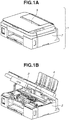
- FIGs. 1A and 1B each illustrate an example of a perspective view of the inkjet printing apparatus according to the present exemplary embodiment.
- an inkjet printing apparatus 1 has a housing 2 and a cover member 3 provided on a top surface of the housing 2.
- Fig. 1B is a diagram illustrating a state where the cover member 3 of the inkjet printing apparatus 1 is opened so that the inside of the housing 2 is visible.
- the housing 2 is substantially shaped like a rectangular parallelepiped, and includes a sheet feeding tray 4 at a rear part.
- Fig. 1B illustrates a state where the sheet feeding tray 4 is extended from the housing 2.
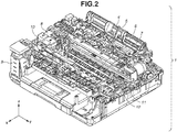
- Fig. 2 is a diagram illustrating the inside of the housing 2 of the inkjet printing apparatus 1 in Fig. 1B , in a state where the inside of the housing 2 is viewed more easily by removing an outer wall of the housing 2.
- the housing 2 includes the sheet feeding tray 4 on the rear side, as also illustrated in Figs. 1A and 1B .
- a printing medium such as a sheet of paper is to be placed on the sheet feeding tray 4.
- the housing 2 contains a first ink storage member 8 and a second ink storage member 9. Further, in the example illustrated here, a third ink storage member 10 is provided inside the housing 2. Ink is supplied from the second ink storage member 9 to the third ink storage member 10.
- the first ink storage member 8 and the third ink storage member 10 are each provided with a discharge head (not illustrated in Fig. 2 ) at a part lower in a gravitational direction. The ink is supplied from each of the first ink storage member 8 and the third ink storage member 10 to the corresponding discharge head connected thereto.
- the gravitational direction in the present specification is a z direction in Fig. 2 , and refers to a gravitational direction at the time of using the inkjet printing apparatus 1.
- the discharge head is provided with a discharge port for ink discharge, and an energy generating element that generates energy for the discharge. The discharge head discharges the ink from the discharge port, while reciprocally moving in a y direction in Fig. 2 .
- the printing medium placed on the sheet feeding tray 4 is sent by a sheet feeding roller 5 and a conveyance roller 6 in an x direction that is a frontward direction, and then supported by a platen 7 upon arriving at the platen 7.
- the printing medium supported by the platen 7 is placed at a position facing the discharge head. In this state, the ink is discharged from the discharge head to the printing medium. The discharged ink lands on the printing medium, so that an image is recorded on the printing medium.
- the ink adheres to a discharge port surface where the discharge port of the discharge head is open. Therefore, the discharge port surface can be cleaned by recovery members such as a wiper 11 and a cap 12 that are provided inside the housing 2.
- the first ink storage member 8 is provided inside the housing 2.
- the first ink storage member 8 stores color ink of cyan, magenta, and yellow colors.
- Figs. 3A and 3B each illustrate an enlarged view of the first ink storage member 8.
- Fig. 3A illustrates a state where a lid of the first ink storage member 8 is removed.
- An ink storage portion 8a stores the ink of cyan
- an ink storage portion 8b stores the ink of magenta
- an ink storage portion 8c stores the ink of yellow.
- the first ink storage member 8 has an electrical wiring member 13 for supplying power from outside to the discharge head.
- Fig. 3B is an exploded view of the first ink storage member 8, and illustrates a state where the first ink storage member 8 is viewed from an angle different from that in Fig. 3A .
- Ink absorbing members 14a, 14b, and 14c are disposed in the ink storage portions 8a, 8b, and 8c, respectively, of the first ink storage member 8.
- the ink absorbing members 14a, 14b, and 14c are sponge-like members, and each hold the ink.
- Filters 15a, 15b, and 15c are each disposed at a lower part of the corresponding one of the ink storage portions 8a, 8b, and 8c in the gravitational direction.
- the discharge head 16 is provided at a lower part of the first ink storage member 8 in the gravitational direction.
- the discharge head 16 has the energy generating element and the discharge port, and is disposed on a support member 17.
- the discharge head 16 has a discharge port array corresponding to the above-described three colors.
- the discharge head 16 of this example may also be referred to as a printing element substrate.
- the discharge head 16 is bonded to the first ink storage member 8 via the support member 17 to be integral with the first ink storage member 8.
- the discharge head 16 is driven by the power supplied from the electrical wiring member 13.
- the first ink storage member 8 is an ink cartridge not having an ink refilling port for ink refilling from the outside by a user and a stopper member for closing the ink refilling port, and detachable alone from the inkjet printing apparatus 1.
- the second ink storage member 9 is provided inside the housing 2, as with the first ink storage member 8. However, while the first ink storage member 8 does not have an ink refilling port for enabling ink refilling and a stopper member, the second ink storage member 9 has an ink refilling port for enabling ink refilling and a stopper member.
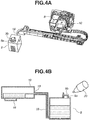
- Figs. 4A and 4B illustrate the second ink storage member 9 and a system for supplying the ink to the second ink storage member 9.
- Fig. 4A illustrates the first ink storage member 8 and the third ink storage member 10, in addition to the second ink storage member 9.
- Fig. 4B schematically illustrates the second ink storage member 9 and the third ink storage member 10.
- the second ink storage member 9 is an ink tank that has an ink refilling port 9a for enabling ink refilling, as described above.
- the ink refilling port 9a is closed with a stopper member 9b.
- the stopper member 9b is formed of, for example, rubber.
- a user opens the ink refilling port 9a by opening the stopper member 9b, and inserts an ink bottle 20 into the opened ink refilling port 9a.
- the ink bottle 20 stores ink, and the ink is supplied from the ink bottle 20 to the second ink storage member 9.
- the second ink storage member 9 is thus refilled with the external color ink.
- the second ink storage member 9 is connected to the third ink storage member 10 at a connection port 19 by a tube 18, as illustrated in Figs. 4A and 4B .
- the ink stored in the second ink storage member 9 is supplied to the third ink storage member 10 via the tube 18.
- the second ink storage member 9 and the third ink storage member 10 each store black ink is illustrated as an example.
- the third ink storage member 10 is not partitioned into three rooms, and has only one room and one corresponding filter. Otherwise, basically, the third ink storage member 10 has a configuration similar to that of the above-described first ink storage member 8.
- the discharge head 16 integral with the third ink storage member 10 is provided at a part lower of the third ink storage member 10 in the gravitational direction.
- the inside of the discharge head 16 connects to the third ink storage member 10, and discharges the ink supplied from the third ink storage member 10.
- the first ink storage member 8 provided inside the housing 2 is an ink cartridge not having an ink refilling port for enabling ink refilling by opening a stopper member, and detachable from the inkjet printing apparatus 1.
- the second ink storage member 9 similarly provided inside the housing 2 is an ink storage member having an ink refilling port for enabling refilling of the second ink storage member 9 with ink.
- the first ink storage member 8 stores, for example, color ink (ink of colors such as yellow, cyan, and magenta) that is not frequently used.
- the amount of consumption of such ink is small in many cases, and thus it is not necessary to provide an ink refilling port in the first ink storage member 8. Therefore, a change in darkness and color tone of a printed image or character due to evaporation of moisture from the ink refilling port can be inhibited.
- the first ink storage member 8 is an ink cartridge detachable from the inkjet printing apparatus 1, it is also possible to inhibit occurrence of evaporation of moisture that occurs when the stored ink is left unused for a long time.
- the second ink storage member 9 stores, for example, frequently-used black ink (ink of black color).
- the amount of consumption of such ink is large, and thus the ink refilling port is provided to enable ink refilling, so that usability can be improved.
- the inkjet printing apparatus 1 has the first ink storage member 8 and the second ink storage member 9 described above, there is provided such a configuration that refilling with a certain type of ink is enabled, while evaporation of moisture from other types of ink does not easily occur.
- the usability of ink refilling is improved, and a change in darkness and color tone of a printed image or character due to evaporation of moisture is inhibited, in the inkjet printing apparatus 1 as a whole.
- the ink stored in each of the first ink storage member 8 and the second ink storage member 9 is not determined based on the use frequency alone. This will be described in detail below.
- the first ink storage member 8 and the second ink storage member 9 are provided inside the housing 2.
- the second ink storage member 9 having the ink refilling port is provided outside the housing 2
- such a configuration leads to an increase in the size of the entire inkjet printing apparatus 1, so that usability is impaired.
- the second ink storage member 9 is provided outside the housing 2, a distance for supplying the ink from the second ink storage member 9 to the discharge head 16 increases. The increase in the distance for supplying the ink leads to easy evaporation of moisture from the ink, and thus affects an image to be printed.
- the first ink storage member 8 does not have a tube or joint from the first ink storage member 8 to the discharge head 16 in order to inhibit the evaporation of moisture from the ink.
- the evaporation of the moisture not only affects an image to be printed, but also leads to ink clogging of the discharge head 16 due to ink adhesion.
- the first ink storage member 8 can be removed from the inkjet printing apparatus 1 to be individually replaced, because the first ink storage member 8 is an ink cartridge.
- the first ink storage member 8 is an ink cartridge. Therefore, desirably, for example, the first ink storage member 8 can be removed from the inkjet printing apparatus 1, so that printing can be performed by using only the ink stored in the second ink storage member 9 having the refilling port.
- the second ink storage member 9 stores the black ink.
- the inkjet printing apparatus 1 can be used as a printing apparatus that prints a monochrome image using the black ink. In such a case, it is desirable that another member (a dummy member) different from the first ink storage member 8 be disposed in an area where the first ink storage member 8 has been disposed, in the inkjet printing apparatus 1.
- Fig. 5 is an enlarged view of the first ink storage member 8 and the second ink storage member 9 disposed inside the housing 2 of the inkjet printing apparatus 1, as viewed from above in the gravitational direction.
- the first ink storage member 8 and the second ink storage member 9 are provided on a carriage 21, and each have the discharge head 16 at a part lower in the gravitational direction.
- the first ink storage member 8 and the second ink storage member 9 each discharge the ink, while moving on the carriage 21 in a y direction.
- the inkjet printing apparatus 1 does not have the third ink storage member 10, and the first ink storage member 8 and the second ink storage member 9 are both ink cartridges.
- the second ink storage member 9 has the ink refilling port (the ink refilling port 9a) for enabling ink refilling from the ink bottle 20 by opening the stopper member, whereas the first ink storage member 8 does not have such a port.
- the inkjet printing apparatus thus configured can also inhibit a change in darkness and color tone of a printed image or character due to evaporation of moisture, while improving usability.
- a place to be accessed by the user in each of these storage members when the ink runs out is a place on the carriage 21, and the respective places are adjacent to each other. Therefore, this configuration easily improves usability, and also reduces the size of the inkjet printing apparatus.
- the second ink storage member 9 is an ink cartridge, the inkjet printing apparatus described with reference to Figs. 4A and 4B is more desirable to increase the capacity for the ink to be stored in the second ink storage member 9.
- the discharge head is disposed at the lower part of each of the first ink storage member 8 and the third ink storage member 10 in the gravitational direction.
- the second ink storage member 9 and the discharge head are on the same side (the -y side), in a direction (the y direction) orthogonal to a conveyance direction for the printing medium of the inkjet printing apparatus 1. If the second ink storage member 9 is refilled with the ink in such a state, each of the first ink storage member 8 and the third ink storage member 10 on the respective discharge heads can also be replaced when the refilling is performed.
- the user can easily add the ink (refilling and replacement) at a time.
- a configuration can be implemented by, for example, scanning the position of the discharge head on the carriage, when the user refills the second ink storage member 9 with the ink (e.g., when the user inputs an instruction for refilling, or opening of the stopper member is detected by the printing apparatus).
- the second ink storage member 9 and the discharge head are on the same side, it is easy for the user to can carry out the refilling when replacing each of the first ink storage member 8 and the third ink storage member 10, i.e., the user can easily add the ink (refilling and replacement) at a time.
- the discharge head can be brought to the end portion on the +y side, in the state illustrated in Fig. 2 .
- the second ink storage member 9 and the discharge head are on the opposite sides (the -y side and the +y side), in the y direction of the inkjet printing apparatus 1. If the second ink storage member 9 is refilled with the ink in such a state, the ink does not easily attach to the discharge head, the first ink storage member 8, and the third ink storage member 10, when the second ink storage member 9 is refilled with the ink.
- the user can be prevented from replacing the first ink storage member 8 or the third ink storage member 10 by mistake, when refilling the second ink storage member 9 with the ink.
- the user can be prevented from carrying out the ink refilling by opening the stopper member of the second ink storage member 9 by mistake, when trying to replace the first ink storage member 8 or the third ink storage member 10.
- the discharge head, the first ink storage member 8, and the third ink storage member 10 are covered with, for example, a member of the housing, when the user refills the second ink storage member 9 with the ink.
- the second ink storage member 9 is covered with, for example, a member of the housing, when the user replaces the first ink storage member 8 or the third ink storage member 10.
- Fig. 6A illustrates the ink storage members on the carriage in a manner similar to Fig. 5 .
- the first ink storage member 8 and the third ink storage member 10 are provided on the carriage 21.
- the first ink storage member 8 is an ink cartridge not having an ink refilling port and detachable from the inkjet printing apparatus 1.
- the third ink storage member 10 includes four storage members 10Y, 10M, 10C, and 10Bk that store yellow ink, magenta ink, cyan ink, and black ink, respectively.
- the third ink storage member 10 is connected to the second ink storage member (not illustrated) within the housing 2 by the tube 18.
- the second ink storage member is a storage member having an ink refilling port such as the one described with reference to Figs. 4A and 4B , and has four ink storage portions corresponding to the respective colors.
- the second ink storage member is provided with four ink refilling ports for the respective ink storage portions, and can be refilled with the ink for each color from an ink bottle.
- the first ink storage member 8 stores ink of color different from the above-described four colors.
- the discharge head 16 common to the storage members 10Y, 10M, 10C, and 10Bk is provided at a lower part of the third ink storage member 10 in the gravitational direction.
- the third ink storage member 10 and the discharge head 16 are not integral with each other, and the third ink storage member 10 can be removed for detachment/attachment or for replacement, independently of the discharge head 16.
- the discharge head (not illustrated) is provided at the lower part of the first ink storage member 8 in the gravitational direction as well.
- the discharge head at the lower part of the first ink storage member 8 in the gravitational direction is integral with the first ink storage member 8 similar to the one illustrated in Fig. 4B .
- Fig. 6B illustrates a configuration basically similar to that in Fig. 6A .
- the discharge head at the lower part of the first ink storage member 8 in the gravitational direction and the discharge head at the part lower of the third ink storage member 10 in the gravitational direction form the common discharge head 16.
- the first ink storage member 8 and the discharge head 16 are not integral with each other, and the first ink storage member 8 can also be removed for attachment/detachment independently of the discharge head 16, as with the third ink storage member 10.
- the first ink storage member 8 in this example is connected to the second ink storage member (not illustrated) having a refilling port by the tube 18, as with the third ink storage member 10.
- Such a configuration makes the carriage 21 smaller than that in the configuration illustrated in Fig. 6A , so that the size of the entire inkjet printing apparatus is easily reduced.
- the discharge head 16 common to the ink storage members is used, it is necessary to replace the discharge head 16 collectively including portions that discharge ink of all colors, even if replacement of the discharge head 16 is necessary for only a portion that discharges ink of a certain color.
- the second ink storage member is omitted, but the second ink storage member is present on the right side in Fig. 6A .
- the third ink storage member 10 is disposed at a closer position to the second ink storage member than the first ink storage member 8.
- the first ink storage member 8 is an ink cartridge, but it is necessary to provide a supply path for ink such as a tube between the second ink storage member and the third ink storage member 10, and thus evaporation of moisture from the supply path is conceivable.
- the third ink storage member 10 is provided at a closer position to the second ink storage member than the first ink storage member 8, so that the distance from the second ink storage member to the third ink storage member 10 can be as short as possible. In other words, the amount of evaporation of moisture in the ink from the supply path can be small.
- the second ink storage member is present on the right side in Fig. 6B .
- the third ink storage member 10 in a case where the first ink storage member 8 and the third ink storage member 10 are on the same discharge head 16, it is desirable to provide the third ink storage member 10 at a closer position to the second ink storage member than the first ink storage member 8, in terms of inhibition of the evaporation of the moisture.
- FIG. 7 schematically illustrates each of the ink storage members.
- the carriage 21 and the ink storage members on the carriage 21 are illustrated in a manner similar to Fig. 5 , at a center of Fig. 7 .
- the third ink storage member 10 and a fourth ink storage member 22 are provided on the carriage 21.
- the third ink storage member 10 includes the four storage members 10Y, 10M, 10C, and 10Bk that store yellow ink, magenta ink, cyan ink, and black ink, respectively.
- the discharge head at the lower part of the third ink storage member 10 in the gravitational direction and that of the fourth ink storage member 22 form the common discharge head 16.
- the third ink storage member 10 is connected to the second ink storage member 9 within the housing 2 by the tube 18.
- the second ink storage member 9 includes four storage members 9Y, 9M, 9C, and 9Bk that store yellow ink, magenta ink, cyan ink, and black ink, respectively.
- the storage members 10Y, 10M, 10C, and 10Bk are connected to the storage members 9Y, 9M, 9C, and 9Bk, respectively, by the respective tubes 18.
- the storage members 9Y, 9M, 9C, and 9Bk are provided with ink refilling ports 9Ya, 9Ma, 9Ca, and 9Bka, respectively, and can each be refilled with the ink from the ink bottle 20.
- the ink bottle 20 also includes four types of ink bottles 20Y, 20M, 20C, and 20Bk.
- the fourth ink storage member 22 is connected to the first ink storage member 8 via the tube 18.
- the first ink storage member 8 is also provided inside the housing 2. The first ink storage member 8 can be detached from the inkjet printing apparatus 1, by pulling out the first ink storage member 8 from a leading end portion 23 of the tube 18.
- the first ink storage member 8 in this example is also an ink cartridge detachable from the inkjet printing apparatus 1.
- Neither of the first ink storage member 8 and the fourth ink storage member 22 is provided with an ink refilling port. Therefore, evaporation of moisture from the ink can be further inhibited.
- the first ink storage member 8 can be replaced by being detached from the inkjet printing apparatus 1, even during discharge of the ink (printing) by the discharge head 16.
- the fourth ink storage member 22 stores the ink that is hard to increase on the carriage 21, the amount of this ink can be increased in the outside of the fourth ink storage member 22, by providing the first ink storage member 8.
- the ink stored in the first ink storage member and the ink stored in the second ink storage member will be described.
- the ink stored in each of the storage members is not limited to a particular type.
- the first ink storage member is an ink cartridge not having an ink refilling port
- the second ink storage member is a storage member having an ink refilling port
- the ink stored in the first ink storage member is first ink
- the ink stored in the second ink storage member is second ink.
- the first ink storage member is an ink cartridge not having an ink refilling port, and thus evaporation of moisture does not easily occur. Therefore, it is desirable for the first ink storage member to store ink that may readily affect an image to be printed due to the evaporation of the moisture. Examples of such ink include ink having a high viscosity. In the case of an ink set including a plurality of kinds of ink, it is desirable that the first ink be ink having the highest viscosity, and the second ink be ink having a viscosity lower than that of the first ink.
- the first ink be the pigment ink
- the second ink be the dye ink, in the case of the ink set.
- ink having a high sedimentation rate of a color material is stored in an ink cartridge, so that the ink cartridge can be removed for stirring or for replacement if the color material settles.
- At least the first ink storage member is an ink cartridge.
- the second ink storage member is not an ink cartridge, the first ink is ink having a high sedimentation rate of a color material, and the second ink is ink having a lower sedimentation rate of a color material than the first ink, in the ink set.
- the ink having the high sedimentation rate of the color material examples include ink using a color material having a high specific gravity, ink using a color material having a high density, and ink using a color material having a large number average particle size.
- the first ink be ink using a color material having the highest specific gravity, ink using a color material having the highest density, or ink using a color material having the largest number average particle size, in the ink set.
- first ink include white ink containing titanium oxide as a color material and metallic ink containing a colloid of gold or silver as a color material.
- the second ink be black ink or color ink (cyan, magenta, and yellow ink).
- a stirring mechanism e.g., a stirring plate for stirring the ink, in the ink storage portion of the first ink storage member.
- One type of inkjet printing apparatus adds a reactant that reacts with cyan, magenta, yellow, and black ink, before or after applying the ink to a printing medium.
- the reactant has the property of agglomerating a color material in the ink and can improve fixability of a printed image.
- the amount of consumption of such a reactant is large, and thus it is desirable to provide a refilling port in a storage member for storing the reactant.
- the reactant is generally colorless, and has a less serious issue concerning evaporation.
- the second ink storage member may have a configuration for supplying the reactant to an application member different from the discharge head such as an application roller, instead of the discharge head.
Landscapes
- Chemical & Material Sciences (AREA)
- Life Sciences & Earth Sciences (AREA)
- Engineering & Computer Science (AREA)
- Materials Engineering (AREA)
- Wood Science & Technology (AREA)
- Organic Chemistry (AREA)
- Ink Jet (AREA)
Abstract
Description
- The present invention relates to an inkjet printing apparatus.
- An inkjet printing apparatus performs printing by discharging ink. One type of inkjet printing apparatus includes a discharge head that discharges ink, and an ink storage member that stores ink to be supplied to the discharge head. Japanese Patent Application Laid-Open No.
2018-69696 - In an inkjet printing apparatus such as the one discussed in Japanese Patent Application Laid-Open No.
2018-69696 - According to a first aspect of the present invention, there is provided an inkjet printing apparatus as specified in
claims 1 to 15. - Further features of the present invention will become apparent from the following description of exemplary embodiments with reference to the attached drawings. Each of the embodiments of the present invention described below can be implemented solely or as a combination of a plurality of the embodiments. Also, features from different embodiments can be combined where necessary or where the combination of elements or features from individual embodiments in a single embodiment is beneficial
-
-
Figs. 1A and 1B are perspective views of an inkjet printing apparatus. -
Fig. 2 is a perspective view of the inkjet printing apparatus. -
Figs. 3A and 3B are diagrams illustrating a first ink storage member. -
Figs. 4A and 4B are diagrams illustrating the first ink storage member, as well as second and third ink storage members. -
Fig. 5 is a diagram illustrating the first ink storage member and the second ink storage member. -
Figs. 6A and 6B are diagrams illustrating the first ink storage member and the third ink storage member. -
Fig. 7 is a diagram illustrating the first, second, and third ink storage members, as well as a fourth ink storage member. - According to a study made by the inventors, the inventors have found that evaporation of moisture in ink from an ink storage member of an ink-refilling type tends to occur. The ink storage member capable of being refilled with ink has an ink refilling port for ink refilling. Normally, the ink refilling port is closed with a stopper member, but evaporation of the moisture in the ink from the stopper member and the periphery thereof can occur. Further, in general, an ink storage member capable of being refilled with ink has a large capacity. Therefore, this type of ink storage member is often left unused for a long time without being refilled with ink. In such a case, the amount of evaporation of moisture from the ink storage member increases. If the evaporation of the moisture from the ink in the ink storage member thus occurs, the density (e.g., color material density) of the stored ink increases. If such ink is supplied to a discharge head and then discharged (printing is performed), the desired darkness or color tone of a printed image or character may not be achieved.
- Therefore, the present invention is directed to an inkjet printing apparatus that can ameliorate a change in darkness and color tone of a printed image or character due to evaporation of moisture in ink, even in a case where an ink storage member capable of being refilled with ink is used to improve usability.
- An inkjet printing apparatus according to an exemplary embodiment of the present invention will be described below with reference to the drawings.
Figs. 1A and 1B each illustrate an example of a perspective view of the inkjet printing apparatus according to the present exemplary embodiment. As illustrated inFig. 1A , aninkjet printing apparatus 1 has ahousing 2 and acover member 3 provided on a top surface of thehousing 2.Fig. 1B is a diagram illustrating a state where thecover member 3 of theinkjet printing apparatus 1 is opened so that the inside of thehousing 2 is visible. Thehousing 2 is substantially shaped like a rectangular parallelepiped, and includes asheet feeding tray 4 at a rear part.Fig. 1B illustrates a state where thesheet feeding tray 4 is extended from thehousing 2. -
Fig. 2 is a diagram illustrating the inside of thehousing 2 of theinkjet printing apparatus 1 inFig. 1B , in a state where the inside of thehousing 2 is viewed more easily by removing an outer wall of thehousing 2. Thehousing 2 includes thesheet feeding tray 4 on the rear side, as also illustrated inFigs. 1A and 1B . A printing medium such as a sheet of paper is to be placed on thesheet feeding tray 4. - The
housing 2 contains a firstink storage member 8 and a secondink storage member 9. Further, in the example illustrated here, a thirdink storage member 10 is provided inside thehousing 2. Ink is supplied from the secondink storage member 9 to the thirdink storage member 10. The firstink storage member 8 and the thirdink storage member 10 are each provided with a discharge head (not illustrated inFig. 2 ) at a part lower in a gravitational direction. The ink is supplied from each of the firstink storage member 8 and the thirdink storage member 10 to the corresponding discharge head connected thereto. The gravitational direction in the present specification is a z direction inFig. 2 , and refers to a gravitational direction at the time of using theinkjet printing apparatus 1. The discharge head is provided with a discharge port for ink discharge, and an energy generating element that generates energy for the discharge. The discharge head discharges the ink from the discharge port, while reciprocally moving in a y direction inFig. 2 . - The printing medium placed on the
sheet feeding tray 4 is sent by a sheet feeding roller 5 and a conveyance roller 6 in an x direction that is a frontward direction, and then supported by a platen 7 upon arriving at the platen 7. The printing medium supported by the platen 7 is placed at a position facing the discharge head. In this state, the ink is discharged from the discharge head to the printing medium. The discharged ink lands on the printing medium, so that an image is recorded on the printing medium. - The ink adheres to a discharge port surface where the discharge port of the discharge head is open. Therefore, the discharge port surface can be cleaned by recovery members such as a
wiper 11 and acap 12 that are provided inside thehousing 2. - Next, the first
ink storage member 8 will be described. The firstink storage member 8 is provided inside thehousing 2. Here, an example will be described in which the firstink storage member 8 stores color ink of cyan, magenta, and yellow colors.Figs. 3A and 3B each illustrate an enlarged view of the firstink storage member 8.Fig. 3A illustrates a state where a lid of the firstink storage member 8 is removed. Anink storage portion 8a stores the ink of cyan, anink storage portion 8b stores the ink of magenta, and anink storage portion 8c stores the ink of yellow. Further, the firstink storage member 8 has anelectrical wiring member 13 for supplying power from outside to the discharge head. -
Fig. 3B is an exploded view of the firstink storage member 8, and illustrates a state where the firstink storage member 8 is viewed from an angle different from that inFig. 3A .Ink absorbing members ink storage portions ink storage member 8. Theink absorbing members Filters ink storage portions discharge head 16 is provided at a lower part of the firstink storage member 8 in the gravitational direction. Thedischarge head 16 has the energy generating element and the discharge port, and is disposed on asupport member 17. In the example illustrated inFigs. 3A and 3B , thedischarge head 16 has a discharge port array corresponding to the above-described three colors. Thedischarge head 16 of this example may also be referred to as a printing element substrate. Thedischarge head 16 is bonded to the firstink storage member 8 via thesupport member 17 to be integral with the firstink storage member 8. Thedischarge head 16 is driven by the power supplied from theelectrical wiring member 13. The firstink storage member 8 is an ink cartridge not having an ink refilling port for ink refilling from the outside by a user and a stopper member for closing the ink refilling port, and detachable alone from theinkjet printing apparatus 1. - Next, the second
ink storage member 9 will be described. The secondink storage member 9 is provided inside thehousing 2, as with the firstink storage member 8. However, while the firstink storage member 8 does not have an ink refilling port for enabling ink refilling and a stopper member, the secondink storage member 9 has an ink refilling port for enabling ink refilling and a stopper member.Figs. 4A and 4B illustrate the secondink storage member 9 and a system for supplying the ink to the secondink storage member 9.Fig. 4A illustrates the firstink storage member 8 and the thirdink storage member 10, in addition to the secondink storage member 9.Fig. 4B schematically illustrates the secondink storage member 9 and the thirdink storage member 10. The secondink storage member 9 is an ink tank that has anink refilling port 9a for enabling ink refilling, as described above. Theink refilling port 9a is closed with astopper member 9b. Thestopper member 9b is formed of, for example, rubber. A user opens theink refilling port 9a by opening thestopper member 9b, and inserts anink bottle 20 into the openedink refilling port 9a. Theink bottle 20 stores ink, and the ink is supplied from theink bottle 20 to the secondink storage member 9. The secondink storage member 9 is thus refilled with the external color ink. - The second
ink storage member 9 is connected to the thirdink storage member 10 at aconnection port 19 by atube 18, as illustrated inFigs. 4A and 4B . The ink stored in the secondink storage member 9 is supplied to the thirdink storage member 10 via thetube 18. Here, a case where the secondink storage member 9 and the thirdink storage member 10 each store black ink is illustrated as an example. The thirdink storage member 10 is not partitioned into three rooms, and has only one room and one corresponding filter. Otherwise, basically, the thirdink storage member 10 has a configuration similar to that of the above-described firstink storage member 8. In other words, thedischarge head 16 integral with the thirdink storage member 10 is provided at a part lower of the thirdink storage member 10 in the gravitational direction. The inside of thedischarge head 16 connects to the thirdink storage member 10, and discharges the ink supplied from the thirdink storage member 10. - The first
ink storage member 8 provided inside thehousing 2 is an ink cartridge not having an ink refilling port for enabling ink refilling by opening a stopper member, and detachable from theinkjet printing apparatus 1. In contrast, the secondink storage member 9 similarly provided inside thehousing 2 is an ink storage member having an ink refilling port for enabling refilling of the secondink storage member 9 with ink. - The first
ink storage member 8 stores, for example, color ink (ink of colors such as yellow, cyan, and magenta) that is not frequently used. The amount of consumption of such ink is small in many cases, and thus it is not necessary to provide an ink refilling port in the firstink storage member 8. Therefore, a change in darkness and color tone of a printed image or character due to evaporation of moisture from the ink refilling port can be inhibited. In addition, because the firstink storage member 8 is an ink cartridge detachable from theinkjet printing apparatus 1, it is also possible to inhibit occurrence of evaporation of moisture that occurs when the stored ink is left unused for a long time. - On the other hand, the second
ink storage member 9 stores, for example, frequently-used black ink (ink of black color). The amount of consumption of such ink is large, and thus the ink refilling port is provided to enable ink refilling, so that usability can be improved. - In other words, because the
inkjet printing apparatus 1 has the firstink storage member 8 and the secondink storage member 9 described above, there is provided such a configuration that refilling with a certain type of ink is enabled, while evaporation of moisture from other types of ink does not easily occur. In other words, the usability of ink refilling is improved, and a change in darkness and color tone of a printed image or character due to evaporation of moisture is inhibited, in theinkjet printing apparatus 1 as a whole. - The ink stored in each of the first
ink storage member 8 and the secondink storage member 9 is not determined based on the use frequency alone. This will be described in detail below. - In the present exemplary embodiment, the first
ink storage member 8 and the secondink storage member 9 are provided inside thehousing 2. For example, if the secondink storage member 9 having the ink refilling port is provided outside thehousing 2, such a configuration leads to an increase in the size of the entireinkjet printing apparatus 1, so that usability is impaired. Moreover, if the secondink storage member 9 is provided outside thehousing 2, a distance for supplying the ink from the secondink storage member 9 to thedischarge head 16 increases. The increase in the distance for supplying the ink leads to easy evaporation of moisture from the ink, and thus affects an image to be printed. - Desirably, the first
ink storage member 8 does not have a tube or joint from the firstink storage member 8 to thedischarge head 16 in order to inhibit the evaporation of moisture from the ink. The evaporation of the moisture not only affects an image to be printed, but also leads to ink clogging of thedischarge head 16 due to ink adhesion. However, even if such a situation occurs, the firstink storage member 8 can be removed from theinkjet printing apparatus 1 to be individually replaced, because the firstink storage member 8 is an ink cartridge. - The first
ink storage member 8 is an ink cartridge. Therefore, desirably, for example, the firstink storage member 8 can be removed from theinkjet printing apparatus 1, so that printing can be performed by using only the ink stored in the secondink storage member 9 having the refilling port. In the above-described example, the secondink storage member 9 stores the black ink. In this case, if the firstink storage member 8 is removed and recording is performed without the firstink storage member 8, theinkjet printing apparatus 1 can be used as a printing apparatus that prints a monochrome image using the black ink. In such a case, it is desirable that another member (a dummy member) different from the firstink storage member 8 be disposed in an area where the firstink storage member 8 has been disposed, in theinkjet printing apparatus 1. - The member that supplies the ink to the third
ink storage member 10 having thedischarge head 16 via thetube 18 is described as the secondink storage member 9, but the secondink storage member 9 is not limited to such a member. For example, it is possible to provide the secondink storage member 9 as an ink cartridge, without providing the thirdink storage member 10.Fig. 5 is an enlarged view of the firstink storage member 8 and the secondink storage member 9 disposed inside thehousing 2 of theinkjet printing apparatus 1, as viewed from above in the gravitational direction. The firstink storage member 8 and the secondink storage member 9 are provided on acarriage 21, and each have thedischarge head 16 at a part lower in the gravitational direction. The firstink storage member 8 and the secondink storage member 9 each discharge the ink, while moving on thecarriage 21 in a y direction. In this configuration, theinkjet printing apparatus 1 does not have the thirdink storage member 10, and the firstink storage member 8 and the secondink storage member 9 are both ink cartridges. However, the secondink storage member 9 has the ink refilling port (theink refilling port 9a) for enabling ink refilling from theink bottle 20 by opening the stopper member, whereas the firstink storage member 8 does not have such a port. The inkjet printing apparatus thus configured can also inhibit a change in darkness and color tone of a printed image or character due to evaporation of moisture, while improving usability. Further, in this configuration, a place to be accessed by the user in each of these storage members when the ink runs out is a place on thecarriage 21, and the respective places are adjacent to each other. Therefore, this configuration easily improves usability, and also reduces the size of the inkjet printing apparatus. However, because the secondink storage member 9 is an ink cartridge, the inkjet printing apparatus described with reference toFigs. 4A and 4B is more desirable to increase the capacity for the ink to be stored in the secondink storage member 9. - Next, a position of the discharge head when the second
ink storage member 9 is refilled with the ink will be described. In the state illustrated inFig. 2 , as described above, the discharge head is disposed at the lower part of each of the firstink storage member 8 and the thirdink storage member 10 in the gravitational direction. In this state, the secondink storage member 9 and the discharge head are on the same side (the -y side), in a direction (the y direction) orthogonal to a conveyance direction for the printing medium of theinkjet printing apparatus 1. If the secondink storage member 9 is refilled with the ink in such a state, each of the firstink storage member 8 and the thirdink storage member 10 on the respective discharge heads can also be replaced when the refilling is performed. In other words, the user can easily add the ink (refilling and replacement) at a time. Such a configuration can be implemented by, for example, scanning the position of the discharge head on the carriage, when the user refills the secondink storage member 9 with the ink (e.g., when the user inputs an instruction for refilling, or opening of the stopper member is detected by the printing apparatus). Moreover, if the secondink storage member 9 and the discharge head are on the same side, it is easy for the user to can carry out the refilling when replacing each of the firstink storage member 8 and the thirdink storage member 10, i.e., the user can easily add the ink (refilling and replacement) at a time. - Meanwhile, the discharge head can be brought to the end portion on the +y side, in the state illustrated in
Fig. 2 . In other words, the secondink storage member 9 and the discharge head are on the opposite sides (the -y side and the +y side), in the y direction of theinkjet printing apparatus 1. If the secondink storage member 9 is refilled with the ink in such a state, the ink does not easily attach to the discharge head, the firstink storage member 8, and the thirdink storage member 10, when the secondink storage member 9 is refilled with the ink. Moreover, if the secondink storage member 9 and the discharge head are on the opposite sides, for example, the user can be prevented from replacing the firstink storage member 8 or the thirdink storage member 10 by mistake, when refilling the secondink storage member 9 with the ink. Similarly, the user can be prevented from carrying out the ink refilling by opening the stopper member of the secondink storage member 9 by mistake, when trying to replace the firstink storage member 8 or the thirdink storage member 10. In this respect, it is desirable to make it difficult for the user to access the discharge head when the user refills the secondink storage member 9 with the ink, in both of the case where the secondink storage member 9 and the discharge head are on the same side in the y direction and the case where the secondink storage member 9 and the discharge head are on the opposite sides in the y direction. For example, it is desirable to provide such a configuration that the discharge head, the firstink storage member 8, and the thirdink storage member 10 are covered with, for example, a member of the housing, when the user refills the secondink storage member 9 with the ink. Similarly, it is desirable to provide such a configuration that the secondink storage member 9 is covered with, for example, a member of the housing, when the user replaces the firstink storage member 8 or the thirdink storage member 10. - Another configuration of the inkjet printing apparatus will be described.
Fig. 6A illustrates the ink storage members on the carriage in a manner similar toFig. 5 . Specifically, inFig. 6A , the firstink storage member 8 and the thirdink storage member 10 are provided on thecarriage 21. The firstink storage member 8 is an ink cartridge not having an ink refilling port and detachable from theinkjet printing apparatus 1. The thirdink storage member 10 includes fourstorage members ink storage member 10 is connected to the second ink storage member (not illustrated) within thehousing 2 by thetube 18. The second ink storage member is a storage member having an ink refilling port such as the one described with reference toFigs. 4A and 4B , and has four ink storage portions corresponding to the respective colors. The second ink storage member is provided with four ink refilling ports for the respective ink storage portions, and can be refilled with the ink for each color from an ink bottle. The firstink storage member 8 stores ink of color different from the above-described four colors. Thedischarge head 16 common to thestorage members ink storage member 10 in the gravitational direction. The thirdink storage member 10 and thedischarge head 16 are not integral with each other, and the thirdink storage member 10 can be removed for detachment/attachment or for replacement, independently of thedischarge head 16. The discharge head (not illustrated) is provided at the lower part of the firstink storage member 8 in the gravitational direction as well. The discharge head at the lower part of the firstink storage member 8 in the gravitational direction is integral with the firstink storage member 8 similar to the one illustrated inFig. 4B . -
Fig. 6B illustrates a configuration basically similar to that inFig. 6A . However, inFig. 6B , the discharge head at the lower part of the firstink storage member 8 in the gravitational direction and the discharge head at the part lower of the thirdink storage member 10 in the gravitational direction form thecommon discharge head 16. In this example, the firstink storage member 8 and thedischarge head 16 are not integral with each other, and the firstink storage member 8 can also be removed for attachment/detachment independently of thedischarge head 16, as with the thirdink storage member 10. Further, the firstink storage member 8 in this example is connected to the second ink storage member (not illustrated) having a refilling port by thetube 18, as with the thirdink storage member 10. Such a configuration makes thecarriage 21 smaller than that in the configuration illustrated inFig. 6A , so that the size of the entire inkjet printing apparatus is easily reduced. However, because thedischarge head 16 common to the ink storage members is used, it is necessary to replace thedischarge head 16 collectively including portions that discharge ink of all colors, even if replacement of thedischarge head 16 is necessary for only a portion that discharges ink of a certain color. - In the configuration in
Fig. 6A , the second ink storage member is omitted, but the second ink storage member is present on the right side inFig. 6A . In other words, when viewed from the second ink storage member, the thirdink storage member 10 is disposed at a closer position to the second ink storage member than the firstink storage member 8. The firstink storage member 8 is an ink cartridge, but it is necessary to provide a supply path for ink such as a tube between the second ink storage member and the thirdink storage member 10, and thus evaporation of moisture from the supply path is conceivable. Therefore, the thirdink storage member 10 is provided at a closer position to the second ink storage member than the firstink storage member 8, so that the distance from the second ink storage member to the thirdink storage member 10 can be as short as possible. In other words, the amount of evaporation of moisture in the ink from the supply path can be small. - In the configuration illustrated in
Fig. 6B as well, the second ink storage member is present on the right side inFig. 6B . As illustrated inFig. 6B , in a case where the firstink storage member 8 and the thirdink storage member 10 are on thesame discharge head 16, it is desirable to provide the thirdink storage member 10 at a closer position to the second ink storage member than the firstink storage member 8, in terms of inhibition of the evaporation of the moisture. - Yet another configuration of the inkjet printing apparatus according to the present exemplary embodiment will be described.
Fig. 7 schematically illustrates each of the ink storage members. InFig. 7 , thecarriage 21 and the ink storage members on thecarriage 21 are illustrated in a manner similar toFig. 5 , at a center ofFig. 7 . The thirdink storage member 10 and a fourthink storage member 22 are provided on thecarriage 21. The thirdink storage member 10 includes the fourstorage members ink storage member 10 in the gravitational direction and that of the fourthink storage member 22 form thecommon discharge head 16. Each of the storage members can be detached independently of thedischarge head 16. The thirdink storage member 10 is connected to the secondink storage member 9 within thehousing 2 by thetube 18. The secondink storage member 9 includes fourstorage members storage members storage members respective tubes 18. Thestorage members ink bottle 20. Theink bottle 20 also includes four types ofink bottles ink storage member 22 is connected to the firstink storage member 8 via thetube 18. The firstink storage member 8 is also provided inside thehousing 2. The firstink storage member 8 can be detached from theinkjet printing apparatus 1, by pulling out the firstink storage member 8 from aleading end portion 23 of thetube 18. In other words, the firstink storage member 8 in this example is also an ink cartridge detachable from theinkjet printing apparatus 1. Neither of the firstink storage member 8 and the fourthink storage member 22 is provided with an ink refilling port. Therefore, evaporation of moisture from the ink can be further inhibited. According to this configuration, the firstink storage member 8 can be replaced by being detached from theinkjet printing apparatus 1, even during discharge of the ink (printing) by thedischarge head 16. Although the fourthink storage member 22 stores the ink that is hard to increase on thecarriage 21, the amount of this ink can be increased in the outside of the fourthink storage member 22, by providing the firstink storage member 8. - The ink stored in the first ink storage member and the ink stored in the second ink storage member will be described. The ink stored in each of the storage members is not limited to a particular type. However, because the first ink storage member is an ink cartridge not having an ink refilling port, and the second ink storage member is a storage member having an ink refilling port, there is ink desirable as the ink to be stored, in consideration of the characteristics of each of the storage members. This will be described in detail below.
- The ink stored in the first ink storage member is first ink, and the ink stored in the second ink storage member is second ink. The first ink storage member is an ink cartridge not having an ink refilling port, and thus evaporation of moisture does not easily occur. Therefore, it is desirable for the first ink storage member to store ink that may readily affect an image to be printed due to the evaporation of the moisture. Examples of such ink include ink having a high viscosity. In the case of an ink set including a plurality of kinds of ink, it is desirable that the first ink be ink having the highest viscosity, and the second ink be ink having a viscosity lower than that of the first ink. Ink adhesion (agglomeration of the color material) of pigment ink containing a pigment as a color material more easily occurs due to evaporation of moisture than that of dye ink containing dye as a color material, and thus easily affects an image to be printed. Therefore, it is desirable that the first ink be the pigment ink, and the second ink be the dye ink, in the case of the ink set.
- Further, it is desirable to provide such a configuration that ink having a high sedimentation rate of a color material is stored in an ink cartridge, so that the ink cartridge can be removed for stirring or for replacement if the color material settles. At least the first ink storage member is an ink cartridge. In a case where the second ink storage member is not an ink cartridge, the first ink is ink having a high sedimentation rate of a color material, and the second ink is ink having a lower sedimentation rate of a color material than the first ink, in the ink set. Examples of the ink having the high sedimentation rate of the color material include ink using a color material having a high specific gravity, ink using a color material having a high density, and ink using a color material having a large number average particle size. In other words, it is desirable that the first ink be ink using a color material having the highest specific gravity, ink using a color material having the highest density, or ink using a color material having the largest number average particle size, in the ink set. Examples of such first ink include white ink containing titanium oxide as a color material and metallic ink containing a colloid of gold or silver as a color material. In this case, it is desirable that the second ink be black ink or color ink (cyan, magenta, and yellow ink). Further, in a case where such ink having the high sedimentation rate of the color material is used as the first ink, it is desirable to provide a stirring mechanism (e.g., a stirring plate) for stirring the ink, in the ink storage portion of the first ink storage member.
- One type of inkjet printing apparatus adds a reactant that reacts with cyan, magenta, yellow, and black ink, before or after applying the ink to a printing medium. The reactant has the property of agglomerating a color material in the ink and can improve fixability of a printed image. The amount of consumption of such a reactant is large, and thus it is desirable to provide a refilling port in a storage member for storing the reactant. Moreover, the reactant is generally colorless, and has a less serious issue concerning evaporation. Therefore, it is desirable to store the reactant in a storage member having a refilling port (the second ink storage member), and store ordinary ink of color such as cyan, magenta, yellow, and black ink in a storage member not having a refilling port (the first ink storage member). The second ink storage member that stores the reactant may have a configuration for supplying the reactant to an application member different from the discharge head such as an application roller, instead of the discharge head.
- While the present invention has been described with reference to exemplary embodiments, it is to be understood that the invention is not limited to the disclosed exemplary embodiments.
Claims (15)
- An inkjet printing apparatus comprising:a discharge head (16) arranged to discharge ink; anda housing (2) arranged to contain the discharge head (16),wherein the housing contains a first ink storage member (8) and a second ink storage member (9) each arranged to store ink, for supply from each of the first ink storage member (8) and the second ink storage member (9) to the discharge head (16),wherein the second ink storage member (9) has an ink refilling port (9a) for enabling ink refilling by opening a stopper member (9b), andwherein the first ink storage member (8) is an ink cartridge not having an ink refilling port, and is detachable from the inkjet printing apparatus.
- The inkjet printing apparatus according to claim 1, wherein the inkjet printing apparatus is arranged to be capable of performing printing in a state where the first ink storage member (8) is detached.
- The inkjet printing apparatus according to claim 2, wherein a member different from the first ink storage member (8) is disposed in an area where the first ink storage member (8) is disposed, when recording is performed in a state where the first ink storage member (8) is detached.
- The inkjet printing apparatus according to any one of claims 1 to 3, further comprising a third ink storage member (10) not having an ink refilling port,
wherein the ink is supplied from the second ink storage member (9) to the third ink storage member (10), and further supplied from the third ink storage member to the discharge head (16). - The inkjet printing apparatus according to claim 4, wherein the second ink storage member (9) and the third ink storage member (10) are connected by a tube (18).
- The inkjet printing apparatus according to claim 4 or 5, wherein the discharge head (16) is disposed at a lower part of both the first ink storage member (8) and the third ink storage member (10) in a gravitational direction.
- The inkjet printing apparatus according to any one of claims 4 to 6, wherein the third ink storage member (10) and the discharge head (16) are integral with each other.
- The inkjet printing apparatus according to any one of claims 4 to 6, wherein the third ink storage member and the discharge head are not integral with each other.
- The inkjet printing apparatus according to claim 8, wherein the discharge head (16) disposed at a lower part of both the first ink storage member (8)and the third ink storage member (10) in the gravitational direction form a common discharge head (16).
- The inkjet printing apparatus according to any one of claims 4 to 9, wherein the third ink storage member (10) is disposed at a closer position to the second ink storage member (9) than the first ink storage member (8).
- The inkjet printing apparatus according to any one of claims 1 to 3, wherein the discharge head (16) is disposed at a lower part of both the first ink storage member (8) and the second ink storage member (9) in a gravitational direction.
- The inkjet printing apparatus according to any one of claims 1 to 11, wherein the second ink storage member (9) and the discharge head (16) are arranged to be located on the same side in a direction orthogonal to a conveyance direction for a printing medium of the inkjet printing apparatus, during refilling of the second ink storage member (9) with ink.
- The inkjet printing apparatus according to any one of claims 1 to 11, wherein the second ink storage member (9) and the discharge head (16) are arranged to be located on opposite sides in a direction orthogonal to a conveyance direction for a printing medium of the inkjet printing apparatus, during refilling of the second ink storage member (9) with ink.
- The inkjet printing apparatus according to any one of claims 1 to 13, wherein the second ink storage member (9) and the discharge head (16) are arranged to be located on a same side in a direction orthogonal to a conveyance direction for a printing medium of the inkjet printing apparatus, during replacing of the first ink storage member (8).
- The inkjet printing apparatus according to any one of claims 1 to 13, wherein the second ink storage member (9) and the discharge head (16) are arranged to be located on opposite sides in a direction orthogonal to a conveyance direction for a printing medium of the inkjet printing apparatus, during replacing of the first ink storage member (8).
Applications Claiming Priority (1)
| Application Number | Priority Date | Filing Date | Title |
|---|---|---|---|
| JP2019072551A JP7282574B2 (en) | 2019-04-05 | 2019-04-05 | Inkjet recording device |
Publications (2)
| Publication Number | Publication Date |
|---|---|
| EP3718774A1 true EP3718774A1 (en) | 2020-10-07 |
| EP3718774B1 EP3718774B1 (en) | 2024-07-31 |
Family
ID=70154243
Family Applications (1)
| Application Number | Title | Priority Date | Filing Date |
|---|---|---|---|
| EP20167466.0A Active EP3718774B1 (en) | 2019-04-05 | 2020-04-01 | Inkjet printing apparatus |
Country Status (4)
| Country | Link |
|---|---|
| US (2) | US11312144B2 (en) |
| EP (1) | EP3718774B1 (en) |
| JP (1) | JP7282574B2 (en) |
| CN (1) | CN111791595B (en) |
Families Citing this family (2)
| Publication number | Priority date | Publication date | Assignee | Title |
|---|---|---|---|---|
| CN212353275U (en) * | 2020-02-20 | 2021-01-15 | 兄弟工业株式会社 | Black and white inkjet printer |
| KR102568827B1 (en) * | 2020-12-02 | 2023-08-18 | 세메스 주식회사 | Apparatus for separating ink and system for treating substrate with the apparatus |
Citations (4)
| Publication number | Priority date | Publication date | Assignee | Title |
|---|---|---|---|---|
| US20130169720A1 (en) * | 2011-12-08 | 2013-07-04 | Seiko Epson Corporation | Liquid container, liquid container unit, and liquid ejecting apparatus |
| US8991971B2 (en) * | 2012-08-10 | 2015-03-31 | Seiko Epson Corporation | Liquid ejecting apparatus |
| US20180126744A1 (en) * | 2016-11-04 | 2018-05-10 | Seiko Epson Corporation | Liquid ejection device |
| US20180290455A1 (en) * | 2017-04-10 | 2018-10-11 | Seiko Epson Corporation | Printing apparatus and control method of printing apparatus |
Family Cites Families (17)
| Publication number | Priority date | Publication date | Assignee | Title |
|---|---|---|---|---|
| JPH07323564A (en) * | 1994-05-31 | 1995-12-12 | Canon Inc | Ink tank, head cartridge and printing device |
| JP2000015828A (en) | 1998-06-30 | 2000-01-18 | Canon Inc | Liquid replenishing device and image forming device |
| JP3416614B2 (en) * | 2000-04-26 | 2003-06-16 | キヤノン株式会社 | Ink jet recording device |
| JP2002200773A (en) | 2000-12-28 | 2002-07-16 | Canon Inc | Ink tank, inkjet cartridge, ink supply device, inkjet recording device, and ink supply method |
| US6648457B2 (en) * | 2001-10-31 | 2003-11-18 | Hewlett-Packard Development Company, L.P. | Redundant fluid interconnect seal for a modular ink jet delivery system |
| JP4609664B2 (en) * | 2006-03-31 | 2011-01-12 | ブラザー工業株式会社 | Protection device for ink cartridge storage device |
| JP2008238787A (en) * | 2007-03-29 | 2008-10-09 | Seiko Epson Corp | Liquid supply system, liquid supply apparatus, and liquid supply method |
| JP2010111117A (en) * | 2008-10-07 | 2010-05-20 | Canon Inc | Liquid supply device and printing apparatus including the same |
| JP5287586B2 (en) * | 2009-08-06 | 2013-09-11 | 株式会社リコー | Inkjet recording device |
| RU2014147004A (en) * | 2012-04-23 | 2016-06-10 | Сейко Эпсон Корпорейшн | PAINT COMPOSITION FOR INKJET PRINTING, SUBMITTING A PAINT SYSTEM AND INK PRINTING DEVICE |
| US9421781B2 (en) * | 2012-10-15 | 2016-08-23 | Seiko Epson Corporation | Recording apparatus |
| JP6175849B2 (en) * | 2013-03-28 | 2017-08-09 | セイコーエプソン株式会社 | Liquid supply device and liquid consumption device |
| US20160207318A1 (en) * | 2015-01-19 | 2016-07-21 | Brother Kogyo Kabushiki Kaisha | Liquid consuming apparatus |
| JP6696127B2 (en) * | 2015-08-10 | 2020-05-20 | セイコーエプソン株式会社 | Printer |
| JP6361752B2 (en) | 2017-01-24 | 2018-07-25 | セイコーエプソン株式会社 | Recording device |
| JP2018144239A (en) * | 2017-03-01 | 2018-09-20 | セイコーエプソン株式会社 | Printer, ink bottle |
| JP6677281B2 (en) * | 2018-08-23 | 2020-04-08 | ブラザー工業株式会社 | Ink jet recording apparatus and program |
-
2019
- 2019-04-05 JP JP2019072551A patent/JP7282574B2/en active Active
-
2020
- 2020-03-30 US US16/835,081 patent/US11312144B2/en active Active
- 2020-03-31 CN CN202010240444.8A patent/CN111791595B/en active Active
- 2020-04-01 EP EP20167466.0A patent/EP3718774B1/en active Active
-
2022
- 2022-03-29 US US17/707,272 patent/US11780233B2/en active Active
Patent Citations (5)
| Publication number | Priority date | Publication date | Assignee | Title |
|---|---|---|---|---|
| US20130169720A1 (en) * | 2011-12-08 | 2013-07-04 | Seiko Epson Corporation | Liquid container, liquid container unit, and liquid ejecting apparatus |
| US8991971B2 (en) * | 2012-08-10 | 2015-03-31 | Seiko Epson Corporation | Liquid ejecting apparatus |
| US20180126744A1 (en) * | 2016-11-04 | 2018-05-10 | Seiko Epson Corporation | Liquid ejection device |
| JP2018069696A (en) | 2016-11-04 | 2018-05-10 | セイコーエプソン株式会社 | Liquid injection device |
| US20180290455A1 (en) * | 2017-04-10 | 2018-10-11 | Seiko Epson Corporation | Printing apparatus and control method of printing apparatus |
Also Published As
| Publication number | Publication date |
|---|---|
| US11312144B2 (en) | 2022-04-26 |
| US20220219459A1 (en) | 2022-07-14 |
| JP2020168832A (en) | 2020-10-15 |
| EP3718774B1 (en) | 2024-07-31 |
| CN111791595B (en) | 2022-07-12 |
| JP7282574B2 (en) | 2023-05-29 |
| US11780233B2 (en) | 2023-10-10 |
| CN111791595A (en) | 2020-10-20 |
| US20200316952A1 (en) | 2020-10-08 |
Similar Documents
| Publication | Publication Date | Title |
|---|---|---|
| JPS58194549A (en) | inkjet device | |
| US4695824A (en) | Ink storing apparatus with a first case having plural ink tanks and second case having one ink tank and a waste ink receptacle | |
| US6257713B1 (en) | Device for refilling color inks in an ink-jet printer | |
| US11780233B2 (en) | Inkjet printing apparatus | |
| US11865844B2 (en) | Liquid cartridge including first and second protrusions on top wall of housing | |
| EP3059089A2 (en) | Liquid container, liquid consumption apparatus, and electrical connector | |
| US8657424B2 (en) | Ink supply container | |
| US20140125742A1 (en) | Ink Cartridge for Printer | |
| EP3960471B1 (en) | Liquid cartridge | |
| US9358796B2 (en) | Liquid supply apparatus | |
| JP2020168832A5 (en) | ||
| US9862198B2 (en) | Unit used in liquid jet recording apparatus, and liquid jet recording apparatus | |
| US20230001702A1 (en) | Liquid cartridge including circuit board positioned between first protrusion and second protrusion provided on top wall of housing | |
| JPH02217257A (en) | Ink jet recording device | |
| CN113135042B (en) | Liquid ejecting apparatus | |
| EP3960472B1 (en) | Liquid cartridge | |
| US11667127B2 (en) | Liquid cartridge including housing configured of base and cover in engagement with each other | |
| EP3960473B1 (en) | Liquid cartridge | |
| JP2020111035A (en) | system | |
| JPH1071725A (en) | Ink tank and inkjet cartridge | |
| JP3207199U (en) | ink cartridge | |
| US20070200894A1 (en) | Ink cartridge mounting device and image forming device | |
| JP3222643B2 (en) | Inkjet head cartridge | |
| JP2002264360A (en) | Liquid injection device | |
| HK1161190B (en) | Ink supply container |
Legal Events
| Date | Code | Title | Description |
|---|---|---|---|
| PUAI | Public reference made under article 153(3) epc to a published international application that has entered the european phase |
Free format text: ORIGINAL CODE: 0009012 |
|
| STAA | Information on the status of an ep patent application or granted ep patent |
Free format text: STATUS: THE APPLICATION HAS BEEN PUBLISHED |
|
| AK | Designated contracting states |
Kind code of ref document: A1 Designated state(s): AL AT BE BG CH CY CZ DE DK EE ES FI FR GB GR HR HU IE IS IT LI LT LU LV MC MK MT NL NO PL PT RO RS SE SI SK SM TR |
|
| AX | Request for extension of the european patent |
Extension state: BA ME |
|
| STAA | Information on the status of an ep patent application or granted ep patent |
Free format text: STATUS: REQUEST FOR EXAMINATION WAS MADE |
|
| 17P | Request for examination filed |
Effective date: 20210407 |
|
| RBV | Designated contracting states (corrected) |
Designated state(s): AL AT BE BG CH CY CZ DE DK EE ES FI FR GB GR HR HU IE IS IT LI LT LU LV MC MK MT NL NO PL PT RO RS SE SI SK SM TR |
|
| STAA | Information on the status of an ep patent application or granted ep patent |
Free format text: STATUS: EXAMINATION IS IN PROGRESS |
|
| 17Q | First examination report despatched |
Effective date: 20230223 |
|
| GRAP | Despatch of communication of intention to grant a patent |
Free format text: ORIGINAL CODE: EPIDOSNIGR1 |
|
| STAA | Information on the status of an ep patent application or granted ep patent |
Free format text: STATUS: GRANT OF PATENT IS INTENDED |
|
| INTG | Intention to grant announced |
Effective date: 20240305 |
|
| GRAS | Grant fee paid |
Free format text: ORIGINAL CODE: EPIDOSNIGR3 |
|
| GRAA | (expected) grant |
Free format text: ORIGINAL CODE: 0009210 |
|
| STAA | Information on the status of an ep patent application or granted ep patent |
Free format text: STATUS: THE PATENT HAS BEEN GRANTED |
|
| AK | Designated contracting states |
Kind code of ref document: B1 Designated state(s): AL AT BE BG CH CY CZ DE DK EE ES FI FR GB GR HR HU IE IS IT LI LT LU LV MC MK MT NL NO PL PT RO RS SE SI SK SM TR |
|
| REG | Reference to a national code |
Ref country code: CH Ref legal event code: EP Ref country code: GB Ref legal event code: FG4D |
|
| REG | Reference to a national code |
Ref country code: DE Ref legal event code: R096 Ref document number: 602020034722 Country of ref document: DE |
|
| REG | Reference to a national code |
Ref country code: IE Ref legal event code: FG4D |
|
| REG | Reference to a national code |
Ref country code: LT Ref legal event code: MG9D |
|
| REG | Reference to a national code |
Ref country code: NL Ref legal event code: MP Effective date: 20240731 |
|
| PG25 | Lapsed in a contracting state [announced via postgrant information from national office to epo] |
Ref country code: PT Free format text: LAPSE BECAUSE OF FAILURE TO SUBMIT A TRANSLATION OF THE DESCRIPTION OR TO PAY THE FEE WITHIN THE PRESCRIBED TIME-LIMIT Effective date: 20241202 |
|
| REG | Reference to a national code |
Ref country code: AT Ref legal event code: MK05 Ref document number: 1708127 Country of ref document: AT Kind code of ref document: T Effective date: 20240731 |
|
| PG25 | Lapsed in a contracting state [announced via postgrant information from national office to epo] |
Ref country code: PT Free format text: LAPSE BECAUSE OF FAILURE TO SUBMIT A TRANSLATION OF THE DESCRIPTION OR TO PAY THE FEE WITHIN THE PRESCRIBED TIME-LIMIT Effective date: 20241202 |
|
| PG25 | Lapsed in a contracting state [announced via postgrant information from national office to epo] |
Ref country code: NO Free format text: LAPSE BECAUSE OF FAILURE TO SUBMIT A TRANSLATION OF THE DESCRIPTION OR TO PAY THE FEE WITHIN THE PRESCRIBED TIME-LIMIT Effective date: 20241031 |
|
| PG25 | Lapsed in a contracting state [announced via postgrant information from national office to epo] |
Ref country code: PL Free format text: LAPSE BECAUSE OF FAILURE TO SUBMIT A TRANSLATION OF THE DESCRIPTION OR TO PAY THE FEE WITHIN THE PRESCRIBED TIME-LIMIT Effective date: 20240731 Ref country code: NL Free format text: LAPSE BECAUSE OF FAILURE TO SUBMIT A TRANSLATION OF THE DESCRIPTION OR TO PAY THE FEE WITHIN THE PRESCRIBED TIME-LIMIT Effective date: 20240731 Ref country code: FI Free format text: LAPSE BECAUSE OF FAILURE TO SUBMIT A TRANSLATION OF THE DESCRIPTION OR TO PAY THE FEE WITHIN THE PRESCRIBED TIME-LIMIT Effective date: 20240731 Ref country code: GR Free format text: LAPSE BECAUSE OF FAILURE TO SUBMIT A TRANSLATION OF THE DESCRIPTION OR TO PAY THE FEE WITHIN THE PRESCRIBED TIME-LIMIT Effective date: 20241101 |
|
| PG25 | Lapsed in a contracting state [announced via postgrant information from national office to epo] |
Ref country code: BG Free format text: LAPSE BECAUSE OF FAILURE TO SUBMIT A TRANSLATION OF THE DESCRIPTION OR TO PAY THE FEE WITHIN THE PRESCRIBED TIME-LIMIT Effective date: 20240731 |
|
| PG25 | Lapsed in a contracting state [announced via postgrant information from national office to epo] |
Ref country code: LV Free format text: LAPSE BECAUSE OF FAILURE TO SUBMIT A TRANSLATION OF THE DESCRIPTION OR TO PAY THE FEE WITHIN THE PRESCRIBED TIME-LIMIT Effective date: 20240731 |
|
| PG25 | Lapsed in a contracting state [announced via postgrant information from national office to epo] |
Ref country code: IS Free format text: LAPSE BECAUSE OF FAILURE TO SUBMIT A TRANSLATION OF THE DESCRIPTION OR TO PAY THE FEE WITHIN THE PRESCRIBED TIME-LIMIT Effective date: 20241130 Ref country code: AT Free format text: LAPSE BECAUSE OF FAILURE TO SUBMIT A TRANSLATION OF THE DESCRIPTION OR TO PAY THE FEE WITHIN THE PRESCRIBED TIME-LIMIT Effective date: 20240731 |
|
| PG25 | Lapsed in a contracting state [announced via postgrant information from national office to epo] |
Ref country code: HR Free format text: LAPSE BECAUSE OF FAILURE TO SUBMIT A TRANSLATION OF THE DESCRIPTION OR TO PAY THE FEE WITHIN THE PRESCRIBED TIME-LIMIT Effective date: 20240731 |
|
| PG25 | Lapsed in a contracting state [announced via postgrant information from national office to epo] |
Ref country code: RS Free format text: LAPSE BECAUSE OF FAILURE TO SUBMIT A TRANSLATION OF THE DESCRIPTION OR TO PAY THE FEE WITHIN THE PRESCRIBED TIME-LIMIT Effective date: 20241031 Ref country code: ES Free format text: LAPSE BECAUSE OF FAILURE TO SUBMIT A TRANSLATION OF THE DESCRIPTION OR TO PAY THE FEE WITHIN THE PRESCRIBED TIME-LIMIT Effective date: 20240731 |
|
| PG25 | Lapsed in a contracting state [announced via postgrant information from national office to epo] |
Ref country code: RS Free format text: LAPSE BECAUSE OF FAILURE TO SUBMIT A TRANSLATION OF THE DESCRIPTION OR TO PAY THE FEE WITHIN THE PRESCRIBED TIME-LIMIT Effective date: 20241031 Ref country code: PL Free format text: LAPSE BECAUSE OF FAILURE TO SUBMIT A TRANSLATION OF THE DESCRIPTION OR TO PAY THE FEE WITHIN THE PRESCRIBED TIME-LIMIT Effective date: 20240731 Ref country code: NO Free format text: LAPSE BECAUSE OF FAILURE TO SUBMIT A TRANSLATION OF THE DESCRIPTION OR TO PAY THE FEE WITHIN THE PRESCRIBED TIME-LIMIT Effective date: 20241031 Ref country code: NL Free format text: LAPSE BECAUSE OF FAILURE TO SUBMIT A TRANSLATION OF THE DESCRIPTION OR TO PAY THE FEE WITHIN THE PRESCRIBED TIME-LIMIT Effective date: 20240731 Ref country code: LV Free format text: LAPSE BECAUSE OF FAILURE TO SUBMIT A TRANSLATION OF THE DESCRIPTION OR TO PAY THE FEE WITHIN THE PRESCRIBED TIME-LIMIT Effective date: 20240731 Ref country code: IS Free format text: LAPSE BECAUSE OF FAILURE TO SUBMIT A TRANSLATION OF THE DESCRIPTION OR TO PAY THE FEE WITHIN THE PRESCRIBED TIME-LIMIT Effective date: 20241130 Ref country code: HR Free format text: LAPSE BECAUSE OF FAILURE TO SUBMIT A TRANSLATION OF THE DESCRIPTION OR TO PAY THE FEE WITHIN THE PRESCRIBED TIME-LIMIT Effective date: 20240731 Ref country code: GR Free format text: LAPSE BECAUSE OF FAILURE TO SUBMIT A TRANSLATION OF THE DESCRIPTION OR TO PAY THE FEE WITHIN THE PRESCRIBED TIME-LIMIT Effective date: 20241101 Ref country code: FI Free format text: LAPSE BECAUSE OF FAILURE TO SUBMIT A TRANSLATION OF THE DESCRIPTION OR TO PAY THE FEE WITHIN THE PRESCRIBED TIME-LIMIT Effective date: 20240731 Ref country code: ES Free format text: LAPSE BECAUSE OF FAILURE TO SUBMIT A TRANSLATION OF THE DESCRIPTION OR TO PAY THE FEE WITHIN THE PRESCRIBED TIME-LIMIT Effective date: 20240731 Ref country code: BG Free format text: LAPSE BECAUSE OF FAILURE TO SUBMIT A TRANSLATION OF THE DESCRIPTION OR TO PAY THE FEE WITHIN THE PRESCRIBED TIME-LIMIT Effective date: 20240731 Ref country code: AT Free format text: LAPSE BECAUSE OF FAILURE TO SUBMIT A TRANSLATION OF THE DESCRIPTION OR TO PAY THE FEE WITHIN THE PRESCRIBED TIME-LIMIT Effective date: 20240731 |
|
| PG25 | Lapsed in a contracting state [announced via postgrant information from national office to epo] |
Ref country code: DK Free format text: LAPSE BECAUSE OF FAILURE TO SUBMIT A TRANSLATION OF THE DESCRIPTION OR TO PAY THE FEE WITHIN THE PRESCRIBED TIME-LIMIT Effective date: 20240731 Ref country code: SM Free format text: LAPSE BECAUSE OF FAILURE TO SUBMIT A TRANSLATION OF THE DESCRIPTION OR TO PAY THE FEE WITHIN THE PRESCRIBED TIME-LIMIT Effective date: 20240731 Ref country code: RO Free format text: LAPSE BECAUSE OF FAILURE TO SUBMIT A TRANSLATION OF THE DESCRIPTION OR TO PAY THE FEE WITHIN THE PRESCRIBED TIME-LIMIT Effective date: 20240731 |
|
| PG25 | Lapsed in a contracting state [announced via postgrant information from national office to epo] |
Ref country code: EE Free format text: LAPSE BECAUSE OF FAILURE TO SUBMIT A TRANSLATION OF THE DESCRIPTION OR TO PAY THE FEE WITHIN THE PRESCRIBED TIME-LIMIT Effective date: 20240731 |
|
| PG25 | Lapsed in a contracting state [announced via postgrant information from national office to epo] |
Ref country code: CZ Free format text: LAPSE BECAUSE OF FAILURE TO SUBMIT A TRANSLATION OF THE DESCRIPTION OR TO PAY THE FEE WITHIN THE PRESCRIBED TIME-LIMIT Effective date: 20240731 |
|
| PG25 | Lapsed in a contracting state [announced via postgrant information from national office to epo] |
Ref country code: IT Free format text: LAPSE BECAUSE OF FAILURE TO SUBMIT A TRANSLATION OF THE DESCRIPTION OR TO PAY THE FEE WITHIN THE PRESCRIBED TIME-LIMIT Effective date: 20240731 Ref country code: SK Free format text: LAPSE BECAUSE OF FAILURE TO SUBMIT A TRANSLATION OF THE DESCRIPTION OR TO PAY THE FEE WITHIN THE PRESCRIBED TIME-LIMIT Effective date: 20240731 |
|
| REG | Reference to a national code |
Ref country code: DE Ref legal event code: R097 Ref document number: 602020034722 Country of ref document: DE |
|
| PLBE | No opposition filed within time limit |
Free format text: ORIGINAL CODE: 0009261 |
|
| STAA | Information on the status of an ep patent application or granted ep patent |
Free format text: STATUS: NO OPPOSITION FILED WITHIN TIME LIMIT |
|
| 26N | No opposition filed |
Effective date: 20250501 |
|
| PGFP | Annual fee paid to national office [announced via postgrant information from national office to epo] |
Ref country code: DE Payment date: 20250319 Year of fee payment: 6 |
|
| PG25 | Lapsed in a contracting state [announced via postgrant information from national office to epo] |
Ref country code: SE Free format text: LAPSE BECAUSE OF FAILURE TO SUBMIT A TRANSLATION OF THE DESCRIPTION OR TO PAY THE FEE WITHIN THE PRESCRIBED TIME-LIMIT Effective date: 20240731 |
|
| REG | Reference to a national code |
Ref country code: CH Ref legal event code: H13 Free format text: ST27 STATUS EVENT CODE: U-0-0-H10-H13 (AS PROVIDED BY THE NATIONAL OFFICE) Effective date: 20251125 |
|
| PG25 | Lapsed in a contracting state [announced via postgrant information from national office to epo] |
Ref country code: LU Free format text: LAPSE BECAUSE OF NON-PAYMENT OF DUE FEES Effective date: 20250401 |
|
| PG25 | Lapsed in a contracting state [announced via postgrant information from national office to epo] |
Ref country code: MC Free format text: LAPSE BECAUSE OF FAILURE TO SUBMIT A TRANSLATION OF THE DESCRIPTION OR TO PAY THE FEE WITHIN THE PRESCRIBED TIME-LIMIT Effective date: 20240731 |
|
| REG | Reference to a national code |
Ref country code: BE Ref legal event code: MM Effective date: 20250430 |
|
| PG25 | Lapsed in a contracting state [announced via postgrant information from national office to epo] |
Ref country code: FR Free format text: LAPSE BECAUSE OF NON-PAYMENT OF DUE FEES Effective date: 20250430 |
|
| PG25 | Lapsed in a contracting state [announced via postgrant information from national office to epo] |
Ref country code: BE Free format text: LAPSE BECAUSE OF NON-PAYMENT OF DUE FEES Effective date: 20250430 |
|
| PG25 | Lapsed in a contracting state [announced via postgrant information from national office to epo] |
Ref country code: CH Free format text: LAPSE BECAUSE OF NON-PAYMENT OF DUE FEES Effective date: 20250430 |
|
| PGFP | Annual fee paid to national office [announced via postgrant information from national office to epo] |
Ref country code: GB Payment date: 20260319 Year of fee payment: 7 |
|
| PG25 | Lapsed in a contracting state [announced via postgrant information from national office to epo] |
Ref country code: IE Free format text: LAPSE BECAUSE OF NON-PAYMENT OF DUE FEES Effective date: 20250401 |