EP3718638B1 - Air-oil separation system for gas turbine engine - Google Patents
Air-oil separation system for gas turbine engine Download PDFInfo
- Publication number
- EP3718638B1 EP3718638B1 EP20160610.0A EP20160610A EP3718638B1 EP 3718638 B1 EP3718638 B1 EP 3718638B1 EP 20160610 A EP20160610 A EP 20160610A EP 3718638 B1 EP3718638 B1 EP 3718638B1
- Authority
- EP
- European Patent Office
- Prior art keywords
- air
- oil
- separation
- housing
- shaft
- Prior art date
- Legal status (The legal status is an assumption and is not a legal conclusion. Google has not performed a legal analysis and makes no representation as to the accuracy of the status listed.)
- Active
Links
Images


Classifications
-
- F—MECHANICAL ENGINEERING; LIGHTING; HEATING; WEAPONS; BLASTING
- F16—ENGINEERING ELEMENTS AND UNITS; GENERAL MEASURES FOR PRODUCING AND MAINTAINING EFFECTIVE FUNCTIONING OF MACHINES OR INSTALLATIONS; THERMAL INSULATION IN GENERAL
- F16N—LUBRICATING
- F16N39/00—Arrangements for conditioning of lubricants in the lubricating system
- F16N39/002—Arrangements for conditioning of lubricants in the lubricating system by deaeration
-
- B—PERFORMING OPERATIONS; TRANSPORTING
- B01—PHYSICAL OR CHEMICAL PROCESSES OR APPARATUS IN GENERAL
- B01D—SEPARATION
- B01D45/00—Separating dispersed particles from gases or vapours by gravity, inertia, or centrifugal forces
- B01D45/12—Separating dispersed particles from gases or vapours by gravity, inertia, or centrifugal forces by centrifugal forces
- B01D45/14—Separating dispersed particles from gases or vapours by gravity, inertia, or centrifugal forces by centrifugal forces generated by rotating vanes, discs, drums or brushes
-
- F—MECHANICAL ENGINEERING; LIGHTING; HEATING; WEAPONS; BLASTING
- F01—MACHINES OR ENGINES IN GENERAL; ENGINE PLANTS IN GENERAL; STEAM ENGINES
- F01D—NON-POSITIVE DISPLACEMENT MACHINES OR ENGINES, e.g. STEAM TURBINES
- F01D25/00—Component parts, details, or accessories, not provided for in, or of interest apart from, other groups
- F01D25/18—Lubricating arrangements
-
- F—MECHANICAL ENGINEERING; LIGHTING; HEATING; WEAPONS; BLASTING
- F01—MACHINES OR ENGINES IN GENERAL; ENGINE PLANTS IN GENERAL; STEAM ENGINES
- F01D—NON-POSITIVE DISPLACEMENT MACHINES OR ENGINES, e.g. STEAM TURBINES
- F01D25/00—Component parts, details, or accessories, not provided for in, or of interest apart from, other groups
- F01D25/18—Lubricating arrangements
- F01D25/20—Lubricating arrangements using lubrication pumps
-
- F—MECHANICAL ENGINEERING; LIGHTING; HEATING; WEAPONS; BLASTING
- F01—MACHINES OR ENGINES IN GENERAL; ENGINE PLANTS IN GENERAL; STEAM ENGINES
- F01M—LUBRICATING OF MACHINES OR ENGINES IN GENERAL; LUBRICATING INTERNAL COMBUSTION ENGINES; CRANKCASE VENTILATING
- F01M13/00—Crankcase ventilating or breathing
- F01M13/04—Crankcase ventilating or breathing having means for purifying air before leaving crankcase, e.g. removing oil
-
- F—MECHANICAL ENGINEERING; LIGHTING; HEATING; WEAPONS; BLASTING
- F02—COMBUSTION ENGINES; HOT-GAS OR COMBUSTION-PRODUCT ENGINE PLANTS
- F02C—GAS-TURBINE PLANTS; AIR INTAKES FOR JET-PROPULSION PLANTS; CONTROLLING FUEL SUPPLY IN AIR-BREATHING JET-PROPULSION PLANTS
- F02C7/00—Features, components parts, details or accessories, not provided for in, or of interest apart form groups F02C1/00 - F02C6/00; Air intakes for jet-propulsion plants
- F02C7/06—Arrangements of bearings; Lubricating
-
- F—MECHANICAL ENGINEERING; LIGHTING; HEATING; WEAPONS; BLASTING
- F02—COMBUSTION ENGINES; HOT-GAS OR COMBUSTION-PRODUCT ENGINE PLANTS
- F02C—GAS-TURBINE PLANTS; AIR INTAKES FOR JET-PROPULSION PLANTS; CONTROLLING FUEL SUPPLY IN AIR-BREATHING JET-PROPULSION PLANTS
- F02C7/00—Features, components parts, details or accessories, not provided for in, or of interest apart form groups F02C1/00 - F02C6/00; Air intakes for jet-propulsion plants
- F02C7/32—Arrangement, mounting, or driving, of auxiliaries
-
- B—PERFORMING OPERATIONS; TRANSPORTING
- B01—PHYSICAL OR CHEMICAL PROCESSES OR APPARATUS IN GENERAL
- B01D—SEPARATION
- B01D19/00—Degasification of liquids
- B01D19/0042—Degasification of liquids modifying the liquid flow
- B01D19/0052—Degasification of liquids modifying the liquid flow in rotating vessels, vessels containing movable parts or in which centrifugal movement is caused
- B01D19/0057—Degasification of liquids modifying the liquid flow in rotating vessels, vessels containing movable parts or in which centrifugal movement is caused the centrifugal movement being caused by a vortex, e.g. using a cyclone, or by a tangential inlet
-
- F—MECHANICAL ENGINEERING; LIGHTING; HEATING; WEAPONS; BLASTING
- F01—MACHINES OR ENGINES IN GENERAL; ENGINE PLANTS IN GENERAL; STEAM ENGINES
- F01M—LUBRICATING OF MACHINES OR ENGINES IN GENERAL; LUBRICATING INTERNAL COMBUSTION ENGINES; CRANKCASE VENTILATING
- F01M13/00—Crankcase ventilating or breathing
- F01M13/04—Crankcase ventilating or breathing having means for purifying air before leaving crankcase, e.g. removing oil
- F01M2013/0422—Separating oil and gas with a centrifuge device
-
- F—MECHANICAL ENGINEERING; LIGHTING; HEATING; WEAPONS; BLASTING
- F05—INDEXING SCHEMES RELATING TO ENGINES OR PUMPS IN VARIOUS SUBCLASSES OF CLASSES F01-F04
- F05D—INDEXING SCHEME FOR ASPECTS RELATING TO NON-POSITIVE-DISPLACEMENT MACHINES OR ENGINES, GAS-TURBINES OR JET-PROPULSION PLANTS
- F05D2250/00—Geometry
- F05D2250/20—Three-dimensional
- F05D2250/25—Three-dimensional helical
-
- F—MECHANICAL ENGINEERING; LIGHTING; HEATING; WEAPONS; BLASTING
- F05—INDEXING SCHEMES RELATING TO ENGINES OR PUMPS IN VARIOUS SUBCLASSES OF CLASSES F01-F04
- F05D—INDEXING SCHEME FOR ASPECTS RELATING TO NON-POSITIVE-DISPLACEMENT MACHINES OR ENGINES, GAS-TURBINES OR JET-PROPULSION PLANTS
- F05D2260/00—Function
- F05D2260/60—Fluid transfer
- F05D2260/602—Drainage
-
- F—MECHANICAL ENGINEERING; LIGHTING; HEATING; WEAPONS; BLASTING
- F05—INDEXING SCHEMES RELATING TO ENGINES OR PUMPS IN VARIOUS SUBCLASSES OF CLASSES F01-F04
- F05D—INDEXING SCHEME FOR ASPECTS RELATING TO NON-POSITIVE-DISPLACEMENT MACHINES OR ENGINES, GAS-TURBINES OR JET-PROPULSION PLANTS
- F05D2260/00—Function
- F05D2260/60—Fluid transfer
- F05D2260/609—Deoiling or demisting
-
- F—MECHANICAL ENGINEERING; LIGHTING; HEATING; WEAPONS; BLASTING
- F05—INDEXING SCHEMES RELATING TO ENGINES OR PUMPS IN VARIOUS SUBCLASSES OF CLASSES F01-F04
- F05D—INDEXING SCHEME FOR ASPECTS RELATING TO NON-POSITIVE-DISPLACEMENT MACHINES OR ENGINES, GAS-TURBINES OR JET-PROPULSION PLANTS
- F05D2260/00—Function
- F05D2260/98—Lubrication
-
- F—MECHANICAL ENGINEERING; LIGHTING; HEATING; WEAPONS; BLASTING
- F16—ENGINEERING ELEMENTS AND UNITS; GENERAL MEASURES FOR PRODUCING AND MAINTAINING EFFECTIVE FUNCTIONING OF MACHINES OR INSTALLATIONS; THERMAL INSULATION IN GENERAL
- F16N—LUBRICATING
- F16N2210/00—Applications
- F16N2210/02—Turbines
Definitions
- the present disclosure relates generally to gas turbine engines and more specifically to an air-oil separation system for use in gas turbine engines.
- Gas turbine engines are used to power aircraft, watercraft, power generators, and the like.
- Gas turbine engines typically include a compressor, a combustor, and a turbine.
- the compressor compresses air drawn into the engine and delivers high pressure air to the combustor.
- fuel is mixed with the high pressure air and is ignited.
- Products of the combustion reaction in the combustor are directed into the turbine where work is extracted to drive the compressor and, sometimes, an output shaft. Left-over products of the combustion are exhausted out of the turbine and may provide thrust in some applications.
- lubrication may be provided to a plurality of bearings supporting a rotor of the gas turbine engine to maintain smooth operation of the engine.
- Such bearings may be contained within bearing chambers and the lubricant (i.e.: oil) is positioned therein.
- the oil may flow to the bottom of the bearing chamber from where it is scavenged by a pump and returned to an oil tank.
- the scavenged oil may be aerated during the lubrication process by the air within the bearing chambers.
- the oil Prior to re-use of the lubrication oil in the engine, the oil may first be separated from the air combined with the oil during the lubrication and scavenging process.
- a two-step process is used to separate the air from the oil.
- the first step includes guiding the air and oil mixture through an air and oil separator coupled to the main oil tank followed by a second step which utilizes a breather coupled to the gearbox.
- the breather is configured to separate the remaining oil from the air before exhausting the air out of the engine and guiding the residual oil into the gearbox in which it is held.
- separators of air and oil mixtures may be found in US5776229 where an oil separator rotor in conjunction with a honeycomb liner ais the deposition of oil on an enclosure wall, or US2005/0211093 where a centrifugal air/oil separation system communicates with bearing cavities and isolates separated oil from a gearbox, or US2004/0098956 , or US2020/0238208 describing a rotor mounted air-oil separator having porous members, or US2016/0208650 where a deoiler as a baffle to prevent large debris from entering, or US2020/0011246 where a hollow shaft has a housing containing a foam, and a foam-free space.
- US2018/119617 describes an air-oil separator where an air oil-mixture is directed against an impeller.
- the present disclosure may comprise one or more of the following features and combinations thereof.
- An air-oil separation system for a gas turbine engine may include a housing, an air-separation shaft, and an oil-separation rotor.
- the housing may extend circumferentially around an axis.
- the housing may be formed to define an interior chamber of the housing and include an inlet, an oil outlet, and an air outlet.
- the inlet may be configured to receive a mixture of air and oil.
- the oil outlet may be configured to conduct oil substantially free of air to exit the housing.
- the air outlet may be configured to conduct air substantially free of oil to exit the housing.
- the air-separation shaft may be located in the interior chamber of the housing and configured to rotate about the axis relative to the housing.
- the air-separation shaft may be formed to include an air passage and a plurality of holes.
- the air passage may extend axially through the air-separation shaft.
- the plurality of holes may extend radially through the air-separation shaft and open into the air passage.
- the air passage may be in fluid communication with the air outlet so that air located in the interior chamber is separated from oil and conducted through the plurality of air holes into the air passage and out of the air outlet during operation of the air-oil separation system.
- the oil-separation rotor may be located in the interior chamber of the housing and arranged circumferentially around the air-separation shaft.
- the oil-separation rotor may be rotatably coupled with the air-separation shaft for rotation about the axis relative to the housing during use of the air-oil separation system.
- the oil-separation rotor may be formed to include a plurality of oil holes that extend radially through the oil-separation rotor to cause oil located in the interior chamber to be separated from air and conducted radially outward through the plurality of oil holes toward the housing and out of the oil outlet during operation of the air-oil separation system.
- the exhausted air flow may be used to propel a device coupled to the gas turbine engine and/or the system itself.
- the collected oil flow may be returned to an oil tank for re-use in the engine.
- the air-oil separator of the present application may be sufficiently efficient to use on the gas turbine engine without using an engine breather system.
- the air-oil separator may further provide cost reductions for the gas turbine engine and reduce total engine set value.
- the air-oil separation system may include an impeller rotatably coupled with the air-separation shaft and configured to drive rotation of the air-separation shaft and the oil-separation rotor about the axis.
- the air-oil separation system may further include a conduit fluidly coupled with the air outlet and configured to direct air received by the air outlet from the air-separation shaft toward the impeller.
- the oil-separation rotor may include an inner band arranged circumferentially about the axis, an outer band arranged circumferentially about the inner band, and a metallic foam material located radially between the inner band and the outer band.
- the oil-separation rotor may include a spiral guide rail coupled to the inner band to locate the inner band radially between the spiral guide rail and the metallic foam material.
- the air-separation shaft may include a cylindrical body and a metallic foam material located radially within the body in the air passage.
- the air-oil separation system may include a rotation drive coupled with the air-separation shaft and configured to rotate the air-separation shaft about the axis.
- an air-oil separation system for a gas turbine engine may include a housing, a separation unit, and a rotation drive.
- the housing may be formed to define an interior chamber and formed to include an inlet in fluid communication with the interior chamber, an oil outlet in fluid communication with the interior chamber, and an air outlet in fluid communication with the interior chamber.
- the separation unit may be located in the interior chamber and configured to receive a mixture of air and oil from the inlet and to rotate about the axis to separate the air from the oil and direct the air toward the air outlet and to direct the oil toward the oil outlet.
- the rotation drive may be configured to rotate the separation unit about the axis during use of the air-oil separation system.
- the separation unit may include an air-separation shaft configured to rotate about the axis and an oil-separation rotor coupled with the air-separation shaft for rotation therewith.
- the air-oil separation system may be formed to include an air passage that extends axially through the air-separation shaft and a plurality of air holes that extend radially through the air-separation shaft and open into the air passage and the air passage is in fluid communication with the air outlet.
- the oil-separation rotor may include a first band arranged circumferentially about the axis and the first band is formed to include a plurality of holes that extend radially through the first band.
- the oil-separation rotor may include a spiral guide rail coupled to the first band and extends radially inwardly away from the first band and toward the axis.
- the oil-separation rotor may include a second band arranged circumferentially about the first band and a metallic foam material located radially between the first band and the second band.
- the drive may include a bladed rotor rotatably coupled with the separation unit.
- air-oil separation system may comprise a conduit fluidly coupled with the air outlet and configured to direct air received by the air outlet from the separation unit toward the bladed rotor.
- the drive may include an electric motor.
- the rotation drive may include a pressurized fluid source configured to supply pressurized fluid to the bladed rotor.
- the air separation shaft and the oil-separation rotor may be coupled to provide a separation unit located in the interior region of the housing; with the divider plate cooperating with the second end wall to form a drive chamber therebetween and comprising the impeller; and operated by rotating the separation unit about an axis relative to the housing, via the impeller, and supplying a mixture of air and oil to the interior region of the housing through the inlet to cause the mixture of air and oil to interact with the rotating separation unit to separate the air from the oil.
- the oil-separation rotor may include a band arranged circumferentially about the axis.
- the band may be formed to include a plurality of holes that extend radially through the band.
- An air-oil separation system 12 in accordance with the present disclosure is adapted for use in a gas turbine engine 10 as shown and suggested in Figs. 1-6 .
- the gas turbine engine 10 includes a fan 13, a compressor 15, a combustor 17, and a turbine 19 as shown in Fig. 1 .
- the fan 13 generates thrust for propelling an aircraft.
- the compressor 15 compresses and delivers air to the combustor 17.
- the combustor 17 mixes fuel with the compressed air received from the compressor 15 and ignites the fuel.
- the hot, high-pressure gases from the burning fuel are directed into the turbine 19 where the turbine 19 extracts work from the gases to drive the compressor 15 and the fan 13.
- the gas turbine engine 10 may include a shaft, turboprop, or gearbox in place of the fan 13.
- the air-oil separation system 12 is positioned within the gas turbine engine 10, as shown in Fig. 1 , and may be coupled fluidly to an oil tank 16 located within the engine 10.
- the air-oil separation system 12 is configured to separate an air and oil mixture 14 such that the air and oil exit the air-oil separation system 12 distinct from each other.
- the exhausted air flow 26 may be used to propel a device coupled to the gas turbine engine 10 and/or the system 12 itself.
- the collected oil flow 28 may be returned to the oil tank 16 for re-use in the engine 10.
- the air-oil separation system 12 includes a housing 18, a separation unit 20, and a rotation drive 22 as shown in Figs. 2 , 3 , 5, and 6 .
- the housing 18 is configured to contain the separation unit 20 and the rotation drive 22 therein.
- the separation unit 20 is positioned within the housing 18 and is configured to receive the air and oil mixture 14 as shown in Figs. 3 , 5, and 6 .
- the rotation drive 22 is configured to rotate the separation unit 20 using a source of pressurized fluid 24 as suggested in Figs. 3 , 5, and 6 .
- the separation unit 20 and the rotation drive 22 cooperate to separate the oil from the air of the air and oil mixture 14 and direct each out of the air-oil separation system 12 independent of the other.
- the exhausted air flow 26 contains little to no remnants of oil from the air and oil mixture 14, and the collected oil flow 28 contains little to no air from the air and oil mixture 14.
- the housing 18 includes an outer wall 30, a first end wall 32, a second end wall 34, and a divider plate 36 as shown in Figs. 2 , 3 , 5, and 6 .
- the outer wall 30 extends circumferentially around the separation unit 20 and the rotation drive 22 and cooperates with the first end wall 32 and the second end wall 34 to define an interior region 38 therein.
- the first end wall 32 extends perpendicularly to an axis 40 and couples to the outer wall 30.
- the second end wall 34 extends perpendicular to the axis 40 and couples to the outer wall 30.
- the first wall 32 is radially spaced apart from the second wall 34 and both walls 32, 34 cooperate with the outer wall 30 to define the interior region 38.
- the outer wall 30 is formed to include an upper portion 42 and a lower portion 44 as shown in Figs. 2 , 3 , 5, and 6 .
- the upper portion 42 extends axially between the first end wall 32 and the second end wall 34 and is formed to include an inlet 48 configured to receive the air and oil mixture 14, illustratively.
- the lower portion 44 extends axially between the first end wall 32 and the second end wall 34.
- the inlet 48 extends radially away from the upper portion 42 of the outer wall 30.
- the inlet 48 is formed to receive the air and oil mixture 14 collected in an engine sump 50 and guide the air and oil mixture 14 into the interior region 38 of the air-oil separation system 12, as shown in Fig. 4 .
- the air and oil mixture 14 flows from the engine sump 50 to a pump 52 configured to direct the air and oil mixture 14 into the air-oil separation system 12 through the inlet 48.
- the first end wall 32 is formed to include an air outlet 54 and an oil outlet 56 as shown in Figs. 2 , 3 , 5, and 6 .
- the air outlet 54 axially extends from the first end wall 32 and is aligned along the axis 40.
- the oil outlet 56 axially extends from the first end wall 32 and is radially spaced apart from the air outlet 54 relative to the axis 40.
- the air outlet 54 is configured to guide the stream of exhausted air flow 26 out of the interior region 38 following separation of the air and oil mixture 14, as shown in Figs. 3 , 5, and 6 .
- the exhausted air flow 26 is, illustratively, sucked from the air-oil separation system 12 and may be used for beneficial energy capture to propel a device requiring rotation to function, as suggested in Fig. 5 .
- the air is exhausted to ambient environment surrounding the system 12.
- the oil outlet 56 is configured to guide the collected oil flow 28 out of the interior region 38 following separation of the air and oil mixture 14 as shown in Figs. 3 , 5, and 6 .
- any gaseous oil in the collected oil flow 28 is congealed into a liquid state from the gaseous state.
- the collected oil flow 28 may be guided out of the air-oil separation system 12 into the oil tank 16.
- the divider plate 36 is located between the first end wall 32 and the second end wall 34 and cooperates with the second end wall 34 to form a drive chamber 60, as shown in Figs. 2 , 3 , 5, and 6 .
- the drive chamber 60 is configured to receive a pressurized fluid and guide the pressurized fluid through the drive chamber 60.
- the separation unit 20 includes an air-separation shaft 62 and an oil-separation rotor 64 as shown in Figs. 2 , 3 , 5, and 6 .
- the air-separation shaft 62 extends along the axis 40 between the first end wall 32 and the second end wall 34.
- the air-separation shaft 62 is configured to receive residual air from the air and oil mixture 14, form the exhausted air flow 26, and guide the exhausted air flow 26 out from the interior region 38 through the air outlet 54 formed in the first end wall 32.
- the air-separation shaft 62 is configured to rotate about the axis 40.
- the oil-separation rotor 64 extends between the divider plate 36 and the first end wall 32.
- the oil-separation rotor 64 is formed to receive the air and oil mixture 14 through the inlet 48 formed in the outer wall 30 of the housing 18. Illustratively, the oil-separation rotor 64 is coupled to the air-separation shaft 62 and is configured to rotate therewith about the axis 40.
- the air-separation shaft 62 includes a body 66 defining an air passage therein as shown in Figs. 2 , 3 , 5, and 6 .
- the body 66 extends along the axis 40 between the first end wall 32 and the second end wall 34 and is further formed to include a plurality of holes 68 therein.
- the plurality of holes 68 extend radially through the body 66 and axially along the body 66 of the air-separation shaft 62.
- the plurality of holes 68 may be formed as clusters spaced apart from each other or any other formation known in the art.
- the plurality of holes 68 are sized to allow air-sized molecules to enter the body 66 of the air-separation shaft 62 and to block the oil of the air and oil mixture 14 from entering the body 66. As such, only or substantially only air from the air and oil mixture 14 enters the body 66 of the air-separation shaft 62 to be guided therethrough to the air outlet 54 formed in the first end wall 32.
- the air-separation shaft 62 rotates about the axis 40 upon actuation of the air-oil separation system 12.
- the oil-separation rotor 64 includes an outer band 74, a metal foam core 72, and an inner band 70.
- the outer band 74 is coupled to the metal foam core 72 and extends between the first end wall 32 and the second end wall 34.
- the metal foam core 72 is positioned radially between the inner band 70 and the outer band 74 and extends between the first end wall 32 and the second end wall 34.
- the inner band 70 extends between the first end wall 32 and the second end wall 34.
- the outer band 74 is formed to include a plurality of apertures 76 that extend radially therethrough and is configured to receive the air and oil mixture 14 through the inlet 48 formed in the outer wall 30 as shown in Figs. 2 , 3 , 5, and 6 .
- the outer band 74 is formed from a metallic material.
- the plurality of apertures 76 are sized to allow the air and oil mixture 14 to pass through the separation unit 20. As such, the outer band 74 rotates with the air-oil separation system 12 upon actuation and is further configured to guide the air and oil mixture 14 between the inlet 48 and the metal foam core 72.
- the metal foam core 72 is configured to receive the air and oil mixture 14 from the outer band 74.
- the metal foam core 72 is configured to act as a filter and permit air from the air and oil mixture 14 to pass through to the inner band 70.
- the metal foam core 72 may be formed from any style foam metal.
- the metal foam core 72 may be formed from, but is not limited to, RETIMET ® .
- the metal foam core 72 is configured to filter out some or all of the oil from the air and oil mixture 14.
- the metal foam core 72 is sized to allow air to pass freely through. Yet, oil may remain in the air and oil mixture 14. To further separate the remaining air and oil mixture 14, the remaining oil and air mixture 14 is guided to the inner band 70 after passing through the metal foam core 72.
- the inner band 70 is formed to include a plurality of apertures 78 that extend radially therethrough.
- the inner band 70 is configured to receive the remaining air and oil mixture 14 from the metal foam core 72. Further, the plurality of apertures 78 are sized to allow the remaining air and oil mixture 14 to enter an inner zone 80 of the separation unit 20.
- the inner band 70 rotates upon actuation of the air-oil separation system 12.
- the outer band 74, the metal foam core 72, and the inner band 70 forming the oil-separation rotor 64 rotate together about the axis 40.
- the air and oil mixture 14 rotates about the axis 40 and the air-separation shaft 62 upon entering the inner zone 80 of the separation unit 20.
- the rotation drive 22 includes at least one of an impeller and/or an electric motor (not shown) and a pressurized fluid source 84 in communication with the impeller as suggested in Figs. 5 and 6 .
- the rotation drive 22 is configured to provide rotational energy to the air-oil separation system 12.
- the rotation drive 22 is coupled to the air-separation shaft 62 at the second end wall 34 and configured to rotate therewith upon actuation of the system 12.
- the pressurized fluid source 84 is in communication with the impeller and configured to provide rotational energy thereto to rotate the air-separation shaft 62 coupled to the impeller.
- the impeller and the pressurized fluid source 84 cooperate to achieve rotation of the separation unit 20 about the axis 40.
- the pressurized fluid source 84 is configured to provide the pressurized fluid 24 and direct the fluid 24 towards a pressurized fluid inlet 88 positioned between the first end wall 32 and the divider plate 36 and formed in the upper portion 42 of the outer wall 30, as suggested in Figs. 5 and 6 .
- the pressurized fluid source 84 is the air-oil separation system 12 as shown in Fig. 6 .
- the pressurized fluid source 84 is the compressor 15 configured to provide pressurized bleed air therefrom.
- the pressurized fluid source 84 is the oil tank/oil source 16 configured to provide pressurized oil.
- air is separated from the air and oil mixture 14 and guided through the air-separation shaft 62 until exiting the system 12 at the air outlet 54 formed in the first end wall 32 of the housing 18.
- a conduit 90 and a pump 92 are further included in the pressurized fluid source 84, and the conduit 90 is coupled to the air outlet 54 to guide the air from the air outlet 54 to the pressurized fluid inlet 88.
- the conduit 90 is formed to extend between and couple to the air outlet 54 and the pressurized fluid inlet 88 and direct the exhausted air flow 26 towards the pump 92 coupled thereto.
- the pump 92 is positioned such that the conduit 90 extends between the air outlet 54 and the pump 92 to provide the exhausted air flow 26 to the pump 92.
- the pump 92 is configured to increase the pressure of the exhausted air flow 26 such that the air is pressurized and pump the pressurized air 24 towards the pressurized fluid inlet 88.
- the conduit 90 is further formed to extend between and couple to the pump 92 and the pressurized fluid inlet 88 and direct the pressurized air 24 towards the inlet 88.
- the pressurized air 24 Upon passing through the drive chamber 60, the pressurized air 24 interacts with the air-separation shaft 62 coupled to the impeller positioned therein.
- the impeller is formed to rotate about the axis 40 in response to the pressurized air 24, thereby rotating the air-separation shaft 62 therewith.
- the impeller and the pressurized air 24 cooperate to generate rotation of the separation unit 20 and initiate the separation of the air-oil mixture 14 therein.
- the pressurized fluid 24 is guided into the drive chamber 60, as discussed above, and rotates the impeller located therein and coupled to the air-separation shaft 62 as shown in Figs. 5 and 6 .
- the air-separation shaft 62 extends between the second end wall 34 and the first end wall 32 and is coupled to the oil-separation rotor 64 for rotation therewith.
- the air-separation shaft 62 and the oil-separation rotor 64 rotate about the axis 40.
- Such components 62, 64 cooperate to receive and separate the air and oil mixture 14 guided therein following actuation of the system 12.
- the scavenged air and oil mixture 14 is directed into the interior region 38 of the housing 18 through the inlet 48 from the bearing chambers (not shown).
- the inlet 48 guides the air and oil mixture 14 towards the outer band 74 and through the plurality of apertures 76 formed therein.
- the apertures 76 are sized to allow both oil and air to pass through the outer band 74.
- the metal foam core 72 is configured to act as an additional filtration system and separates air-sized molecules and oil-sized molecules as the oil and air mixture 14 passes therethrough.
- the composition of the metal foam core 72 is configured to trap oil-sized molecules while allowing air-sized molecules to pass through. After passing through the metal foam core 72 the remaining mixture 14 may still include a combination of air and oil.
- the inner band 70 is configured to provide additional separation of the air and oil.
- the inner band 70 is formed to include a plurality of apertures 78 sized to allow oil from the remaining mixture 14 to pass through and permeate the surface of the inner band 70.
- Such separation is accomplished by the rotation of the inner band 70 about the axis 40 and the difference in density between air-molecules and oil-molecules. Since the oil-molecules have a greater density, they will be guided to the surface of the inner band 70 due to the rotation of the separation unit 20, and thereby, provide an additional level of filtration.
- air molecules from the mixture 14 may remain in the interior region 38.
- the hollow air-separation shaft 62 is configured to remove the remaining air molecules through the air-sized plurality of holes 68 formed therein.
- the air molecules are guided through the shaft 62 towards the air outlet 54 due to a vacuum mechanism in communication with the shaft 62.
- the air molecules are then expelled from the separation unit 20 through the air outlet 54.
- the remaining oil 96 is collected in an oil collection section 98 located within the housing 18. While in the oil collection section 98, the oil may re-congeal into a liquid state from the gaseous state.
- the oil collection section 98 is defined by the lower portion 44 of the outer wall 30, the divider plate 36, the first end wall 32, and the oil outlet 56. The remaining oil 96 may be guided through the oil outlet 56 to the oil tank 16 and stored therein.
- the oil outlet 56 may be expanded in size and/or reproduced such that there are multiple oil outlets 56.
- An increase in the size and/or number of oil outlet(s) 56 may increase the capacity of oil the air-oil separator 12 may receive from the bearing chambers.
- the air-separation shaft 62 further includes a metal foam core 100 positioned within the body 66 as shown in Figs. 6 .
- the metal foam core 100 is configured to act as an additional filter and permit air from the air and oil mixture 14 to pass through to the air outlet 54.
- the metal foam core 100 may be formed from any style foam metal.
- the metal foam core 100 may be formed from, but is not limited to, RETIMET ® .
- the metal foam core 100 may be sized to filter out oil remnants from the air located in the air-separation shaft 62.
- the metal foam core 100 discourages oil from entering the shaft 62 and exiting from the air outlet 54.
- the foam structure of the metal foam core 100 of the shaft 62 is sized such that oil molecules are blocked from passing through the metal foam core 100 but air molecules are free to move therein.
- the shaft 62 cooperates with the metal foam core 100 to trap air molecules within the shaft while allowing any oil molecules that enter the shaft 62 to pass through.
- the air-separation shaft 62 further includes a plug 102 as shown in Figs. 5 and 6 .
- the plug 102 is located within the shaft 62 and extends between and slightly beyond the second end wall 34 and the divider plate 36.
- the plug 102 is sized such that it blocks the air and oil mixture 14 from moving between the interior region 38 and the drive chamber 60 and guides the fluid within the shaft 62 towards the oil outlet 56.
- the air-separation shaft 62 includes the metal foam core 100 and the plug 102 as shown in Fig. 6 .
- the plug 102 and the metal foam core 100 cooperate such that only air molecules exit the shaft 62 at the air outlet 54.
- the oil-separation rotor 64 further includes a spiral guide rail 104 as shown in Figs. 2 , 3 , 5, and 6 .
- the spiral guide rail 104 is coupled to the inner band 70 and configured to guide the oil molecules of the air and oil mixture 14 into the plurality of apertures 78 formed within the inner band 70. Due to the rotation of the air-oil separator 12, the air and oil mixture 14 is separated based on density such that the oil (having a higher density) is forced outwardly towards the inner band 70 and interacts with the guide rail 104.
- the guide rail 104 is shaped to direct the oil towards the inner band 70 and cooperate with the plurality of apertures 78 to allow oil to permeate the surface of the inner band 70 and collect in the oil collection section 98 prior to expulsion from the housing 18 of the air-oil separation system 12.
- the guide rail 104 extends radially inward toward the axis 40 from the inner band 70.
- an electric motor is coupled to the air-separation shaft 62 and located outside of the drive chamber 60 such that the impeller, and the pressurized air 24 may be omitted.
- the air-oil separator 12 of the present application may be sufficiently efficient to use on the gas turbine engine 10 without using an engine breather system (not shown).
- the air-oil separator 12 of the present disclosure may provide cost reductions for the gas turbine engine 10 and reduce the total engine set value.
- the air-oil separator 12 is configured to remove the air from the air and oil mixture 14 and the oil from the remaining air and oil mixture 14.
- the air-oil separator 12 is configured to generate rotational motion about the axis 40 from the incoming air and oil mixture 14 originating from/collected in the bearing chambers. In doing so, the air-oil separator 12 is configured to generate the correct amount of centrifugal forces to extract the less dense air from the more dense oil of the air and oil mixture 14.
- the air-oil separator 12 may also decrease the overall weight of the gas turbine engine 10.
- the gas turbine engine 10 having the air-oil separator 12 of the present application may be configured to eliminate excessive intake of air into the bearing chambers.
- a carbon seal style sealing mechanism (not shown) may be implemented with an un-vented bearing chamber such that the amount of air drawn across the seal(s) to maintain leak-free operation may be reduced. This may reduce the air draw into the bearing chamber such that the amount of air to be removed from the air and gas mixture 14 is lessened.
- the air-oil separator 12 may be positioned within/coupled to the oil tank 16 and/or in-line with at least one scavenge oil line (not shown).
- the air-oil separator 12 may contain a semi-dense, metal foam material that is configured to eliminate the dense/heavy oil molecules from the less dense/lighter air molecules of the air and oil mixture 14.
- the air-oil separator 12 may contain metal foam material that is configured to generate a cyclonic motion to extract the oil from the oil and air mixture 14.
- the air-oil separator 12 may be coupled to an upper section of the oil tank 16 or utilized as a stand-alone device within the gas turbine engine 10.
- the air-oil separator 12 may generate a high speed rotation to propel the separation unit 20 positioned therein by receiving pressurized fluid 24 from the main oil pump (not shown).
- the separation unit 20 may be formed to receive the air and oil mixture/aerated scavenge oil 14 from the bearing chambers and guide it into the inner zone 80 of the separation unit 20 wherein the air-separation shaft 62 is located. Further, the separation unit 20 may be shaped as a cone.
- the air and oil mixture 14 may rotate about the shaft 62 of the air-oil separator 12 and contact the spiral guide rail 104 of the inner band 70.
- the inner band 70 may be further formed to include a plurality of diffusion holes 78 sized such that oil from the air and oil mixture 14 may permeate the surface of the inner band 70.
- the air-oil separator 12 may then guide the oil through the outer band 74 formed from the metal foam and into the oil collection section 98 until guided back to the oil tank 16 through the oil outlet 56. The remaining air from the air and oil mixture 14 may stay within inner zone 80.
- the shaft 62 may be formed to have the perforated holes 68 sized to allow only air-sized particles to enter the interior region 38 of the shaft 62. Further, suction may be used to remove the air from within the interior region 38 of the shaft 62 through the air outlet 54. The air from the air outlet 54 may be used for beneficial energy capture to propel any device that may use rotation to function. The air may also be pressurized after exiting the shaft 62 and then guided into the pressurized fluid inlet 48 to assist in propulsion of the gas turbine engine 10 and/or a device coupled thereto.
- the shaft 62 may include the body 66 formed from foam metal to discourage any oil that happened to enter the shaft 62 from exiting the shaft 62 through the air outlet 54.
- the oil outlet 56 may be expanded in size and/or the air-oil separator 12 may be formed to include a plurality of oil outlets 56. Increasing the size and/or number of the oil outlet(s) 56 may increase the capacity of oil the air-oil separator 12 receives from the bearing chambers.
- the air-oil separator 12 may reduce production cost, reduce the weight of the gas turbine engine 10, and decrease the environmental effects of the engine 10.
Landscapes
- Engineering & Computer Science (AREA)
- Chemical & Material Sciences (AREA)
- General Engineering & Computer Science (AREA)
- Mechanical Engineering (AREA)
- Combustion & Propulsion (AREA)
- Chemical Kinetics & Catalysis (AREA)
- Lubrication Details And Ventilation Of Internal Combustion Engines (AREA)
Description
- The present disclosure relates generally to gas turbine engines and more specifically to an air-oil separation system for use in gas turbine engines.
- Gas turbine engines are used to power aircraft, watercraft, power generators, and the like. Gas turbine engines typically include a compressor, a combustor, and a turbine. The compressor compresses air drawn into the engine and delivers high pressure air to the combustor. In the combustor, fuel is mixed with the high pressure air and is ignited. Products of the combustion reaction in the combustor are directed into the turbine where work is extracted to drive the compressor and, sometimes, an output shaft. Left-over products of the combustion are exhausted out of the turbine and may provide thrust in some applications.
- During this process, lubrication may be provided to a plurality of bearings supporting a rotor of the gas turbine engine to maintain smooth operation of the engine. Such bearings may be contained within bearing chambers and the lubricant (i.e.: oil) is positioned therein. After use, the oil may flow to the bottom of the bearing chamber from where it is scavenged by a pump and returned to an oil tank. The scavenged oil may be aerated during the lubrication process by the air within the bearing chambers. Prior to re-use of the lubrication oil in the engine, the oil may first be separated from the air combined with the oil during the lubrication and scavenging process.
- In some examples, a two-step process is used to separate the air from the oil. The first step includes guiding the air and oil mixture through an air and oil separator coupled to the main oil tank followed by a second step which utilizes a breather coupled to the gearbox. The breather is configured to separate the remaining oil from the air before exhausting the air out of the engine and guiding the residual oil into the gearbox in which it is held.
- Examples of separators of air and oil mixtures may be found in
US5776229 where an oil separator rotor in conjunction with a honeycomb liner ais the deposition of oil on an enclosure wall, orUS2005/0211093 where a centrifugal air/oil separation system communicates with bearing cavities and isolates separated oil from a gearbox, orUS2004/0098956 , orUS2020/0238208 describing a rotor mounted air-oil separator having porous members, orUS2016/0208650 where a deoiler as a baffle to prevent large debris from entering, orUS2020/0011246 where a hollow shaft has a housing containing a foam, and a foam-free space.US2018/119617 describes an air-oil separator where an air oil-mixture is directed against an impeller. - The present disclosure may comprise one or more of the following features and combinations thereof.
- An air-oil separation system for a gas turbine engine may include a housing, an air-separation shaft, and an oil-separation rotor. The housing may extend circumferentially around an axis. The housing may be formed to define an interior chamber of the housing and include an inlet, an oil outlet, and an air outlet. The inlet may be configured to receive a mixture of air and oil. The oil outlet may be configured to conduct oil substantially free of air to exit the housing. The air outlet may be configured to conduct air substantially free of oil to exit the housing. The air-separation shaft may be located in the interior chamber of the housing and configured to rotate about the axis relative to the housing. The air-separation shaft may be formed to include an air passage and a plurality of holes. The air passage may extend axially through the air-separation shaft. The plurality of holes may extend radially through the air-separation shaft and open into the air passage. The air passage may be in fluid communication with the air outlet so that air located in the interior chamber is separated from oil and conducted through the plurality of air holes into the air passage and out of the air outlet during operation of the air-oil separation system. The oil-separation rotor may be located in the interior chamber of the housing and arranged circumferentially around the air-separation shaft. The oil-separation rotor may be rotatably coupled with the air-separation shaft for rotation about the axis relative to the housing during use of the air-oil separation system. The oil-separation rotor may be formed to include a plurality of oil holes that extend radially through the oil-separation rotor to cause oil located in the interior chamber to be separated from air and conducted radially outward through the plurality of oil holes toward the housing and out of the oil outlet during operation of the air-oil separation system.
- The exhausted air flow may be used to propel a device coupled to the gas turbine engine and/or the system itself. The collected oil flow may be returned to an oil tank for re-use in the engine.
- The air-oil separator of the present application may be sufficiently efficient to use on the gas turbine engine without using an engine breather system. The air-oil separator may further provide cost reductions for the gas turbine engine and reduce total engine set value.
- In some embodiments, the air-oil separation system may include an impeller rotatably coupled with the air-separation shaft and configured to drive rotation of the air-separation shaft and the oil-separation rotor about the axis.
- In some embodiments, the air-oil separation system may further include a conduit fluidly coupled with the air outlet and configured to direct air received by the air outlet from the air-separation shaft toward the impeller.
- According to another aspect of the present disclosure, the oil-separation rotor may include an inner band arranged circumferentially about the axis, an outer band arranged circumferentially about the inner band, and a metallic foam material located radially between the inner band and the outer band.
- In some embodiments, the oil-separation rotor may include a spiral guide rail coupled to the inner band to locate the inner band radially between the spiral guide rail and the metallic foam material.
- According to another aspect of the present disclosure, the air-separation shaft may include a cylindrical body and a metallic foam material located radially within the body in the air passage.
- In some embodiments, the air-oil separation system may include a rotation drive coupled with the air-separation shaft and configured to rotate the air-separation shaft about the axis.
- According to another aspect of the present disclosure, an air-oil separation system for a gas turbine engine may include a housing, a separation unit, and a rotation drive. The housing may be formed to define an interior chamber and formed to include an inlet in fluid communication with the interior chamber, an oil outlet in fluid communication with the interior chamber, and an air outlet in fluid communication with the interior chamber. The separation unit may be located in the interior chamber and configured to receive a mixture of air and oil from the inlet and to rotate about the axis to separate the air from the oil and direct the air toward the air outlet and to direct the oil toward the oil outlet. The rotation drive may be configured to rotate the separation unit about the axis during use of the air-oil separation system.
- In some embodiments, the separation unit may include an air-separation shaft configured to rotate about the axis and an oil-separation rotor coupled with the air-separation shaft for rotation therewith.
- According to another aspect of the present disclosure, the air-oil separation system may be formed to include an air passage that extends axially through the air-separation shaft and a plurality of air holes that extend radially through the air-separation shaft and open into the air passage and the air passage is in fluid communication with the air outlet.
- In some embodiments, the oil-separation rotor may include a first band arranged circumferentially about the axis and the first band is formed to include a plurality of holes that extend radially through the first band.
- According to another aspect of the present disclosure, the oil-separation rotor may include a spiral guide rail coupled to the first band and extends radially inwardly away from the first band and toward the axis.
- In some embodiments, the oil-separation rotor may include a second band arranged circumferentially about the first band and a metallic foam material located radially between the first band and the second band.
- According to another aspect of the present disclosure, the drive may include a bladed rotor rotatably coupled with the separation unit.
- In some embodiments, air-oil separation system may comprise a conduit fluidly coupled with the air outlet and configured to direct air received by the air outlet from the separation unit toward the bladed rotor.
- According to another aspect of the present disclosure, the drive may include an electric motor.
- In some embodiments, the rotation drive may include a pressurized fluid source configured to supply pressurized fluid to the bladed rotor.
- The air separation shaft and the oil-separation rotor may be coupled to provide a separation unit located in the interior region of the housing; with the divider plate cooperating with the second end wall to form a drive chamber therebetween and comprising the impeller; and operated by rotating the separation unit about an axis relative to the housing, via the impeller, and supplying a mixture of air and oil to the interior region of the housing through the inlet to cause the mixture of air and oil to interact with the rotating separation unit to separate the air from the oil.
- The oil-separation rotor may include a band arranged circumferentially about the axis. The band may be formed to include a plurality of holes that extend radially through the band.
- These and other features of the present disclosure will become more apparent from the following description of the illustrative embodiments.
-
Fig. 1 is a cutaway view of a gas turbine engine that includes a fan, a compressor, a combustor, a turbine, and is configured to cooperate with an air-oil separation system in accordance with the present disclosure that is adapted to receive an air and oil mixture scavenged from an engine sump and a plurality of bearings and/or a shaft supported thereon in the gas turbine engine during operation and to separate the scavenged air and oil mixture into a flow of air and a flow of oil; -
Fig. 2 is a diagrammatic cross-sectional view of the air-oil separation system for use in the gas turbine engine ofFig. 1 showing a housing having an outer wall formed to define an inlet for the scavenged air and oil mixture, a separation unit configured to separate the air from the oil mixture, and a rotation drive coupled to the separation unit and configured to rotate the separation unit to separate the air and oil mixture; -
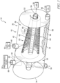
Fig. 3 is a diagrammatic perspective view of the air-oil separation system ofFig. 2 with portions broken away showing the air and oil mixture entering the inlet formed in the housing, the exhausted air exiting an air outlet formed in the housing, the separated oil exiting an oil outlet formed in the housing, a pressurized fluid entering a pressure inlet formed in the housing, and a pressurized fluid exiting a pressure outlet formed in the housing, the pressure inlet and the pressure outlet configured to guide the pressurized fluid towards an impellor for rotation thereof; -
Fig. 4 is a diagrammatic view of the process by which the air-oil separation system ofFig. 2 separates the air and oil mixture, the process includes a pump configured to draw the air and oil mixture away from the engine sump and into the air-oil separation system coupled with an oil tank, the air-oil separation system is configured to separate the air and oil mixture and direct the oil into the oil tank and the air out of the separation unit so that it may be exhausted to atmosphere; -
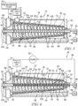
Fig. 5 is a diagrammatic cross-sectional view of the air-oil separation system ofFig. 2 ; and -
Fig. 6 is a diagrammatic cross-sectional view of the air-oil separation system adapted for use in the gas turbine engine ofFig. 1 showing the separation unit further including a metal form core formed therein and a pressurized fluid source configured to direct exhausted air from the air outlet of the housing towards an air pump configured to increase the pressure of the exhausted air and guide the pressurized, exhausted air towards a pressure inlet formed in the housing to drive an impellor in communication with the air-oil separation system. - For the purposes of promoting an understanding of the principles of the disclosure, reference will now be made to a number of illustrative embodiments illustrated in the drawings and specific language will be used to describe the same.
- An air-
oil separation system 12 in accordance with the present disclosure is adapted for use in agas turbine engine 10 as shown and suggested inFigs. 1-6 . Thegas turbine engine 10 includes afan 13, acompressor 15, acombustor 17, and aturbine 19 as shown inFig. 1 . Thefan 13 generates thrust for propelling an aircraft. Thecompressor 15 compresses and delivers air to thecombustor 17. Thecombustor 17 mixes fuel with the compressed air received from thecompressor 15 and ignites the fuel. The hot, high-pressure gases from the burning fuel are directed into theturbine 19 where theturbine 19 extracts work from the gases to drive thecompressor 15 and thefan 13. In other embodiments, thegas turbine engine 10 may include a shaft, turboprop, or gearbox in place of thefan 13. - The air-
oil separation system 12 is positioned within thegas turbine engine 10, as shown inFig. 1 , and may be coupled fluidly to anoil tank 16 located within theengine 10. The air-oil separation system 12 is configured to separate an air andoil mixture 14 such that the air and oil exit the air-oil separation system 12 distinct from each other. Illustratively, the air exits thesystem 12 as anexhausted air flow 26 and the oil exits thesystem 12 as a collectedoil flow 28. Theexhausted air flow 26 may be used to propel a device coupled to thegas turbine engine 10 and/or thesystem 12 itself. The collectedoil flow 28 may be returned to theoil tank 16 for re-use in theengine 10. - The air-
oil separation system 12 includes ahousing 18, aseparation unit 20, and arotation drive 22 as shown inFigs. 2 ,3 ,5, and 6 . Thehousing 18 is configured to contain theseparation unit 20 and therotation drive 22 therein. Theseparation unit 20 is positioned within thehousing 18 and is configured to receive the air andoil mixture 14 as shown inFigs. 3 ,5, and 6 . The rotation drive 22 is configured to rotate theseparation unit 20 using a source ofpressurized fluid 24 as suggested inFigs. 3 ,5, and 6 . As such, theseparation unit 20 and the rotation drive 22 cooperate to separate the oil from the air of the air andoil mixture 14 and direct each out of the air-oil separation system 12 independent of the other. Illustratively, theexhausted air flow 26 contains little to no remnants of oil from the air andoil mixture 14, and the collectedoil flow 28 contains little to no air from the air andoil mixture 14. - The
housing 18 includes anouter wall 30, afirst end wall 32, asecond end wall 34, and adivider plate 36 as shown inFigs. 2 ,3 ,5, and 6 . Theouter wall 30 extends circumferentially around theseparation unit 20 and the rotation drive 22 and cooperates with thefirst end wall 32 and thesecond end wall 34 to define aninterior region 38 therein. Thefirst end wall 32 extends perpendicularly to anaxis 40 and couples to theouter wall 30. Thesecond end wall 34 extends perpendicular to theaxis 40 and couples to theouter wall 30. Thefirst wall 32 is radially spaced apart from thesecond wall 34 and bothwalls outer wall 30 to define theinterior region 38. - The
outer wall 30 is formed to include anupper portion 42 and alower portion 44 as shown inFigs. 2 ,3 ,5, and 6 . Theupper portion 42 extends axially between thefirst end wall 32 and thesecond end wall 34 and is formed to include aninlet 48 configured to receive the air andoil mixture 14, illustratively. Thelower portion 44 extends axially between thefirst end wall 32 and thesecond end wall 34. Theinlet 48 extends radially away from theupper portion 42 of theouter wall 30. Theinlet 48 is formed to receive the air andoil mixture 14 collected in anengine sump 50 and guide the air andoil mixture 14 into theinterior region 38 of the air-oil separation system 12, as shown inFig. 4 . Illustratively, the air andoil mixture 14 flows from theengine sump 50 to apump 52 configured to direct the air andoil mixture 14 into the air-oil separation system 12 through theinlet 48. - The
first end wall 32 is formed to include anair outlet 54 and anoil outlet 56 as shown inFigs. 2 ,3 ,5, and 6 . Theair outlet 54 axially extends from thefirst end wall 32 and is aligned along theaxis 40. Theoil outlet 56 axially extends from thefirst end wall 32 and is radially spaced apart from theair outlet 54 relative to theaxis 40. - The
air outlet 54 is configured to guide the stream ofexhausted air flow 26 out of theinterior region 38 following separation of the air andoil mixture 14, as shown inFigs. 3 ,5, and 6 . Theexhausted air flow 26 is, illustratively, sucked from the air-oil separation system 12 and may be used for beneficial energy capture to propel a device requiring rotation to function, as suggested inFig. 5 . In some embodiments, the air is exhausted to ambient environment surrounding thesystem 12. - The
oil outlet 56 is configured to guide the collectedoil flow 28 out of theinterior region 38 following separation of the air andoil mixture 14 as shown inFigs. 3 ,5, and 6 . Illustratively, prior to exiting the air-oil separation system 12, any gaseous oil in the collectedoil flow 28 is congealed into a liquid state from the gaseous state. The collectedoil flow 28 may be guided out of the air-oil separation system 12 into theoil tank 16. - The
divider plate 36 is located between thefirst end wall 32 and thesecond end wall 34 and cooperates with thesecond end wall 34 to form adrive chamber 60, as shown inFigs. 2 ,3 ,5, and 6 . Thedrive chamber 60 is configured to receive a pressurized fluid and guide the pressurized fluid through thedrive chamber 60. - The
separation unit 20 includes an air-separation shaft 62 and an oil-separation rotor 64 as shown inFigs. 2 ,3 ,5, and 6 . The air-separation shaft 62 extends along theaxis 40 between thefirst end wall 32 and thesecond end wall 34. The air-separation shaft 62 is configured to receive residual air from the air andoil mixture 14, form theexhausted air flow 26, and guide theexhausted air flow 26 out from theinterior region 38 through theair outlet 54 formed in thefirst end wall 32. The air-separation shaft 62 is configured to rotate about theaxis 40. The oil-separation rotor 64 extends between thedivider plate 36 and thefirst end wall 32. The oil-separation rotor 64 is formed to receive the air andoil mixture 14 through theinlet 48 formed in theouter wall 30 of thehousing 18. Illustratively, the oil-separation rotor 64 is coupled to the air-separation shaft 62 and is configured to rotate therewith about theaxis 40. - The air-
separation shaft 62 includes abody 66 defining an air passage therein as shown inFigs. 2 ,3 ,5, and 6 . Thebody 66 extends along theaxis 40 between thefirst end wall 32 and thesecond end wall 34 and is further formed to include a plurality ofholes 68 therein. The plurality ofholes 68 extend radially through thebody 66 and axially along thebody 66 of the air-separation shaft 62. In some embodiments, the plurality ofholes 68 may be formed as clusters spaced apart from each other or any other formation known in the art. Illustratively, the plurality ofholes 68 are sized to allow air-sized molecules to enter thebody 66 of the air-separation shaft 62 and to block the oil of the air andoil mixture 14 from entering thebody 66. As such, only or substantially only air from the air andoil mixture 14 enters thebody 66 of the air-separation shaft 62 to be guided therethrough to theair outlet 54 formed in thefirst end wall 32. Illustratively, the air-separation shaft 62 rotates about theaxis 40 upon actuation of the air-oil separation system 12. - The oil-
separation rotor 64 includes anouter band 74, ametal foam core 72, and aninner band 70. Theouter band 74 is coupled to themetal foam core 72 and extends between thefirst end wall 32 and thesecond end wall 34. Themetal foam core 72 is positioned radially between theinner band 70 and theouter band 74 and extends between thefirst end wall 32 and thesecond end wall 34. Theinner band 70 extends between thefirst end wall 32 and thesecond end wall 34. Collectively, theouter band 74, themetal foam core 72, and theinner band 70 cooperate to receive the air andoil mixture 14. Theouter band 74, themetal foam core 72, and theinner band 70 further cooperate with the air-separation shaft 62 to separate the air and oil of the air andoil mixture 14. - The
outer band 74 is formed to include a plurality ofapertures 76 that extend radially therethrough and is configured to receive the air andoil mixture 14 through theinlet 48 formed in theouter wall 30 as shown inFigs. 2 ,3 ,5, and 6 . Illustratively, theouter band 74 is formed from a metallic material. Further, the plurality ofapertures 76 are sized to allow the air andoil mixture 14 to pass through theseparation unit 20. As such, theouter band 74 rotates with the air-oil separation system 12 upon actuation and is further configured to guide the air andoil mixture 14 between theinlet 48 and themetal foam core 72. - The
metal foam core 72 is configured to receive the air andoil mixture 14 from theouter band 74. Themetal foam core 72 is configured to act as a filter and permit air from the air andoil mixture 14 to pass through to theinner band 70. Themetal foam core 72 may be formed from any style foam metal. For example, themetal foam core 72 may be formed from, but is not limited to, RETIMET®. Themetal foam core 72 is configured to filter out some or all of the oil from the air andoil mixture 14. Illustratively, themetal foam core 72 is sized to allow air to pass freely through. Yet, oil may remain in the air andoil mixture 14. To further separate the remaining air andoil mixture 14, the remaining oil andair mixture 14 is guided to theinner band 70 after passing through themetal foam core 72. - The
inner band 70 is formed to include a plurality ofapertures 78 that extend radially therethrough. Theinner band 70 is configured to receive the remaining air andoil mixture 14 from themetal foam core 72. Further, the plurality ofapertures 78 are sized to allow the remaining air andoil mixture 14 to enter aninner zone 80 of theseparation unit 20. As such, theinner band 70 rotates upon actuation of the air-oil separation system 12. Illustratively, theouter band 74, themetal foam core 72, and theinner band 70 forming the oil-separation rotor 64 rotate together about theaxis 40. As such, the air andoil mixture 14 rotates about theaxis 40 and the air-separation shaft 62 upon entering theinner zone 80 of theseparation unit 20. - The rotation drive 22 includes at least one of an impeller and/or an electric motor (not shown) and a pressurized
fluid source 84 in communication with the impeller as suggested inFigs. 5 and 6 . The rotation drive 22 is configured to provide rotational energy to the air-oil separation system 12. The rotation drive 22 is coupled to the air-separation shaft 62 at thesecond end wall 34 and configured to rotate therewith upon actuation of thesystem 12. The pressurizedfluid source 84 is in communication with the impeller and configured to provide rotational energy thereto to rotate the air-separation shaft 62 coupled to the impeller. The impeller and the pressurizedfluid source 84 cooperate to achieve rotation of theseparation unit 20 about theaxis 40. - The pressurized
fluid source 84 is configured to provide thepressurized fluid 24 and direct the fluid 24 towards apressurized fluid inlet 88 positioned between thefirst end wall 32 and thedivider plate 36 and formed in theupper portion 42 of theouter wall 30, as suggested inFigs. 5 and 6 . Illustratively, the pressurizedfluid source 84 is the air-oil separation system 12 as shown inFig. 6 . In some embodiments, the pressurizedfluid source 84 is thecompressor 15 configured to provide pressurized bleed air therefrom. In other embodiments, the pressurizedfluid source 84 is the oil tank/oil source 16 configured to provide pressurized oil. - In the illustrative embodiment, air is separated from the air and
oil mixture 14 and guided through the air-separation shaft 62 until exiting thesystem 12 at theair outlet 54 formed in thefirst end wall 32 of thehousing 18. Aconduit 90 and apump 92 are further included in the pressurizedfluid source 84, and theconduit 90 is coupled to theair outlet 54 to guide the air from theair outlet 54 to thepressurized fluid inlet 88. Theconduit 90 is formed to extend between and couple to theair outlet 54 and thepressurized fluid inlet 88 and direct theexhausted air flow 26 towards thepump 92 coupled thereto. Thepump 92 is positioned such that theconduit 90 extends between theair outlet 54 and thepump 92 to provide theexhausted air flow 26 to thepump 92. - The
pump 92 is configured to increase the pressure of theexhausted air flow 26 such that the air is pressurized and pump thepressurized air 24 towards thepressurized fluid inlet 88. Theconduit 90 is further formed to extend between and couple to thepump 92 and thepressurized fluid inlet 88 and direct thepressurized air 24 towards theinlet 88. As thepressurized air 24 passes through theinlet 88, it enters thedrive chamber 60 and is guided therethrough to apressurized fluid outlet 94 located between thefirst end wall 32 and thedivider plate 36 and formed in thelower portion 44 of theouter wall 30. - Upon passing through the
drive chamber 60, thepressurized air 24 interacts with the air-separation shaft 62 coupled to the impeller positioned therein. The impeller is formed to rotate about theaxis 40 in response to thepressurized air 24, thereby rotating the air-separation shaft 62 therewith. Illustratively, the impeller and thepressurized air 24 cooperate to generate rotation of theseparation unit 20 and initiate the separation of the air-oil mixture 14 therein. - To begin the separation process, the
pressurized fluid 24 is guided into thedrive chamber 60, as discussed above, and rotates the impeller located therein and coupled to the air-separation shaft 62 as shown inFigs. 5 and 6 . As discussed above, the air-separation shaft 62 extends between thesecond end wall 34 and thefirst end wall 32 and is coupled to the oil-separation rotor 64 for rotation therewith. As such, upon rotation of the impeller about theaxis 40, the air-separation shaft 62 and the oil-separation rotor 64 rotate about theaxis 40.Such components oil mixture 14 guided therein following actuation of thesystem 12. - Upon initiation of rotation, the scavenged air and
oil mixture 14 is directed into theinterior region 38 of thehousing 18 through theinlet 48 from the bearing chambers (not shown). Theinlet 48 guides the air andoil mixture 14 towards theouter band 74 and through the plurality ofapertures 76 formed therein. Theapertures 76 are sized to allow both oil and air to pass through theouter band 74. - The
metal foam core 72 is configured to act as an additional filtration system and separates air-sized molecules and oil-sized molecules as the oil andair mixture 14 passes therethrough. Illustratively, the composition of themetal foam core 72 is configured to trap oil-sized molecules while allowing air-sized molecules to pass through. After passing through themetal foam core 72 the remainingmixture 14 may still include a combination of air and oil. Theinner band 70 is configured to provide additional separation of the air and oil. - As mentioned above, the
inner band 70 is formed to include a plurality ofapertures 78 sized to allow oil from the remainingmixture 14 to pass through and permeate the surface of theinner band 70. Such separation is accomplished by the rotation of theinner band 70 about theaxis 40 and the difference in density between air-molecules and oil-molecules. Since the oil-molecules have a greater density, they will be guided to the surface of theinner band 70 due to the rotation of theseparation unit 20, and thereby, provide an additional level of filtration. - Upon separation from the oil molecules, air molecules from the
mixture 14 may remain in theinterior region 38. The hollow air-separation shaft 62 is configured to remove the remaining air molecules through the air-sized plurality ofholes 68 formed therein. The air molecules are guided through theshaft 62 towards theair outlet 54 due to a vacuum mechanism in communication with theshaft 62. The air molecules are then expelled from theseparation unit 20 through theair outlet 54. - The remaining
oil 96 is collected in anoil collection section 98 located within thehousing 18. While in theoil collection section 98, the oil may re-congeal into a liquid state from the gaseous state. Illustratively, theoil collection section 98 is defined by thelower portion 44 of theouter wall 30, thedivider plate 36, thefirst end wall 32, and theoil outlet 56. The remainingoil 96 may be guided through theoil outlet 56 to theoil tank 16 and stored therein. - In some embodiments, the
oil outlet 56 may be expanded in size and/or reproduced such that there aremultiple oil outlets 56. An increase in the size and/or number of oil outlet(s) 56 may increase the capacity of oil the air-oil separator 12 may receive from the bearing chambers. - In some embodiments, the air-
separation shaft 62 further includes ametal foam core 100 positioned within thebody 66 as shown inFigs. 6 . Themetal foam core 100 is configured to act as an additional filter and permit air from the air andoil mixture 14 to pass through to theair outlet 54. Themetal foam core 100 may be formed from any style foam metal. For example, themetal foam core 100 may be formed from, but is not limited to, RETIMET®. As such, themetal foam core 100 may be sized to filter out oil remnants from the air located in the air-separation shaft 62. Themetal foam core 100 discourages oil from entering theshaft 62 and exiting from theair outlet 54. Illustratively, the foam structure of themetal foam core 100 of theshaft 62 is sized such that oil molecules are blocked from passing through themetal foam core 100 but air molecules are free to move therein. Theshaft 62 cooperates with themetal foam core 100 to trap air molecules within the shaft while allowing any oil molecules that enter theshaft 62 to pass through. - In other embodiments, the air-
separation shaft 62 further includes aplug 102 as shown inFigs. 5 and 6 . Theplug 102 is located within theshaft 62 and extends between and slightly beyond thesecond end wall 34 and thedivider plate 36. Theplug 102 is sized such that it blocks the air andoil mixture 14 from moving between theinterior region 38 and thedrive chamber 60 and guides the fluid within theshaft 62 towards theoil outlet 56. - In further embodiments, the air-
separation shaft 62 includes themetal foam core 100 and theplug 102 as shown inFig. 6 . Theplug 102 and themetal foam core 100 cooperate such that only air molecules exit theshaft 62 at theair outlet 54. - In additional embodiments, the oil-
separation rotor 64 further includes aspiral guide rail 104 as shown inFigs. 2 ,3 ,5, and 6 . Thespiral guide rail 104 is coupled to theinner band 70 and configured to guide the oil molecules of the air andoil mixture 14 into the plurality ofapertures 78 formed within theinner band 70. Due to the rotation of the air-oil separator 12, the air andoil mixture 14 is separated based on density such that the oil (having a higher density) is forced outwardly towards theinner band 70 and interacts with theguide rail 104. Theguide rail 104 is shaped to direct the oil towards theinner band 70 and cooperate with the plurality ofapertures 78 to allow oil to permeate the surface of theinner band 70 and collect in theoil collection section 98 prior to expulsion from thehousing 18 of the air-oil separation system 12. Theguide rail 104 extends radially inward toward theaxis 40 from theinner band 70. In some embodiments, an electric motor is coupled to the air-separation shaft 62 and located outside of thedrive chamber 60 such that the impeller, and thepressurized air 24 may be omitted. - The air-
oil separator 12 of the present application may be sufficiently efficient to use on thegas turbine engine 10 without using an engine breather system (not shown). The air-oil separator 12 of the present disclosure may provide cost reductions for thegas turbine engine 10 and reduce the total engine set value. The air-oil separator 12 is configured to remove the air from the air andoil mixture 14 and the oil from the remaining air andoil mixture 14. The air-oil separator 12 is configured to generate rotational motion about theaxis 40 from the incoming air andoil mixture 14 originating from/collected in the bearing chambers. In doing so, the air-oil separator 12 is configured to generate the correct amount of centrifugal forces to extract the less dense air from the more dense oil of the air andoil mixture 14. The air-oil separator 12 may also decrease the overall weight of thegas turbine engine 10. - The
gas turbine engine 10 having the air-oil separator 12 of the present application may be configured to eliminate excessive intake of air into the bearing chambers. A carbon seal style sealing mechanism (not shown) may be implemented with an un-vented bearing chamber such that the amount of air drawn across the seal(s) to maintain leak-free operation may be reduced. This may reduce the air draw into the bearing chamber such that the amount of air to be removed from the air andgas mixture 14 is lessened. - To extract the air from the air and
gas mixture 14, a multi-stage separation within a single unit, such as the air-oil separator 12, may be used. The air-oil separator 12 may be positioned within/coupled to theoil tank 16 and/or in-line with at least one scavenge oil line (not shown). The air-oil separator 12 may contain a semi-dense, metal foam material that is configured to eliminate the dense/heavy oil molecules from the less dense/lighter air molecules of the air andoil mixture 14. The air-oil separator 12 may contain metal foam material that is configured to generate a cyclonic motion to extract the oil from the oil andair mixture 14. The air-oil separator 12 may be coupled to an upper section of theoil tank 16 or utilized as a stand-alone device within thegas turbine engine 10. - The air-
oil separator 12 may generate a high speed rotation to propel theseparation unit 20 positioned therein by receiving pressurized fluid 24 from the main oil pump (not shown). Theseparation unit 20 may be formed to receive the air and oil mixture/aerated scavenge oil 14 from the bearing chambers and guide it into theinner zone 80 of theseparation unit 20 wherein the air-separation shaft 62 is located. Further, theseparation unit 20 may be shaped as a cone. - Upon entering the
inner zone 80, the air andoil mixture 14 may rotate about theshaft 62 of the air-oil separator 12 and contact thespiral guide rail 104 of theinner band 70. Theinner band 70 may be further formed to include a plurality of diffusion holes 78 sized such that oil from the air andoil mixture 14 may permeate the surface of theinner band 70. The air-oil separator 12 may then guide the oil through theouter band 74 formed from the metal foam and into theoil collection section 98 until guided back to theoil tank 16 through theoil outlet 56. The remaining air from the air andoil mixture 14 may stay withininner zone 80. To remove the remaining air, theshaft 62 may be formed to have the perforatedholes 68 sized to allow only air-sized particles to enter theinterior region 38 of theshaft 62. Further, suction may be used to remove the air from within theinterior region 38 of theshaft 62 through theair outlet 54. The air from theair outlet 54 may be used for beneficial energy capture to propel any device that may use rotation to function. The air may also be pressurized after exiting theshaft 62 and then guided into thepressurized fluid inlet 48 to assist in propulsion of thegas turbine engine 10 and/or a device coupled thereto. - In some embodiments, the
shaft 62 may include thebody 66 formed from foam metal to discourage any oil that happened to enter theshaft 62 from exiting theshaft 62 through theair outlet 54. In other embodiments, theoil outlet 56 may be expanded in size and/or the air-oil separator 12 may be formed to include a plurality ofoil outlets 56. Increasing the size and/or number of the oil outlet(s) 56 may increase the capacity of oil the air-oil separator 12 receives from the bearing chambers. The air-oil separator 12 may reduce production cost, reduce the weight of thegas turbine engine 10, and decrease the environmental effects of theengine 10. - While the disclosure has been illustrated and described in detail in the foregoing drawings and description, the same is to be considered as exemplary and not restrictive in character, it being understood that only illustrative embodiments thereof have been shown and described and that all changes and modifications that come within the scope of the amended claims are desired to be protected.
Claims (10)
- An air-oil separation system (12) for a gas turbine engine (10), the air-oil separation system (12) comprising:a housing (18) that extends circumferentially around an axis (40) to define an interior chamber (38) of the housing (18) and including a first end wall (32), a second end wall (34), and a divider plate (36) arranged between the first end wall (32) and the second end wall (34), the divider plate (36) cooperating with the second end wall (34) to form a drive chamber (60) therebetween, the housing (18) formed to include an inlet (48) configured to receive a mixture of air and oil (14), an oil outlet (56) configured to conduct oil substantially free of air to exit the housing (18), and an air outlet (54) configured to conduct air substantially free of oil to exit the housing (18), the inlet (48) formed to receive the mixture of air and oil (14) collected in an engine sump (50) and guide the mixture of air and oil (14) into the interior region (38), the mixture of air and oil (14) flowing from the engine sump (50) to a pump (52) configured to direct the mixture of air and oil (14) into the air-oil separation system (12) through the inlet (48),an air-separation shaft (62) located in the interior chamber (38) of the housing (18) and extending between the first end wall (32) and the second end wall (34), the air-separation shaft (63) configured to rotate about the axis (40) relative to the housing (18) during use of the air-oil separation system (12), the air-separation shaft (62) formed to include an air passage that extends axially through the air-separation shaft (62) and a plurality of air holes (68) that extend radially through the air-separation shaft (62) and open into the air passage, and the air passage being in fluid communication with the air outlet (54) so that air located in the interior chamber (38) is separated from oil and conducted through the plurality of air holes (68) into the air passage and out of the air outlet (54) during operation of the air-oil separation system (12),an oil-separation rotor (64) located in the interior chamber (38) of the housing (18), extending between the divider plate (36) and the first end wall (32), and arranged circumferentially around the air-separation shaft (62), the oil-separation rotor (64) being rotatably coupled with the air-separation shaft (62) for rotation about the axis (40) relative to the housing (18) during use of the air-oil separation system (12), the oil-separation rotor (64) formed to include a plurality of oil holes (76, 78) that extend radially through the oil-separation rotor (64) to cause oil located in the interior chamber (38) to be separated from air and conducted radially outward through the plurality of oil holes (76, 78) toward the housing (18) and out of the oil outlet (56) during operation of the air-oil separation system (12), andan impeller rotatably coupled with the air-separation shaft (62) and configured to drive rotation of the air-separation shaft (62) and the oil-separation rotor (64) about the axis (40).
- The air-oil separation system (12) of claim 1, further comprising a conduit (90) fluidly coupled with the air outlet (54) and configured to direct air received by the air outlet (54) from the air-separation shaft (62) toward the impeller.
- The air-oil separation system (12) of any one of claims 1 to 2, wherein the oil-separation rotor (64) includes an inner band (70) arranged circumferentially about the axis (40), an outer band (74) arranged circumferentially about the inner band (70), and a metallic foam material (72) located radially between the inner band (70) and the outer band (74).
- The air-oil separation system (12) of claim 3, wherein the oil-separation rotor (64) further includes a spiral guide rail (104) coupled to the inner band (70) to locate the inner band (70) radially between the spiral guide rail (104) and the metallic foam material (72), and wherein the spiral guide rail (104) is configured to guide oil molecules of the mixture of air and oil (14) into the plurality of apertures (78) formed within the inner band (70).
- The air-oil separation system (12) of any one of claims 1 to 4, wherein the air-separation shaft (62) includes a cylindrical body (66) and a metallic foam material (100) located radially within the body (66) in the air passage.
- The air-oil separation system (12) of any one of claims 1 to 5, further comprising a rotation drive (22) coupled with the air-separation shaft (62) and configured to rotate the air-separation shaft (62) about the axis (40).
- The air-oil separation system (12) of claim 6, wherein the rotation drive (22) includes a bladed rotor rotatably coupled with the air-separation shaft (62).
- The air-oil separation system (12) of claim 7, wherein the rotation drive (22) further includes a pressurized fluid source (84) configured to supply pressurized fluid (24) to the bladed rotor.
- The air-oil separation system (12) of claim 6, wherein the rotation drive (22) includes an electric motor.
- A method comprising:providing an air oil separation system (12) according to any of the preceding claims wherein the air separation shaft and the oil-separation rotor are coupled to provide a separation unit (20) located in the interior region (38) of the housing (18);the divider plate cooperating with the second end wall (34) to form a drive chamber (60) therebetween and comprising the impeller;rotating the separation unit (20) about an axis (40) relative to the housing (18), via the impeller, andsupplying a mixture of air and oil (14) to the interior region (38) of the housing (18) through the inlet (48) to cause the mixture of air and oil (14) to interact with the rotating separation unit (20) to separate the air from the oil.
Applications Claiming Priority (1)
| Application Number | Priority Date | Filing Date | Title |
|---|---|---|---|
| US16/291,681 US11255265B2 (en) | 2019-03-04 | 2019-03-04 | Air-oil separation system for gas turbine engine |
Publications (2)
| Publication Number | Publication Date |
|---|---|
| EP3718638A1 EP3718638A1 (en) | 2020-10-07 |
| EP3718638B1 true EP3718638B1 (en) | 2023-06-07 |
Family
ID=69770437
Family Applications (1)
| Application Number | Title | Priority Date | Filing Date |
|---|---|---|---|
| EP20160610.0A Active EP3718638B1 (en) | 2019-03-04 | 2020-03-03 | Air-oil separation system for gas turbine engine |
Country Status (3)
| Country | Link |
|---|---|
| US (1) | US11255265B2 (en) |
| EP (1) | EP3718638B1 (en) |
| CA (1) | CA3068979A1 (en) |
Families Citing this family (7)
| Publication number | Priority date | Publication date | Assignee | Title |
|---|---|---|---|---|
| US11511876B2 (en) * | 2018-12-03 | 2022-11-29 | Textron Innovations Inc. | Variable porosity load-bearing and heat-dissipating aircraft structures |
| CN113694567B (en) * | 2021-09-15 | 2022-10-28 | 中国石油大学(华东) | Two-stage gas-liquid mixing conical spiral field separation device |
| CN117072653A (en) * | 2022-05-09 | 2023-11-17 | 中国航发商用航空发动机有限责任公司 | Gas turbine engine, oil ventilation system and oil system ventilation method |
| US12253001B2 (en) | 2022-11-28 | 2025-03-18 | Pratt & Whitney Canada Corp. | Static de-aerator and lubricant system |
| US12215627B2 (en) * | 2023-02-08 | 2025-02-04 | General Electric Company | Separators for use with gas turbine engines |
| US12031463B1 (en) * | 2023-05-31 | 2024-07-09 | Deltahawk Engines, Inc. | Separator for liquid and gas |
| US20250382896A1 (en) * | 2024-06-12 | 2025-12-18 | Rtx Corporation | Hydraulically driven de-oiler for gas turbine engines |
Citations (1)
| Publication number | Priority date | Publication date | Assignee | Title |
|---|---|---|---|---|
| US20110180051A1 (en) * | 2010-01-27 | 2011-07-28 | Cummins Filtration Ip Inc. | Crankcase Ventilation Inside-Out Flow Rotating Coalescer |
Family Cites Families (23)
| Publication number | Priority date | Publication date | Assignee | Title |
|---|---|---|---|---|
| DE3137947C2 (en) | 1980-09-26 | 1983-10-27 | Rolls-Royce Ltd., London | Lubricating oil system for gas turbine engines suitable for any flight maneuver |
| FR2742804B1 (en) | 1995-12-20 | 1998-01-16 | Snecma | LUBRICATION ENCLOSURE ROTOR ROTOR |
| JP4052827B2 (en) | 2001-11-07 | 2008-02-27 | 本田技研工業株式会社 | Centrifugal gas-liquid separator |
| US6877950B2 (en) | 2001-11-29 | 2005-04-12 | Pratt & Whitney Canada Corp. | Method and device for minimizing oil consumption in a gas turbine engine |
| GB0206243D0 (en) | 2002-03-16 | 2002-05-01 | Rolls Royce Plc | An air/oil separator |
| SE525091C2 (en) * | 2003-04-16 | 2004-11-30 | Alfa Laval Corp Ab | An apparatus for purifying a gas |
| US7063734B2 (en) | 2004-03-23 | 2006-06-20 | Pratt & Whitney Canada Corp. | Air/oil separation system and method |
| EP1933077B1 (en) | 2006-12-12 | 2010-05-05 | Techspace aero | Method and system for lubricating a turbomachine |
| US7833303B1 (en) * | 2007-08-08 | 2010-11-16 | Charles George Higgins | Sifting apparatus with filter rotation and particle collection |
| US8245818B2 (en) | 2007-10-23 | 2012-08-21 | Pratt & Whitney Canada Corp. | Gas turbine oil scavenging system |
| US8292034B2 (en) | 2007-11-28 | 2012-10-23 | General Electric Company | Air-oil separator |
| FR2925594B1 (en) * | 2007-12-20 | 2014-05-16 | Hispano Suiza Sa | SYSTEM FOR CONTROLLING A TURBOMACHINE |
| US8181746B2 (en) | 2008-09-18 | 2012-05-22 | United Technologies Corporation | Continuous supply fluid reservoir |
| US7867310B2 (en) | 2009-01-29 | 2011-01-11 | General Electric Company | Method and apparatus for separating air and oil |
| US8601785B2 (en) | 2010-06-23 | 2013-12-10 | Pratt & Whitney Canada Corp. | Oil supply system with main pump deaeration |
| GB201117662D0 (en) | 2011-10-13 | 2011-11-23 | Rolls Royce Plc | Fluid separator |
| US9097180B2 (en) | 2013-01-28 | 2015-08-04 | General Electric Company | Apparatus and method for reducing oil mist ingestion in a heavy duty gas turbine engine |
| US9732707B1 (en) * | 2013-12-09 | 2017-08-15 | High Output Technology, LLC | Vent for engine crankcases |
| US10060289B2 (en) | 2014-07-29 | 2018-08-28 | United Technologies Corporation | Geared gas turbine engine with oil deaerator and air removal |
| US9765644B2 (en) | 2015-01-20 | 2017-09-19 | United Technologies Corporation | Deoiler debris baffle |
| EP3315182A1 (en) | 2016-10-31 | 2018-05-02 | Pratt & Whitney Canada Corp. | Centrifugal separator |
| FR3064304B1 (en) | 2017-03-21 | 2019-03-22 | Safran Helicopter Engines | CENTRIFUGAL DEGRAYER OF TURBOMACHINE |
| FR3090394B1 (en) | 2018-12-19 | 2021-12-24 | Safran Trans Systems | Device for separating an air/oil mixture |
-
2019
- 2019-03-04 US US16/291,681 patent/US11255265B2/en active Active
-
2020
- 2020-01-20 CA CA3068979A patent/CA3068979A1/en not_active Abandoned
- 2020-03-03 EP EP20160610.0A patent/EP3718638B1/en active Active
Patent Citations (1)
| Publication number | Priority date | Publication date | Assignee | Title |
|---|---|---|---|---|
| US20110180051A1 (en) * | 2010-01-27 | 2011-07-28 | Cummins Filtration Ip Inc. | Crankcase Ventilation Inside-Out Flow Rotating Coalescer |
Also Published As
| Publication number | Publication date |
|---|---|
| US20200284163A1 (en) | 2020-09-10 |
| EP3718638A1 (en) | 2020-10-07 |
| US11255265B2 (en) | 2022-02-22 |
| CA3068979A1 (en) | 2020-09-04 |
Similar Documents
| Publication | Publication Date | Title |
|---|---|---|
| EP3718638B1 (en) | Air-oil separation system for gas turbine engine | |
| EP1582703B1 (en) | Gas turbine engine and method of separating oil from air in said gas turbine engine | |
| US9028576B2 (en) | Gearbox deoiler with pre-pressuring component | |
| CA2733072C (en) | Oil supply system with main pump deaeration | |
| US8657931B2 (en) | Gearbox deoiler with sychnronizer | |
| US3528241A (en) | Gas turbine engine lubricant sump vent and circulating system | |
| US20170096910A1 (en) | Turbine Engine Oil Reservoir with Deaerator | |
| CA2713802C (en) | Lubrication system with porous element | |
| US11110379B2 (en) | Device for separating an air/oil mixture | |
| US11181010B2 (en) | Aircraft engine and air-oil separator system therefore | |
| GB2540036B (en) | A de-oiler and a method of using the same | |
| US11549641B2 (en) | Double journal bearing impeller for active de-aerator | |
| US11162420B2 (en) | Gas turbine engine oil scavenging system and method | |
| US10392978B2 (en) | Filtering of a flow of gas/particles | |
| US20240175376A1 (en) | Static de-aerator and lubricant system | |
| US20250196037A1 (en) | Air-oil separator | |
| US12352209B1 (en) | Aircraft engine fluid separation system and method | |
| US12049850B1 (en) | Fan drive gear system gutter ejector system | |
| RU2530968C1 (en) | Oil system of aviation gas turbine engine |
Legal Events
| Date | Code | Title | Description |
|---|---|---|---|
| PUAI | Public reference made under article 153(3) epc to a published international application that has entered the european phase |
Free format text: ORIGINAL CODE: 0009012 |
|
| STAA | Information on the status of an ep patent application or granted ep patent |
Free format text: STATUS: THE APPLICATION HAS BEEN PUBLISHED |
|
| AK | Designated contracting states |
Kind code of ref document: A1 Designated state(s): AL AT BE BG CH CY CZ DE DK EE ES FI FR GB GR HR HU IE IS IT LI LT LU LV MC MK MT NL NO PL PT RO RS SE SI SK SM TR |
|
| AX | Request for extension of the european patent |
Extension state: BA ME |
|
| STAA | Information on the status of an ep patent application or granted ep patent |
Free format text: STATUS: REQUEST FOR EXAMINATION WAS MADE |
|
| 17P | Request for examination filed |
Effective date: 20210317 |
|
| RBV | Designated contracting states (corrected) |
Designated state(s): AL AT BE BG CH CY CZ DE DK EE ES FI FR GB GR HR HU IE IS IT LI LT LU LV MC MK MT NL NO PL PT RO RS SE SI SK SM TR |
|
| STAA | Information on the status of an ep patent application or granted ep patent |
Free format text: STATUS: EXAMINATION IS IN PROGRESS |
|
| 17Q | First examination report despatched |
Effective date: 20220317 |
|
| REG | Reference to a national code |
Ref country code: DE Ref legal event code: R079 Free format text: PREVIOUS MAIN CLASS: B04B0009060000 Ipc: F16N0039000000 Ref document number: 602020011473 Country of ref document: DE |
|
| GRAP | Despatch of communication of intention to grant a patent |
Free format text: ORIGINAL CODE: EPIDOSNIGR1 |
|
| STAA | Information on the status of an ep patent application or granted ep patent |
Free format text: STATUS: GRANT OF PATENT IS INTENDED |
|
| RIC1 | Information provided on ipc code assigned before grant |
Ipc: F01M 13/04 20060101ALN20230210BHEP Ipc: B04B 9/06 20060101ALI20230210BHEP Ipc: B04B 5/08 20060101ALI20230210BHEP Ipc: B04B 5/04 20060101ALI20230210BHEP Ipc: B04B 5/00 20060101ALI20230210BHEP Ipc: B04B 1/00 20060101ALI20230210BHEP Ipc: B01D 45/14 20060101ALI20230210BHEP Ipc: B01D 19/00 20060101ALI20230210BHEP Ipc: F02C 7/32 20060101ALI20230210BHEP Ipc: F02C 7/06 20060101ALI20230210BHEP Ipc: F01D 25/20 20060101ALI20230210BHEP Ipc: F01D 25/18 20060101ALI20230210BHEP Ipc: F16N 39/00 20060101AFI20230210BHEP |
|
| INTG | Intention to grant announced |
Effective date: 20230309 |
|
| GRAS | Grant fee paid |
Free format text: ORIGINAL CODE: EPIDOSNIGR3 |
|
| GRAA | (expected) grant |
Free format text: ORIGINAL CODE: 0009210 |
|
| STAA | Information on the status of an ep patent application or granted ep patent |
Free format text: STATUS: THE PATENT HAS BEEN GRANTED |
|
| AK | Designated contracting states |
Kind code of ref document: B1 Designated state(s): AL AT BE BG CH CY CZ DE DK EE ES FI FR GB GR HR HU IE IS IT LI LT LU LV MC MK MT NL NO PL PT RO RS SE SI SK SM TR |
|
| REG | Reference to a national code |
Ref country code: GB Ref legal event code: FG4D |
|
| REG | Reference to a national code |
Ref country code: CH Ref legal event code: EP Ref country code: AT Ref legal event code: REF Ref document number: 1576057 Country of ref document: AT Kind code of ref document: T Effective date: 20230615 |
|
| REG | Reference to a national code |
Ref country code: DE Ref legal event code: R096 Ref document number: 602020011473 Country of ref document: DE |
|
| P01 | Opt-out of the competence of the unified patent court (upc) registered |
Effective date: 20230528 |
|
| REG | Reference to a national code |
Ref country code: LT Ref legal event code: MG9D |
|
| REG | Reference to a national code |
Ref country code: NL Ref legal event code: MP Effective date: 20230607 |
|
| PG25 | Lapsed in a contracting state [announced via postgrant information from national office to epo] |
Ref country code: SE Free format text: LAPSE BECAUSE OF FAILURE TO SUBMIT A TRANSLATION OF THE DESCRIPTION OR TO PAY THE FEE WITHIN THE PRESCRIBED TIME-LIMIT Effective date: 20230607 Ref country code: NO Free format text: LAPSE BECAUSE OF FAILURE TO SUBMIT A TRANSLATION OF THE DESCRIPTION OR TO PAY THE FEE WITHIN THE PRESCRIBED TIME-LIMIT Effective date: 20230907 Ref country code: ES Free format text: LAPSE BECAUSE OF FAILURE TO SUBMIT A TRANSLATION OF THE DESCRIPTION OR TO PAY THE FEE WITHIN THE PRESCRIBED TIME-LIMIT Effective date: 20230607 |
|
| REG | Reference to a national code |
Ref country code: AT Ref legal event code: MK05 Ref document number: 1576057 Country of ref document: AT Kind code of ref document: T Effective date: 20230607 |
|
| PG25 | Lapsed in a contracting state [announced via postgrant information from national office to epo] |
Ref country code: RS Free format text: LAPSE BECAUSE OF FAILURE TO SUBMIT A TRANSLATION OF THE DESCRIPTION OR TO PAY THE FEE WITHIN THE PRESCRIBED TIME-LIMIT Effective date: 20230607 Ref country code: NL Free format text: LAPSE BECAUSE OF FAILURE TO SUBMIT A TRANSLATION OF THE DESCRIPTION OR TO PAY THE FEE WITHIN THE PRESCRIBED TIME-LIMIT Effective date: 20230607 Ref country code: LV Free format text: LAPSE BECAUSE OF FAILURE TO SUBMIT A TRANSLATION OF THE DESCRIPTION OR TO PAY THE FEE WITHIN THE PRESCRIBED TIME-LIMIT Effective date: 20230607 Ref country code: LT Free format text: LAPSE BECAUSE OF FAILURE TO SUBMIT A TRANSLATION OF THE DESCRIPTION OR TO PAY THE FEE WITHIN THE PRESCRIBED TIME-LIMIT Effective date: 20230607 Ref country code: HR Free format text: LAPSE BECAUSE OF FAILURE TO SUBMIT A TRANSLATION OF THE DESCRIPTION OR TO PAY THE FEE WITHIN THE PRESCRIBED TIME-LIMIT Effective date: 20230607 Ref country code: GR Free format text: LAPSE BECAUSE OF FAILURE TO SUBMIT A TRANSLATION OF THE DESCRIPTION OR TO PAY THE FEE WITHIN THE PRESCRIBED TIME-LIMIT Effective date: 20230908 |
|
| PG25 | Lapsed in a contracting state [announced via postgrant information from national office to epo] |
Ref country code: FI Free format text: LAPSE BECAUSE OF FAILURE TO SUBMIT A TRANSLATION OF THE DESCRIPTION OR TO PAY THE FEE WITHIN THE PRESCRIBED TIME-LIMIT Effective date: 20230607 |
|
| PG25 | Lapsed in a contracting state [announced via postgrant information from national office to epo] |
Ref country code: SK Free format text: LAPSE BECAUSE OF FAILURE TO SUBMIT A TRANSLATION OF THE DESCRIPTION OR TO PAY THE FEE WITHIN THE PRESCRIBED TIME-LIMIT Effective date: 20230607 |
|
| PG25 | Lapsed in a contracting state [announced via postgrant information from national office to epo] |
Ref country code: IS Free format text: LAPSE BECAUSE OF FAILURE TO SUBMIT A TRANSLATION OF THE DESCRIPTION OR TO PAY THE FEE WITHIN THE PRESCRIBED TIME-LIMIT Effective date: 20231007 |
|
| PG25 | Lapsed in a contracting state [announced via postgrant information from national office to epo] |
Ref country code: SM Free format text: LAPSE BECAUSE OF FAILURE TO SUBMIT A TRANSLATION OF THE DESCRIPTION OR TO PAY THE FEE WITHIN THE PRESCRIBED TIME-LIMIT Effective date: 20230607 Ref country code: SK Free format text: LAPSE BECAUSE OF FAILURE TO SUBMIT A TRANSLATION OF THE DESCRIPTION OR TO PAY THE FEE WITHIN THE PRESCRIBED TIME-LIMIT Effective date: 20230607 Ref country code: RO Free format text: LAPSE BECAUSE OF FAILURE TO SUBMIT A TRANSLATION OF THE DESCRIPTION OR TO PAY THE FEE WITHIN THE PRESCRIBED TIME-LIMIT Effective date: 20230607 Ref country code: PT Free format text: LAPSE BECAUSE OF FAILURE TO SUBMIT A TRANSLATION OF THE DESCRIPTION OR TO PAY THE FEE WITHIN THE PRESCRIBED TIME-LIMIT Effective date: 20231009 Ref country code: IS Free format text: LAPSE BECAUSE OF FAILURE TO SUBMIT A TRANSLATION OF THE DESCRIPTION OR TO PAY THE FEE WITHIN THE PRESCRIBED TIME-LIMIT Effective date: 20231007 Ref country code: EE Free format text: LAPSE BECAUSE OF FAILURE TO SUBMIT A TRANSLATION OF THE DESCRIPTION OR TO PAY THE FEE WITHIN THE PRESCRIBED TIME-LIMIT Effective date: 20230607 Ref country code: CZ Free format text: LAPSE BECAUSE OF FAILURE TO SUBMIT A TRANSLATION OF THE DESCRIPTION OR TO PAY THE FEE WITHIN THE PRESCRIBED TIME-LIMIT Effective date: 20230607 Ref country code: AT Free format text: LAPSE BECAUSE OF FAILURE TO SUBMIT A TRANSLATION OF THE DESCRIPTION OR TO PAY THE FEE WITHIN THE PRESCRIBED TIME-LIMIT Effective date: 20230607 |
|
| PG25 | Lapsed in a contracting state [announced via postgrant information from national office to epo] |
Ref country code: PL Free format text: LAPSE BECAUSE OF FAILURE TO SUBMIT A TRANSLATION OF THE DESCRIPTION OR TO PAY THE FEE WITHIN THE PRESCRIBED TIME-LIMIT Effective date: 20230607 |
|
| REG | Reference to a national code |
Ref country code: DE Ref legal event code: R097 Ref document number: 602020011473 Country of ref document: DE |
|
| PLBE | No opposition filed within time limit |
Free format text: ORIGINAL CODE: 0009261 |
|
| STAA | Information on the status of an ep patent application or granted ep patent |
Free format text: STATUS: NO OPPOSITION FILED WITHIN TIME LIMIT |
|
| PG25 | Lapsed in a contracting state [announced via postgrant information from national office to epo] |
Ref country code: DK Free format text: LAPSE BECAUSE OF FAILURE TO SUBMIT A TRANSLATION OF THE DESCRIPTION OR TO PAY THE FEE WITHIN THE PRESCRIBED TIME-LIMIT Effective date: 20230607 |
|
| PG25 | Lapsed in a contracting state [announced via postgrant information from national office to epo] |
Ref country code: SI Free format text: LAPSE BECAUSE OF FAILURE TO SUBMIT A TRANSLATION OF THE DESCRIPTION OR TO PAY THE FEE WITHIN THE PRESCRIBED TIME-LIMIT Effective date: 20230607 |
|
| 26N | No opposition filed |
Effective date: 20240308 |
|
| PG25 | Lapsed in a contracting state [announced via postgrant information from national office to epo] |
Ref country code: SI Free format text: LAPSE BECAUSE OF FAILURE TO SUBMIT A TRANSLATION OF THE DESCRIPTION OR TO PAY THE FEE WITHIN THE PRESCRIBED TIME-LIMIT Effective date: 20230607 Ref country code: IT Free format text: LAPSE BECAUSE OF FAILURE TO SUBMIT A TRANSLATION OF THE DESCRIPTION OR TO PAY THE FEE WITHIN THE PRESCRIBED TIME-LIMIT Effective date: 20230607 |
|
| REG | Reference to a national code |
Ref country code: DE Ref legal event code: R119 Ref document number: 602020011473 Country of ref document: DE |
|
| REG | Reference to a national code |
Ref country code: CH Ref legal event code: PL |
|
| PG25 | Lapsed in a contracting state [announced via postgrant information from national office to epo] |
Ref country code: BG Free format text: LAPSE BECAUSE OF FAILURE TO SUBMIT A TRANSLATION OF THE DESCRIPTION OR TO PAY THE FEE WITHIN THE PRESCRIBED TIME-LIMIT Effective date: 20230607 |
|
| PG25 | Lapsed in a contracting state [announced via postgrant information from national office to epo] |
Ref country code: LU Free format text: LAPSE BECAUSE OF NON-PAYMENT OF DUE FEES Effective date: 20240303 |
|
| PG25 | Lapsed in a contracting state [announced via postgrant information from national office to epo] |
Ref country code: MC Free format text: LAPSE BECAUSE OF FAILURE TO SUBMIT A TRANSLATION OF THE DESCRIPTION OR TO PAY THE FEE WITHIN THE PRESCRIBED TIME-LIMIT Effective date: 20230607 |
|
| GBPC | Gb: european patent ceased through non-payment of renewal fee |
Effective date: 20240303 |
|
| PG25 | Lapsed in a contracting state [announced via postgrant information from national office to epo] |
Ref country code: MC Free format text: LAPSE BECAUSE OF FAILURE TO SUBMIT A TRANSLATION OF THE DESCRIPTION OR TO PAY THE FEE WITHIN THE PRESCRIBED TIME-LIMIT Effective date: 20230607 Ref country code: BG Free format text: LAPSE BECAUSE OF FAILURE TO SUBMIT A TRANSLATION OF THE DESCRIPTION OR TO PAY THE FEE WITHIN THE PRESCRIBED TIME-LIMIT Effective date: 20230607 Ref country code: LU Free format text: LAPSE BECAUSE OF NON-PAYMENT OF DUE FEES Effective date: 20240303 |
|
| REG | Reference to a national code |
Ref country code: BE Ref legal event code: MM Effective date: 20240331 |
|
| PG25 | Lapsed in a contracting state [announced via postgrant information from national office to epo] |
Ref country code: DE Free format text: LAPSE BECAUSE OF NON-PAYMENT OF DUE FEES Effective date: 20241001 |
|
| PG25 | Lapsed in a contracting state [announced via postgrant information from national office to epo] |
Ref country code: BE Free format text: LAPSE BECAUSE OF NON-PAYMENT OF DUE FEES Effective date: 20240331 |
|
| PG25 | Lapsed in a contracting state [announced via postgrant information from national office to epo] |
Ref country code: GB Free format text: LAPSE BECAUSE OF NON-PAYMENT OF DUE FEES Effective date: 20240303 |
|
| PG25 | Lapsed in a contracting state [announced via postgrant information from national office to epo] |
Ref country code: IE Free format text: LAPSE BECAUSE OF NON-PAYMENT OF DUE FEES Effective date: 20240303 |
|
| PG25 | Lapsed in a contracting state [announced via postgrant information from national office to epo] |
Ref country code: IE Free format text: LAPSE BECAUSE OF NON-PAYMENT OF DUE FEES Effective date: 20240303 Ref country code: GB Free format text: LAPSE BECAUSE OF NON-PAYMENT OF DUE FEES Effective date: 20240303 Ref country code: DE Free format text: LAPSE BECAUSE OF NON-PAYMENT OF DUE FEES Effective date: 20241001 Ref country code: BE Free format text: LAPSE BECAUSE OF NON-PAYMENT OF DUE FEES Effective date: 20240331 Ref country code: CH Free format text: LAPSE BECAUSE OF NON-PAYMENT OF DUE FEES Effective date: 20240331 |
|
| PG25 | Lapsed in a contracting state [announced via postgrant information from national office to epo] |
Ref country code: CY Free format text: LAPSE BECAUSE OF FAILURE TO SUBMIT A TRANSLATION OF THE DESCRIPTION OR TO PAY THE FEE WITHIN THE PRESCRIBED TIME-LIMIT; INVALID AB INITIO Effective date: 20200303 |
|
| PG25 | Lapsed in a contracting state [announced via postgrant information from national office to epo] |
Ref country code: HU Free format text: LAPSE BECAUSE OF FAILURE TO SUBMIT A TRANSLATION OF THE DESCRIPTION OR TO PAY THE FEE WITHIN THE PRESCRIBED TIME-LIMIT; INVALID AB INITIO Effective date: 20200303 |
|
| PG25 | Lapsed in a contracting state [announced via postgrant information from national office to epo] |
Ref country code: TR Free format text: LAPSE BECAUSE OF FAILURE TO SUBMIT A TRANSLATION OF THE DESCRIPTION OR TO PAY THE FEE WITHIN THE PRESCRIBED TIME-LIMIT Effective date: 20230607 |
|
| PGFP | Annual fee paid to national office [announced via postgrant information from national office to epo] |
Ref country code: FR Payment date: 20260323 Year of fee payment: 7 |