EP3718465A1 - Medical instrument calibration - Google Patents
Medical instrument calibration Download PDFInfo
- Publication number
- EP3718465A1 EP3718465A1 EP20167943.8A EP20167943A EP3718465A1 EP 3718465 A1 EP3718465 A1 EP 3718465A1 EP 20167943 A EP20167943 A EP 20167943A EP 3718465 A1 EP3718465 A1 EP 3718465A1
- Authority
- EP
- European Patent Office
- Prior art keywords
- camera
- elongated strip
- jig body
- groove
- lower groove
- Prior art date
- Legal status (The legal status is an assumption and is not a legal conclusion. Google has not performed a legal analysis and makes no representation as to the accuracy of the status listed.)
- Granted
Links
Images



Classifications
-
- A—HUMAN NECESSITIES
- A61—MEDICAL OR VETERINARY SCIENCE; HYGIENE
- A61B—DIAGNOSIS; SURGERY; IDENTIFICATION
- A61B1/00—Instruments for performing medical examinations of the interior of cavities or tubes of the body by visual or photographical inspection, e.g. endoscopes; Illuminating arrangements therefor
- A61B1/04—Instruments for performing medical examinations of the interior of cavities or tubes of the body by visual or photographical inspection, e.g. endoscopes; Illuminating arrangements therefor combined with photographic or television appliances
- A61B1/05—Instruments for performing medical examinations of the interior of cavities or tubes of the body by visual or photographical inspection, e.g. endoscopes; Illuminating arrangements therefor combined with photographic or television appliances characterised by the image sensor, e.g. camera, being in the distal end portion
-
- A—HUMAN NECESSITIES
- A61—MEDICAL OR VETERINARY SCIENCE; HYGIENE
- A61B—DIAGNOSIS; SURGERY; IDENTIFICATION
- A61B1/00—Instruments for performing medical examinations of the interior of cavities or tubes of the body by visual or photographical inspection, e.g. endoscopes; Illuminating arrangements therefor
- A61B1/00002—Operational features of endoscopes
-
- A—HUMAN NECESSITIES
- A61—MEDICAL OR VETERINARY SCIENCE; HYGIENE
- A61B—DIAGNOSIS; SURGERY; IDENTIFICATION
- A61B1/00—Instruments for performing medical examinations of the interior of cavities or tubes of the body by visual or photographical inspection, e.g. endoscopes; Illuminating arrangements therefor
- A61B1/00002—Operational features of endoscopes
- A61B1/00057—Operational features of endoscopes provided with means for testing or calibration
-
- A—HUMAN NECESSITIES
- A61—MEDICAL OR VETERINARY SCIENCE; HYGIENE
- A61B—DIAGNOSIS; SURGERY; IDENTIFICATION
- A61B1/00—Instruments for performing medical examinations of the interior of cavities or tubes of the body by visual or photographical inspection, e.g. endoscopes; Illuminating arrangements therefor
- A61B1/00064—Constructional details of the endoscope body
-
- A—HUMAN NECESSITIES
- A61—MEDICAL OR VETERINARY SCIENCE; HYGIENE
- A61B—DIAGNOSIS; SURGERY; IDENTIFICATION
- A61B1/00—Instruments for performing medical examinations of the interior of cavities or tubes of the body by visual or photographical inspection, e.g. endoscopes; Illuminating arrangements therefor
- A61B1/00064—Constructional details of the endoscope body
- A61B1/0011—Manufacturing of endoscope parts
-
- A—HUMAN NECESSITIES
- A61—MEDICAL OR VETERINARY SCIENCE; HYGIENE
- A61B—DIAGNOSIS; SURGERY; IDENTIFICATION
- A61B1/00—Instruments for performing medical examinations of the interior of cavities or tubes of the body by visual or photographical inspection, e.g. endoscopes; Illuminating arrangements therefor
- A61B1/012—Instruments for performing medical examinations of the interior of cavities or tubes of the body by visual or photographical inspection, e.g. endoscopes; Illuminating arrangements therefor characterised by internal passages or accessories therefor
- A61B1/015—Control of fluid supply or evacuation
-
- A—HUMAN NECESSITIES
- A61—MEDICAL OR VETERINARY SCIENCE; HYGIENE
- A61B—DIAGNOSIS; SURGERY; IDENTIFICATION
- A61B1/00—Instruments for performing medical examinations of the interior of cavities or tubes of the body by visual or photographical inspection, e.g. endoscopes; Illuminating arrangements therefor
- A61B1/04—Instruments for performing medical examinations of the interior of cavities or tubes of the body by visual or photographical inspection, e.g. endoscopes; Illuminating arrangements therefor combined with photographic or television appliances
- A61B1/05—Instruments for performing medical examinations of the interior of cavities or tubes of the body by visual or photographical inspection, e.g. endoscopes; Illuminating arrangements therefor combined with photographic or television appliances characterised by the image sensor, e.g. camera, being in the distal end portion
- A61B1/051—Details of CCD assembly
-
- A—HUMAN NECESSITIES
- A61—MEDICAL OR VETERINARY SCIENCE; HYGIENE
- A61B—DIAGNOSIS; SURGERY; IDENTIFICATION
- A61B1/00—Instruments for performing medical examinations of the interior of cavities or tubes of the body by visual or photographical inspection, e.g. endoscopes; Illuminating arrangements therefor
- A61B1/06—Instruments for performing medical examinations of the interior of cavities or tubes of the body by visual or photographical inspection, e.g. endoscopes; Illuminating arrangements therefor with illuminating arrangements
- A61B1/0661—Endoscope light sources
- A61B1/0676—Endoscope light sources at distal tip of an endoscope
-
- A—HUMAN NECESSITIES
- A61—MEDICAL OR VETERINARY SCIENCE; HYGIENE
- A61B—DIAGNOSIS; SURGERY; IDENTIFICATION
- A61B1/00—Instruments for performing medical examinations of the interior of cavities or tubes of the body by visual or photographical inspection, e.g. endoscopes; Illuminating arrangements therefor
- A61B1/06—Instruments for performing medical examinations of the interior of cavities or tubes of the body by visual or photographical inspection, e.g. endoscopes; Illuminating arrangements therefor with illuminating arrangements
- A61B1/0661—Endoscope light sources
- A61B1/0684—Endoscope light sources using light emitting diodes [LED]
-
- B—PERFORMING OPERATIONS; TRANSPORTING
- B25—HAND TOOLS; PORTABLE POWER-DRIVEN TOOLS; MANIPULATORS
- B25B—TOOLS OR BENCH DEVICES NOT OTHERWISE PROVIDED FOR, FOR FASTENING, CONNECTING, DISENGAGING, OR HOLDING
- B25B11/00—Work holders not covered by any preceding group in the subclass, e.g. magnetic work holders, vacuum work holders
- B25B11/02—Assembly jigs
Definitions
- the present invention relates to medical instruments, and in particular, but not exclusively, to assembly of medical instruments.
- Medical instruments for example, but not limited to, catheters, probes, and other instruments such as ENT tools, may include miniature cameras for capturing images within the body of a living subject. In order to provide useful data, the image capture equipment often needs to be calibrated after the medical instrument has been assembled prior to initial use.
- US Patent Publication 2013/0281821 of Liu, et al. describes a surgical navigation system employs an endoscope and an imaging unit.
- the endoscope includes an electromagnetic tracker within a working channel of the endoscope for generating electromagnetic sensing signals indicative of one or more poses of the endoscope within an anatomical region, and an endoscopic camera within an imaging channel of the endoscope for generating endoscopic images of the anatomical region.
- the imaging unit executes an intraoperative calibration of the electromagnetic tracker and the endoscopic camera as a function of an image registration between the preoperative scan image of a calibration site within the anatomical region and one or more endoscopic images of the calibration site within the anatomical region.
- US Patent 9,188,973 of Tenney, et al. describes systems and methods that determine a mapping between a first camera system's coordinate system and a second camera system's coordinate system; or determine a transformation between a robot's coordinate system and a camera system's coordinate system, and/or locate, in a robot's coordinate system, a tool extending from an arm of the robot based on the tool location in the camera's coordinate system.
- the disclosed systems and methods may use transformations derived from coordinates of features found in one or more images. The transformations may be used to interrelate various coordinate systems, facilitating calibration of camera systems, including in robotic systems, such as an image-guided robotic system for hair harvesting and/or implantation.
- a calibration apparatus including a jig body, a camera, an elongated strip which is deflectable and resilient, a lower groove which is disposed in the jig body, and is configured to receive and grasp the camera therein, an upper groove, which is disposed in the jig body above the lower groove, and is configured to receive and grasp the elongated strip therein so as to position the elongated strip above, and in a fixed relation to, the camera, the upper groove being wider than the lower groove, and an alignment element, which is disposed in the jig body, and is configured to align an end of the camera with an end of the elongated strip.
- the lower groove has a width in the range of 0.5 mm to 2 mm and a height in the range of 0.5 mm to 2 mm
- the upper groove has a width in the range of 1mm to 6mm.
- the lower groove includes a first section having a first width and a second section having a second width wider than the first width, the first section being configured to receive and grasp the camera therein, the second section being configured to receive connections and wires extending from the camera, the first width being in the range of 0.5mm to 2mm.
- the alignment element includes an alignment post which is disposed in the lower groove and extends at least up in to the upper groove.
- the upper groove is disposed centrally above the lower groove.
- the upper groove has a height in the range of 0.05 mm to 0.15 mm.
- the jig body includes at least one side groove extending from the lower groove to exit at a side of the jig body, and configured to receive therein wires extending from the camera.
- a surface of the lower groove and the upper groove includes polytetrafluoroethylene (PTFE) or Polyoxymethylene (POM).
- PTFE polytetrafluoroethylene
- POM Polyoxymethylene
- the elongated strip includes Nitinol.
- a medical instrument assembly method including disposing a camera in a lower groove of a jig body with an end of the camera abutting an alignment element of the jig body so that the lower groove grasps the camera therein, disposing an elongated strip, which is deflectable and resilient, in an upper groove of the jig body with an end of the elongated strip abutting the alignment element so that the upper groove grasps the elongated strip above, in a fixed relation to, the camera, the upper groove being wider than the lower groove, applying adhesive between the camera and the elongated strip to mechanically connect the camera with the elongated strip, removing the connected camera and elongated strip from the jig body, and disposing the connected camera and elongated strip in a medical instrument.
- the lower groove has a width in the range of 0.5 mm to 2 mm and a height in the range of 0.5 mm to 2 mm
- the upper groove has a width in the range of 1mm to 6mm.
- the elongated strip includes holes, wherein the applying is performed by applying the adhesive through the holes.
- the method includes disposing wires extending from the camera in at least one side groove of the jig body extending from the lower groove to exit at a side of the jig body.
- the elongated strip includes Nitinol.
- the method includes disposing light emitting diodes in the medical instrument.
- the method includes disposing at least one irrigation tube in the medical instrument.
- the lower groove includes a first section having a first width and a second section having a second width wider than the first width, the first section being configured to receive and grasp the camera therein, the second section being configured to receive connections and wires extending from the camera, the first width being in the range of 0.5mm to 2mm.
- the alignment element includes an alignment post which is disposed in the lower groove and extends at least up in to the upper groove.
- the upper groove is disposed centrally above the lower groove.
- the upper groove has a height in the range of 0.05 mm to 0.15 mm.
- a surface of the lower groove and the upper groove includes polytetrafluoroethylene (PTFE) or Polyoxymethylene (POM).
- PTFE polytetrafluoroethylene
- POM Polyoxymethylene
- medical instruments for example, but not limited to, catheters, probes, and other medical instruments such as ENT tools, may include miniature cameras for capturing images within the body of a living subject.
- the image capture equipment often needs to be calibrated after the medical instrument has been assembled and prior to initial use. The calibration process may be both time consuming and expensive. In some cases, performing calibration after assembly may be very difficult or even impossible.
- Embodiments of the present invention provide a method to efficiently and accurately assemble (and with a reduced cost relative to methods that are known in the art) a medical instrument having a camera using a calibration apparatus including a jig body.
- the method allows a camera to be mechanically connected to a generally deflectable and resilient elongated strip in a predefined orientation and relative position to within a given accuracy so that a frame captured by the camera is substantially the same (within set calibration limits) as a frame captured by other, cameras and strips connected by the same method and calibration apparatus.
- Once one of the camera-strip combinations is calibrated, subsequent camera-strip combinations generally do not require further calibration or require less calibration.
- the elongated strip provides a base to the camera and other proximal components of the medical instrument described in more detail below.
- the elongated strip with the camera (and optionally other components) is disposed in a guidewire. The positioning of the elongated strip in the guidewire determines the direction in which the medical instrument may be deflected.
- the jig body includes various grooves for inserting a camera, the camera wires, and an elongated strip therein.
- the grooves are sized and arranged so that the resulting connection between the camera and the elongated strip is accurate to about 0.1% or 1 micron of the desired connection orientation and position. In other embodiments, the accuracy may be more or less, for example, but not limited to, 1% or 10 microns.
- a lower groove in the jig body receives and grasps the camera therein.
- the lower groove includes a first section and a second section which is wider than the first section. It is the first section which receives and grasps the camera therein.
- the second section receives connections and wires extending from the camera.
- the width of the first section may be in the range of 0.5 mm to 2 mm, according to the dimensions of the camera that the first section is intended to grasp.
- the lower groove has a height in the range of 0.5 mm to 2 mm, according to the dimensions of the camera to be disposed therein. The width and height dimensions are not limited to the above exemplary values, but may be any suitable value.
- the jig body includes at least one side groove extending from the lower groove to exit at a side (or sides) of the jig body.
- the side grooves may be curved or straight and receive therein the wires extending from the camera.
- An upper groove is disposed in the jig body above the lower groove and typically continues to the end of the jig body.
- the upper groove receives and grasps the elongated strip therein so as to position the elongated strip above, and in a fixed relation to, the camera.
- the upper groove is wider than the lower groove, reflecting the fact that the elongated strip is generally wider than the camera.
- the upper groove may have any suitable width according to the width of the elongated strip, but in one embodiment the upper groove has a width in the range of 1mm to 6mm.
- the upper groove may have any suitable height equal to or greater than a thickness of the elongated strip. In some embodiments, the upper groove has a height in the range of 0.05 mm to 0.15 mm.
- the upper groove is disposed centrally above the lower groove.
- the upper groove may be disposed in an off-center alignment according to the desired connection orientation and position of the camera with respect to the elongated strip.
- the elongated strip is deflectable and resilient and may comprise Nitinol.
- the jig body includes an alignment element, which is disposed in the jig body, and is used to align an end of the camera with an end of the elongated strip.
- the alignment element comprises an alignment post which is disposed in the lower groove and extends at least up in to the upper groove.
- the surface of the lower groove, the upper groove, and possibly other parts of the jig body include a non-stick surface such as polytetrafluoroethylene (PTFE) or Polyoxymethylene (POM).
- PTFE polytetrafluoroethylene
- POM Polyoxymethylene
- the jig body is wholly formed of a non-stick material such as PTFE or POM.
- the method to assemble the medical instrument includes disposing the camera in the lower groove of the jig body with an end of the camera abutting the alignment element of the jig body so that the lower groove grasps the camera therein and disposing wires extending from the camera in the side groove(s) of the jig body.
- the method also includes disposing the elongated strip in the upper groove of the jig body with an end of the elongated strip abutting the alignment element so that the upper groove grasps the elongated strip above, in a fixed relation to, the camera.
- the method also includes applying adhesive between the camera and the elongated strip to mechanically connect the camera with the elongated strip.
- the elongated strip comprises holes, and the adhesive is applied through the holes. Once the adhesive has had time to sufficiently mechanically connect the elongated strip with the camera, the method then includes removing the connected camera and elongated strip from the jig body and disposing the connected camera and elongated strip in a medical instrument. In some embodiments light emitting diodes and/or at least one irrigation tube is disposed in the medical instrument.
- Fig. 1 is a schematic view of a medical instrument 10 constructed and operative in accordance with an embodiment of the present invention.
- the medical instrument 10 may include a guidewire 20, for example but not limited to, a compressed coil, holding therein, a camera 12 mounted on an elongated strip 14 (only the end of the elongated strip 14 is visible in Fig. 1 ), one or more light emitting diodes 16, and one or more irrigation tubes 18.
- the guidewire 20 may be disposed within a suitable sheath (not shown).
- the medical instrument 10 may omit the light emitting diodes 16 and/or the irrigation tubes 18.
- the camera 12 and the elongated strip 14 and optionally the light emitting diodes 16 and/or the irrigation tubes 18 may be disposed in any suitable medical instrument which may, or may not, include the guidewire 20.
- the medical instrument may be a medical probe, or a catheter or any suitable medical instrument such as an ENT tool, by way of example only.
- the elongated strip 14 provides a base to the camera 12 and other proximal components (e.g., the light emitting diodes 16 and the irrigation tubes 18) of the medical instrument 10. The positioning of the elongated strip 14 in the guidewire 20 determines the direction in which the medical instrument 10 may be deflected.
- Fig. 2 is a schematic view of a calibration apparatus 30 constructed and operative in accordance with an embodiment of the present invention.
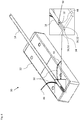
- Fig. 3 is a schematic view of the calibration apparatus 30 of Fig. 2 with the camera 12 disposed therein.
- Fig. 4 is a schematic view of the calibration apparatus 30 of Fig. 3 with the elongated strip 14 disposed on top of the camera 12.
- the calibration apparatus 30 includes a jig body 32, a lower groove 34, an upper groove 36, and two side grooves 38 disposed in the jig body 32.
- the lower groove 34 and the upper groove 36 follow a straight path from one end of the jig body 32 to the other.
- the lower groove 34 includes a first section 40 and a second section 42.
- the width of the second section 42 is wider than the width of the first section 40.
- the first section 40 is configured to receive and grasp the camera 12 therein, as shown in Fig. 3 .
- the second section is configured to receive connections 44 (only some labeled for the sake of simplicity) and wires 46 extending from the camera 12 also shown in Fig. 3 .
- the width and height of the first section 40 is sized to receive and grasp the camera 12 therein in order to ensure that the accuracy of the positioning between the camera 12 and the elongated strip 14 is within the calibration requirements.
- the gap between the width of the camera 12 and the width of the first section 40 is in the order of microns.
- the first section 40 of the lower groove 34 has a width in the range of 0.5 mm to 2 mm, e.g., 1 mm.
- the width of the first section 40 of the lower groove 34 may be any suitable width according to the size of the camera 12 and the calibration requirements.
- the height of the lower groove 34 may be in the range of 0.5 mm to 2 mm, e.g., 1 mm.
- the height (depth) of the lower groove 34 may be any suitable height according to the size of the camera 12 and the calibration requirements.
- the side grooves 38 extend away from the lower groove 34 to exit at either side of the jig body 32.
- the side grooves 38 are configured to receive therein the wires 46 extending from the camera 12 as shown in Fig. 3 .
- the side grooves 38 help keep the wires 46 away from the elongated strip 14 and prevent the wires 46 from applying upward pressure on the elongated strip 14 which may interfere with the correct position between the camera 12 and the elongated strip 14. Additionally, placing the wires 46 in the side grooves 38 helps stabilize the camera 12 in the first section 40 of the lower groove 34 and prevents forward or backward movement of the camera 12 in the lower groove 34.
- the upper groove 36 is disposed in the jig body 32 above the lower groove 34.
- the upper groove 36 is configured to receive and grasp the elongated strip 14 therein so as to position the elongated strip 14 above, and in a fixed relation to, the camera 12 as shown in Fig. 4 .
- the upper groove 36 is generally wider than the lower groove 34. In some embodiments, the upper groove 36 is disposed centrally above the lower groove 34. In other embodiments, the upper groove 36 may be disposed non-centrally above the lower groove 34.
- the lower groove 34 and upper groove 36 may be viewed as a single groove having a T-shape cross section and side-ledges 52 for resting the elongated strip 14 thereon.
- the upper groove 36 has a width in the range of 1 mm to 6 mm, e.g., 3 mm according to the width of the elongated strip 14. In other embodiments, the upper groove 36 may have any suitable width according to the width of the elongated strip 14 and the calibration requirements.
- the upper groove 36 has a height (depth) in the range of 0.05 mm to 0.15 mm, e.g., 0.08 mm.
- the height of the upper groove 36 may be set according to a thickness of the elongated strip 14. In other embodiments, the height of the upper groove 36 is not set according to the thickness of the elongated strip 14.
- the elongated strip 14 may be longer than the jig body 32.
- the upper groove 36 extends to at least one end of the jig body 32 to allow the elongated strip 14 to extend away from the jig body 32.
- the calibration apparatus 30 also includes an alignment element 48, which is disposed in the jig body 32, and is configured to align an end of the camera 12 with an end of the elongated strip 14.
- the alignment element 48 comprises an alignment post which is disposed in the lower groove 34 and extends at least up in to the upper groove 36.
- a surface of the lower groove 34 and the upper groove 36 may include a non-stick material such as polytetrafluoroethylene (PTFE) or Polyoxymethylene (POM) or any other suitable non-stick material.
- PTFE polytetrafluoroethylene
- POM Polyoxymethylene
- the jig body 32 is wholly formed from a non-stick material such as PTFE or POM.
- the jig body 32 may be any suitable size.
- the elongated strip 14 includes holes 50 therein through which to insert the adhesive.
- the elongated strip 14 may comprise any suitable materials such that the elongated strip 14 is deflectable and resilient.
- the elongated strip 14 is wholly formed from, or partially includes, Nitinol.
- Fig. 5 is a flowchart 60 including exemplary steps in a method of assembling the medical instrument 10 of Fig. 1 .
- the method of assembling the medical instrument 10 may include the following steps. Some of the steps may be performed in a different order than stated below.
- the method includes disposing (block 62) the camera 12 in the lower groove 34 of the jig body 32 with an end of the camera 12 abutting the alignment element 48 of the jig body 32 so that the lower groove 34 grasps the camera 12 therein.
- the method also includes disposing (block 64) camera wires 46 extending from the camera 12 in the side groove(s) 38 of the jig body 32 extending from the lower groove 34 to exit at a side of the jig body 32.
- the method also includes disposing (block 66) the elongated strip 14, which is deflectable and resilient, in the upper groove 36 of the jig body 32 with an end of the elongated strip 14 abutting the alignment element 48 so that the upper groove 36 grasps the elongated strip 14 above, in a fixed relation to, the camera 12.
- the method also includes applying (block 68) adhesive between the camera 12 and the elongated strip 14 to mechanically connect the camera 12 with the elongated strip 14.
- the elongated strip 14 comprises holes 50, and the adhesive is applied through the holes 50.
- the method also includes removing (block 70) the connected camera 12 and elongated strip 14 from the jig body 32 and disposing (block 72) the connected camera 12 and elongated strip 14, and optionally the light emitting diodes 16 and/or the irrigation tubes 18, in the medical instrument 10.
Landscapes
- Health & Medical Sciences (AREA)
- Life Sciences & Earth Sciences (AREA)
- Surgery (AREA)
- Engineering & Computer Science (AREA)
- Optics & Photonics (AREA)
- Physics & Mathematics (AREA)
- Biomedical Technology (AREA)
- Veterinary Medicine (AREA)
- Biophysics (AREA)
- Pathology (AREA)
- Radiology & Medical Imaging (AREA)
- Nuclear Medicine, Radiotherapy & Molecular Imaging (AREA)
- Public Health (AREA)
- Heart & Thoracic Surgery (AREA)
- Medical Informatics (AREA)
- Molecular Biology (AREA)
- Animal Behavior & Ethology (AREA)
- General Health & Medical Sciences (AREA)
- Manufacturing & Machinery (AREA)
- Microelectronics & Electronic Packaging (AREA)
- Mechanical Engineering (AREA)
- Endoscopes (AREA)
- Analysing Materials By The Use Of Radiation (AREA)
- Apparatus For Radiation Diagnosis (AREA)
Abstract
Description
- The present application claims benefit of
US Provisional Patent Application No. 62/829,517 of Algawi, et al., filed on April 4, 2019 - The present invention relates to medical instruments, and in particular, but not exclusively, to assembly of medical instruments.
- Medical instruments, for example, but not limited to, catheters, probes, and other instruments such as ENT tools, may include miniature cameras for capturing images within the body of a living subject. In order to provide useful data, the image capture equipment often needs to be calibrated after the medical instrument has been assembled prior to initial use.
-
US Patent Publication 2013/0281821 of Liu, et al. , describes a surgical navigation system employs an endoscope and an imaging unit. The endoscope includes an electromagnetic tracker within a working channel of the endoscope for generating electromagnetic sensing signals indicative of one or more poses of the endoscope within an anatomical region, and an endoscopic camera within an imaging channel of the endoscope for generating endoscopic images of the anatomical region. The imaging unit executes an intraoperative calibration of the electromagnetic tracker and the endoscopic camera as a function of an image registration between the preoperative scan image of a calibration site within the anatomical region and one or more endoscopic images of the calibration site within the anatomical region. -
US Patent 9,188,973 of Tenney, et al. - There is provided in accordance with an embodiment of the present disclosure, a calibration apparatus including a jig body, a camera, an elongated strip which is deflectable and resilient, a lower groove which is disposed in the jig body, and is configured to receive and grasp the camera therein, an upper groove, which is disposed in the jig body above the lower groove, and is configured to receive and grasp the elongated strip therein so as to position the elongated strip above, and in a fixed relation to, the camera, the upper groove being wider than the lower groove, and an alignment element, which is disposed in the jig body, and is configured to align an end of the camera with an end of the elongated strip.
- Further in accordance with an embodiment of the present disclosure the lower groove has a width in the range of 0.5 mm to 2 mm and a height in the range of 0.5 mm to 2 mm, and the upper groove has a width in the range of 1mm to 6mm.
- Still further in accordance with an embodiment of the present disclosure the lower groove includes a first section having a first width and a second section having a second width wider than the first width, the first section being configured to receive and grasp the camera therein, the second section being configured to receive connections and wires extending from the camera, the first width being in the range of 0.5mm to 2mm.
- Additionally, in accordance with an embodiment of the present disclosure the alignment element includes an alignment post which is disposed in the lower groove and extends at least up in to the upper groove.
- Moreover, in accordance with an embodiment of the present disclosure the upper groove is disposed centrally above the lower groove.
- Further in accordance with an embodiment of the present disclosure the upper groove has a height in the range of 0.05 mm to 0.15 mm.
- Still further in accordance with an embodiment of the present disclosure the jig body includes at least one side groove extending from the lower groove to exit at a side of the jig body, and configured to receive therein wires extending from the camera.
- Additionally, in accordance with an embodiment of the present disclosure a surface of the lower groove and the upper groove includes polytetrafluoroethylene (PTFE) or Polyoxymethylene (POM).
- Moreover, in accordance with an embodiment of the present disclosure the elongated strip includes Nitinol.
- There is also provided in accordance with another embodiment of the present disclosure, a medical instrument assembly method including disposing a camera in a lower groove of a jig body with an end of the camera abutting an alignment element of the jig body so that the lower groove grasps the camera therein, disposing an elongated strip, which is deflectable and resilient, in an upper groove of the jig body with an end of the elongated strip abutting the alignment element so that the upper groove grasps the elongated strip above, in a fixed relation to, the camera, the upper groove being wider than the lower groove, applying adhesive between the camera and the elongated strip to mechanically connect the camera with the elongated strip, removing the connected camera and elongated strip from the jig body, and disposing the connected camera and elongated strip in a medical instrument.
- Further in accordance with an embodiment of the present disclosure the lower groove has a width in the range of 0.5 mm to 2 mm and a height in the range of 0.5 mm to 2 mm, and the upper groove has a width in the range of 1mm to 6mm.
- Still further in accordance with an embodiment of the present disclosure the elongated strip includes holes, wherein the applying is performed by applying the adhesive through the holes.
- Additionally, in accordance with an embodiment of the present disclosure, the method includes disposing wires extending from the camera in at least one side groove of the jig body extending from the lower groove to exit at a side of the jig body.
- Moreover, in accordance with an embodiment of the present disclosure the elongated strip includes Nitinol.
- Further in accordance with an embodiment of the present disclosure, the method includes disposing light emitting diodes in the medical instrument.
- Still further in accordance with an embodiment of the present disclosure, the method includes disposing at least one irrigation tube in the medical instrument.
- Additionally in accordance with an embodiment of the present disclosure the lower groove includes a first section having a first width and a second section having a second width wider than the first width, the first section being configured to receive and grasp the camera therein, the second section being configured to receive connections and wires extending from the camera, the first width being in the range of 0.5mm to 2mm.
- Moreover, in accordance with an embodiment of the present disclosure the alignment element includes an alignment post which is disposed in the lower groove and extends at least up in to the upper groove.
- Further in accordance with an embodiment of the present disclosure the upper groove is disposed centrally above the lower groove.
- Still further in accordance with an embodiment of the present disclosure the upper groove has a height in the range of 0.05 mm to 0.15 mm.
- Additionally, in accordance with an embodiment of the present disclosure a surface of the lower groove and the upper groove includes polytetrafluoroethylene (PTFE) or Polyoxymethylene (POM).
- The present invention will be understood from the following detailed description, taken in conjunction with the drawings in which:
-
Fig. 1 is a schematic view of a medical instrument constructed and operative in accordance with an embodiment of the present invention; -
Fig. 2 is a schematic view of a calibration apparatus constructed and operative in accordance with an embodiment of the present invention; -
Fig. 3 is a schematic view of the calibration apparatus ofFig. 2 with a camera disposed therein; -
Fig. 4 is a schematic view of the calibration apparatus ofFig. 3 with an elongated strip disposed on top of the camera; and -
Fig. 5 is a flowchart including exemplary steps in a method of assembling the medical instrument ofFig. 1 . - As mentioned previously, medical instruments, for example, but not limited to, catheters, probes, and other medical instruments such as ENT tools, may include miniature cameras for capturing images within the body of a living subject. In order to provide useful data, the image capture equipment often needs to be calibrated after the medical instrument has been assembled and prior to initial use. The calibration process may be both time consuming and expensive. In some cases, performing calibration after assembly may be very difficult or even impossible.
- Embodiments of the present invention, provide a method to efficiently and accurately assemble (and with a reduced cost relative to methods that are known in the art) a medical instrument having a camera using a calibration apparatus including a jig body. The method allows a camera to be mechanically connected to a generally deflectable and resilient elongated strip in a predefined orientation and relative position to within a given accuracy so that a frame captured by the camera is substantially the same (within set calibration limits) as a frame captured by other, cameras and strips connected by the same method and calibration apparatus. Once one of the camera-strip combinations is calibrated, subsequent camera-strip combinations generally do not require further calibration or require less calibration. The elongated strip provides a base to the camera and other proximal components of the medical instrument described in more detail below. The elongated strip with the camera (and optionally other components) is disposed in a guidewire. The positioning of the elongated strip in the guidewire determines the direction in which the medical instrument may be deflected.
- The jig body includes various grooves for inserting a camera, the camera wires, and an elongated strip therein. In some embodiments, the grooves are sized and arranged so that the resulting connection between the camera and the elongated strip is accurate to about 0.1% or 1 micron of the desired connection orientation and position. In other embodiments, the accuracy may be more or less, for example, but not limited to, 1% or 10 microns.
- A lower groove in the jig body receives and grasps the camera therein. The lower groove includes a first section and a second section which is wider than the first section. It is the first section which receives and grasps the camera therein. The second section receives connections and wires extending from the camera. In some embodiments, the width of the first section may be in the range of 0.5 mm to 2 mm, according to the dimensions of the camera that the first section is intended to grasp. In some embodiments, the lower groove has a height in the range of 0.5 mm to 2 mm, according to the dimensions of the camera to be disposed therein. The width and height dimensions are not limited to the above exemplary values, but may be any suitable value.
- The jig body includes at least one side groove extending from the lower groove to exit at a side (or sides) of the jig body. The side grooves may be curved or straight and receive therein the wires extending from the camera.
- An upper groove is disposed in the jig body above the lower groove and typically continues to the end of the jig body. The upper groove receives and grasps the elongated strip therein so as to position the elongated strip above, and in a fixed relation to, the camera. The upper groove is wider than the lower groove, reflecting the fact that the elongated strip is generally wider than the camera. The upper groove may have any suitable width according to the width of the elongated strip, but in one embodiment the upper groove has a width in the range of 1mm to 6mm. The upper groove may have any suitable height equal to or greater than a thickness of the elongated strip. In some embodiments, the upper groove has a height in the range of 0.05 mm to 0.15 mm. In some embodiments, the upper groove is disposed centrally above the lower groove. However, in other embodiments, the upper groove may be disposed in an off-center alignment according to the desired connection orientation and position of the camera with respect to the elongated strip. As mentioned above the elongated strip is deflectable and resilient and may comprise Nitinol.
- The jig body includes an alignment element, which is disposed in the jig body, and is used to align an end of the camera with an end of the elongated strip. In some embodiments, the alignment element comprises an alignment post which is disposed in the lower groove and extends at least up in to the upper groove.
- Once the camera and elongated strip are suitably disposed in the jig body, adhesive is applied to mechanically connect the camera with the elongated strip. To prevent the camera and/or elongated strip becoming stuck with adhesive to the jig body, the surface of the lower groove, the upper groove, and possibly other parts of the jig body include a non-stick surface such as polytetrafluoroethylene (PTFE) or Polyoxymethylene (POM). In some embodiments, the jig body is wholly formed of a non-stick material such as PTFE or POM.
- The method to assemble the medical instrument includes disposing the camera in the lower groove of the jig body with an end of the camera abutting the alignment element of the jig body so that the lower groove grasps the camera therein and disposing wires extending from the camera in the side groove(s) of the jig body. The method also includes disposing the elongated strip in the upper groove of the jig body with an end of the elongated strip abutting the alignment element so that the upper groove grasps the elongated strip above, in a fixed relation to, the camera. The method also includes applying adhesive between the camera and the elongated strip to mechanically connect the camera with the elongated strip. In some embodiment, the elongated strip comprises holes, and the adhesive is applied through the holes. Once the adhesive has had time to sufficiently mechanically connect the elongated strip with the camera, the method then includes removing the connected camera and elongated strip from the jig body and disposing the connected camera and elongated strip in a medical instrument. In some embodiments light emitting diodes and/or at least one irrigation tube is disposed in the medical instrument.
- Reference is now made to
Fig. 1 , which is a schematic view of amedical instrument 10 constructed and operative in accordance with an embodiment of the present invention. Themedical instrument 10 may include aguidewire 20, for example but not limited to, a compressed coil, holding therein, acamera 12 mounted on an elongated strip 14 (only the end of theelongated strip 14 is visible inFig. 1 ), one or morelight emitting diodes 16, and one ormore irrigation tubes 18. In some embodiments, theguidewire 20 may be disposed within a suitable sheath (not shown). In some embodiments, themedical instrument 10 may omit thelight emitting diodes 16 and/or theirrigation tubes 18. In other embodiments, thecamera 12 and theelongated strip 14 and optionally thelight emitting diodes 16 and/or theirrigation tubes 18 may be disposed in any suitable medical instrument which may, or may not, include theguidewire 20. The medical instrument may be a medical probe, or a catheter or any suitable medical instrument such as an ENT tool, by way of example only. Theelongated strip 14 provides a base to thecamera 12 and other proximal components (e.g., thelight emitting diodes 16 and the irrigation tubes 18) of themedical instrument 10. The positioning of theelongated strip 14 in theguidewire 20 determines the direction in which themedical instrument 10 may be deflected. - Reference is now made to
Figs. 2-4 .Fig. 2 is a schematic view of acalibration apparatus 30 constructed and operative in accordance with an embodiment of the present invention.Fig. 3 is a schematic view of thecalibration apparatus 30 ofFig. 2 with thecamera 12 disposed therein.Fig. 4 is a schematic view of thecalibration apparatus 30 ofFig. 3 with theelongated strip 14 disposed on top of thecamera 12. - The
calibration apparatus 30 includes ajig body 32, alower groove 34, an upper groove 36, and twoside grooves 38 disposed in thejig body 32. In some embodiments, thelower groove 34 and the upper groove 36 follow a straight path from one end of thejig body 32 to the other. - The
lower groove 34 includes afirst section 40 and asecond section 42. The width of thesecond section 42 is wider than the width of thefirst section 40. Thefirst section 40 is configured to receive and grasp thecamera 12 therein, as shown inFig. 3 . The second section is configured to receive connections 44 (only some labeled for the sake of simplicity) andwires 46 extending from thecamera 12 also shown inFig. 3 . The width and height of thefirst section 40 is sized to receive and grasp thecamera 12 therein in order to ensure that the accuracy of the positioning between thecamera 12 and theelongated strip 14 is within the calibration requirements. In some embodiments, the gap between the width of thecamera 12 and the width of thefirst section 40 is in the order of microns. In some embodiments thefirst section 40 of thelower groove 34 has a width in the range of 0.5 mm to 2 mm, e.g., 1 mm. The width of thefirst section 40 of thelower groove 34 may be any suitable width according to the size of thecamera 12 and the calibration requirements. In some embodiments, the height of thelower groove 34 may be in the range of 0.5 mm to 2 mm, e.g., 1 mm. The height (depth) of thelower groove 34 may be any suitable height according to the size of thecamera 12 and the calibration requirements. - The
side grooves 38 extend away from thelower groove 34 to exit at either side of thejig body 32. Theside grooves 38 are configured to receive therein thewires 46 extending from thecamera 12 as shown inFig. 3 . Theside grooves 38 help keep thewires 46 away from theelongated strip 14 and prevent thewires 46 from applying upward pressure on theelongated strip 14 which may interfere with the correct position between thecamera 12 and theelongated strip 14. Additionally, placing thewires 46 in theside grooves 38 helps stabilize thecamera 12 in thefirst section 40 of thelower groove 34 and prevents forward or backward movement of thecamera 12 in thelower groove 34. - The upper groove 36 is disposed in the
jig body 32 above thelower groove 34. The upper groove 36 is configured to receive and grasp theelongated strip 14 therein so as to position theelongated strip 14 above, and in a fixed relation to, thecamera 12 as shown inFig. 4 . - The upper groove 36 is generally wider than the
lower groove 34. In some embodiments, the upper groove 36 is disposed centrally above thelower groove 34. In other embodiments, the upper groove 36 may be disposed non-centrally above thelower groove 34. - The
lower groove 34 and upper groove 36 may be viewed as a single groove having a T-shape cross section and side-ledges 52 for resting theelongated strip 14 thereon. - In some embodiments, the upper groove 36 has a width in the range of 1 mm to 6 mm, e.g., 3 mm according to the width of the
elongated strip 14. In other embodiments, the upper groove 36 may have any suitable width according to the width of theelongated strip 14 and the calibration requirements. - In some embodiments, the upper groove 36 has a height (depth) in the range of 0.05 mm to 0.15 mm, e.g., 0.08 mm. The height of the upper groove 36 may be set according to a thickness of the
elongated strip 14. In other embodiments, the height of the upper groove 36 is not set according to the thickness of theelongated strip 14. - The
elongated strip 14 may be longer than thejig body 32. In such a case, the upper groove 36 extends to at least one end of thejig body 32 to allow theelongated strip 14 to extend away from thejig body 32. - The
calibration apparatus 30 also includes analignment element 48, which is disposed in thejig body 32, and is configured to align an end of thecamera 12 with an end of theelongated strip 14. In some embodiments, thealignment element 48 comprises an alignment post which is disposed in thelower groove 34 and extends at least up in to the upper groove 36. - As will be described in more detail with reference to
Fig. 5 , thecamera 12 and theelongated strip 14 are mechanically connected together using an adhesive. To prevent thecamera 12 and/or theelongated strip 14 from becoming stuck with the adhesive to thejig body 32, a surface of thelower groove 34 and the upper groove 36 may include a non-stick material such as polytetrafluoroethylene (PTFE) or Polyoxymethylene (POM) or any other suitable non-stick material. In some embodiments, thejig body 32 is wholly formed from a non-stick material such as PTFE or POM. Thejig body 32 may be any suitable size. - In some embodiments, the
elongated strip 14 includesholes 50 therein through which to insert the adhesive. Theelongated strip 14 may comprise any suitable materials such that theelongated strip 14 is deflectable and resilient. In some embodiments, theelongated strip 14 is wholly formed from, or partially includes, Nitinol. - Reference is now made to
Fig. 5 , which is aflowchart 60 including exemplary steps in a method of assembling themedical instrument 10 ofFig. 1 . Reference is also made toFigs. 1-5 . The method of assembling themedical instrument 10 may include the following steps. Some of the steps may be performed in a different order than stated below. - The method includes disposing (block 62) the
camera 12 in thelower groove 34 of thejig body 32 with an end of thecamera 12 abutting thealignment element 48 of thejig body 32 so that thelower groove 34 grasps thecamera 12 therein. - The method also includes disposing (block 64)
camera wires 46 extending from thecamera 12 in the side groove(s) 38 of thejig body 32 extending from thelower groove 34 to exit at a side of thejig body 32. - The method also includes disposing (block 66) the
elongated strip 14, which is deflectable and resilient, in the upper groove 36 of thejig body 32 with an end of theelongated strip 14 abutting thealignment element 48 so that the upper groove 36 grasps theelongated strip 14 above, in a fixed relation to, thecamera 12. - The method also includes applying (block 68) adhesive between the
camera 12 and theelongated strip 14 to mechanically connect thecamera 12 with theelongated strip 14. In some embodiments, theelongated strip 14 comprisesholes 50, and the adhesive is applied through theholes 50. - The method also includes removing (block 70) the connected
camera 12 andelongated strip 14 from thejig body 32 and disposing (block 72) the connectedcamera 12 andelongated strip 14, and optionally thelight emitting diodes 16 and/or theirrigation tubes 18, in themedical instrument 10. - Various features of the invention which are, for clarity, described in the contexts of separate embodiments may also be provided in combination in a single embodiment. Conversely, various features of the invention which are, for brevity, described in the context of a single embodiment may also be provided separately or in any suitable sub-combination.
- The embodiments described above are cited by way of example, and the present invention is not limited by what has been particularly shown and described hereinabove. Rather the scope of the invention includes both combinations and subcombinations of the various features described hereinabove, as well as variations and modifications thereof which would occur to persons skilled in the art upon reading the foregoing description and which are not disclosed in the prior art.
Claims (14)
- A calibration apparatus, comprising:a jig body;a camera;an elongated strip which is deflectable and resilient;a lower groove which is disposed in the jig body, and is configured to receive and grasp the camera therein;an upper groove, which is disposed in the jig body above the lower groove, and is configured to receive and grasp the elongated strip therein so as to position the elongated strip above, and in a fixed relation to, the camera, the upper groove being wider than the lower groove; andan alignment element, which is disposed in the jig body, and is configured to align an end of the camera with an end of the elongated strip.
- The apparatus according to claim 1, wherein the jig body includes at least one side groove extending from the lower groove to exit at a side of the jig body, and configured to receive therein wires extending from the camera.
- A medical instrument assembly method, comprising:disposing a camera in a lower groove of a jig body with an end of the camera abutting an alignment element of the jig body so that the lower groove grasps the camera therein;disposing an elongated strip, which is deflectable and resilient, in an upper groove of the jig body with an end of the elongated strip abutting the alignment element so that the upper groove grasps the elongated strip above, in a fixed relation to, the camera, the upper groove being wider than the lower groove;applying adhesive between the camera and the elongated strip to mechanically connect the camera with the elongated strip;removing the connected camera and elongated strip from the jig body; anddisposing the connected camera and elongated strip in a medical instrument.
- The apparatus according to claim 1 or the method according to claim 3, wherein: the lower groove has a width in the range of 0.5 mm to 2 mm and a height in the range of 0.5 mm to 2 mm; and the upper groove has a width in the range of 1mm to 6mm.
- The method according to claim 3, wherein the elongated strip comprises holes, wherein the applying is performed by applying the adhesive through the holes.
- The method according to claim 3, further comprising disposing wires extending from the camera in at least one side groove of the jig body extending from the lower groove to exit at a side of the jig body.
- The apparatus according to claim 1 or the method according to claim 3, wherein the elongated strip comprises Nitinol.
- The method according to claim 3, further comprising disposing light emitting diodes in the medical instrument.
- The method according to claim 3, further comprising disposing at least one irrigation tube in the medical instrument.
- The apparatus according to claim 1 or the method according to claim 3, wherein the lower groove includes a first section having a first width and a second section having a second width wider than the first width, the first section being configured to receive and grasp the camera therein, the second section being configured to receive connections and wires extending from the camera, the first width being in the range of 0.5mm to 2mm..
- The apparatus according to claim 1 or the method according to claim 3, wherein the alignment element comprises an alignment post which is disposed in the lower groove and extends at least up in to the upper groove.
- The apparatus according to claim 1 or the method according to claim 3, wherein the upper groove is disposed centrally above the lower groove.
- The apparatus according to claim 1 or the method according to claim 3, wherein the upper groove has a height in the range of 0.05 mm to 0.15 mm.
- The apparatus according to claim 1 or the method according to claim 3, wherein a surface of the lower groove and the upper groove includes polytetrafluoroethylene (PTFE) or Polyoxymethylene (POM).
Applications Claiming Priority (2)
| Application Number | Priority Date | Filing Date | Title |
|---|---|---|---|
| US201962829517P | 2019-04-04 | 2019-04-04 | |
| US16/797,634 US11259687B2 (en) | 2019-04-04 | 2020-02-21 | Medical instrument calibration |
Publications (2)
| Publication Number | Publication Date |
|---|---|
| EP3718465A1 true EP3718465A1 (en) | 2020-10-07 |
| EP3718465B1 EP3718465B1 (en) | 2023-07-26 |
Family
ID=70189680
Family Applications (1)
| Application Number | Title | Priority Date | Filing Date |
|---|---|---|---|
| EP20167943.8A Active EP3718465B1 (en) | 2019-04-04 | 2020-04-03 | Medical instrument calibration |
Country Status (5)
| Country | Link |
|---|---|
| US (1) | US11259687B2 (en) |
| EP (1) | EP3718465B1 (en) |
| JP (1) | JP7512066B2 (en) |
| CN (1) | CN111789566A (en) |
| IL (1) | IL273466B2 (en) |
Families Citing this family (1)
| Publication number | Priority date | Publication date | Assignee | Title |
|---|---|---|---|---|
| US11259687B2 (en) * | 2019-04-04 | 2022-03-01 | Biosense Webster (Israel) Ltd. | Medical instrument calibration |
Citations (6)
| Publication number | Priority date | Publication date | Assignee | Title |
|---|---|---|---|---|
| EP1111386A2 (en) * | 1999-12-17 | 2001-06-27 | Bayer Corporation | Test strip for the assay of an analyte in a liquid sample |
| WO2009140757A1 (en) * | 2008-05-20 | 2009-11-26 | University Health Network | Device and method for fluorescence-based imaging and monitoring |
| WO2011010632A1 (en) * | 2009-07-22 | 2011-01-27 | 富士フイルム株式会社 | Calibration method and device, and endoscope system |
| WO2012096102A1 (en) * | 2011-01-14 | 2012-07-19 | コニカミノルタオプト株式会社 | Probe, optical measurement system, provision method, and packaged article for diagnosis purposes |
| US20130281821A1 (en) | 2011-01-13 | 2013-10-24 | Koninklijke Philips Electronics N.V. | Intraoperative camera calibration for endoscopic surgery |
| US9188973B2 (en) | 2011-07-08 | 2015-11-17 | Restoration Robotics, Inc. | Calibration and transformation of a camera system's coordinate system |
Family Cites Families (15)
| Publication number | Priority date | Publication date | Assignee | Title |
|---|---|---|---|---|
| US3872567A (en) * | 1974-03-26 | 1975-03-25 | Amp Inc | Wire locating jig and fixture |
| US5945635A (en) * | 1994-12-28 | 1999-08-31 | Sumitomo Wiring Systems, Ltd. | Wire assembly apparatus and method for assembling wires |
| JP5145299B2 (en) * | 2009-07-31 | 2013-02-13 | 富士フイルム株式会社 | Calibration method and apparatus |
| US20130190561A1 (en) * | 2012-01-10 | 2013-07-25 | Boston Scientific Scimed, Inc. | Steerable medical device having an imaging system |
| US9433752B2 (en) | 2012-11-14 | 2016-09-06 | Biosense Webster (Israel) Ltd. | Catheter with flat beam deflection in tip |
| JP6137824B2 (en) | 2012-12-13 | 2017-05-31 | オリンパス株式会社 | Imaging unit, endoscope apparatus, and manufacturing method of imaging unit |
| JP2015047249A (en) | 2013-08-30 | 2015-03-16 | パナソニック株式会社 | Endoscope |
| JP2016534837A (en) * | 2013-09-12 | 2016-11-10 | ボストン サイエンティフィック サイムド,インコーポレイテッドBoston Scientific Scimed,Inc. | Medical device with movable tip |
| WO2015174444A1 (en) | 2014-05-16 | 2015-11-19 | オリンパス株式会社 | Image pickup device for endoscope, and method of assembling image pickup device for endoscope |
| US10683476B2 (en) | 2014-05-29 | 2020-06-16 | Icahn School Of Medicine At Mount Sinai | Method and apparatus to prepare cardiac organoids in a bioreactor system |
| US20170087873A1 (en) * | 2015-07-06 | 2017-03-30 | Custom Engraving, Inc. | Method of ablating and printing on firearms and the resulting product |
| US9838576B2 (en) | 2015-08-31 | 2017-12-05 | Panasonic Corporation | Endoscope |
| US11141071B2 (en) | 2016-06-16 | 2021-10-12 | Stryker European Operations Limited | Closed cavity adjustable sensor mount systems and methods |
| EP3451908A4 (en) | 2016-06-29 | 2019-11-06 | Piccolo Medical, Inc. | DEVICES FOR NAVIGATION, EVALUATION AND / OR VASCULAR DIAGNOSIS. |
| US11259687B2 (en) * | 2019-04-04 | 2022-03-01 | Biosense Webster (Israel) Ltd. | Medical instrument calibration |
-
2020
- 2020-02-21 US US16/797,634 patent/US11259687B2/en active Active
- 2020-03-19 IL IL273466A patent/IL273466B2/en unknown
- 2020-04-03 JP JP2020067394A patent/JP7512066B2/en active Active
- 2020-04-03 EP EP20167943.8A patent/EP3718465B1/en active Active
- 2020-04-03 CN CN202010259256.XA patent/CN111789566A/en active Pending
Patent Citations (6)
| Publication number | Priority date | Publication date | Assignee | Title |
|---|---|---|---|---|
| EP1111386A2 (en) * | 1999-12-17 | 2001-06-27 | Bayer Corporation | Test strip for the assay of an analyte in a liquid sample |
| WO2009140757A1 (en) * | 2008-05-20 | 2009-11-26 | University Health Network | Device and method for fluorescence-based imaging and monitoring |
| WO2011010632A1 (en) * | 2009-07-22 | 2011-01-27 | 富士フイルム株式会社 | Calibration method and device, and endoscope system |
| US20130281821A1 (en) | 2011-01-13 | 2013-10-24 | Koninklijke Philips Electronics N.V. | Intraoperative camera calibration for endoscopic surgery |
| WO2012096102A1 (en) * | 2011-01-14 | 2012-07-19 | コニカミノルタオプト株式会社 | Probe, optical measurement system, provision method, and packaged article for diagnosis purposes |
| US9188973B2 (en) | 2011-07-08 | 2015-11-17 | Restoration Robotics, Inc. | Calibration and transformation of a camera system's coordinate system |
Also Published As
| Publication number | Publication date |
|---|---|
| JP2020168369A (en) | 2020-10-15 |
| JP7512066B2 (en) | 2024-07-08 |
| IL273466B2 (en) | 2023-07-01 |
| US20200315427A1 (en) | 2020-10-08 |
| US11259687B2 (en) | 2022-03-01 |
| IL273466B1 (en) | 2023-03-01 |
| EP3718465B1 (en) | 2023-07-26 |
| CN111789566A (en) | 2020-10-20 |
| IL273466A (en) | 2020-10-29 |
Similar Documents
| Publication | Publication Date | Title |
|---|---|---|
| US12472004B2 (en) | Surgical instrument and method for detecting the position of a surgical instrument | |
| US10743748B2 (en) | Endoscope structures and techniques for navigating to a target in branched structure | |
| EP1499235B1 (en) | Endoscope structures and techniques for navigating to a target in branched structure | |
| CN107970074B (en) | Head alignment using personalized fixtures | |
| KR101491922B1 (en) | Hybrid navigation system and method to track position thereof | |
| US8064985B2 (en) | System and method for determining the position of a flexible instrument used in a tracking system | |
| JP2004237100A (en) | Surgical instrument | |
| CN114340518A (en) | sinus shaping tool | |
| JP7323489B2 (en) | Systems and associated methods and apparatus for robotic guidance of a guided biopsy needle trajectory | |
| US11259687B2 (en) | Medical instrument calibration | |
| CN113558764B (en) | Field generator assembly and method for surgical navigation | |
| KR101863574B1 (en) | Application method to fluoroscopy in laser guidance system, recording medium and laser guidance system including calibration tool for performing the method | |
| CN120603548A (en) | Method and system for tracking multiple optical markers in robotic surgical procedures | |
| US12251168B2 (en) | Systems, methods, and devices for localized tracking of a vertebral body or other anatomic structure | |
| CN120769732A (en) | Devices used in computer-assisted surgery | |
| KR20190038042A (en) | Image processing method |
Legal Events
| Date | Code | Title | Description |
|---|---|---|---|
| PUAI | Public reference made under article 153(3) epc to a published international application that has entered the european phase |
Free format text: ORIGINAL CODE: 0009012 |
|
| STAA | Information on the status of an ep patent application or granted ep patent |
Free format text: STATUS: THE APPLICATION HAS BEEN PUBLISHED |
|
| AK | Designated contracting states |
Kind code of ref document: A1 Designated state(s): AL AT BE BG CH CY CZ DE DK EE ES FI FR GB GR HR HU IE IS IT LI LT LU LV MC MK MT NL NO PL PT RO RS SE SI SK SM TR |
|
| AX | Request for extension of the european patent |
Extension state: BA ME |
|
| STAA | Information on the status of an ep patent application or granted ep patent |
Free format text: STATUS: REQUEST FOR EXAMINATION WAS MADE |
|
| 17P | Request for examination filed |
Effective date: 20210312 |
|
| RBV | Designated contracting states (corrected) |
Designated state(s): AL AT BE BG CH CY CZ DE DK EE ES FI FR GB GR HR HU IE IS IT LI LT LU LV MC MK MT NL NO PL PT RO RS SE SI SK SM TR |
|
| RAP3 | Party data changed (applicant data changed or rights of an application transferred) |
Owner name: BIOSENSE WEBSTER (ISRAEL) LTD. |
|
| GRAP | Despatch of communication of intention to grant a patent |
Free format text: ORIGINAL CODE: EPIDOSNIGR1 |
|
| STAA | Information on the status of an ep patent application or granted ep patent |
Free format text: STATUS: GRANT OF PATENT IS INTENDED |
|
| RIC1 | Information provided on ipc code assigned before grant |
Ipc: A61B 1/00 20060101AFI20230223BHEP |
|
| INTG | Intention to grant announced |
Effective date: 20230314 |
|
| GRAJ | Information related to disapproval of communication of intention to grant by the applicant or resumption of examination proceedings by the epo deleted |
Free format text: ORIGINAL CODE: EPIDOSDIGR1 |
|
| STAA | Information on the status of an ep patent application or granted ep patent |
Free format text: STATUS: REQUEST FOR EXAMINATION WAS MADE |
|
| GRAP | Despatch of communication of intention to grant a patent |
Free format text: ORIGINAL CODE: EPIDOSNIGR1 |
|
| STAA | Information on the status of an ep patent application or granted ep patent |
Free format text: STATUS: GRANT OF PATENT IS INTENDED |
|
| INTC | Intention to grant announced (deleted) | ||
| INTG | Intention to grant announced |
Effective date: 20230512 |
|
| GRAS | Grant fee paid |
Free format text: ORIGINAL CODE: EPIDOSNIGR3 |
|
| GRAA | (expected) grant |
Free format text: ORIGINAL CODE: 0009210 |
|
| STAA | Information on the status of an ep patent application or granted ep patent |
Free format text: STATUS: THE PATENT HAS BEEN GRANTED |
|
| AK | Designated contracting states |
Kind code of ref document: B1 Designated state(s): AL AT BE BG CH CY CZ DE DK EE ES FI FR GB GR HR HU IE IS IT LI LT LU LV MC MK MT NL NO PL PT RO RS SE SI SK SM TR |
|
| REG | Reference to a national code |
Ref country code: CH Ref legal event code: EP |
|
| REG | Reference to a national code |
Ref country code: IE Ref legal event code: FG4D |
|
| REG | Reference to a national code |
Ref country code: DE Ref legal event code: R096 Ref document number: 602020014283 Country of ref document: DE |
|
| REG | Reference to a national code |
Ref country code: LT Ref legal event code: MG9D |
|
| REG | Reference to a national code |
Ref country code: NL Ref legal event code: MP Effective date: 20230726 |
|
| REG | Reference to a national code |
Ref country code: AT Ref legal event code: MK05 Ref document number: 1590949 Country of ref document: AT Kind code of ref document: T Effective date: 20230726 |
|
| PG25 | Lapsed in a contracting state [announced via postgrant information from national office to epo] |
Ref country code: NL Free format text: LAPSE BECAUSE OF FAILURE TO SUBMIT A TRANSLATION OF THE DESCRIPTION OR TO PAY THE FEE WITHIN THE PRESCRIBED TIME-LIMIT Effective date: 20230726 |
|
| PG25 | Lapsed in a contracting state [announced via postgrant information from national office to epo] |
Ref country code: GR Free format text: LAPSE BECAUSE OF FAILURE TO SUBMIT A TRANSLATION OF THE DESCRIPTION OR TO PAY THE FEE WITHIN THE PRESCRIBED TIME-LIMIT Effective date: 20231027 |
|
| PG25 | Lapsed in a contracting state [announced via postgrant information from national office to epo] |
Ref country code: IS Free format text: LAPSE BECAUSE OF FAILURE TO SUBMIT A TRANSLATION OF THE DESCRIPTION OR TO PAY THE FEE WITHIN THE PRESCRIBED TIME-LIMIT Effective date: 20231126 |
|
| PG25 | Lapsed in a contracting state [announced via postgrant information from national office to epo] |
Ref country code: SE Free format text: LAPSE BECAUSE OF FAILURE TO SUBMIT A TRANSLATION OF THE DESCRIPTION OR TO PAY THE FEE WITHIN THE PRESCRIBED TIME-LIMIT Effective date: 20230726 Ref country code: RS Free format text: LAPSE BECAUSE OF FAILURE TO SUBMIT A TRANSLATION OF THE DESCRIPTION OR TO PAY THE FEE WITHIN THE PRESCRIBED TIME-LIMIT Effective date: 20230726 Ref country code: PT Free format text: LAPSE BECAUSE OF FAILURE TO SUBMIT A TRANSLATION OF THE DESCRIPTION OR TO PAY THE FEE WITHIN THE PRESCRIBED TIME-LIMIT Effective date: 20231127 Ref country code: NO Free format text: LAPSE BECAUSE OF FAILURE TO SUBMIT A TRANSLATION OF THE DESCRIPTION OR TO PAY THE FEE WITHIN THE PRESCRIBED TIME-LIMIT Effective date: 20231026 Ref country code: LV Free format text: LAPSE BECAUSE OF FAILURE TO SUBMIT A TRANSLATION OF THE DESCRIPTION OR TO PAY THE FEE WITHIN THE PRESCRIBED TIME-LIMIT Effective date: 20230726 Ref country code: LT Free format text: LAPSE BECAUSE OF FAILURE TO SUBMIT A TRANSLATION OF THE DESCRIPTION OR TO PAY THE FEE WITHIN THE PRESCRIBED TIME-LIMIT Effective date: 20230726 Ref country code: IS Free format text: LAPSE BECAUSE OF FAILURE TO SUBMIT A TRANSLATION OF THE DESCRIPTION OR TO PAY THE FEE WITHIN THE PRESCRIBED TIME-LIMIT Effective date: 20231126 Ref country code: HR Free format text: LAPSE BECAUSE OF FAILURE TO SUBMIT A TRANSLATION OF THE DESCRIPTION OR TO PAY THE FEE WITHIN THE PRESCRIBED TIME-LIMIT Effective date: 20230726 Ref country code: GR Free format text: LAPSE BECAUSE OF FAILURE TO SUBMIT A TRANSLATION OF THE DESCRIPTION OR TO PAY THE FEE WITHIN THE PRESCRIBED TIME-LIMIT Effective date: 20231027 Ref country code: FI Free format text: LAPSE BECAUSE OF FAILURE TO SUBMIT A TRANSLATION OF THE DESCRIPTION OR TO PAY THE FEE WITHIN THE PRESCRIBED TIME-LIMIT Effective date: 20230726 Ref country code: AT Free format text: LAPSE BECAUSE OF FAILURE TO SUBMIT A TRANSLATION OF THE DESCRIPTION OR TO PAY THE FEE WITHIN THE PRESCRIBED TIME-LIMIT Effective date: 20230726 |
|
| PG25 | Lapsed in a contracting state [announced via postgrant information from national office to epo] |
Ref country code: PL Free format text: LAPSE BECAUSE OF FAILURE TO SUBMIT A TRANSLATION OF THE DESCRIPTION OR TO PAY THE FEE WITHIN THE PRESCRIBED TIME-LIMIT Effective date: 20230726 |
|
| PG25 | Lapsed in a contracting state [announced via postgrant information from national office to epo] |
Ref country code: ES Free format text: LAPSE BECAUSE OF FAILURE TO SUBMIT A TRANSLATION OF THE DESCRIPTION OR TO PAY THE FEE WITHIN THE PRESCRIBED TIME-LIMIT Effective date: 20230726 |
|
| REG | Reference to a national code |
Ref country code: DE Ref legal event code: R097 Ref document number: 602020014283 Country of ref document: DE |
|
| PG25 | Lapsed in a contracting state [announced via postgrant information from national office to epo] |
Ref country code: SM Free format text: LAPSE BECAUSE OF FAILURE TO SUBMIT A TRANSLATION OF THE DESCRIPTION OR TO PAY THE FEE WITHIN THE PRESCRIBED TIME-LIMIT Effective date: 20230726 Ref country code: RO Free format text: LAPSE BECAUSE OF FAILURE TO SUBMIT A TRANSLATION OF THE DESCRIPTION OR TO PAY THE FEE WITHIN THE PRESCRIBED TIME-LIMIT Effective date: 20230726 Ref country code: ES Free format text: LAPSE BECAUSE OF FAILURE TO SUBMIT A TRANSLATION OF THE DESCRIPTION OR TO PAY THE FEE WITHIN THE PRESCRIBED TIME-LIMIT Effective date: 20230726 Ref country code: EE Free format text: LAPSE BECAUSE OF FAILURE TO SUBMIT A TRANSLATION OF THE DESCRIPTION OR TO PAY THE FEE WITHIN THE PRESCRIBED TIME-LIMIT Effective date: 20230726 Ref country code: DK Free format text: LAPSE BECAUSE OF FAILURE TO SUBMIT A TRANSLATION OF THE DESCRIPTION OR TO PAY THE FEE WITHIN THE PRESCRIBED TIME-LIMIT Effective date: 20230726 Ref country code: CZ Free format text: LAPSE BECAUSE OF FAILURE TO SUBMIT A TRANSLATION OF THE DESCRIPTION OR TO PAY THE FEE WITHIN THE PRESCRIBED TIME-LIMIT Effective date: 20230726 Ref country code: SK Free format text: LAPSE BECAUSE OF FAILURE TO SUBMIT A TRANSLATION OF THE DESCRIPTION OR TO PAY THE FEE WITHIN THE PRESCRIBED TIME-LIMIT Effective date: 20230726 |
|
| PLBE | No opposition filed within time limit |
Free format text: ORIGINAL CODE: 0009261 |
|
| STAA | Information on the status of an ep patent application or granted ep patent |
Free format text: STATUS: NO OPPOSITION FILED WITHIN TIME LIMIT |
|
| 26N | No opposition filed |
Effective date: 20240429 |
|
| PG25 | Lapsed in a contracting state [announced via postgrant information from national office to epo] |
Ref country code: SI Free format text: LAPSE BECAUSE OF FAILURE TO SUBMIT A TRANSLATION OF THE DESCRIPTION OR TO PAY THE FEE WITHIN THE PRESCRIBED TIME-LIMIT Effective date: 20230726 |
|
| PG25 | Lapsed in a contracting state [announced via postgrant information from national office to epo] |
Ref country code: BG Free format text: LAPSE BECAUSE OF FAILURE TO SUBMIT A TRANSLATION OF THE DESCRIPTION OR TO PAY THE FEE WITHIN THE PRESCRIBED TIME-LIMIT Effective date: 20230726 |
|
| PG25 | Lapsed in a contracting state [announced via postgrant information from national office to epo] |
Ref country code: MC Free format text: LAPSE BECAUSE OF FAILURE TO SUBMIT A TRANSLATION OF THE DESCRIPTION OR TO PAY THE FEE WITHIN THE PRESCRIBED TIME-LIMIT Effective date: 20230726 |
|
| PG25 | Lapsed in a contracting state [announced via postgrant information from national office to epo] |
Ref country code: MC Free format text: LAPSE BECAUSE OF FAILURE TO SUBMIT A TRANSLATION OF THE DESCRIPTION OR TO PAY THE FEE WITHIN THE PRESCRIBED TIME-LIMIT Effective date: 20230726 Ref country code: BG Free format text: LAPSE BECAUSE OF FAILURE TO SUBMIT A TRANSLATION OF THE DESCRIPTION OR TO PAY THE FEE WITHIN THE PRESCRIBED TIME-LIMIT Effective date: 20230726 |
|
| REG | Reference to a national code |
Ref country code: CH Ref legal event code: PL |
|
| PG25 | Lapsed in a contracting state [announced via postgrant information from national office to epo] |
Ref country code: LU Free format text: LAPSE BECAUSE OF NON-PAYMENT OF DUE FEES Effective date: 20240403 |
|
| REG | Reference to a national code |
Ref country code: BE Ref legal event code: MM Effective date: 20240430 |
|
| PG25 | Lapsed in a contracting state [announced via postgrant information from national office to epo] |
Ref country code: LU Free format text: LAPSE BECAUSE OF NON-PAYMENT OF DUE FEES Effective date: 20240403 |
|
| PG25 | Lapsed in a contracting state [announced via postgrant information from national office to epo] |
Ref country code: BE Free format text: LAPSE BECAUSE OF NON-PAYMENT OF DUE FEES Effective date: 20240430 |
|
| PG25 | Lapsed in a contracting state [announced via postgrant information from national office to epo] |
Ref country code: BE Free format text: LAPSE BECAUSE OF NON-PAYMENT OF DUE FEES Effective date: 20240430 Ref country code: CH Free format text: LAPSE BECAUSE OF NON-PAYMENT OF DUE FEES Effective date: 20240430 |
|
| PG25 | Lapsed in a contracting state [announced via postgrant information from national office to epo] |
Ref country code: IE Free format text: LAPSE BECAUSE OF NON-PAYMENT OF DUE FEES Effective date: 20240403 |
|
| PGFP | Annual fee paid to national office [announced via postgrant information from national office to epo] |
Ref country code: GB Payment date: 20250306 Year of fee payment: 6 |
|
| PGFP | Annual fee paid to national office [announced via postgrant information from national office to epo] |
Ref country code: DE Payment date: 20250305 Year of fee payment: 6 |
|
| PG25 | Lapsed in a contracting state [announced via postgrant information from national office to epo] |
Ref country code: CY Free format text: LAPSE BECAUSE OF FAILURE TO SUBMIT A TRANSLATION OF THE DESCRIPTION OR TO PAY THE FEE WITHIN THE PRESCRIBED TIME-LIMIT; INVALID AB INITIO Effective date: 20200403 |
|
| PG25 | Lapsed in a contracting state [announced via postgrant information from national office to epo] |
Ref country code: HU Free format text: LAPSE BECAUSE OF FAILURE TO SUBMIT A TRANSLATION OF THE DESCRIPTION OR TO PAY THE FEE WITHIN THE PRESCRIBED TIME-LIMIT; INVALID AB INITIO Effective date: 20200403 |
|
| PG25 | Lapsed in a contracting state [announced via postgrant information from national office to epo] |
Ref country code: TR Free format text: LAPSE BECAUSE OF FAILURE TO SUBMIT A TRANSLATION OF THE DESCRIPTION OR TO PAY THE FEE WITHIN THE PRESCRIBED TIME-LIMIT Effective date: 20230726 |
|
| PGFP | Annual fee paid to national office [announced via postgrant information from national office to epo] |
Ref country code: IT Payment date: 20260320 Year of fee payment: 7 |
|
| PGFP | Annual fee paid to national office [announced via postgrant information from national office to epo] |
Ref country code: FR Payment date: 20260309 Year of fee payment: 7 |