EP3718293B1 - Electronic device and method of detecting status of battery thereof - Google Patents
Electronic device and method of detecting status of battery thereof Download PDFInfo
- Publication number
- EP3718293B1 EP3718293B1 EP19740784.4A EP19740784A EP3718293B1 EP 3718293 B1 EP3718293 B1 EP 3718293B1 EP 19740784 A EP19740784 A EP 19740784A EP 3718293 B1 EP3718293 B1 EP 3718293B1
- Authority
- EP
- European Patent Office
- Prior art keywords
- electronic device
- battery
- gas
- processor
- sensor
- Prior art date
- Legal status (The legal status is an assumption and is not a legal conclusion. Google has not performed a legal analysis and makes no representation as to the accuracy of the status listed.)
- Active
Links
Images



Classifications
-
- H—ELECTRICITY
- H01—ELECTRIC ELEMENTS
- H01M—PROCESSES OR MEANS, e.g. BATTERIES, FOR THE DIRECT CONVERSION OF CHEMICAL ENERGY INTO ELECTRICAL ENERGY
- H01M10/00—Secondary cells; Manufacture thereof
- H01M10/42—Methods or arrangements for servicing or maintenance of secondary cells or secondary half-cells
- H01M10/4228—Leak testing of cells or batteries
-
- H—ELECTRICITY
- H04—ELECTRIC COMMUNICATION TECHNIQUE
- H04M—TELEPHONIC COMMUNICATION
- H04M1/00—Substation equipment, e.g. for use by subscribers
- H04M1/72—Mobile telephones; Cordless telephones, i.e. devices for establishing wireless links to base stations without route selection
- H04M1/724—User interfaces specially adapted for cordless or mobile telephones
- H04M1/72448—User interfaces specially adapted for cordless or mobile telephones with means for adapting the functionality of the device according to specific conditions
- H04M1/72454—User interfaces specially adapted for cordless or mobile telephones with means for adapting the functionality of the device according to specific conditions according to context-related or environment-related conditions
-
- G—PHYSICS
- G01—MEASURING; TESTING
- G01M—TESTING STATIC OR DYNAMIC BALANCE OF MACHINES OR STRUCTURES; TESTING OF STRUCTURES OR APPARATUS, NOT OTHERWISE PROVIDED FOR
- G01M3/00—Investigating fluid-tightness of structures
- G01M3/02—Investigating fluid-tightness of structures by using fluid or vacuum
- G01M3/04—Investigating fluid-tightness of structures by using fluid or vacuum by detecting the presence of fluid at the leakage point
- G01M3/20—Investigating fluid-tightness of structures by using fluid or vacuum by detecting the presence of fluid at the leakage point using special tracer materials, e.g. dye, fluorescent material, radioactive material
- G01M3/22—Investigating fluid-tightness of structures by using fluid or vacuum by detecting the presence of fluid at the leakage point using special tracer materials, e.g. dye, fluorescent material, radioactive material for pipes, cables or tubes; for pipe joints or seals; for valves; for welds; for containers, e.g. radiators
- G01M3/226—Investigating fluid-tightness of structures by using fluid or vacuum by detecting the presence of fluid at the leakage point using special tracer materials, e.g. dye, fluorescent material, radioactive material for pipes, cables or tubes; for pipe joints or seals; for valves; for welds; for containers, e.g. radiators for containers, e.g. radiators
-
- G—PHYSICS
- G01—MEASURING; TESTING
- G01M—TESTING STATIC OR DYNAMIC BALANCE OF MACHINES OR STRUCTURES; TESTING OF STRUCTURES OR APPARATUS, NOT OTHERWISE PROVIDED FOR
- G01M3/00—Investigating fluid-tightness of structures
- G01M3/38—Investigating fluid-tightness of structures by using light
-
- G—PHYSICS
- G06—COMPUTING OR CALCULATING; COUNTING
- G06F—ELECTRIC DIGITAL DATA PROCESSING
- G06F3/00—Input arrangements for transferring data to be processed into a form capable of being handled by the computer; Output arrangements for transferring data from processing unit to output unit, e.g. interface arrangements
- G06F3/14—Digital output to display device ; Cooperation and interconnection of the display device with other functional units
-
- H—ELECTRICITY
- H01—ELECTRIC ELEMENTS
- H01M—PROCESSES OR MEANS, e.g. BATTERIES, FOR THE DIRECT CONVERSION OF CHEMICAL ENERGY INTO ELECTRICAL ENERGY
- H01M10/00—Secondary cells; Manufacture thereof
- H01M10/42—Methods or arrangements for servicing or maintenance of secondary cells or secondary half-cells
- H01M10/425—Structural combination with electronic components, e.g. electronic circuits integrated to the outside of the casing
-
- H—ELECTRICITY
- H01—ELECTRIC ELEMENTS
- H01M—PROCESSES OR MEANS, e.g. BATTERIES, FOR THE DIRECT CONVERSION OF CHEMICAL ENERGY INTO ELECTRICAL ENERGY
- H01M10/00—Secondary cells; Manufacture thereof
- H01M10/42—Methods or arrangements for servicing or maintenance of secondary cells or secondary half-cells
- H01M10/48—Accumulators combined with arrangements for measuring, testing or indicating the condition of cells, e.g. the level or density of the electrolyte
-
- H—ELECTRICITY
- H01—ELECTRIC ELEMENTS
- H01M—PROCESSES OR MEANS, e.g. BATTERIES, FOR THE DIRECT CONVERSION OF CHEMICAL ENERGY INTO ELECTRICAL ENERGY
- H01M10/00—Secondary cells; Manufacture thereof
- H01M10/42—Methods or arrangements for servicing or maintenance of secondary cells or secondary half-cells
- H01M10/48—Accumulators combined with arrangements for measuring, testing or indicating the condition of cells, e.g. the level or density of the electrolyte
- H01M10/482—Accumulators combined with arrangements for measuring, testing or indicating the condition of cells, e.g. the level or density of the electrolyte for several batteries or cells simultaneously or sequentially
-
- H—ELECTRICITY
- H01—ELECTRIC ELEMENTS
- H01M—PROCESSES OR MEANS, e.g. BATTERIES, FOR THE DIRECT CONVERSION OF CHEMICAL ENERGY INTO ELECTRICAL ENERGY
- H01M50/00—Constructional details or processes of manufacture of the non-active parts of electrochemical cells other than fuel cells, e.g. hybrid cells
- H01M50/30—Arrangements for facilitating escape of gases
-
- H—ELECTRICITY
- H04—ELECTRIC COMMUNICATION TECHNIQUE
- H04M—TELEPHONIC COMMUNICATION
- H04M1/00—Substation equipment, e.g. for use by subscribers
- H04M1/02—Constructional features of telephone sets
- H04M1/0202—Portable telephone sets, e.g. cordless phones, mobile phones or bar type handsets
- H04M1/026—Details of the structure or mounting of specific components
- H04M1/0264—Details of the structure or mounting of specific components for a camera module assembly
-
- H—ELECTRICITY
- H04—ELECTRIC COMMUNICATION TECHNIQUE
- H04M—TELEPHONIC COMMUNICATION
- H04M1/00—Substation equipment, e.g. for use by subscribers
- H04M1/02—Constructional features of telephone sets
- H04M1/0202—Portable telephone sets, e.g. cordless phones, mobile phones or bar type handsets
- H04M1/026—Details of the structure or mounting of specific components
- H04M1/0277—Details of the structure or mounting of specific components for a printed circuit board assembly
-
- H—ELECTRICITY
- H05—ELECTRIC TECHNIQUES NOT OTHERWISE PROVIDED FOR
- H05K—PRINTED CIRCUITS; CASINGS OR CONSTRUCTIONAL DETAILS OF ELECTRIC APPARATUS; MANUFACTURE OF ASSEMBLAGES OF ELECTRICAL COMPONENTS
- H05K5/00—Casings, cabinets or drawers for electric apparatus
- H05K5/0017—Casings, cabinets or drawers for electric apparatus with operator interface units
-
- H—ELECTRICITY
- H05—ELECTRIC TECHNIQUES NOT OTHERWISE PROVIDED FOR
- H05K—PRINTED CIRCUITS; CASINGS OR CONSTRUCTIONAL DETAILS OF ELECTRIC APPARATUS; MANUFACTURE OF ASSEMBLAGES OF ELECTRICAL COMPONENTS
- H05K5/00—Casings, cabinets or drawers for electric apparatus
- H05K5/0086—Casings, cabinets or drawers for electric apparatus portable, e.g. battery operated apparatus
-
- H—ELECTRICITY
- H05—ELECTRIC TECHNIQUES NOT OTHERWISE PROVIDED FOR
- H05K—PRINTED CIRCUITS; CASINGS OR CONSTRUCTIONAL DETAILS OF ELECTRIC APPARATUS; MANUFACTURE OF ASSEMBLAGES OF ELECTRICAL COMPONENTS
- H05K5/00—Casings, cabinets or drawers for electric apparatus
- H05K5/02—Details
- H05K5/0213—Venting apertures; Constructional details thereof
-
- H—ELECTRICITY
- H01—ELECTRIC ELEMENTS
- H01M—PROCESSES OR MEANS, e.g. BATTERIES, FOR THE DIRECT CONVERSION OF CHEMICAL ENERGY INTO ELECTRICAL ENERGY
- H01M10/00—Secondary cells; Manufacture thereof
- H01M10/42—Methods or arrangements for servicing or maintenance of secondary cells or secondary half-cells
- H01M10/425—Structural combination with electronic components, e.g. electronic circuits integrated to the outside of the casing
- H01M2010/4278—Systems for data transfer from batteries, e.g. transfer of battery parameters to a controller, data transferred between battery controller and main controller
-
- H—ELECTRICITY
- H01—ELECTRIC ELEMENTS
- H01M—PROCESSES OR MEANS, e.g. BATTERIES, FOR THE DIRECT CONVERSION OF CHEMICAL ENERGY INTO ELECTRICAL ENERGY
- H01M2220/00—Batteries for particular applications
- H01M2220/30—Batteries in portable systems, e.g. mobile phone, laptop
-
- H—ELECTRICITY
- H04—ELECTRIC COMMUNICATION TECHNIQUE
- H04M—TELEPHONIC COMMUNICATION
- H04M2201/00—Electronic components, circuits, software, systems or apparatus used in telephone systems
- H04M2201/34—Microprocessors
-
- H—ELECTRICITY
- H04—ELECTRIC COMMUNICATION TECHNIQUE
- H04M—TELEPHONIC COMMUNICATION
- H04M2201/00—Electronic components, circuits, software, systems or apparatus used in telephone systems
- H04M2201/38—Displays
-
- H—ELECTRICITY
- H04—ELECTRIC COMMUNICATION TECHNIQUE
- H04M—TELEPHONIC COMMUNICATION
- H04M2250/00—Details of telephonic subscriber devices
- H04M2250/12—Details of telephonic subscriber devices including a sensor for measuring a physical value, e.g. temperature or motion
-
- Y—GENERAL TAGGING OF NEW TECHNOLOGICAL DEVELOPMENTS; GENERAL TAGGING OF CROSS-SECTIONAL TECHNOLOGIES SPANNING OVER SEVERAL SECTIONS OF THE IPC; TECHNICAL SUBJECTS COVERED BY FORMER USPC CROSS-REFERENCE ART COLLECTIONS [XRACs] AND DIGESTS
- Y02—TECHNOLOGIES OR APPLICATIONS FOR MITIGATION OR ADAPTATION AGAINST CLIMATE CHANGE
- Y02E—REDUCTION OF GREENHOUSE GAS [GHG] EMISSIONS, RELATED TO ENERGY GENERATION, TRANSMISSION OR DISTRIBUTION
- Y02E60/00—Enabling technologies; Technologies with a potential or indirect contribution to GHG emissions mitigation
- Y02E60/10—Energy storage using batteries
Definitions
- Various embodiments of the present disclosure relate to an electronic device and a method of detecting a status of a battery thereof, and more particularly, to an electronic device and a method of detecting a status of a battery thereof using a sensor and notifying a user of the battery status.
- HMD head-mounted display
- Various electronic devices may include batteries that provide power to perform various functions.
- the battery may have different types and different environmental characteristics according to the use purpose of each of the electronic devices. As an electrolyte is decomposed because of overcharge, exposure to a high temperature, and an internal short circuit, the battery may generate a gas or may be ruptured.
- US2017318135 describes a mobile terminal including a terminal body provided with a case having at least one hole; a gas sensor module disposed near the case, and configured to sense specific gas by air introduced through the hole; and a controller configured to set a type of gas to be sensed based on an activated specific function, and to control the gas sensor module to sense the gas.
- the present disclosure provides a structure of an electronic device that can detect a gas generated in a battery using a sensor.
- the present disclosure further provides a method of controlling an electronic device by detecting a gas generated in a battery.
- the present disclosure further provides an electronic device that can provide log information by detecting an abnormal event of a battery.
- an electronic device includes features defined in the appended independent device claim.
- An electronic device can detect in real time gas leakage of a battery occurring by exposure to a high temperature or a generated heat and control a status of the battery, thereby preventing a safety accident by the battery.
- the electronic device when an abnormal event occurs in a battery, the electronic device can warn a user and obtain log information about the abnormal battery event.
- FIGS. 1 through 6 discussed below, and the various embodiments used to describe the principles of the present disclosure in this patent document are by way of illustration only and should not be construed in any way to limit the scope of the disclosure. Those skilled in the art will understand that the principles of the present disclosure may be implemented in any suitably arranged system or device.
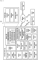
- Fig. 1 illustrates a block diagram of an electronic device 101 in a network environment 100 according to various embodiments.
- the electronic device 101 in the network environment 100 may communicate with an electronic device 102 via a first network 198 (e.g., a short-range wireless communication network), or an electronic device 104 or a server 108 via a second network 199 (e.g., a long-range wireless communication network).
- the electronic device 101 may communicate with the electronic device 104 via the server 108.
- the electronic device 101 may include a processor 120, memory 130, an input device 150, a sound output device 155, a display device 160, an audio module 170, a sensor module 176, an interface 177, a haptic module 179, a camera module 180, a power management module 188, a battery 189, a communication module 190, a subscriber identification module (SIM) 196, or an antenna module 197.
- at least one (e.g., the display device 160 or the camera module 180) of the components may be omitted from the electronic device 101, or one or more other components may be added in the electronic device 101.
- some of the components may be implemented as single integrated circuitry.
- the sensor module 176 e.g., a fingerprint sensor, an iris sensor, or an illuminance sensor
- the display device 160 e.g., a display
- an haptic module 179 e.g., a camera module 180
- a power management module 188 e.g., the display
- the processor 120 may execute, for example, software (e.g., a program 140) to control at least one other component (e.g., a hardware or software component) of the electronic device 101 coupled with the processor 120 and may perform various data processing or computation. According to one embodiment, as at least part of the data processing or computation, the processor 120 may load a command or data received from another component (e.g., the sensor module 176 or the communication module 190) in volatile memory 132, process the command or the data stored in the volatile memory 132, and store resulting data in non-volatile memory 134.
- software e.g., a program 140
- the processor 120 may load a command or data received from another component (e.g., the sensor module 176 or the communication module 190) in volatile memory 132, process the command or the data stored in the volatile memory 132, and store resulting data in non-volatile memory 134.
- the processor 120 may include a main processor 121 (e.g., a central processing unit (CPU) or an application processor (AP)), and an auxiliary processor 123 (e.g., a graphics processing unit (GPU), an image signal processor (ISP), a sensor hub processor, or a communication processor (CP)) that is operable independently from, or in conjunction with, the main processor 121.
- auxiliary processor 123 e.g., a graphics processing unit (GPU), an image signal processor (ISP), a sensor hub processor, or a communication processor (CP)
- the auxiliary processor 123 may be adapted to consume less power than the main processor 121, or to be specific to a specified function.
- the auxiliary processor 123 may be implemented as separate from, or as part of the main processor 121.
- the auxiliary processor 123 may control at least some of functions or states related to at least one component (e.g., the display device 160, the sensor module 176, or the communication module 190) among the components of the electronic device 101, instead of the main processor 121 while the main processor 121 is in an inactive (e.g., sleep) state, or together with the main processor 121 while the main processor 121 is in an active state (e.g., executing an application).
- the auxiliary processor 123 e.g., an image signal processor or a communication processor
- the memory 130 may store various data used by at least one component (e.g., the processor 120 or the sensor module 176) of the electronic device 101.
- the various data may include, for example, software (e.g., the program 140) and input data or output data for a command related thereto.
- the memory 130 may include the volatile memory 132 or the non-volatile memory 134.
- the program 140 may be stored in the memory 130 as software, and may include, for example, an operating system (OS) 142, middleware 144, or an application 146.
- OS operating system
- middleware middleware
- application application
- the input device 150 may receive a command or data to be used by other component (e.g., the processor 120) of the electronic device 101, from the outside (e.g., a user) of the electronic device 101.
- the input device 150 may include, for example, a microphone, a mouse, or a keyboard.
- the sound output device 155 may output sound signals to the outside of the electronic device 101.
- the sound output device 155 may include, for example, a speaker or a receiver.
- the speaker may be used for general purposes, such as playing multimedia or playing record, and the receiver may be used for incoming calls. According to an embodiment, the receiver may be implemented as separate from, or as part of the speaker.
- the display device 160 may visually provide information to the outside (e.g., a user) of the electronic device 101.
- the display device 160 may include, for example, a display, a hologram device, or a projector and control circuitry to control a corresponding one of the display, hologram device, and projector.
- the display device 160 may include touch circuitry adapted to detect a touch, or sensor circuitry (e.g., a pressure sensor) adapted to measure the intensity of force incurred by the touch.
- the audio module 170 may convert a sound into an electrical signal and vice versa. According to an embodiment, the audio module 170 may obtain the sound via the input device 150 or output the sound via the sound output device 155 or a headphone of an external electronic device (e.g., an electronic device 102) directly (e.g., wired) or wirelessly coupled with the electronic device 101.
- an external electronic device e.g., an electronic device 102
- directly e.g., wired
- the sensor module 176 may detect an operational state (e.g., power or temperature) of the electronic device 101 or an environmental state (e.g., a state of a user) external to the electronic device 101, and then generate an electrical signal or data value corresponding to the detected state.
- the sensor module 176 may include, for example, a gesture sensor, a gyro sensor, an atmospheric pressure sensor, a magnetic sensor, an acceleration sensor, a grip sensor, a proximity sensor, a color sensor, an infrared (IR) sensor, a biometric sensor, a temperature sensor, a humidity sensor, or an illuminance sensor.
- the interface 177 may support one or more specified protocols to be used for the electronic device 101 to be coupled with the external electronic device (e.g., the electronic device 102) directly (e.g., wired) or wirelessly.
- the interface 177 may include, for example, a high definition multimedia interface (HDMI), a universal serial bus (USB) interface, a secure digital (SD) card interface, or an audio interface.
- HDMI high definition multimedia interface
- USB universal serial bus
- SD secure digital
- a connecting terminal 178 may include a connector via which the electronic device 101 may be physically connected with the external electronic device (e.g., the electronic device 102).
- the connecting terminal 178 may include, for example, a HDMI connector, a USB connector, a SD card connector, or an audio connector (e.g., a headphone connector),
- the haptic module 179 may convert an electrical signal into a mechanical stimulus (e.g., a vibration or a movement) or electrical stimulus which may be recognized by a user via his tactile sensation or kinesthetic sensation.
- the haptic module 179 may include, for example, a motor, a piezoelectric element, or an electric stimulator.
- the camera module 180 may capture a still image or moving images.
- the camera module 180 may include one or more lenses, image sensors, image signal processors, or flashes.
- the power management module 188 may manage power supplied to the electronic device 101.
- the power management module 188 may be implemented as at least part of, for example, a power management integrated circuit (PMIC).
- PMIC power management integrated circuit
- the battery 189 may supply power to at least one component of the electronic device 101.
- the battery 189 may include, for example, a primary cell which is not rechargeable, a secondary cell which is rechargeable, or a fuel cell.
- the communication module 190 may support establishing a direct (e.g., wired) communication channel or a wireless communication channel between the electronic device 101 and the external electronic device (e.g., the electronic device 102, the electronic device 104, or the server 108) and performing communication via the established communication channel.
- the communication module 190 may include one or more communication processors that are operable independently from the processor 120 (e.g., the application processor (AP)) and supports a direct (e.g., wired) communication or a wireless communication.
- AP application processor
- the communication module 190 may include a wireless communication module 192 (e.g., a cellular communication module, a short-range wireless communication module, or a global navigation satellite system (GNSS) communication module) or a wired communication module 194 (e.g., a local area network (LAN) communication module or a power line communication (PLC) module).
- a wireless communication module 192 e.g., a cellular communication module, a short-range wireless communication module, or a global navigation satellite system (GNSS) communication module
- GNSS global navigation satellite system
- wired communication module 194 e.g., a local area network (LAN) communication module or a power line communication (PLC) module.
- LAN local area network
- PLC power line communication
- a corresponding one of these communication modules may communicate with the external electronic device via the first network 198 (e.g., a short-range communication network, such as BluetoothTM, wireless-fidelity (Wi-Fi) direct, or infrared data association (IrDA)) or the second network 199 (e.g., a long-range communication network, such as a cellular network, the Internet, or a computer network (e.g., LAN or wide area network (WAN)).
- the first network 198 e.g., a short-range communication network, such as BluetoothTM, wireless-fidelity (Wi-Fi) direct, or infrared data association (IrDA)
- the second network 199 e.g., a long-range communication network, such as a cellular network, the Internet, or a computer network (e.g., LAN or wide area network (WAN)
- These various types of communication modules may be implemented as a single component (e.g., a single chip), or may be implemented as multi components (e.
- the wireless communication module 192 may identify and authenticate the electronic device 101 in a communication network, such as the first network 198 or the second network 199, using subscriber information (e.g., international mobile subscriber identity (IMSI)) stored in the subscriber identification module 196.
- subscriber information e.g., international mobile subscriber identity (IMSI)
- the antenna module 197 may transmit or receive a signal or power to or from the outside (e.g., the external electronic device) of the electronic device 101.
- the antenna module 197 may include one or more antennas, and, therefrom, at least one antenna appropriate for a communication scheme used in the communication network, such as the first network 198 or the second network 199, may be selected, for example, by the communication module 190 (e.g., the wireless communication module 192).
- the signal or the power may then be transmitted or received between the communication module 190 and the external electronic device via the selected at least one antenna.
- At least some of the above-described components may be coupled mutually and communicate signals (e.g., commands or data) therebetween via an inter-peripheral communication scheme (e.g., a bus, general purpose input and output (GPIO), serial peripheral interface (SPI), or mobile industry processor interface (MIPI)).
- an inter-peripheral communication scheme e.g., a bus, general purpose input and output (GPIO), serial peripheral interface (SPI), or mobile industry processor interface (MIPI)
- commands or data may be transmitted or received between the electronic device 101 and the external electronic device 104 via the server 108 coupled with the second network 199.
- Each of the electronic devices 102 and 104 may be a device of a same type as, or a different type, from the electronic device 101.
- all or some of operations to be executed at the electronic device 101 may be executed at one or more of the external electronic devices 102, 104, or 108. For example, if the electronic device 101 should perform a function or a service automatically, or in response to a request from a user or another device, the electronic device 101, instead of, or in addition to, executing the function or the service, may request the one or more external electronic devices to perform at least part of the function or the service.
- the one or more external electronic devices receiving the request may perform at least part of the function or the service requested, or an additional function or an additional service related to the request, and transfer an outcome of the performing to the electronic device 101.
- the electronic device 101 may provide the outcome, with or without further processing of the outcome, as at least part of a reply to the request.
- a cloud computing, distributed computing, or client-server computing technology may be used, for example.
- the electronic device may be one of various types of electronic devices.
- the electronic devices may include, for example, a portable communication device (e.g., a smart phone), a computer device, a portable multimedia device, a portable medical device, a camera, a wearable device, or a home appliance. According to an embodiment of the disclosure, the electronic devices are not limited to those described above.
- each of such phrases as “A or B,” “at least one of A and B,” “at least one of A or B,” “A, B, or C,” “at least one of A, B, and C,” and “at least one of A, B, or C,” may include all possible combinations of the items enumerated together in a corresponding one of the phrases.
- such terms as “1st” and “2nd,” or “first” and “second” may be used to simply distinguish a corresponding component from another and does not limit the components in other aspect (e.g., importance or order).
- an element e.g., a first element
- the element may be coupled with the other element directly (e.g., wired), wirelessly, or via a third element.
- module may include a unit implemented in hardware, software, or firmware, and may interchangeably be used with other terms, for example, “logic,” “logic block,” “part,” or “circuitry”.
- a module may be a single integral component, or a minimum unit or part thereof, adapted to perform one or more functions.
- the module may be implemented in a form of an application-specific integrated circuit (ASIC).
- ASIC application-specific integrated circuit
- Various embodiments as set forth herein may be implemented as software (e.g., the program 140) including one or more instructions that are stored in a storage medium (e.g., internal memory 136 or external memory 138) that is readable by a machine (e.g., the electronic device 101).
- a processor e.g., the processor 120
- the machine e.g., the electronic device 101
- the one or more instructions may include a code generated by a complier or a code executable by an interpreter.
- the machine-readable storage medium may be provided in the form of a non-transitory storage medium.
- non-transitory simply means that the storage medium is a tangible device, and does not include a signal (e.g., an electromagnetic wave), but this term does not differentiate between where data is semi-permanently stored in the storage medium and where the data is temporarily stored in the storage medium.
- a method may be included and provided in a computer program product.
- the computer program product may be traded as a product between a seller and a buyer.
- the computer program product may be distributed in the form of a machine-readable storage medium (e.g., compact disc read only memory (CD-ROM)), or be distributed (e.g., downloaded or uploaded) online via an application store (e.g., Play StoreTM), or between two user devices (e.g., smart phones) directly. If distributed online, at least part of the computer program product may be temporarily generated or at least temporarily stored in the machine-readable storage medium, such as memory of the manufacturer's server, a server of the application store, or a relay server.
- CD-ROM compact disc read only memory
- an application store e.g., Play StoreTM
- two user devices e.g., smart phones
- each component e.g., a module or a program of the above-described components may include a single entity or multiple entities. According to various embodiments, one or more of the above-described components may be omitted, or one or more other components may be added. Alternatively, or additionally, a plurality of components (e.g., modules or programs) may be integrated into a single component. In such a case, according to various embodiments, the integrated component may still perform one or more functions of each of the plurality of components in the same or similar manner as they are performed by a corresponding one of the plurality of components before the integration.
- operations performed by the module, the program, or another component may be carried out sequentially, in parallel, repeatedly, or heuristically, or one or more of the operations may be executed in a different order or omitted, or one or more other operations may be added.
- FIG. 2 illustrates a diagram of a structure capable of detecting a battery status of an electronic device 101 according to various embodiments of the present disclosure.
- the electronic device 101 may include a housing 210, a battery chamber 220, and at least one of cavities 231 and 232.
- the housing 210 may include, for example, a bezel structure at a side portion thereof.
- the housing 210 may include at least one of vents 211 and 212.
- At least one of the vents 211 and 212 is an element for adjusting a difference in atmospheric pressure between the inside and the outside of the housing 210 of the electronic device 101 and may include a foreign substance prevention structure for preventing a foreign substance from being entered from the outside and for smooth air circulation.
- a foreign substance prevention structure contained in at least one of the vents 211 and 212 may include a membrane structure using waterproof fabric (e.g., GORE-TEX ® ).
- At least one of the vents 211 and 212 may be included in at least a portion of the housing 210 and may include, for example, a microphone hole, speaker hole, and connector hole (e.g., a universal serial bus (USB) and an earphone jack).
- a microphone hole e.g., a universal serial bus (USB) and an earphone jack.
- USB universal serial bus
- At least one of the vents 211 and 212 is an element for reducing a difference in atmospheric pressure between outdoor air and indoor air and may be punched or molded separately from the microphone hole, the speaker hole, and the connector hole upon producing.
- At least one of the vents 211 and 212 may be disposed adjacent to the camera module 180.
- At least one of the vents 211 and 212 may be connected to at least one of the cavities 231 and 232, respectively.
- At least one of the cavities 231 and 232 may be disposed inside the housing 210, and at least one of sensor modules 241 and 242 may be disposed on at least one of the cavities 231 and 232, respectively.
- At least one of the cavities 231 and 232 may include at least one wall forming a space.
- Each of at least one of the sensor modules 241 and 242 may include at least one gas sensor (shown in FIG. 3 ).
- At least one gas sensor may include a metal oxide (MOX) sensor. At least one gas sensor may be disposed in a partial space of at least one of the cavities 231 and 232 to measure a gas discharged from a battery 189 disposed within the housing 210 or air entered from the outside of an electronic device (not shown) through at least one of the vents 211 and 212.
- MOX metal oxide
- Each of at least one of the sensor modules 241 and 242 may further include an atmospheric pressure sensor (not shown).
- At least one of the cavities 231 and 232 may be partially connected to at least one of the vents 211 and 212, respectively and may be partially connected to a hole 250.
- the hole 250 may be disposed at least partially in the battery chamber 220.
- the hole 250 disposed at least partially in the battery chamber 220 may be a passage of a gas discharged from a battery 189.
- the hole 250 may be punched or shaped upon producing the electronic device 101.
- At least one of the cavities 231 and 232 may collect a gas discharged from the hole 250 to enable at least one gas sensor to analyze the collected gas and provide a space to discharge the collected gas to the outside through at least one of the vents 211 and 212.
- the battery chamber 220 may be disposed inside or in at least a portion of the housing 210, and the battery chamber 220 may be separated from at least a portion of the battery 189 to protect the battery 189.
- the battery chamber 220 may dispose the battery 189 on an inner space and separate the battery 189 from other devices included in the electronic device 101.
- the battery chamber 220 may be a portion of the housing 210 of the electronic device 101 configured with a bracket.
- the battery chamber 220 may include at least one wall forming a space.
- the battery chamber 220 may include a hole 250 in at least a portion thereof, and a gas discharged from the battery 189 through the hole 250 may be transferred to the at least one of the cavities 231 and 232.
- the hole 250, at least one of the cavities 231 and 232, and at least one of the vents 211 and 212 included in at least a portion of the battery chamber 220 may have a duct structure that can discharge a gas discharged from the battery 189 to the outside.
- the hole 250 or at least one of the vents 211 and 212 may be referred to as an opening.
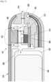
- FIG. 3 illustrates a diagram of a structure capable of detecting a battery status of an electronic device 101 according to various embodiments of the present disclosure.
- the electronic device 101 may include a housing 210, battery chamber 220, and cavity 231.
- the housing 210 may include electronic components, a battery 189, and a gas sensor 311 related to the electronic device 101 therein.
- the housing 210 may include at least one of the vents 212 and 213.
- At least one of the vents 212 and 213 is an element for adjusting a difference in atmospheric pressure between the inside and the outside of the housing 201 of the electronic device 101 and may include a foreign substance prevention structure 330 for preventing a foreign substance from being entered from the outside and for smooth air communication.
- the foreign substance prevention structure 330 included in at least one of the vents 212 and 213 may include a membrane structure using waterproof fabric (e.g., GORE-TEX ® ), and the like.
- At least one of the vents 212 and 213 may be formed (or disposed) in a portion of the housing 210 and may include, for example, a microphone hole, speaker hole, and connector hole (e.g., USB and earphone jack).
- At least one of the vents 212 and 213 is an element for reducing a difference in atmospheric pressure between outdoor air and indoor air and may be punched or shaped in a portion of the housing 210 separately from the microphone hole, the speaker hole, and the connector hole upon producing.
- At least one of the vents 212 and 213 may be disposed adjacent to a camera module 180.
- the first vent 212 may be disposed through a portion of the housing 210 adjacent to the camera module 180 or may be formed in at least a portion of the housing 210 including the camera module 180.
- the second vent 213 may include, for example, a microphone hole, speaker hole, and connector hole (e.g., USB and earphone jack).
- the second vent 213 may be formed (or disposed) in the form of, for example, a microphone hole, speaker hole, and connector hole (e.g., USB and earphone jack) in a portion of the housing 210. At least one of the vents 212 and 213 may be connected to the cavity 231.
- the cavity 231 may be disposed inside the housing 210, and a sensor module (e.g., 241 of FIG. 2 ) may be disposed in at least one cavity 231.
- the sensor module (e.g., 241 of FIG. 2 ) may include a gas sensor 311 and/or an atmospheric pressure sensor 312.
- the gas sensor 311 may detect and analyze a gas discharged from the battery 189.
- the gas sensor 311 may transfer the detected and analyzed gas information to the processor 120.
- the atmospheric pressure sensor 312 may measure an atmospheric pressure using air outside the housing 210 entered through at least one of the vents 212 and 213.
- the gas sensor 311 may be a metal oxide (MOX) sensor.
- the gas sensor 311 may be disposed in a partial space of the cavity 231 to measure components contained in a gas discharged from the battery 189 disposed inside the housing 210 or air entered from the outside of the electronic device 101 through at least one of the vents 212 and 213.
- a portion of the cavity 231 may be connected to at least one of the vents 212 and 213 and may be connected to a hole 250.
- the hole 250 may be formed in at least a portion of the battery chamber 220.
- the hole 250 formed in at least a portion of the battery chamber 220 may be a passage for the gas discharged from the battery 189.
- the hole 250 may be punched or shaped in at least a portion of the housing 210 upon producing the electronic device 101.
- the cavity 231 may collect a gas discharged from the hole 250 to enable at least one gas sensor 311 to analyze the collected gas and provide a space to enable the collected gas to be discharged outside through at least one of the vents 212 and 213.
- the cavity 231 may include at least one wall forming a space.
- the battery chamber 220 may be disposed inside the housing 210 or in at least a portion of the housing 210 and may be separated from at least a portion of the battery 189 to protect the battery 189.
- the battery chamber 220 may dispose the battery 189 on an inner space and may be separated from other devices included in the electronic device 101.
- the battery chamber 220 may be a portion of the housing 210 of the electronic device 101 configured with a bracket.
- the battery chamber 220 may include at least one wall forming a space.
- the battery chamber 220 may include a hole 250 in at least a portion thereof and may transfer a gas discharged from the battery 189 to the cavity 231 through the hole 250.
- the hole 250 and the cavity 231 in the battery chamber 220 and at least a portion of the vents 212 and 213 may form a duct structure that may discharge a gas discharged from the battery 189 to the outside.
- the hole 250 or at least one of the vents 212 and 213 may be referred to as an opening.
- FIG. 4 illustrates a flowchart of a method of detecting a battery status according to various embodiments of the present disclosure.
- the gas sensor (e.g., 311 of FIG. 3 ) of the electronic device 101 may detect whether a gas is generated.
- the processor (e.g., 120 of FIG. 1 ) of the electronic device 101 may receive gas information data from the gas sensor (e.g., 311 of FIG. 3 ).
- the operation of receiving gas information data may be, for example, an operation of receiving information on a type and concentration of the gas contained in the gas.
- the processor e.g., 120 of FIG. 1
- the processor may analyze gas information using gas information data.
- the gas sensor e.g., 311 of FIG. 3
- the electronic device 101 may analyze gas information using gas information data.
- the operation of analyzing gas information may be an operation of analyzing information on a type and concentration of the gas.
- the processor e.g., 120 of FIG. 1
- the processor may determine whether a specific gas is a reference value or more.
- the gas sensor (e.g., 311 of FIG. 3 ) of the electronic device 101 may determine whether a specific gas is a reference value or more.
- operation 407 if the specific gas is less than a reference value, the process continues in operation 401.
- the specific gas may be a gas discharged from the battery 189 and may be a hydrogen (H2) gas or an organic compound gas discharged at a high concentration when the battery 189 is in an abnormal state, and a reference value thereof may be a specific concentration.
- the specific concentration may be arbitrarily determined and may be a concentration close to an explosion threshold.
- the electronic device 101 may determine an abnormal operation of the battery 189 under the control of the processor (e.g., 120 of FIG. 1 ).
- the electronic device 101 may perform a designated operation under the control of the processor (e.g., 120 of FIG. 1 ).
- the designated operation may notify a user of an abnormal operation of the battery 189 and update log information.
- the operation of notifying the user of an abnormal operation of the battery 189 may be, for example, an operation of displaying a message related to abnormality of the battery 189 on the display device 160.
- the operation of updating log information may include an operation of performing a photographing operation through the camera module 180. As illustrated in FIGS. 2 and 3 , when at least one vent 212 is disposed adjacent to the camera module 180, the gas passes over a window or an image sensor of the camera module 180. When the electronic device 101 is exploded or ignited because of a gas having a specific concentration or more, a combustion gas or an ignition scene may be photographed through the camera module 180. The captured image may be updated as log information.
- the log information may be a concentration and type of a gas detected when an abnormal symptom is detected, a gas detection time, and the serial number of the electronic device 101.
- the operation of updating log information may include at least one of an operation of storing log information in the memory 130 of the electronic device 101 and an operation of transmitting log information to the server (e.g., 108 of FIG. 1 ) through the communication module 190.
- FIG. 5 illustrates a graph of a resistance value of a gas that can be detected by an electronic device 101 according to various embodiments of the present disclosure.
- X-axis is a concentration of a gas
- Y-axis is a resistance value. The higher the gas concentration, the lower the resistance value.
- the electronic device 101 may store a resistance value according to the concentration in the memory 130 as look-up data.
- the processor e.g., 120 of FIG. 1
- the gas sensor e.g., 311 of FIG. 3
- FIG. 4 may perform the operation of FIG. 4 using the look-up data, which are a resistance value according to the concentration stored in the memory 130 of the electronic device 101.
- FIG. 6 illustrates a diagram of an operation in which an electronic device 101 notifies a user of an abnormal operation of a battery 189 according to various embodiments of the present disclosure.
- the display device 160 of the electronic device 101 may display an user interface (UI) related to gas leakage to a user of the electronic device 101 under the control of the processor 120.
- UI user interface
- the UI may include a warning such as "Turn off power because abnormality is detected in a battery” or "Please turn off power for more safe use and check at a nearby service center.”
- the processor 120 may transmit the serial number of the electronic device 101 and detected gas related information to, for example, a server (e.g., the server 108 of FIG. 1 ) of a service center through the network (e.g., the second network 199 of FIG. 1 ) and turn off power of the electronic device 101, thereby preventing an accident to be caused by the battery 189.
- a server e.g., the server 108 of FIG. 1
- the network e.g., the second network 199 of FIG. 1
- An electronic device may be various types of devices.
- the electronic device may include, for example, at least one of a portable communication device (e.g., a smart phone), computer device, portable multimedia device, portable medical device, camera, wearable device, and home appliance.
- a portable communication device e.g., a smart phone
- computer device e.g., a smart phone
- portable multimedia device e.g., portable medical device
- camera e.g., a smart phone
- wearable device e.g., a smart phone
- first and second used in this document may indicate corresponding components regardless of order or importance, and such an expression is used for distinguishing a component from another component and does not limit corresponding components.
- a component e.g., a first component
- another component e.g., a second component
- the component may be directly connected to the another component or may be connected to the another component through another component (e.g., a third component).
- a term "module” used in this document includes a unit configured with hardware, software, or firmware and may be interchangeably used with a term such as a logic, logic block, component, or circuit.
- the module may be an integrally configured component or a minimum unit that performs at least one function or a portion thereof.
- the module may be configured with an application-specific integrated circuit (ASIC).
- ASIC application-specific integrated circuit
- Various embodiments of this document may implemented with software (e.g., the program 140) including instructions stored on a machine (e.g., a computer)-readable storage medium (e.g., the internal memory 136 or the external memory 138).
- the machine is a device that calls a stored instruction from a storage medium and that may operate according to the called instruction and may include an electronic device (e.g., the electronic device 101) according to disclosed embodiments.
- the command When the command is executed by a processor (e.g., the processor 120), the processor may perform a function corresponding to the command directly or using other components under the control of the processor.
- the command may include a code generated or executed by a compiler or an interpreter.
- the machine readable storage medium may be provided in a format of a non-transitory storage medium.
- non-transitory means that a storage medium does not include a signal and is tangible and does not divide that data are semi-permanently or temporarily stored at a storage medium.
- a method according to various embodiments disclosed in this document may be included and provided in a computer program product.
- the computer program product may be traded as a product between a seller and a buyer.
- the computer program product may be distributed in online in a form of a machine readable storage medium (e.g., compact disc read only memory (CD-ROM) or through an application store (e.g., play storeTM).
- a machine readable storage medium e.g., compact disc read only memory (CD-ROM) or through an application store (e.g., play storeTM).
- at least a portion of the computer program product may be at least temporarily stored or temporarily generated in a storage medium such as a server of a manufacturer, a server of an application store, or a memory of a relay server.
- Each of components may be configured with a single entity or a plurality of entities, and some subcomponents of the foregoing subcomponents may be omitted or other subcomponents may be further included in various embodiments.
- some components e.g., modules or programs
- operations performed by a module, a program, or another component may be sequentially, parallelly, repeatedly, or heuristically executed, at least some operation may be executed in different order or omitted, or another operation may be added.
- An electronic device 101 can detect in real time gas leakage of a battery 189 occurring by exposure to a high temperature or a generated heat and control a status of the battery 189, thereby preventing a safety accident by the battery 189.
- the electronic device 101 can warn a user and obtain log information about the abnormal battery event.
Landscapes
- Engineering & Computer Science (AREA)
- Chemical & Material Sciences (AREA)
- Chemical Kinetics & Catalysis (AREA)
- Electrochemistry (AREA)
- General Chemical & Material Sciences (AREA)
- Manufacturing & Machinery (AREA)
- Microelectronics & Electronic Packaging (AREA)
- Physics & Mathematics (AREA)
- General Physics & Mathematics (AREA)
- Signal Processing (AREA)
- Theoretical Computer Science (AREA)
- Human Computer Interaction (AREA)
- General Engineering & Computer Science (AREA)
- Environmental & Geological Engineering (AREA)
- Computer Networks & Wireless Communication (AREA)
- Battery Mounting, Suspending (AREA)
- Power Sources (AREA)
- Telephone Function (AREA)
- Examining Or Testing Airtightness (AREA)
- Investigating Or Analyzing Materials By The Use Of Electric Means (AREA)
- Charge And Discharge Circuits For Batteries Or The Like (AREA)
- Secondary Cells (AREA)
Description
- Various embodiments of the present disclosure relate to an electronic device and a method of detecting a status of a battery thereof, and more particularly, to an electronic device and a method of detecting a status of a battery thereof using a sensor and notifying a user of the battery status.
- Use of various electronic devices such as a smart phone, tablet personal computer (PC), portable multimedia player (PMP), personal digital assistant (PDA), laptop PC, wrist watch, and wearable device such as a head-mounted display (HMD) has been increased, and various functions may be performed through various electronic devices.
- Various electronic devices may include batteries that provide power to perform various functions.
- As electronic devices perform various functions, a capacity and rapid charge of a battery are becoming important problems. The battery may have different types and different environmental characteristics according to the use purpose of each of the electronic devices. As an electrolyte is decomposed because of overcharge, exposure to a high temperature, and an internal short circuit, the battery may generate a gas or may be ruptured.
-
US2017318135 describes a mobile terminal including a terminal body provided with a case having at least one hole; a gas sensor module disposed near the case, and configured to sense specific gas by air introduced through the hole; and a controller configured to set a type of gas to be sensed based on an activated specific function, and to control the gas sensor module to sense the gas. - The present disclosure provides a structure of an electronic device that can detect a gas generated in a battery using a sensor.
- The present disclosure further provides a method of controlling an electronic device by detecting a gas generated in a battery.
- The present disclosure further provides an electronic device that can provide log information by detecting an abnormal event of a battery.
- In accordance with an aspect of the present disclosure, an electronic device includes features defined in the appended independent device claim.
- Definitions for certain words and phrases are provided throughout this patent document, those of ordinary skill in the art should understand that in many, if not most instances, such definitions apply to prior, as well as future uses of such defined words and phrases.
- An electronic device according to various embodiments of the present disclosure can detect in real time gas leakage of a battery occurring by exposure to a high temperature or a generated heat and control a status of the battery, thereby preventing a safety accident by the battery.
- According to various embodiments of the present disclosure, by discharging a gas generated in the battery to the outside of the electronic device, stability of the battery to be used by the electronic device can be secured.
- According to various embodiments of the present disclosure, when an abnormal event occurs in a battery, the electronic device can warn a user and obtain log information about the abnormal battery event.
- Although embodiments of the present disclosure have been described in detail hereinabove, it should be clearly understood that many variations and modifications of the basic inventive concepts herein described, which may appear to those skilled in the art, will still fall within the scope of the embodiments of the present disclosure as defined in the appended claims.
- The objects, features, and advantages of the present disclosure will be more apparent from the following detailed description in conjunction with the accompanying drawings, in which:
-
FIG. 1 illustrates a block diagram of a configuration of an electronic device in a network environment according to various embodiments; -
FIG. 2 illustrates a diagram of a structure capable of detecting a battery status of an electronic device according to various embodiments of the present disclosure; -
FIG. 3 illustrates a diagram of a structure capable of detecting a battery status of an electronic device according to various embodiments of the present disclosure; -
FIG. 4 illustrates a flowchart of a method of detecting a battery status according to various embodiments of the present disclosure; -
FIG. 5 illustrates a graph of a resistance value of a gas that can be detected by an electronic device according to various embodiments of the present disclosure; and -
FIG. 6 illustrates a diagram of an operation in which an electronic device notifies a user of a battery abnormal operation according to various embodiments of the present disclosure. -
FIGS. 1 through 6 , discussed below, and the various embodiments used to describe the principles of the present disclosure in this patent document are by way of illustration only and should not be construed in any way to limit the scope of the disclosure. Those skilled in the art will understand that the principles of the present disclosure may be implemented in any suitably arranged system or device. -
Fig. 1 illustrates a block diagram of anelectronic device 101 in anetwork environment 100 according to various embodiments. Referring toFig. 1 , theelectronic device 101 in thenetwork environment 100 may communicate with anelectronic device 102 via a first network 198 (e.g., a short-range wireless communication network), or anelectronic device 104 or aserver 108 via a second network 199 (e.g., a long-range wireless communication network). According to an embodiment, theelectronic device 101 may communicate with theelectronic device 104 via theserver 108. According to an embodiment, theelectronic device 101 may include aprocessor 120,memory 130, aninput device 150, asound output device 155, adisplay device 160, anaudio module 170, asensor module 176, aninterface 177, ahaptic module 179, acamera module 180, apower management module 188, abattery 189, acommunication module 190, a subscriber identification module (SIM) 196, or anantenna module 197. In some embodiments, at least one (e.g., thedisplay device 160 or the camera module 180) of the components may be omitted from theelectronic device 101, or one or more other components may be added in theelectronic device 101. In some embodiments, some of the components may be implemented as single integrated circuitry. For example, the sensor module 176 (e.g., a fingerprint sensor, an iris sensor, or an illuminance sensor) may be implemented as embedded in the display device 160 (e.g., a display). - The
processor 120 may execute, for example, software (e.g., a program 140) to control at least one other component (e.g., a hardware or software component) of theelectronic device 101 coupled with theprocessor 120 and may perform various data processing or computation. According to one embodiment, as at least part of the data processing or computation, theprocessor 120 may load a command or data received from another component (e.g., thesensor module 176 or the communication module 190) involatile memory 132, process the command or the data stored in thevolatile memory 132, and store resulting data innon-volatile memory 134. According to an embodiment, theprocessor 120 may include a main processor 121 (e.g., a central processing unit (CPU) or an application processor (AP)), and an auxiliary processor 123 (e.g., a graphics processing unit (GPU), an image signal processor (ISP), a sensor hub processor, or a communication processor (CP)) that is operable independently from, or in conjunction with, themain processor 121. Additionally, or alternatively, theauxiliary processor 123 may be adapted to consume less power than themain processor 121, or to be specific to a specified function. Theauxiliary processor 123 may be implemented as separate from, or as part of themain processor 121. - The
auxiliary processor 123 may control at least some of functions or states related to at least one component (e.g., thedisplay device 160, thesensor module 176, or the communication module 190) among the components of theelectronic device 101, instead of themain processor 121 while themain processor 121 is in an inactive (e.g., sleep) state, or together with themain processor 121 while themain processor 121 is in an active state (e.g., executing an application). According to an embodiment, the auxiliary processor 123 (e.g., an image signal processor or a communication processor) may be implemented as part of another component (e.g., thecamera module 180 or the communication module 190) functionally related to theauxiliary processor 123. - The
memory 130 may store various data used by at least one component (e.g., theprocessor 120 or the sensor module 176) of theelectronic device 101. The various data may include, for example, software (e.g., the program 140) and input data or output data for a command related thereto. Thememory 130 may include thevolatile memory 132 or thenon-volatile memory 134. - The
program 140 may be stored in thememory 130 as software, and may include, for example, an operating system (OS) 142,middleware 144, or anapplication 146. - The
input device 150 may receive a command or data to be used by other component (e.g., the processor 120) of theelectronic device 101, from the outside (e.g., a user) of theelectronic device 101. Theinput device 150 may include, for example, a microphone, a mouse, or a keyboard. - The
sound output device 155 may output sound signals to the outside of theelectronic device 101. Thesound output device 155 may include, for example, a speaker or a receiver. The speaker may be used for general purposes, such as playing multimedia or playing record, and the receiver may be used for incoming calls. According to an embodiment, the receiver may be implemented as separate from, or as part of the speaker. - The
display device 160 may visually provide information to the outside (e.g., a user) of theelectronic device 101. Thedisplay device 160 may include, for example, a display, a hologram device, or a projector and control circuitry to control a corresponding one of the display, hologram device, and projector. According to an embodiment, thedisplay device 160 may include touch circuitry adapted to detect a touch, or sensor circuitry (e.g., a pressure sensor) adapted to measure the intensity of force incurred by the touch. - The
audio module 170 may convert a sound into an electrical signal and vice versa. According to an embodiment, theaudio module 170 may obtain the sound via theinput device 150 or output the sound via thesound output device 155 or a headphone of an external electronic device (e.g., an electronic device 102) directly (e.g., wired) or wirelessly coupled with theelectronic device 101. - The
sensor module 176 may detect an operational state (e.g., power or temperature) of theelectronic device 101 or an environmental state (e.g., a state of a user) external to theelectronic device 101, and then generate an electrical signal or data value corresponding to the detected state. According to an embodiment, thesensor module 176 may include, for example, a gesture sensor, a gyro sensor, an atmospheric pressure sensor, a magnetic sensor, an acceleration sensor, a grip sensor, a proximity sensor, a color sensor, an infrared (IR) sensor, a biometric sensor, a temperature sensor, a humidity sensor, or an illuminance sensor. - The
interface 177 may support one or more specified protocols to be used for theelectronic device 101 to be coupled with the external electronic device (e.g., the electronic device 102) directly (e.g., wired) or wirelessly. According to an embodiment, theinterface 177 may include, for example, a high definition multimedia interface (HDMI), a universal serial bus (USB) interface, a secure digital (SD) card interface, or an audio interface. - A connecting
terminal 178 may include a connector via which theelectronic device 101 may be physically connected with the external electronic device (e.g., the electronic device 102). According to an embodiment, the connectingterminal 178 may include, for example, a HDMI connector, a USB connector, a SD card connector, or an audio connector (e.g., a headphone connector), - The
haptic module 179 may convert an electrical signal into a mechanical stimulus (e.g., a vibration or a movement) or electrical stimulus which may be recognized by a user via his tactile sensation or kinesthetic sensation. According to an embodiment, thehaptic module 179 may include, for example, a motor, a piezoelectric element, or an electric stimulator. - The
camera module 180 may capture a still image or moving images. According to an embodiment, thecamera module 180 may include one or more lenses, image sensors, image signal processors, or flashes. - The
power management module 188 may manage power supplied to theelectronic device 101. According to one embodiment, thepower management module 188 may be implemented as at least part of, for example, a power management integrated circuit (PMIC). - The
battery 189 may supply power to at least one component of theelectronic device 101. According to an embodiment, thebattery 189 may include, for example, a primary cell which is not rechargeable, a secondary cell which is rechargeable, or a fuel cell. - The
communication module 190 may support establishing a direct (e.g., wired) communication channel or a wireless communication channel between theelectronic device 101 and the external electronic device (e.g., theelectronic device 102, theelectronic device 104, or the server 108) and performing communication via the established communication channel. Thecommunication module 190 may include one or more communication processors that are operable independently from the processor 120 (e.g., the application processor (AP)) and supports a direct (e.g., wired) communication or a wireless communication. According to an embodiment, thecommunication module 190 may include a wireless communication module 192 (e.g., a cellular communication module, a short-range wireless communication module, or a global navigation satellite system (GNSS) communication module) or a wired communication module 194 (e.g., a local area network (LAN) communication module or a power line communication (PLC) module). A corresponding one of these communication modules may communicate with the external electronic device via the first network 198 (e.g., a short-range communication network, such as BluetoothTM, wireless-fidelity (Wi-Fi) direct, or infrared data association (IrDA)) or the second network 199 (e.g., a long-range communication network, such as a cellular network, the Internet, or a computer network (e.g., LAN or wide area network (WAN)). These various types of communication modules may be implemented as a single component (e.g., a single chip), or may be implemented as multi components (e.g., multi chips) separate from each other. Thewireless communication module 192 may identify and authenticate theelectronic device 101 in a communication network, such as thefirst network 198 or thesecond network 199, using subscriber information (e.g., international mobile subscriber identity (IMSI)) stored in thesubscriber identification module 196. - The
antenna module 197 may transmit or receive a signal or power to or from the outside (e.g., the external electronic device) of theelectronic device 101. According to an embodiment, theantenna module 197 may include one or more antennas, and, therefrom, at least one antenna appropriate for a communication scheme used in the communication network, such as thefirst network 198 or thesecond network 199, may be selected, for example, by the communication module 190 (e.g., the wireless communication module 192). The signal or the power may then be transmitted or received between thecommunication module 190 and the external electronic device via the selected at least one antenna. - At least some of the above-described components may be coupled mutually and communicate signals (e.g., commands or data) therebetween via an inter-peripheral communication scheme (e.g., a bus, general purpose input and output (GPIO), serial peripheral interface (SPI), or mobile industry processor interface (MIPI)).
- According to an embodiment, commands or data may be transmitted or received between the
electronic device 101 and the externalelectronic device 104 via theserver 108 coupled with thesecond network 199. Each of theelectronic devices electronic device 101. According to an embodiment, all or some of operations to be executed at theelectronic device 101 may be executed at one or more of the externalelectronic devices electronic device 101 should perform a function or a service automatically, or in response to a request from a user or another device, theelectronic device 101, instead of, or in addition to, executing the function or the service, may request the one or more external electronic devices to perform at least part of the function or the service. The one or more external electronic devices receiving the request may perform at least part of the function or the service requested, or an additional function or an additional service related to the request, and transfer an outcome of the performing to theelectronic device 101. Theelectronic device 101 may provide the outcome, with or without further processing of the outcome, as at least part of a reply to the request. To that end, a cloud computing, distributed computing, or client-server computing technology may be used, for example. - The electronic device according to various embodiments may be one of various types of electronic devices. The electronic devices may include, for example, a portable communication device (e.g., a smart phone), a computer device, a portable multimedia device, a portable medical device, a camera, a wearable device, or a home appliance. According to an embodiment of the disclosure, the electronic devices are not limited to those described above.
- It should be appreciated that various embodiments of the present disclosure and the terms used therein are not intended to limit the technological features set forth herein to particular embodiments and include various changes, equivalents, or replacements for a corresponding embodiment. With regard to the description of the drawings, similar reference numerals may be used to refer to similar or related elements. It is to be understood that a singular form of a noun corresponding to an item may include one or more of the things, unless the relevant context clearly indicates otherwise. As used herein, each of such phrases as "A or B," "at least one of A and B," "at least one of A or B," "A, B, or C," "at least one of A, B, and C," and "at least one of A, B, or C," may include all possible combinations of the items enumerated together in a corresponding one of the phrases. As used herein, such terms as "1st" and "2nd," or "first" and "second" may be used to simply distinguish a corresponding component from another and does not limit the components in other aspect (e.g., importance or order). It is to be understood that if an element (e.g., a first element) is referred to, with or without the term "operatively" or "communicatively", as "coupled with," "coupled to," "connected with," or "connected to" another element (e.g., a second element), it means that the element may be coupled with the other element directly (e.g., wired), wirelessly, or via a third element.
- As used herein, the term "module" may include a unit implemented in hardware, software, or firmware, and may interchangeably be used with other terms, for example, "logic," "logic block," "part," or "circuitry". A module may be a single integral component, or a minimum unit or part thereof, adapted to perform one or more functions. For example, according to an embodiment, the module may be implemented in a form of an application-specific integrated circuit (ASIC).
- Various embodiments as set forth herein may be implemented as software (e.g., the program 140) including one or more instructions that are stored in a storage medium (e.g.,
internal memory 136 or external memory 138) that is readable by a machine (e.g., the electronic device 101). For example, a processor (e.g., the processor 120) of the machine (e.g., the electronic device 101) may invoke at least one of the one or more instructions stored in the storage medium, and execute it, with or without using one or more other components under the control of the processor. This allows the machine to be operated to perform at least one function according to the at least one instruction invoked. The one or more instructions may include a code generated by a complier or a code executable by an interpreter. The machine-readable storage medium may be provided in the form of a non-transitory storage medium. Wherein, the term "non-transitory" simply means that the storage medium is a tangible device, and does not include a signal (e.g., an electromagnetic wave), but this term does not differentiate between where data is semi-permanently stored in the storage medium and where the data is temporarily stored in the storage medium. - According to an embodiment, a method according to various embodiments of the disclosure may be included and provided in a computer program product. The computer program product may be traded as a product between a seller and a buyer. The computer program product may be distributed in the form of a machine-readable storage medium (e.g., compact disc read only memory (CD-ROM)), or be distributed (e.g., downloaded or uploaded) online via an application store (e.g., Play StoreTM), or between two user devices (e.g., smart phones) directly. If distributed online, at least part of the computer program product may be temporarily generated or at least temporarily stored in the machine-readable storage medium, such as memory of the manufacturer's server, a server of the application store, or a relay server.
- According to various embodiments, each component (e.g., a module or a program) of the above-described components may include a single entity or multiple entities. According to various embodiments, one or more of the above-described components may be omitted, or one or more other components may be added. Alternatively, or additionally, a plurality of components (e.g., modules or programs) may be integrated into a single component. In such a case, according to various embodiments, the integrated component may still perform one or more functions of each of the plurality of components in the same or similar manner as they are performed by a corresponding one of the plurality of components before the integration. According to various embodiments, operations performed by the module, the program, or another component may be carried out sequentially, in parallel, repeatedly, or heuristically, or one or more of the operations may be executed in a different order or omitted, or one or more other operations may be added.
-
FIG. 2 illustrates a diagram of a structure capable of detecting a battery status of anelectronic device 101 according to various embodiments of the present disclosure. - According to various embodiments, the
electronic device 101 may include ahousing 210, abattery chamber 220, and at least one ofcavities - The
housing 210 may include, for example, a bezel structure at a side portion thereof. Thehousing 210 may include at least one ofvents - At least one of the
vents housing 210 of theelectronic device 101 and may include a foreign substance prevention structure for preventing a foreign substance from being entered from the outside and for smooth air circulation. A foreign substance prevention structure contained in at least one of thevents - At least one of the
vents housing 210 and may include, for example, a microphone hole, speaker hole, and connector hole (e.g., a universal serial bus (USB) and an earphone jack). - At least one of the
vents - At least one of the
vents camera module 180. - At least one of the
vents cavities - At least one of the
cavities housing 210, and at least one ofsensor modules cavities - At least one of the
cavities - Each of at least one of the
sensor modules FIG. 3 ). - At least one gas sensor may include a metal oxide (MOX) sensor. At least one gas sensor may be disposed in a partial space of at least one of the
cavities battery 189 disposed within thehousing 210 or air entered from the outside of an electronic device (not shown) through at least one of thevents - Each of at least one of the
sensor modules - At least one of the
cavities vents hole 250. - The
hole 250 may be disposed at least partially in thebattery chamber 220. Thehole 250 disposed at least partially in thebattery chamber 220 may be a passage of a gas discharged from abattery 189. Thehole 250 may be punched or shaped upon producing theelectronic device 101. - At least one of the
cavities hole 250 to enable at least one gas sensor to analyze the collected gas and provide a space to discharge the collected gas to the outside through at least one of thevents - The
battery chamber 220 may be disposed inside or in at least a portion of thehousing 210, and thebattery chamber 220 may be separated from at least a portion of thebattery 189 to protect thebattery 189. - The
battery chamber 220 may dispose thebattery 189 on an inner space and separate thebattery 189 from other devices included in theelectronic device 101. - The
battery chamber 220 may be a portion of thehousing 210 of theelectronic device 101 configured with a bracket. - The
battery chamber 220 may include at least one wall forming a space. - The
battery chamber 220 may include ahole 250 in at least a portion thereof, and a gas discharged from thebattery 189 through thehole 250 may be transferred to the at least one of thecavities - The
hole 250, at least one of thecavities vents battery chamber 220 may have a duct structure that can discharge a gas discharged from thebattery 189 to the outside. Thehole 250 or at least one of thevents -
FIG. 3 illustrates a diagram of a structure capable of detecting a battery status of anelectronic device 101 according to various embodiments of the present disclosure. - According to various embodiments, the
electronic device 101 may include ahousing 210,battery chamber 220, andcavity 231. - The
housing 210 may include electronic components, abattery 189, and agas sensor 311 related to theelectronic device 101 therein. Thehousing 210 may include at least one of thevents - At least one of the
vents electronic device 101 and may include a foreignsubstance prevention structure 330 for preventing a foreign substance from being entered from the outside and for smooth air communication. The foreignsubstance prevention structure 330 included in at least one of thevents - At least one of the
vents housing 210 and may include, for example, a microphone hole, speaker hole, and connector hole (e.g., USB and earphone jack). - At least one of the
vents housing 210 separately from the microphone hole, the speaker hole, and the connector hole upon producing. - At least one of the
vents camera module 180. - For example, the
first vent 212 may be disposed through a portion of thehousing 210 adjacent to thecamera module 180 or may be formed in at least a portion of thehousing 210 including thecamera module 180. - The
second vent 213 may include, for example, a microphone hole, speaker hole, and connector hole (e.g., USB and earphone jack). - The
second vent 213 may be formed (or disposed) in the form of, for example, a microphone hole, speaker hole, and connector hole (e.g., USB and earphone jack) in a portion of thehousing 210. At least one of thevents cavity 231. - The
cavity 231 may be disposed inside thehousing 210, and a sensor module (e.g., 241 ofFIG. 2 ) may be disposed in at least onecavity 231. The sensor module (e.g., 241 ofFIG. 2 ) may include agas sensor 311 and/or anatmospheric pressure sensor 312. Thegas sensor 311 may detect and analyze a gas discharged from thebattery 189. Thegas sensor 311 may transfer the detected and analyzed gas information to theprocessor 120. Theatmospheric pressure sensor 312 may measure an atmospheric pressure using air outside thehousing 210 entered through at least one of thevents - The
gas sensor 311 may be a metal oxide (MOX) sensor. Thegas sensor 311 may be disposed in a partial space of thecavity 231 to measure components contained in a gas discharged from thebattery 189 disposed inside thehousing 210 or air entered from the outside of theelectronic device 101 through at least one of thevents - A portion of the
cavity 231 may be connected to at least one of thevents hole 250. - The
hole 250 may be formed in at least a portion of thebattery chamber 220. Thehole 250 formed in at least a portion of thebattery chamber 220 may be a passage for the gas discharged from thebattery 189. Thehole 250 may be punched or shaped in at least a portion of thehousing 210 upon producing theelectronic device 101. - The
cavity 231 may collect a gas discharged from thehole 250 to enable at least onegas sensor 311 to analyze the collected gas and provide a space to enable the collected gas to be discharged outside through at least one of thevents - The
cavity 231 may include at least one wall forming a space. - The
battery chamber 220 may be disposed inside thehousing 210 or in at least a portion of thehousing 210 and may be separated from at least a portion of thebattery 189 to protect thebattery 189. - The
battery chamber 220 may dispose thebattery 189 on an inner space and may be separated from other devices included in theelectronic device 101. - The
battery chamber 220 may be a portion of thehousing 210 of theelectronic device 101 configured with a bracket. - The
battery chamber 220 may include at least one wall forming a space. - The
battery chamber 220 may include ahole 250 in at least a portion thereof and may transfer a gas discharged from thebattery 189 to thecavity 231 through thehole 250. - The
hole 250 and thecavity 231 in thebattery chamber 220 and at least a portion of thevents battery 189 to the outside. Thehole 250 or at least one of thevents -
FIG. 4 illustrates a flowchart of a method of detecting a battery status according to various embodiments of the present disclosure. - In
operation 401, the gas sensor (e.g., 311 ofFIG. 3 ) of theelectronic device 101 may detect whether a gas is generated. - If a gas is not generated, the process continues in
operation 401. - If a gas is generated, the process continues in
operation 403. - In
operation 403, the processor (e.g., 120 ofFIG. 1 ) of theelectronic device 101 may receive gas information data from the gas sensor (e.g., 311 ofFIG. 3 ). The operation of receiving gas information data may be, for example, an operation of receiving information on a type and concentration of the gas contained in the gas. - In
operation 405, the processor (e.g., 120 ofFIG. 1 ) of theelectronic device 101 may analyze gas information using gas information data. - In various embodiments, in
operation 405, the gas sensor (e.g., 311 ofFIG. 3 ) of theelectronic device 101 may analyze gas information using gas information data. - The operation of analyzing gas information may be an operation of analyzing information on a type and concentration of the gas.
- In
operation 407, the processor (e.g., 120 ofFIG. 1 ) of theelectronic device 101 may determine whether a specific gas is a reference value or more. - If a specific gas is less than a reference value, the process continues in
operation 401. - If a specific gas is a reference value or more, the process continues in
operation 409. - In various embodiments, in
operation 407, the gas sensor (e.g., 311 ofFIG. 3 ) of theelectronic device 101 may determine whether a specific gas is a reference value or more. - In various embodiments, in
operation 407, if the specific gas is less than a reference value, the process continues inoperation 401. - In various embodiments, in
operation 407, if a specific gas is a reference value or more, the process continues inoperation 409. - In
operation 407, the specific gas may be a gas discharged from thebattery 189 and may be a hydrogen (H2) gas or an organic compound gas discharged at a high concentration when thebattery 189 is in an abnormal state, and a reference value thereof may be a specific concentration. The specific concentration may be arbitrarily determined and may be a concentration close to an explosion threshold. - In
operation 407, if the specific gas is a reference value or more, theelectronic device 101 may determine an abnormal operation of thebattery 189 under the control of the processor (e.g., 120 ofFIG. 1 ). - In
operation 409, theelectronic device 101 may perform a designated operation under the control of the processor (e.g., 120 ofFIG. 1 ). - For example, the designated operation may notify a user of an abnormal operation of the
battery 189 and update log information. - The operation of notifying the user of an abnormal operation of the
battery 189 may be, for example, an operation of displaying a message related to abnormality of thebattery 189 on thedisplay device 160. - The operation of updating log information may include an operation of performing a photographing operation through the
camera module 180. As illustrated inFIGS. 2 and3 , when at least onevent 212 is disposed adjacent to thecamera module 180, the gas passes over a window or an image sensor of thecamera module 180. When theelectronic device 101 is exploded or ignited because of a gas having a specific concentration or more, a combustion gas or an ignition scene may be photographed through thecamera module 180. The captured image may be updated as log information. - The log information may be a concentration and type of a gas detected when an abnormal symptom is detected, a gas detection time, and the serial number of the
electronic device 101. - The operation of updating log information may include at least one of an operation of storing log information in the
memory 130 of theelectronic device 101 and an operation of transmitting log information to the server (e.g., 108 ofFIG. 1 ) through thecommunication module 190. -
FIG. 5 illustrates a graph of a resistance value of a gas that can be detected by anelectronic device 101 according to various embodiments of the present disclosure. - X-axis is a concentration of a gas, and Y-axis is a resistance value. The higher the gas concentration, the lower the resistance value. The
electronic device 101 may store a resistance value according to the concentration in thememory 130 as look-up data. The processor (e.g., 120 ofFIG. 1 ) and/or the gas sensor (e.g., 311 ofFIG. 3 ) may perform the operation ofFIG. 4 using the look-up data, which are a resistance value according to the concentration stored in thememory 130 of theelectronic device 101. -
FIG. 6 illustrates a diagram of an operation in which anelectronic device 101 notifies a user of an abnormal operation of abattery 189 according to various embodiments of the present disclosure. - For example, when it is detected by the
gas sensor 311 that a concentration of a gas leaked from thebattery 189 exceeds a predetermined threshold, thedisplay device 160 of theelectronic device 101 according to various embodiments of the present disclosure may display an user interface (UI) related to gas leakage to a user of theelectronic device 101 under the control of theprocessor 120. For example, the UI may include a warning such as "Turn off power because abnormality is detected in a battery" or "Please turn off power for more safe use and check at a nearby service center." According to an embodiment, when it is detected that a concentration of a gas leaked from thebattery 189 exceeds a predetermined threshold, theprocessor 120 may transmit the serial number of theelectronic device 101 and detected gas related information to, for example, a server (e.g., theserver 108 ofFIG. 1 ) of a service center through the network (e.g., thesecond network 199 ofFIG. 1 ) and turn off power of theelectronic device 101, thereby preventing an accident to be caused by thebattery 189. - An electronic device according to various embodiments disclosed in this document may be various types of devices. The electronic device may include, for example, at least one of a portable communication device (e.g., a smart phone), computer device, portable multimedia device, portable medical device, camera, wearable device, and home appliance. The electronic device according to an embodiment of this document is not limited to the above-described devices.
- It should be understood that various embodiments of this document and terms used in the embodiments do not limit technology described in this document to a specific embodiment and include various changes, equivalents, and/or replacements of a corresponding embodiment. The same reference numbers are used throughout the drawings to refer to the same or like parts. Unless the context otherwise clearly indicates, words used in the singular include the plural, and the plural includes the singular. In this document, an expression such as "A or B" and "at least one of A or/and B", "A, B or, C" or "at least one of A, B, or/and C" may include all possible combinations of together listed items. An expression such as "first" and "second" used in this document may indicate corresponding components regardless of order or importance, and such an expression is used for distinguishing a component from another component and does not limit corresponding components. When it is described that a component (e.g., a first component) is "(functionally or communicatively) coupled to" or is "connected to" another component (e.g., a second component), it should be understood that the component may be directly connected to the another component or may be connected to the another component through another component (e.g., a third component).
- A term "module" used in this document includes a unit configured with hardware, software, or firmware and may be interchangeably used with a term such as a logic, logic block, component, or circuit. The module may be an integrally configured component or a minimum unit that performs at least one function or a portion thereof. For example, the module may be configured with an application-specific integrated circuit (ASIC).
- Various embodiments of this document may implemented with software (e.g., the program 140) including instructions stored on a machine (e.g., a computer)-readable storage medium (e.g., the
internal memory 136 or the external memory 138). The machine is a device that calls a stored instruction from a storage medium and that may operate according to the called instruction and may include an electronic device (e.g., the electronic device 101) according to disclosed embodiments. When the command is executed by a processor (e.g., the processor 120), the processor may perform a function corresponding to the command directly or using other components under the control of the processor. The command may include a code generated or executed by a compiler or an interpreter. The machine readable storage medium may be provided in a format of a non-transitory storage medium. Here, "non-transitory" means that a storage medium does not include a signal and is tangible and does not divide that data are semi-permanently or temporarily stored at a storage medium. - According to an embodiment, a method according to various embodiments disclosed in this document may be included and provided in a computer program product. The computer program product may be traded as a product between a seller and a buyer. The computer program product may be distributed in online in a form of a machine readable storage medium (e.g., compact disc read only memory (CD-ROM) or through an application store (e.g., play storeTM). In the case of online distribution, at least a portion of the computer program product may be at least temporarily stored or temporarily generated in a storage medium such as a server of a manufacturer, a server of an application store, or a memory of a relay server.
- Each of components (e.g., modules or programs) according to various embodiments may be configured with a single entity or a plurality of entities, and some subcomponents of the foregoing subcomponents may be omitted or other subcomponents may be further included in various embodiments. Alternatively or additionally, some components (e.g., modules or programs) may be integrated into one entity to perform the same or similar functions performed by each component prior to integration. According to various embodiments, operations performed by a module, a program, or another component may be sequentially, parallelly, repeatedly, or heuristically executed, at least some operation may be executed in different order or omitted, or another operation may be added.
- An
electronic device 101 according to various embodiments of the present disclosure can detect in real time gas leakage of abattery 189 occurring by exposure to a high temperature or a generated heat and control a status of thebattery 189, thereby preventing a safety accident by thebattery 189. - According to various embodiments of the present disclosure, by discharging a gas generated in the
battery 189 to the outside of theelectronic device 101, stability of thebattery 189 to be used by theelectronic device 101 can be secured. - According to various embodiments of the present disclosure, when an abnormal event occurs in a
battery 189, theelectronic device 101 can warn a user and obtain log information about the abnormal battery event. - Although embodiments of the present disclosure have been described in detail hereinabove, it should be clearly understood that many variations and modifications of the basic inventive concepts herein described, which may appear to those skilled in the art, will still fall within the scope of the embodiments of the present disclosure as defined in the appended claims.
Claims (6)
- An electronic device (101), comprising:a housing (210) configured to form at least a portion of an outer surface of the electronic device, wherein the housing (210) comprises:a vent (211, 212) configured for adjusting a difference in atmospheric pressure between an inside and an outside of the housing (210);a battery chamber (220) containing a battery (189);a hole (250) disposed in at least a portion of the battery chamber (220) and configured to pass a gas leaked from the battery; anda cavity (231, 232) disposed between the battery chamber (220) and the vent (211, 212), wherein the cavity is connected to the vent (211, 212) and the hole (250);a circuit board disposed inside the housing;a sensor module (241, 242) comprising at least one gas sensor (311) is disposed inside the cavity.
- The electronic device (101) of claim 1, further comprising a camera module (180) disposed in the housing (210) in an outward direction of the electronic device,
wherein the second vent (212) is disposed adjacent to the camera module. - The electronic device (101) of claim 1, wherein the second vent (212) is disposed in at least one of a speaker hole, microphone hole, connector hole, and button.
- The electronic device (101) of claim 1, further comprising a processor, wherein the processor is configured to:obtain a signal corresponding to gas information obtained from the at least one gas sensor;determine a status of the battery based on the signal; andperform a designated operation based on at least the determination of the status of the battery.
- The electronic device (101) of claim 4, wherein the processor is configured to perform an operation of updating log information related to the status of the battery as at least a portion of the designated operation.
- The electronic device (101) of claim 4, further comprising a display, wherein the processor is configured to perform an operation of displaying information corresponding to the status of the battery through the display as at least a portion of the designated operation.
Priority Applications (1)
| Application Number | Priority Date | Filing Date | Title |
|---|---|---|---|
| EP23210935.5A EP4300692A3 (en) | 2018-01-19 | 2019-01-18 | Electronic device and method of detecting status of battery thereof |
Applications Claiming Priority (2)
| Application Number | Priority Date | Filing Date | Title |
|---|---|---|---|
| KR1020180007209A KR102432481B1 (en) | 2018-01-19 | 2018-01-19 | electronic device and method for sensing condition of battery |
| PCT/KR2019/000771 WO2019143185A1 (en) | 2018-01-19 | 2019-01-18 | Electronic device and method of detecting status of battery thereof |
Related Child Applications (1)
| Application Number | Title | Priority Date | Filing Date |
|---|---|---|---|
| EP23210935.5A Division EP4300692A3 (en) | 2018-01-19 | 2019-01-18 | Electronic device and method of detecting status of battery thereof |
Publications (4)
| Publication Number | Publication Date |
|---|---|
| EP3718293A1 EP3718293A1 (en) | 2020-10-07 |
| EP3718293A4 EP3718293A4 (en) | 2020-12-16 |
| EP3718293C0 EP3718293C0 (en) | 2023-12-06 |
| EP3718293B1 true EP3718293B1 (en) | 2023-12-06 |
Family
ID=67300225
Family Applications (2)
| Application Number | Title | Priority Date | Filing Date |
|---|---|---|---|
| EP23210935.5A Pending EP4300692A3 (en) | 2018-01-19 | 2019-01-18 | Electronic device and method of detecting status of battery thereof |
| EP19740784.4A Active EP3718293B1 (en) | 2018-01-19 | 2019-01-18 | Electronic device and method of detecting status of battery thereof |
Family Applications Before (1)
| Application Number | Title | Priority Date | Filing Date |
|---|---|---|---|
| EP23210935.5A Pending EP4300692A3 (en) | 2018-01-19 | 2019-01-18 | Electronic device and method of detecting status of battery thereof |
Country Status (5)
| Country | Link |
|---|---|
| US (2) | US11158885B2 (en) |
| EP (2) | EP4300692A3 (en) |
| KR (1) | KR102432481B1 (en) |
| CN (1) | CN111512619B (en) |
| WO (1) | WO2019143185A1 (en) |
Families Citing this family (9)
| Publication number | Priority date | Publication date | Assignee | Title |
|---|---|---|---|---|
| CN109313099B (en) * | 2018-05-31 | 2023-11-14 | 歌尔股份有限公司 | Test Setup and Calibration Methods |
| GB2581850A (en) * | 2019-01-07 | 2020-09-02 | Portable Multimedia Ltd | Mount assembly |
| DE102019219220A1 (en) * | 2019-12-10 | 2021-06-10 | Robert Bosch Gmbh | Device for performing a leak test on an electrical component |
| CN113597708B (en) * | 2020-06-18 | 2022-12-20 | 东莞新能安科技有限公司 | Battery pack with pressure relief structure |
| CN112261187B (en) * | 2020-10-23 | 2022-04-12 | 维沃移动通信有限公司 | Electronic device |
| KR102947550B1 (en) | 2021-02-22 | 2026-04-02 | 삼성전자주식회사 | Electronic device including barometric pressure sensor |
| DE102022204463A1 (en) * | 2022-05-06 | 2023-11-09 | Robert Bosch Gesellschaft mit beschränkter Haftung | Battery monitoring sensor |
| EP4510548A4 (en) * | 2022-05-27 | 2025-08-06 | Samsung Electronics Co Ltd | ELECTRONIC DEVICE WITH ACOUSTIC MODULE |
| CN116718317B (en) * | 2023-08-09 | 2024-02-20 | 江苏常丰精密科技有限公司 | Power battery shell leakage detection device |
Family Cites Families (60)
| Publication number | Priority date | Publication date | Assignee | Title |
|---|---|---|---|---|
| JPH04220955A (en) * | 1990-12-20 | 1992-08-11 | Ishikawajima Harima Heavy Ind Co Ltd | Sensing device for gas leakage from fuel cell |
| JP3014293B2 (en) * | 1995-04-18 | 2000-02-28 | インターナショナル・ビジネス・マシーンズ・コーポレイション | Battery pack |
| KR0138556B1 (en) * | 1995-06-14 | 1998-06-15 | 김광호 | Water-proof case assembly of battery electronic device |
| KR100196535B1 (en) * | 1996-07-16 | 1999-06-15 | 손욱 | Leakage detection apparatus of secondary battery |
| JP3769631B2 (en) * | 1997-07-30 | 2006-04-26 | 株式会社京浜理化工業 | Non-aqueous secondary battery gas leak detection device and non-aqueous secondary battery gas leak detection method |
| US6545448B1 (en) * | 2001-12-18 | 2003-04-08 | Intel Corporation | Detection of the end-of-life for a rechargeable battery |
| JP2004363773A (en) * | 2003-06-03 | 2004-12-24 | Matsushita Electric Ind Co Ltd | Mobile phones and portable electronic devices |
| CN1582021A (en) * | 2003-08-14 | 2005-02-16 | 上海中策工贸有限公司 | Gas-monitoring multifunctional mobile phone |
| JP4953551B2 (en) * | 2003-10-31 | 2012-06-13 | 三洋電機株式会社 | Sealed battery |
| US20070005267A1 (en) * | 2005-06-22 | 2007-01-04 | Inventec Appliances Corp. | Mobile communication device with gas detecting function |
| JP2007027011A (en) * | 2005-07-20 | 2007-02-01 | Sanyo Electric Co Ltd | Power supply |
| DE602006006897D1 (en) * | 2006-03-31 | 2009-07-02 | Sony Deutschland Gmbh | System for detecting a leak in a battery |
| CN1901584A (en) * | 2006-07-13 | 2007-01-24 | 陈义 | Mobile phone with gas leakage warning function |
| US20080128285A1 (en) * | 2006-12-04 | 2008-06-05 | Electronics And Telecommunications Research Institute | Electrochemical gas sensor chip and method of manufacturing the same |
| JP2008206648A (en) * | 2007-02-26 | 2008-09-11 | Asahi Irika Kk | Rechargeable type electric device |
| JP5331517B2 (en) | 2008-04-14 | 2013-10-30 | 日産自動車株式会社 | Assembled battery and vehicle equipped with the assembled battery |
| JP4582205B2 (en) * | 2008-06-12 | 2010-11-17 | トヨタ自動車株式会社 | Electric vehicle |
| JP4470124B2 (en) * | 2008-06-13 | 2010-06-02 | トヨタ自動車株式会社 | battery |
| US20120028089A1 (en) | 2009-04-30 | 2012-02-02 | Jyrki Mustakallio | Gas release from a battery cell |
| JPWO2012001858A1 (en) | 2010-06-30 | 2013-08-22 | パナソニック株式会社 | Battery module |
| US8417303B2 (en) * | 2010-07-09 | 2013-04-09 | Research In Motion Limited | Mobile device case |
| US9118061B2 (en) * | 2010-08-13 | 2015-08-25 | Samsung Sdi Co., Ltd. | Secondary battery |
| US8877370B2 (en) * | 2010-11-12 | 2014-11-04 | Samsung Sdi Co., Ltd. | Battery pack having a sensor a gas sensor in the cap assembly |
| JP2014505347A (en) | 2011-02-11 | 2014-02-27 | ソシエテ ビック | Fuel cell system |
| US20120208054A1 (en) * | 2011-02-16 | 2012-08-16 | Toyota Jidosha Kabushiki Kaisha | Battery system and battery structure |
| KR101282473B1 (en) * | 2011-09-21 | 2013-07-04 | 로베르트 보쉬 게엠베하 | Battery pack |
| JP5903607B2 (en) * | 2011-11-11 | 2016-04-13 | パナソニックIpマネジメント株式会社 | Battery pack |
| JP5969356B2 (en) * | 2012-11-05 | 2016-08-17 | トヨタ自動車株式会社 | Sealed battery manufacturing method, sealed battery sealing member and sealed battery |
| TWI544306B (en) * | 2012-11-30 | 2016-08-01 | 群邁通訊股份有限公司 | Portable electronic device using speaker assembly |
| US9209497B2 (en) * | 2012-12-17 | 2015-12-08 | Infineon Technologies Ag | Sensor module and battery elements |
| JP2014127285A (en) * | 2012-12-26 | 2014-07-07 | Automotive Energy Supply Corp | Leakage inspection method of battery module and battery module |
| CH707620A2 (en) * | 2013-02-21 | 2014-08-29 | Swatch Group Res & Dev Ltd | Electronic device e.g. mobile phone, has microcontroller for controlling whether pressure variation in casing is different from that of outside casing based on measurements from sensors to determine if casing has sufficient sealing degree |
| JP5739926B2 (en) | 2013-03-14 | 2015-06-24 | 本田技研工業株式会社 | Fuel cell system and fuel consumption system |
| ITMI20131096A1 (en) * | 2013-06-28 | 2014-12-29 | St Microelectronics Srl | INTEGRATED GAS SENSOR DEVICE, IN PARTICULAR FOR THE DETECTION OF CARBON MONOXIDE (CO) |
| JP6314430B2 (en) * | 2013-11-05 | 2018-04-25 | カシオ計算機株式会社 | Electronic equipment and belt |
| KR102161546B1 (en) | 2014-02-05 | 2020-10-05 | 삼성전자 주식회사 | Electronic device and operation method thereof |
| US9553465B2 (en) | 2014-04-21 | 2017-01-24 | Palo Alto Research Center Incorporated | Battery management based on internal optical sensing |
| EP2765410B1 (en) * | 2014-06-06 | 2023-02-22 | Sensirion AG | Gas sensor package |
| KR101738215B1 (en) | 2014-06-25 | 2017-05-19 | 에스케이이노베이션 주식회사 | Battery cell assembly and battery module for detecting swelling phenomenon thereof |
| KR101723035B1 (en) * | 2014-10-22 | 2017-04-04 | 주식회사 엘지화학 | Battery Cell Having Gas Sensor |
| DE102014224587A1 (en) * | 2014-12-02 | 2016-06-02 | Robert Bosch Gmbh | A method for producing a gas sensor device for detecting at least one gaseous analyte and gas sensor device for detecting at least one gaseous analyte |
| KR20160073141A (en) * | 2014-12-16 | 2016-06-24 | 엘지전자 주식회사 | Mobile terminal and method for controlling the same |
| US9596393B2 (en) * | 2015-01-27 | 2017-03-14 | Moment Inc | Smart case for mobile photography |
| KR102364846B1 (en) | 2015-05-19 | 2022-02-18 | 삼성전자주식회사 | Battery pack and method of managing the battery pack |
| KR102337490B1 (en) * | 2015-05-26 | 2021-12-09 | 삼성에스디아이 주식회사 | Secondary Battery |
| KR102407323B1 (en) | 2015-11-11 | 2022-06-10 | 삼성전자 주식회사 | Electronic apparatus and method for utilizing gas sesnsors |
| US10440542B2 (en) * | 2015-11-24 | 2019-10-08 | NuGen Systems, Inc. | Wireless battery monitoring and control system for parachute deployment and auto load disengagement |
| US9954573B2 (en) * | 2015-12-17 | 2018-04-24 | I-Blades, Inc. | Reversible mobile device case with integrated display |
| WO2017127536A1 (en) * | 2016-01-19 | 2017-07-27 | Beam Authentic, Inc. | Mobile device case for holding a display device |
| KR20170123207A (en) | 2016-04-28 | 2017-11-07 | 엘지전자 주식회사 | Mobile terminal |
| EP3240272B1 (en) * | 2016-04-28 | 2019-01-23 | LG Electronics Inc. | Mobile terminal and method for controlling the same |
| KR102260826B1 (en) * | 2016-09-06 | 2021-06-03 | 삼성에스디아이 주식회사 | Rechargeable battery |
| KR102367352B1 (en) * | 2017-03-31 | 2022-02-25 | 삼성전자주식회사 | Battery Device, Device and Method for monitoring Battery |
| CN109283227A (en) * | 2017-07-21 | 2019-01-29 | 苹果公司 | The steady mini type gas sensor of chemistry |
| CN207095784U (en) * | 2017-07-24 | 2018-03-13 | 东莞新易科电子有限公司 | Automatic detection battery core leakage equipment |
| KR101880465B1 (en) * | 2017-09-22 | 2018-07-20 | 엘지전자 주식회사 | Mobile terminal |
| EP3716352B1 (en) * | 2017-11-22 | 2022-08-10 | TDK Corporation | Battery pack |
| CN207600520U (en) * | 2017-12-28 | 2018-07-10 | 深圳市利和兴股份有限公司 | Battery of mobile phone is hunted leak and electric performance test platform |
| CN208971564U (en) * | 2018-11-27 | 2019-06-11 | 英佰科技(沈阳)有限公司 | A kind of circuit board of mobile phone |
| CN209417009U (en) * | 2018-12-01 | 2019-09-20 | 广州智维电子科技有限公司 | One kind is for the detection of battery leakage escaping gas and prior-warning device |
-
2018
- 2018-01-19 KR KR1020180007209A patent/KR102432481B1/en active Active
-
2019
- 2019-01-18 CN CN201980006646.1A patent/CN111512619B/en active Active
- 2019-01-18 WO PCT/KR2019/000771 patent/WO2019143185A1/en not_active Ceased
- 2019-01-18 EP EP23210935.5A patent/EP4300692A3/en active Pending
- 2019-01-18 US US16/252,057 patent/US11158885B2/en active Active
- 2019-01-18 EP EP19740784.4A patent/EP3718293B1/en active Active
-
2021
- 2021-10-08 US US17/450,360 patent/US11616255B2/en active Active
Also Published As
| Publication number | Publication date |
|---|---|
| EP3718293C0 (en) | 2023-12-06 |
| EP3718293A1 (en) | 2020-10-07 |
| US11158885B2 (en) | 2021-10-26 |
| EP4300692A3 (en) | 2024-11-13 |
| EP3718293A4 (en) | 2020-12-16 |
| EP4300692A2 (en) | 2024-01-03 |
| KR102432481B1 (en) | 2022-08-16 |
| KR20190088744A (en) | 2019-07-29 |
| WO2019143185A1 (en) | 2019-07-25 |
| CN111512619B (en) | 2021-10-22 |
| US11616255B2 (en) | 2023-03-28 |
| US20190229379A1 (en) | 2019-07-25 |
| CN111512619A (en) | 2020-08-07 |
| US20220029206A1 (en) | 2022-01-27 |
Similar Documents
| Publication | Publication Date | Title |
|---|---|---|
| US11616255B2 (en) | Electronic device and method of detecting status of battery thereof | |
| US20200125144A1 (en) | Foldable electronic device for controlling user interface and operating method thereof | |
| US11734943B2 (en) | Electronic device and method for obtaining information associated with fingerprint | |
| US11826901B2 (en) | Electronic device, and method for sensing state thereof | |
| EP3964925B1 (en) | Electronic device comprising multiple batteries | |
| EP3900270B1 (en) | System for processing user data and controlling method thereof | |
| KR20210092089A (en) | The foldable electronic device and the method for displaying the screen | |
| KR102566143B1 (en) | Fodable electronic device for providing information related to event and operating method thereof | |
| EP3678104A1 (en) | Sensing device for sensing open-or-closed state of door and method for controlling the same | |
| US20210325981A1 (en) | Electronic device and stylus pen charging method using same | |
| EP3837624B1 (en) | Electronic device and method for controlling connection of external device using the same | |
| US11349516B2 (en) | Electronic device in which tray for loading SIM card is inserted, and control method therefor | |
| US11343929B2 (en) | Method for controlling power using socket and electronic device supporting the same | |
| US11249559B2 (en) | Electronic device and method for controlling reset of control IC | |
| US11172351B2 (en) | Electronic device and method for resetting SIM card | |
| US11051251B2 (en) | Hardware reset control method and electronic device | |
| US11476895B2 (en) | External device including at least one antenna, and electronic device and method for improving antenna performance using same | |
| US12260146B2 (en) | Wearable device for providing information about an application through an external display and method of controlling the wearable device | |
| US12277217B2 (en) | Method for application security and electronic device for performing the same | |
| US11520380B2 (en) | Electronic device for confirming whether submergence has occurred by using submergence sensing circuit, and operating method of electronic device | |
| KR102757034B1 (en) | Electronic device and method for controlling and operating of sensor | |
| KR20250176084A (en) | Electronic device for controlling performance of processor based on current discharging from battery and method performed by the same | |
| KR20240166870A (en) | Electronic device for performing an operation according to moisture detection, operating method thereof, and storage medium |
Legal Events
| Date | Code | Title | Description |
|---|---|---|---|
| STAA | Information on the status of an ep patent application or granted ep patent |
Free format text: STATUS: THE INTERNATIONAL PUBLICATION HAS BEEN MADE |
|
| PUAI | Public reference made under article 153(3) epc to a published international application that has entered the european phase |
Free format text: ORIGINAL CODE: 0009012 |
|
| STAA | Information on the status of an ep patent application or granted ep patent |
Free format text: STATUS: REQUEST FOR EXAMINATION WAS MADE |
|
| 17P | Request for examination filed |
Effective date: 20200701 |
|
| AK | Designated contracting states |
Kind code of ref document: A1 Designated state(s): AL AT BE BG CH CY CZ DE DK EE ES FI FR GB GR HR HU IE IS IT LI LT LU LV MC MK MT NL NO PL PT RO RS SE SI SK SM TR |
|
| AX | Request for extension of the european patent |
Extension state: BA ME |
|
| A4 | Supplementary search report drawn up and despatched |
Effective date: 20201117 |
|
| RIC1 | Information provided on ipc code assigned before grant |
Ipc: H04M 1/02 20060101ALI20201111BHEP Ipc: H04M 1/725 20060101AFI20201111BHEP Ipc: H01M 10/48 20060101ALI20201111BHEP |
|
| DAV | Request for validation of the european patent (deleted) | ||
| DAX | Request for extension of the european patent (deleted) | ||
| STAA | Information on the status of an ep patent application or granted ep patent |
Free format text: STATUS: EXAMINATION IS IN PROGRESS |
|
| 17Q | First examination report despatched |
Effective date: 20220720 |
|
| REG | Reference to a national code |
Ref country code: DE Ref legal event code: R079 Free format text: PREVIOUS MAIN CLASS: H04M0001725000 Ipc: G01M0003220000 Ref country code: DE Ref legal event code: R079 Ref document number: 602019042810 Country of ref document: DE Free format text: PREVIOUS MAIN CLASS: H04M0001725000 Ipc: G01M0003220000 |
|
| GRAP | Despatch of communication of intention to grant a patent |
Free format text: ORIGINAL CODE: EPIDOSNIGR1 |
|
| STAA | Information on the status of an ep patent application or granted ep patent |
Free format text: STATUS: GRANT OF PATENT IS INTENDED |
|
| RIC1 | Information provided on ipc code assigned before grant |
Ipc: H01M 50/30 20210101ALI20230606BHEP Ipc: H01M 10/48 20060101ALI20230606BHEP Ipc: H01M 50/342 20210101ALI20230606BHEP Ipc: G01M 3/22 20060101AFI20230606BHEP |
|
| INTG | Intention to grant announced |
Effective date: 20230630 |
|
| GRAS | Grant fee paid |
Free format text: ORIGINAL CODE: EPIDOSNIGR3 |
|
| GRAA | (expected) grant |
Free format text: ORIGINAL CODE: 0009210 |
|
| STAA | Information on the status of an ep patent application or granted ep patent |
Free format text: STATUS: THE PATENT HAS BEEN GRANTED |
|
| AK | Designated contracting states |
Kind code of ref document: B1 Designated state(s): AL AT BE BG CH CY CZ DE DK EE ES FI FR GB GR HR HU IE IS IT LI LT LU LV MC MK MT NL NO PL PT RO RS SE SI SK SM TR |
|
| REG | Reference to a national code |
Ref country code: GB Ref legal event code: FG4D |
|
| REG | Reference to a national code |
Ref country code: CH Ref legal event code: EP |
|
| REG | Reference to a national code |
Ref country code: DE Ref legal event code: R096 Ref document number: 602019042810 Country of ref document: DE |
|
| REG | Reference to a national code |
Ref country code: IE Ref legal event code: FG4D |
|
| U01 | Request for unitary effect filed |
Effective date: 20240104 |
|
| U07 | Unitary effect registered |
Designated state(s): AT BE BG DE DK EE FI FR IT LT LU LV MT NL PT SE SI Effective date: 20240115 |
|
| U20 | Renewal fee for the european patent with unitary effect paid |
Year of fee payment: 6 Effective date: 20240117 |
|
| PG25 | Lapsed in a contracting state [announced via postgrant information from national office to epo] |
Ref country code: GR Free format text: LAPSE BECAUSE OF FAILURE TO SUBMIT A TRANSLATION OF THE DESCRIPTION OR TO PAY THE FEE WITHIN THE PRESCRIBED TIME-LIMIT Effective date: 20240307 |
|
| PG25 | Lapsed in a contracting state [announced via postgrant information from national office to epo] |
Ref country code: ES Free format text: LAPSE BECAUSE OF FAILURE TO SUBMIT A TRANSLATION OF THE DESCRIPTION OR TO PAY THE FEE WITHIN THE PRESCRIBED TIME-LIMIT Effective date: 20231206 |
|
| PG25 | Lapsed in a contracting state [announced via postgrant information from national office to epo] |
Ref country code: GR Free format text: LAPSE BECAUSE OF FAILURE TO SUBMIT A TRANSLATION OF THE DESCRIPTION OR TO PAY THE FEE WITHIN THE PRESCRIBED TIME-LIMIT Effective date: 20240307 Ref country code: ES Free format text: LAPSE BECAUSE OF FAILURE TO SUBMIT A TRANSLATION OF THE DESCRIPTION OR TO PAY THE FEE WITHIN THE PRESCRIBED TIME-LIMIT Effective date: 20231206 |
|
| PG25 | Lapsed in a contracting state [announced via postgrant information from national office to epo] |
Ref country code: RS Free format text: LAPSE BECAUSE OF FAILURE TO SUBMIT A TRANSLATION OF THE DESCRIPTION OR TO PAY THE FEE WITHIN THE PRESCRIBED TIME-LIMIT Effective date: 20231206 Ref country code: NO Free format text: LAPSE BECAUSE OF FAILURE TO SUBMIT A TRANSLATION OF THE DESCRIPTION OR TO PAY THE FEE WITHIN THE PRESCRIBED TIME-LIMIT Effective date: 20240306 Ref country code: HR Free format text: LAPSE BECAUSE OF FAILURE TO SUBMIT A TRANSLATION OF THE DESCRIPTION OR TO PAY THE FEE WITHIN THE PRESCRIBED TIME-LIMIT Effective date: 20231206 |
|
| PG25 | Lapsed in a contracting state [announced via postgrant information from national office to epo] |
Ref country code: IS Free format text: LAPSE BECAUSE OF FAILURE TO SUBMIT A TRANSLATION OF THE DESCRIPTION OR TO PAY THE FEE WITHIN THE PRESCRIBED TIME-LIMIT Effective date: 20240406 |
|
| PG25 | Lapsed in a contracting state [announced via postgrant information from national office to epo] |
Ref country code: CZ Free format text: LAPSE BECAUSE OF FAILURE TO SUBMIT A TRANSLATION OF THE DESCRIPTION OR TO PAY THE FEE WITHIN THE PRESCRIBED TIME-LIMIT Effective date: 20231206 |
|
| PG25 | Lapsed in a contracting state [announced via postgrant information from national office to epo] |
Ref country code: SK Free format text: LAPSE BECAUSE OF FAILURE TO SUBMIT A TRANSLATION OF THE DESCRIPTION OR TO PAY THE FEE WITHIN THE PRESCRIBED TIME-LIMIT Effective date: 20231206 |
|
| PG25 | Lapsed in a contracting state [announced via postgrant information from national office to epo] |
Ref country code: SM Free format text: LAPSE BECAUSE OF FAILURE TO SUBMIT A TRANSLATION OF THE DESCRIPTION OR TO PAY THE FEE WITHIN THE PRESCRIBED TIME-LIMIT Effective date: 20231206 Ref country code: SK Free format text: LAPSE BECAUSE OF FAILURE TO SUBMIT A TRANSLATION OF THE DESCRIPTION OR TO PAY THE FEE WITHIN THE PRESCRIBED TIME-LIMIT Effective date: 20231206 Ref country code: RO Free format text: LAPSE BECAUSE OF FAILURE TO SUBMIT A TRANSLATION OF THE DESCRIPTION OR TO PAY THE FEE WITHIN THE PRESCRIBED TIME-LIMIT Effective date: 20231206 Ref country code: IS Free format text: LAPSE BECAUSE OF FAILURE TO SUBMIT A TRANSLATION OF THE DESCRIPTION OR TO PAY THE FEE WITHIN THE PRESCRIBED TIME-LIMIT Effective date: 20240406 Ref country code: CZ Free format text: LAPSE BECAUSE OF FAILURE TO SUBMIT A TRANSLATION OF THE DESCRIPTION OR TO PAY THE FEE WITHIN THE PRESCRIBED TIME-LIMIT Effective date: 20231206 |
|
| PG25 | Lapsed in a contracting state [announced via postgrant information from national office to epo] |
Ref country code: PL Free format text: LAPSE BECAUSE OF FAILURE TO SUBMIT A TRANSLATION OF THE DESCRIPTION OR TO PAY THE FEE WITHIN THE PRESCRIBED TIME-LIMIT Effective date: 20231206 |
|
| PG25 | Lapsed in a contracting state [announced via postgrant information from national office to epo] |
Ref country code: PL Free format text: LAPSE BECAUSE OF FAILURE TO SUBMIT A TRANSLATION OF THE DESCRIPTION OR TO PAY THE FEE WITHIN THE PRESCRIBED TIME-LIMIT Effective date: 20231206 |
|
| REG | Reference to a national code |
Ref country code: CH Ref legal event code: PL |
|
| REG | Reference to a national code |
Ref country code: DE Ref legal event code: R097 Ref document number: 602019042810 Country of ref document: DE |
|
| PG25 | Lapsed in a contracting state [announced via postgrant information from national office to epo] |
Ref country code: MC Free format text: LAPSE BECAUSE OF FAILURE TO SUBMIT A TRANSLATION OF THE DESCRIPTION OR TO PAY THE FEE WITHIN THE PRESCRIBED TIME-LIMIT Effective date: 20231206 |
|
| PLBE | No opposition filed within time limit |
Free format text: ORIGINAL CODE: 0009261 |
|
| STAA | Information on the status of an ep patent application or granted ep patent |
Free format text: STATUS: NO OPPOSITION FILED WITHIN TIME LIMIT |
|
| PG25 | Lapsed in a contracting state [announced via postgrant information from national office to epo] |
Ref country code: CH Free format text: LAPSE BECAUSE OF NON-PAYMENT OF DUE FEES Effective date: 20240131 |
|
| PG25 | Lapsed in a contracting state [announced via postgrant information from national office to epo] |
Ref country code: CH Free format text: LAPSE BECAUSE OF NON-PAYMENT OF DUE FEES Effective date: 20240131 |
|
| 26N | No opposition filed |
Effective date: 20240909 |
|
| PG25 | Lapsed in a contracting state [announced via postgrant information from national office to epo] |
Ref country code: IE Free format text: LAPSE BECAUSE OF NON-PAYMENT OF DUE FEES Effective date: 20240118 |
|
| PG25 | Lapsed in a contracting state [announced via postgrant information from national office to epo] |
Ref country code: IE Free format text: LAPSE BECAUSE OF NON-PAYMENT OF DUE FEES Effective date: 20240118 |
|
| U20 | Renewal fee for the european patent with unitary effect paid |
Year of fee payment: 7 Effective date: 20250122 |
|
| PG25 | Lapsed in a contracting state [announced via postgrant information from national office to epo] |
Ref country code: CY Free format text: LAPSE BECAUSE OF FAILURE TO SUBMIT A TRANSLATION OF THE DESCRIPTION OR TO PAY THE FEE WITHIN THE PRESCRIBED TIME-LIMIT; INVALID AB INITIO Effective date: 20190118 |
|
| PG25 | Lapsed in a contracting state [announced via postgrant information from national office to epo] |
Ref country code: HU Free format text: LAPSE BECAUSE OF FAILURE TO SUBMIT A TRANSLATION OF THE DESCRIPTION OR TO PAY THE FEE WITHIN THE PRESCRIBED TIME-LIMIT; INVALID AB INITIO Effective date: 20190118 |
|
| PG25 | Lapsed in a contracting state [announced via postgrant information from national office to epo] |
Ref country code: TR Free format text: LAPSE BECAUSE OF FAILURE TO SUBMIT A TRANSLATION OF THE DESCRIPTION OR TO PAY THE FEE WITHIN THE PRESCRIBED TIME-LIMIT Effective date: 20231206 |
|
| PGFP | Annual fee paid to national office [announced via postgrant information from national office to epo] |
Ref country code: GB Payment date: 20251222 Year of fee payment: 8 |
|
| U20 | Renewal fee for the european patent with unitary effect paid |
Year of fee payment: 8 Effective date: 20260122 |