EP3718189B1 - Charging device and wearable article - Google Patents
Charging device and wearable article Download PDFInfo
- Publication number
- EP3718189B1 EP3718189B1 EP17808853.0A EP17808853A EP3718189B1 EP 3718189 B1 EP3718189 B1 EP 3718189B1 EP 17808853 A EP17808853 A EP 17808853A EP 3718189 B1 EP3718189 B1 EP 3718189B1
- Authority
- EP
- European Patent Office
- Prior art keywords
- charging
- layer
- charging device
- back layer
- previous
- Prior art date
- Legal status (The legal status is an assumption and is not a legal conclusion. Google has not performed a legal analysis and makes no representation as to the accuracy of the status listed.)
- Active
Links
Images


Classifications
-
- H—ELECTRICITY
- H02—GENERATION; CONVERSION OR DISTRIBUTION OF ELECTRIC POWER
- H02J—ELECTRIC POWER NETWORKS; CIRCUIT ARRANGEMENTS OR SYSTEMS FOR SUPPLYING OR DISTRIBUTING ELECTRIC POWER; SYSTEMS FOR STORING ELECTRIC ENERGY
- H02J50/00—Circuit arrangements or systems for wireless supply or distribution of electric power
- H02J50/10—Circuit arrangements or systems for wireless supply or distribution of electric power using inductive coupling
-
- H—ELECTRICITY
- H01—ELECTRIC ELEMENTS
- H01F—MAGNETS; INDUCTANCES; TRANSFORMERS; SELECTION OF MATERIALS FOR THEIR MAGNETIC PROPERTIES
- H01F38/00—Adaptations of transformers or inductances for specific applications or functions
- H01F38/14—Inductive couplings
-
- H—ELECTRICITY
- H02—GENERATION; CONVERSION OR DISTRIBUTION OF ELECTRIC POWER
- H02J—ELECTRIC POWER NETWORKS; CIRCUIT ARRANGEMENTS OR SYSTEMS FOR SUPPLYING OR DISTRIBUTING ELECTRIC POWER; SYSTEMS FOR STORING ELECTRIC ENERGY
- H02J7/00—Circuit arrangements for charging or discharging batteries or for supplying loads from batteries
- H02J7/34—Parallel operation in networks using both storage and other DC sources, e.g. providing buffering
- H02J7/342—The other DC source being a battery actively interacting with the first one, i.e. battery to battery charging
-
- H—ELECTRICITY
- H02—GENERATION; CONVERSION OR DISTRIBUTION OF ELECTRIC POWER
- H02J—ELECTRIC POWER NETWORKS; CIRCUIT ARRANGEMENTS OR SYSTEMS FOR SUPPLYING OR DISTRIBUTING ELECTRIC POWER; SYSTEMS FOR STORING ELECTRIC ENERGY
- H02J7/00—Circuit arrangements for charging or discharging batteries or for supplying loads from batteries
- H02J7/70—Circuit arrangements for charging or discharging batteries or for supplying loads from batteries characterised by the mechanical construction
- H02J7/731—Circuit arrangements for charging or discharging batteries or for supplying loads from batteries characterised by the mechanical construction specially adapted for holding portable devices containing batteries
-
- H—ELECTRICITY
- H04—ELECTRIC COMMUNICATION TECHNIQUE
- H04B—TRANSMISSION
- H04B5/00—Near-field transmission systems, e.g. inductive or capacitive transmission systems
- H04B5/70—Near-field transmission systems, e.g. inductive or capacitive transmission systems specially adapted for specific purposes
- H04B5/79—Near-field transmission systems, e.g. inductive or capacitive transmission systems specially adapted for specific purposes for data transfer in combination with power transfer
Definitions
- the invention refers to a charging device for inductive charging of an electronic device, for example a mobile phone, like a smartphone, a tablet computer or the like. Further, the invention refers to a wearable article including a charging device, in particular a clothing article, a bag, preferably a handbag, backpack, suitcase, briefcase or the like.
- One of the aspects refers to charging devices, which are of increasing interest since mobile phones and other electronic devices have a relatively high and increasing power consumption and a limited capacity of the rechargeable battery. Accordingly, the demand for charging devices which are readily available significantly increases. Consumers rely heavily on mobile devices, for example so as to work flexibly, for emergency calls, or the like.
- WO 2016/154778 A1 refers to an apparatus for transferring electrical energy in a wearable device.
- the apparatus includes a conductive fabric to transfer power from a power source to one or more devices, one or more electrical contacts to couple the conductive fabric with the power source, and a power transfer coil which is coupled with the conductive fabric, the one or more electrical contacts, and the power source, to receive power from the power source via the conductive fabric and to supply power to one or more devices.
- At least one of the conductive fabric, the one or more electrical contacts, or the power transfer coil is at least partially embedded in a portion of a wearable device.
- US 2014/0111147 A1 refers to a modular pocket system which includes a modularly mountable pocket modularly mountable to a tactical garment.
- An insert is mounted in the pocket to align and closely inductively couple a primary inductive coil and related primary drive circuits in the insert to a secondary inductive coil and related secondary charging circuits in a portable electronic device mountable into the insert for the inductively coupled transmission of power between the coils so as to transmit power to the portable device, where the device has a rechargeable energy storage component electrically connected to the secondary inductive coil and secondary charging circuits.
- US 2016/0301236 A1 teaches a method and apparatus for wirelessly charging a chargeable device, such as a smart phone, digital music player, or navigation device, using a wireless charger.
- the wireless charger includes a connector, a retainer, and a wireless power transmitter.
- the connector is configured to secure the wireless charger to a visor in a passenger compartment of a vehicle.
- a wireless charge system including a wireless charger configured to wirelessly transfer power to an apparatus is disclosed in US 2016/0013679 A1 .
- US 2013/0257368 A1 shows a portable wireless charging system incorporated inside a carrying device.
- US 2017/0170676 A1 refers to a foldable fabric-based packaging solution.
- An object of the invention is to provide a consumer-friendly charging device with high functionality and flexible field of application.
- the invention provides a charging device for inductive charging of an electronic device, for example a mobile phone, in particular a smartphone, a tablet computer or the like, which charging device includes: a back layer, a front layer joined to the back layer so as to form a pocket for receiving the electronic device, and a charging element arranged to charge the electronic device in the pocket, the charging element being configured for inductive charging of the electronic device.
- the back layer and/or the front layer are elastically deformable.
- “Elastically deformable” means that the back layer and/or the front layer has/have elongation capacity and corresponding recovery properties by 10% or more, preferably 15% or more, in particular 20% or more, preferably 30% or more. In a preferred embodiment, the back layer and/or the front layer has/have elongation capacity and corresponding recovery properties of 30-60%, preferably 30-50%. In an embodiment, the back layer and/or the front layer is a fabric, which has elastic properties due to the construction, the yarn composition and/or the fiber composition. The back layer and/or the front layer are elastically deformable to position the electronic device in a centered arrangement.
- the inductive charging technology avoids a predetermined interface connecting the electronic device to a particular connector. Since the back layer and/or front layer are elastically deformable, the back layer and/or front layer, and, therefore, the charging device, are/is adaptable to electronic devices having different dimensions. In addition, the electronic device can be safely held by the charging device in a preferred position relative to the charging element.
- the elasticity of the front layer and/or back layer allows the charging device to adapt to differently dimensioned electronic devices to be charged. Still, the electronic device is arranged in the charging device in a horizontally centered way, thereby allowing a preferred alignment of the electronic device in relation to the charging element and in particular to the charging coils.
- the battery can be combined with the inductive coils and circuit boards, it is preferred that the battery is allocated in a second (separate) pocket, thereby making the battery removable. This is in particular useful in case the charging device is implemented in a piece of cloth. Further, increased thickness (battery, circuit board, coils) is avoided.
- a split cable can be used to further connect other electronic garment functions to the same battery, such as Bluetooth earphones, smart glasses, heating elements or others, which can be placed in further pockets throughout the garment or bag.
- a removable battery simplifies disposal and recycling and further provides the possibility to use the battery inside or outside of a piece of cloth/garment, or the like. This reduces waste as the battery can be used after the lifecycle of the piece of cloth.
- the back layer and/or front layer is formed of a fabric material which preferably comprises elastic synthetic fibers, or an elastic configuration so that the back layer and/or front layer is provided with high strength and elasticity, and good recovery.
- the elastic properties of the fabric could be achieved with elastic yarns such as texturized yarns.
- the back layer may be deformed. Due to the reset force provided by the fibers, textile composition or yarn composition of the front layer and/or back layer, the electronic device can be fixed within the pocket of the charging device.
- the fabric material forming the back layer and/or front layer comprises 1-10% of elastic synthetic fibers, more preferably 2-5% of elastic synthetic fibers.
- the fabric material forming the back layer and/or front layer comprises 1-10% of elastic synthetic fibers, more preferably 2-5% of elastic synthetic fibers.
- a fabric with an elastic configuration is a material which is elastically deformable for example by using a weaving or knitting technique which allows the fabric to be resiliently expanded.
- An example of an elastic configuration of the back layer and/or front layer is a jersey knit fabric.
- the silver fabric layer is arranged at a side of the charging element opposite to the back layer, or the silver fabric layer is arranged between the charging element and the back layer, wherein the silver fabric layer is preferably attached to the back layer by sewing.
- the silver fabric layer shields the body of the wearer of the charging device of electromagnetic waves from the charging device.
- the silver fabric layer is made of a fabric material, the silver fabric layer provides an adaptable portion which does not negatively affect the wearing comfort.
- a silver material is not harmful, whereas other shielding materials like nickel, copper or aluminum have drawbacks.
- the silver layer is useful for shielding electromagnetic waves from the wearer's body, thus channeling them forwards.
- the silver fabric is light and soft. Thus, the silver fabric allows softer and lighter devices which are more comfortable to wear and, therefore, more suitable for integration in clothing.
- the charging element By arranging the charging element according to one the embodiments of the invention within the charging device, which is according to an embodiment a pocket, the charging element is safely arranged.
- the charging element is attached to the silver fabric layer by gluing, thereby enabling cost-effective manufacturing.
- the front layer comprises a topstitching pattern, which preferably attaches the front layer to the back layer.
- the topstitching pattern also indicates how the electronic device can be introduced into the pocket. For example, a colored yarn may be used for the topstitching.
- the front layer comprises a transparent seam tape, wherein the topstitching pattern is provided on the seam tape. Thereby, the front layer is reinforced.
- the front layer comprises a transparent front layer so that the user can determine whether the electronic device is correctly placed within the pocket of the charging device.
- a further embodiment is a front layer comprising a display, like a LED-display, so as to show the charging in progress or the status of the battery.
- the charging element comprises a circuit board made of a flexible material, for example a polyimide film. According to this configuration, the charging element is adaptable to the body of the wearer, thereby increasing the wearing comfort.
- the charging element comprises at least one charging coil, in particular a copper coil, wherein charging coils are preferably arranged in an overlapping manner.
- charging coils are preferably arranged in an overlapping manner.
- two coils may be arranged in a common plane, and a further coil is arranged so as to partially overlap the two coils.
- the charging element is arranged in the pocket formed by the back layer and the front layer.
- a compact configuration is provided.
- the front layer is attached to the back layer by a topstitching.
- the topstitching pattern makes it possible for garment producers to vary dimension of the charging device, and in particular the pocket, to obtain compatibility with a wide range of device dimensions.
- the charging element is arranged in a silicone housing.
- the silicone housing is a water-proof material so that the charging element, the piece of cloth or the like carrying the charging element can be cleaned in a conventional washing machine or a dry-cleaning device.
- the charging element can be nano-sealed.
- the charging device comprises a second pocket for accommodating a battery for the charging element.
- the battery can be removed from the charging device, whereas the charging element may remain with the charging device.
- the second pocket for accommodating the rechargeable battery is preferably arranged adjacent to the pocket configured for receiving the electronic device.
- the invention further refers to a piece of cloth / clothing or accessory, in particular a jacket, a shirt, a coat, a pair of trousers, handbag, backpack, suitcase, or the like, comprising a charging device according to any of the previous aspects.
- the charging device 1 of the first embodiment comprises a back layer 10 made of fabric material, which includes in particular elastic synthetic fibers (for example elastane fibers).
- the fabric material contains 2-5% elastic synthetic fibers so as to provide the back layer 10 with high strength and elasticity. According to this configuration, the back layer 10 can be elastically deformed while being able to return to the original shape.
- the charging device 1 further comprises a front layer 20, which is according to the present embodiment made of a similar material as the back layer 10. Consequently, the front layer 20 has similar properties as the back layer 10.
- the front layer 20 is made of a transparent synthetic material, for example a transparent foil. Thereby, the portion between the front and back layer is visible through the transparent front layer 20.
- the front layer 20 is joined to the back layer 10 by sewing (topstitching 21) or welding in an edge portion of the corresponding elements so that the front layer 20 and the back layer 10 form a pocket which is configured to receive a mobile phone (smartphone).
- Smartphones are generally designed in a rectangular shape. The dimensions of smartphones, however, vary depending on the size of the screen.
- the front layer 20 can be provided with an ultrasonic or heat-bonded transparent reinforcement tape so as to increase the tear resistance.
- a topstitching (seam) 21 is arranged along the reinforcement tape so as to connect the front layer 20 to the back layer 10.
- the topstitching 21 also indicates the dimensions of the pocket so that the user recognizes where the smartphone is to be introduced.
- a charging element 30 is arranged at a back side of the back layer 10 in a portion covered by the pocket.
- a silver fabric 35 containing silver particles or silver fibers is provided at the side of the charging element 30 opposite to the back layer 10 (the side facing the wearer's body).
- the silver fabric 35 can be joined to the back layer 10 by gluing or sewing, wherein the charging element 30 can be fixed to the silver fabric 35 by gluing or sewing as well.
- the silver fabric 35 is attached to the back layer by sewing (seam 36).
- the charging element 30 is arranged within a silicone housing 33, thereby providing a flexible covering.
- the silicone housing 33 is a water-proof material so that the charging element 30, the piece of cloth or the like carrying the charging element 30 can be cleaned in a conventional washing machine or a dry-cleaning device.
- the charging element 30 comprises according to the present embodiment several coils 31.
- two coils are arranged next to each other, whereas a third coil is arranged in a state partially overlapping the previously mentioned coils.
- the charging element 30 further comprises a circuit board 32.
- the circuit board 32 can be made of an elastic or flexible material and comprises a control part for controlling the charging operation.
- a terminal for connecting the charging element 30 to a battery or accumulator device is connected to the circuit board 32 of the charging element 30.
- the terminal can be a USB / micro USB-terminal.
- the circuit board can be formed of a polyimide film so that the coils 31 can be attached to the circuit board 32 by soldering.
- the charging element 30 can be arranged in a piece of cloth, for example in the pocket of a jacket or a side portion of a pair of trousers, without negatively affecting the comfort of the wearer.
- the circuit board of the charging element is made of a fiber-reinforced composite material, which is in contrast to a circuit board made of a polyimide film relatively stiff. Since the charging element is arranged within a silicone housing which provides a soft and resilient surface, the charging element does not affect the wearer's comfort. Alternatively, the charging element can be provided with a nano sealing.
- Figs. 4-5 refer to a charging device 1' according to the second embodiment of the present invention, which differs from the first embodiment in that a charging element 30' is arranged between a back layer 10' and a front layer 20'.
- the charging element 30' is arranged within the pocket formed by connecting the front layer 20' to the back layer 10' by the topstitching 21'.
- the charging element 30' comprises one or several coils 31' which can be arranged as in the first embodiment. Further, the charging element 30' comprises a circuit board 32' which is either flexible or stiff. The coils 31' and the circuit board 32' are accommodated within a silicone housing 33' which is water-proof and provides comfort to the wearer.
- a silver fabric layer 35' is provided, which is attached to the back layer 10' by sewing (seam 36').
- an intermediate layer 40' is provided, which has, in plan view ( Fig. 4 ), a reduced size as compared to the back layer 10' and the front layer 20'.
- the intermediate layer 40' has substantially the same width as the front layer 20' and the back layer 10', but extends from the upper edge thereof only partially along the front/back layer.
- the back layer 10', the intermediate layer 40' and the front layer 20' are connected by the topstitching 21' which also provides the borders of the pocket.
- the intermediate layer 40' extends such that a portion thereof partially covers the silver fabric layer 35' and a portion of the charging element 30', the charging element 30' can be held safely within the pocket when a mobile phone is repeatedly extracted from the pocket.
- the front layer 20' may be formed of a similar material as the back layer 10'. According to a modification, the front layer 20' is made of a transparent material.
Landscapes
- Engineering & Computer Science (AREA)
- Power Engineering (AREA)
- Computer Networks & Wireless Communication (AREA)
- Signal Processing (AREA)
- Charge And Discharge Circuits For Batteries Or The Like (AREA)
- Telephone Set Structure (AREA)
Description
- The invention refers to a charging device for inductive charging of an electronic device, for example a mobile phone, like a smartphone, a tablet computer or the like. Further, the invention refers to a wearable article including a charging device, in particular a clothing article, a bag, preferably a handbag, backpack, suitcase, briefcase or the like.
- In recent years, the clothing industry has been challenged to provide technological functions in fashion products. The goal interlinked herewith is to combine esthetics with functionality. One of the aspects refers to charging devices, which are of increasing interest since mobile phones and other electronic devices have a relatively high and increasing power consumption and a limited capacity of the rechargeable battery. Accordingly, the demand for charging devices which are readily available significantly increases. Consumers rely heavily on mobile devices, for example so as to work flexibly, for emergency calls, or the like.
-
WO 2016/154778 A1 refers to an apparatus for transferring electrical energy in a wearable device. The apparatus includes a conductive fabric to transfer power from a power source to one or more devices, one or more electrical contacts to couple the conductive fabric with the power source, and a power transfer coil which is coupled with the conductive fabric, the one or more electrical contacts, and the power source, to receive power from the power source via the conductive fabric and to supply power to one or more devices. At least one of the conductive fabric, the one or more electrical contacts, or the power transfer coil is at least partially embedded in a portion of a wearable device. -
US 2014/0111147 A1 refers to a modular pocket system which includes a modularly mountable pocket modularly mountable to a tactical garment. An insert is mounted in the pocket to align and closely inductively couple a primary inductive coil and related primary drive circuits in the insert to a secondary inductive coil and related secondary charging circuits in a portable electronic device mountable into the insert for the inductively coupled transmission of power between the coils so as to transmit power to the portable device, where the device has a rechargeable energy storage component electrically connected to the secondary inductive coil and secondary charging circuits. -
US 2016/0301236 A1 teaches a method and apparatus for wirelessly charging a chargeable device, such as a smart phone, digital music player, or navigation device, using a wireless charger. The wireless charger includes a connector, a retainer, and a wireless power transmitter. The connector is configured to secure the wireless charger to a visor in a passenger compartment of a vehicle. - A wireless charge system including a wireless charger configured to wirelessly transfer power to an apparatus is disclosed in
US 2016/0013679 A1 . -
US 2013/0257368 A1 shows a portable wireless charging system incorporated inside a carrying device. - As a yet further document,
US 2017/0170676 A1 refers to a foldable fabric-based packaging solution. - An object of the invention is to provide a consumer-friendly charging device with high functionality and flexible field of application.
- The subject-matter of
claim 1 provides a corresponding charging device. Further preferred embodiments are mentioned in the dependent claims and/or outlined in the following description. - In particular, the invention provides a charging device for inductive charging of an electronic device, for example a mobile phone, in particular a smartphone, a tablet computer or the like, which charging device includes: a back layer, a front layer joined to the back layer so as to form a pocket for receiving the electronic device, and a charging element arranged to charge the electronic device in the pocket, the charging element being configured for inductive charging of the electronic device. According to the present configuration, the back layer and/or the front layer are elastically deformable.
- "Elastically deformable" means that the back layer and/or the front layer has/have elongation capacity and corresponding recovery properties by 10% or more, preferably 15% or more, in particular 20% or more, preferably 30% or more. In a preferred embodiment, the back layer and/or the front layer has/have elongation capacity and corresponding recovery properties of 30-60%, preferably 30-50%. In an embodiment, the back layer and/or the front layer is a fabric, which has elastic properties due to the construction, the yarn composition and/or the fiber composition. The back layer and/or the front layer are elastically deformable to position the electronic device in a centered arrangement.
- The inductive charging technology avoids a predetermined interface connecting the electronic device to a particular connector. Since the back layer and/or front layer are elastically deformable, the back layer and/or front layer, and, therefore, the charging device, are/is adaptable to electronic devices having different dimensions. In addition, the electronic device can be safely held by the charging device in a preferred position relative to the charging element.
- The elasticity of the front layer and/or back layer allows the charging device to adapt to differently dimensioned electronic devices to be charged. Still, the electronic device is arranged in the charging device in a horizontally centered way, thereby allowing a preferred alignment of the electronic device in relation to the charging element and in particular to the charging coils.
- Although the battery can be combined with the inductive coils and circuit boards, it is preferred that the battery is allocated in a second (separate) pocket, thereby making the battery removable. This is in particular useful in case the charging device is implemented in a piece of cloth. Further, increased thickness (battery, circuit board, coils) is avoided.
- Optionally, a split cable can be used to further connect other electronic garment functions to the same battery, such as Bluetooth earphones, smart glasses, heating elements or others, which can be placed in further pockets throughout the garment or bag.
- A removable battery simplifies disposal and recycling and further provides the possibility to use the battery inside or outside of a piece of cloth/garment, or the like. This reduces waste as the battery can be used after the lifecycle of the piece of cloth.
- According to a preferred embodiment, the back layer and/or front layer is formed of a fabric material which preferably comprises elastic synthetic fibers, or an elastic configuration so that the back layer and/or front layer is provided with high strength and elasticity, and good recovery.
- Alternatively, the elastic properties of the fabric could be achieved with elastic yarns such as texturized yarns. Depending on the size of the electronic device introduced into the pocket or the charging device, the back layer may be deformed. Due to the reset force provided by the fibers, textile composition or yarn composition of the front layer and/or back layer, the electronic device can be fixed within the pocket of the charging device.
- In a preferred embodiment, the fabric material forming the back layer and/or front layer comprises 1-10% of elastic synthetic fibers, more preferably 2-5% of elastic synthetic fibers. Such a configuration provides a well-balanced property of strength and elasticity.
- A fabric with an elastic configuration is a material which is elastically deformable for example by using a weaving or knitting technique which allows the fabric to be resiliently expanded. An example of an elastic configuration of the back layer and/or front layer is a jersey knit fabric.
- According to the invention, the silver fabric layer is arranged at a side of the charging element opposite to the back layer, or the silver fabric layer is arranged between the charging element and the back layer, wherein the silver fabric layer is preferably attached to the back layer by sewing. The silver fabric layer shields the body of the wearer of the charging device of electromagnetic waves from the charging device. However, since the silver fabric layer is made of a fabric material, the silver fabric layer provides an adaptable portion which does not negatively affect the wearing comfort. A silver material is not harmful, whereas other shielding materials like nickel, copper or aluminum have drawbacks.
- The silver layer is useful for shielding electromagnetic waves from the wearer's body, thus channeling them forwards. The silver fabric is light and soft. Thus, the silver fabric allows softer and lighter devices which are more comfortable to wear and, therefore, more suitable for integration in clothing.
- By arranging the charging element according to one the embodiments of the invention within the charging device, which is according to an embodiment a pocket, the charging element is safely arranged.
- According to a different embodiment, the charging element is attached to the silver fabric layer by gluing, thereby enabling cost-effective manufacturing.
- Preferably, the front layer comprises a topstitching pattern, which preferably attaches the front layer to the back layer. The topstitching pattern also indicates how the electronic device can be introduced into the pocket. For example, a colored yarn may be used for the topstitching.
- It is preferred that the front layer comprises a transparent seam tape, wherein the topstitching pattern is provided on the seam tape. Thereby, the front layer is reinforced.
- According to yet a further modification, the front layer comprises a transparent front layer so that the user can determine whether the electronic device is correctly placed within the pocket of the charging device.
- A further embodiment is a front layer comprising a display, like a LED-display, so as to show the charging in progress or the status of the battery.
- In another embodiment of the charging device, the charging element comprises a circuit board made of a flexible material, for example a polyimide film. According to this configuration, the charging element is adaptable to the body of the wearer, thereby increasing the wearing comfort.
- In a further embodiment, the charging element comprises at least one charging coil, in particular a copper coil, wherein charging coils are preferably arranged in an overlapping manner. For example, two coils may be arranged in a common plane, and a further coil is arranged so as to partially overlap the two coils. Thereby, high energy transfer is provided while providing a structure which may be deformed. A tolerance in the vertical position of the power receiving coil in the device is possible, thereby further allowing for different sizes of devices in the same pocket.
- Preferably, the charging element is arranged in the pocket formed by the back layer and the front layer. Thereby, a compact configuration is provided.
- According to a further embodiment, the front layer is attached to the back layer by a topstitching. The topstitching pattern makes it possible for garment producers to vary dimension of the charging device, and in particular the pocket, to obtain compatibility with a wide range of device dimensions.
- In a further embodiment, the charging element is arranged in a silicone housing. The silicone housing is a water-proof material so that the charging element, the piece of cloth or the like carrying the charging element can be cleaned in a conventional washing machine or a dry-cleaning device. Alternatively, the charging element can be nano-sealed.
- Preferably, the charging device comprises a second pocket for accommodating a battery for the charging element. With such a configuration, the battery can be removed from the charging device, whereas the charging element may remain with the charging device. The second pocket for accommodating the rechargeable battery is preferably arranged adjacent to the pocket configured for receiving the electronic device.
- The invention further refers to a piece of cloth / clothing or accessory, in particular a jacket, a shirt, a coat, a pair of trousers, handbag, backpack, suitcase, or the like, comprising a charging device according to any of the previous aspects.
- The invention will be better understood by reference to the following specification taken in conjunction with the accompanying drawings, which illustrate a non-limiting example of a preferred embodiment of the invention.
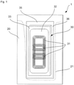
- Fig. 1
- is a schematic plan view of an embodiment of the invention referring to a configuration wherein a charging element is covered by a back layer;
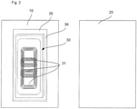
- Fig. 2
- is a schematic view of the embodiment shown in
Fig. 1 , wherein components of the charging device are shown in a disjoint state; - Fig. 3
- is a schematic side view of the embodiment of
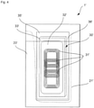
Fig. 1 ; - Fig. 4
- is a schematic plan view of a second embodiment of the invention referring to a configuration wherein a charging element is arranged between a back layer and a front layer;
- Fig. 5
- is a schematic side view of the embodiment of
Fig. 4 . - Embodiments of the invention are hereafter described in detail by way of non-limiting examples. Modifications of certain individual features can be combined with other features of the embodiment to provide additional examples of the invention.
- The charging
device 1 of the first embodiment comprises aback layer 10 made of fabric material, which includes in particular elastic synthetic fibers (for example elastane fibers). In the present embodiment, the fabric material contains 2-5% elastic synthetic fibers so as to provide theback layer 10 with high strength and elasticity. According to this configuration, theback layer 10 can be elastically deformed while being able to return to the original shape. - The charging
device 1 further comprises afront layer 20, which is according to the present embodiment made of a similar material as theback layer 10. Consequently, thefront layer 20 has similar properties as theback layer 10. - According to a modification of the embodiment, the
front layer 20 is made of a transparent synthetic material, for example a transparent foil. Thereby, the portion between the front and back layer is visible through thetransparent front layer 20. - The
front layer 20 is joined to theback layer 10 by sewing (topstitching 21) or welding in an edge portion of the corresponding elements so that thefront layer 20 and theback layer 10 form a pocket which is configured to receive a mobile phone (smartphone). Smartphones are generally designed in a rectangular shape. The dimensions of smartphones, however, vary depending on the size of the screen. - The
front layer 20 can be provided with an ultrasonic or heat-bonded transparent reinforcement tape so as to increase the tear resistance. A topstitching (seam) 21 is arranged along the reinforcement tape so as to connect thefront layer 20 to theback layer 10. Thetopstitching 21 also indicates the dimensions of the pocket so that the user recognizes where the smartphone is to be introduced. - A charging
element 30 is arranged at a back side of theback layer 10 in a portion covered by the pocket. As identified infigure 3 , asilver fabric 35 containing silver particles or silver fibers is provided at the side of the chargingelement 30 opposite to the back layer 10 (the side facing the wearer's body). Thesilver fabric 35 can be joined to theback layer 10 by gluing or sewing, wherein the chargingelement 30 can be fixed to thesilver fabric 35 by gluing or sewing as well. According to the embodiment, thesilver fabric 35 is attached to the back layer by sewing (seam 36). - The charging
element 30 is arranged within asilicone housing 33, thereby providing a flexible covering. Thesilicone housing 33 is a water-proof material so that the chargingelement 30, the piece of cloth or the like carrying the chargingelement 30 can be cleaned in a conventional washing machine or a dry-cleaning device. - The charging
element 30 comprises according to the present embodiment several coils 31. In particular, two coils are arranged next to each other, whereas a third coil is arranged in a state partially overlapping the previously mentioned coils. - The charging
element 30 further comprises acircuit board 32. Thecircuit board 32 can be made of an elastic or flexible material and comprises a control part for controlling the charging operation. In addition, a terminal for connecting the chargingelement 30 to a battery or accumulator device is connected to thecircuit board 32 of the chargingelement 30. The terminal can be a USB / micro USB-terminal. - For example, the circuit board can be formed of a polyimide film so that the
coils 31 can be attached to thecircuit board 32 by soldering. If thecircuit board 32 is made of a flexible material, the chargingelement 30 can be arranged in a piece of cloth, for example in the pocket of a jacket or a side portion of a pair of trousers, without negatively affecting the comfort of the wearer. - According to a modification of the embodiment, the circuit board of the charging element is made of a fiber-reinforced composite material, which is in contrast to a circuit board made of a polyimide film relatively stiff. Since the charging element is arranged within a silicone housing which provides a soft and resilient surface, the charging element does not affect the wearer's comfort. Alternatively, the charging element can be provided with a nano sealing.
-
Figs. 4-5 refer to a charging device 1' according to the second embodiment of the present invention, which differs from the first embodiment in that a charging element 30' is arranged between a back layer 10' and a front layer 20'. In other words, the charging element 30' is arranged within the pocket formed by connecting the front layer 20' to the back layer 10' by the topstitching 21'. - Similar to the first embodiment, the charging element 30' comprises one or several coils 31' which can be arranged as in the first embodiment. Further, the charging element 30' comprises a circuit board 32' which is either flexible or stiff. The coils 31' and the circuit board 32' are accommodated within a silicone housing 33' which is water-proof and provides comfort to the wearer.
- On a side of the charging element 30' facing the back layer 10', a silver fabric layer 35' is provided, which is attached to the back layer 10' by sewing (seam 36').
- On a portion of the back layer/front layer in the area of the opening of the pocket, an intermediate layer 40' is provided, which has, in plan view (
Fig. 4 ), a reduced size as compared to the back layer 10' and the front layer 20'. The intermediate layer 40' has substantially the same width as the front layer 20' and the back layer 10', but extends from the upper edge thereof only partially along the front/back layer. - The back layer 10', the intermediate layer 40' and the front layer 20' are connected by the topstitching 21' which also provides the borders of the pocket.
- Since the intermediate layer 40' extends such that a portion thereof partially covers the silver fabric layer 35' and a portion of the charging element 30', the charging element 30' can be held safely within the pocket when a mobile phone is repeatedly extracted from the pocket.
- As in the first embodiment, the front layer 20' may be formed of a similar material as the back layer 10'. According to a modification, the front layer 20' is made of a transparent material.
Claims (14)
- Charging device (1, 1') for inductive charging of an electronic device, for example a mobile phone, in particular a smartphone, a tablet computer or the like, comprising:a back layer (10, 10'),a front layer (20, 20') joined to the back layer (10, 10') so as to form a pocket for receiving the electronic device, anda charging element (30, 30') arranged to charge the electronic device arranged in the pocket, the charging element (30, 30') being configured for inductive charging of the electronic device,wherein the back layer (10, 10') and/or the front layer (20, 20') is elastically deformable,characterized in thata silver fabric layer (35) is arranged at a side of the charging element (30') opposite to the back layer (10), ora silver fabric layer (35') is arranged between the charging element (30') and the back layer (10').
- Charging device (1, 1') according to claim 1, characterized in that the back layer (10, 10') and/or the front layer (20, 20') is formed of a fabric material,which fabric material preferably comprises elastic synthetic fibers, in particular 1-10%, more preferably 2-5%, of elastic synthetic fibers,and/or wherein the fabric material has an elastic textile construction, or composition, such as texturized yarns or elastic fiber content.
- Charging device (1, 1') according to any of the previous claims, characterized in that the front layer (20, 20') is attached to the back layer (10, 10') by a topstitching pattern (21, 21').
- Charging device (1, 1') according to claim 3, characterized in that the front layer (20, 20') is provided with a seam tape, wherein the topstitching pattern (21, 21') is provided on the seam tape.
- Charging device (1, 1') according to any of the previous claims, wherein the silver fabric layer (35, 35') is attached to the back layer (10, 10') by sewing.
- Charging device (1, 1') according to claim 5, characterized in that the charging element (30) is attached to the silver fabric layer (35) by sewing.
- Charging device (1, 1') according to any of the previous claims, characterized in that the front layer (20, 20') is made of a transparent material or comprises a transparent front portion.
- Charging device (1, 1') according to any of the previous claims, characterized in that the charging element comprises a circuit board (32, 32'), which circuit board (32) is preferably made of an elastically deformable material, in particular polyimide,
or which a circuit board (32, 32') is made of a fiber-reinforced composite material. - Charging device (1, 1') according to any of the previous claims, characterized in that the front layer comprising a display, like a LED-display.
- Charging device (1, 1') according to any of the previous claims, characterized in that the charging element (30, 30') comprises at least one charging coil (31, 31'), preferably two or more charging coils (31, 31').
wherein it is preferred that the charging element (30, 30') comprises three charging coil (31, 31'), wherein a first and a second charging coil (31, 31') are arranged adjacent each other and the third charging coil (31, 31') is arranged so as to overlap the first and second charging coils (31, 31'). - Charging device (1, 1') according to any of the previous claims, characterized by a second pocket for accommodating a battery for the charging element (30, 30').
- Charging device (1') according to any of the previous claims, characterized in that the charging element (30') is arranged in the pocket formed by the back layer (10') and the front layer (20') or in a portion by the back layer (10) and the front layer (20).
- Charging device (1, 1') according to any of the previous claims, characterized in that the charging element (30, 30') is arranged in a silicone housing (33, 33').
- Wearable article, in particular a clothing article like a jacket, a shirt, a coat, a pair of trousers, or the like, or a bag, preferably a handbag, backpack, suitcase or briefcase, comprising a charging device according to any of the previous claims.
Applications Claiming Priority (1)
| Application Number | Priority Date | Filing Date | Title |
|---|---|---|---|
| PCT/EP2017/080818 WO2019105545A1 (en) | 2017-11-29 | 2017-11-29 | Charging device and wearable article |
Publications (2)
| Publication Number | Publication Date |
|---|---|
| EP3718189A1 EP3718189A1 (en) | 2020-10-07 |
| EP3718189B1 true EP3718189B1 (en) | 2022-03-23 |
Family
ID=60574571
Family Applications (1)
| Application Number | Title | Priority Date | Filing Date |
|---|---|---|---|
| EP17808853.0A Active EP3718189B1 (en) | 2017-11-29 | 2017-11-29 | Charging device and wearable article |
Country Status (3)
| Country | Link |
|---|---|
| EP (1) | EP3718189B1 (en) |
| ES (1) | ES2922275T3 (en) |
| WO (1) | WO2019105545A1 (en) |
Family Cites Families (6)
| Publication number | Priority date | Publication date | Assignee | Title |
|---|---|---|---|---|
| SG182745A1 (en) | 2010-01-27 | 2012-08-30 | Cynetic Designs Ltd | Modular pocket with inductive power and data |
| CN202513644U (en) * | 2012-03-23 | 2012-10-31 | 力新创展电子(香港)有限公司 | A portable system that can be charged wirelessly |
| KR101619594B1 (en) * | 2014-07-11 | 2016-05-10 | 현대자동차주식회사 | Wireless charge system in door pocket of vehicle |
| WO2016154778A1 (en) | 2015-03-27 | 2016-10-06 | Intel Corporation | Apparatus, system and method for transferring electrical energy in wearable device |
| US9906066B2 (en) * | 2015-04-13 | 2018-02-27 | Motorola Solutions, Inc. | Visor-mountable wireless charger and method of wireless charging |
| US10014710B2 (en) * | 2015-12-09 | 2018-07-03 | Intel Corporation | Foldable fabric-based packaging solution |
-
2017
- 2017-11-29 WO PCT/EP2017/080818 patent/WO2019105545A1/en not_active Ceased
- 2017-11-29 ES ES17808853T patent/ES2922275T3/en active Active
- 2017-11-29 EP EP17808853.0A patent/EP3718189B1/en active Active
Also Published As
| Publication number | Publication date |
|---|---|
| ES2922275T3 (en) | 2022-09-12 |
| WO2019105545A1 (en) | 2019-06-06 |
| EP3718189A1 (en) | 2020-10-07 |
Similar Documents
| Publication | Publication Date | Title |
|---|---|---|
| US12349243B2 (en) | Control device for mounting on electrically heated articles of apparel | |
| CN106484040B (en) | Enclosing characteristic portion for accessory device | |
| US20180289189A1 (en) | Clothes hanger recharger device | |
| US10795438B2 (en) | Electronic finger devices with charging and storage systems | |
| US20170110899A1 (en) | Galvanic Charging and Data Transfer of Remote Devices in a Personal Area Network System and Method | |
| US20090218884A1 (en) | Contactless Battery Charging Apparel | |
| CN105407662A (en) | Wearable electronic device | |
| WO2006125186A2 (en) | Discreet interface system | |
| KR101681906B1 (en) | Fabric-friendly rechargeable battery package | |
| US20080199770A1 (en) | Apparatus, System and Method For Battery Connections | |
| US20250088019A1 (en) | Rechargeable dc battery with magnetic connecting port | |
| WO2016190595A1 (en) | Functional clothing | |
| EP3718189B1 (en) | Charging device and wearable article | |
| JP2016213915A (en) | Wireless power supply system | |
| WO2018111178A1 (en) | A glove heater | |
| CN119677455A (en) | Integrated smart clothing | |
| EP1886544B1 (en) | Method and arrangement for protecting sensitive components by textile and product including said arrangement | |
| KR20210024920A (en) | Jacket with wireless self-charging module | |
| CN213547136U (en) | Charger baby | |
| KR101625535B1 (en) | Wireless charging apparatus for portable terminal | |
| US20220053637A1 (en) | Textile device configured to cooperate with an electronic device | |
| CN214479859U (en) | Power transmission charging trousers | |
| CA3212051A1 (en) | Rechargeable dc battery with magnetic connecting port | |
| CA3157132A1 (en) | Control device for mounting on electrically heated articles of apparel | |
| CA3157403A1 (en) | Article of warmth with integrated and concealed battery retention pocket |
Legal Events
| Date | Code | Title | Description |
|---|---|---|---|
| STAA | Information on the status of an ep patent application or granted ep patent |
Free format text: STATUS: UNKNOWN |
|
| STAA | Information on the status of an ep patent application or granted ep patent |
Free format text: STATUS: THE INTERNATIONAL PUBLICATION HAS BEEN MADE |
|
| PUAI | Public reference made under article 153(3) epc to a published international application that has entered the european phase |
Free format text: ORIGINAL CODE: 0009012 |
|
| STAA | Information on the status of an ep patent application or granted ep patent |
Free format text: STATUS: REQUEST FOR EXAMINATION WAS MADE |
|
| 17P | Request for examination filed |
Effective date: 20200616 |
|
| AK | Designated contracting states |
Kind code of ref document: A1 Designated state(s): AL AT BE BG CH CY CZ DE DK EE ES FI FR GB GR HR HU IE IS IT LI LT LU LV MC MK MT NL NO PL PT RO RS SE SI SK SM TR |
|
| AX | Request for extension of the european patent |
Extension state: BA ME |
|
| DAV | Request for validation of the european patent (deleted) | ||
| DAX | Request for extension of the european patent (deleted) | ||
| RIC1 | Information provided on ipc code assigned before grant |
Ipc: H02J 7/00 20060101AFI20210527BHEP Ipc: H02J 50/10 20160101ALI20210527BHEP Ipc: H04B 5/00 20060101ALI20210527BHEP Ipc: H02J 7/02 20160101ALI20210527BHEP Ipc: H01F 38/14 20060101ALI20210527BHEP Ipc: H02J 7/34 20060101ALI20210527BHEP |
|
| GRAP | Despatch of communication of intention to grant a patent |
Free format text: ORIGINAL CODE: EPIDOSNIGR1 |
|
| STAA | Information on the status of an ep patent application or granted ep patent |
Free format text: STATUS: GRANT OF PATENT IS INTENDED |
|
| INTG | Intention to grant announced |
Effective date: 20210702 |
|
| RAP3 | Party data changed (applicant data changed or rights of an application transferred) |
Owner name: KC TEXTIL GMBH |
|
| RIN1 | Information on inventor provided before grant (corrected) |
Inventor name: KUFNER, DOMINIK Inventor name: CINEL, SOFIA |
|
| GRAJ | Information related to disapproval of communication of intention to grant by the applicant or resumption of examination proceedings by the epo deleted |
Free format text: ORIGINAL CODE: EPIDOSDIGR1 |
|
| STAA | Information on the status of an ep patent application or granted ep patent |
Free format text: STATUS: REQUEST FOR EXAMINATION WAS MADE |
|
| GRAP | Despatch of communication of intention to grant a patent |
Free format text: ORIGINAL CODE: EPIDOSNIGR1 |
|
| STAA | Information on the status of an ep patent application or granted ep patent |
Free format text: STATUS: GRANT OF PATENT IS INTENDED |
|
| INTC | Intention to grant announced (deleted) | ||
| INTG | Intention to grant announced |
Effective date: 20211125 |
|
| GRAS | Grant fee paid |
Free format text: ORIGINAL CODE: EPIDOSNIGR3 |
|
| GRAA | (expected) grant |
Free format text: ORIGINAL CODE: 0009210 |
|
| STAA | Information on the status of an ep patent application or granted ep patent |
Free format text: STATUS: THE PATENT HAS BEEN GRANTED |
|
| AK | Designated contracting states |
Kind code of ref document: B1 Designated state(s): AL AT BE BG CH CY CZ DE DK EE ES FI FR GB GR HR HU IE IS IT LI LT LU LV MC MK MT NL NO PL PT RO RS SE SI SK SM TR |
|
| REG | Reference to a national code |
Ref country code: GB Ref legal event code: FG4D |
|
| REG | Reference to a national code |
Ref country code: CH Ref legal event code: EP |
|
| REG | Reference to a national code |
Ref country code: IE Ref legal event code: FG4D |
|
| REG | Reference to a national code |
Ref country code: AT Ref legal event code: REF Ref document number: 1478111 Country of ref document: AT Kind code of ref document: T Effective date: 20220415 |
|
| REG | Reference to a national code |
Ref country code: DE Ref legal event code: R096 Ref document number: 602017054993 Country of ref document: DE |
|
| REG | Reference to a national code |
Ref country code: LT Ref legal event code: MG9D |
|
| REG | Reference to a national code |
Ref country code: NL Ref legal event code: MP Effective date: 20220323 |
|
| PG25 | Lapsed in a contracting state [announced via postgrant information from national office to epo] |
Ref country code: SE Free format text: LAPSE BECAUSE OF FAILURE TO SUBMIT A TRANSLATION OF THE DESCRIPTION OR TO PAY THE FEE WITHIN THE PRESCRIBED TIME-LIMIT Effective date: 20220323 Ref country code: RS Free format text: LAPSE BECAUSE OF FAILURE TO SUBMIT A TRANSLATION OF THE DESCRIPTION OR TO PAY THE FEE WITHIN THE PRESCRIBED TIME-LIMIT Effective date: 20220323 Ref country code: NO Free format text: LAPSE BECAUSE OF FAILURE TO SUBMIT A TRANSLATION OF THE DESCRIPTION OR TO PAY THE FEE WITHIN THE PRESCRIBED TIME-LIMIT Effective date: 20220623 Ref country code: LT Free format text: LAPSE BECAUSE OF FAILURE TO SUBMIT A TRANSLATION OF THE DESCRIPTION OR TO PAY THE FEE WITHIN THE PRESCRIBED TIME-LIMIT Effective date: 20220323 Ref country code: HR Free format text: LAPSE BECAUSE OF FAILURE TO SUBMIT A TRANSLATION OF THE DESCRIPTION OR TO PAY THE FEE WITHIN THE PRESCRIBED TIME-LIMIT Effective date: 20220323 Ref country code: BG Free format text: LAPSE BECAUSE OF FAILURE TO SUBMIT A TRANSLATION OF THE DESCRIPTION OR TO PAY THE FEE WITHIN THE PRESCRIBED TIME-LIMIT Effective date: 20220623 |
|
| REG | Reference to a national code |
Ref country code: AT Ref legal event code: MK05 Ref document number: 1478111 Country of ref document: AT Kind code of ref document: T Effective date: 20220323 |
|
| PG25 | Lapsed in a contracting state [announced via postgrant information from national office to epo] |
Ref country code: LV Free format text: LAPSE BECAUSE OF FAILURE TO SUBMIT A TRANSLATION OF THE DESCRIPTION OR TO PAY THE FEE WITHIN THE PRESCRIBED TIME-LIMIT Effective date: 20220323 Ref country code: GR Free format text: LAPSE BECAUSE OF FAILURE TO SUBMIT A TRANSLATION OF THE DESCRIPTION OR TO PAY THE FEE WITHIN THE PRESCRIBED TIME-LIMIT Effective date: 20220624 Ref country code: FI Free format text: LAPSE BECAUSE OF FAILURE TO SUBMIT A TRANSLATION OF THE DESCRIPTION OR TO PAY THE FEE WITHIN THE PRESCRIBED TIME-LIMIT Effective date: 20220323 |
|
| REG | Reference to a national code |
Ref country code: ES Ref legal event code: FG2A Ref document number: 2922275 Country of ref document: ES Kind code of ref document: T3 Effective date: 20220912 |
|
| PG25 | Lapsed in a contracting state [announced via postgrant information from national office to epo] |
Ref country code: NL Free format text: LAPSE BECAUSE OF FAILURE TO SUBMIT A TRANSLATION OF THE DESCRIPTION OR TO PAY THE FEE WITHIN THE PRESCRIBED TIME-LIMIT Effective date: 20220323 |
|
| PG25 | Lapsed in a contracting state [announced via postgrant information from national office to epo] |
Ref country code: SM Free format text: LAPSE BECAUSE OF FAILURE TO SUBMIT A TRANSLATION OF THE DESCRIPTION OR TO PAY THE FEE WITHIN THE PRESCRIBED TIME-LIMIT Effective date: 20220323 Ref country code: SK Free format text: LAPSE BECAUSE OF FAILURE TO SUBMIT A TRANSLATION OF THE DESCRIPTION OR TO PAY THE FEE WITHIN THE PRESCRIBED TIME-LIMIT Effective date: 20220323 Ref country code: RO Free format text: LAPSE BECAUSE OF FAILURE TO SUBMIT A TRANSLATION OF THE DESCRIPTION OR TO PAY THE FEE WITHIN THE PRESCRIBED TIME-LIMIT Effective date: 20220323 Ref country code: PT Free format text: LAPSE BECAUSE OF FAILURE TO SUBMIT A TRANSLATION OF THE DESCRIPTION OR TO PAY THE FEE WITHIN THE PRESCRIBED TIME-LIMIT Effective date: 20220725 Ref country code: EE Free format text: LAPSE BECAUSE OF FAILURE TO SUBMIT A TRANSLATION OF THE DESCRIPTION OR TO PAY THE FEE WITHIN THE PRESCRIBED TIME-LIMIT Effective date: 20220323 Ref country code: CZ Free format text: LAPSE BECAUSE OF FAILURE TO SUBMIT A TRANSLATION OF THE DESCRIPTION OR TO PAY THE FEE WITHIN THE PRESCRIBED TIME-LIMIT Effective date: 20220323 Ref country code: AT Free format text: LAPSE BECAUSE OF FAILURE TO SUBMIT A TRANSLATION OF THE DESCRIPTION OR TO PAY THE FEE WITHIN THE PRESCRIBED TIME-LIMIT Effective date: 20220323 |
|
| PG25 | Lapsed in a contracting state [announced via postgrant information from national office to epo] |
Ref country code: PL Free format text: LAPSE BECAUSE OF FAILURE TO SUBMIT A TRANSLATION OF THE DESCRIPTION OR TO PAY THE FEE WITHIN THE PRESCRIBED TIME-LIMIT Effective date: 20220323 Ref country code: IS Free format text: LAPSE BECAUSE OF FAILURE TO SUBMIT A TRANSLATION OF THE DESCRIPTION OR TO PAY THE FEE WITHIN THE PRESCRIBED TIME-LIMIT Effective date: 20220723 Ref country code: AL Free format text: LAPSE BECAUSE OF FAILURE TO SUBMIT A TRANSLATION OF THE DESCRIPTION OR TO PAY THE FEE WITHIN THE PRESCRIBED TIME-LIMIT Effective date: 20220323 |
|
| REG | Reference to a national code |
Ref country code: DE Ref legal event code: R097 Ref document number: 602017054993 Country of ref document: DE |
|
| PLBE | No opposition filed within time limit |
Free format text: ORIGINAL CODE: 0009261 |
|
| STAA | Information on the status of an ep patent application or granted ep patent |
Free format text: STATUS: NO OPPOSITION FILED WITHIN TIME LIMIT |
|
| PG25 | Lapsed in a contracting state [announced via postgrant information from national office to epo] |
Ref country code: DK Free format text: LAPSE BECAUSE OF FAILURE TO SUBMIT A TRANSLATION OF THE DESCRIPTION OR TO PAY THE FEE WITHIN THE PRESCRIBED TIME-LIMIT Effective date: 20220323 |
|
| PGFP | Annual fee paid to national office [announced via postgrant information from national office to epo] |
Ref country code: ES Payment date: 20221202 Year of fee payment: 6 |
|
| 26N | No opposition filed |
Effective date: 20230102 |
|
| PG25 | Lapsed in a contracting state [announced via postgrant information from national office to epo] |
Ref country code: SI Free format text: LAPSE BECAUSE OF FAILURE TO SUBMIT A TRANSLATION OF THE DESCRIPTION OR TO PAY THE FEE WITHIN THE PRESCRIBED TIME-LIMIT Effective date: 20220323 |
|
| PG25 | Lapsed in a contracting state [announced via postgrant information from national office to epo] |
Ref country code: MC Free format text: LAPSE BECAUSE OF FAILURE TO SUBMIT A TRANSLATION OF THE DESCRIPTION OR TO PAY THE FEE WITHIN THE PRESCRIBED TIME-LIMIT Effective date: 20220323 |
|
| REG | Reference to a national code |
Ref country code: CH Ref legal event code: PL |
|
| GBPC | Gb: european patent ceased through non-payment of renewal fee |
Effective date: 20221129 |
|
| REG | Reference to a national code |
Ref country code: BE Ref legal event code: MM Effective date: 20221130 |
|
| PG25 | Lapsed in a contracting state [announced via postgrant information from national office to epo] |
Ref country code: LI Free format text: LAPSE BECAUSE OF NON-PAYMENT OF DUE FEES Effective date: 20221130 Ref country code: CH Free format text: LAPSE BECAUSE OF NON-PAYMENT OF DUE FEES Effective date: 20221130 |
|
| PG25 | Lapsed in a contracting state [announced via postgrant information from national office to epo] |
Ref country code: LU Free format text: LAPSE BECAUSE OF NON-PAYMENT OF DUE FEES Effective date: 20221129 |
|
| PG25 | Lapsed in a contracting state [announced via postgrant information from national office to epo] |
Ref country code: IE Free format text: LAPSE BECAUSE OF NON-PAYMENT OF DUE FEES Effective date: 20221129 Ref country code: GB Free format text: LAPSE BECAUSE OF NON-PAYMENT OF DUE FEES Effective date: 20221129 |
|
| PG25 | Lapsed in a contracting state [announced via postgrant information from national office to epo] |
Ref country code: FR Free format text: LAPSE BECAUSE OF NON-PAYMENT OF DUE FEES Effective date: 20221130 Ref country code: BE Free format text: LAPSE BECAUSE OF NON-PAYMENT OF DUE FEES Effective date: 20221130 |
|
| PG25 | Lapsed in a contracting state [announced via postgrant information from national office to epo] |
Ref country code: CY Free format text: LAPSE BECAUSE OF FAILURE TO SUBMIT A TRANSLATION OF THE DESCRIPTION OR TO PAY THE FEE WITHIN THE PRESCRIBED TIME-LIMIT Effective date: 20220323 |
|
| PG25 | Lapsed in a contracting state [announced via postgrant information from national office to epo] |
Ref country code: MK Free format text: LAPSE BECAUSE OF FAILURE TO SUBMIT A TRANSLATION OF THE DESCRIPTION OR TO PAY THE FEE WITHIN THE PRESCRIBED TIME-LIMIT Effective date: 20220323 Ref country code: HU Free format text: LAPSE BECAUSE OF FAILURE TO SUBMIT A TRANSLATION OF THE DESCRIPTION OR TO PAY THE FEE WITHIN THE PRESCRIBED TIME-LIMIT; INVALID AB INITIO Effective date: 20171129 |
|
| PG25 | Lapsed in a contracting state [announced via postgrant information from national office to epo] |
Ref country code: TR Free format text: LAPSE BECAUSE OF FAILURE TO SUBMIT A TRANSLATION OF THE DESCRIPTION OR TO PAY THE FEE WITHIN THE PRESCRIBED TIME-LIMIT Effective date: 20220323 |
|
| PGFP | Annual fee paid to national office [announced via postgrant information from national office to epo] |
Ref country code: DE Payment date: 20240517 Year of fee payment: 7 |
|
| PG25 | Lapsed in a contracting state [announced via postgrant information from national office to epo] |
Ref country code: MT Free format text: LAPSE BECAUSE OF FAILURE TO SUBMIT A TRANSLATION OF THE DESCRIPTION OR TO PAY THE FEE WITHIN THE PRESCRIBED TIME-LIMIT Effective date: 20220323 |
|
| REG | Reference to a national code |
Ref country code: ES Ref legal event code: FD2A Effective date: 20250103 |
|
| PG25 | Lapsed in a contracting state [announced via postgrant information from national office to epo] |
Ref country code: ES Free format text: LAPSE BECAUSE OF NON-PAYMENT OF DUE FEES Effective date: 20231130 |
|
| PG25 | Lapsed in a contracting state [announced via postgrant information from national office to epo] |
Ref country code: ES Free format text: LAPSE BECAUSE OF NON-PAYMENT OF DUE FEES Effective date: 20231130 |
|
| REG | Reference to a national code |
Ref country code: DE Ref legal event code: R119 Ref document number: 602017054993 Country of ref document: DE |
|
| PG25 | Lapsed in a contracting state [announced via postgrant information from national office to epo] |
Ref country code: DE Free format text: LAPSE BECAUSE OF NON-PAYMENT OF DUE FEES Effective date: 20250603 |
|
| PGFP | Annual fee paid to national office [announced via postgrant information from national office to epo] |
Ref country code: IT Payment date: 20251124 Year of fee payment: 9 |