EP3717688B1 - Tumble dryer - Google Patents
Tumble dryer Download PDFInfo
- Publication number
- EP3717688B1 EP3717688B1 EP17805188.4A EP17805188A EP3717688B1 EP 3717688 B1 EP3717688 B1 EP 3717688B1 EP 17805188 A EP17805188 A EP 17805188A EP 3717688 B1 EP3717688 B1 EP 3717688B1
- Authority
- EP
- European Patent Office
- Prior art keywords
- flow
- tumble dryer
- drum
- compressor
- heat pump
- Prior art date
- Legal status (The legal status is an assumption and is not a legal conclusion. Google has not performed a legal analysis and makes no representation as to the accuracy of the status listed.)
- Active
Links
Images

Classifications
-
- D—TEXTILES; PAPER
- D06—TREATMENT OF TEXTILES OR THE LIKE; LAUNDERING; FLEXIBLE MATERIALS NOT OTHERWISE PROVIDED FOR
- D06F—LAUNDERING, DRYING, IRONING, PRESSING OR FOLDING TEXTILE ARTICLES
- D06F58/00—Domestic laundry dryers
- D06F58/02—Domestic laundry dryers having dryer drums rotating about a horizontal axis
-
- D—TEXTILES; PAPER
- D06—TREATMENT OF TEXTILES OR THE LIKE; LAUNDERING; FLEXIBLE MATERIALS NOT OTHERWISE PROVIDED FOR
- D06F—LAUNDERING, DRYING, IRONING, PRESSING OR FOLDING TEXTILE ARTICLES
- D06F34/00—Details of control systems for washing machines, washer-dryers or laundry dryers
- D06F34/08—Control circuits or arrangements thereof
-
- D—TEXTILES; PAPER
- D06—TREATMENT OF TEXTILES OR THE LIKE; LAUNDERING; FLEXIBLE MATERIALS NOT OTHERWISE PROVIDED FOR
- D06F—LAUNDERING, DRYING, IRONING, PRESSING OR FOLDING TEXTILE ARTICLES
- D06F58/00—Domestic laundry dryers
- D06F58/20—General details of domestic laundry dryers
- D06F58/206—Heat pump arrangements
-
- D—TEXTILES; PAPER
- D06—TREATMENT OF TEXTILES OR THE LIKE; LAUNDERING; FLEXIBLE MATERIALS NOT OTHERWISE PROVIDED FOR
- D06F—LAUNDERING, DRYING, IRONING, PRESSING OR FOLDING TEXTILE ARTICLES
- D06F58/00—Domestic laundry dryers
- D06F58/20—General details of domestic laundry dryers
- D06F58/22—Lint collecting arrangements
-
- D—TEXTILES; PAPER
- D06—TREATMENT OF TEXTILES OR THE LIKE; LAUNDERING; FLEXIBLE MATERIALS NOT OTHERWISE PROVIDED FOR
- D06F—LAUNDERING, DRYING, IRONING, PRESSING OR FOLDING TEXTILE ARTICLES
- D06F58/00—Domestic laundry dryers
- D06F58/20—General details of domestic laundry dryers
- D06F58/24—Condensing arrangements
-
- D—TEXTILES; PAPER
- D06—TREATMENT OF TEXTILES OR THE LIKE; LAUNDERING; FLEXIBLE MATERIALS NOT OTHERWISE PROVIDED FOR
- D06F—LAUNDERING, DRYING, IRONING, PRESSING OR FOLDING TEXTILE ARTICLES
- D06F2103/00—Parameters monitored or detected for the control of domestic laundry washing machines, washer-dryers or laundry dryers
- D06F2103/40—Opening or locking status of doors
-
- D—TEXTILES; PAPER
- D06—TREATMENT OF TEXTILES OR THE LIKE; LAUNDERING; FLEXIBLE MATERIALS NOT OTHERWISE PROVIDED FOR
- D06F—LAUNDERING, DRYING, IRONING, PRESSING OR FOLDING TEXTILE ARTICLES
- D06F2103/00—Parameters monitored or detected for the control of domestic laundry washing machines, washer-dryers or laundry dryers
- D06F2103/50—Parameters monitored or detected for the control of domestic laundry washing machines, washer-dryers or laundry dryers related to heat pumps, e.g. pressure or flow rate
-
- D—TEXTILES; PAPER
- D06—TREATMENT OF TEXTILES OR THE LIKE; LAUNDERING; FLEXIBLE MATERIALS NOT OTHERWISE PROVIDED FOR
- D06F—LAUNDERING, DRYING, IRONING, PRESSING OR FOLDING TEXTILE ARTICLES
- D06F2105/00—Systems or parameters controlled or affected by the control systems of washing machines, washer-dryers or laundry dryers
- D06F2105/26—Heat pumps
-
- D—TEXTILES; PAPER
- D06—TREATMENT OF TEXTILES OR THE LIKE; LAUNDERING; FLEXIBLE MATERIALS NOT OTHERWISE PROVIDED FOR
- D06F—LAUNDERING, DRYING, IRONING, PRESSING OR FOLDING TEXTILE ARTICLES
- D06F58/00—Domestic laundry dryers
- D06F58/02—Domestic laundry dryers having dryer drums rotating about a horizontal axis
- D06F58/04—Details
-
- D—TEXTILES; PAPER
- D06—TREATMENT OF TEXTILES OR THE LIKE; LAUNDERING; FLEXIBLE MATERIALS NOT OTHERWISE PROVIDED FOR
- D06F—LAUNDERING, DRYING, IRONING, PRESSING OR FOLDING TEXTILE ARTICLES
- D06F58/00—Domestic laundry dryers
- D06F58/20—General details of domestic laundry dryers
-
- D—TEXTILES; PAPER
- D06—TREATMENT OF TEXTILES OR THE LIKE; LAUNDERING; FLEXIBLE MATERIALS NOT OTHERWISE PROVIDED FOR
- D06F—LAUNDERING, DRYING, IRONING, PRESSING OR FOLDING TEXTILE ARTICLES
- D06F58/00—Domestic laundry dryers
- D06F58/32—Control of operations performed in domestic laundry dryers
- D06F58/34—Control of operations performed in domestic laundry dryers characterised by the purpose or target of the control
- D06F58/50—Responding to irregular working conditions, e.g. malfunctioning of blowers
Definitions
- the present disclosure relates to a tumble dryer comprising a housing, a drum in the housing being accessible from a front side of the housing and being rotatable about its center axis, a fan arrangement for producing a flow of process air passing through the drum, and a heat pump for drying the process air before entering the drum, the heat pump comprising a compressor, a condenser, an expansion valve, and an evaporator forming a refrigerant fluid loop.
- Such a tumble dryer is shown for instance in EP-3118365-A1 , one problem with such tumble dryers is how to improve their energy efficiency further.
- tumble dryers are: US 2012/186305 A1 , which relates to a laundry dryer comprising a blower situated to blow dry air such that the dry air sequentially circulates from the drum, heat absorber, radiator, to the drum again.
- WO 2016/204415 A1 relates to a clothes dryer including a drum, a heat pump cycle having a first evaporator, a compressor and a condenser, wherein the heat pump cycle includes second to n th evaporators disposed in series with the first evaporator within an air duct.
- EP 2489775 A1 relates to a heat pump laundry dryer including a closed refrigerant circuit and a drying air circuit.
- the refrigerant circuit includes a compressor, a condenser, an expansion device and a main evaporator.
- the drying air circuit includes the main evaporator, the condenser, a laundry drum and at least one fan.
- EP 3246458 A1 relates to a laundry treating apparatus including a cabinet for receiving laundry, a machinery compartment with an air supply unit for dehumidifying or heating air in the receiving space and supplying the dehumidified air into the receiving space.
- JP 2006230887 A relates to a washing machine with an evaporator and a condenser housed upstream and downstream in a heat exchange duct.
- dehumidification is performed based on cooling of air in a water tank by the evaporator, and air is warmed based on heating of dehumidified air by the condenser.
- EP 2733254 A1 relates to a heat pump laundry dryer comprising a laundry drum, a process air fan, a heat pump system with a variable speed compressor, and a cooling fan unit arranged for cooling the compressor and for cooling an inverter board of the compressor.
- the rotatable drum comprises a circular rear wall with air inlet openings and a radial cylindrical wall with air outlet openings, and the compressor is adapted to be run by an inverter, allowing the compressor output to be varied.
- the expansion valve is also controllable. With such a configuration, a high process air flow can be maintained through the drum, even if a front door of the dryer is opened. At the same time, the compressor and the expansion valve can be controlled to provide a heat pump effect that varies depending on the circumstances to provide improved efficiency.
- the evaporator may comprise a flow divider, dividing a refrigerant fluid flow into a plurality of sub-flows for different portions of the evaporator.
- the controllable expansion valve may be attached to the flow divider. A close connection between the expansion valve and the flow divider provides a more laminar flow achieving an equal division of the refrigerant into the different sub-flows. This in turn provides a more efficient evaporator.
- the conduit between the expansion valve and the flow divider may be straight, and may preferably have a length less than 100 mm.
- the expansion valve and the compressor may be controlled by means of a controller based on sensor data from a first and a second pressure sensor and a first and a second temperature sensor.
- the first pressure sensor and the first temperature sensor may be located in the refrigerant fluid flow from the expansion valve to the compressor, while the second pressure sensor and the second temperature sensor may be located in the refrigerant fluid flow from the compressor to the expansion valve.
- the controller has knowledge of both the high and low temperatures and pressures of the heat pump circuit, and can therefore control the heat pump to a desired heat pump cycle envelope. This enables a heat pump operation with improved efficiency.
- a threaded connection adapted to receive a replacement sensor in each of the heat pump circuit path from the expansion valve to the compressor, and/or from the compressor to the expansion valve. This allows a malfunctioning pressure or temperature sensor to be replaced without physically removing the faulty sensor and possibly without removing most of the refrigerant in the heat pump circuit. Instead, a replacement sensor is simply fitted at the threaded connection to record temperature or pressure data.
- the inverter comprises a heatsink cooled by heat pump flow which provides efficient cooling of the inverter electronics and reuses some of the dissipated energy in the heat pump drying process.
- the heat pump flow may be a refrigerant flow, where the heat sink is cooled by a suction line between the evaporator and the compressor. Then, a loop of the suction line may be embedded in the heat sink.
- the heat pump circuit may be enclosed in an insulating shell, and the suction line may reach out of the insulating shell to reach the heat sink.
- the heat pump flow is a process air flow, the heat sink being cooled by the process air flow leaving the evaporator.
- the heat pump circuit may be enclosed in an insulating shell and the heat sink may reach to the inside of the shell.
- the inverter electronics may be located in the comparatively dryer environment outside the shell.
- the drum in the tumble dryer is accessible through a door, and control of the compressor may be adapted to keep the refrigerant flow on, i.e. the compressor switched on when the door is opened, while only reducing the refrigerant flow. This implies fewer start/stop cycles of the compressor if the door e.g. is opened frequently to add or remove laundry.
- the refrigerant flow may however be reduced to 30-60% of the flow before the door was opened.
- the compressor may subsequently be switched off.
- the heat pump may be enclosed in an insulating shell and there may be provided an opening in the shell between the condenser and the inlet of the drum. This serves to avoid overpressure in the drum that could cause hot and humid air to be pressed into spaces containing electronics and the like, which should be avoided. There may be provided a corresponding opening in the outer housing.
- the space outside the drum's cylindrical periphery may be configured as a duct leading to a filter. This may provide a considerable flow area with a comparatively small restriction of the air flow, which may allow for a high capacity.
- a filter for removing lint from the air flow may be located below the drum. This allows the use of a large filter, substantially as wide as the cylindrical diameter of the drum, and as deep as the depth of the drum. This provides a relatively small flow restriction.
- the present disclosure relates generally to a tumble dryer which is provided with a heat pump in order to achieve energy-efficient drying of laundry.
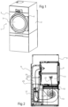
- An example of a tumble dryer 1 is illustrated in fig 1 .
- the tumble dryer 1 has a housing 2 with a front side 3 which is provided with a door 5 or hatch, attached to the front side 3 with hinges 7, which provides access to a tumble dryer drum where wet laundry can be loaded.
- Fig 2 illustrates a cross section through a tumble dryer with a heat pump arrangement.
- process air drying the laundry can circulate mostly within the outer enclosure of the tumble dryer, although some exchange of air with the outside may be allowed as will be shown.
- Fig 2 illustrates in a cross section, components of such a tumble dryer as well as a process air flow path 21.
- the tumble dryer comprises a drum 11 in which wet laundry is placed. While the drum 11 rotates, a flow 21 of relatively dry process air is fed therethrough. The flow is provided by a fan 13 or blower, which in the illustrated case is located in a space below the drum 11.
- the tumble dryer includes a heat pump arrangement with an evaporator 15, a compressor 17, a condenser 19, and an expansion valve 16 (cf. fig 3 ).
- a refrigerant medium is forced through the heat pump arrangement by the compressor 17, and gathers energy in the evaporator 15 which is released in the condenser 19, as is well known per se.
- an air flow 21 is achieved where hot, humid air is extracted from the perforated drum 11 by means of the fan 13.
- the air flow passes a filter 12 before reaching the fan 13 and arrives at the evaporator 15, which cools the air flow such that moisture therein condenses into liquid water.
- This water is collected in the bottom section of the tumble dryer and may be drained therefrom through a tube (not shown).
- a compressor 17 is provided to obtain the heat pump refrigerant flow.
- the heat pump may be enclosed in an insulating shell 23, for instance made of expanded propylene, EPP. This improves the energy efficiency of the tumble dryer, as less heat may leak to the ambient space.
- the present tumble dryer involves a number of improvements, for instance providing increased energy-efficiency and/or capacity.
- a high-capacity tumble dryer mainly intended for professional use or for use in shared laundry facilities is shown.
- Such tumble dryers may comprise a drum 11 with air inlet openings in its circular rear wall and air outlet openings in its radial cylindrical wall, particularly in the front part thereof, to provide a process air flow through the drum.
- This may be combined with a lint removing filter 12 located below the drum, rather than with a filter provided outlet located in connection with the front wall door 5.
- the improvements described herein may also be used in connection with typical domestic tumble dryers intended for use a couple of times per week.
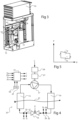
- Fig 3 shows a perspective view of the heat pump arrangement of the tumble dryer in fig 2
- fig 4 illustrates schematically the heat pump circuit 25 of the heat pump in fig 3
- the compressor 17 is adapted to be run by an inverter-controlled motor 27.
- An inverter 29 is provided allowing the compressor 17 output to be varied. This is in contrast to systems where compressors are merely switched on and off to control their operation.
- the expansion valve 16 is controllable, typically being an electronic expansion valve, EEV.
- the compressor 17 and the expansion valve 16 are controlled by a controller 31, based on a number of inputs.
- a control signal C for the compressor 17, and a control signal V for the expansion valve 16 are thus provided.
- the heat pump circuit 25 may comprise a first 33 and a second 35 pressure sensor and a first 37 and a second 39 temperature sensor.
- the first pressure sensor 33 and the first temperature sensor 37 are located in the refrigerant fluid flow from the expansion valve 16 to the compressor 17, i.e. in the cold side of the circuit.
- the second pressure sensor 35 and the second temperature sensor 37 are located in the refrigerant fluid flow from the compressor 17 to the expansion valve 16, i.e. in the hot side of the circuit 25.
- FIG 5 schematically illustrates an operation cycle where the refrigerant fluid is affected by the compressor, a, condenser, b, the expansion valve, c, and the evaporator, d, while energy W is taken away from and moved back to the process air flow 21, cf. fig 5 .
- the expansion valve is controlled to match the compressor output.
- the compressor 17 output may be reduced, although it may be advantageous to run the compressor 17 rather than switching it off completely.
- the compressor output may be reduced to 30-60% of the output before the door was opened, in terms of compressor rpm.
- the compressor 17 may go from 110 to 50 Hz when the door is opened. This may for instance improve the durability of the compressor as the number of start/stop cycles during normal use can be reduced.
- thermoelectric circuit 25 It is also possible to control the heat pump circuit 25 based on e.g. a sensed humidity from a humidity sensor 61 in the process air stream 21 when leaving the drum 11. This allows for instance leaving a residual humidity in the laundry that may be preferred in some types of fabric. It is also possible to achieve a process cycle with a predefined maximum process air temperature, which may be preferred for other fabrics.
- Fig 6 shows enlarged a portion A of fig 3 where a part of the heat pump circuit is shown, namely leading from the condenser 19 to the expansion valve 16 and via a filter 41.
- a connection 43 that branches away from the heat pump circuit 25.
- This connection 43 has a threaded end, which in the illustrated state is plugged.
- the threaded connection can be used to fit a replacement sensor, which allows for simplified maintenance.
- the temperature and pressure sensors that the heat pump circuit is originally provided with may be built into the circuit and the malfunctioning sensor may remain at its location while its leads are instead connected to the replacement sensor.
- Such a threaded connection can be useful also in tumble dryers with other drum configurations, such as tumble dryers with a drum outlet arranged at the tumble dryer door.
- Switching circuits of the inverter 29 that controls the compressor motor 27 produce heat that need be dissipated to ensure proper function.
- This also applies to other electronics of the tumble dryer, such as for instance electronics of the control unit 31. Normally, this would be done simply by connecting the electronics to a heat sink, dissipating the heat to the ambient space.
- the present disclosure suggests using a heat pump flow to improve this cooling. This provides very efficient cooling of inverter and optionally other electronics and may additionally improve the energy efficiency of the tumble dryer as a whole.
- the heat pump flow may be the flow of the heat pump's refrigerant, or the flow of air dried by the heat pump.
- Fig 7-10 show a first example of a heat pump flow cooled inverter.
- a suction line 45 for leading refrigerant in the heat pump circuit from the evaporator 15 to the compressor 17 is used to cool the electronics, as shown in fig 7 illustrating the heat pump arrangement as seen from the rear of the tumble dryer.
- This suction line 45 is led out of the insulating shell 23 to provide an external loop.
- the electronics may be attached to a heat sink block 47 through which the suction line 45 passes. Electronics to be cooled may be located on both sides of the heat sink block 47 as best seen in the side view of fig 8 .
- Fig 9 shows the same view as in fig 7 with the suction line 45 exposed, and fig 10 illustrates enlarged the portion C of fig 9 .
- the heat sink block 47 may comprise two halves that are fitted to enclose the suction line loop 45.
- a groove suitable to enclose a part of the suction line may be machined into the heat sink block 47 halves, which may be a solid metal blocks, for instance made of aluminum. It is possible to provide a heat transferring paste in the grooves to increase heat conduction from the heat sink although this is not necessary. In this way, very effective transfer of heat from the heat sink block 47 to the suction line 45 takes place, and the electronics becomes very efficiently cooled. Additionally, the cool refrigerant flow in the suction line becomes heated before reaching the compressor, which improves the heat pump efficiency further.
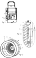
- Fig 11 shows an alternative for cooling an inverter with a heat pump flow.
- the rear wall of the insulating shell has been taken away to expose the interior of the heat pump arrangement.
- the inverter 29 electronics is attached to a heat sink block 49 which reaches through a wall of the insulating shell 23. This allows the other end of the heat sink 49 to reach into the process air stream 21 inside the shell.
- the heat sink projects into the air stream between the evaporator and the compressor, i.e. in the cooler portion of the stream path. This as well provides efficient cooling of the inverter electronics and recycling of heat that would otherwise be lost in the tumble dryer.
- the inverter 29 electronics may be placed outside the shell 23 where humidity is lower.
- cooling arrangements illustrated in figs 7-11 may be useful also in tumble dryers with other drum configurations, such as tumble dryers with a drum outlet arranged at the tumble dryer door.
- an opening 51 in the outer shell 23 is shown above the condenser 19 and connects the process air path 21 to the ambient space outside the shell 23 at this location. This means that any overpressure in the air flow reaching the drum 11 can be reduced, which is useful, since such overpressure could otherwise force humid air into devices, e.g. ball bearings or electronics, that should preferably be kept dry.
- a corresponding opening 60 may be provided in the outer housing 2 to let the hot air out of the tumble dryer.
- Fig 12 shows a tumble dryer drum 11.
- the drum has a circular rear wall 53 with air inlet openings and a radial cylindrical wall 55 with air outlet openings in the indicated area 62.
- This area may comprise a large number of openings/holes, together providing a significant outlet. It may be advantageous to locate the openings of the cylindrical part in the front part of the drum such that the air flow passes most of the drum's 11 space.
- no outlet connected to the tumble dryer door 5 cf. fig 1
- the processes can be kept running, although suitably at a lower level. This reduces the number of starts/stops of the compressor and may improve its durability.
- the heat pump is switched off.
- a filter 12 (cf. fig 2 ) may be placed under the drum, and may take up a large part of the area between the drum and the filter arrangement. This allows the use of a large, high-capacity filter, and high process air flows. Further, as air is let out of the drum 11 through a considerable flow area comprised by the openings in the outlet area 62, flow restriction can be reduced, as compared to where openings are arranged at the door. Additionally, the space outside the drum's cylindrical periphery almost as a whole can be used as a duct leading down to the lint filter under the drum 11. In this way, the flow through the drum can be increased which is particularly useful in a high-capacity heat pump tumble dryer.
- Fig 13 shows an enlarged portion B of fig 3 .
- a flow divider 57 that splits the refrigerant flow from the expansion valve 16 into a number of sub-flows 58 that are passed to different portions of the evaporator.
- the controllable expansion valve 16 controlled electronically by means of a solenoid 54, is connected to the flow divider 57 by means of a straight conduit 56.
- the conduit 56 is short, e.g. shorter than 100 mm to improve this effect further.
Landscapes
- Engineering & Computer Science (AREA)
- Textile Engineering (AREA)
- Detail Structures Of Washing Machines And Dryers (AREA)
- Control Of Washing Machine And Dryer (AREA)
Description
- The present disclosure relates to a tumble dryer comprising a housing, a drum in the housing being accessible from a front side of the housing and being rotatable about its center axis, a fan arrangement for producing a flow of process air passing through the drum, and a heat pump for drying the process air before entering the drum, the heat pump comprising a compressor, a condenser, an expansion valve, and an evaporator forming a refrigerant fluid loop.
- Such a tumble dryer is shown for instance in
EP-3118365-A1 , one problem with such tumble dryers is how to improve their energy efficiency further. - Other examples of tumble dryers are:
US 2012/186305 A1 , which relates to a laundry dryer comprising a blower situated to blow dry air such that the dry air sequentially circulates from the drum, heat absorber, radiator, to the drum again. -
WO 2016/204415 A1 relates to a clothes dryer including a drum, a heat pump cycle having a first evaporator, a compressor and a condenser, wherein the heat pump cycle includes second to nth evaporators disposed in series with the first evaporator within an air duct. -
EP 2489775 A1 relates to a heat pump laundry dryer including a closed refrigerant circuit and a drying air circuit. The refrigerant circuit includes a compressor, a condenser, an expansion device and a main evaporator. The drying air circuit includes the main evaporator, the condenser, a laundry drum and at least one fan. -
EP 3246458 A1 relates to a laundry treating apparatus including a cabinet for receiving laundry, a machinery compartment with an air supply unit for dehumidifying or heating air in the receiving space and supplying the dehumidified air into the receiving space. -
JP 2006230887 A -
EP 2733254 A1 relates to a heat pump laundry dryer comprising a laundry drum, a process air fan, a heat pump system with a variable speed compressor, and a cooling fan unit arranged for cooling the compressor and for cooling an inverter board of the compressor. - One object of the present disclosure is therefore to provide a tumble dryer with improved efficiency. This object is achieved by means of a tumble dryer as defined in claim 1. More specifically, the rotatable drum comprises a circular rear wall with air inlet openings and a radial cylindrical wall with air outlet openings, and the compressor is adapted to be run by an inverter, allowing the compressor output to be varied. The expansion valve is also controllable. With such a configuration, a high process air flow can be maintained through the drum, even if a front door of the dryer is opened. At the same time, the compressor and the expansion valve can be controlled to provide a heat pump effect that varies depending on the circumstances to provide improved efficiency.
- The evaporator may comprise a flow divider, dividing a refrigerant fluid flow into a plurality of sub-flows for different portions of the evaporator. The controllable expansion valve may be attached to the flow divider. A close connection between the expansion valve and the flow divider provides a more laminar flow achieving an equal division of the refrigerant into the different sub-flows. This in turn provides a more efficient evaporator.
- The conduit between the expansion valve and the flow divider may be straight, and may preferably have a length less than 100 mm.
- The expansion valve and the compressor may be controlled by means of a controller based on sensor data from a first and a second pressure sensor and a first and a second temperature sensor. The first pressure sensor and the first temperature sensor may be located in the refrigerant fluid flow from the expansion valve to the compressor, while the second pressure sensor and the second temperature sensor may be located in the refrigerant fluid flow from the compressor to the expansion valve. With such a sensor configuration, the controller has knowledge of both the high and low temperatures and pressures of the heat pump circuit, and can therefore control the heat pump to a desired heat pump cycle envelope. This enables a heat pump operation with improved efficiency.
- There may be provided a threaded connection adapted to receive a replacement sensor in each of the heat pump circuit path from the expansion valve to the compressor, and/or from the compressor to the expansion valve. This allows a malfunctioning pressure or temperature sensor to be replaced without physically removing the faulty sensor and possibly without removing most of the refrigerant in the heat pump circuit. Instead, a replacement sensor is simply fitted at the threaded connection to record temperature or pressure data.
- The inverter comprises a heatsink cooled by heat pump flow which provides efficient cooling of the inverter electronics and reuses some of the dissipated energy in the heat pump drying process.
- In an example not forming part of the claimed invention, the heat pump flow may be a refrigerant flow, where the heat sink is cooled by a suction line between the evaporator and the compressor. Then, a loop of the suction line may be embedded in the heat sink. The heat pump circuit may be enclosed in an insulating shell, and the suction line may reach out of the insulating shell to reach the heat sink.
- According to the claimed invention, the heat pump flow is a process air flow, the heat sink being cooled by the process air flow leaving the evaporator. The heat pump circuit may be enclosed in an insulating shell and the heat sink may reach to the inside of the shell. The inverter electronics may be located in the comparatively dryer environment outside the shell.
- The drum in the tumble dryer is accessible through a door, and control of the compressor may be adapted to keep the refrigerant flow on, i.e. the compressor switched on when the door is opened, while only reducing the refrigerant flow. This implies fewer start/stop cycles of the compressor if the door e.g. is opened frequently to add or remove laundry. The refrigerant flow may however be reduced to 30-60% of the flow before the door was opened. When the door has been open a predetermined period of time, e.g. one minute, the compressor may subsequently be switched off.
- The heat pump may be enclosed in an insulating shell and there may be provided an opening in the shell between the condenser and the inlet of the drum. This serves to avoid overpressure in the drum that could cause hot and humid air to be pressed into spaces containing electronics and the like, which should be avoided. There may be provided a corresponding opening in the outer housing.
- The space outside the drum's cylindrical periphery may be configured as a duct leading to a filter. This may provide a considerable flow area with a comparatively small restriction of the air flow, which may allow for a high capacity.
- A filter for removing lint from the air flow may be located below the drum. This allows the use of a large filter, substantially as wide as the cylindrical diameter of the drum, and as deep as the depth of the drum. This provides a relatively small flow restriction.
-
-
Fig 1 shows a perspective view of a tumble dryer. -
Fig 2 illustrates a cross section through a tumble dryer with a heat pump arrangement. -
Fig 3 shows a perspective view of the heat pump arrangement of the tumble dryer infig 2 . -
Fig 4 illustrates schematically the heat pump circuit offig 3, and fig 5 illustrates an operation cycle. -
Fig 6 shows enlarged a portion A offig 3 . -
Fig 7-10 show a first example of a heat pump flow cooled inverter. -
Fig 11 shows a second example of a heat pump flow cooled inverter. -
Fig 12 shows a tumble dryer drum. -
Fig 13 shows an enlarged portion B offig 3 . - The present disclosure relates generally to a tumble dryer which is provided with a heat pump in order to achieve energy-efficient drying of laundry. An example of a tumble dryer 1 is illustrated in
fig 1 . The tumble dryer 1 has ahousing 2 with a front side 3 which is provided with adoor 5 or hatch, attached to the front side 3 with hinges 7, which provides access to a tumble dryer drum where wet laundry can be loaded. -
Fig 2 illustrates a cross section through a tumble dryer with a heat pump arrangement. In a heat pump tumble dryer, process air drying the laundry can circulate mostly within the outer enclosure of the tumble dryer, although some exchange of air with the outside may be allowed as will be shown.Fig 2 illustrates in a cross section, components of such a tumble dryer as well as a processair flow path 21. As mentioned, the tumble dryer comprises adrum 11 in which wet laundry is placed. While thedrum 11 rotates, aflow 21 of relatively dry process air is fed therethrough. The flow is provided by afan 13 or blower, which in the illustrated case is located in a space below thedrum 11. - The tumble dryer includes a heat pump arrangement with an
evaporator 15, acompressor 17, acondenser 19, and an expansion valve 16 (cf.fig 3 ). A refrigerant medium is forced through the heat pump arrangement by thecompressor 17, and gathers energy in theevaporator 15 which is released in thecondenser 19, as is well known per se. - As illustrated in
fig 2 , anair flow 21 is achieved where hot, humid air is extracted from theperforated drum 11 by means of thefan 13. The air flow passes afilter 12 before reaching thefan 13 and arrives at theevaporator 15, which cools the air flow such that moisture therein condenses into liquid water. This water is collected in the bottom section of the tumble dryer and may be drained therefrom through a tube (not shown). Acompressor 17 is provided to obtain the heat pump refrigerant flow. - The
process air flow 21, which is now cooler and contains less water, is passed to the rear section of the tumble dryer and subsequently passes thecondenser 19, which heats the air again. Then, the heated, dry air is reintroduced into thedrum 11 where it is again capable of absorbing water from the laundry therein. The heat pump may be enclosed in an insulatingshell 23, for instance made of expanded propylene, EPP. This improves the energy efficiency of the tumble dryer, as less heat may leak to the ambient space. - The present tumble dryer involves a number of improvements, for instance providing increased energy-efficiency and/or capacity. In the illustrated examples, a high-capacity tumble dryer mainly intended for professional use or for use in shared laundry facilities is shown. Such tumble dryers may comprise a
drum 11 with air inlet openings in its circular rear wall and air outlet openings in its radial cylindrical wall, particularly in the front part thereof, to provide a process air flow through the drum. This may be combined with alint removing filter 12 located below the drum, rather than with a filter provided outlet located in connection with thefront wall door 5. To a great extent however, the improvements described herein may also be used in connection with typical domestic tumble dryers intended for use a couple of times per week. -
Fig 3 shows a perspective view of the heat pump arrangement of the tumble dryer infig 2 , andfig 4 illustrates schematically theheat pump circuit 25 of the heat pump infig 3 . In this example, thecompressor 17 is adapted to be run by an inverter-controlled motor 27. Aninverter 29 is provided allowing thecompressor 17 output to be varied. This is in contrast to systems where compressors are merely switched on and off to control their operation. Further, theexpansion valve 16 is controllable, typically being an electronic expansion valve, EEV. - The
compressor 17 and theexpansion valve 16 are controlled by acontroller 31, based on a number of inputs. A control signal C for thecompressor 17, and a control signal V for theexpansion valve 16 are thus provided. - The
heat pump circuit 25 may comprise a first 33 and a second 35 pressure sensor and a first 37 and a second 39 temperature sensor. The first pressure sensor 33 and the first temperature sensor 37 are located in the refrigerant fluid flow from theexpansion valve 16 to thecompressor 17, i.e. in the cold side of the circuit. Thesecond pressure sensor 35 and the second temperature sensor 37 are located in the refrigerant fluid flow from thecompressor 17 to theexpansion valve 16, i.e. in the hot side of thecircuit 25. - This allows the heat pump arrangement to be controlled e.g. for optimal energy efficiency.
Fig 5 schematically illustrates an operation cycle where the refrigerant fluid is affected by the compressor, a, condenser, b, the expansion valve, c, and the evaporator, d, while energy W is taken away from and moved back to theprocess air flow 21, cf.fig 5 . With knowledge of the high and low temperatures as well as the high and low pressures of the cycle optimal control of the operation cycle envelope indicated infig 5 depending on circumstances may be achieved. This may imply providing a maximum output as well as reducing the same. Typically, the expansion valve is controlled to match the compressor output. For example, when during a drying process the air flow begins to become dryer, less energy is retrieved from the flow when leaving the drum. This can be sensed by the controller that reduces the compressor rpm correspondingly. As a result, the compressor uses less power and losses need to be cooled to a lesser extent. A significant amount of energy can be saved this way. - Further, if the
door 5 is opened, which may be sensed by a door sensor/switch 59 (cf.fig 4 ), thecompressor 17 output may be reduced, although it may be advantageous to run thecompressor 17 rather than switching it off completely. For example, the compressor output may be reduced to 30-60% of the output before the door was opened, in terms of compressor rpm. Typically, thecompressor 17 may go from 110 to 50 Hz when the door is opened. This may for instance improve the durability of the compressor as the number of start/stop cycles during normal use can be reduced. - When the door is opened, the rotation of the drum however may stop completely. The process air flow can nevertheless be maintained.
- When the door has been open for a predetermined period of time, the
compressor 17 is switched off as is thefan arrangement 13. - It is also possible to control the
heat pump circuit 25 based on e.g. a sensed humidity from ahumidity sensor 61 in theprocess air stream 21 when leaving thedrum 11. This allows for instance leaving a residual humidity in the laundry that may be preferred in some types of fabric. It is also possible to achieve a process cycle with a predefined maximum process air temperature, which may be preferred for other fabrics. -
Fig 6 shows enlarged a portion A offig 3 where a part of the heat pump circuit is shown, namely leading from thecondenser 19 to theexpansion valve 16 and via afilter 41. As shown infig 6 , there is provided aconnection 43 that branches away from theheat pump circuit 25. Thisconnection 43 has a threaded end, which in the illustrated state is plugged. However, in case of malfunction of thetemperature 39 orpressure 35 sensor (cf.fig 4 ) in this part of the circuit, the threaded connection can be used to fit a replacement sensor, which allows for simplified maintenance. The temperature and pressure sensors that the heat pump circuit is originally provided with may be built into the circuit and the malfunctioning sensor may remain at its location while its leads are instead connected to the replacement sensor. Such a threaded connection can be useful also in tumble dryers with other drum configurations, such as tumble dryers with a drum outlet arranged at the tumble dryer door. - Switching circuits of the
inverter 29 that controls the compressor motor 27 (cf.fig 4 ) produce heat that need be dissipated to ensure proper function. This also applies to other electronics of the tumble dryer, such as for instance electronics of thecontrol unit 31. Normally, this would be done simply by connecting the electronics to a heat sink, dissipating the heat to the ambient space. The present disclosure suggests using a heat pump flow to improve this cooling. This provides very efficient cooling of inverter and optionally other electronics and may additionally improve the energy efficiency of the tumble dryer as a whole. The heat pump flow may be the flow of the heat pump's refrigerant, or the flow of air dried by the heat pump. -
Fig 7-10 show a first example of a heat pump flow cooled inverter. In this case, which is not part of the claimed invention, asuction line 45 for leading refrigerant in the heat pump circuit from theevaporator 15 to thecompressor 17 is used to cool the electronics, as shown infig 7 illustrating the heat pump arrangement as seen from the rear of the tumble dryer. Thissuction line 45 is led out of the insulatingshell 23 to provide an external loop. The electronics may be attached to aheat sink block 47 through which thesuction line 45 passes. Electronics to be cooled may be located on both sides of theheat sink block 47 as best seen in the side view offig 8 . -
Fig 9 shows the same view as infig 7 with thesuction line 45 exposed, andfig 10 illustrates enlarged the portion C offig 9 . With reference tofig 10 , theheat sink block 47 may comprise two halves that are fitted to enclose thesuction line loop 45. A groove suitable to enclose a part of the suction line may be machined into theheat sink block 47 halves, which may be a solid metal blocks, for instance made of aluminum. It is possible to provide a heat transferring paste in the grooves to increase heat conduction from the heat sink although this is not necessary. In this way, very effective transfer of heat from theheat sink block 47 to thesuction line 45 takes place, and the electronics becomes very efficiently cooled. Additionally, the cool refrigerant flow in the suction line becomes heated before reaching the compressor, which improves the heat pump efficiency further. -
Fig 11 shows an alternative for cooling an inverter with a heat pump flow. Infig 11 , the rear wall of the insulating shell has been taken away to expose the interior of the heat pump arrangement. In this example, theinverter 29 electronics is attached to aheat sink block 49 which reaches through a wall of the insulatingshell 23. This allows the other end of theheat sink 49 to reach into theprocess air stream 21 inside the shell. Typically, the heat sink projects into the air stream between the evaporator and the compressor, i.e. in the cooler portion of the stream path. This as well provides efficient cooling of the inverter electronics and recycling of heat that would otherwise be lost in the tumble dryer. Theinverter 29 electronics may be placed outside theshell 23 where humidity is lower. - It should be noted that the cooling arrangements illustrated in
figs 7-11 may be useful also in tumble dryers with other drum configurations, such as tumble dryers with a drum outlet arranged at the tumble dryer door. - Returning to
fig 7 , there is shown anopening 51 in theouter shell 23. Thisopening 51 is located above thecondenser 19 and connects theprocess air path 21 to the ambient space outside theshell 23 at this location. This means that any overpressure in the air flow reaching thedrum 11 can be reduced, which is useful, since such overpressure could otherwise force humid air into devices, e.g. ball bearings or electronics, that should preferably be kept dry. As illustrated infig 2 , acorresponding opening 60 may be provided in theouter housing 2 to let the hot air out of the tumble dryer. -
Fig 12 shows atumble dryer drum 11. The drum has a circularrear wall 53 with air inlet openings and a radialcylindrical wall 55 with air outlet openings in the indicatedarea 62. This area may comprise a large number of openings/holes, together providing a significant outlet. It may be advantageous to locate the openings of the cylindrical part in the front part of the drum such that the air flow passes most of the drum's 11 space. However, as no outlet connected to the tumble dryer door 5 (cf.fig 1 ) is needed, it is possible to run theair flow 21 through thedrum 11 even if the door is temporarily opened. If for instance the user adds additional wet laundry to thedrum 11 or withdraws laundry therefrom, the processes can be kept running, although suitably at a lower level. This reduces the number of starts/stops of the compressor and may improve its durability. When the door has been opened a predetermined period of time, the heat pump is switched off. - With a
tumble dryer drum 11 flow that passes from rear inlet to outlets located in the outer cylindrical periphery of the drum, a filter 12 (cf.fig 2 ) may be placed under the drum, and may take up a large part of the area between the drum and the filter arrangement. This allows the use of a large, high-capacity filter, and high process air flows. Further, as air is let out of thedrum 11 through a considerable flow area comprised by the openings in theoutlet area 62, flow restriction can be reduced, as compared to where openings are arranged at the door. Additionally, the space outside the drum's cylindrical periphery almost as a whole can be used as a duct leading down to the lint filter under thedrum 11. In this way, the flow through the drum can be increased which is particularly useful in a high-capacity heat pump tumble dryer. - It may be preferred to locate 90% or more of the outlet openings to the front half of the cylindrical portion of the drum.
-
Fig 13 shows an enlarged portion B offig 3 . There is shown aflow divider 57 that splits the refrigerant flow from theexpansion valve 16 into a number ofsub-flows 58 that are passed to different portions of the evaporator. As shown, thecontrollable expansion valve 16, controlled electronically by means of asolenoid 54, is connected to theflow divider 57 by means of astraight conduit 56. This means that a less disturbed, more laminar flow will reach thedivider 57. As a result, the flow is more evenly divided between the sub-flows 58 that reach different parts of theevaporator 15. It may be preferred that theconduit 56 is short, e.g. shorter than 100 mm to improve this effect further. - The present disclosure is not restricted to the above-described embodiment, and may be varied and altered in different ways within the scope of the appended claims.
Claims (13)
- Tumble dryer (1) comprising a housing (2), a drum (11) in the housing being accessible from a front side (3) of the housing and being rotatable about its center axis, a fan arrangement (13) for producing a flow of process air passing through the drum, and a heat pump for drying the process air before entering the drum, the heat pump comprising a compressor (17), a condenser (19), an expansion valve (16), and an evaporator (15) forming a refrigerant fluid loop, wherein the rotatable drum (11) comprises a circular rear wall (53), and wherein the compressor (17) is adapted to be run by an inverter (29), allowing the compressor output to be varied, characterised by said fan arrangement (13) being placed in the flow of process air between the drum (11) and the evaporator (15), wherein the flow of process air passes a filter (12) before reaching said fan arrangement (13),the rotatable drum (11) comprising a radial cylindrical wall (55) with air outlet openings, wherein the inverter comprises a heatsink (47;49) cooled by heat pump flow, and wherein the heat sink (49) is cooled by the flow of process air leaving the evaporator (15), andthe expansion (16) valve being controllable.
- Tumble dryer according to claim 1, wherein the evaporator (15) comprises a flow divider (57), dividing a refrigerant fluid flow into a plurality of sub-flows (58) for different portions of the evaporator (15) and wherein the controllable expansion valve (16) is attached to the flow divider, and the expansion valve (16) and the flow divider (57) are connected by a straight conduit (56), wherein the length of the conduit between the expansion valve (16) and the flow divider (57) is less than 100 mm.
- Tumble dryer according to any of claims 1 or 2, wherein the expansion valve (16) and the compressor (17) are controlled by means of a controller (31) based on sensor data from a first (33) and a second (35) pressure sensor and a first (37) and a second (39) temperature sensor, wherein the first pressure sensor (33) and the first temperature sensor (37) are located in the refrigerant fluid flow from the expansion valve (16) to the compressor (17), and the second pressure sensor (35) and the second temperature sensor (39) are located in the refrigerant fluid flow from the compressor (17) to the expansion valve (16).
- Tumble dryer according to claim 3, wherein there is provided at least one threaded connection (43) adapted to receive a replacement sensor in either of the heat pump circuit (25) path from the expansion valve (16) to the compressor (17), or from the compressor (17) to the expansion valve (16), or both.
- Tumble dryer according to any of the preceding claims, wherein heat pump circuit (25) is enclosed in an insulating shell (23) and the heatsink (49) is partly located inside the shell (23).
- Tumble dryer according to claim 5, wherein electronics of the inverter are located outside the shell (23).
- Tumble dryer according to any of the preceding claims, wherein the inner of the drum (11) is accessible through a door (5), and wherein control of the compressor (17) is adapted such that opening of said door changes refrigerant flow while the refrigerant flow remains switched on.
- Tumble dryer according to claim 7, wherein the refrigerant flow is reduced to 30-60% of the flow before the door was opened.
- Tumble dryer according to claim 8, wherein the compressor (17) is subsequently switched off if the door remains open a predetermined time.
- Tumble dryer according to any of the preceding claims, wherein the heat pump is enclosed in an insulating shell (23) and there is provided an opening in said shell between the condenser (19) and the inlet of the drum (11), wherein the opening (51) is located above the condenser (19) and connects a process air path (21) to an ambient space outside of said shell (23) at said location.
- Tumble dryer according to claim 10, wherein there is provided a corresponding opening (60) in the outer housing (2), arranged to let hot air in the process air path (21) out from the tumble dryer.
- Tumble dryer according to any of the preceding claims, wherein the space (64) outside the drum's (11) cylindrical periphery is configured as a duct leading to a filter (12).
- Tumble dryer according to any of the preceding claims, wherein the filter (12) is placed below the drum (11).
Priority Applications (1)
| Application Number | Priority Date | Filing Date | Title |
|---|---|---|---|
| EP24219879.4A EP4520864B1 (en) | 2017-11-28 | 2017-11-28 | Tumble dryer |
Applications Claiming Priority (1)
| Application Number | Priority Date | Filing Date | Title |
|---|---|---|---|
| PCT/EP2017/080657 WO2019105526A1 (en) | 2017-11-28 | 2017-11-28 | Tumble dryer |
Related Child Applications (2)
| Application Number | Title | Priority Date | Filing Date |
|---|---|---|---|
| EP24219879.4A Division EP4520864B1 (en) | 2017-11-28 | 2017-11-28 | Tumble dryer |
| EP24219879.4A Division-Into EP4520864B1 (en) | 2017-11-28 | 2017-11-28 | Tumble dryer |
Publications (3)
| Publication Number | Publication Date |
|---|---|
| EP3717688A1 EP3717688A1 (en) | 2020-10-07 |
| EP3717688B1 true EP3717688B1 (en) | 2025-06-11 |
| EP3717688C0 EP3717688C0 (en) | 2025-06-11 |
Family
ID=60484376
Family Applications (2)
| Application Number | Title | Priority Date | Filing Date |
|---|---|---|---|
| EP24219879.4A Active EP4520864B1 (en) | 2017-11-28 | 2017-11-28 | Tumble dryer |
| EP17805188.4A Active EP3717688B1 (en) | 2017-11-28 | 2017-11-28 | Tumble dryer |
Family Applications Before (1)
| Application Number | Title | Priority Date | Filing Date |
|---|---|---|---|
| EP24219879.4A Active EP4520864B1 (en) | 2017-11-28 | 2017-11-28 | Tumble dryer |
Country Status (6)
| Country | Link |
|---|---|
| US (1) | US11913162B2 (en) |
| EP (2) | EP4520864B1 (en) |
| JP (1) | JP7216728B2 (en) |
| CN (2) | CN111742095A (en) |
| ES (1) | ES3040717T3 (en) |
| WO (1) | WO2019105526A1 (en) |
Families Citing this family (7)
| Publication number | Priority date | Publication date | Assignee | Title |
|---|---|---|---|---|
| EP3665323A1 (en) | 2017-08-09 | 2020-06-17 | Electrolux Laundry Systems Sweden AB | Tumble dryer |
| ES2872000T3 (en) * | 2017-08-09 | 2021-11-02 | Electrolux Professional Ab Publ | Spin dryer |
| KR102834821B1 (en) * | 2019-03-26 | 2025-07-17 | 삼성전자주식회사 | Clothes drying apparatus and controlling method thereof |
| WO2021029556A1 (en) * | 2019-08-14 | 2021-02-18 | 엘지전자 주식회사 | Heat exchanger and method for manufacturing home appliance including heat exchanger |
| DE102021204489A1 (en) * | 2021-05-04 | 2022-11-10 | BSH Hausgeräte GmbH | Dryerless refrigeration circuit, method of assembling a refrigeration circuit and refrigeration device |
| US20240068151A1 (en) * | 2022-08-26 | 2024-02-29 | Haier Us Appliance Solutions, Inc. | Heat pump laundry appliance with multi-pass heat exchanger |
| CN117029409A (en) * | 2023-09-13 | 2023-11-10 | 济南格茵机械设备有限公司 | Efficient energy-saving dryer and drying method thereof |
Family Cites Families (49)
| Publication number | Priority date | Publication date | Assignee | Title |
|---|---|---|---|---|
| US3132490A (en) * | 1961-08-28 | 1964-05-12 | Carrier Corp | Reverse cycle heat pump |
| JPS5989973A (en) * | 1982-11-15 | 1984-05-24 | 三洋電機株式会社 | Refrigerator |
| JP3321945B2 (en) * | 1993-12-24 | 2002-09-09 | 松下電器産業株式会社 | Clothes dryer |
| JP3802136B2 (en) * | 1996-02-26 | 2006-07-26 | 三洋電機株式会社 | Air conditioner |
| DE19642164C2 (en) * | 1996-10-12 | 2002-08-01 | Kulmbacher Klimageraete | Tumble dryer with a heat pump circuit |
| JPH1134634A (en) * | 1997-07-22 | 1999-02-09 | Calsonic Corp | Blower fan control amplifier |
| JP2001066019A (en) | 1999-08-27 | 2001-03-16 | Daikin Ind Ltd | Decompression shunt, heat exchanger, and air conditioner |
| JP2001251078A (en) | 2000-03-03 | 2001-09-14 | Denso Corp | Heating element cooling device |
| JP2004239463A (en) | 2003-02-04 | 2004-08-26 | Matsushita Electric Ind Co Ltd | Heat pump equipment |
| JP4367043B2 (en) * | 2003-07-22 | 2009-11-18 | パナソニック株式会社 | Dehumidifier and dryer |
| JP2005101349A (en) | 2003-09-25 | 2005-04-14 | Mitsubishi Motors Corp | Inverter cooling structure |
| CN100453942C (en) * | 2003-09-25 | 2009-01-21 | 松下电器产业株式会社 | Heat pump type drying device, drying device and drying method |
| US7194823B2 (en) * | 2003-12-08 | 2007-03-27 | Matsushita Electric Industrial Co., Ltd. | Clothes drier |
| JP4413639B2 (en) | 2004-02-16 | 2010-02-10 | パナソニック株式会社 | Washing and drying machine |
| JP2005253588A (en) * | 2004-03-10 | 2005-09-22 | Sanyo Electric Co Ltd | Drier |
| CN100453922C (en) | 2004-04-09 | 2009-01-21 | 松下电器产业株式会社 | drying device |
| CN1766208A (en) * | 2004-10-27 | 2006-05-03 | 乐金电子(天津)电器有限公司 | Drying-machine and drying control method |
| JP2006212117A (en) | 2005-02-02 | 2006-08-17 | Matsushita Electric Ind Co Ltd | Clothes dryer |
| JP4521297B2 (en) * | 2005-02-22 | 2010-08-11 | 株式会社東芝 | Drum type washer / dryer |
| JP4557747B2 (en) * | 2005-02-28 | 2010-10-06 | 株式会社東芝 | Washing machine |
| JP2007068871A (en) | 2005-09-09 | 2007-03-22 | Matsushita Electric Ind Co Ltd | Clothes dryer |
| JP2007075189A (en) * | 2005-09-12 | 2007-03-29 | Toshiba Corp | Clothes dryer |
| JP2007135958A (en) | 2005-11-21 | 2007-06-07 | Matsushita Electric Ind Co Ltd | Clothes dryer |
| JP4386894B2 (en) * | 2006-01-20 | 2009-12-16 | 三洋電機株式会社 | Dryer |
| JP3849713B2 (en) | 2006-01-26 | 2006-11-22 | 松下電器産業株式会社 | Washing and drying machine |
| JP5012283B2 (en) | 2007-07-25 | 2012-08-29 | パナソニック株式会社 | Clothes dryer |
| JP2009060991A (en) | 2007-09-05 | 2009-03-26 | Panasonic Corp | Drum type washer / dryer |
| US8459053B2 (en) | 2007-10-08 | 2013-06-11 | Emerson Climate Technologies, Inc. | Variable speed compressor protection system and method |
| CN101487730B (en) * | 2008-01-16 | 2012-04-04 | 海尔集团公司 | Method and device for detecting water level of washing machine |
| JP2010012074A (en) | 2008-07-04 | 2010-01-21 | Panasonic Corp | Clothes dryer |
| CN102482823B (en) * | 2009-10-27 | 2014-09-24 | 松下电器产业株式会社 | Clothes dryer and washer/dryer |
| KR101224053B1 (en) * | 2010-09-30 | 2013-01-21 | 엘지전자 주식회사 | Clothes treating apparatus with a heat pump system and operating method thereof |
| EP2489775A1 (en) * | 2011-02-18 | 2012-08-22 | Electrolux Home Products Corporation N.V. | A heat pump laundry dryer and a method for operating a heat pump laundry dryer |
| EP2586906B1 (en) * | 2011-10-25 | 2020-06-24 | Electrolux Home Products Corporation N.V. | A laundry dryer with a heat pump system |
| EP2612964B1 (en) * | 2012-01-05 | 2015-03-04 | Electrolux Home Products Corporation N.V. | Appliance for drying laundry |
| JP5984041B2 (en) | 2012-02-28 | 2016-09-06 | 株式会社ノーリツ | Plate heat exchanger for heat pump and hot water apparatus equipped with the same |
| EP2650425B1 (en) * | 2012-04-12 | 2018-11-21 | Electrolux Home Products Corporation N.V. | Laundry drying machine |
| DE102012212159A1 (en) * | 2012-07-11 | 2014-01-16 | BSH Bosch und Siemens Hausgeräte GmbH | Front loading exhaust air laundry drying apparatus e.g. exhaust air washer-dryer, has recovery aggregate for transferring heat from channel to passage and designed as heat pump that comprises vaporizer, condenser, compressor and valve |
| JP2014018452A (en) * | 2012-07-19 | 2014-02-03 | Panasonic Corp | Drum type dryer |
| EP2733254A1 (en) * | 2012-11-16 | 2014-05-21 | Electrolux Home Products Corporation N.V. | Heat pump laundry treatment apparatus and method of operating a heat pump laundry treatment apparatus |
| JP6200241B2 (en) * | 2013-08-23 | 2017-09-20 | シャープ株式会社 | Drying equipment |
| CN104631069A (en) * | 2013-11-07 | 2015-05-20 | 杭州三花研究院有限公司 | Clothes dryer and control method thereof |
| JP2016123770A (en) | 2015-01-07 | 2016-07-11 | 日立アプライアンス株式会社 | Washing and drying machine |
| JP6486197B2 (en) | 2015-05-27 | 2019-03-20 | 東芝ライフスタイル株式会社 | Clothes dryer |
| US10662575B2 (en) * | 2015-06-19 | 2020-05-26 | Lg Electronics Inc. | Clothes dryer and method for controlling same |
| DE102015111436A1 (en) | 2015-07-15 | 2017-01-19 | Miele & Cie. Kg | clothes dryer |
| JP2017080009A (en) | 2015-10-27 | 2017-05-18 | 東芝ライフスタイル株式会社 | Washing machine |
| JP6619997B2 (en) * | 2015-11-25 | 2019-12-11 | 日立グローバルライフソリューションズ株式会社 | Washing and drying machine |
| KR20170128958A (en) * | 2016-05-16 | 2017-11-24 | 엘지전자 주식회사 | Laundry Treating Apparatus |
-
2017
- 2017-11-28 US US16/766,799 patent/US11913162B2/en active Active
- 2017-11-28 JP JP2020529149A patent/JP7216728B2/en active Active
- 2017-11-28 CN CN201780097249.0A patent/CN111742095A/en active Pending
- 2017-11-28 WO PCT/EP2017/080657 patent/WO2019105526A1/en not_active Ceased
- 2017-11-28 EP EP24219879.4A patent/EP4520864B1/en active Active
- 2017-11-28 CN CN202310166955.3A patent/CN116334889A/en active Pending
- 2017-11-28 ES ES17805188T patent/ES3040717T3/en active Active
- 2017-11-28 EP EP17805188.4A patent/EP3717688B1/en active Active
Also Published As
| Publication number | Publication date |
|---|---|
| EP4520864A1 (en) | 2025-03-12 |
| JP7216728B2 (en) | 2023-02-01 |
| US20210010195A1 (en) | 2021-01-14 |
| CN111742095A (en) | 2020-10-02 |
| WO2019105526A1 (en) | 2019-06-06 |
| EP3717688A1 (en) | 2020-10-07 |
| US11913162B2 (en) | 2024-02-27 |
| CN116334889A (en) | 2023-06-27 |
| EP3717688C0 (en) | 2025-06-11 |
| EP4520864C0 (en) | 2026-02-18 |
| ES3040717T3 (en) | 2025-11-04 |
| EP4520864B1 (en) | 2026-02-18 |
| JP2021511091A (en) | 2021-05-06 |
Similar Documents
| Publication | Publication Date | Title |
|---|---|---|
| EP4520864B1 (en) | Tumble dryer | |
| EP3027800B1 (en) | Laundry machine | |
| EP2383384B1 (en) | Clothes dryer | |
| CN103774398B (en) | There is the clothes treatment device of the expansion valve changed according to drive pattern | |
| KR101718042B1 (en) | Clothes dryer | |
| KR20220161141A (en) | Laundry treating appartus | |
| KR102364673B1 (en) | Laundry Machine and Control Method of the Laundry Machine | |
| JP2005253588A (en) | Drier | |
| EP2990524B1 (en) | Heat pump laundry dryer | |
| JPH07178289A (en) | Clothes dryer | |
| EP3294943B1 (en) | Laundry treatment apparatus | |
| JP2007209526A (en) | Clothes dryer | |
| EP2692940A1 (en) | Method for drying laundry in a laundry drying machine and laundry drying machine | |
| JP4384203B2 (en) | Clothes dryer | |
| US20250354314A1 (en) | Laundry treating apparatus | |
| EP2650425B1 (en) | Laundry drying machine | |
| RU2452804C2 (en) | Household drying device for clothes | |
| KR20080091660A (en) | Laundry dryer | |
| KR102352396B1 (en) | Control Method for Laundry Treating Apparatus | |
| JP2016154604A (en) | Clothes dryer | |
| JP2019136287A (en) | Clothes dryer | |
| HK40036512A (en) | Tumble dryer | |
| HK40036512B (en) | Tumble dryer | |
| JP2015123348A (en) | Dryer | |
| JP2007300945A (en) | Clothes dryer |
Legal Events
| Date | Code | Title | Description |
|---|---|---|---|
| STAA | Information on the status of an ep patent application or granted ep patent |
Free format text: STATUS: UNKNOWN |
|
| STAA | Information on the status of an ep patent application or granted ep patent |
Free format text: STATUS: THE INTERNATIONAL PUBLICATION HAS BEEN MADE |
|
| PUAI | Public reference made under article 153(3) epc to a published international application that has entered the european phase |
Free format text: ORIGINAL CODE: 0009012 |
|
| STAA | Information on the status of an ep patent application or granted ep patent |
Free format text: STATUS: REQUEST FOR EXAMINATION WAS MADE |
|
| 17P | Request for examination filed |
Effective date: 20200626 |
|
| AK | Designated contracting states |
Kind code of ref document: A1 Designated state(s): AL AT BE BG CH CY CZ DE DK EE ES FI FR GB GR HR HU IE IS IT LI LT LU LV MC MK MT NL NO PL PT RO RS SE SI SK SM TR |
|
| AX | Request for extension of the european patent |
Extension state: BA ME |
|
| RAP1 | Party data changed (applicant data changed or rights of an application transferred) |
Owner name: ELECTROLUX PROFESSIONAL AB (PUBL) |
|
| DAV | Request for validation of the european patent (deleted) | ||
| DAX | Request for extension of the european patent (deleted) | ||
| REG | Reference to a national code |
Ref country code: HK Ref legal event code: DE Ref document number: 40036512 Country of ref document: HK |
|
| STAA | Information on the status of an ep patent application or granted ep patent |
Free format text: STATUS: EXAMINATION IS IN PROGRESS |
|
| 17Q | First examination report despatched |
Effective date: 20221116 |
|
| REG | Reference to a national code |
Ref country code: DE Ref legal event code: R079 Ipc: D06F0058200000 Ref country code: DE Ref legal event code: R079 Ref document number: 602017089915 Country of ref document: DE Free format text: PREVIOUS MAIN CLASS: D06F0058040000 Ipc: D06F0058200000 |
|
| GRAP | Despatch of communication of intention to grant a patent |
Free format text: ORIGINAL CODE: EPIDOSNIGR1 |
|
| STAA | Information on the status of an ep patent application or granted ep patent |
Free format text: STATUS: GRANT OF PATENT IS INTENDED |
|
| INTG | Intention to grant announced |
Effective date: 20250211 |
|
| RIC1 | Information provided on ipc code assigned before grant |
Ipc: D06F 105/26 20200101ALN20250203BHEP Ipc: D06F 103/50 20200101ALN20250203BHEP Ipc: D06F 103/40 20200101ALN20250203BHEP Ipc: D06F 58/50 20200101ALN20250203BHEP Ipc: D06F 58/04 20060101ALN20250203BHEP Ipc: D06F 34/08 20200101ALI20250203BHEP Ipc: D06F 58/20 20060101AFI20250203BHEP |
|
| GRAS | Grant fee paid |
Free format text: ORIGINAL CODE: EPIDOSNIGR3 |
|
| GRAA | (expected) grant |
Free format text: ORIGINAL CODE: 0009210 |
|
| STAA | Information on the status of an ep patent application or granted ep patent |
Free format text: STATUS: THE PATENT HAS BEEN GRANTED |
|
| AK | Designated contracting states |
Kind code of ref document: B1 Designated state(s): AL AT BE BG CH CY CZ DE DK EE ES FI FR GB GR HR HU IE IS IT LI LT LU LV MC MK MT NL NO PL PT RO RS SE SI SK SM TR |
|
| REG | Reference to a national code |
Ref country code: GB Ref legal event code: FG4D |
|
| REG | Reference to a national code |
Ref country code: CH Ref legal event code: EP |
|
| REG | Reference to a national code |
Ref country code: IE Ref legal event code: FG4D |
|
| REG | Reference to a national code |
Ref country code: DE Ref legal event code: R096 Ref document number: 602017089915 Country of ref document: DE |
|
| U01 | Request for unitary effect filed |
Effective date: 20250611 |
|
| U07 | Unitary effect registered |
Designated state(s): AT BE BG DE DK EE FI FR IT LT LU LV MT NL PT RO SE SI Effective date: 20250618 |
|
| PG25 | Lapsed in a contracting state [announced via postgrant information from national office to epo] |
Ref country code: GR Free format text: LAPSE BECAUSE OF FAILURE TO SUBMIT A TRANSLATION OF THE DESCRIPTION OR TO PAY THE FEE WITHIN THE PRESCRIBED TIME-LIMIT Effective date: 20250912 |
|
| PG25 | Lapsed in a contracting state [announced via postgrant information from national office to epo] |
Ref country code: HR Free format text: LAPSE BECAUSE OF FAILURE TO SUBMIT A TRANSLATION OF THE DESCRIPTION OR TO PAY THE FEE WITHIN THE PRESCRIBED TIME-LIMIT Effective date: 20250611 |
|
| PG25 | Lapsed in a contracting state [announced via postgrant information from national office to epo] |
Ref country code: RS Free format text: LAPSE BECAUSE OF FAILURE TO SUBMIT A TRANSLATION OF THE DESCRIPTION OR TO PAY THE FEE WITHIN THE PRESCRIBED TIME-LIMIT Effective date: 20250911 |
|
| REG | Reference to a national code |
Ref country code: ES Ref legal event code: FG2A Ref document number: 3040717 Country of ref document: ES Kind code of ref document: T3 Effective date: 20251104 |
|
| U20 | Renewal fee for the european patent with unitary effect paid |
Year of fee payment: 9 Effective date: 20251016 |
|
| REG | Reference to a national code |
Ref country code: CH Ref legal event code: U11 Free format text: ST27 STATUS EVENT CODE: U-0-0-U10-U11 (AS PROVIDED BY THE NATIONAL OFFICE) Effective date: 20251201 |
|
| PG25 | Lapsed in a contracting state [announced via postgrant information from national office to epo] |
Ref country code: IS Free format text: LAPSE BECAUSE OF FAILURE TO SUBMIT A TRANSLATION OF THE DESCRIPTION OR TO PAY THE FEE WITHIN THE PRESCRIBED TIME-LIMIT Effective date: 20251011 |
|
| PGFP | Annual fee paid to national office [announced via postgrant information from national office to epo] |
Ref country code: GB Payment date: 20251016 Year of fee payment: 9 |
|
| PGFP | Annual fee paid to national office [announced via postgrant information from national office to epo] |
Ref country code: NO Payment date: 20251021 Year of fee payment: 9 |
|
| PG25 | Lapsed in a contracting state [announced via postgrant information from national office to epo] |
Ref country code: SM Free format text: LAPSE BECAUSE OF FAILURE TO SUBMIT A TRANSLATION OF THE DESCRIPTION OR TO PAY THE FEE WITHIN THE PRESCRIBED TIME-LIMIT Effective date: 20250611 |
|
| PGFP | Annual fee paid to national office [announced via postgrant information from national office to epo] |
Ref country code: TR Payment date: 20251124 Year of fee payment: 9 |
|
| PGFP | Annual fee paid to national office [announced via postgrant information from national office to epo] |
Ref country code: CH Payment date: 20251201 Year of fee payment: 9 |
|
| PGFP | Annual fee paid to national office [announced via postgrant information from national office to epo] |
Ref country code: CZ Payment date: 20251125 Year of fee payment: 9 |
|
| PG25 | Lapsed in a contracting state [announced via postgrant information from national office to epo] |
Ref country code: PL Free format text: LAPSE BECAUSE OF FAILURE TO SUBMIT A TRANSLATION OF THE DESCRIPTION OR TO PAY THE FEE WITHIN THE PRESCRIBED TIME-LIMIT Effective date: 20250611 |
|
| PG25 | Lapsed in a contracting state [announced via postgrant information from national office to epo] |
Ref country code: SK Free format text: LAPSE BECAUSE OF FAILURE TO SUBMIT A TRANSLATION OF THE DESCRIPTION OR TO PAY THE FEE WITHIN THE PRESCRIBED TIME-LIMIT Effective date: 20250611 |
|
| PGFP | Annual fee paid to national office [announced via postgrant information from national office to epo] |
Ref country code: ES Payment date: 20251201 Year of fee payment: 9 |
|
| PLBE | No opposition filed within time limit |
Free format text: ORIGINAL CODE: 0009261 |
|
| STAA | Information on the status of an ep patent application or granted ep patent |
Free format text: STATUS: NO OPPOSITION FILED WITHIN TIME LIMIT |
|
| REG | Reference to a national code |
Ref country code: CH Ref legal event code: L10 Free format text: ST27 STATUS EVENT CODE: U-0-0-L10-L00 (AS PROVIDED BY THE NATIONAL OFFICE) Effective date: 20260423 |