EP3717336B1 - Rubber track wheel path reinforcement - Google Patents
Rubber track wheel path reinforcement Download PDFInfo
- Publication number
- EP3717336B1 EP3717336B1 EP18815119.5A EP18815119A EP3717336B1 EP 3717336 B1 EP3717336 B1 EP 3717336B1 EP 18815119 A EP18815119 A EP 18815119A EP 3717336 B1 EP3717336 B1 EP 3717336B1
- Authority
- EP
- European Patent Office
- Prior art keywords
- reinforcement
- bias
- rubber track
- reinforcement strip
- disclosure
- Prior art date
- Legal status (The legal status is an assumption and is not a legal conclusion. Google has not performed a legal analysis and makes no representation as to the accuracy of the status listed.)
- Active
Links
Images


Classifications
-
- B—PERFORMING OPERATIONS; TRANSPORTING
- B62—LAND VEHICLES FOR TRAVELLING OTHERWISE THAN ON RAILS
- B62D—MOTOR VEHICLES; TRAILERS
- B62D55/00—Endless track vehicles
- B62D55/08—Endless track units; Parts thereof
- B62D55/18—Tracks
- B62D55/24—Tracks of continuously flexible type, e.g. rubber belts
- B62D55/244—Moulded in one piece, with either smooth surfaces or surfaces having projections, e.g. incorporating reinforcing elements
-
- B—PERFORMING OPERATIONS; TRANSPORTING
- B65—CONVEYING; PACKING; STORING; HANDLING THIN OR FILAMENTARY MATERIAL
- B65G—TRANSPORT OR STORAGE DEVICES, e.g. CONVEYORS FOR LOADING OR TIPPING, SHOP CONVEYOR SYSTEMS OR PNEUMATIC TUBE CONVEYORS
- B65G15/00—Conveyors having endless load-conveying surfaces, i.e. belts and like continuous members, to which tractive effort is transmitted by means other than endless driving elements of similar configuration
- B65G15/30—Belts or like endless load-carriers
- B65G15/32—Belts or like endless load-carriers made of rubber or plastics
- B65G15/34—Belts or like endless load-carriers made of rubber or plastics with reinforcing layers, e.g. of fabric
-
- B—PERFORMING OPERATIONS; TRANSPORTING
- B65—CONVEYING; PACKING; STORING; HANDLING THIN OR FILAMENTARY MATERIAL
- B65G—TRANSPORT OR STORAGE DEVICES, e.g. CONVEYORS FOR LOADING OR TIPPING, SHOP CONVEYOR SYSTEMS OR PNEUMATIC TUBE CONVEYORS
- B65G2812/00—Indexing codes relating to the kind or type of conveyors
- B65G2812/02—Belt or chain conveyors
- B65G2812/02128—Belt conveyors
- B65G2812/02178—Belt conveyors characterised by the material
- B65G2812/02198—Non-metallic belts
Definitions
- the field to which the disclosure generally relates to is belts, and more particularly, conveyor belts and endless track belts.
- Positive drive or friction drive, endless rubber tracks such as those used on agricultural or industrial vehicles typically have wheel paths on the inner side of the tracks, which are in contact with various wheels included in a track assembly.
- the wheel path areas of the track have high loads exerted thereon by the supporting roller wheels.
- These high vertical loads create dangerously high compressive loads on the tracks internal components as well as high stress loads as the roller wheels roll along the wheel path, during the movement of the track. In some cases, this contact can cause premature wearing of the wheels, wheel path areas of the track, which can be severe, depending upon various vehicle design features and application use.
- belts such as track belts or conveyor belts, having wheel path areas which have more resistance to separation of main cables from rubber portions is desired, such need met at least in part by embodiments according to this disclosure.
- an endless rubber track belt which includes an endless, elongate carcass having an outer surface, an inner surface, and at least one reinforcing layer.
- the inner surface defines a plurality of wheel path areas.
- a plurality of tread lugs are disposed on the outer surface.
- a plurality of guide lugs are disposed on the inner surface, where each guide lug includes oppositely disposed drive faces, an upper face between said drive faces, and oppositely disposed end faces.
- At least one reinforcement strip is disposed inward from the inner surface and outward from the at least one reinforcement layer. The at least one reinforcement strip is positioned adjacent to the plurality of wheel path areas.
- the at least one reinforcement strip may include a bias ply formed of two layers of cords or wires arranged in opposite +/- bias angles.
- the +/- bias angles may range from about +/-20° to about +/-80°. In some cases, the +/- bias angles range from about +/-30° to about +/-70°, while in other cases, the +/- bias angles range from about +/-40° to about +/-60°.
- the layers of cords are nylon tire cord.
- the bias ply may be covered on both sides with a skim coat layer of rubber.
- the least one reinforcement strip imparts a normalized strain value of less than 0.900, or even less than 0.750.
- a conveyor belt in another aspect of the disclosure includes a reinforcement layer, a carry cover layer above the reinforcement layer, and a pulley cover layer beneath the reinforcement layer.
- the pulley cover layer has a surface which defines a plurality of wheel path areas.
- At least one reinforcement strip disposed inward from the surface of the pulley cover layer and outward from the reinforcement layer.
- the at least one reinforcement strip is positioned adjacent the plurality of wheel path areas.
- the at least one reinforcement strip may include a bias ply formed from two layers of cords arranged in opposite +/- bias angles.
- the +/- bias angles may range from about +/-20° to about +/-80°, from about +/-30° to about +/-70°, or even from about +/-40° to about +/-60°.
- the at least one reinforcement strip imparts a normalized strain value of less than 0.900, or even less than 0.750.
- a range of from 1 to 10 is to be read as indicating each and every possible number along the continuum between about 1 and about 10.
- any references to "one embodiment” or “an embodiment” means that a particular element, feature, structure, or characteristic described in connection with the embodiment is included in at least one embodiment.
- the appearances of the phrase “in one embodiment” in various places in the specification are not necessarily referring to the same embodiment.
- Embodiments according to the disclosure are generally belts having a carcass which includes an outer surface, an inner surface, and at least one reinforcing layer.
- the inner surface defines a plurality of wheel path areas and at least one reinforcement strip is disposed inward from the inner surface and outward from the at least one reinforcement layer.
- the number of reinforcement strips is not limiting, and any suitable number of reinforcement strips is within the scope of the disclosure. As such, one reinforcement strip, two reinforcement strips, four reinforcement strips, etc., could be used.
- the at least one reinforcement strip is positioned adjacent the plurality of wheel path areas.
- the at least one reinforcement strip comprises a bias ply formed of two layers of cords arranged in opposite +/- bias angles.
- the at least one reinforcement strip imparts a normalized strain value of less than 0.900.
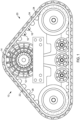
- FIG. 1 illustrates a track assembly 10 which may be used on an industrial or agricultural vehicle (not shown).
- the track assembly 10 includes a drive wheel 12 including a plurality of teeth or drive bars 14 that are positioned for mating engagement with guide lugs 16.
- the guide lugs 16 are mounted on a rubber track 20 having an endless elongate carcass.
- the endless track carcass has an outer surface 22 including a plurality of ground engaging tread lugs 24 and an inner surface 26 with a plurality of guide lugs 16, typically located on the center portion of the carcass.
- each guide lug 16 includes an elongate shaped bar with inclined drive faces 17, 19, and an upper flat face 21. The corners of the joined faces are rounded to reduce stress concentrations.
- the guide lugs 16 may also have various other shapes.
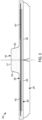
- Rubber track 20 also includes wheel path areas 27 and 29 as part of inner surface 26. Wheel path areas 27 and 29 are generally located outward from guide lugs 16. Disposed within the endless track carcass of rubber track 20 are reinforcement strips 40 and 42, beneath inner surface 26 wheel path areas 27 and 29, respectively.
- the carcass of belt 20 typically includes one or more layers of gum rubber or elastomeric material 30. Embedded within the gum rubber or elastomeric material 30 are one or more reinforcement layers 32 which extend transversely along the track width.
- the reinforcement layers 32 may comprise longitudinal cable reinforcement layers, fabric reinforcement layers, or any other reinforcement layer known to those skilled in the art.
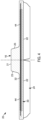
- FIG. 4 depicts an embodiment according to the disclosure where a reinforcement strip 44 extends transversely beneath inner surface 26 from wheel path area 27 to wheel path area 29.
- the reinforcement strips 40, 42 and 44 may include any suitable material, such as, but not limited to, nylon, polyester, polyethylene, polyurethane, rayon, Kevlar, aramid, metal, natural fibers such as cotton, glass fibers, carbon fibers, ceramic fibers, or plastic fibers.
- the reinforcement strip material may also be a fiber loaded rubber layer, with fibers oriented in a transverse direction or in a random direction.
- the reinforcement strip material may be tire ply made of nylon cord, steel wire, or any other suitable cord material.
- the tire cord may be bias cut applied at any suitable angle, such as +/-10, +/-20, +/-30, +/-40, +/-45, +/-50, +/-60, +/-70, +/-80, +/-90 degrees, or any point there between.
- the bias angles may be unequal; for example, but not limited to, +45/-50, -45/+50, +35/-60, etc., or the like.
- Plies used in some reinforcement strips may have equal or unequal ends per inch (epi). As an example, one ply could have 12 epi and the other ply could have 7 epi. Plies forming some reinforcing strips may be made from one material, or even several materials. For example, the plies may all be steel, or steel cord next to aramid cord (alternating). Also, plies forming some reinforcing strips could be of a merged or hybrid cord construction. For example, steel and aramid elements could be twisted together to form a cord.
- the tire cord is generally applied in two layers of opposite angles.
- the reinforcement strip material may be embedded under the track inner surface at a distance, the distance typically being in the range of about 0.020 inch to about 0.130 inch, but not necessarily limited thereto.
- the reinforcement strip(s) is covered on both sides with a skim coat layer of rubber.
- bias plies of wire treatment or fabric as a reinforcement strip in the wheel path areas of belts according to the disclosure, where the roller wheel loads are experienced can spread the loads both laterally and longitudinally and thus reduce the stress in the further underlying reinforcement layers.
- the bias ply reinforcement creates lower strain in the direction of the underlying one or more reinforcement layers 32, thus reducing heat generation.
- Table 1 below generated by Abaqus analysis, demonstrates how such lower strain transmittance by incorporation of bias reinforcement strips beneath the inner surface in wheel path areas.
- belts include reinforcement strip(s) having cords applied in two layers of opposite +/- bias angles, as described above.
- the +/- bias angles may range from about +/-20° to about +/-80°, from about +/-30° to about +/-70°, or even from about +/-40° to about +/-60°. While +/- bias angles are expressed, it should be understand that -/+ bias angles are within the scope of the disclosure, and any angle value, or range of values disclosed, will be considered +/- or -/+.
- the reinforcement strips may be incorporated into the belt during the belt manufacturing process.
- the reinforcement strip(s) is prepared independently, and prior to, the belt manufacturing process.
- the reinforcement strip(s) is/are placed as a layer beneath the inner surface of the belt prior to curing, when the belt is in a so called green state.
- the belt can be formed and vulcanized in a pressurized molding process. Some molds used in the process have shaped lug cavities which form guide lugs into their intended final shape, for track belts. Guide lugs can be presented to the final molding process as extruded pieces, which are cut to length, approximately the shape of the lug cross sectional contour. At the end they may be cut on a bias to more approximate the ends of the mold cavities.
- the lugs may be pre-molded similar to what is illustrated in U.S. Pat. No. 5,536,464 , incorporated herein by reference.
- final vulcanization occurs via imparting appropriate pressure and temperature onto the uncured belt. This is the final step in incorporating the reinforcement strip into the belt.
- a conveyor belt could have the reinforcement strip(s) incorporated inward from a pulley cover layer surface, which is opposite the load carrying upper carry cover layer surface. Such an arrangement is depicted in FIG. 6 .
- conveyor belt 50 includes an upper carry cover layer 52, a reinforcement layer 54, and pulley cover layer 56.
- the upper carry cover layer 52 is positioned above the reinforcement layer 54 (which can be constructed of a single ply or multiple plies) with the pulley cover layer 56 being positioned below the reinforcement layer 54.
- the reinforcement layer 54 is accordingly situated between the carry cover layer 52 and the pulley cover layer 56.
- the upper carry cover layer 52, reinforcement layer 54 and pulley cover layer 56 may be manufactured using materials and methods well known in the art.
- the reinforcement layer 54 may utilize a plurality of steel cables 58 (to reinforce the conveyor belt and to provide it with strength and durability.
- the reinforcement layer 54 may as an alternative to or in conjunction with the steel cables utilize fabric or polymer reinforcement components.
- the reinforcement layer 54 may be constructed of one or more plies of a polymeric fiber.
- the fabric can optionally be formed of materials such as aramid, polyester, or nylon, or any suitable mixture thereof.
- Pulley cover layer 56 has surface 60 which defines wheel path areas 62 and 64. Inward from surface 60 adjacent wheel path areas 62 and 64 are reinforcement strips 66 and 68. Reinforcement strips 66 and 68 may be designed and constructed in the manners reinforcement strips 66 and 68 disclosed above, using like materials. Also, while two reinforcement strips 66 and 68 are shown in FIG. 6 , similar to FIG. 4 above, one reinforcement strip may be utilized in some aspects.
- first, second, third, etc. may be used herein to describe various elements, components, regions, layers and/or sections, these elements, components, regions, layers and/or sections should not be limited by these terms. These terms may be only used to distinguish one element, component, region, layer or section from another region, layer or section. Terms such as “first,” “second,” and other numerical terms when used herein do not imply a sequence or order unless clearly indicated by the context. Thus, a first element, component, region, layer or section discussed below could be termed a second element, component, region, layer or section without departing from the teachings of the example embodiments.
- spatially relative terms such as “inner,” “outer,” “beneath,” “below,” “lower,” “above,” “upper,” and the like, may be used herein for ease of description to describe one element or feature's relationship to another element(s) or feature(s) as illustrated in the figures.
- Spatially relative terms may be intended to encompass different orientations of the device in use or operation in addition to the orientation depicted in the figures. For example, if the device in the figures is turned over, elements described as “below” or “beneath” other elements or features would then be oriented “above” the other elements or features.
- the example term “below” can encompass both an orientation of above and below.
- the device may be otherwise oriented (rotated 90 degrees or at other orientations) and the spatially relative descriptors used herein interpreted accordingly.
Landscapes
- Engineering & Computer Science (AREA)
- Mechanical Engineering (AREA)
- Chemical & Material Sciences (AREA)
- Combustion & Propulsion (AREA)
- Transportation (AREA)
- Tires In General (AREA)
- Belt Conveyors (AREA)
Description
- The field to which the disclosure generally relates to is belts, and more particularly, conveyor belts and endless track belts.
- This section provides background information to facilitate a better understanding of the various aspects of the disclosure. It should be understood that the statements in this section of this document are to be read in this light, and not as admissions of prior art.
- Positive drive or friction drive, endless rubber tracks such as those used on agricultural or industrial vehicles typically have wheel paths on the inner side of the tracks, which are in contact with various wheels included in a track assembly. For rubber track applications with high loads, the wheel path areas of the track have high loads exerted thereon by the supporting roller wheels. These high vertical loads create dangerously high compressive loads on the tracks internal components as well as high stress loads as the roller wheels roll along the wheel path, during the movement of the track. In some cases, this contact can cause premature wearing of the wheels, wheel path areas of the track, which can be severe, depending upon various vehicle design features and application use. Such high forces on the wheels and wheel path areas, can lead to delamination of rubber from reinforcing members within the endless track, which then may result in separation of reinforcing members from the carcass, ultimately rendering the track useless. The same can be the case for conveyor belts. Such a belt is known from
WO01/89913 - Thus, belts, such as track belts or conveyor belts, having wheel path areas which have more resistance to separation of main cables from rubber portions is desired, such need met at least in part by embodiments according to this disclosure.
- This section provides a general summary of the disclosure, and is not a necessarily a comprehensive disclosure of its full scope or all of its features.
- In a first aspect of the disclosure an endless rubber track belt is provided which includes an endless, elongate carcass having an outer surface, an inner surface, and at least one reinforcing layer. The inner surface defines a plurality of wheel path areas. A plurality of tread lugs are disposed on the outer surface. A plurality of guide lugs are disposed on the inner surface, where each guide lug includes oppositely disposed drive faces, an upper face between said drive faces, and oppositely disposed end faces. At least one reinforcement strip is disposed inward from the inner surface and outward from the at least one reinforcement layer. The at least one reinforcement strip is positioned adjacent to the plurality of wheel path areas. The at least one reinforcement strip may include a bias ply formed of two layers of cords or wires arranged in opposite +/- bias angles. The +/- bias angles may range from about +/-20° to about +/-80°. In some cases, the +/- bias angles range from about +/-30° to about +/-70°, while in other cases, the +/- bias angles range from about +/-40° to about +/-60°. In some aspects, the layers of cords are nylon tire cord. Also, the bias ply may be covered on both sides with a skim coat layer of rubber. In some aspects, the least one reinforcement strip imparts a normalized strain value of less than 0.900, or even less than 0.750.
- In another aspect of the disclosure a conveyor belt includes a reinforcement layer, a carry cover layer above the reinforcement layer, and a pulley cover layer beneath the reinforcement layer. The pulley cover layer has a surface which defines a plurality of wheel path areas. At least one reinforcement strip disposed inward from the surface of the pulley cover layer and outward from the reinforcement layer. The at least one reinforcement strip is positioned adjacent the plurality of wheel path areas. The at least one reinforcement strip may include a bias ply formed from two layers of cords arranged in opposite +/- bias angles. The +/- bias angles may range from about +/-20° to about +/-80°, from about +/-30° to about +/-70°, or even from about +/-40° to about +/-60°. In some aspects, the at least one reinforcement strip imparts a normalized strain value of less than 0.900, or even less than 0.750.
- Certain embodiments of the disclosure will hereafter be described with reference to the accompanying drawings, wherein like reference numerals denote like elements. It should be understood, however, that the accompanying figures illustrate the various implementations described herein and are not meant to limit the scope of various technologies described herein, and:
-
FIG. 1 is a side view of a track assembly according to the disclosure; -
FIG. 2 is a cut away perspective view of endless vehicle track belt according to the disclosure; -
FIG. 3 is a cross-sectional view of endless vehicle track belt according to the disclosure; -
FIG. 4 is a cross-sectional view of another endless vehicle track belt according to the disclosure; -
FIG. 5 illustrates a correlation between normalized strain values and +/bias angle for reinforcement strip(s) used in some belts according to the disclosure; and, -
FIG. 6 is a cross-sectional view of conveyor belt according to the disclosure. - The following description of the variations is merely illustrative in nature and is in no way intended to limit the scope of the disclosure, its application, or uses. The description is presented herein solely for the purpose of illustrating the various embodiments of the disclosure and should not be construed as a limitation to the scope and applicability of the disclosure. In the summary of the disclosure and this detailed description, each numerical value should be read once as modified by the term "about" (unless already expressly so modified), and then read again as not so modified unless otherwise indicated in context. Also, in the summary of the disclosure and this detailed description, it should be understood that a value range listed or described as being useful, suitable, or the like, is intended that any and every value within the range, including the end points, is to be considered as having been stated. For example, "a range of from 1 to 10" is to be read as indicating each and every possible number along the continuum between about 1 and about 10. Thus, even if specific data points within the range, or even no data points within the range, are explicitly identified or refer to only a few specific, it is to be understood that inventors appreciate and understand that any and all data points within the range are to be considered to have been specified, and that inventors had possession of the entire range and all points within the range.
- Unless expressly stated to the contrary, "or" refers to an inclusive or and not to an exclusive or. For example, a condition A or B is satisfied by anyone of the following: A is true (or present) and B is false (or not present), A is false (or not present) and B is true (or present), and both A and B are true (or present).
- In addition, use of the "a" or "an" are employed to describe elements and components of the embodiments herein. This is done merely for convenience and to give a general sense of concepts according to the disclosure. This description should be read to include one or at least one and the singular also includes the plural unless otherwise stated.
- The terminology and phraseology used herein is for descriptive purposes and should not be construed as limiting in scope. Language such as "including," "comprising," "having," "containing," or "involving," and variations thereof, is intended to be broad and encompass the subject matter listed thereafter, equivalents, and additional subject matter not recited.
- Also, as used herein any references to "one embodiment" or "an embodiment" means that a particular element, feature, structure, or characteristic described in connection with the embodiment is included in at least one embodiment. The appearances of the phrase "in one embodiment" in various places in the specification are not necessarily referring to the same embodiment.
- Embodiments according to the disclosure are generally belts having a carcass which includes an outer surface, an inner surface, and at least one reinforcing layer. The inner surface defines a plurality of wheel path areas and at least one reinforcement strip is disposed inward from the inner surface and outward from the at least one reinforcement layer. The number of reinforcement strips is not limiting, and any suitable number of reinforcement strips is within the scope of the disclosure. As such, one reinforcement strip, two reinforcement strips, four reinforcement strips, etc., could be used. The at least one reinforcement strip is positioned adjacent the plurality of wheel path areas. In some cases, the at least one reinforcement strip comprises a bias ply formed of two layers of cords arranged in opposite +/- bias angles. In some aspects the at least one reinforcement strip imparts a normalized strain value of less than 0.900.
- Now referencing
FIG. 1 , which illustrates atrack assembly 10 which may be used on an industrial or agricultural vehicle (not shown). Thetrack assembly 10 includes adrive wheel 12 including a plurality of teeth or drivebars 14 that are positioned for mating engagement with guide lugs 16. The guide lugs 16 are mounted on arubber track 20 having an endless elongate carcass. The endless track carcass has anouter surface 22 including a plurality of ground engaging tread lugs 24 and aninner surface 26 with a plurality of guide lugs 16, typically located on the center portion of the carcass. - As shown in
FIG. 2 , eachguide lug 16 includes an elongate shaped bar with inclined drive faces 17, 19, and an upperflat face 21. The corners of the joined faces are rounded to reduce stress concentrations. The guide lugs 16 may also have various other shapes.Rubber track 20 also includeswheel path areas inner surface 26.Wheel path areas rubber track 20 arereinforcement strips inner surface 26wheel path areas - As shown in
FIGS. 3 and4 , the carcass ofbelt 20 typically includes one or more layers of gum rubber orelastomeric material 30. Embedded within the gum rubber orelastomeric material 30 are one or more reinforcement layers 32 which extend transversely along the track width. The reinforcement layers 32 may comprise longitudinal cable reinforcement layers, fabric reinforcement layers, or any other reinforcement layer known to those skilled in the art.FIG. 4 depicts an embodiment according to the disclosure where areinforcement strip 44 extends transversely beneathinner surface 26 fromwheel path area 27 towheel path area 29. - The reinforcement strips 40, 42 and 44 may include any suitable material, such as, but not limited to, nylon, polyester, polyethylene, polyurethane, rayon, Kevlar, aramid, metal, natural fibers such as cotton, glass fibers, carbon fibers, ceramic fibers, or plastic fibers. The reinforcement strip material may also be a fiber loaded rubber layer, with fibers oriented in a transverse direction or in a random direction. For example, the reinforcement strip material may be tire ply made of nylon cord, steel wire, or any other suitable cord material. The tire cord may be bias cut applied at any suitable angle, such as +/-10, +/-20, +/-30, +/-40, +/-45, +/-50, +/-60, +/-70, +/-80, +/-90 degrees, or any point there between. In some aspects, the bias angles may be unequal; for example, but not limited to, +45/-50, -45/+50, +35/-60, etc., or the like.
- Plies used in some reinforcement strips may have equal or unequal ends per inch (epi). As an example, one ply could have 12 epi and the other ply could have 7 epi. Plies forming some reinforcing strips may be made from one material, or even several materials. For example, the plies may all be steel, or steel cord next to aramid cord (alternating). Also, plies forming some reinforcing strips could be of a merged or hybrid cord construction. For example, steel and aramid elements could be twisted together to form a cord.
- The tire cord is generally applied in two layers of opposite angles. As shown above, the reinforcement strip material may be embedded under the track inner surface at a distance, the distance typically being in the range of about 0.020 inch to about 0.130 inch, but not necessarily limited thereto. In some aspects, the reinforcement strip(s) is covered on both sides with a skim coat layer of rubber.
- Use of bias plies of wire treatment or fabric as a reinforcement strip in the wheel path areas of belts according to the disclosure, where the roller wheel loads are experienced can spread the loads both laterally and longitudinally and thus reduce the stress in the further underlying reinforcement layers. The bias ply reinforcement creates lower strain in the direction of the underlying one or more reinforcement layers 32, thus reducing heat generation. Table 1 below, generated by Abaqus analysis, demonstrates how such lower strain transmittance by incorporation of bias reinforcement strips beneath the inner surface in wheel path areas.
Table 1 Carcass Construction Description Strain, normalized Conventional (no reinforcement strips) 0.924 +/-10° Bias Reinforcement Strips 1.000 +/-20° Bias Reinforcement Strips 0.843 +/-40° Bias Reinforcement Strips 0.715 +/-50° Bias Reinforcement Strips 0.686 +/-60° Bias Reinforcement Strips 0.724 +/-70° Bias Reinforcement Strips 0.823 +/-80° Bias Reinforcement Strips 0.890 +/-90° Bias Reinforcement Strips 0.930 - Hence, a correlation between strain values, normalized, and +/- bias angle may be made, which is shown in
FIG. 5 . Generally, a lower strain value translates into reduced strain in the direction of the underlying one or more reinforcement layers 32, as well as reduced heat generation. In some aspects of the disclosure, belts include reinforcement strip(s) having cords applied in two layers of opposite +/- bias angles, as described above. The +/- bias angles may range from about +/-20° to about +/-80°, from about +/-30° to about +/-70°, or even from about +/-40° to about +/-60°. While +/- bias angles are expressed, it should be understand that -/+ bias angles are within the scope of the disclosure, and any angle value, or range of values disclosed, will be considered +/- or -/+. - The reinforcement strips may be incorporated into the belt during the belt manufacturing process. In such cases, the reinforcement strip(s) is prepared independently, and prior to, the belt manufacturing process. The reinforcement strip(s) is/are placed as a layer beneath the inner surface of the belt prior to curing, when the belt is in a so called green state. The belt can be formed and vulcanized in a pressurized molding process. Some molds used in the process have shaped lug cavities which form guide lugs into their intended final shape, for track belts. Guide lugs can be presented to the final molding process as extruded pieces, which are cut to length, approximately the shape of the lug cross sectional contour. At the end they may be cut on a bias to more approximate the ends of the mold cavities. Otherwise, the lugs may be pre-molded similar to what is illustrated in
U.S. Pat. No. 5,536,464 , incorporated herein by reference. After the reinforcement strip(s) has been fitted into the green belt, final vulcanization occurs via imparting appropriate pressure and temperature onto the uncured belt. This is the final step in incorporating the reinforcement strip into the belt. - While the above description illustrates some embodiments of the disclosure which are endless vehicle tracks, the same concepts could be applied to other heavy duty belts. For example, a conveyor belt could have the reinforcement strip(s) incorporated inward from a pulley cover layer surface, which is opposite the load carrying upper carry cover layer surface. Such an arrangement is depicted in
FIG. 6 . - In
FIG. 6 ,conveyor belt 50 includes an uppercarry cover layer 52, areinforcement layer 54, andpulley cover layer 56. The uppercarry cover layer 52 is positioned above the reinforcement layer 54 (which can be constructed of a single ply or multiple plies) with thepulley cover layer 56 being positioned below thereinforcement layer 54. In this fundamental design thereinforcement layer 54 is accordingly situated between thecarry cover layer 52 and thepulley cover layer 56. - The upper
carry cover layer 52,reinforcement layer 54 andpulley cover layer 56 may be manufactured using materials and methods well known in the art. Thereinforcement layer 54 may utilize a plurality of steel cables 58 (to reinforce the conveyor belt and to provide it with strength and durability. Thereinforcement layer 54 may as an alternative to or in conjunction with the steel cables utilize fabric or polymer reinforcement components. For instance, thereinforcement layer 54 may be constructed of one or more plies of a polymeric fiber. The fabric can optionally be formed of materials such as aramid, polyester, or nylon, or any suitable mixture thereof. -
Pulley cover layer 56 hassurface 60 which defineswheel path areas surface 60 adjacentwheel path areas reinforcement strips FIG. 6 , similar toFIG. 4 above, one reinforcement strip may be utilized in some aspects. - The foregoing description of the embodiments has been provided for purposes of illustration and description. Example embodiments are provided so that this disclosure will be sufficiently thorough, and will convey the scope to those who are skilled in the art. Numerous specific details are set forth such as examples of specific components, devices, and methods, to provide a thorough understanding of embodiments of the disclosure, but are not intended to be exhaustive or to limit the disclosure. It will be appreciated that it is within the scope of the disclosure that individual elements or features of a particular embodiment are generally not limited to that particular embodiment, but, where applicable, are interchangeable and can be used in a selected embodiment, even if not specifically shown or described. The same may also be varied in many ways. Such variations are not to be regarded as a departure from the disclosure, and all such modifications are intended to be included within the scope of the disclosure.
- Also, in some example embodiments, well-known processes, well-known device structures, and well-known technologies are not described in detail. Further, it will be readily apparent to those of skill in the art that in the design, manufacture, and operation of apparatus to achieve that described in the disclosure, variations in apparatus design, construction, condition, erosion of components, gaps between components may present, for example.
- Although the terms first, second, third, etc. may be used herein to describe various elements, components, regions, layers and/or sections, these elements, components, regions, layers and/or sections should not be limited by these terms. These terms may be only used to distinguish one element, component, region, layer or section from another region, layer or section. Terms such as "first," "second," and other numerical terms when used herein do not imply a sequence or order unless clearly indicated by the context. Thus, a first element, component, region, layer or section discussed below could be termed a second element, component, region, layer or section without departing from the teachings of the example embodiments.
- Spatially relative terms, such as "inner," "outer," "beneath," "below," "lower," "above," "upper," and the like, may be used herein for ease of description to describe one element or feature's relationship to another element(s) or feature(s) as illustrated in the figures. Spatially relative terms may be intended to encompass different orientations of the device in use or operation in addition to the orientation depicted in the figures. For example, if the device in the figures is turned over, elements described as "below" or "beneath" other elements or features would then be oriented "above" the other elements or features. Thus, the example term "below" can encompass both an orientation of above and below. The device may be otherwise oriented (rotated 90 degrees or at other orientations) and the spatially relative descriptors used herein interpreted accordingly.
Claims (6)
- An endless rubber track belt comprising:an endless, elongate carcass including an outer surface, an inner surface, and at least one reinforcing layer, whereinthe inner surface defines a plurality of wheel path areas;a plurality of tread lugs disposed on the outer surface;a plurality of guide lugs disposed on the inner surface, each of the plurality of guide lugs including oppositely disposed drive faces, an upper face between the drive faces, and oppositely disposed end faces; and,at least one reinforcement strip disposed inward from the inner surface and outward from the at least one reinforcement layer, wherein the at least one reinforcement strip is positioned adjacent the plurality of wheel path areas;wherein the at least one reinforcement strip comprises a bias ply comprising two layers of cords arranged in opposite +/- bias angles, and wherein the +/- bias angles range from about +/-20° to about +/-80°;wherein the bias ply is covered on both sides with a skim coat layer of rubber.
- The endless rubber track belt according to claim 1, wherein the +/- bias angles range from about +/-30° to about +/-70°.
- The endless rubber track belt according to claim 2, wherein the +/- bias angles range from about +/-40° to about +/-60°.
- The endless rubber track belt according to claim 1, wherein layers of cords comprise nylon tire cord.
- The endless rubber track belt according to claim 1, wherein the at least one reinforcement strip imparts a normalized strain value of less than 0.900.
- The endless rubber track belt according to claim 5, wherein the at least one reinforcement strip imparts a normalized strain value of less than 0.750.
Priority Applications (1)
| Application Number | Priority Date | Filing Date | Title |
|---|---|---|---|
| EP24190367.3A EP4428017A3 (en) | 2017-11-28 | 2018-11-26 | Rubber track wheel path reinforcement |
Applications Claiming Priority (2)
| Application Number | Priority Date | Filing Date | Title |
|---|---|---|---|
| US15/823,650 US10046818B1 (en) | 2017-11-28 | 2017-11-28 | Rubber track wheel path reinforcement |
| PCT/EP2018/082611 WO2019105899A1 (en) | 2017-11-28 | 2018-11-26 | Rubber track wheel path reinforcement |
Related Child Applications (1)
| Application Number | Title | Priority Date | Filing Date |
|---|---|---|---|
| EP24190367.3A Division EP4428017A3 (en) | 2017-11-28 | 2018-11-26 | Rubber track wheel path reinforcement |
Publications (2)
| Publication Number | Publication Date |
|---|---|
| EP3717336A1 EP3717336A1 (en) | 2020-10-07 |
| EP3717336B1 true EP3717336B1 (en) | 2024-07-31 |
Family
ID=63079284
Family Applications (2)
| Application Number | Title | Priority Date | Filing Date |
|---|---|---|---|
| EP24190367.3A Pending EP4428017A3 (en) | 2017-11-28 | 2018-11-26 | Rubber track wheel path reinforcement |
| EP18815119.5A Active EP3717336B1 (en) | 2017-11-28 | 2018-11-26 | Rubber track wheel path reinforcement |
Family Applications Before (1)
| Application Number | Title | Priority Date | Filing Date |
|---|---|---|---|
| EP24190367.3A Pending EP4428017A3 (en) | 2017-11-28 | 2018-11-26 | Rubber track wheel path reinforcement |
Country Status (8)
| Country | Link |
|---|---|
| US (1) | US10046818B1 (en) |
| EP (2) | EP4428017A3 (en) |
| AR (1) | AR113583A1 (en) |
| AU (1) | AU2018377964B2 (en) |
| DK (1) | DK3717336T3 (en) |
| HU (1) | HUE069083T2 (en) |
| PL (1) | PL3717336T3 (en) |
| WO (1) | WO2019105899A1 (en) |
Cited By (1)
| Publication number | Priority date | Publication date | Assignee | Title |
|---|---|---|---|---|
| RU2847216C1 (en) * | 2025-03-11 | 2025-10-01 | Акционерное Общество "Машиностроительная Компания "Витязь" | Flexible reinforced caterpillar track |
Families Citing this family (2)
| Publication number | Priority date | Publication date | Assignee | Title |
|---|---|---|---|---|
| US20160016621A1 (en) * | 2013-03-15 | 2016-01-21 | Camoplast Solideal Inc. | Endless track for traction of a vehicle |
| US11193558B2 (en) * | 2019-05-02 | 2021-12-07 | Loc Performance Products, Llc | Transmission with dual bi-directional input and single bi-directional output |
Family Cites Families (19)
| Publication number | Priority date | Publication date | Assignee | Title |
|---|---|---|---|---|
| BE791742A (en) | 1971-11-26 | 1973-05-22 | Uniroyal Inc | LENGTH CUTTING DEVICE FOR BIAS-CUT MATERIAL FOR WHEEL PNEUMATIC BANDAGE BELT TAPES |
| US3934943A (en) | 1974-03-29 | 1976-01-27 | Gage Rodney E | Endless track adapted for use with track laying vehicles |
| US4216856A (en) * | 1975-04-25 | 1980-08-12 | Dunlop Limited | Reinforcement for elastomeric articles |
| US4410082A (en) * | 1980-08-26 | 1983-10-18 | The First National Bank Of Akron | Stretchable load-retaining conveyor belt |
| US5211609A (en) * | 1992-02-06 | 1993-05-18 | The Goodyear Tire & Rubber Company | Elastomeric drive belt |
| US5536464A (en) * | 1994-11-15 | 1996-07-16 | Bridgestone/Firestone, Inc. | Apparatus and method for curing endless rubber track |
| WO2001089913A1 (en) * | 2000-05-22 | 2001-11-29 | Caterpillar Inc. | Rubber track belt with relocated circumferential cables |
| US6579930B2 (en) | 2001-02-01 | 2003-06-17 | The Goodyear Tire & Rubber Company | Tire with minimal-marking tread and skid steering, fixed axle, tire/wheel or vehicular track assembly where said tire or track has a minimal-marking tread |
| CA2390209A1 (en) | 2001-08-10 | 2003-02-10 | The Goodyear Tire & Rubber Company | Endless two part rubber track comprised of polyurethane based tread component and rubber carcass component and vehicle containing such track |
| CA2394454C (en) | 2001-09-12 | 2009-12-08 | The Goodyear Tire & Rubber Company | Cold environment endless rubber track and vehicle containing such track |
| US6764143B2 (en) * | 2002-05-09 | 2004-07-20 | The Goodyear Tire & Rubber Company | Endless elastomeric track with corrosion resistant cables |
| US7325888B2 (en) * | 2003-05-28 | 2008-02-05 | Bridgestone Corporation | Rubber crawler having excellent straight driving property |
| US20070046100A1 (en) | 2005-08-31 | 2007-03-01 | The Goodyear Tire & Rubber Company | Rubber track |
| US20070126286A1 (en) * | 2005-12-02 | 2007-06-07 | Feldmann Thomas B | Endless track belt |
| WO2007126116A1 (en) * | 2006-05-02 | 2007-11-08 | Bridgestone Corporation | Coreless rubber crawler track |
| WO2008073969A1 (en) | 2006-12-12 | 2008-06-19 | Veyance Technologies, Inc. | Endless track belt and method of making same |
| JP5189505B2 (en) * | 2007-02-05 | 2013-04-24 | 株式会社ブリヂストン | Rubber crawler |
| JP5851344B2 (en) * | 2012-05-25 | 2016-02-03 | 株式会社ブリヂストン | Rubber crawler |
| US9975590B2 (en) * | 2016-04-27 | 2018-05-22 | ContiTech Trasportbandsysteme GmbH | Vehicle track |
-
2017
- 2017-11-28 US US15/823,650 patent/US10046818B1/en active Active
-
2018
- 2018-11-26 EP EP24190367.3A patent/EP4428017A3/en active Pending
- 2018-11-26 AU AU2018377964A patent/AU2018377964B2/en active Active
- 2018-11-26 EP EP18815119.5A patent/EP3717336B1/en active Active
- 2018-11-26 DK DK18815119.5T patent/DK3717336T3/en active
- 2018-11-26 WO PCT/EP2018/082611 patent/WO2019105899A1/en not_active Ceased
- 2018-11-26 PL PL18815119.5T patent/PL3717336T3/en unknown
- 2018-11-26 HU HUE18815119A patent/HUE069083T2/en unknown
- 2018-11-27 AR ARP180103469A patent/AR113583A1/en active IP Right Grant
Cited By (1)
| Publication number | Priority date | Publication date | Assignee | Title |
|---|---|---|---|---|
| RU2847216C1 (en) * | 2025-03-11 | 2025-10-01 | Акционерное Общество "Машиностроительная Компания "Витязь" | Flexible reinforced caterpillar track |
Also Published As
| Publication number | Publication date |
|---|---|
| AU2018377964B2 (en) | 2022-04-14 |
| EP4428017A2 (en) | 2024-09-11 |
| PL3717336T3 (en) | 2024-12-16 |
| EP4428017A3 (en) | 2025-01-29 |
| AU2018377964A1 (en) | 2020-06-11 |
| WO2019105899A1 (en) | 2019-06-06 |
| DK3717336T3 (en) | 2024-08-19 |
| EP3717336A1 (en) | 2020-10-07 |
| US10046818B1 (en) | 2018-08-14 |
| HUE069083T2 (en) | 2025-02-28 |
| AR113583A1 (en) | 2020-05-20 |
Similar Documents
| Publication | Publication Date | Title |
|---|---|---|
| US20080136255A1 (en) | Endless track belt and method of making same | |
| US20070126286A1 (en) | Endless track belt | |
| EP3459763B1 (en) | Tire | |
| CN1242188C (en) | transverse reinforced CVT belt | |
| EP2070690B1 (en) | Process for manufacturing pneumatic tire | |
| EP2123483B1 (en) | Pneumatic tire | |
| US8117818B2 (en) | Steel cord, composite of rubber and steel cord, and tire | |
| EP0157716A1 (en) | Flat wire reinforcement in tyre belt and carcass | |
| AU2018377964B2 (en) | Rubber track wheel path reinforcement | |
| JP2002227937A (en) | Power transmission belt | |
| EP3173252B1 (en) | Tire | |
| CA2120686C (en) | Cut resistant tire | |
| EP3459762A1 (en) | Tire | |
| EP3279010A1 (en) | Cord-rubber composite and pneumatic tire | |
| WO2015058016A1 (en) | Tire apex structure | |
| US3181690A (en) | Segmental conveyor belt | |
| EP3299180A1 (en) | Pneumatic tire | |
| EP3042788B1 (en) | Cap ply for pneumatic tire and method of manufacturing cap ply for pneumatic tire | |
| EP3081395A1 (en) | A continuous crown reinforcement for a pneumatic tire | |
| CA2568585A1 (en) | Improved endless track belt | |
| KR101242283B1 (en) | Rubber crawler | |
| JP2015009903A (en) | Belt for pipe conveyor | |
| KR101742983B1 (en) | Steel cord for reinforcing rubber and radial tire | |
| KR101341191B1 (en) | Radial tire for heavy duty vehicle | |
| JP2002321667A (en) | Elastic crawler |
Legal Events
| Date | Code | Title | Description |
|---|---|---|---|
| STAA | Information on the status of an ep patent application or granted ep patent |
Free format text: STATUS: UNKNOWN |
|
| STAA | Information on the status of an ep patent application or granted ep patent |
Free format text: STATUS: THE INTERNATIONAL PUBLICATION HAS BEEN MADE |
|
| PUAI | Public reference made under article 153(3) epc to a published international application that has entered the european phase |
Free format text: ORIGINAL CODE: 0009012 |
|
| STAA | Information on the status of an ep patent application or granted ep patent |
Free format text: STATUS: REQUEST FOR EXAMINATION WAS MADE |
|
| 17P | Request for examination filed |
Effective date: 20200629 |
|
| AK | Designated contracting states |
Kind code of ref document: A1 Designated state(s): AL AT BE BG CH CY CZ DE DK EE ES FI FR GB GR HR HU IE IS IT LI LT LU LV MC MK MT NL NO PL PT RO RS SE SI SK SM TR |
|
| AX | Request for extension of the european patent |
Extension state: BA ME |
|
| RAP1 | Party data changed (applicant data changed or rights of an application transferred) |
Owner name: CONTITECH TRANSPORTBANDSYSTEME GMBH |
|
| DAV | Request for validation of the european patent (deleted) | ||
| DAX | Request for extension of the european patent (deleted) | ||
| STAA | Information on the status of an ep patent application or granted ep patent |
Free format text: STATUS: EXAMINATION IS IN PROGRESS |
|
| 17Q | First examination report despatched |
Effective date: 20220307 |
|
| RAP1 | Party data changed (applicant data changed or rights of an application transferred) |
Owner name: LOC PERFORMANCE PRODUCTS, LLC |
|
| RAP1 | Party data changed (applicant data changed or rights of an application transferred) |
Owner name: LOC PERFORMANCE PRODUCTS, LLC |
|
| GRAP | Despatch of communication of intention to grant a patent |
Free format text: ORIGINAL CODE: EPIDOSNIGR1 |
|
| STAA | Information on the status of an ep patent application or granted ep patent |
Free format text: STATUS: GRANT OF PATENT IS INTENDED |
|
| INTG | Intention to grant announced |
Effective date: 20240319 |
|
| GRAS | Grant fee paid |
Free format text: ORIGINAL CODE: EPIDOSNIGR3 |
|
| GRAA | (expected) grant |
Free format text: ORIGINAL CODE: 0009210 |
|
| STAA | Information on the status of an ep patent application or granted ep patent |
Free format text: STATUS: THE PATENT HAS BEEN GRANTED |
|
| AK | Designated contracting states |
Kind code of ref document: B1 Designated state(s): AL AT BE BG CH CY CZ DE DK EE ES FI FR GB GR HR HU IE IS IT LI LT LU LV MC MK MT NL NO PL PT RO RS SE SI SK SM TR |
|
| REG | Reference to a national code |
Ref country code: CH Ref legal event code: EP Ref country code: GB Ref legal event code: FG4D |
|
| REG | Reference to a national code |
Ref country code: DE Ref legal event code: R096 Ref document number: 602018072503 Country of ref document: DE |
|
| REG | Reference to a national code |
Ref country code: DK Ref legal event code: T3 Effective date: 20240813 |
|
| P01 | Opt-out of the competence of the unified patent court (upc) registered |
Free format text: CASE NUMBER: APP_42128/2024 Effective date: 20240717 |
|
| REG | Reference to a national code |
Ref country code: IE Ref legal event code: FG4D |
|
| REG | Reference to a national code |
Ref country code: LT Ref legal event code: MG9D |
|
| REG | Reference to a national code |
Ref country code: NL Ref legal event code: MP Effective date: 20240731 |
|
| PG25 | Lapsed in a contracting state [announced via postgrant information from national office to epo] |
Ref country code: PT Free format text: LAPSE BECAUSE OF FAILURE TO SUBMIT A TRANSLATION OF THE DESCRIPTION OR TO PAY THE FEE WITHIN THE PRESCRIBED TIME-LIMIT Effective date: 20241202 |
|
| REG | Reference to a national code |
Ref country code: AT Ref legal event code: MK05 Ref document number: 1708227 Country of ref document: AT Kind code of ref document: T Effective date: 20240731 |
|
| PG25 | Lapsed in a contracting state [announced via postgrant information from national office to epo] |
Ref country code: PT Free format text: LAPSE BECAUSE OF FAILURE TO SUBMIT A TRANSLATION OF THE DESCRIPTION OR TO PAY THE FEE WITHIN THE PRESCRIBED TIME-LIMIT Effective date: 20241202 |
|
| PG25 | Lapsed in a contracting state [announced via postgrant information from national office to epo] |
Ref country code: NO Free format text: LAPSE BECAUSE OF FAILURE TO SUBMIT A TRANSLATION OF THE DESCRIPTION OR TO PAY THE FEE WITHIN THE PRESCRIBED TIME-LIMIT Effective date: 20241031 |
|
| PG25 | Lapsed in a contracting state [announced via postgrant information from national office to epo] |
Ref country code: FI Free format text: LAPSE BECAUSE OF FAILURE TO SUBMIT A TRANSLATION OF THE DESCRIPTION OR TO PAY THE FEE WITHIN THE PRESCRIBED TIME-LIMIT Effective date: 20240731 Ref country code: NL Free format text: LAPSE BECAUSE OF FAILURE TO SUBMIT A TRANSLATION OF THE DESCRIPTION OR TO PAY THE FEE WITHIN THE PRESCRIBED TIME-LIMIT Effective date: 20240731 Ref country code: GR Free format text: LAPSE BECAUSE OF FAILURE TO SUBMIT A TRANSLATION OF THE DESCRIPTION OR TO PAY THE FEE WITHIN THE PRESCRIBED TIME-LIMIT Effective date: 20241101 |
|
| PG25 | Lapsed in a contracting state [announced via postgrant information from national office to epo] |
Ref country code: LV Free format text: LAPSE BECAUSE OF FAILURE TO SUBMIT A TRANSLATION OF THE DESCRIPTION OR TO PAY THE FEE WITHIN THE PRESCRIBED TIME-LIMIT Effective date: 20240731 |
|
| PG25 | Lapsed in a contracting state [announced via postgrant information from national office to epo] |
Ref country code: IS Free format text: LAPSE BECAUSE OF FAILURE TO SUBMIT A TRANSLATION OF THE DESCRIPTION OR TO PAY THE FEE WITHIN THE PRESCRIBED TIME-LIMIT Effective date: 20241130 Ref country code: AT Free format text: LAPSE BECAUSE OF FAILURE TO SUBMIT A TRANSLATION OF THE DESCRIPTION OR TO PAY THE FEE WITHIN THE PRESCRIBED TIME-LIMIT Effective date: 20240731 |
|
| PG25 | Lapsed in a contracting state [announced via postgrant information from national office to epo] |
Ref country code: HR Free format text: LAPSE BECAUSE OF FAILURE TO SUBMIT A TRANSLATION OF THE DESCRIPTION OR TO PAY THE FEE WITHIN THE PRESCRIBED TIME-LIMIT Effective date: 20240731 |
|
| PG25 | Lapsed in a contracting state [announced via postgrant information from national office to epo] |
Ref country code: RS Free format text: LAPSE BECAUSE OF FAILURE TO SUBMIT A TRANSLATION OF THE DESCRIPTION OR TO PAY THE FEE WITHIN THE PRESCRIBED TIME-LIMIT Effective date: 20241031 Ref country code: ES Free format text: LAPSE BECAUSE OF FAILURE TO SUBMIT A TRANSLATION OF THE DESCRIPTION OR TO PAY THE FEE WITHIN THE PRESCRIBED TIME-LIMIT Effective date: 20240731 |
|
| PG25 | Lapsed in a contracting state [announced via postgrant information from national office to epo] |
Ref country code: RS Free format text: LAPSE BECAUSE OF FAILURE TO SUBMIT A TRANSLATION OF THE DESCRIPTION OR TO PAY THE FEE WITHIN THE PRESCRIBED TIME-LIMIT Effective date: 20241031 Ref country code: NO Free format text: LAPSE BECAUSE OF FAILURE TO SUBMIT A TRANSLATION OF THE DESCRIPTION OR TO PAY THE FEE WITHIN THE PRESCRIBED TIME-LIMIT Effective date: 20241031 Ref country code: NL Free format text: LAPSE BECAUSE OF FAILURE TO SUBMIT A TRANSLATION OF THE DESCRIPTION OR TO PAY THE FEE WITHIN THE PRESCRIBED TIME-LIMIT Effective date: 20240731 Ref country code: LV Free format text: LAPSE BECAUSE OF FAILURE TO SUBMIT A TRANSLATION OF THE DESCRIPTION OR TO PAY THE FEE WITHIN THE PRESCRIBED TIME-LIMIT Effective date: 20240731 Ref country code: IS Free format text: LAPSE BECAUSE OF FAILURE TO SUBMIT A TRANSLATION OF THE DESCRIPTION OR TO PAY THE FEE WITHIN THE PRESCRIBED TIME-LIMIT Effective date: 20241130 Ref country code: HR Free format text: LAPSE BECAUSE OF FAILURE TO SUBMIT A TRANSLATION OF THE DESCRIPTION OR TO PAY THE FEE WITHIN THE PRESCRIBED TIME-LIMIT Effective date: 20240731 Ref country code: GR Free format text: LAPSE BECAUSE OF FAILURE TO SUBMIT A TRANSLATION OF THE DESCRIPTION OR TO PAY THE FEE WITHIN THE PRESCRIBED TIME-LIMIT Effective date: 20241101 Ref country code: FI Free format text: LAPSE BECAUSE OF FAILURE TO SUBMIT A TRANSLATION OF THE DESCRIPTION OR TO PAY THE FEE WITHIN THE PRESCRIBED TIME-LIMIT Effective date: 20240731 Ref country code: ES Free format text: LAPSE BECAUSE OF FAILURE TO SUBMIT A TRANSLATION OF THE DESCRIPTION OR TO PAY THE FEE WITHIN THE PRESCRIBED TIME-LIMIT Effective date: 20240731 Ref country code: AT Free format text: LAPSE BECAUSE OF FAILURE TO SUBMIT A TRANSLATION OF THE DESCRIPTION OR TO PAY THE FEE WITHIN THE PRESCRIBED TIME-LIMIT Effective date: 20240731 |
|
| REG | Reference to a national code |
Ref country code: HU Ref legal event code: AG4A Ref document number: E069083 Country of ref document: HU |
|
| PG25 | Lapsed in a contracting state [announced via postgrant information from national office to epo] |
Ref country code: SM Free format text: LAPSE BECAUSE OF FAILURE TO SUBMIT A TRANSLATION OF THE DESCRIPTION OR TO PAY THE FEE WITHIN THE PRESCRIBED TIME-LIMIT Effective date: 20240731 Ref country code: RO Free format text: LAPSE BECAUSE OF FAILURE TO SUBMIT A TRANSLATION OF THE DESCRIPTION OR TO PAY THE FEE WITHIN THE PRESCRIBED TIME-LIMIT Effective date: 20240731 |
|
| PG25 | Lapsed in a contracting state [announced via postgrant information from national office to epo] |
Ref country code: EE Free format text: LAPSE BECAUSE OF FAILURE TO SUBMIT A TRANSLATION OF THE DESCRIPTION OR TO PAY THE FEE WITHIN THE PRESCRIBED TIME-LIMIT Effective date: 20240731 |
|
| PG25 | Lapsed in a contracting state [announced via postgrant information from national office to epo] |
Ref country code: SK Free format text: LAPSE BECAUSE OF FAILURE TO SUBMIT A TRANSLATION OF THE DESCRIPTION OR TO PAY THE FEE WITHIN THE PRESCRIBED TIME-LIMIT Effective date: 20240731 |
|
| REG | Reference to a national code |
Ref country code: DE Ref legal event code: R097 Ref document number: 602018072503 Country of ref document: DE |
|
| PLBE | No opposition filed within time limit |
Free format text: ORIGINAL CODE: 0009261 |
|
| STAA | Information on the status of an ep patent application or granted ep patent |
Free format text: STATUS: NO OPPOSITION FILED WITHIN TIME LIMIT |
|
| REG | Reference to a national code |
Ref country code: CH Ref legal event code: PL |
|
| PG25 | Lapsed in a contracting state [announced via postgrant information from national office to epo] |
Ref country code: MC Free format text: LAPSE BECAUSE OF FAILURE TO SUBMIT A TRANSLATION OF THE DESCRIPTION OR TO PAY THE FEE WITHIN THE PRESCRIBED TIME-LIMIT Effective date: 20240731 |
|
| 26N | No opposition filed |
Effective date: 20250501 |
|
| PG25 | Lapsed in a contracting state [announced via postgrant information from national office to epo] |
Ref country code: LU Free format text: LAPSE BECAUSE OF NON-PAYMENT OF DUE FEES Effective date: 20241126 |
|
| REG | Reference to a national code |
Ref country code: CH Ref legal event code: PL |
|
| PG25 | Lapsed in a contracting state [announced via postgrant information from national office to epo] |
Ref country code: CH Free format text: LAPSE BECAUSE OF NON-PAYMENT OF DUE FEES Effective date: 20241130 |
|
| PG25 | Lapsed in a contracting state [announced via postgrant information from national office to epo] |
Ref country code: SE Free format text: LAPSE BECAUSE OF FAILURE TO SUBMIT A TRANSLATION OF THE DESCRIPTION OR TO PAY THE FEE WITHIN THE PRESCRIBED TIME-LIMIT Effective date: 20240731 |
|
| PG25 | Lapsed in a contracting state [announced via postgrant information from national office to epo] |
Ref country code: IE Free format text: LAPSE BECAUSE OF NON-PAYMENT OF DUE FEES Effective date: 20241126 |
|
| PGFP | Annual fee paid to national office [announced via postgrant information from national office to epo] |
Ref country code: HU Payment date: 20251107 Year of fee payment: 8 |
|
| PGFP | Annual fee paid to national office [announced via postgrant information from national office to epo] |
Ref country code: DE Payment date: 20251128 Year of fee payment: 8 |
|
| PGFP | Annual fee paid to national office [announced via postgrant information from national office to epo] |
Ref country code: GB Payment date: 20251125 Year of fee payment: 8 |
|
| PGFP | Annual fee paid to national office [announced via postgrant information from national office to epo] |
Ref country code: IT Payment date: 20251127 Year of fee payment: 8 Ref country code: DK Payment date: 20251126 Year of fee payment: 8 |
|
| PGFP | Annual fee paid to national office [announced via postgrant information from national office to epo] |
Ref country code: FR Payment date: 20251128 Year of fee payment: 8 |
|
| PGFP | Annual fee paid to national office [announced via postgrant information from national office to epo] |
Ref country code: BE Payment date: 20251125 Year of fee payment: 8 |
|
| PGFP | Annual fee paid to national office [announced via postgrant information from national office to epo] |
Ref country code: CZ Payment date: 20251031 Year of fee payment: 8 |
|
| PGFP | Annual fee paid to national office [announced via postgrant information from national office to epo] |
Ref country code: PL Payment date: 20251105 Year of fee payment: 8 Ref country code: BG Payment date: 20251128 Year of fee payment: 8 |
|
| PG25 | Lapsed in a contracting state [announced via postgrant information from national office to epo] |
Ref country code: CY Free format text: LAPSE BECAUSE OF FAILURE TO SUBMIT A TRANSLATION OF THE DESCRIPTION OR TO PAY THE FEE WITHIN THE PRESCRIBED TIME-LIMIT; INVALID AB INITIO Effective date: 20181126 |