EP3717301B1 - Device for removal of heat from a plurality of heat sources - Google Patents
Device for removal of heat from a plurality of heat sources Download PDFInfo
- Publication number
- EP3717301B1 EP3717301B1 EP18882547.5A EP18882547A EP3717301B1 EP 3717301 B1 EP3717301 B1 EP 3717301B1 EP 18882547 A EP18882547 A EP 18882547A EP 3717301 B1 EP3717301 B1 EP 3717301B1
- Authority
- EP
- European Patent Office
- Prior art keywords
- intermediate frame
- manifold
- elongated intermediate
- frame member
- frame members
- Prior art date
- Legal status (The legal status is an assumption and is not a legal conclusion. Google has not performed a legal analysis and makes no representation as to the accuracy of the status listed.)
- Active
Links
Images






Classifications
-
- H—ELECTRICITY
- H01—ELECTRIC ELEMENTS
- H01M—PROCESSES OR MEANS, e.g. BATTERIES, FOR THE DIRECT CONVERSION OF CHEMICAL ENERGY INTO ELECTRICAL ENERGY
- H01M10/00—Secondary cells; Manufacture thereof
- H01M10/60—Heating or cooling; Temperature control
- H01M10/65—Means for temperature control structurally associated with the cells
- H01M10/655—Solid structures for heat exchange or heat conduction
- H01M10/6556—Solid parts with flow channel passages or pipes for heat exchange
- H01M10/6557—Solid parts with flow channel passages or pipes for heat exchange arranged between the cells
-
- B—PERFORMING OPERATIONS; TRANSPORTING
- B60—VEHICLES IN GENERAL
- B60L—PROPULSION OF ELECTRICALLY-PROPELLED VEHICLES; SUPPLYING ELECTRIC POWER FOR AUXILIARY EQUIPMENT OF ELECTRICALLY-PROPELLED VEHICLES; ELECTRODYNAMIC BRAKE SYSTEMS FOR VEHICLES IN GENERAL; MAGNETIC SUSPENSION OR LEVITATION FOR VEHICLES; MONITORING OPERATING VARIABLES OF ELECTRICALLY-PROPELLED VEHICLES; ELECTRIC SAFETY DEVICES FOR ELECTRICALLY-PROPELLED VEHICLES
- B60L50/00—Electric propulsion with power supplied within the vehicle
- B60L50/50—Electric propulsion with power supplied within the vehicle using propulsion power supplied by batteries or fuel cells
- B60L50/60—Electric propulsion with power supplied within the vehicle using propulsion power supplied by batteries or fuel cells using power supplied by batteries
- B60L50/64—Constructional details of batteries specially adapted for electric vehicles
-
- B—PERFORMING OPERATIONS; TRANSPORTING
- B60—VEHICLES IN GENERAL
- B60L—PROPULSION OF ELECTRICALLY-PROPELLED VEHICLES; SUPPLYING ELECTRIC POWER FOR AUXILIARY EQUIPMENT OF ELECTRICALLY-PROPELLED VEHICLES; ELECTRODYNAMIC BRAKE SYSTEMS FOR VEHICLES IN GENERAL; MAGNETIC SUSPENSION OR LEVITATION FOR VEHICLES; MONITORING OPERATING VARIABLES OF ELECTRICALLY-PROPELLED VEHICLES; ELECTRIC SAFETY DEVICES FOR ELECTRICALLY-PROPELLED VEHICLES
- B60L58/00—Methods or circuit arrangements for monitoring or controlling batteries or fuel cells, specially adapted for electric vehicles
- B60L58/10—Methods or circuit arrangements for monitoring or controlling batteries or fuel cells, specially adapted for electric vehicles for monitoring or controlling batteries
- B60L58/24—Methods or circuit arrangements for monitoring or controlling batteries or fuel cells, specially adapted for electric vehicles for monitoring or controlling batteries for controlling the temperature of batteries
- B60L58/26—Methods or circuit arrangements for monitoring or controlling batteries or fuel cells, specially adapted for electric vehicles for monitoring or controlling batteries for controlling the temperature of batteries by cooling
-
- F—MECHANICAL ENGINEERING; LIGHTING; HEATING; WEAPONS; BLASTING
- F28—HEAT EXCHANGE IN GENERAL
- F28D—HEAT-EXCHANGE APPARATUS, NOT PROVIDED FOR IN ANOTHER SUBCLASS, IN WHICH THE HEAT-EXCHANGE MEDIA DO NOT COME INTO DIRECT CONTACT
- F28D1/00—Heat-exchange apparatus having stationary conduit assemblies for one heat-exchange medium only, the media being in contact with different sides of the conduit wall, in which the other heat-exchange medium is a large body of fluid, e.g. domestic or motor car radiators
- F28D1/02—Heat-exchange apparatus having stationary conduit assemblies for one heat-exchange medium only, the media being in contact with different sides of the conduit wall, in which the other heat-exchange medium is a large body of fluid, e.g. domestic or motor car radiators with heat-exchange conduits immersed in the body of fluid
- F28D1/04—Heat-exchange apparatus having stationary conduit assemblies for one heat-exchange medium only, the media being in contact with different sides of the conduit wall, in which the other heat-exchange medium is a large body of fluid, e.g. domestic or motor car radiators with heat-exchange conduits immersed in the body of fluid with tubular conduits
- F28D1/053—Heat-exchange apparatus having stationary conduit assemblies for one heat-exchange medium only, the media being in contact with different sides of the conduit wall, in which the other heat-exchange medium is a large body of fluid, e.g. domestic or motor car radiators with heat-exchange conduits immersed in the body of fluid with tubular conduits the conduits being straight
- F28D1/05316—Assemblies of conduits connected to common headers, e.g. core type radiators
-
- F—MECHANICAL ENGINEERING; LIGHTING; HEATING; WEAPONS; BLASTING
- F28—HEAT EXCHANGE IN GENERAL
- F28D—HEAT-EXCHANGE APPARATUS, NOT PROVIDED FOR IN ANOTHER SUBCLASS, IN WHICH THE HEAT-EXCHANGE MEDIA DO NOT COME INTO DIRECT CONTACT
- F28D1/00—Heat-exchange apparatus having stationary conduit assemblies for one heat-exchange medium only, the media being in contact with different sides of the conduit wall, in which the other heat-exchange medium is a large body of fluid, e.g. domestic or motor car radiators
- F28D1/02—Heat-exchange apparatus having stationary conduit assemblies for one heat-exchange medium only, the media being in contact with different sides of the conduit wall, in which the other heat-exchange medium is a large body of fluid, e.g. domestic or motor car radiators with heat-exchange conduits immersed in the body of fluid
- F28D1/04—Heat-exchange apparatus having stationary conduit assemblies for one heat-exchange medium only, the media being in contact with different sides of the conduit wall, in which the other heat-exchange medium is a large body of fluid, e.g. domestic or motor car radiators with heat-exchange conduits immersed in the body of fluid with tubular conduits
- F28D1/053—Heat-exchange apparatus having stationary conduit assemblies for one heat-exchange medium only, the media being in contact with different sides of the conduit wall, in which the other heat-exchange medium is a large body of fluid, e.g. domestic or motor car radiators with heat-exchange conduits immersed in the body of fluid with tubular conduits the conduits being straight
- F28D1/0535—Heat-exchange apparatus having stationary conduit assemblies for one heat-exchange medium only, the media being in contact with different sides of the conduit wall, in which the other heat-exchange medium is a large body of fluid, e.g. domestic or motor car radiators with heat-exchange conduits immersed in the body of fluid with tubular conduits the conduits being straight the conduits having a non-circular cross-section
- F28D1/05366—Assemblies of conduits connected to common headers, e.g. core type radiators
-
- F—MECHANICAL ENGINEERING; LIGHTING; HEATING; WEAPONS; BLASTING
- F28—HEAT EXCHANGE IN GENERAL
- F28F—DETAILS OF HEAT-EXCHANGE AND HEAT-TRANSFER APPARATUS, OF GENERAL APPLICATION
- F28F1/00—Tubular elements; Assemblies of tubular elements
- F28F1/02—Tubular elements of cross-section which is non-circular
-
- F—MECHANICAL ENGINEERING; LIGHTING; HEATING; WEAPONS; BLASTING
- F28—HEAT EXCHANGE IN GENERAL
- F28F—DETAILS OF HEAT-EXCHANGE AND HEAT-TRANSFER APPARATUS, OF GENERAL APPLICATION
- F28F1/00—Tubular elements; Assemblies of tubular elements
- F28F1/10—Tubular elements and assemblies thereof with means for increasing heat-transfer area, e.g. with fins, with projections, with recesses
- F28F1/12—Tubular elements and assemblies thereof with means for increasing heat-transfer area, e.g. with fins, with projections, with recesses the means being only outside the tubular element
- F28F1/14—Tubular elements and assemblies thereof with means for increasing heat-transfer area, e.g. with fins, with projections, with recesses the means being only outside the tubular element and extending longitudinally
- F28F1/16—Tubular elements and assemblies thereof with means for increasing heat-transfer area, e.g. with fins, with projections, with recesses the means being only outside the tubular element and extending longitudinally the means being integral with the element, e.g. formed by extrusion
-
- F—MECHANICAL ENGINEERING; LIGHTING; HEATING; WEAPONS; BLASTING
- F28—HEAT EXCHANGE IN GENERAL
- F28F—DETAILS OF HEAT-EXCHANGE AND HEAT-TRANSFER APPARATUS, OF GENERAL APPLICATION
- F28F1/00—Tubular elements; Assemblies of tubular elements
- F28F1/10—Tubular elements and assemblies thereof with means for increasing heat-transfer area, e.g. with fins, with projections, with recesses
- F28F1/12—Tubular elements and assemblies thereof with means for increasing heat-transfer area, e.g. with fins, with projections, with recesses the means being only outside the tubular element
- F28F1/14—Tubular elements and assemblies thereof with means for increasing heat-transfer area, e.g. with fins, with projections, with recesses the means being only outside the tubular element and extending longitudinally
- F28F1/20—Tubular elements and assemblies thereof with means for increasing heat-transfer area, e.g. with fins, with projections, with recesses the means being only outside the tubular element and extending longitudinally the means being attachable to the element
-
- F—MECHANICAL ENGINEERING; LIGHTING; HEATING; WEAPONS; BLASTING
- F28—HEAT EXCHANGE IN GENERAL
- F28F—DETAILS OF HEAT-EXCHANGE AND HEAT-TRANSFER APPARATUS, OF GENERAL APPLICATION
- F28F1/00—Tubular elements; Assemblies of tubular elements
- F28F1/10—Tubular elements and assemblies thereof with means for increasing heat-transfer area, e.g. with fins, with projections, with recesses
- F28F1/12—Tubular elements and assemblies thereof with means for increasing heat-transfer area, e.g. with fins, with projections, with recesses the means being only outside the tubular element
- F28F1/14—Tubular elements and assemblies thereof with means for increasing heat-transfer area, e.g. with fins, with projections, with recesses the means being only outside the tubular element and extending longitudinally
- F28F1/22—Tubular elements and assemblies thereof with means for increasing heat-transfer area, e.g. with fins, with projections, with recesses the means being only outside the tubular element and extending longitudinally the means having portions engaging further tubular elements
-
- F—MECHANICAL ENGINEERING; LIGHTING; HEATING; WEAPONS; BLASTING
- F28—HEAT EXCHANGE IN GENERAL
- F28F—DETAILS OF HEAT-EXCHANGE AND HEAT-TRANSFER APPARATUS, OF GENERAL APPLICATION
- F28F3/00—Plate-like or laminated elements; Assemblies of plate-like or laminated elements
- F28F3/12—Elements constructed in the shape of a hollow panel, e.g. with channels
-
- F—MECHANICAL ENGINEERING; LIGHTING; HEATING; WEAPONS; BLASTING
- F28—HEAT EXCHANGE IN GENERAL
- F28F—DETAILS OF HEAT-EXCHANGE AND HEAT-TRANSFER APPARATUS, OF GENERAL APPLICATION
- F28F9/00—Casings; Header boxes; Auxiliary supports for elements; Auxiliary members within casings
- F28F9/02—Header boxes; End plates
-
- F—MECHANICAL ENGINEERING; LIGHTING; HEATING; WEAPONS; BLASTING
- F28—HEAT EXCHANGE IN GENERAL
- F28F—DETAILS OF HEAT-EXCHANGE AND HEAT-TRANSFER APPARATUS, OF GENERAL APPLICATION
- F28F9/00—Casings; Header boxes; Auxiliary supports for elements; Auxiliary members within casings
- F28F9/02—Header boxes; End plates
- F28F9/04—Arrangements for sealing elements into header boxes or end plates
- F28F9/16—Arrangements for sealing elements into header boxes or end plates by permanent joints, e.g. by rolling
-
- F—MECHANICAL ENGINEERING; LIGHTING; HEATING; WEAPONS; BLASTING
- F28—HEAT EXCHANGE IN GENERAL
- F28F—DETAILS OF HEAT-EXCHANGE AND HEAT-TRANSFER APPARATUS, OF GENERAL APPLICATION
- F28F9/00—Casings; Header boxes; Auxiliary supports for elements; Auxiliary members within casings
- F28F9/02—Header boxes; End plates
- F28F9/04—Arrangements for sealing elements into header boxes or end plates
- F28F9/16—Arrangements for sealing elements into header boxes or end plates by permanent joints, e.g. by rolling
- F28F9/162—Arrangements for sealing elements into header boxes or end plates by permanent joints, e.g. by rolling by using bonding or sealing substances, e.g. adhesives
-
- F—MECHANICAL ENGINEERING; LIGHTING; HEATING; WEAPONS; BLASTING
- F28—HEAT EXCHANGE IN GENERAL
- F28F—DETAILS OF HEAT-EXCHANGE AND HEAT-TRANSFER APPARATUS, OF GENERAL APPLICATION
- F28F9/00—Casings; Header boxes; Auxiliary supports for elements; Auxiliary members within casings
- F28F9/02—Header boxes; End plates
- F28F9/04—Arrangements for sealing elements into header boxes or end plates
- F28F9/16—Arrangements for sealing elements into header boxes or end plates by permanent joints, e.g. by rolling
- F28F9/18—Arrangements for sealing elements into header boxes or end plates by permanent joints, e.g. by rolling by welding
- F28F9/182—Arrangements for sealing elements into header boxes or end plates by permanent joints, e.g. by rolling by welding the heat-exchange conduits having ends with a particular shape, e.g. deformed; the heat-exchange conduits or end plates having supplementary joining means, e.g. abutments
-
- H—ELECTRICITY
- H01—ELECTRIC ELEMENTS
- H01M—PROCESSES OR MEANS, e.g. BATTERIES, FOR THE DIRECT CONVERSION OF CHEMICAL ENERGY INTO ELECTRICAL ENERGY
- H01M10/00—Secondary cells; Manufacture thereof
- H01M10/60—Heating or cooling; Temperature control
- H01M10/61—Types of temperature control
- H01M10/613—Cooling or keeping cold
-
- H—ELECTRICITY
- H01—ELECTRIC ELEMENTS
- H01M—PROCESSES OR MEANS, e.g. BATTERIES, FOR THE DIRECT CONVERSION OF CHEMICAL ENERGY INTO ELECTRICAL ENERGY
- H01M10/00—Secondary cells; Manufacture thereof
- H01M10/60—Heating or cooling; Temperature control
- H01M10/61—Types of temperature control
- H01M10/615—Heating or keeping warm
-
- H—ELECTRICITY
- H01—ELECTRIC ELEMENTS
- H01M—PROCESSES OR MEANS, e.g. BATTERIES, FOR THE DIRECT CONVERSION OF CHEMICAL ENERGY INTO ELECTRICAL ENERGY
- H01M10/00—Secondary cells; Manufacture thereof
- H01M10/60—Heating or cooling; Temperature control
- H01M10/64—Heating or cooling; Temperature control characterised by the shape of the cells
- H01M10/647—Prismatic or flat cells, e.g. pouch cells
-
- H—ELECTRICITY
- H01—ELECTRIC ELEMENTS
- H01M—PROCESSES OR MEANS, e.g. BATTERIES, FOR THE DIRECT CONVERSION OF CHEMICAL ENERGY INTO ELECTRICAL ENERGY
- H01M10/00—Secondary cells; Manufacture thereof
- H01M10/60—Heating or cooling; Temperature control
- H01M10/65—Means for temperature control structurally associated with the cells
- H01M10/655—Solid structures for heat exchange or heat conduction
- H01M10/6556—Solid parts with flow channel passages or pipes for heat exchange
-
- F—MECHANICAL ENGINEERING; LIGHTING; HEATING; WEAPONS; BLASTING
- F28—HEAT EXCHANGE IN GENERAL
- F28D—HEAT-EXCHANGE APPARATUS, NOT PROVIDED FOR IN ANOTHER SUBCLASS, IN WHICH THE HEAT-EXCHANGE MEDIA DO NOT COME INTO DIRECT CONTACT
- F28D21/00—Heat-exchange apparatus not covered by any of the groups F28D1/00 - F28D20/00
- F28D2021/0019—Other heat exchangers for particular applications; Heat exchange systems not otherwise provided for
- F28D2021/0028—Other heat exchangers for particular applications; Heat exchange systems not otherwise provided for for cooling heat generating elements, e.g. for cooling electronic components or electric devices
-
- F—MECHANICAL ENGINEERING; LIGHTING; HEATING; WEAPONS; BLASTING
- F28—HEAT EXCHANGE IN GENERAL
- F28F—DETAILS OF HEAT-EXCHANGE AND HEAT-TRANSFER APPARATUS, OF GENERAL APPLICATION
- F28F2260/00—Heat exchangers or heat exchange elements having special size, e.g. microstructures
- F28F2260/02—Heat exchangers or heat exchange elements having special size, e.g. microstructures having microchannels
-
- F—MECHANICAL ENGINEERING; LIGHTING; HEATING; WEAPONS; BLASTING
- F28—HEAT EXCHANGE IN GENERAL
- F28F—DETAILS OF HEAT-EXCHANGE AND HEAT-TRANSFER APPARATUS, OF GENERAL APPLICATION
- F28F2275/00—Fastening; Joining
- F28F2275/02—Fastening; Joining by using bonding materials; by embedding elements in particular materials
-
- F—MECHANICAL ENGINEERING; LIGHTING; HEATING; WEAPONS; BLASTING
- F28—HEAT EXCHANGE IN GENERAL
- F28F—DETAILS OF HEAT-EXCHANGE AND HEAT-TRANSFER APPARATUS, OF GENERAL APPLICATION
- F28F2275/00—Fastening; Joining
- F28F2275/04—Fastening; Joining by brazing
-
- F—MECHANICAL ENGINEERING; LIGHTING; HEATING; WEAPONS; BLASTING
- F28—HEAT EXCHANGE IN GENERAL
- F28F—DETAILS OF HEAT-EXCHANGE AND HEAT-TRANSFER APPARATUS, OF GENERAL APPLICATION
- F28F2275/00—Fastening; Joining
- F28F2275/06—Fastening; Joining by welding
-
- F—MECHANICAL ENGINEERING; LIGHTING; HEATING; WEAPONS; BLASTING
- F28—HEAT EXCHANGE IN GENERAL
- F28F—DETAILS OF HEAT-EXCHANGE AND HEAT-TRANSFER APPARATUS, OF GENERAL APPLICATION
- F28F2275/00—Fastening; Joining
- F28F2275/14—Fastening; Joining by using form fitting connection, e.g. with tongue and groove
-
- H—ELECTRICITY
- H01—ELECTRIC ELEMENTS
- H01M—PROCESSES OR MEANS, e.g. BATTERIES, FOR THE DIRECT CONVERSION OF CHEMICAL ENERGY INTO ELECTRICAL ENERGY
- H01M2220/00—Batteries for particular applications
- H01M2220/20—Batteries in motive systems, e.g. vehicle, ship, plane
-
- Y—GENERAL TAGGING OF NEW TECHNOLOGICAL DEVELOPMENTS; GENERAL TAGGING OF CROSS-SECTIONAL TECHNOLOGIES SPANNING OVER SEVERAL SECTIONS OF THE IPC; TECHNICAL SUBJECTS COVERED BY FORMER USPC CROSS-REFERENCE ART COLLECTIONS [XRACs] AND DIGESTS
- Y02—TECHNOLOGIES OR APPLICATIONS FOR MITIGATION OR ADAPTATION AGAINST CLIMATE CHANGE
- Y02E—REDUCTION OF GREENHOUSE GAS [GHG] EMISSIONS, RELATED TO ENERGY GENERATION, TRANSMISSION OR DISTRIBUTION
- Y02E60/00—Enabling technologies; Technologies with a potential or indirect contribution to GHG emissions mitigation
- Y02E60/10—Energy storage using batteries
-
- Y—GENERAL TAGGING OF NEW TECHNOLOGICAL DEVELOPMENTS; GENERAL TAGGING OF CROSS-SECTIONAL TECHNOLOGIES SPANNING OVER SEVERAL SECTIONS OF THE IPC; TECHNICAL SUBJECTS COVERED BY FORMER USPC CROSS-REFERENCE ART COLLECTIONS [XRACs] AND DIGESTS
- Y02—TECHNOLOGIES OR APPLICATIONS FOR MITIGATION OR ADAPTATION AGAINST CLIMATE CHANGE
- Y02T—CLIMATE CHANGE MITIGATION TECHNOLOGIES RELATED TO TRANSPORTATION
- Y02T10/00—Road transport of goods or passengers
- Y02T10/60—Other road transportation technologies with climate change mitigation effect
- Y02T10/70—Energy storage systems for electromobility, e.g. batteries
-
- Y—GENERAL TAGGING OF NEW TECHNOLOGICAL DEVELOPMENTS; GENERAL TAGGING OF CROSS-SECTIONAL TECHNOLOGIES SPANNING OVER SEVERAL SECTIONS OF THE IPC; TECHNICAL SUBJECTS COVERED BY FORMER USPC CROSS-REFERENCE ART COLLECTIONS [XRACs] AND DIGESTS
- Y02—TECHNOLOGIES OR APPLICATIONS FOR MITIGATION OR ADAPTATION AGAINST CLIMATE CHANGE
- Y02T—CLIMATE CHANGE MITIGATION TECHNOLOGIES RELATED TO TRANSPORTATION
- Y02T90/00—Enabling technologies or technologies with a potential or indirect contribution to GHG emissions mitigation
- Y02T90/10—Technologies relating to charging of electric vehicles
- Y02T90/16—Information or communication technologies improving the operation of electric vehicles
Definitions
- the present application relates to thermal management systems, and in particular to thermal management systems for battery packs (e.g., formula-E battery packs).
- battery packs e.g., formula-E battery packs.
- Battery packs used within high end clusters such as electric vehicle battery packs, require advanced thermal management to combat challenges associated with non-uniform temperature profiles or operating temperatures that are too high or too low. Such problems can cause issues such as reduced lifetime of the battery pack, battery fade, and reduced discharge current / operational time. These challenges are amplified within high-discharge rate and varying transient discharge applications, such as motorsport electric vehicle applications. Ambient temperatures also affect the performance of the battery pack. To maximize the electrical performance and lifetime of a battery pack, it is sometimes required to maintain an isothermal temperature across the surface of each cell, across all cells within the pack, or to cool or heat the entire pack to maintain the isothermal temperature within a specific temperature range.
- the heat exchanger includes a cooling plate with fluid channels that extend along the cooling plate.
- the cooling plate has openings at opposite ends as ends of the fluid channels.
- the heat exchanger includes a collector being provided at the opposite ends of the cooling plate, with the fluid channels being fluidly connected.
- the cooling plate is joined to the collectors such that the fluid channel are connected in a fluid-tight manner.
- US 2013 / 115506 A1 discloses a lithium ion battery pack including a plurality of prismatic lithium polymer cells and one or more graphite heat spreaders. Each spreader has at least two major surfaces and is made of one of a sheet of a compressed mass of exfoliated graphite particles, a graphitized polyimide sheet, or combinations thereof.
- US 2011 / 027640 A1 discloses a battery module and a method for cooling the battery module.
- the battery module includes a first battery cell and a cooling fin disposed adjacent to the first battery cell.
- the cooling fin has first and second headers, an extruded housing, and a flow diverter.
- the first and second headers are coupled to first and second ends, respectively, of the extruded housing.
- the extruded housing has a first plurality of flow channels and a second plurality of flow channels extending therethrough that fluidly communicate with the first and second headers.
- the flow diverter is disposed in the first header to induce a fluid to flow from the first header through the first plurality of flow channels in the extruded housing to the second header to extract heat energy from the first battery cell.
- the invention provides a device for removal of heat from a plurality of heat sources according to claim 1.
- thermal management system refers to any system that is arranged to remove heat from one or more heat sources and to move the heat to a separate location.
- preader used herein refers for example to a plate, sheet, disk, enclosure, chamber, or other structure that receives heat and spreads or otherwise moves the heat from one location to another (e.g., linearly or generally within a plane defined by the spreader).
- k-Core used herein refers to Thermacore's k-Core technology (k-Core ® material, available from Thermacore, Inc. of Lancaster, PA 17601), which uses encapsulated graphite to move heat (e.g., in avionic applications).
- k-Core technology material is encapsulated annealed pyrolytic graphite (APG) which creates high-conductivity thermal spreading (e.g., up to three times the conductivity of solid copper with lower mass than aluminum).
- APG encapsulated annealed pyrolytic graphite
- encapsulated or encapsulating material or encapsulant used herein refers, for example, to material (e.g., an aluminum foil, copper alloy, ceramic, composite, or other material) that forms an enclosure or covering or in some instances a chamber and that encapsulates or otherwise encloses and contains material therein, such as k-Core material.
- a thermal management system 10 may be used in any application where multiple heat dissipating devices, such as battery packs or other electrical components, including a closely-packed or stacked heat source, require temperature control within a specific temperature range or an isothermal temperature profile throughout the device.
- the present embodiment can be applied in thermal management of electric vehicle battery packs using flat or generally flat pouch cells 14 stacked in multiple banks of cells that are installed into an overall battery pack chassis. Each bank of pouch cells 14 is directly coupled to or otherwise is in communication with one or more of the thermal management systems 10 described herein.
- the term "pouch cell” used herein refers to a heat source, and in the illustrated embodiment, to a heat source having a structure that acts as a fuel cell or battery cell of a battery pack.
- the pouch cell 14 defines an enclosure or chamber therein for generation of energy.
- FIGS. 3A and 3B illustrate a single pouch cell 14.
- Cylindrical cells represent a common type of battery format (e.g., for an AA battery) typically for consumer use.
- the interior of a typical cylindrical battery includes three concentric layers of film/foil (copper, polymer isolation layer and aluminum foil) that are rolled up inside the battery cylinder and that define the current and voltage.
- One foil e.g., aluminum
- One electrolyte fills the voids between the layers.
- multiple separate sheets of foil and polymer are stacked on top of one-another.
- the foil layers may be vacuum sealed within a polymer film container (typically used in the food industry) that forms a flat rectangular pack.
- the laminated layers forming the positive and negative terminals are exposed.
- the rectangular shape increases packing density into the pack chassis.
- the thermal management system 10 described herein includes three main components (see FIGS. 1 , 2A-2C , and 7 ):
- the thermal management system 10 includes a first thermal regulation system 26A disposed on one side of the pouch cells 14 (e.g., above the pouch cells 14) and a second thermal regulation system 26B disposed on an opposite side of the pouch cells 14 (e.g., below the pouch cells 14).
- Thermal conduction devices 22 extend from each of the thermal regulation systems 26A, 26B toward one another, and are disposed adjacent to the pouch cells 14, including in between adjacent pouch cells 14.
- the thermal conduction device 22 may be any heat transfer device (e.g., a heat spreader) that receives heat from one or more of the pouch cells 14 (or other heat sources) and transfers the heat away from the pouch cell 14 and to one of the thermal regulation systems 26A, 26B.
- each thermal conduction device 22 includes a flat or generally flat conduction plate 34 (e.g., a flexible sheet) made of graphite (e.g., encapsulated graphite).
- the conduction device 22 contacts a surface 38 ( FIG. 3A ) of the pouch cell 14 or is otherwise closely positioned or spaced relative to the surface 38 of the pouch cell 14 for thermal communication with the pouch cell 14.
- the thermal conduction device 22 may be positioned proximate the surface 38 of the pouch cell 14 such that there is a gap between the thermal conduction device 22 and the pouch cell 14. In this configuration, the thermal conduction device 22 still receives heat from the pouch cell 14 even though the thermal conduction device 22 is spaced from the pouch cell 14.
- the thermal conduction plate 34 has relatively high thermal conductivity to produce uniform heat distribution across the surfaces of the pouch cell 14, smoothing out hot spots and creating a more isothermal temperature profile across the surface 38 of the pouch cell 14.
- an edge of the plate 34 extends past the pouch cell surface 38 and thermally interfaces with a secondary heat extraction system (e.g., one of the thermal regulation systems 26A, 26B).
- the secondary heat extraction systems extract heat from the thermal conduction device 22 (e.g., from the plate 34) to control and to maintain the pouch cell 14 within a required operating temperature range.
- High thermal conductivity materials other than graphite including but not limited to aluminum and copper, may be used in alternative embodiments of the thermal conduction device 22.
- One feature of the illustrated thermal conduction device 22 is the use of an encapsulated graphite material for heat transfer.
- a graphite material core with very high in-plane thermal conductivity in comparison to copper and aluminum may be protected (e.g., encapsulated) within a protective skin (metal foil, polymer, composite sheet, carbon fiber etc.) to provide good thermal transfer capability.
- the very high in-plane thermal conductivity of the graphite core minimizes the thermal gradient between the high temperature regions of the pouch cell 14 and the interface with the thermal regulation system 26A, 26B, resulting in a lower operating temperature and a temperature profile across the pouch cell surface 38 that is close to or approaching isothermal conditions.
- the use of the conduction plate 34 as a graphite spreader may provide further increased flexibility in comparison to solid metal plates. This flexibility accommodates expansion and contraction of the pouch cell 14 caused by expansion and contraction of the electrolyte solution contained within the pouch cell 14 in response to changes in temperature.
- a configuration of the thermal conduction device 22 may incorporate separate conduction plates 34 that are connected independently to the upper and lower thermal regulation systems 26A, 26B, respectively. The upper and lower thermal regulation systems 26A, 26B are fixed rigidly in position. By separating the thermal conduction devices 22, increased flexibility is achieved.
- a further embodiment of the thermal conduction device 22 uses graphene sheets or films as an alternative to graphite.
- graphene has excellent barrier properties, there is no need to encapsulate the graphene, providing an improvement in thermal performance versus that of an encapsulated graphite device.
- the 2D-like configuration or flat nature of the graphene sheets has a very small thickness and gives a very high level of flexibility.
- the grains of the graphene or graphite flakes are all aligned along a common direction in a plane of the thermal conducting device, such that heat is directed in the common direction.
- the surface of the graphene may be functionalized, potentially by the addition of a copper flash or polymerization. Functionalization achieves benefits such as improved through-plane thermal conductivity and increased adhesion of the individual graphene layers.
- a copper flash or polymerization achieves benefits such as improved through-plane thermal conductivity and increased adhesion of the individual graphene layers.
- true graphene should be one atom thick (2D)
- commercially available materials can be manufactured from using flakes with up to 20 layers.
- the surface of the flakes is functionalized by, for example, polymerization which helps protect the graphene and helps the flakes adhere to one another during consolidation. Copper flash does the same but has a higher thermal conductivity and is more difficult to consolidate into bulk material.
- the pouch cell 14 directly incorporates the thermal conduction device 22 within the pouch cell 14, eliminating or reducing thermal resistance between the thermal conduction device 22 and the pouch cell surface 38 in the thermal path.
- the heat source or pouch cell 14 is directly coupled to the thermal regulation system 26A, 26B.
- the thermal conductivity through the thickness (width) of the pouch cell 14 can be made isothermal (i.e., a 3D isothermal temperature profile).
- the material may replace the existing graphitic layer and perform both the electrical and thermal functions within the pouch cell 14.
- each of the thermal regulation systems 26A, 26B is formed in the nature of a framework of manifolds (i.e., frame members), including pipes, tubes, etc. that are coupled to one or more of the thermal conduction devices 22.
- each thermal regulation systems 26A, 26B includes a first frame member 46 having an inlet 50 to receive a working fluid A (e.g., coolant / refrigerant / two-phase flow, as illustrated in FIG. 4C ).
- a working fluid A e.g., coolant / refrigerant / two-phase flow, as illustrated in FIG. 4C .
- Each of the thermal regulation systems 26A, 26B also includes a second frame member 54 that is spaced from the first frame member 46.
- the second frame member 54 extends parallel to the first frame member 46.
- the second frame member 54 includes an outlet 58 for the working fluid A to exit the thermal regulation system 26A, 26B.
- the working fluid A may enter the inlet 50 in one direction, and exit the outlet 58 in the same direction.
- the thermal regulation system 26A, 26B further includes a plurality of intermediate frame members 62 that extend between the first and second frame members 46, 54.
- the intermediate frame members 62 extend perpendicularly relative to the first and second frame members 46, 54 and parallel to one another.
- the thermal conduction devices 22 are coupled to the intermediate frame members 62 (e.g., see FIG. 13 ). More specifically, the thermal conduction devices 22 are releasably coupled to the intermediate frame members 62.
- the thermal regulation systems 26A, 26B extract heat generated by the pouch cells 14 (or other heat sources) that has been transferred to the thermal conduction devices 22, and thermally regulate the operating temperature of the overall thermal management system 10.
- the thermal management system 10 includes an upper thermal regulation system 26A and a lower thermal regulation system 26B.
- the thermal management system 10 may include only one thermal regulation system 26, or more than two thermal regulation systems.
- the upper and lower thermal regulation systems 26A, 26B, as shown in FIGS. 1 , 2A-2C are configured to form the structure of a rigid chassis 70, or more particularly, a low mass rigid chassis, to which the thermal conduction devices 22 and/or pouch cells 14 are coupled.
- the intermediate frame members 62 of the chassis 70 incorporate fluid flow channels 66 (e.g., microchannels) that enable the working fluid A to pass through the chassis 70.
- fluid flow channels 66 e.g., microchannels
- FIGS. 4A-4C illustrate one of the upper or lower thermal regulation systems 26A, 26B.
- the thermal regulation system 26A, 26B in the illustrated embodiment includes two elements (i.e., the first frame member 46 and the second frame member 54) that form the outer framework of the chassis 70.
- the first and second frame members 46, 54 are interconnected by the intermediate frame members 62.
- the intermediate frame members 62 are a series of parallel structural elements that act as struts or cross-struts. As noted above, the intermediate frame members 62 extend, in some embodiments, perpendicularly between the first frame member 46 and the second frame member 54 (see FIGS. 4A-4C ).
- the outer framework elements 46, 54 are hollow, forming large inlet and outlet conduits 74, 78.
- the conduit 74 of the first frame member 46 of the outer framework elements 46, 54 provides an inlet manifold to supply the working fluid A through inlet ports 82 ( FIG. 8 ) to the intermediate frame members 62.
- the intermediate frame members 62 are also hollow, but in contrast to the large conduit 74 of the first frame member 46, each of the intermediate frame members 62 includes at least one microchannel 66.
- the microchannels 66 provide relatively high thermal efficiency flow passages that enhance the collection of heat from the parallel thermal conduction devices 22 and transfer the collected heat into the working fluid A flowing through the microchannels 66.
- the conduit 78 of the second frame member 54 of the outer framework elements 46, 54 acts as an outlet manifold to receive the working fluid A from the microchannels 66 of the intermediate frame members 62 through outlet ports 84 ( FIG. 4C ) of the second frame member 54.
- Each of the intermediate frame members 62 includes one of the microchannels 66 ( FIG. 5 ) to transfer working fluid A from the first frame member 46 to the second frame member 54.
- the intermediate frame members 62 may be formed with relatively larger channels.
- the intermediate frame members 62 thus are configured to conduct the working fluid A along the heated ends of the thermal conduction devices 22 coupled to the intermediate frame members 62 so that heat generated by the thermal conduction devices 22 is absorbed by the working fluid A as the working fluid flows through the second frame member 54.
- the heat absorbed from the thermal conduction devices 22 by the working fluid A is then transferred out of each of the thermal regulation systems 26A, 26B when the working fluid A exits the outlet 58 of second frame member 54.
- the intermediate frame members 62 are joined to the first and second frame members 46, 54 to create an interconnected fluid flow passage network ( FIG. 4C ) in a parallel flow configuration (other configurations may be used) that balances the pressure drop and/or the flow rate through each microchannel 66.
- This fluid flow passage network may facilitate a uniform heat transfer coefficient within each parallel microchannel 66.
- FIGS. 7 and 8 illustrate the inlet conduit 74, the inlet ports 82, and the microchannels 66 in fluid communication.
- the illustrated outlet conduit 78 and outlet ports 84 are similarly configured to interact with the microchannels 66 to move the working fluid A.
- the thermal conduction devices 22 extend away from the framework or chassis 70 along a direction that is perpendicular to a direction of movement of working fluid within the framework of the thermal regulation systems 26A, 26B.
- the thermal extraction interface 30 corresponds to the connections between the thermal conduction devices 22 and the thermal regulation systems 26A, 26B. In particular, it refers to the connections between ends of the thermal conductions devices 22 (e.g., edges of the plates 34) and the intermediate frame members 62 (e.g., slots described below).
- the profile of each of the plurality of intermediate frame members 62 includes two main features.
- the first feature is a circular (or other shape) tube portion 86 within which the circular microchannel passage 66 runs along the longitudinal axis of the intermediate frame member 62.
- the tube portions 86 are in fluid communication with the inlet and outlet ports 82, 84 of the conduits 74,78, respectively.
- the second feature is a pair of parallel spaced-apart protrusions 90 (e.g., fingers, elongate arms, or other extending structural features, etc.) extending outwardly from and along the length of the circular tube portions 86.
- the protrusions 90 form a slot 94 (e.g., groove, crease, etc.) therebetween that extends along a longitudinal axis of the intermediate frame member 62.
- the height and width of the slot 94 may be varied to accommodate various configurations and types of the thermal conduction devices 22 to optimize heat transfer between the thermal conduction devices and the working fluid A flowing through the microchannels of the intermediate frame members 62.
- An interface material such as solder or epoxy or any other suitable alternative filler material may be used to minimize thermal resistance and maximize thermal conduction across the joint between the thermal conduction devices 22 and the associated intermediate frame members 62.
- the intermediate frame members 62 each have a constant cross-sectional profile along the length of its entire length to enable manufacture by extrusion.
- the cross-sectional profile along the length of the intermediate frame members 62 may be varied by using additional or alternative manufacturing processes.
- a mechanical device may be used to hold the thermal conduction device 22 in position on the intermediate frame member 62.
- a wedge and/ or a plate may be used to clamp or otherwise secure a thermal conduction device 22 to an intermediate frame member.
- the intermediate frame member 62 may only include one protrusion 90 instead of a pair of spaced-apart protrusions, and a flat plate may be used to clamp the thermal conduction device 22 to the protrusion 90 . The protrusion and separate flat plate thus act as a capture feature.
- capture feature or “capture features” refer to any structural features or structures that are used to “capture” (i.e., receive, retain, hold, secure, encompass, etc.) another component, such as the thermal conduction device 22 or one of the first, second, or intermediate frame members 46, 54, 62, respectively, to hold them in place.
- the first and/or second frame member 46, 54 includes capture features that are formed as recessed regions 98 (e.g., keyed regions) sized and shaped to receive an end of an intermediate frame member 62.
- each of the first and second frame members 46, 54 includes multiple recesses each dimensioned to correspond to the cross-sectional profile of the intermediate frame members 62 ( FIGS. 7 and 8 ).
- the recesses 98 of the first and second frame members 46, 54 align the orientation of the intermediate frame members 62 relative to the first and second frame members 46, 54 and the microchannels 66 with the inlet and outlet ports 82, 84 provided along the lengths of the first and second frame members 46, 54 ( FIG. 8 ).
- the capture features may be protrusions, fingers, or any other surfaces or structures that are sized and shaped to securely hold one component in position with respect to another component.
- the interfaces between the intermediate frame members 62 and the first and second frame members 46, 54 are sealed by brazing, welding or using an epoxy.
- the end of the first frame member 46 opposite the inlet 50 and/or the end of the second frame member 54 opposite the outlet 58 are sealed using a cap 102 ( FIG. 4A ).
- thermal conduction device 22 may be thermally associated with each intermediate frame member 62.
- intermediate frame members 62 provided with more than one capture feature (e.g., two or more pairs of spaced-apart protrusions 90) to hold more than one thermal conduction device 22 are shown in FIGS. 9A and 9B .
- intermediate frame members 62 with two capture features may be used, for example, to thermally manage two battery cells as shown, for example, in FIGS. 11-12B .
- the mass of the entire thermal transfer device 10 is reduced in that two sets of battery cells are thermally managed by three thermal regulation systems 26A, 26B, 26C instead of four systems with a separate pair of thermal regulations systems 26A, 26B for each set of battery cells.
- the intermediate frame members 62 of the thermal management system 26B are configured as having the cross-section profile as shown in FIG. 9A (the intermediate frame members 62 including two pairs of spaced-apart parallel protrusions 90).
- the thermal management system 10 may include multiple sets of battery cells such that the intermediate frame members 62 of the thermal management system 26B are configured as having the cross-section profiles as shown in FIG. 9B (the intermediate frame members 62 including four pairs of spaced-apart parallel protrusions 90A).
- FIG. 13 A close-up view of the assembled components of the thermal management system 10 of FIG. 12A , in particular the thermal regulation system 26B, is shown in FIG. 13 .
- the overall assembly with the pouch cells 14 in position is also shown in FIG. 11 .
- the chassis 70 may be formed as a light-weight chassis framework, manufactured from brazed aluminum extrusion profiles (or material other than aluminum) to form parallel flow liquid cold plates or frame members including, for example, the intermediate frame members 62.
- Each parallel intermediate frame member 62 and flow channel 66 connects to a k-Core foil encapsulated spreader (e.g., conduction device 22) that is installed between two adjacent pouch cells 14.
- the pouch cells 14 or other heat sources
- the thermal conduction devices 22 extend parallel to one another, and extend into spaces or gaps between the pouch cells 14 (e.g., like fingers).
- the thermal conduction devices 22 pick up the heat from the pouch cells 14 and move the heat away from the pouch cells 14 toward the thermal regulation system 26A, 26B.
- a first upper thermal regulation system 26A and a second lower thermal regulation system 26B are provided.
- the thermal conduction devices 22 extend from both the first thermal regulation system 26A and the second thermal regulation system 26B (e.g., toward each other). Once the heat reaches the ends or edges of the thermal conduction devices 22 (which are captured or otherwise held by the protrusions 90 of the intermediate frame members 62), the heat moves into the microchannels 66 in the intermediate frame members 62. From there the heat is picked up by the working fluid A passing through the microchannels 66, and is moved to the second frame member 54 and then out of the thermal management system 10.
- the thermal management systems 10 described herein may be used in electric vehicle (EV) thermal management.
- EV electric vehicle
- they are directed for use with Formula-E battery packs and other high performance EV applications, although they could be used on vehicles other than electric vehicles, or could be used in systems other than vehicles (e.g., in stationary systems that have heat sources, such as electronics) to remove heat.
- the thermal management systems 10 described herein may be used in high performance electric vehicle battery pack applications and low volume and niche EV automotive applications (e.g. busses, excavators, tractors, trucks, etc.).
Landscapes
- Engineering & Computer Science (AREA)
- Physics & Mathematics (AREA)
- Mechanical Engineering (AREA)
- Thermal Sciences (AREA)
- General Engineering & Computer Science (AREA)
- Chemical & Material Sciences (AREA)
- Manufacturing & Machinery (AREA)
- Chemical Kinetics & Catalysis (AREA)
- Electrochemistry (AREA)
- General Chemical & Material Sciences (AREA)
- Geometry (AREA)
- Life Sciences & Earth Sciences (AREA)
- Sustainable Development (AREA)
- Sustainable Energy (AREA)
- Power Engineering (AREA)
- Transportation (AREA)
- Secondary Cells (AREA)
Description
- The present application relates to thermal management systems, and in particular to thermal management systems for battery packs (e.g., formula-E battery packs).
- Battery packs used within high end clusters, such as electric vehicle battery packs, require advanced thermal management to combat challenges associated with non-uniform temperature profiles or operating temperatures that are too high or too low. Such problems can cause issues such as reduced lifetime of the battery pack, battery fade, and reduced discharge current / operational time. These challenges are amplified within high-discharge rate and varying transient discharge applications, such as motorsport electric vehicle applications. Ambient temperatures also affect the performance of the battery pack. To maximize the electrical performance and lifetime of a battery pack, it is sometimes required to maintain an isothermal temperature across the surface of each cell, across all cells within the pack, or to cool or heat the entire pack to maintain the isothermal temperature within a specific temperature range.
- Current formula-E battery packs use individually formed microchannel cold flow plates that are connected to a relatively bulky polymer chassis. The polymer component incorporates through-holes and o-rings that when stacked next to one another are compressed to form a seal between adjacent cold plates and the polymer frames. By stacking multiple frames / pouch cells, inlet and outlet plenums are formed enabling a single liquid inlet and outlet port to be deployed. A major issue with these current systems, however, is that there are hundreds of seals in the battery pack (2 per pouch cell) that are prone to leaking. Additionally, these types of devices have a relatively large mass due to the bulky polymer chassis.
DE 10 2013 2019 890 A1
US 2013 / 115506 A1 discloses a lithium ion battery pack including a plurality of prismatic lithium polymer cells and one or more graphite heat spreaders. Each spreader has at least two major surfaces and is made of one of a sheet of a compressed mass of exfoliated graphite particles, a graphitized polyimide sheet, or combinations thereof.
US 2011 / 027640 A1 discloses a battery module and a method for cooling the battery module. The battery module includes a first battery cell and a cooling fin disposed adjacent to the first battery cell. The cooling fin has first and second headers, an extruded housing, and a flow diverter. The first and second headers are coupled to first and second ends, respectively, of the extruded housing. The extruded housing has a first plurality of flow channels and a second plurality of flow channels extending therethrough that fluidly communicate with the first and second headers. The flow diverter is disposed in the first header to induce a fluid to flow from the first header through the first plurality of flow channels in the extruded housing to the second header to extract heat energy from the first battery cell. - In one embodiment, the invention provides a device for removal of heat from a plurality of heat sources according to claim 1.
- Other aspects of the invention will become apparent by consideration of the detailed description and accompanying drawings.
-
-
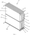
FIG. 1 is a perspective view of a thermal management system according to one embodiment. -
FIG. 2A is a front view of the thermal management system ofFIG. 1 . -
FIG. 2B is a side view of the thermal management system ofFIG. 1 . -
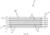
FIG. 2C is a top view of the thermal management system ofFIG. 1 . -
FIG. 3 A is a perspective view of a pouch cell of the thermal management system ofFIG. 1 . -
FIG. 3B is a side view of the pouch cell ofFIG. 3A . -
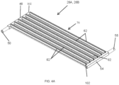
FIG. 4A is a perspective view of a framework of the thermal management system ofFIG. 1 , the framework including an inlet manifold, an outlet manifold, and a plurality of intermediate frame members extending therebetween. -
FIG. 4B is a top view of the framework ofFIG. 4A -
FIG. 4C is a cross-sectional view of the framework ofFIG. 4A -
FIG. 5 is a perspective view of one of the intermediate frame members ofFIG. 4A . -
FIG. 6 is a cross-sectional view of the intermediate frame member ofFIG. 5 . -
FIG. 7 is an enlarged perspective view of a portion of the framework ofFIG. 4A , illustrating (with a clear view of the interior of the framework) one of the intermediate frame members in fluid communication with the inlet manifold. -
FIG. 8 is a perspective view of a portion of the inlet manifold ofFIG. 7 . -
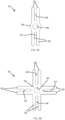
FIG. 9A is a cross-sectional view of another embodiment of the intermediate frame member, the intermediate frame member having four protrusions. -
FIG. 9B is a cross-sectional view of another embodiment of the intermediate frame member, the intermediate frame member having eight protrusions. -
FIGS. 10A-10D are cross-sectional views of the intermediate frame member ofFIG. 9A , illustrating different shaped microchannels. -
FIG. 11 is a perspective view of two of the thermal management systems ofFIG. 1 , stacked together. -
FIG. 12A is a perspective view of the stacked thermal management systems ofFIG. 11 , without the plurality of pouch cells. -
FIG. 12B is a side view of the stacked thermal management systems ofFIG. 12A . -
FIG. 13 is an enlarged perspective view of a portion of the stacked thermal management systems ofFIG. 12A . - Before any constructions of the invention are explained in detail, it is to be understood that the invention is not limited in its application to the details of construction and the arrangement of components set forth in the following description or illustrated in the following drawings. The invention is capable of other constructions and of being practiced or of being carried out in various ways. Also, it is to be understood that the phraseology and terminology used herein is for the purpose of description and should not be regarded as limited.
- The term "thermal management system" used herein refers to any system that is arranged to remove heat from one or more heat sources and to move the heat to a separate location. The term "spreader" used herein refers for example to a plate, sheet, disk, enclosure, chamber, or other structure that receives heat and spreads or otherwise moves the heat from one location to another (e.g., linearly or generally within a plane defined by the spreader). The term "k-Core" used herein refers to Thermacore's k-Core technology (k-Core® material, available from Thermacore, Inc. of Lancaster, PA 17601), which uses encapsulated graphite to move heat (e.g., in avionic applications). One example of k-Core technology material is encapsulated annealed pyrolytic graphite (APG) which creates high-conductivity thermal spreading (e.g., up to three times the conductivity of solid copper with lower mass than aluminum). The term "encapsulated" or "encapsulating material" or "encapsulant" used herein refers, for example, to material (e.g., an aluminum foil, copper alloy, ceramic, composite, or other material) that forms an enclosure or covering or in some instances a chamber and that encapsulates or otherwise encloses and contains material therein, such as k-Core material.
- In one exemplary embodiment, as shown in
FIG. 1 , athermal management system 10 may be used in any application where multiple heat dissipating devices, such as battery packs or other electrical components, including a closely-packed or stacked heat source, require temperature control within a specific temperature range or an isothermal temperature profile throughout the device. The present embodiment can be applied in thermal management of electric vehicle battery packs using flat or generallyflat pouch cells 14 stacked in multiple banks of cells that are installed into an overall battery pack chassis. Each bank ofpouch cells 14 is directly coupled to or otherwise is in communication with one or more of thethermal management systems 10 described herein. The term "pouch cell" used herein refers to a heat source, and in the illustrated embodiment, to a heat source having a structure that acts as a fuel cell or battery cell of a battery pack. Thepouch cell 14 defines an enclosure or chamber therein for generation of energy.FIGS. 3A and 3B illustrate asingle pouch cell 14. - Other cell formats, including, but not limited to cylindrical cells, are also envisioned. Cylindrical cells represent a common type of battery format (e.g., for an AA battery) typically for consumer use. The interior of a typical cylindrical battery includes three concentric layers of film/foil (copper, polymer isolation layer and aluminum foil) that are rolled up inside the battery cylinder and that define the current and voltage. One foil (e.g., aluminum) has a carbon coating that stores the charge. An electrolyte fills the voids between the layers. In some embodiments, rather than rolling up the adjacent foil and polymer layers into a cylinder, multiple separate sheets of foil and polymer are stacked on top of one-another. The foil layers may be vacuum sealed within a polymer film container (typically used in the food industry) that forms a flat rectangular pack. The laminated layers forming the positive and negative terminals are exposed. The rectangular shape increases packing density into the pack chassis.
- In some embodiments, the
thermal management system 10 described herein includes three main components (seeFIGS. 1 ,2A-2C , and7 ): - 1. a
thermal conduction device 22; - 2. a
thermal regulation system - 3. a
thermal extraction interface 30. - With reference to
FIGS. 1 and2A , thethermal management system 10 includes a firstthermal regulation system 26A disposed on one side of the pouch cells 14 (e.g., above the pouch cells 14) and a secondthermal regulation system 26B disposed on an opposite side of the pouch cells 14 (e.g., below the pouch cells 14).Thermal conduction devices 22 extend from each of thethermal regulation systems pouch cells 14, including in betweenadjacent pouch cells 14. - The
thermal conduction device 22 may be any heat transfer device (e.g., a heat spreader) that receives heat from one or more of the pouch cells 14 (or other heat sources) and transfers the heat away from thepouch cell 14 and to one of thethermal regulation systems thermal conduction device 22 includes a flat or generally flat conduction plate 34 (e.g., a flexible sheet) made of graphite (e.g., encapsulated graphite). Theconduction device 22 contacts a surface 38 (FIG. 3A ) of thepouch cell 14 or is otherwise closely positioned or spaced relative to thesurface 38 of thepouch cell 14 for thermal communication with thepouch cell 14. In some embodiments, thethermal conduction device 22 may be positioned proximate thesurface 38 of thepouch cell 14 such that there is a gap between thethermal conduction device 22 and thepouch cell 14. In this configuration, thethermal conduction device 22 still receives heat from thepouch cell 14 even though thethermal conduction device 22 is spaced from thepouch cell 14. - The
thermal conduction plate 34 has relatively high thermal conductivity to produce uniform heat distribution across the surfaces of thepouch cell 14, smoothing out hot spots and creating a more isothermal temperature profile across thesurface 38 of thepouch cell 14. In some embodiments, and as described further herein, an edge of theplate 34 extends past thepouch cell surface 38 and thermally interfaces with a secondary heat extraction system (e.g., one of thethermal regulation systems pouch cell 14 within a required operating temperature range. High thermal conductivity materials other than graphite, including but not limited to aluminum and copper, may be used in alternative embodiments of thethermal conduction device 22. - One feature of the illustrated
thermal conduction device 22 is the use of an encapsulated graphite material for heat transfer. For example, a graphite material core with very high in-plane thermal conductivity in comparison to copper and aluminum, may be protected (e.g., encapsulated) within a protective skin (metal foil, polymer, composite sheet, carbon fiber etc.) to provide good thermal transfer capability. The very high in-plane thermal conductivity of the graphite core minimizes the thermal gradient between the high temperature regions of thepouch cell 14 and the interface with thethermal regulation system pouch cell surface 38 that is close to or approaching isothermal conditions. - With continued reference to
FIGS. 1 and2A , the use of theconduction plate 34 as a graphite spreader may provide further increased flexibility in comparison to solid metal plates. This flexibility accommodates expansion and contraction of thepouch cell 14 caused by expansion and contraction of the electrolyte solution contained within thepouch cell 14 in response to changes in temperature. To benefit from the increased flexibility of the graphite-basedconduction plate 34, and as illustrated inFIG. 1 , a configuration of thethermal conduction device 22 may incorporateseparate conduction plates 34 that are connected independently to the upper and lowerthermal regulation systems thermal regulation systems thermal conduction devices 22, increased flexibility is achieved. - A further embodiment of the
thermal conduction device 22 uses graphene sheets or films as an alternative to graphite. As graphene has excellent barrier properties, there is no need to encapsulate the graphene, providing an improvement in thermal performance versus that of an encapsulated graphite device. In addition, the 2D-like configuration or flat nature of the graphene sheets has a very small thickness and gives a very high level of flexibility. - In some embodiments the grains of the graphene or graphite flakes are all aligned along a common direction in a plane of the thermal conducting device, such that heat is directed in the common direction.
- It should be noted that the surface of the graphene may be functionalized, potentially by the addition of a copper flash or polymerization. Functionalization achieves benefits such as improved through-plane thermal conductivity and increased adhesion of the individual graphene layers. Although true graphene should be one atom thick (2D), commercially available materials can be manufactured from using flakes with up to 20 layers. The surface of the flakes is functionalized by, for example, polymerization which helps protect the graphene and helps the flakes adhere to one another during consolidation. Copper flash does the same but has a higher thermal conductivity and is more difficult to consolidate into bulk material.
- In a further embodiment of the
thermal management system 10, thepouch cell 14 directly incorporates thethermal conduction device 22 within thepouch cell 14, eliminating or reducing thermal resistance between thethermal conduction device 22 and thepouch cell surface 38 in the thermal path. As such, in this configuration, the heat source orpouch cell 14 is directly coupled to thethermal regulation system pouch cell 14 can be made isothermal (i.e., a 3D isothermal temperature profile). In a case where graphite or graphene based thermal conduction materials are used, the material may replace the existing graphitic layer and perform both the electrical and thermal functions within thepouch cell 14. - With reference to the exemplary embodiment of
FIGS. 4A-4C , each of thethermal regulation systems thermal conduction devices 22. In the illustrated embodiment, as shown inFIG. 4A-4C , eachthermal regulation systems first frame member 46 having aninlet 50 to receive a working fluid A (e.g., coolant / refrigerant / two-phase flow, as illustrated inFIG. 4C ). Each of thethermal regulation systems second frame member 54 that is spaced from thefirst frame member 46. In the illustrated embodiment, thesecond frame member 54 extends parallel to thefirst frame member 46. Thesecond frame member 54 includes anoutlet 58 for the working fluid A to exit thethermal regulation system FIG. 4C , the working fluid A may enter theinlet 50 in one direction, and exit theoutlet 58 in the same direction. Thethermal regulation system intermediate frame members 62 that extend between the first andsecond frame members FIGS. 4A-4C , theintermediate frame members 62 extend perpendicularly relative to the first andsecond frame members thermal conduction devices 22 are coupled to the intermediate frame members 62 (e.g., seeFIG. 13 ). More specifically, thethermal conduction devices 22 are releasably coupled to theintermediate frame members 62. - The
thermal regulation systems thermal conduction devices 22, and thermally regulate the operating temperature of the overallthermal management system 10. In the illustrated embodiment, and as described above, thethermal management system 10 includes an upperthermal regulation system 26A and a lowerthermal regulation system 26B. In other embodiments, thethermal management system 10 may include only one thermal regulation system 26, or more than two thermal regulation systems. The upper and lowerthermal regulation systems FIGS. 1 ,2A-2C , are configured to form the structure of arigid chassis 70, or more particularly, a low mass rigid chassis, to which thethermal conduction devices 22 and/orpouch cells 14 are coupled. Theintermediate frame members 62 of thechassis 70 incorporate fluid flow channels 66 (e.g., microchannels) that enable the working fluid A to pass through thechassis 70. By controlling the flowrate and inlet temperature of the working fluid A, heat extraction from thethermal conduction devices 22 and the temperatures of thethermal conduction devices 22 andpouch cells 14 are controlled. -
FIGS. 4A-4C illustrate one of the upper or lowerthermal regulation systems thermal regulation system first frame member 46 and the second frame member 54) that form the outer framework of thechassis 70. The first andsecond frame members intermediate frame members 62. Theintermediate frame members 62 are a series of parallel structural elements that act as struts or cross-struts. As noted above, theintermediate frame members 62 extend, in some embodiments, perpendicularly between thefirst frame member 46 and the second frame member 54 (seeFIGS. 4A-4C ). - With continued reference to
FIGS. 4A-4C , theouter framework elements 46, 54 (i.e., the first and second frame members) are hollow, forming large inlet andoutlet conduits conduit 74 of thefirst frame member 46 of theouter framework elements FIG. 8 ) to theintermediate frame members 62. Theintermediate frame members 62 are also hollow, but in contrast to thelarge conduit 74 of thefirst frame member 46, each of theintermediate frame members 62 includes at least onemicrochannel 66. More specifically, themicrochannels 66 provide relatively high thermal efficiency flow passages that enhance the collection of heat from the parallelthermal conduction devices 22 and transfer the collected heat into the working fluid A flowing through themicrochannels 66. Theconduit 78 of thesecond frame member 54 of theouter framework elements microchannels 66 of theintermediate frame members 62 through outlet ports 84 (FIG. 4C ) of thesecond frame member 54. - Each of the
intermediate frame members 62 includes one of the microchannels 66 (FIG. 5 ) to transfer working fluid A from thefirst frame member 46 to thesecond frame member 54. In other embodiments, theintermediate frame members 62 may be formed with relatively larger channels. Theintermediate frame members 62 thus are configured to conduct the working fluid A along the heated ends of thethermal conduction devices 22 coupled to theintermediate frame members 62 so that heat generated by thethermal conduction devices 22 is absorbed by the working fluid A as the working fluid flows through thesecond frame member 54. The heat absorbed from thethermal conduction devices 22 by the working fluid A is then transferred out of each of thethermal regulation systems outlet 58 ofsecond frame member 54. - With reference to
FIGS. 4C ,7, and 8 , in the illustrated embodiment, theintermediate frame members 62 are joined to the first andsecond frame members FIG. 4C ) in a parallel flow configuration (other configurations may be used) that balances the pressure drop and/or the flow rate through each microchannel 66. This fluid flow passage network may facilitate a uniform heat transfer coefficient within eachparallel microchannel 66. In particular,FIGS. 7 and 8 illustrate theinlet conduit 74, theinlet ports 82, and themicrochannels 66 in fluid communication. The illustratedoutlet conduit 78 andoutlet ports 84 are similarly configured to interact with themicrochannels 66 to move the working fluid A. In the illustrated embodiment, thethermal conduction devices 22 extend away from the framework orchassis 70 along a direction that is perpendicular to a direction of movement of working fluid within the framework of thethermal regulation systems - With reference to
FIGS. 5 and6 , thethermal extraction interface 30 corresponds to the connections between thethermal conduction devices 22 and thethermal regulation systems FIGS. 5 and δ, the profile of each of the plurality ofintermediate frame members 62 includes two main features. The first feature is a circular (or other shape)tube portion 86 within which thecircular microchannel passage 66 runs along the longitudinal axis of theintermediate frame member 62. As shown, Thetube portions 86 are in fluid communication with the inlet andoutlet ports conduits circular tube portions 86. Theprotrusions 90 form a slot 94 (e.g., groove, crease, etc.) therebetween that extends along a longitudinal axis of theintermediate frame member 62. - A portion of each of the
thermal conduction devices 22 is received and held in theslot 94 formed by each pair of spaced-apartprotrusions 90 to form thethermal extraction interface 30 between thethermal conduction device 22 and thetube 86. In particular, heat generated by thethermal conduction devices 22 and received by the pair of spaced-apartparallel protrusions 90 is conducted through thecircular tube portion 86 where the heat is then absorbed by the working fluid A flowing through themicrochannel 66. The wall thicknesses of theparallel protrusions 90 and themicrochannel tube 86 may be varied to optimize heat transfer and minimize the mass of thethermal conduction devices 22. For example, the height and width of theslot 94 may be varied to accommodate various configurations and types of thethermal conduction devices 22 to optimize heat transfer between the thermal conduction devices and the working fluid A flowing through the microchannels of theintermediate frame members 62. An interface material such as solder or epoxy or any other suitable alternative filler material may be used to minimize thermal resistance and maximize thermal conduction across the joint between thethermal conduction devices 22 and the associatedintermediate frame members 62. - With reference to
FIG. 5 , in the illustrated embodiment theintermediate frame members 62 each have a constant cross-sectional profile along the length of its entire length to enable manufacture by extrusion. Alternatively, the cross-sectional profile along the length of theintermediate frame members 62 may be varied by using additional or alternative manufacturing processes. - In some embodiments, a mechanical device may be used to hold the
thermal conduction device 22 in position on theintermediate frame member 62. For example, a wedge and/ or a plate may be used to clamp or otherwise secure athermal conduction device 22 to an intermediate frame member. In some embodiments, theintermediate frame member 62 may only include oneprotrusion 90 instead of a pair of spaced-apart protrusions, and a flat plate may be used to clamp thethermal conduction device 22 to theprotrusion 90 . The protrusion and separate flat plate thus act as a capture feature. The terms "capture feature" or "capture features" refer to any structural features or structures that are used to "capture" (i.e., receive, retain, hold, secure, encompass, etc.) another component, such as thethermal conduction device 22 or one of the first, second, orintermediate frame members - As shown in the embodiment of
FIGS. 7-8 , the first and/orsecond frame member intermediate frame member 62. In the illustrated embodiment, each of the first andsecond frame members FIGS. 7 and 8 ). Therecesses 98 of the first andsecond frame members intermediate frame members 62 relative to the first andsecond frame members microchannels 66 with the inlet andoutlet ports second frame members 46, 54 (FIG. 8 ). In other embodiments, the capture features may be protrusions, fingers, or any other surfaces or structures that are sized and shaped to securely hold one component in position with respect to another component. - In some embodiments, the interfaces between the
intermediate frame members 62 and the first andsecond frame members first frame member 46 opposite theinlet 50 and/or the end of thesecond frame member 54 opposite theoutlet 58 are sealed using a cap 102 (FIG. 4A ). - With reference to
FIGS. 9A-10D , the cross-sectional profile of each of the illustratedmicrochannels 66 may be designed to minimize mass (i.e., weight) of the framework, and/or to minimize thermal resistance and improve thermal conduction. For example, thesingle microchannel 66 may be replaced with a multi-channel configuration (FIGS. 10C-10D ) to increase heat transfer. The channel shape and size also may varied. For example, the cross-sectional profile ofmicrochannel 66 may be shaped as a square, triangle or any other desired shape to provide a capillary action. Examples of such different cross-sectional profiles formicrochannels 66 are shown inFIGS. 10A-10D , including multi-channel configurations. In addition, more than onethermal conduction device 22 may be thermally associated with eachintermediate frame member 62. For example,intermediate frame members 62 provided with more than one capture feature (e.g., two or more pairs of spaced-apart protrusions 90) to hold more than onethermal conduction device 22 are shown inFIGS. 9A and 9B . - In some embodiments,
intermediate frame members 62 with two capture features (e.g., two pairs of spaced-apart parallel protrusions 90) may be used, for example, to thermally manage two battery cells as shown, for example, inFIGS. 11-12B . In the illustrated embodiment, the mass of the entirethermal transfer device 10 is reduced in that two sets of battery cells are thermally managed by threethermal regulation systems thermal regulations systems intermediate frame members 62 of thethermal management system 26B are configured as having the cross-section profile as shown inFIG. 9A (theintermediate frame members 62 including two pairs of spaced-apart parallel protrusions 90). In other embodiments, thethermal management system 10 may include multiple sets of battery cells such that theintermediate frame members 62 of thethermal management system 26B are configured as having the cross-section profiles as shown inFIG. 9B (theintermediate frame members 62 including four pairs of spaced-apart parallel protrusions 90A). A close-up view of the assembled components of thethermal management system 10 ofFIG. 12A , in particular thethermal regulation system 26B, is shown inFIG. 13 . The overall assembly with thepouch cells 14 in position is also shown inFIG. 11 . - In some embodiments, the
chassis 70 may be formed as a light-weight chassis framework, manufactured from brazed aluminum extrusion profiles (or material other than aluminum) to form parallel flow liquid cold plates or frame members including, for example, theintermediate frame members 62. Each parallelintermediate frame member 62 andflow channel 66 connects to a k-Core foil encapsulated spreader (e.g., conduction device 22) that is installed between twoadjacent pouch cells 14. During use, the pouch cells 14 (or other heat sources) generate heat. That heat is transferred to the associated or adjacent thermal conduction device(s) 22 (e.g., to the k-Core plates 34). Thethermal conduction devices 22 extend parallel to one another, and extend into spaces or gaps between the pouch cells 14 (e.g., like fingers). Thus, thethermal conduction devices 22 pick up the heat from thepouch cells 14 and move the heat away from thepouch cells 14 toward thethermal regulation system FIG. 1 , and as described above, a first upperthermal regulation system 26A and a second lowerthermal regulation system 26B are provided. Thethermal conduction devices 22 extend from both the firstthermal regulation system 26A and the secondthermal regulation system 26B (e.g., toward each other). Once the heat reaches the ends or edges of the thermal conduction devices 22 (which are captured or otherwise held by theprotrusions 90 of the intermediate frame members 62), the heat moves into themicrochannels 66 in theintermediate frame members 62. From there the heat is picked up by the working fluid A passing through themicrochannels 66, and is moved to thesecond frame member 54 and then out of thethermal management system 10. - The
thermal management systems 10 described herein may be used in electric vehicle (EV) thermal management. In particular, in some embodiments they are directed for use with Formula-E battery packs and other high performance EV applications, although they could be used on vehicles other than electric vehicles, or could be used in systems other than vehicles (e.g., in stationary systems that have heat sources, such as electronics) to remove heat. In some embodiments, thethermal management systems 10 described herein may be used in high performance electric vehicle battery pack applications and low volume and niche EV automotive applications (e.g. busses, excavators, tractors, trucks, etc.). - In some embodiments, the
thermal management systems 10 include (1) use of K-Core as a thermal spreader to regulate and even out pouch cell temperature, (2) a K-Core thermal transport to a liquid cooling system and integration with the cooling system, (3) a method or arrangement of interconnections between K-Core material and a cooling system, and/or (4) a design of a liquid cooling system to be astructural chassis framework 70. - Although the invention has been described in detail with reference to certain preferred constructions, variations and modifications exist within the scope of one or more independent aspects of the invention as described. Various features and advantages of the invention are set forth in the following claims.
Claims (15)
- A device (10) for removal of heat from a plurality of heat sources, the device comprising:a first manifold (46) configured to receive a working fluid;a plurality of first elongated intermediate frame members (62) each in thermal communication with at least one of the plurality of heat sources, each first elongated intermediate frame member (62) including a channel (66) in fluid communication with the first manifold (46) and configured to receive the working fluid from the first manifold (46), wherein each first elongated intermediate frame member (62) includes a slot (94) defined by two spaced apart protrusions (90) extending outwardly from the first elongated intermediate frame member (62) and parallel to one another along a longitudinal axis of the first elongated intermediate frame member (62);a second manifold (54) spaced from the first manifold (46) and in fluid communication with the plurality of first elongated intermediate frame members (62) to receive the working fluid from each channel (66) in the plurality of first elongated intermediate frame members (62), wherein the second manifold (54) is configured to transfer the working fluid away from the plurality of heat sources, wherein the working fluid flows through the first manifold (46), anda plurality of first thermal conducting devices (22), wherein each of the first thermal conducting devices (22) is formed as a plate with a first end extending along the longitudinal axis, and wherein the first end is disposed within one of the slots (94) of the first elongated intermediate frame members (62) to position the first thermal conducting device (22) adjacent at least one of the plurality of heat sources (14), and wherein a second end of the first thermal conducting device (22) opposite the first end is disposed outside of the slot (94).
- The device (10) of claim 1, further comprising a plurality of recesses (98) defined by at least one of the first manifold (46) and the second manifold (54), each recess (98) having a shape that corresponds to a cross-sectional shape of an end of each of the plurality of first elongated intermediate frame members (62), wherein each recess (98) is configured to receive an end of one of the plurality of first elongated intermediate frame members (62).
- The device (10) of claim 1 or 2, wherein each of the plurality of first elongated intermediate frame members (62) extends parallel to another one of the plurality of first elongated intermediate frame members (62).
- The device (10) of claim 2 or claim 3, wherein the plurality of recesses (98) are positioned to align each channel (66) with a first internal channel (74) of the first manifold (46) and a second internal channel (78) of the second manifold (54).
- The device (10) of any of the preceding claims, wherein the plurality of first elongated intermediate frame members (62) are welded to both the first manifold (46) and the second manifold (54).
- The device (10) of any of the preceding claims, wherein a cross-sectional shape of the channel (66) includes at least one from the group of shapes consisting of round, square, and triangular.
- The device (10) of any of the preceding claims, wherein the channel (66) is one of a plurality of channels (66) in each first elongated intermediate frame member (62).
- The device (10) of any of the preceding claims, wherein each first thermal conducting device (22) is configured to receive heat from one of the plurality of heat sources.
- The device (10) of any one of claims 1 to 8, wherein each first elongated intermediate frame member (62) includes a tube portion (86), and wherein the channel (66) is located within the tube portion (86).
- The device (10) of any one of claims 1 to 8, wherein each first elongated intermediate frame member (62) includes a tube portion (86) and eight protrusions (90) extending outwardly from the tube portion (86) and parallel to one another along a longitudinal axis of the first elongated intermediate frame member (62), wherein two of the eight protrusions (90) define the slot (94), and the remaining six protrusions are spaced apart to from pairs that define three other separate slots (94), and whereon the slots (94) are spaced apart 90° from one another around each of the first elongated frame members (62).
- The device (10) of any of the preceding claims, wherein the first thermal conducting devices (22) are plates of encapsulated graphite.
- The device (10) of any of the preceding claims, wherein the the first manifold (46), the plurality of first elongated intermediate frame members (62), and the second manifold (54) are located in a first plane, and wherein each of the first thermal conducting devices (22) extends away from the first plane along a second plane that is perpendicular to the first plane.
- The device (10) of any of the preceding claims further comprising:
a third manifold (46) spaced from each of the first manifold (46) and the second manifold (54);a fourth manifold (54) spaced from each of the first manifold (46), the second manifold (54), and the third manifold (46); anda plurality of second elongated intermediate frame members (62) extending between the third manifold (46) and the fourth manifold (54), where each second elongated intermediate frame member (62) is in thermal communication with at least one of the plurality of heat sources, wherein each elongated second intermediate frame member (62) includes a slot (94) extending along a longitudinal axis of the second elongated intermediate frame member (62) and defined by two spaced apart protrusions (90) extending outwardly from the second elongated intermediate frame member (62) and parallel to one another along the longitudinal axis of the second elongated intermediate frame member (62); anda plurality of second thermal conducting devices (22), wherein each of the second thermal conducting devices (22) has a first end extending along the longitudinal axis of the second elongated intermediate frame member (62), and wherein the first end of the second thermal conducting device (22) is disposed within one of the slots (94) of the second elongated intermediate frame members (62) and extends toward one of the first thermal conducting devices (22). - The device (10) of any of the claims 1 to 12, wherein the slot (94) on each first elongated intermediate frame member (62) is a first slot (94) and further comprises a second slot (94) on each first elongated intermediate frame member (62), wherein the second slot (94) is defined by two protrusion (90) extending outwardly from the first elongated intermediate frame member (62) and parallel to one another the longitudinal axis of the first elongated intermediate frame member (62), wherein the second slot (94) is positioned opposite the first slot to receive one of a plurality of second thermal conducting devices (22).
- The device (10) of any of the claims 1 to 12, wherein the slot (94) extends along the longitudinal axis of the elongated intermediate frame member (62), wherein the slot (94) has a closed end that extends along the longitudinal axis and is proximal to a longitudinal boundary of the channel (66) and an opposite open end that extends along the longitudinal axis and is distal to the longitudinal boundary of the channel (66).
Applications Claiming Priority (2)
| Application Number | Priority Date | Filing Date | Title |
|---|---|---|---|
| US201762593706P | 2017-12-01 | 2017-12-01 | |
| PCT/US2018/063340 WO2019108950A1 (en) | 2017-12-01 | 2018-11-30 | Thermal management system |
Publications (3)
| Publication Number | Publication Date |
|---|---|
| EP3717301A1 EP3717301A1 (en) | 2020-10-07 |
| EP3717301A4 EP3717301A4 (en) | 2021-08-18 |
| EP3717301B1 true EP3717301B1 (en) | 2024-10-23 |
Family
ID=66665809
Family Applications (1)
| Application Number | Title | Priority Date | Filing Date |
|---|---|---|---|
| EP18882547.5A Active EP3717301B1 (en) | 2017-12-01 | 2018-11-30 | Device for removal of heat from a plurality of heat sources |
Country Status (4)
| Country | Link |
|---|---|
| US (1) | US11881574B2 (en) |
| EP (1) | EP3717301B1 (en) |
| CN (1) | CN111712402A (en) |
| WO (1) | WO2019108950A1 (en) |
Families Citing this family (2)
| Publication number | Priority date | Publication date | Assignee | Title |
|---|---|---|---|---|
| CN111692900B (en) | 2019-09-30 | 2021-08-06 | 浙江三花智能控制股份有限公司 | Heat exchanger and method of making the same |
| US12160011B2 (en) * | 2022-06-14 | 2024-12-03 | Beta Air Llc | Battery pack for a carbon fiber pouch cell casing configured to cool battery cells |
Family Cites Families (40)
| Publication number | Priority date | Publication date | Assignee | Title |
|---|---|---|---|---|
| US5230966A (en) | 1991-09-26 | 1993-07-27 | Ballard Power Systems Inc. | Coolant flow field plate for electrochemical fuel cells |
| US5863671A (en) | 1994-10-12 | 1999-01-26 | H Power Corporation | Plastic platelet fuel cells employing integrated fluid management |
| US6790554B2 (en) | 1998-10-08 | 2004-09-14 | Imperial Chemical Industries Plc | Fuel cells and fuel cell plates |
| US6274262B1 (en) | 1999-08-24 | 2001-08-14 | Plug Power Inc. | Fuel cell bi-cooler flow plate |
| EP1148547B8 (en) * | 2000-04-19 | 2016-01-06 | Denso Corporation | Coolant cooled type semiconductor device |
| EP1793438B1 (en) | 2000-08-17 | 2013-07-10 | Panasonic Corporation | Polymer electrolyte fuel cell |
| US6817097B2 (en) | 2002-03-25 | 2004-11-16 | Thermal Corp. | Flat plate fuel cell cooler |
| US6903929B2 (en) * | 2003-03-31 | 2005-06-07 | Intel Corporation | Two-phase cooling utilizing microchannel heat exchangers and channeled heat sink |
| DE102004057526B4 (en) * | 2003-12-03 | 2020-08-20 | Denso Corporation | Stack cooler |
| US20070116996A1 (en) | 2005-11-22 | 2007-05-24 | Teledyne Technologies Incorporated | Regenerative fuel cell/electrolyzer stack |
| US20080076005A1 (en) | 2006-09-22 | 2008-03-27 | Michel Bitton | Fuel cell fluid distribution system |
| JP2009054297A (en) * | 2007-08-23 | 2009-03-12 | Toshiba Corp | Battery pack |
| US8081473B2 (en) * | 2008-08-04 | 2011-12-20 | International Business Machines Corporation | Apparatus and method of direct water cooling several parallel circuit cards each containing several chip packages |
| US7883793B2 (en) | 2008-06-30 | 2011-02-08 | Lg Chem, Ltd. | Battery module having battery cell assemblies with alignment-coupling features |
| US8383280B2 (en) | 2008-08-12 | 2013-02-26 | Amir Niroumand | Fuel cell separator plate with integrated heat exchanger |
| GB2481771B (en) * | 2009-04-29 | 2013-08-28 | Hewlett Packard Development Co | Printed circuit board cooling assembly |
| US8403030B2 (en) * | 2009-04-30 | 2013-03-26 | Lg Chem, Ltd. | Cooling manifold |
| US8852778B2 (en) * | 2009-04-30 | 2014-10-07 | Lg Chem, Ltd. | Battery systems, battery modules, and method for cooling a battery module |
| KR101130043B1 (en) | 2009-07-27 | 2012-03-28 | 주식회사 엘지화학 | Battery Module of Improved Cooling Efficiency |
| US8399118B2 (en) | 2009-07-29 | 2013-03-19 | Lg Chem, Ltd. | Battery module and method for cooling the battery module |
| US8027162B2 (en) * | 2009-09-24 | 2011-09-27 | International Business Machines Corporation | Liquid-cooled electronics apparatus and methods of fabrication |
| US20110136030A1 (en) | 2009-12-03 | 2011-06-09 | Enerfuel, Inc. | High temperature pem fuel cell with thermal management system |
| WO2011088997A1 (en) | 2010-01-20 | 2011-07-28 | Fraunhofer-Gesellschaft zur Förderung der angewandten Forschung e.V. | Battery cell array the temperature of which can be controlled |
| CN203398243U (en) * | 2010-05-21 | 2014-01-15 | 格拉弗技术国际控股有限公司 | Thermal management component with opposite main surfaces for battery unit |
| US8343650B2 (en) | 2010-08-11 | 2013-01-01 | GM Global Technology Operations LLC | Modular plate carrier concept for mounting and embedded cooling of pouch cell battery assemblies |
| US9306224B2 (en) * | 2010-09-02 | 2016-04-05 | Akasol Engineering Gmbh | Cooling module and method for producing a cooling module |
| JP5777734B2 (en) | 2011-02-22 | 2015-09-09 | エルジー ケム. エルティーディ. | Cooling member with improved cooling efficiency and battery module using the same |
| US8771382B2 (en) * | 2011-02-25 | 2014-07-08 | GM Global Technology Operations LLC | Heat shrink joining of battery cell components |
| CN103443953B (en) | 2011-03-18 | 2016-04-06 | 达纳加拿大公司 | Battery unit cooler |
| US8587943B2 (en) * | 2011-11-28 | 2013-11-19 | International Business Machines Corporation | Liquid-cooling memory modules with liquid flow pipes between memory module sockets |
| CN102419623B (en) * | 2011-11-30 | 2014-03-26 | 华为技术有限公司 | Memory liquid-cooling heat dissipation method and device as well as system |
| US8734975B2 (en) | 2011-12-21 | 2014-05-27 | Ford Global Technologies, Llc | Modular fluid transport system |
| US9797664B2 (en) * | 2012-02-20 | 2017-10-24 | Neograf Solutions, Llc | Composite heat spreader and battery module incorporating the same |
| US9368843B2 (en) * | 2012-06-04 | 2016-06-14 | Graftech International Holdings, Inc. | Battery pack assembly |
| US9370122B2 (en) * | 2013-01-10 | 2016-06-14 | International Business Machines Corporation | Cooling apparatus with a resilient heat conducting member |
| DE102013201989B4 (en) | 2013-02-07 | 2025-12-24 | Eberspächer Climate Control Systems GmbH | Vehicle heating system |
| DE102013209980A1 (en) * | 2013-05-28 | 2014-12-04 | Behr Gmbh & Co. Kg | Heat exchanger |
| US9496588B2 (en) | 2013-07-30 | 2016-11-15 | Johnson Controls Technology Company | Battery module with cooling features |
| US10103390B2 (en) | 2015-04-20 | 2018-10-16 | Energyor Technologies Inc | Method for producing kiss cut fluid flow field plates |
| CN105895991A (en) * | 2016-05-10 | 2016-08-24 | 济南陆枋志合信息技术有限公司 | Lithium battery power pack cooling system |
-
2018
- 2018-11-30 EP EP18882547.5A patent/EP3717301B1/en active Active
- 2018-11-30 US US16/768,792 patent/US11881574B2/en active Active
- 2018-11-30 CN CN201880088327.5A patent/CN111712402A/en active Pending
- 2018-11-30 WO PCT/US2018/063340 patent/WO2019108950A1/en not_active Ceased
Also Published As
| Publication number | Publication date |
|---|---|
| CN111712402A (en) | 2020-09-25 |
| US11881574B2 (en) | 2024-01-23 |
| US20210175563A1 (en) | 2021-06-10 |
| EP3717301A1 (en) | 2020-10-07 |
| WO2019108950A1 (en) | 2019-06-06 |
| EP3717301A4 (en) | 2021-08-18 |
Similar Documents
| Publication | Publication Date | Title |
|---|---|---|
| CN104051813B (en) | The battery module of liquid cooling | |
| US9761919B2 (en) | Energy storage system with heat pipe thermal management | |
| US12261276B2 (en) | Cold plate blade for battery modules | |
| US8435668B2 (en) | Prismatic battery cell with integrated cooling passages and assembly frame | |
| CN203398244U (en) | Thermal management component with opposite main surfaces for battery unit | |
| EP2962355B1 (en) | Heat transfer device for batteries | |
| CN111403853B (en) | Power battery thermal management system based on joint liquid cooling heat dissipation of utmost point ear and module bottom | |
| CN103262334B (en) | Cooling module and cooling module manufacturing method | |
| CN103443953A (en) | Battery cell cooler | |
| CN101828299A (en) | Device for storing electrical energy | |
| WO2020160028A1 (en) | Film heat exchanger coupling system and method | |
| CN219610564U (en) | Battery pack | |
| US11881574B2 (en) | Thermal management system | |
| Ji et al. | Thermal performance optimization of columnar lithium-ion batteries using a semi-immersion liquid cooling system | |
| CN119742493A (en) | Cylindrical battery cell packaging and cooling configuration | |
| US20160268654A1 (en) | Cost-efficient device for controlling the temperature of a motor vehicle battery module, and manufacturing method | |
| WO2019001467A1 (en) | Lithium ion pouch cell | |
| CN108807730B (en) | Layered electric vehicle battery pack | |
| CN115764052A (en) | Battery module with cladding type flat plate heat pipe structure and battery pack | |
| CN111555000A (en) | Heat dissipation battery module and battery package | |
| CN110556604A (en) | Lithium ion soft package battery | |
| CN121355462B (en) | Battery module | |
| CN115036615B (en) | Heat sink and battery thermal management methods | |
| CN222029152U (en) | Heat exchange assembly and battery pack | |
| CN105932186A (en) | a battery box |
Legal Events
| Date | Code | Title | Description |
|---|---|---|---|
| STAA | Information on the status of an ep patent application or granted ep patent |
Free format text: STATUS: THE INTERNATIONAL PUBLICATION HAS BEEN MADE |
|
| PUAI | Public reference made under article 153(3) epc to a published international application that has entered the european phase |
Free format text: ORIGINAL CODE: 0009012 |
|
| STAA | Information on the status of an ep patent application or granted ep patent |
Free format text: STATUS: REQUEST FOR EXAMINATION WAS MADE |
|
| 17P | Request for examination filed |
Effective date: 20200604 |
|
| AK | Designated contracting states |
Kind code of ref document: A1 Designated state(s): AL AT BE BG CH CY CZ DE DK EE ES FI FR GB GR HR HU IE IS IT LI LT LU LV MC MK MT NL NO PL PT RO RS SE SI SK SM TR |
|
| AX | Request for extension of the european patent |
Extension state: BA ME |
|
| DAV | Request for validation of the european patent (deleted) | ||
| DAX | Request for extension of the european patent (deleted) | ||
| REG | Reference to a national code |
Ref legal event code: R079 Free format text: PREVIOUS MAIN CLASS: B60L0058000000 Ref country code: DE Ref legal event code: R079 Ref document number: 602018075840 Country of ref document: DE Free format text: PREVIOUS MAIN CLASS: B60L0058000000 Ipc: F28F0001220000 |
|
| A4 | Supplementary search report drawn up and despatched |
Effective date: 20210721 |
|
| RIC1 | Information provided on ipc code assigned before grant |
Ipc: F28F 1/22 20060101AFI20210715BHEP Ipc: B60L 50/64 20190101ALI20210715BHEP Ipc: B60L 58/26 20190101ALI20210715BHEP Ipc: F28D 1/053 20060101ALI20210715BHEP Ipc: F28F 1/02 20060101ALI20210715BHEP Ipc: F28F 1/16 20060101ALI20210715BHEP Ipc: F28F 1/20 20060101ALI20210715BHEP Ipc: F28F 9/02 20060101ALI20210715BHEP Ipc: F28F 9/18 20060101ALI20210715BHEP Ipc: H01M 10/613 20140101ALI20210715BHEP Ipc: H01M 10/647 20140101ALI20210715BHEP Ipc: H01M 10/6556 20140101ALI20210715BHEP Ipc: F28D 21/00 20060101ALI20210715BHEP Ipc: F28F 9/16 20060101ALI20210715BHEP |
|
| STAA | Information on the status of an ep patent application or granted ep patent |
Free format text: STATUS: EXAMINATION IS IN PROGRESS |
|
| 17Q | First examination report despatched |
Effective date: 20230314 |
|
| GRAP | Despatch of communication of intention to grant a patent |
Free format text: ORIGINAL CODE: EPIDOSNIGR1 |
|
| STAA | Information on the status of an ep patent application or granted ep patent |
Free format text: STATUS: GRANT OF PATENT IS INTENDED |
|
| INTG | Intention to grant announced |
Effective date: 20240522 |
|
| RIN1 | Information on inventor provided before grant (corrected) |
Inventor name: LYNN, KEVIN, V. Inventor name: MCGLEN, RYAN, J. |
|
| GRAS | Grant fee paid |
Free format text: ORIGINAL CODE: EPIDOSNIGR3 |
|
| GRAA | (expected) grant |
Free format text: ORIGINAL CODE: 0009210 |
|
| STAA | Information on the status of an ep patent application or granted ep patent |
Free format text: STATUS: THE PATENT HAS BEEN GRANTED |
|
| AK | Designated contracting states |
Kind code of ref document: B1 Designated state(s): AL AT BE BG CH CY CZ DE DK EE ES FI FR GB GR HR HU IE IS IT LI LT LU LV MC MK MT NL NO PL PT RO RS SE SI SK SM TR |
|
| REG | Reference to a national code |
Ref country code: GB Ref legal event code: FG4D |
|
| REG | Reference to a national code |
Ref country code: CH Ref legal event code: EP |
|
| REG | Reference to a national code |
Ref country code: DE Ref legal event code: R096 Ref document number: 602018075840 Country of ref document: DE |
|
| REG | Reference to a national code |
Ref country code: IE Ref legal event code: FG4D |
|
| REG | Reference to a national code |
Ref country code: LT Ref legal event code: MG9D |
|
| REG | Reference to a national code |
Ref country code: NL Ref legal event code: MP Effective date: 20241023 |
|
| REG | Reference to a national code |
Ref country code: AT Ref legal event code: MK05 Ref document number: 1735170 Country of ref document: AT Kind code of ref document: T Effective date: 20241023 |
|
| PG25 | Lapsed in a contracting state [announced via postgrant information from national office to epo] |
Ref country code: NL Free format text: LAPSE BECAUSE OF FAILURE TO SUBMIT A TRANSLATION OF THE DESCRIPTION OR TO PAY THE FEE WITHIN THE PRESCRIBED TIME-LIMIT Effective date: 20241023 |
|
| PG25 | Lapsed in a contracting state [announced via postgrant information from national office to epo] |
Ref country code: NL Free format text: LAPSE BECAUSE OF FAILURE TO SUBMIT A TRANSLATION OF THE DESCRIPTION OR TO PAY THE FEE WITHIN THE PRESCRIBED TIME-LIMIT Effective date: 20241023 |
|
| PG25 | Lapsed in a contracting state [announced via postgrant information from national office to epo] |
Ref country code: IS Free format text: LAPSE BECAUSE OF FAILURE TO SUBMIT A TRANSLATION OF THE DESCRIPTION OR TO PAY THE FEE WITHIN THE PRESCRIBED TIME-LIMIT Effective date: 20250223 Ref country code: PT Free format text: LAPSE BECAUSE OF FAILURE TO SUBMIT A TRANSLATION OF THE DESCRIPTION OR TO PAY THE FEE WITHIN THE PRESCRIBED TIME-LIMIT Effective date: 20250224 Ref country code: HR Free format text: LAPSE BECAUSE OF FAILURE TO SUBMIT A TRANSLATION OF THE DESCRIPTION OR TO PAY THE FEE WITHIN THE PRESCRIBED TIME-LIMIT Effective date: 20241023 |
|
| PG25 | Lapsed in a contracting state [announced via postgrant information from national office to epo] |
Ref country code: FI Free format text: LAPSE BECAUSE OF FAILURE TO SUBMIT A TRANSLATION OF THE DESCRIPTION OR TO PAY THE FEE WITHIN THE PRESCRIBED TIME-LIMIT Effective date: 20241023 |
|
| PG25 | Lapsed in a contracting state [announced via postgrant information from national office to epo] |
Ref country code: BG Free format text: LAPSE BECAUSE OF FAILURE TO SUBMIT A TRANSLATION OF THE DESCRIPTION OR TO PAY THE FEE WITHIN THE PRESCRIBED TIME-LIMIT Effective date: 20241023 |
|
| PG25 | Lapsed in a contracting state [announced via postgrant information from national office to epo] |
Ref country code: ES Free format text: LAPSE BECAUSE OF FAILURE TO SUBMIT A TRANSLATION OF THE DESCRIPTION OR TO PAY THE FEE WITHIN THE PRESCRIBED TIME-LIMIT Effective date: 20241023 |
|
| PG25 | Lapsed in a contracting state [announced via postgrant information from national office to epo] |
Ref country code: NO Free format text: LAPSE BECAUSE OF FAILURE TO SUBMIT A TRANSLATION OF THE DESCRIPTION OR TO PAY THE FEE WITHIN THE PRESCRIBED TIME-LIMIT Effective date: 20250123 |
|
| PG25 | Lapsed in a contracting state [announced via postgrant information from national office to epo] |
Ref country code: AT Free format text: LAPSE BECAUSE OF FAILURE TO SUBMIT A TRANSLATION OF THE DESCRIPTION OR TO PAY THE FEE WITHIN THE PRESCRIBED TIME-LIMIT Effective date: 20241023 Ref country code: LV Free format text: LAPSE BECAUSE OF FAILURE TO SUBMIT A TRANSLATION OF THE DESCRIPTION OR TO PAY THE FEE WITHIN THE PRESCRIBED TIME-LIMIT Effective date: 20241023 Ref country code: GR Free format text: LAPSE BECAUSE OF FAILURE TO SUBMIT A TRANSLATION OF THE DESCRIPTION OR TO PAY THE FEE WITHIN THE PRESCRIBED TIME-LIMIT Effective date: 20250124 |
|
| PG25 | Lapsed in a contracting state [announced via postgrant information from national office to epo] |
Ref country code: PL Free format text: LAPSE BECAUSE OF FAILURE TO SUBMIT A TRANSLATION OF THE DESCRIPTION OR TO PAY THE FEE WITHIN THE PRESCRIBED TIME-LIMIT Effective date: 20241023 |
|
| PG25 | Lapsed in a contracting state [announced via postgrant information from national office to epo] |
Ref country code: RS Free format text: LAPSE BECAUSE OF FAILURE TO SUBMIT A TRANSLATION OF THE DESCRIPTION OR TO PAY THE FEE WITHIN THE PRESCRIBED TIME-LIMIT Effective date: 20250123 |
|
| REG | Reference to a national code |
Ref country code: CH Ref legal event code: PL |
|
| PG25 | Lapsed in a contracting state [announced via postgrant information from national office to epo] |
Ref country code: SM Free format text: LAPSE BECAUSE OF FAILURE TO SUBMIT A TRANSLATION OF THE DESCRIPTION OR TO PAY THE FEE WITHIN THE PRESCRIBED TIME-LIMIT Effective date: 20241023 |
|
| PG25 | Lapsed in a contracting state [announced via postgrant information from national office to epo] |
Ref country code: MC Free format text: LAPSE BECAUSE OF FAILURE TO SUBMIT A TRANSLATION OF THE DESCRIPTION OR TO PAY THE FEE WITHIN THE PRESCRIBED TIME-LIMIT Effective date: 20241023 |
|
| PG25 | Lapsed in a contracting state [announced via postgrant information from national office to epo] |
Ref country code: DK Free format text: LAPSE BECAUSE OF FAILURE TO SUBMIT A TRANSLATION OF THE DESCRIPTION OR TO PAY THE FEE WITHIN THE PRESCRIBED TIME-LIMIT Effective date: 20241023 |
|
| PG25 | Lapsed in a contracting state [announced via postgrant information from national office to epo] |
Ref country code: LU Free format text: LAPSE BECAUSE OF NON-PAYMENT OF DUE FEES Effective date: 20241130 |
|
| REG | Reference to a national code |
Ref country code: CH Ref legal event code: PL |
|
| PG25 | Lapsed in a contracting state [announced via postgrant information from national office to epo] |
Ref country code: EE Free format text: LAPSE BECAUSE OF FAILURE TO SUBMIT A TRANSLATION OF THE DESCRIPTION OR TO PAY THE FEE WITHIN THE PRESCRIBED TIME-LIMIT Effective date: 20241023 |
|
| PG25 | Lapsed in a contracting state [announced via postgrant information from national office to epo] |
Ref country code: CH Free format text: LAPSE BECAUSE OF NON-PAYMENT OF DUE FEES Effective date: 20241130 |
|
| PG25 | Lapsed in a contracting state [announced via postgrant information from national office to epo] |
Ref country code: RO Free format text: LAPSE BECAUSE OF FAILURE TO SUBMIT A TRANSLATION OF THE DESCRIPTION OR TO PAY THE FEE WITHIN THE PRESCRIBED TIME-LIMIT Effective date: 20241023 |
|
| REG | Reference to a national code |
Ref country code: DE Ref legal event code: R097 Ref document number: 602018075840 Country of ref document: DE |
|
| PG25 | Lapsed in a contracting state [announced via postgrant information from national office to epo] |
Ref country code: SK Free format text: LAPSE BECAUSE OF FAILURE TO SUBMIT A TRANSLATION OF THE DESCRIPTION OR TO PAY THE FEE WITHIN THE PRESCRIBED TIME-LIMIT Effective date: 20241023 |
|
| PG25 | Lapsed in a contracting state [announced via postgrant information from national office to epo] |
Ref country code: CZ Free format text: LAPSE BECAUSE OF FAILURE TO SUBMIT A TRANSLATION OF THE DESCRIPTION OR TO PAY THE FEE WITHIN THE PRESCRIBED TIME-LIMIT Effective date: 20241023 |
|
| PG25 | Lapsed in a contracting state [announced via postgrant information from national office to epo] |
Ref country code: IT Free format text: LAPSE BECAUSE OF FAILURE TO SUBMIT A TRANSLATION OF THE DESCRIPTION OR TO PAY THE FEE WITHIN THE PRESCRIBED TIME-LIMIT Effective date: 20241023 |
|
| REG | Reference to a national code |
Ref country code: BE Ref legal event code: MM Effective date: 20241130 |
|
| PLBE | No opposition filed within time limit |
Free format text: ORIGINAL CODE: 0009261 |
|
| STAA | Information on the status of an ep patent application or granted ep patent |
Free format text: STATUS: NO OPPOSITION FILED WITHIN TIME LIMIT |
|
| PG25 | Lapsed in a contracting state [announced via postgrant information from national office to epo] |
Ref country code: SE Free format text: LAPSE BECAUSE OF FAILURE TO SUBMIT A TRANSLATION OF THE DESCRIPTION OR TO PAY THE FEE WITHIN THE PRESCRIBED TIME-LIMIT Effective date: 20241023 |
|
| GBPC | Gb: european patent ceased through non-payment of renewal fee |
Effective date: 20250123 |
|
| 26N | No opposition filed |
Effective date: 20250724 |
|
| PG25 | Lapsed in a contracting state [announced via postgrant information from national office to epo] |
Ref country code: GB Free format text: LAPSE BECAUSE OF NON-PAYMENT OF DUE FEES Effective date: 20250123 Ref country code: BE Free format text: LAPSE BECAUSE OF NON-PAYMENT OF DUE FEES Effective date: 20241130 |
|
| PG25 | Lapsed in a contracting state [announced via postgrant information from national office to epo] |
Ref country code: FR Free format text: LAPSE BECAUSE OF NON-PAYMENT OF DUE FEES Effective date: 20241223 |
|
| PG25 | Lapsed in a contracting state [announced via postgrant information from national office to epo] |
Ref country code: IE Free format text: LAPSE BECAUSE OF NON-PAYMENT OF DUE FEES Effective date: 20241130 |
|
| PGFP | Annual fee paid to national office [announced via postgrant information from national office to epo] |
Ref country code: DE Payment date: 20251119 Year of fee payment: 8 |
|
| PG25 | Lapsed in a contracting state [announced via postgrant information from national office to epo] |
Ref country code: CY Free format text: LAPSE BECAUSE OF FAILURE TO SUBMIT A TRANSLATION OF THE DESCRIPTION OR TO PAY THE FEE WITHIN THE PRESCRIBED TIME-LIMIT; INVALID AB INITIO Effective date: 20181130 |