EP3717201B1 - Preforms for stretch-blow-moulding containers and continuous blow moulding machine producing the containers - Google Patents
Preforms for stretch-blow-moulding containers and continuous blow moulding machine producing the containers Download PDFInfo
- Publication number
- EP3717201B1 EP3717201B1 EP18882560.8A EP18882560A EP3717201B1 EP 3717201 B1 EP3717201 B1 EP 3717201B1 EP 18882560 A EP18882560 A EP 18882560A EP 3717201 B1 EP3717201 B1 EP 3717201B1
- Authority
- EP
- European Patent Office
- Prior art keywords
- preform
- handle
- preforms
- blow
- moulding
- Prior art date
- Legal status (The legal status is an assumption and is not a legal conclusion. Google has not performed a legal analysis and makes no representation as to the accuracy of the status listed.)
- Active
Links
Images











Classifications
-
- B—PERFORMING OPERATIONS; TRANSPORTING
- B29—WORKING OF PLASTICS; WORKING OF SUBSTANCES IN A PLASTIC STATE IN GENERAL
- B29C—SHAPING OR JOINING OF PLASTICS; SHAPING OF MATERIAL IN A PLASTIC STATE, NOT OTHERWISE PROVIDED FOR; AFTER-TREATMENT OF THE SHAPED PRODUCTS, e.g. REPAIRING
- B29C31/00—Handling, e.g. feeding of the material to be shaped, storage of plastics material before moulding; Automation, i.e. automated handling lines in plastics processing plants, e.g. using manipulators or robots
- B29C31/002—Handling tubes, e.g. transferring between shaping stations, loading on mandrels
-
- B—PERFORMING OPERATIONS; TRANSPORTING
- B29—WORKING OF PLASTICS; WORKING OF SUBSTANCES IN A PLASTIC STATE IN GENERAL
- B29C—SHAPING OR JOINING OF PLASTICS; SHAPING OF MATERIAL IN A PLASTIC STATE, NOT OTHERWISE PROVIDED FOR; AFTER-TREATMENT OF THE SHAPED PRODUCTS, e.g. REPAIRING
- B29C31/00—Handling, e.g. feeding of the material to be shaped, storage of plastics material before moulding; Automation, i.e. automated handling lines in plastics processing plants, e.g. using manipulators or robots
- B29C31/008—Handling preformed parts, e.g. inserts
-
- B—PERFORMING OPERATIONS; TRANSPORTING
- B29—WORKING OF PLASTICS; WORKING OF SUBSTANCES IN A PLASTIC STATE IN GENERAL
- B29C—SHAPING OR JOINING OF PLASTICS; SHAPING OF MATERIAL IN A PLASTIC STATE, NOT OTHERWISE PROVIDED FOR; AFTER-TREATMENT OF THE SHAPED PRODUCTS, e.g. REPAIRING
- B29C31/00—Handling, e.g. feeding of the material to be shaped, storage of plastics material before moulding; Automation, i.e. automated handling lines in plastics processing plants, e.g. using manipulators or robots
- B29C31/04—Feeding of the material to be moulded, e.g. into a mould cavity
- B29C31/08—Feeding of the material to be moulded, e.g. into a mould cavity of preforms to be moulded, e.g. tablets, fibre reinforced preforms, extruded ribbons, tubes or profiles; Manipulating means specially adapted for feeding preforms, e.g. supports conveyors
- B29C31/085—Feeding of the material to be moulded, e.g. into a mould cavity of preforms to be moulded, e.g. tablets, fibre reinforced preforms, extruded ribbons, tubes or profiles; Manipulating means specially adapted for feeding preforms, e.g. supports conveyors combined with positioning the preforms according to predetermined patterns, e.g. positioning extruded preforms on conveyors
-
- B—PERFORMING OPERATIONS; TRANSPORTING
- B29—WORKING OF PLASTICS; WORKING OF SUBSTANCES IN A PLASTIC STATE IN GENERAL
- B29C—SHAPING OR JOINING OF PLASTICS; SHAPING OF MATERIAL IN A PLASTIC STATE, NOT OTHERWISE PROVIDED FOR; AFTER-TREATMENT OF THE SHAPED PRODUCTS, e.g. REPAIRING
- B29C33/00—Moulds or cores; Details thereof or accessories therefor
- B29C33/30—Mounting, exchanging or centering
-
- B—PERFORMING OPERATIONS; TRANSPORTING
- B29—WORKING OF PLASTICS; WORKING OF SUBSTANCES IN A PLASTIC STATE IN GENERAL
- B29C—SHAPING OR JOINING OF PLASTICS; SHAPING OF MATERIAL IN A PLASTIC STATE, NOT OTHERWISE PROVIDED FOR; AFTER-TREATMENT OF THE SHAPED PRODUCTS, e.g. REPAIRING
- B29C49/00—Blow-moulding, i.e. blowing a preform or parison to a desired shape within a mould; Apparatus therefor
- B29C49/071—Preforms or parisons characterised by their configuration, e.g. geometry, dimensions or physical properties
-
- B—PERFORMING OPERATIONS; TRANSPORTING
- B29—WORKING OF PLASTICS; WORKING OF SUBSTANCES IN A PLASTIC STATE IN GENERAL
- B29C—SHAPING OR JOINING OF PLASTICS; SHAPING OF MATERIAL IN A PLASTIC STATE, NOT OTHERWISE PROVIDED FOR; AFTER-TREATMENT OF THE SHAPED PRODUCTS, e.g. REPAIRING
- B29C49/00—Blow-moulding, i.e. blowing a preform or parison to a desired shape within a mould; Apparatus therefor
- B29C49/08—Biaxial stretching during blow-moulding
-
- B—PERFORMING OPERATIONS; TRANSPORTING
- B29—WORKING OF PLASTICS; WORKING OF SUBSTANCES IN A PLASTIC STATE IN GENERAL
- B29C—SHAPING OR JOINING OF PLASTICS; SHAPING OF MATERIAL IN A PLASTIC STATE, NOT OTHERWISE PROVIDED FOR; AFTER-TREATMENT OF THE SHAPED PRODUCTS, e.g. REPAIRING
- B29C49/00—Blow-moulding, i.e. blowing a preform or parison to a desired shape within a mould; Apparatus therefor
- B29C49/08—Biaxial stretching during blow-moulding
- B29C49/10—Biaxial stretching during blow-moulding using mechanical means for prestretching
- B29C49/12—Stretching rods
-
- B—PERFORMING OPERATIONS; TRANSPORTING
- B29—WORKING OF PLASTICS; WORKING OF SUBSTANCES IN A PLASTIC STATE IN GENERAL
- B29C—SHAPING OR JOINING OF PLASTICS; SHAPING OF MATERIAL IN A PLASTIC STATE, NOT OTHERWISE PROVIDED FOR; AFTER-TREATMENT OF THE SHAPED PRODUCTS, e.g. REPAIRING
- B29C49/00—Blow-moulding, i.e. blowing a preform or parison to a desired shape within a mould; Apparatus therefor
- B29C49/28—Blow-moulding apparatus
- B29C49/30—Blow-moulding apparatus having movable moulds or mould parts
- B29C49/36—Blow-moulding apparatus having movable moulds or mould parts rotatable about one axis
-
- B—PERFORMING OPERATIONS; TRANSPORTING
- B29—WORKING OF PLASTICS; WORKING OF SUBSTANCES IN A PLASTIC STATE IN GENERAL
- B29C—SHAPING OR JOINING OF PLASTICS; SHAPING OF MATERIAL IN A PLASTIC STATE, NOT OTHERWISE PROVIDED FOR; AFTER-TREATMENT OF THE SHAPED PRODUCTS, e.g. REPAIRING
- B29C49/00—Blow-moulding, i.e. blowing a preform or parison to a desired shape within a mould; Apparatus therefor
- B29C49/42—Component parts, details or accessories; Auxiliary operations
- B29C49/4205—Handling means, e.g. transfer, loading or discharging means
- B29C49/42051—Means for stripping, aligning or de-stacking
- B29C49/42061—Means for correcting, aligning or straighten preforms, e.g. gripper with correcting means
-
- B—PERFORMING OPERATIONS; TRANSPORTING
- B29—WORKING OF PLASTICS; WORKING OF SUBSTANCES IN A PLASTIC STATE IN GENERAL
- B29C—SHAPING OR JOINING OF PLASTICS; SHAPING OF MATERIAL IN A PLASTIC STATE, NOT OTHERWISE PROVIDED FOR; AFTER-TREATMENT OF THE SHAPED PRODUCTS, e.g. REPAIRING
- B29C49/00—Blow-moulding, i.e. blowing a preform or parison to a desired shape within a mould; Apparatus therefor
- B29C49/42—Component parts, details or accessories; Auxiliary operations
- B29C49/4205—Handling means, e.g. transfer, loading or discharging means
- B29C49/42069—Means explicitly adapted for transporting blown article
-
- B—PERFORMING OPERATIONS; TRANSPORTING
- B29—WORKING OF PLASTICS; WORKING OF SUBSTANCES IN A PLASTIC STATE IN GENERAL
- B29C—SHAPING OR JOINING OF PLASTICS; SHAPING OF MATERIAL IN A PLASTIC STATE, NOT OTHERWISE PROVIDED FOR; AFTER-TREATMENT OF THE SHAPED PRODUCTS, e.g. REPAIRING
- B29C49/00—Blow-moulding, i.e. blowing a preform or parison to a desired shape within a mould; Apparatus therefor
- B29C49/42—Component parts, details or accessories; Auxiliary operations
- B29C49/4205—Handling means, e.g. transfer, loading or discharging means
- B29C49/42073—Grippers
- B29C49/42075—Grippers with pivoting clamps
-
- B—PERFORMING OPERATIONS; TRANSPORTING
- B29—WORKING OF PLASTICS; WORKING OF SUBSTANCES IN A PLASTIC STATE IN GENERAL
- B29C—SHAPING OR JOINING OF PLASTICS; SHAPING OF MATERIAL IN A PLASTIC STATE, NOT OTHERWISE PROVIDED FOR; AFTER-TREATMENT OF THE SHAPED PRODUCTS, e.g. REPAIRING
- B29C49/00—Blow-moulding, i.e. blowing a preform or parison to a desired shape within a mould; Apparatus therefor
- B29C49/42—Component parts, details or accessories; Auxiliary operations
- B29C49/4205—Handling means, e.g. transfer, loading or discharging means
- B29C49/42093—Transporting apparatus, e.g. slides, wheels or conveyors
-
- B—PERFORMING OPERATIONS; TRANSPORTING
- B29—WORKING OF PLASTICS; WORKING OF SUBSTANCES IN A PLASTIC STATE IN GENERAL
- B29C—SHAPING OR JOINING OF PLASTICS; SHAPING OF MATERIAL IN A PLASTIC STATE, NOT OTHERWISE PROVIDED FOR; AFTER-TREATMENT OF THE SHAPED PRODUCTS, e.g. REPAIRING
- B29C49/00—Blow-moulding, i.e. blowing a preform or parison to a desired shape within a mould; Apparatus therefor
- B29C49/42—Component parts, details or accessories; Auxiliary operations
- B29C49/4205—Handling means, e.g. transfer, loading or discharging means
- B29C49/42093—Transporting apparatus, e.g. slides, wheels or conveyors
- B29C49/42101—Conveyors, e.g. flat conveyor or clamping between two bands
-
- B—PERFORMING OPERATIONS; TRANSPORTING
- B29—WORKING OF PLASTICS; WORKING OF SUBSTANCES IN A PLASTIC STATE IN GENERAL
- B29C—SHAPING OR JOINING OF PLASTICS; SHAPING OF MATERIAL IN A PLASTIC STATE, NOT OTHERWISE PROVIDED FOR; AFTER-TREATMENT OF THE SHAPED PRODUCTS, e.g. REPAIRING
- B29C49/00—Blow-moulding, i.e. blowing a preform or parison to a desired shape within a mould; Apparatus therefor
- B29C49/42—Component parts, details or accessories; Auxiliary operations
- B29C49/64—Heating or cooling preforms, parisons or blown articles
- B29C49/6409—Thermal conditioning of preforms
- B29C49/6418—Heating of preforms
-
- B—PERFORMING OPERATIONS; TRANSPORTING
- B65—CONVEYING; PACKING; STORING; HANDLING THIN OR FILAMENTARY MATERIAL
- B65D—CONTAINERS FOR STORAGE OR TRANSPORT OF ARTICLES OR MATERIALS, e.g. BAGS, BARRELS, BOTTLES, BOXES, CANS, CARTONS, CRATES, DRUMS, JARS, TANKS, HOPPERS, FORWARDING CONTAINERS; ACCESSORIES, CLOSURES, OR FITTINGS THEREFOR; PACKAGING ELEMENTS; PACKAGES
- B65D1/00—Rigid or semi-rigid containers having bodies formed in one piece, e.g. by casting metallic material, by moulding plastics, by blowing vitreous material, by throwing ceramic material, by moulding pulped fibrous material or by deep-drawing operations performed on sheet material
- B65D1/02—Bottles or similar containers with necks or like restricted apertures, designed for pouring contents
- B65D1/0223—Bottles or similar containers with necks or like restricted apertures, designed for pouring contents characterised by shape
-
- B—PERFORMING OPERATIONS; TRANSPORTING
- B65—CONVEYING; PACKING; STORING; HANDLING THIN OR FILAMENTARY MATERIAL
- B65D—CONTAINERS FOR STORAGE OR TRANSPORT OF ARTICLES OR MATERIALS, e.g. BAGS, BARRELS, BOTTLES, BOXES, CANS, CARTONS, CRATES, DRUMS, JARS, TANKS, HOPPERS, FORWARDING CONTAINERS; ACCESSORIES, CLOSURES, OR FITTINGS THEREFOR; PACKAGING ELEMENTS; PACKAGES
- B65D23/00—Details of bottles or jars not otherwise provided for
- B65D23/10—Handles
-
- B—PERFORMING OPERATIONS; TRANSPORTING
- B65—CONVEYING; PACKING; STORING; HANDLING THIN OR FILAMENTARY MATERIAL
- B65D—CONTAINERS FOR STORAGE OR TRANSPORT OF ARTICLES OR MATERIALS, e.g. BAGS, BARRELS, BOTTLES, BOXES, CANS, CARTONS, CRATES, DRUMS, JARS, TANKS, HOPPERS, FORWARDING CONTAINERS; ACCESSORIES, CLOSURES, OR FITTINGS THEREFOR; PACKAGING ELEMENTS; PACKAGES
- B65D23/00—Details of bottles or jars not otherwise provided for
- B65D23/10—Handles
- B65D23/102—Gripping means formed in the walls, e.g. roughening, cavities, projections
-
- B—PERFORMING OPERATIONS; TRANSPORTING
- B65—CONVEYING; PACKING; STORING; HANDLING THIN OR FILAMENTARY MATERIAL
- B65G—TRANSPORT OR STORAGE DEVICES, e.g. CONVEYORS FOR LOADING OR TIPPING, SHOP CONVEYOR SYSTEMS OR PNEUMATIC TUBE CONVEYORS
- B65G47/00—Article or material-handling devices associated with conveyors; Methods employing such devices
- B65G47/74—Feeding, transfer, or discharging devices of particular kinds or types
- B65G47/84—Star-shaped wheels or devices having endless travelling belts or chains, the wheels or devices being equipped with article-engaging elements
- B65G47/841—Devices having endless travelling belts or chains equipped with article-engaging elements
- B65G47/842—Devices having endless travelling belts or chains equipped with article-engaging elements the article-engaging elements being grippers
-
- B—PERFORMING OPERATIONS; TRANSPORTING
- B29—WORKING OF PLASTICS; WORKING OF SUBSTANCES IN A PLASTIC STATE IN GENERAL
- B29B—PREPARATION OR PRETREATMENT OF THE MATERIAL TO BE SHAPED; MAKING GRANULES OR PREFORMS; RECOVERY OF PLASTICS OR OTHER CONSTITUENTS OF WASTE MATERIAL CONTAINING PLASTICS
- B29B11/00—Making preforms
- B29B11/06—Making preforms by moulding the material
- B29B11/08—Injection moulding
-
- B—PERFORMING OPERATIONS; TRANSPORTING
- B29—WORKING OF PLASTICS; WORKING OF SUBSTANCES IN A PLASTIC STATE IN GENERAL
- B29C—SHAPING OR JOINING OF PLASTICS; SHAPING OF MATERIAL IN A PLASTIC STATE, NOT OTHERWISE PROVIDED FOR; AFTER-TREATMENT OF THE SHAPED PRODUCTS, e.g. REPAIRING
- B29C49/00—Blow-moulding, i.e. blowing a preform or parison to a desired shape within a mould; Apparatus therefor
- B29C49/02—Combined blow-moulding and manufacture of the preform or the parison
- B29C2049/023—Combined blow-moulding and manufacture of the preform or the parison using inherent heat of the preform, i.e. 1 step blow moulding
-
- B—PERFORMING OPERATIONS; TRANSPORTING
- B29—WORKING OF PLASTICS; WORKING OF SUBSTANCES IN A PLASTIC STATE IN GENERAL
- B29C—SHAPING OR JOINING OF PLASTICS; SHAPING OF MATERIAL IN A PLASTIC STATE, NOT OTHERWISE PROVIDED FOR; AFTER-TREATMENT OF THE SHAPED PRODUCTS, e.g. REPAIRING
- B29C49/00—Blow-moulding, i.e. blowing a preform or parison to a desired shape within a mould; Apparatus therefor
- B29C49/02—Combined blow-moulding and manufacture of the preform or the parison
- B29C2049/024—Combined blow-moulding and manufacture of the preform or the parison not using inherent heat of the preform, i.e. 2 step blow moulding
-
- B—PERFORMING OPERATIONS; TRANSPORTING
- B29—WORKING OF PLASTICS; WORKING OF SUBSTANCES IN A PLASTIC STATE IN GENERAL
- B29C—SHAPING OR JOINING OF PLASTICS; SHAPING OF MATERIAL IN A PLASTIC STATE, NOT OTHERWISE PROVIDED FOR; AFTER-TREATMENT OF THE SHAPED PRODUCTS, e.g. REPAIRING
- B29C49/00—Blow-moulding, i.e. blowing a preform or parison to a desired shape within a mould; Apparatus therefor
- B29C49/42—Component parts, details or accessories; Auxiliary operations
- B29C49/46—Component parts, details or accessories; Auxiliary operations characterised by using particular environment or blow fluids other than air
- B29C2049/4673—Environments
-
- B—PERFORMING OPERATIONS; TRANSPORTING
- B29—WORKING OF PLASTICS; WORKING OF SUBSTANCES IN A PLASTIC STATE IN GENERAL
- B29C—SHAPING OR JOINING OF PLASTICS; SHAPING OF MATERIAL IN A PLASTIC STATE, NOT OTHERWISE PROVIDED FOR; AFTER-TREATMENT OF THE SHAPED PRODUCTS, e.g. REPAIRING
- B29C49/00—Blow-moulding, i.e. blowing a preform or parison to a desired shape within a mould; Apparatus therefor
- B29C49/42—Component parts, details or accessories; Auxiliary operations
- B29C49/48—Moulds
- B29C2049/4856—Mounting, exchanging or centering moulds or parts thereof
-
- B—PERFORMING OPERATIONS; TRANSPORTING
- B29—WORKING OF PLASTICS; WORKING OF SUBSTANCES IN A PLASTIC STATE IN GENERAL
- B29C—SHAPING OR JOINING OF PLASTICS; SHAPING OF MATERIAL IN A PLASTIC STATE, NOT OTHERWISE PROVIDED FOR; AFTER-TREATMENT OF THE SHAPED PRODUCTS, e.g. REPAIRING
- B29C49/00—Blow-moulding, i.e. blowing a preform or parison to a desired shape within a mould; Apparatus therefor
- B29C49/42—Component parts, details or accessories; Auxiliary operations
- B29C49/48—Moulds
- B29C2049/4856—Mounting, exchanging or centering moulds or parts thereof
- B29C2049/4858—Exchanging mould parts, e.g. for changing the mould size or geometry for making different products in the same mould
- B29C2049/4861—Neck portions of bottle producing moulds
-
- B—PERFORMING OPERATIONS; TRANSPORTING
- B29—WORKING OF PLASTICS; WORKING OF SUBSTANCES IN A PLASTIC STATE IN GENERAL
- B29C—SHAPING OR JOINING OF PLASTICS; SHAPING OF MATERIAL IN A PLASTIC STATE, NOT OTHERWISE PROVIDED FOR; AFTER-TREATMENT OF THE SHAPED PRODUCTS, e.g. REPAIRING
- B29C49/00—Blow-moulding, i.e. blowing a preform or parison to a desired shape within a mould; Apparatus therefor
- B29C49/42—Component parts, details or accessories; Auxiliary operations
- B29C49/78—Measuring, controlling or regulating
- B29C49/786—Temperature
- B29C2049/7861—Temperature of the preform
-
- B—PERFORMING OPERATIONS; TRANSPORTING
- B29—WORKING OF PLASTICS; WORKING OF SUBSTANCES IN A PLASTIC STATE IN GENERAL
- B29C—SHAPING OR JOINING OF PLASTICS; SHAPING OF MATERIAL IN A PLASTIC STATE, NOT OTHERWISE PROVIDED FOR; AFTER-TREATMENT OF THE SHAPED PRODUCTS, e.g. REPAIRING
- B29C2949/00—Indexing scheme relating to blow-moulding
- B29C2949/07—Preforms or parisons characterised by their configuration
- B29C2949/0715—Preforms or parisons characterised by their configuration the preform having one end closed
-
- B—PERFORMING OPERATIONS; TRANSPORTING
- B29—WORKING OF PLASTICS; WORKING OF SUBSTANCES IN A PLASTIC STATE IN GENERAL
- B29C—SHAPING OR JOINING OF PLASTICS; SHAPING OF MATERIAL IN A PLASTIC STATE, NOT OTHERWISE PROVIDED FOR; AFTER-TREATMENT OF THE SHAPED PRODUCTS, e.g. REPAIRING
- B29C2949/00—Indexing scheme relating to blow-moulding
- B29C2949/07—Preforms or parisons characterised by their configuration
- B29C2949/072—Preforms or parisons characterised by their configuration having variable wall thickness
- B29C2949/0721—Tangentially varying thickness
-
- B—PERFORMING OPERATIONS; TRANSPORTING
- B29—WORKING OF PLASTICS; WORKING OF SUBSTANCES IN A PLASTIC STATE IN GENERAL
- B29C—SHAPING OR JOINING OF PLASTICS; SHAPING OF MATERIAL IN A PLASTIC STATE, NOT OTHERWISE PROVIDED FOR; AFTER-TREATMENT OF THE SHAPED PRODUCTS, e.g. REPAIRING
- B29C2949/00—Indexing scheme relating to blow-moulding
- B29C2949/07—Preforms or parisons characterised by their configuration
- B29C2949/072—Preforms or parisons characterised by their configuration having variable wall thickness
- B29C2949/0724—Preforms or parisons characterised by their configuration having variable wall thickness at body portion
-
- B—PERFORMING OPERATIONS; TRANSPORTING
- B29—WORKING OF PLASTICS; WORKING OF SUBSTANCES IN A PLASTIC STATE IN GENERAL
- B29C—SHAPING OR JOINING OF PLASTICS; SHAPING OF MATERIAL IN A PLASTIC STATE, NOT OTHERWISE PROVIDED FOR; AFTER-TREATMENT OF THE SHAPED PRODUCTS, e.g. REPAIRING
- B29C2949/00—Indexing scheme relating to blow-moulding
- B29C2949/07—Preforms or parisons characterised by their configuration
- B29C2949/076—Preforms or parisons characterised by their configuration characterised by the shape
-
- B—PERFORMING OPERATIONS; TRANSPORTING
- B29—WORKING OF PLASTICS; WORKING OF SUBSTANCES IN A PLASTIC STATE IN GENERAL
- B29C—SHAPING OR JOINING OF PLASTICS; SHAPING OF MATERIAL IN A PLASTIC STATE, NOT OTHERWISE PROVIDED FOR; AFTER-TREATMENT OF THE SHAPED PRODUCTS, e.g. REPAIRING
- B29C2949/00—Indexing scheme relating to blow-moulding
- B29C2949/07—Preforms or parisons characterised by their configuration
- B29C2949/076—Preforms or parisons characterised by their configuration characterised by the shape
- B29C2949/0761—Preforms or parisons characterised by their configuration characterised by the shape characterised by overall the shape
- B29C2949/0763—Axially asymmetrical
-
- B—PERFORMING OPERATIONS; TRANSPORTING
- B29—WORKING OF PLASTICS; WORKING OF SUBSTANCES IN A PLASTIC STATE IN GENERAL
- B29C—SHAPING OR JOINING OF PLASTICS; SHAPING OF MATERIAL IN A PLASTIC STATE, NOT OTHERWISE PROVIDED FOR; AFTER-TREATMENT OF THE SHAPED PRODUCTS, e.g. REPAIRING
- B29C2949/00—Indexing scheme relating to blow-moulding
- B29C2949/07—Preforms or parisons characterised by their configuration
- B29C2949/076—Preforms or parisons characterised by their configuration characterised by the shape
- B29C2949/0761—Preforms or parisons characterised by their configuration characterised by the shape characterised by overall the shape
- B29C2949/0764—Elliptic or oval cross-section shape
-
- B—PERFORMING OPERATIONS; TRANSPORTING
- B29—WORKING OF PLASTICS; WORKING OF SUBSTANCES IN A PLASTIC STATE IN GENERAL
- B29C—SHAPING OR JOINING OF PLASTICS; SHAPING OF MATERIAL IN A PLASTIC STATE, NOT OTHERWISE PROVIDED FOR; AFTER-TREATMENT OF THE SHAPED PRODUCTS, e.g. REPAIRING
- B29C2949/00—Indexing scheme relating to blow-moulding
- B29C2949/07—Preforms or parisons characterised by their configuration
- B29C2949/079—Auxiliary parts or inserts
- B29C2949/0791—Handle
-
- B—PERFORMING OPERATIONS; TRANSPORTING
- B29—WORKING OF PLASTICS; WORKING OF SUBSTANCES IN A PLASTIC STATE IN GENERAL
- B29C—SHAPING OR JOINING OF PLASTICS; SHAPING OF MATERIAL IN A PLASTIC STATE, NOT OTHERWISE PROVIDED FOR; AFTER-TREATMENT OF THE SHAPED PRODUCTS, e.g. REPAIRING
- B29C2949/00—Indexing scheme relating to blow-moulding
- B29C2949/07—Preforms or parisons characterised by their configuration
- B29C2949/081—Specified dimensions, e.g. values or ranges
- B29C2949/082—Diameter
- B29C2949/0826—Diameter of the body
-
- B—PERFORMING OPERATIONS; TRANSPORTING
- B29—WORKING OF PLASTICS; WORKING OF SUBSTANCES IN A PLASTIC STATE IN GENERAL
- B29C—SHAPING OR JOINING OF PLASTICS; SHAPING OF MATERIAL IN A PLASTIC STATE, NOT OTHERWISE PROVIDED FOR; AFTER-TREATMENT OF THE SHAPED PRODUCTS, e.g. REPAIRING
- B29C33/00—Moulds or cores; Details thereof or accessories therefor
- B29C33/0033—Moulds or cores; Details thereof or accessories therefor constructed for making articles provided with holes
-
- B—PERFORMING OPERATIONS; TRANSPORTING
- B29—WORKING OF PLASTICS; WORKING OF SUBSTANCES IN A PLASTIC STATE IN GENERAL
- B29C—SHAPING OR JOINING OF PLASTICS; SHAPING OF MATERIAL IN A PLASTIC STATE, NOT OTHERWISE PROVIDED FOR; AFTER-TREATMENT OF THE SHAPED PRODUCTS, e.g. REPAIRING
- B29C45/00—Injection moulding, i.e. forcing the required volume of moulding material through a nozzle into a closed mould; Apparatus therefor
- B29C45/03—Injection moulding apparatus
- B29C45/04—Injection moulding apparatus using movable moulds or mould halves
- B29C45/0408—Injection moulding apparatus using movable moulds or mould halves involving at least a linear movement
-
- B—PERFORMING OPERATIONS; TRANSPORTING
- B29—WORKING OF PLASTICS; WORKING OF SUBSTANCES IN A PLASTIC STATE IN GENERAL
- B29C—SHAPING OR JOINING OF PLASTICS; SHAPING OF MATERIAL IN A PLASTIC STATE, NOT OTHERWISE PROVIDED FOR; AFTER-TREATMENT OF THE SHAPED PRODUCTS, e.g. REPAIRING
- B29C45/00—Injection moulding, i.e. forcing the required volume of moulding material through a nozzle into a closed mould; Apparatus therefor
- B29C45/03—Injection moulding apparatus
- B29C45/04—Injection moulding apparatus using movable moulds or mould halves
- B29C45/0408—Injection moulding apparatus using movable moulds or mould halves involving at least a linear movement
- B29C45/0416—Injection moulding apparatus using movable moulds or mould halves involving at least a linear movement co-operating with fixed mould halves
-
- B—PERFORMING OPERATIONS; TRANSPORTING
- B29—WORKING OF PLASTICS; WORKING OF SUBSTANCES IN A PLASTIC STATE IN GENERAL
- B29C—SHAPING OR JOINING OF PLASTICS; SHAPING OF MATERIAL IN A PLASTIC STATE, NOT OTHERWISE PROVIDED FOR; AFTER-TREATMENT OF THE SHAPED PRODUCTS, e.g. REPAIRING
- B29C49/00—Blow-moulding, i.e. blowing a preform or parison to a desired shape within a mould; Apparatus therefor
- B29C49/02—Combined blow-moulding and manufacture of the preform or the parison
- B29C49/06—Injection blow-moulding
-
- B—PERFORMING OPERATIONS; TRANSPORTING
- B29—WORKING OF PLASTICS; WORKING OF SUBSTANCES IN A PLASTIC STATE IN GENERAL
- B29C—SHAPING OR JOINING OF PLASTICS; SHAPING OF MATERIAL IN A PLASTIC STATE, NOT OTHERWISE PROVIDED FOR; AFTER-TREATMENT OF THE SHAPED PRODUCTS, e.g. REPAIRING
- B29C49/00—Blow-moulding, i.e. blowing a preform or parison to a desired shape within a mould; Apparatus therefor
- B29C49/08—Biaxial stretching during blow-moulding
- B29C49/085—Biaxial stretching during blow-moulding without pre-stretching, e.g. simple blowing step
-
- B—PERFORMING OPERATIONS; TRANSPORTING
- B29—WORKING OF PLASTICS; WORKING OF SUBSTANCES IN A PLASTIC STATE IN GENERAL
- B29C—SHAPING OR JOINING OF PLASTICS; SHAPING OF MATERIAL IN A PLASTIC STATE, NOT OTHERWISE PROVIDED FOR; AFTER-TREATMENT OF THE SHAPED PRODUCTS, e.g. REPAIRING
- B29C49/00—Blow-moulding, i.e. blowing a preform or parison to a desired shape within a mould; Apparatus therefor
- B29C49/42—Component parts, details or accessories; Auxiliary operations
- B29C49/4205—Handling means, e.g. transfer, loading or discharging means
- B29C49/42051—Means for stripping, aligning or de-stacking
- B29C49/42057—Aligning disorderly arranged preforms, e.g. delivered disorderly
-
- B—PERFORMING OPERATIONS; TRANSPORTING
- B29—WORKING OF PLASTICS; WORKING OF SUBSTANCES IN A PLASTIC STATE IN GENERAL
- B29C—SHAPING OR JOINING OF PLASTICS; SHAPING OF MATERIAL IN A PLASTIC STATE, NOT OTHERWISE PROVIDED FOR; AFTER-TREATMENT OF THE SHAPED PRODUCTS, e.g. REPAIRING
- B29C49/00—Blow-moulding, i.e. blowing a preform or parison to a desired shape within a mould; Apparatus therefor
- B29C49/42—Component parts, details or accessories; Auxiliary operations
- B29C49/4205—Handling means, e.g. transfer, loading or discharging means
- B29C49/42073—Grippers
-
- B—PERFORMING OPERATIONS; TRANSPORTING
- B29—WORKING OF PLASTICS; WORKING OF SUBSTANCES IN A PLASTIC STATE IN GENERAL
- B29C—SHAPING OR JOINING OF PLASTICS; SHAPING OF MATERIAL IN A PLASTIC STATE, NOT OTHERWISE PROVIDED FOR; AFTER-TREATMENT OF THE SHAPED PRODUCTS, e.g. REPAIRING
- B29C49/00—Blow-moulding, i.e. blowing a preform or parison to a desired shape within a mould; Apparatus therefor
- B29C49/42—Component parts, details or accessories; Auxiliary operations
- B29C49/4205—Handling means, e.g. transfer, loading or discharging means
- B29C49/42093—Transporting apparatus, e.g. slides, wheels or conveyors
- B29C49/42095—Rotating wheels or stars
-
- B—PERFORMING OPERATIONS; TRANSPORTING
- B29—WORKING OF PLASTICS; WORKING OF SUBSTANCES IN A PLASTIC STATE IN GENERAL
- B29C—SHAPING OR JOINING OF PLASTICS; SHAPING OF MATERIAL IN A PLASTIC STATE, NOT OTHERWISE PROVIDED FOR; AFTER-TREATMENT OF THE SHAPED PRODUCTS, e.g. REPAIRING
- B29C49/00—Blow-moulding, i.e. blowing a preform or parison to a desired shape within a mould; Apparatus therefor
- B29C49/42—Component parts, details or accessories; Auxiliary operations
- B29C49/4205—Handling means, e.g. transfer, loading or discharging means
- B29C49/42113—Means for manipulating the objects' position or orientation
- B29C49/42119—Rotation, e.g. rotating a predetermined angle for asymmetric preform or with asymmetric heat profile
-
- B—PERFORMING OPERATIONS; TRANSPORTING
- B29—WORKING OF PLASTICS; WORKING OF SUBSTANCES IN A PLASTIC STATE IN GENERAL
- B29C—SHAPING OR JOINING OF PLASTICS; SHAPING OF MATERIAL IN A PLASTIC STATE, NOT OTHERWISE PROVIDED FOR; AFTER-TREATMENT OF THE SHAPED PRODUCTS, e.g. REPAIRING
- B29C49/00—Blow-moulding, i.e. blowing a preform or parison to a desired shape within a mould; Apparatus therefor
- B29C49/42—Component parts, details or accessories; Auxiliary operations
- B29C49/64—Heating or cooling preforms, parisons or blown articles
- B29C49/6409—Thermal conditioning of preforms
- B29C49/6436—Thermal conditioning of preforms characterised by temperature differential
- B29C49/6462—Thermal conditioning of preforms characterised by temperature differential by masking
-
- B—PERFORMING OPERATIONS; TRANSPORTING
- B29—WORKING OF PLASTICS; WORKING OF SUBSTANCES IN A PLASTIC STATE IN GENERAL
- B29C—SHAPING OR JOINING OF PLASTICS; SHAPING OF MATERIAL IN A PLASTIC STATE, NOT OTHERWISE PROVIDED FOR; AFTER-TREATMENT OF THE SHAPED PRODUCTS, e.g. REPAIRING
- B29C49/00—Blow-moulding, i.e. blowing a preform or parison to a desired shape within a mould; Apparatus therefor
- B29C49/42—Component parts, details or accessories; Auxiliary operations
- B29C49/64—Heating or cooling preforms, parisons or blown articles
- B29C49/6472—Heating or cooling preforms, parisons or blown articles in several stages
-
- B—PERFORMING OPERATIONS; TRANSPORTING
- B29—WORKING OF PLASTICS; WORKING OF SUBSTANCES IN A PLASTIC STATE IN GENERAL
- B29C—SHAPING OR JOINING OF PLASTICS; SHAPING OF MATERIAL IN A PLASTIC STATE, NOT OTHERWISE PROVIDED FOR; AFTER-TREATMENT OF THE SHAPED PRODUCTS, e.g. REPAIRING
- B29C49/00—Blow-moulding, i.e. blowing a preform or parison to a desired shape within a mould; Apparatus therefor
- B29C49/42—Component parts, details or accessories; Auxiliary operations
- B29C49/64—Heating or cooling preforms, parisons or blown articles
- B29C49/68—Ovens specially adapted for heating preforms or parisons
- B29C49/685—Rotating the preform in relation to heating means
-
- B—PERFORMING OPERATIONS; TRANSPORTING
- B29—WORKING OF PLASTICS; WORKING OF SUBSTANCES IN A PLASTIC STATE IN GENERAL
- B29C—SHAPING OR JOINING OF PLASTICS; SHAPING OF MATERIAL IN A PLASTIC STATE, NOT OTHERWISE PROVIDED FOR; AFTER-TREATMENT OF THE SHAPED PRODUCTS, e.g. REPAIRING
- B29C49/00—Blow-moulding, i.e. blowing a preform or parison to a desired shape within a mould; Apparatus therefor
- B29C49/42—Component parts, details or accessories; Auxiliary operations
- B29C49/78—Measuring, controlling or regulating
- B29C49/786—Temperature
-
- B—PERFORMING OPERATIONS; TRANSPORTING
- B29—WORKING OF PLASTICS; WORKING OF SUBSTANCES IN A PLASTIC STATE IN GENERAL
- B29D—PRODUCING PARTICULAR ARTICLES FROM PLASTICS OR FROM SUBSTANCES IN A PLASTIC STATE
- B29D22/00—Producing hollow articles
- B29D22/003—Containers for packaging, storing or transporting, e.g. bottles, jars, cans, barrels, tanks
-
- B—PERFORMING OPERATIONS; TRANSPORTING
- B29—WORKING OF PLASTICS; WORKING OF SUBSTANCES IN A PLASTIC STATE IN GENERAL
- B29K—INDEXING SCHEME ASSOCIATED WITH SUBCLASSES B29B, B29C OR B29D, RELATING TO MOULDING MATERIALS OR TO MATERIALS FOR MOULDS, REINFORCEMENTS, FILLERS OR PREFORMED PARTS, e.g. INSERTS
- B29K2067/00—Use of polyesters or derivatives thereof, as moulding material
- B29K2067/003—PET, i.e. poylethylene terephthalate
-
- B—PERFORMING OPERATIONS; TRANSPORTING
- B29—WORKING OF PLASTICS; WORKING OF SUBSTANCES IN A PLASTIC STATE IN GENERAL
- B29L—INDEXING SCHEME ASSOCIATED WITH SUBCLASS B29C, RELATING TO PARTICULAR ARTICLES
- B29L2031/00—Other particular articles
- B29L2031/46—Knobs or handles, push-buttons, grips
-
- B—PERFORMING OPERATIONS; TRANSPORTING
- B29—WORKING OF PLASTICS; WORKING OF SUBSTANCES IN A PLASTIC STATE IN GENERAL
- B29L—INDEXING SCHEME ASSOCIATED WITH SUBCLASS B29C, RELATING TO PARTICULAR ARTICLES
- B29L2031/00—Other particular articles
- B29L2031/712—Containers; Packaging elements or accessories, Packages
- B29L2031/7158—Bottles
-
- B—PERFORMING OPERATIONS; TRANSPORTING
- B65—CONVEYING; PACKING; STORING; HANDLING THIN OR FILAMENTARY MATERIAL
- B65D—CONTAINERS FOR STORAGE OR TRANSPORT OF ARTICLES OR MATERIALS, e.g. BAGS, BARRELS, BOTTLES, BOXES, CANS, CARTONS, CRATES, DRUMS, JARS, TANKS, HOPPERS, FORWARDING CONTAINERS; ACCESSORIES, CLOSURES, OR FITTINGS THEREFOR; PACKAGING ELEMENTS; PACKAGES
- B65D2501/00—Containers having bodies formed in one piece
- B65D2501/0009—Bottles or similar containers with necks or like restricted apertures designed for pouring contents
- B65D2501/0081—Bottles of non-circular cross-section
-
- B—PERFORMING OPERATIONS; TRANSPORTING
- B65—CONVEYING; PACKING; STORING; HANDLING THIN OR FILAMENTARY MATERIAL
- B65G—TRANSPORT OR STORAGE DEVICES, e.g. CONVEYORS FOR LOADING OR TIPPING, SHOP CONVEYOR SYSTEMS OR PNEUMATIC TUBE CONVEYORS
- B65G2201/00—Indexing codes relating to handling devices, e.g. conveyors, characterised by the type of product or load being conveyed or handled
- B65G2201/02—Articles
- B65G2201/0235—Containers
- B65G2201/0244—Bottles
-
- B—PERFORMING OPERATIONS; TRANSPORTING
- B65—CONVEYING; PACKING; STORING; HANDLING THIN OR FILAMENTARY MATERIAL
- B65G—TRANSPORT OR STORAGE DEVICES, e.g. CONVEYORS FOR LOADING OR TIPPING, SHOP CONVEYOR SYSTEMS OR PNEUMATIC TUBE CONVEYORS
- B65G47/00—Article or material-handling devices associated with conveyors; Methods employing such devices
- B65G47/02—Devices for feeding articles or materials to conveyors
- B65G47/04—Devices for feeding articles or materials to conveyors for feeding articles
- B65G47/12—Devices for feeding articles or materials to conveyors for feeding articles from disorderly-arranged article piles or from loose assemblages of articles
- B65G47/14—Devices for feeding articles or materials to conveyors for feeding articles from disorderly-arranged article piles or from loose assemblages of articles arranging or orientating the articles by mechanical or pneumatic means during feeding
-
- B—PERFORMING OPERATIONS; TRANSPORTING
- B65—CONVEYING; PACKING; STORING; HANDLING THIN OR FILAMENTARY MATERIAL
- B65G—TRANSPORT OR STORAGE DEVICES, e.g. CONVEYORS FOR LOADING OR TIPPING, SHOP CONVEYOR SYSTEMS OR PNEUMATIC TUBE CONVEYORS
- B65G47/00—Article or material-handling devices associated with conveyors; Methods employing such devices
- B65G47/22—Devices influencing the relative position or the attitude of articles during transit by conveyors
- B65G47/24—Devices influencing the relative position or the attitude of articles during transit by conveyors orientating the articles
-
- B—PERFORMING OPERATIONS; TRANSPORTING
- B65—CONVEYING; PACKING; STORING; HANDLING THIN OR FILAMENTARY MATERIAL
- B65G—TRANSPORT OR STORAGE DEVICES, e.g. CONVEYORS FOR LOADING OR TIPPING, SHOP CONVEYOR SYSTEMS OR PNEUMATIC TUBE CONVEYORS
- B65G47/00—Article or material-handling devices associated with conveyors; Methods employing such devices
- B65G47/74—Feeding, transfer, or discharging devices of particular kinds or types
- B65G47/84—Star-shaped wheels or devices having endless travelling belts or chains, the wheels or devices being equipped with article-engaging elements
- B65G47/846—Star-shaped wheels or wheels equipped with article-engaging elements
- B65G47/847—Star-shaped wheels or wheels equipped with article-engaging elements the article-engaging elements being grippers
-
- B—PERFORMING OPERATIONS; TRANSPORTING
- B65—CONVEYING; PACKING; STORING; HANDLING THIN OR FILAMENTARY MATERIAL
- B65G—TRANSPORT OR STORAGE DEVICES, e.g. CONVEYORS FOR LOADING OR TIPPING, SHOP CONVEYOR SYSTEMS OR PNEUMATIC TUBE CONVEYORS
- B65G47/00—Article or material-handling devices associated with conveyors; Methods employing such devices
- B65G47/74—Feeding, transfer, or discharging devices of particular kinds or types
- B65G47/90—Devices for picking-up and depositing articles or materials
- B65G47/902—Devices for picking-up and depositing articles or materials provided with drive systems incorporating rotary and rectilinear movements
-
- B—PERFORMING OPERATIONS; TRANSPORTING
- B65—CONVEYING; PACKING; STORING; HANDLING THIN OR FILAMENTARY MATERIAL
- B65G—TRANSPORT OR STORAGE DEVICES, e.g. CONVEYORS FOR LOADING OR TIPPING, SHOP CONVEYOR SYSTEMS OR PNEUMATIC TUBE CONVEYORS
- B65G47/00—Article or material-handling devices associated with conveyors; Methods employing such devices
- B65G47/74—Feeding, transfer, or discharging devices of particular kinds or types
- B65G47/90—Devices for picking-up and depositing articles or materials
- B65G47/91—Devices for picking-up and depositing articles or materials incorporating pneumatic, e.g. suction, grippers
- B65G47/914—Devices for picking-up and depositing articles or materials incorporating pneumatic, e.g. suction, grippers provided with drive systems incorporating rotary and rectilinear movements
Definitions
- the present invention relates to the injection moulded preforms and the equipment and method for the production of PET stretch-blow-moulded polymer containers from the preforms and, more particularly, preforms and containers which include an integral handle, formed as a loop of material from a first junction point to a second junction point on the body of the preform and on the container.
- preforms as injection moulded, comprise an elongate cylindrical body portion and a neck.
- the preform enters a die, held by the neck which retains its injection moulded shape, and the body is firstly mechanically stretched in at least one direction followed by the injection of air to force the polymer material into the desired shape as defined by the die cavity and also stretching the polymer material in at least one other direction - termed biaxial orientation.
- a preheating process is applied before preforms enter the blow mould die.
- the preform is rotationally non-symmetric and, as in the present case, is injection moulded with an integrally attached handle, and more particularly if the handle is in the form of a loop, integrally attached at two points on the body of the preform.
- the complication arises primarily from the need to control the orientation of the handle and to correctly preheat the body of the preform while protecting the handle from excessive heat absorption, as well as the correct insertion of the preform into the stretch-blow-moulding die.
- WO2007101309 Such a preform and systems for its transformation into a container with integral handle are disclosed in WO2007101309 .
- the entire disclosure of WO2007101309 is incorporated hereby cross reference.
- preforms enter a production machine such as schematically shown in Figures 55 and 72 of that document after orientation of the handle, which orientation is then maintained, through the preheating stage and into the stretch-blow-moulding die.
- the process of production is discontinuous or 'batch'; that is, the production machines progress preforms incrementally, pausing at each index to allow for pick and place loading of preforms, their insertion into a supporting mandrel and the entry into and exit from the stretch blow-moulding cavities, while the preforms are stopped for each moulding cycle.
- a disadvantage of this incremental processing is that it is clearly less efficient than a continuous process.
- the present invention relates to a machine and process for the stretch blow moulding of preforms with an integral handle in a continuous feed, thus non-incrementing system. Because of the several stages in the process, the requirements of establishing handle orientation, the preheating stage and the stretch-blow-moulding stage as well as the removal of finished containers, requires the transfer of preforms between rotating in-feed, preheating, moulding and transport elements of the system. A continuous process makes these processes and transfers for a preform with integral handle, considerably more complex.
- the first strengthening element 2135 at the upper connection region 2115 comprises a curved strengthening element conforming generally in width and in cross section to the width and cross section of the widened portion 2124 of the handle proximate the upper connection region.
- the curved strengthening element extends from a first separate connection region 2140 on the body portion 2103 of the preform (and on the blown container) below the upper connection region 2115 and merges with the loop of orientable material proximate a first end 2141 of the maximum width of the handle.
- each strengthening element 2135, 2136 and 2137 includes a web of orientable material within boundaries formed respectively between the body portion 2112 of the preform and the first and second strengthening elements 2135 and 2136, and between the third strengthening element 2137 and the straight and arcuate sections 2118 and 2120.
- Each web of orientable material is aligned with and extends equally in both directions from the central line 2132 of handle.
- the preform of the eighth embodiment is produced by an injection moulding process as described earlier in this specification.
- the preform thus produced is reheated and blown on a continuously rotating, non-symmetric preform feed, stretch-blow-moulding machine as described earlier in this specification.
- preforms 1100 with handles 1112 only that section 1114 below the handle can be formed in cavities 1116 in the heated, fixed section 1118 of the die 1120, with the neck 1122 and handle 1112 formed in much longer and more complex opposing half cavities 1124 carried on the moving die section 1126.
- the cores 1128 to form the internal shape of the preforms 1100 are fixed to the moving die section 1126 and are located on the common axis of the cavities 1116 in the heated fixed side of the die and the opposing half cavities.
- a robot 1130 (only a portion of the arm of which is shown in Figure 32 ) is employed in the demoulding of the preforms 1100.
- the robot arm end effector 1132 is fitted with an array 1134 of vacuum cups 1136, equal in number and spaced according to the number and spacing of the cavities in the injection moulding die as shown in Figure 31 .
- the array of vacuum cups and retained preforms are withdrawn from between the heated fixed section 1118 and the moving side 1126 of the die, and rotated so that the axes of the preforms are in a substantially vertical orientation. Vacuum pressure is then cut allowing the preforms to fall from the vacuum cups into a receiving bin.
- the advantage of the use of vacuum in the demoulding process rather than a conventional stripper plate, is that the application of vacuum aids significantly to the cooling of the preforms, thus allowing their extraction at an earlier point in the mould cycle and shortening that cycle.
- This is particularly beneficial for the preforms of the present invention in which the end below the handle, being the last part of the preform to be formed (injection proceeding from the tip of the closed end of the preform), is at the highest temperature when the die opens.
- the slot or channel which accommodates the lower part of the handle provides for a greater portion of the preform to be subjected to the cooling provided by air flow into the suction cups when vacuum is applied just before suction cups fully envelop the lower and mid portions of the preforms.
- the cooling proceeds further as the robot draws the array of vacuum cups and preforms away from the die and over a receiving bin.
- the array is then rotated from the initial as-removed from the die position, that is with the axes of the preforms horizontal, to the vertical allowing the preforms to fall out of the cups when vacuum pressure is cut, and into the receiving bin.
- the preforms of the above described embodiments provide for the stretch-blow-moulding of a container in the stretch-blow-moulding machine, which is equal in capacity to that of the container of the prior art shown in Figure 25 , but with a significant reduction in the volume of PET and conferring an optimum distribution of material from the preform to form the containers shown in Figures 17 and 18 .
- the preforms of the invention provides for a considerable reduction in raw material costs in the production of PET containers with integral handle.
Landscapes
- Engineering & Computer Science (AREA)
- Mechanical Engineering (AREA)
- Manufacturing & Machinery (AREA)
- Robotics (AREA)
- Ceramic Engineering (AREA)
- Physics & Mathematics (AREA)
- Geometry (AREA)
- Thermal Sciences (AREA)
- Blow-Moulding Or Thermoforming Of Plastics Or The Like (AREA)
Description
- The present invention relates to the injection moulded preforms and the equipment and method for the production of PET stretch-blow-moulded polymer containers from the preforms and, more particularly, preforms and containers which include an integral handle, formed as a loop of material from a first junction point to a second junction point on the body of the preform and on the container.
- The process of stretch-blow-moulding polymer containers from a prior injection moulded preform is long established in the art. Generally, preforms, as injection moulded, comprise an elongate cylindrical body portion and a neck. In the stretch blow-moulding process, the preform enters a die, held by the neck which retains its injection moulded shape, and the body is firstly mechanically stretched in at least one direction followed by the injection of air to force the polymer material into the desired shape as defined by the die cavity and also stretching the polymer material in at least one other direction - termed biaxial orientation. Where time has elapsed between the injection moulding of the preforms and their entry into the blow moulding process so that the preforms have cooled to ambient temperature, a preheating process is applied before preforms enter the blow mould die.
- The process is considerably more complicated if the preform is rotationally non-symmetric and, as in the present case, is injection moulded with an integrally attached handle, and more particularly if the handle is in the form of a loop, integrally attached at two points on the body of the preform. The complication arises primarily from the need to control the orientation of the handle and to correctly preheat the body of the preform while protecting the handle from excessive heat absorption, as well as the correct insertion of the preform into the stretch-blow-moulding die.
- Such a preform and systems for its transformation into a container with integral handle are disclosed in
WO2007101309 . The entire disclosure ofWO2007101309 is incorporated hereby cross reference. In that disclosure, preforms enter a production machine such as schematically shown in Figures 55 and 72 of that document after orientation of the handle, which orientation is then maintained, through the preheating stage and into the stretch-blow-moulding die. - In the systems disclosed in
WO2007101309 however, the process of production is discontinuous or 'batch'; that is, the production machines progress preforms incrementally, pausing at each index to allow for pick and place loading of preforms, their insertion into a supporting mandrel and the entry into and exit from the stretch blow-moulding cavities, while the preforms are stopped for each moulding cycle. A disadvantage of this incremental processing is that it is clearly less efficient than a continuous process. - The present invention relates to a machine and process for the stretch blow moulding of preforms with an integral handle in a continuous feed, thus non-incrementing system. Because of the several stages in the process, the requirements of establishing handle orientation, the preheating stage and the stretch-blow-moulding stage as well as the removal of finished containers, requires the transfer of preforms between rotating in-feed, preheating, moulding and transport elements of the system. A continuous process makes these processes and transfers for a preform with integral handle, considerably more complex.
- A system for handling a non-rotationally symmetric preform requiring a known orientation for selective preheating and prior to loading into a stretch-blow-moulding die was disclosed in
US8,632,333 B2 . In the arrangement of this patent orientation is established with reference to a small reference tab or notch, but this preform not having a handle there is no need for orientation relative a heat shield. -
US 2012/0048683 also discloses a continuously rotating blow moulding system in which special precautions are taken against deformation of preforms due to centrifugal forces by specific orientation of the preforms passing through the system. Although it is noted that such orientation may be of benefit for non-symmetric preforms, for example those with a handle, there is no disclosure of orientation of a preform for entry into a heat shield. -
US 6779651 specifically teaches the importance of orientation of preforms with handles prior to introduction of the preform into the stretch-blow-moulding die. There is however no suggestion that the handle requires shielding by means of a heat shield so that there is no arrangement in this patent of the control of orientation to marry the handle with a heat shield. - A suit of patents and applications to
Thibodeau, US D746,142 S ;US8,524,143 B2 ;US9,499,302 B2 WO2015/112440 A1 are drawn to the production of containers with integral handle stretch-blow-moulded from injection moulded preforms with integral handles. However, in contrast with the arrangement of the present application as set out below, the handle of a container according to Thibodeau is of radically different shape to the handle as injection moulded with the preform, being subjected to a sort of uncurling during the stretch-blow-moulding phase. - Another continuously rotating blow-moulding system is disclosed in
US 5683729 in which mechanisms for the transfer of preforms between various stages of the system are described. There is however no disclosure of preforms with integral handles and thus no treatment of special orientation of the preforms. - Other relevant references include
US 2009/243161 A1 (Beale ) which discloses a method that corresponds to the preamble ofclaim 1;US 6779651 B1 (Linglet );CN 102152473 B (Dongguan Founder Machinery ) andWO 2017/020116 A1 (Husky Injection Molding Systems ). - It is an object of the present invention to address or at least ameliorate some of the above disadvantages.
- The term "comprising" (and grammatical variations thereof) is used in this specification in the inclusive sense of "having" or "including", and not in the exclusive sense of "consisting only of".
- The above discussion of the prior art in the Background of the invention, is not an admission that any information discussed therein is citable prior art or part of the common general knowledge of persons skilled in the art in any country.
- Continuous preform feed: In this specification, continuous preform feed occurs where preforms are advanced at constant velocity from an entry location to an exit location along a path. This is to be distinguished from a batch mode operation where the preform feed advances and then stops whilst a blow mould operation takes place.
- Non-symmetric preform: In this specification, a non-symmetric preform is a preform which is not symmetric about its longitudinal axis. The primary source of non-symmetry occurs where the preform incorporates an integral handle. In certain embodiments the preform walls are also a source of non-symmetry.
- Integral handle preform: In this specification, an integral handle preform is a non-symmetric preform which has a handle portion extending from a body of the preform and wherein the handle is integrally moulded with the body of the preform.
- Stretch blow moulding die: In this specification, a stretch blow moulding die comprises an openable cavity adapted to receive a preheated preform for subsequent stretch blow moulding of the preheated preform within the cavity of the die.
- Irregular preform: in this specification refers to a preform in which elements of the exterior surface, wall thickness or cross sections vary asymmetrically along an axis or axes or about a median plane of the preform.
- Accordingly, in a first broad form of the invention there is provided a method of controllably heating a pre-form to a die introduction temperature; the pre-form having a neck portion extending from a body portion; said pre-form further having an integrally injection-moulded handle portion extending radially; said method comprising:
- controllably transferring an integral handle PET pre-form onto a continuously moving conveyor while maintaining a known orientation of the handle portion;
- securing the preform by its neck portion to the conveyor whereby the preform is transported by the conveyor continuously from a pre-form entry location to a pre-form exit location;
- at least portions of the pre-form controllably heated to the die introduction temperature by the time it reaches the pre-form exit location;
- a controllable heater array distributed along the conveyor arranged to direct heat to selected portions of the pre-form;
- the pre-form controllably transferred from the preform exit location into a die for stretch blow moulding of the pre-form thereby to form a blown container,
- Preferably, the handle portion is solid and has a first end and a second end; the first end integrally connected at a first, upper location to the pre-form; the second end integrally connected at a second, lower location to the pre-form.
- Preferably, the first, upper location is located on the body portion.
- Preferably, the first, upper location is located on the neck portion.
- Preferably, the second, lower location is located on the body portion.
- Preferaby, each heating element of each module is controlled individually by a processor
- Preferably, elements are arranged in modules; the modules arrayed around the continuously rotating preform conveyer; the elements controlled as a group based on height wherein the top most elements of the modules are controlled to a predetermined temperature together whilst the next down in height elements are also controlled together to a predetermined temperature - and so on down to elements at the lowest level.
- Preferably, a processor controls the speed of rotation of a motor in order to control the continuous speed of advancement of the preforms.
- Preferably, a temperature sensor provides environment temperature sensing which is utilised by processor to modulate the degree of heating of all elements by a difference factor delta (Δ).
- Preferably, the step of controllably transferring the integral handle PET pre-form onto the continuously moving conveyor includes orienting the handle of the preform into a known orientation at arrival at a pick off position.
- Preferably, at least a portion of an inner surface of the hollow body is non-concentric with outer surfaces of the hollow body.
- Preferably, the outer surfaces of the hollow body are defined by diameters centred on a central longitudinal axis of the preform to form a substantially cylindrical body. Preferably, centres of the cross sections of ovoid shape are centred on a longitudinal axis of the preform.
- Preferably, centres of the cross sections of ovoid shape are offset from a longitudinal axis of the preform.
- Preferably, centres of circular cross sections of a portion of the hollow body are offset from a longitudinal axis of the hollow body.
- Embodiments of the present invention will now be described with reference to the accompanying drawings wherein:
-
Figure 1 is a side view of a perform with integral handle for stretch blow-moulding a container by means of a continuous blow moulding machine; -
Figure 2 is a side view of a container with integral handle stretch blow-moulded from the preform ofFigure 1 ; -
Figure 3 is a plan view of the stretch blow-moulding machine producing the container ofFigure 2 ; -
Figure 4 is a side view of a preform orientation and loading section of the machine ofFigure 3 ; -
Figure 4A is a plan view of the preform orientation and loading section of the machine ofFigure 3 ; -
Figure 4B is a plan view of a further preferred embodiment of a preform orientation arrangement for the machine ofFigure 3 ; -
Figure 4C is a side elevation view of the orientation arrangement ofFigure 4B ; -
Figure 4D is a perspective view from below of the orientation arrangement ofFigures 4B and4C ; -
Figure 5 is a plan view of a loading end of the preform orientation and loading section ofFigure 4 and a first preform transfer system; -
Figure 6 is a perspective view of the first preform transfer system ofFigure 5 ; -
Figure 7 is a plan view of a portion of the preform transfer system ofFigures 5 and6 and a preform loading and unloading area of a preform preheating stage of the machine; -
Figure 8 is a perspective view of a perform ofFigure 1 inserted into a mandrel with heat shield for transport through the preform preheating stage of the machine; -
Figure 9 is an enlarged plan view of section of the machine showing a portion of the preform loading and unloading area ofFigure 7 , a second transfer system and a portion of the stretch-blow-moulding dies assembly of the machine; -
Figure 10 is a front view of one half of a stretch-blow- moulding die for the production of the container shown inFigure 2 ; -
Figure 11 is a plan view of a portion of the machine ofFigure 3 showing the region of transfer of blown containers from a stretch-blow-moulding die to a container receiving bin; -
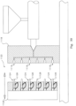
Figure 12 is a schematic block diagram of control components associated with control of the heating and transport of the preforms usable with any of the above described embodiments; -
Figure 13 is a side view of typical injection-moulded preform for stretch-blow-moulding of a polymer container. -
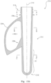
Figure 13A is a sectioned side view of a preform according to a preferred embodiment of the invention in which a central vertical plane passing through a central vertical axis of the preform lies in the plane of the paper, -
Figure 14 is a side view of a mandrel for injection-moulding the preform ofFigure 13A in which a central vertical plane passing through a central vertical axis of the mandrel lies in the plane of the paper; -
Figure 15 is cross section along the vertical central axis of the mandrel ofFigure 14 taken at the level of A-A; -
Figure 16 is a cross section along the vertical central axis of the mandrel ofFigure 3 taken at the level B-B; -
Figure 17 is a side view of a container stretch-blow-moulded from the preform ofFigure 2 ; -
Figure 18 is an end view of the container ofFigure 17 ; -
Figure 19 is a sectioned side view of a further preferred embodiment of a preform not formaing part of the claimed invention; -
Figures 19A and 19B are selected cross sections of the preform ofFigure 19 ; -
Figure 20 is a sectioned side view of a further preferred embodiment of a preform not forming part of the claimed invention; -
Figures 20A and 20B are selected cross sections of the preform ofFigure 20 ; -
Figure 21 is a sectioned side view of a further preferred embodiment of a preform according to the invention; -
Figures 21A and 21B are selected cross sections of the preform ofFigure 21 ; -
Figure 22 is a sectioned side view of a further preferred embodiment of a preform according to the invention; -
Figures 22A and 22B are selected cross sections of the preform ofFigure 22 ; -
Figure 23 is a sectioned side view of a further preferred embodiment of a preform not forming part of the claimed invention; -
Figures 23A and 23B are selected cross sections of the preform ofFigure 23 ; -
Figure 24 is a schematic view of an injection moulding process for producing the preforms ofFigures 13A and19 ,20 to 23 ; -
Figure 25 is a container with integral handle as blow-moulded from the preform ofFigure 13 , -
Figure 26 is a preform of reduced PET volume according to a preferred embodiment not forming part of the claimed invention, -
Figure 27 is a cross section view of the body of the preform ofFigure 26 showing variations in wall thickness, -
Figure 28 is a side view of a container stretch-blow-moulded from the preform ofFigures 26 and 27 , -
Figure 29 is a further side view of a preform with integrally formed handle according for stretch-blow-moulding in the machine of the invention, -
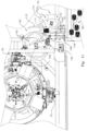
Figure 30 is a sectioned, schematic side view of an injection moulding press and injection moulding die for moulding the preforms for use in the continuous rotating stretch-blow-moulding machine of the invention, with the die opened prior to an injection moulding cycle, -
Figure 31 is a front view of the face of the moving die section of the injection moulding die ofFigure 30 at the end of an injection moulding cycle (with the heated fixed die section removed) -
Figure 32 is a further view of a part of the injection moulding press showing extraction of moulded preforms by vacuum elements inserted into the opened die by a robot. -
Figure 33 is a side view of a preferred embodiment of a preform and integrally attached handle, not forming part of the claimed invention. -
Figure 34 is an end view of the preform offigure 33 . -
Figure 35 is a view from above of the preform and handle ofFigures 33 and 34 . -
Figure 36 is a sectioned side view of a further preferred embodiment of a preform according to the invention; -
Figures 36A and 36B are selected cross sections of the preform ofFigure 36 ; -
Figure 37 is a sectioned side view of a further preferred embodiment of a preform according to the invention; -
Figures 37A and 37B are selected cross sections of the preform ofFigure 37 . - A feature of the
present machine 10, a preferred configuration of which is shown inFigure 3 , is that motion through the machine of a non-symmetric injection mouldedpreform 12 as shown inFigure 1 , from its initial intake to its emergence as a stretch blow-moulded container 14 (as shown inFigure 2 ), is continuous. As shown inFigure 1 , the previously injection moulded polymer preform comprises a cylindricalelongate body 16 andneck 18. Anintegral handle 20 extends from afirst junction point 22 just below theneck 18 to asecond junction point 24 on thebody 16 of the preform. - Referring again to
Figure 3 , the continuous, non-incrementing process of themachine 10 includes the transfer of preforms from a loading or pick offposition 26 to a preheatingstage 28, through the preheating stage and transfer to a stretch-blow moulding die 30 with subsequent removal of the blowncontainer 14 from the die and removal from the machine. These stages will now be described in detail. - As shown in the preferred layout of the
machine 10 inFigure 3 and referring also toFigures 4 and5 , the previously injection moulded preforms 12 (as shown inFigure 1 ) are fed, for example from a hopper (not shown but as well understood in the industry) to slide under gravity downinclined rails 32 while supported by theirnecks 18. The inclined rails 32 comprise a pair ofupper rails 32a between which the preforms are suspended by theirnecks 18, and a pair oflower rails 32b which constrain thehandles 20 of the preforms approximately in line with the long axis of the rails. For reasons that will become clear, it is essential however, that during the passage of preforms through the stages of the machine, the orientation of theintegral handle 20 of the preform is controlled precisely. -
Preforms 12 with a handle roughly oriented pass one by one through anescapement 34 to be captured by a continuously rotatingfeeder wheel 36 which carries the preform between the feeder wheel and ashort rail 40, in such a way that friction between thebody 16 of the preform and therail 40 induces rotation of the preform and its handle. The rotating handle collides with a stop 40a under therail 40 forcing each handle into a rearward orientation with respect to the direction of travel, to arrive at a pick offposition 26. - At the instance that a preform arrives at the pick of
position 26, a pair of opposing actuators (not shown) located under the pick offposition 26, simultaneously briefly close on, and then release, the preform handle 20 to fix its orientation relative thegripper 58 which, also at that instant engages with theneck 18 of the preform. - In this second preferred embodiment, with reference now to
Figure 4A , the injection moulded preforms 12 are again fed ontoinclined rails 32a, down which they slide under gravity supported by the flanges at thenecks 18. Again, as described for the first preferred embodiment above, the handles are loosely constrained betweenlower rails 32b, with the handles either in a "leading", that is pointing in the direction of movement of the preforms as they progress down the incline, or "trailing", pointing rearwardly. - In this second preferred embodiment an orientation mechanism 34A is located at a point along the
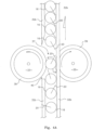
rails 32 approaching the lower end of the rails. As can be seen inFigure 4A , the mechanism includes two contra-rotatingdrive wheels rails 32, at a level coincident with the lowermost portion of the bodies of the preforms and below thelower rails 32b and the lowermost point of the handles. The axes of the wheels are normal to the slope of the inclined rails. Note only thelower rails 32b are shown inFigure 4A . - The
drive wheels gap 37 which is somewhat narrower than the diameter of thebody 16 of the preforms. Each of thewheels tyres 39 of a sufficiently soft polymer material to allow apreform body 16 to pass through the gap but providing a degree of grip on the body. - As shown in
Figure 4A ,drive wheel 33 rotates in an anticlockwise direction whiledrive wheel 35 rotates in a clockwise direction. The combination of these two rotations has the effect of drawing a preform through thegap 37. The two drive wheels do not however rotate at the same rate, with, in the preferred arrangement shown inFigure 4A ,drive wheel 35 rotating at a significantly lower rpm than that ofguide wheel 33. A preferred ratio of rotation ofdrive wheel 33 to drivewheel 35 is of the order of 2:1. - The effect of this differential in rate of rotation of the two drive wheels is that
drive wheel 35 exerts a considerably greater grip on thebody 16 of the preform so that it acts to rotate the preform in an anticlockwise direction as the preform passes through thegap 37 between the two drive wheels. By this means ahandle 20 of a preform which is in a leading position as the preform enters thegap 37, is rotated until it contacts the right-handlower rail 32b (as seen from above inFigure 4A ). To allow for this rotation of the handle agap 40 is provide in the left-hand lower rail. - It will be understood that the anticlockwise rotation induced by
drive wheel 35 has no effect on those preforms entering the gap with their handles trailing, except to drive the trailing handle into contact with the right-hand lower rail. Thus, all preforms downstream of the orientation mechanism 34A approach theescapement 34 in the preferred orientation with the handles in the trailing position. - The
escapement 34 controls the feeding of the handle oriented preforms to thefeeder wheel 36 as described above, retaining the trailing orientation of the handles as induced by the mechanism 34A. As for the first arrangement above, at the instance that a preform arrives at the pick ofposition 26, a pair of opposing actuators (not shown) located under the pick offposition 26, simultaneously briefly close on, and then release, the preform handle 20 to fix its orientation relative thegripper 58 which, also at that instant engages with theneck 18 of the preform. - It will be understood that although the above description is specific to the rotation of the preform in an anticlockwise direction by the clockwise rotating drive wheel, orientation according to the principles of the mechanism may equally be achieved by reversing the differential rates of rotation of the two drive wheels and providing the gap in the lower guide rail on the opposite side to that illustrated in
Figure 4A . In this alternative arrangement, it is then the anticlockwise rotating drive wheel which induces clockwise rotation to the body of a preform passing between the wheels, rotating a leading oriented handle until it contacts the left-hand lower rail (as seen from above inFigure 4A ), the gap allowing rotation of the handle then being provided in the right hand lower rail. - Precise orientation of the handle throughout the stages of the machine is critical to the process of preheating where the orientation must align with the alignment of heat shields, and for correctly placing the preform and the handle into the stretch-blow-moulding die.
- With reference now to
Figures 4B to 4D , in this further preferred arrangement of a handle orientation mechanism 34b, injection moulded preforms 12 emerge one at a time from a bulk supply via, for example, a conveyor (not shown) to be deposited centrally onto a pair of contra-rotating, downward slopingrollers rollers body 16 and handle 20 of each preform to drop through the gap between them but retain the wider diameter of the projecting collar below theneck 18 of the preform. Therollers guide rails 15 and 17 (as best seen inFigure 4D ) similarly spaced as the gap between the rollers. As the bodies and the handles of the preforms drop through the gap between the rollers and that between the guide rails 15 and 17, thehandles 20 are constrained into approximate alignment between these rails, but at this stage handles may be "leading" or "trailing" relative to movement in the downward direction shown inFigures 4C and4D . Since it is a requirement imposed by the design of the blow-moulding machine described below, that preform handles at entry of preforms into thefeeder wheel 36 must be in the trailing position, those leading must be turned around. - At the downward ends of the rollers, the preforms drop to the level of main support rails 19 and 21, so that preforms are now retained between these main support rails by their collars. A combination of gravity and pressure from following preforms forces each preform against the upward outer ends of side by side, contra-rotating auger screws 23 and 25 located on either side of a median vertical plane between the support rails. The
flutes 27 of the auger screws are sized so as to capture between them thenecks 18 of the preforms. The pitch of the auger screws is such as to separate preforms while being driven in the downward direction by the screws' rotation. - Generally coextensive with the length of one of the auger screws, (in the arrangement shown in the drawings, auger screw 25), the
main support rail 21 is provided at its underside with a friction strip 29 (as best seen in the enlargement inset ofFigure 4D ). Thisfriction strip 29 projects slightly into the gap between the main support rails 19 and 21 so that its inner edge engages with the body of a preform as it progresses between the augers. This friction contact urges rotation of the preform in an anticlockwise direction as seen from above. - Also approximately coextensive with the length of the
auger screw 25 is a gap in theguide rail 17. Any rotation of an already trailing handle, will only force the handle into engagement with theopposite guide rail 15, and remain trailing. But, as can be seen from the enlarged inset ofFigure 4D , handles of preforms with handles leading at entry between the auger screws will gradually be rotated from the position where the handle is leading to it being in the trailing position, (being free to do so by the gap in guide rail 17) until these handles also are arrested from further rotation by theopposite guide rail 15. From here as can be seen fromFigures 4C and4D , the preforms, all with handles trailing, proceed down the main support rails 19 and 21 with the handles constrained between the nowcontinuous guide rails feeder wheel 36. - As well as spacing and rotating preforms as they pass between the auger screws 23 and 25, the rotation rate of the auger screws is such as to deliver a preform to the
feeder wheel 36 in synchronization with the rotation of that wheel. Furthermore, the rotation of the auger screws provides pressure to ensure preforms proceed down the main support rails. - Referring now to
Figure 5 andFigure 6 , a firstrotating transfer system 42 is positioned adjacent thefeeder wheel 36 with a continuously rotatingcarrier 44 of the firstrotating transfer system 42 and thefeeder wheel 36 contra-rotating one to the other. - The rotating
carrier 44 of the firstrotating transfer system 42 includes, in this embodiment, four opposingsupport arms 46 extending radially from a fixed centre ofrotation 48 to rotate about avertical axis 50. Each end of the arms carries a first pick andplace apparatus 52. Each first pick andplace apparatus 52 includes alinear guide 54, ahousing 56 which is rotatably mounted to the outer end of thesupport arm 46, enabling rotation of thehousing 56 about avertical axis 51. A two-fingeredgripper 58 is mounted to arotary actuator 60 supported byvertical plate 62 at an outer end of a free slidingelement 64 of thelinear guide 54. Thegripper fingers 66 are centred on a gripper effectivevertical axis 68, with the gripper able to be rotated about thehorizontal axis 61 of therotary actuator 60. - A fixed
horizontal cam plate 70 is mounted at a level below the rotatingcarrier 44 so that its centre is coincident with thevertical axis 50 of the rotating carrier. Theperimeter edge 72 of thecam plate 70 forms anouter cam surface 74 and its upper surface 76 is provided with acam channel 78 which is inboard of theperimeter edge 72 and theouter cam surface 74. - The
housing 56 of thelinear guide 54 is provided with anoutrigger arm 80 extending radially from the centre ofrotation 82 of thelinear guide 54. The outer end of theoutrigger arm 80 supports afirst cam follower 84 locating in thecam channel 78. The free slidingelement 64, adapted to reciprocating linear motion in a horizontal plane, is provided with asecond cam follower 86 with the free slidingelement 64 biased bysprings 88 to maintain contact between thesecond cam follower 86 and theouter cam surface 74. - The
cam channel 78 andouter cam surface 74 are arranged so that as a first pick andplace apparatus 52 rotates past the preform pick offposition 26, the rotation of the rotatingcarrier 44, combined with the loci of the first andsecond cam followers gripper 58 to be both reciprocatingly extended and retracted, and rotated relative thearm 46. The gripper motion is such that at the approach to the preform pick offposition 26, the free slidingelement 64 and thus thegripper 58 is extended followed by rotation of thelinear guide 54 andgripper 58 in retrograde or negative direction relative to the direction of rotation of the rotatingcarrier 44. - At the instant a
preform 12 arrives at the pick offposition 26 after its approximate orientation, so that thehandle 20 of the preform is trailing but not yet fixed, the extending movement of thegripper 58 through thefirst cam follower 84 against theouter cam surface 74, brings the grippereffective axis 68 into coincidence with the central axis of the preform. At this instance also, a pair of opposing actuators located under the pick offposition 26 simultaneously briefly close on, and then release, the preform handle 20 to fix its orientation relative thegripper 58 which, also at that instant engages with theneck 18 of the preform. Thegripper 58 is then rotated positively to carry thepreform 12 clear of the supportingshort rail 40 and away from the pick offposition 26. - This combination of reciprocating rotation and extension and retraction of the
gripper 58 compensates for the divergence of the loci of the supportingtooth formation 38 of thefeeder wheel 36 and the rotatingcarrier 44 as they contra rotate one relative the other. It is by the means of the reciprocating rotation and retraction movements of the gripper through a combination of a rotating linear guide and the two cam loci that a smooth continuous transfer of preforms is possible between two rotating elements; that of thefeeder wheel 36 and the rotatingcarrier 44. - With reference now to
Figure 7 , rotation of the rotatingcarrier 44 brings apreform 12 retained in agripper 58 to the preheatingstage 28 as was shown inFigure 3 of themachine 10. Because the preheating of the preforms is conducted with the preforms inverted from their initial position at the pick offposition 26, that is, with theneck 18 upward, therotary actuator 60 at the end of the free slidingelement 64 rotates thegrippers 58 and the preforms through 180degree during their transit between pick offposition 26 and the transfer to a preheatingtransport system 90. The effect of this rotation is that thehandle 20 of the preform is now "leading" with respect to the direction of rotation of the rotatingcarrier 44, instead of trailing as it was at the pick offposition 26 as could be seen inFigure 5 . - The preheating
transport system 90 is also in continuous movement and comprises aloop rail system 92 with proximate and distalrotating guide wheels preform supporting mandrels 98 are adapted to move around theloop rail system 92, driven into motion around the straight sections of the loop by a drive chain (not shown) to which they are fixed and around theguide wheels niches 103 of the guide wheels. As well as travelling around theloop rail system 92, themandrels 98 are continuously rotated about their vertical axes. - Preheating of the
preform 12 is required for thebody 16 of the preform, that is for that portion of the preform which will be subjected to stretching and blow-moulding, to sufficiently soften the polymer. But thehandle 20 and theneck 18 which retain their as injection moulded form in the blown container shown inFigure 3 , must be protected from excessive heat as the preform moves through the preheating stage. For this reason, as shown inFigure 8 , apreform supporting mandrel 98 is provided with aheat shield 100 comprising achannel 102 rising from acylindrical collar 104 in which thehandle 20 is protected while theneck 18 is protected by its insertion into thecylindrical collar 104 of the mandrel. - It may be noted that the patterns of the
outer cam surface 74 and that of thecam channel 78 of the firstrotating transfer system 42 as shown inFigure 5 , near the pick offposition 26 differ from those at the approach to, and following the preform transfer to preheatingposition 106. This reflects the difference in movements required of agripper 58 as it steers the preform into the position in which the vertical axis of the preform becomes aligned with that of thecylindrical collar 104 of themandrel 98 and thehandle 20 is aligned with theheat shield channel 102. At the instant these axes are aligned and thehandle 20 of the preform is aligned between the side elements of thechannel 102, acylindrical plunger 108 within thecollar 104 rises into theneck 18, then lowers to bring the neck to an inserted position within the collar. These movements of course take place while the firstrotating transfer system 42 and theproximate guide wheel 94 are in continuous contrarotation. This complex movement is again made possible by the combination of the rotation of thearm 46 and the rotation and linear movements of the free slidingelement 64, and thus of thegripper fingers 66 of the first pick andplace apparatus 52. - Thus the transfer of a preform from the gripper of the
first transfer system 42 to apreform supporting mandrel 98 is achieved in one fluid motion as the vertical axis of the preform is brought into alignment with that of the mandrel and the oriented handle of the preform slides into the heat shield, while accommodating each of the rotations of the loop rail, the mandrel and the transfer system as well as the movements of the gripper. - As best seen in
Figures 3 and8 ,banks 110 ofheating elements 109 are positioned along each of the straight sections of theloop rail system 92. Gradedhot air 111 is drawn across the path of thepreforms 12 byextractor fans 113. To prevent excessive heat build-up of thecylindrical collar 104 and theneck 18 of the preform in the collar, a coolingair stream 115 is directed at the collars. - As a
mandrel 98 and preform 12 are rotated away from the transfer-to-preheatingposition 106 by the proximaterotating guide wheel 94, the mandrels supported in the chain of the preheatingtransport system 90 travel along the firststraight section 112, around the distalrotating guide wheel 96 and back along the secondstraight section 114 to arrive at a transfer-from-mandrel position 116. While traversing these straight sections, the mandrels are rotated about their vertical axes by agear 105 of the mandrel engaging withchain 107 to evenly expose the bodies of the preforms to heat from thebanks 110 ofheating elements 109. Theheating elements 109 are each arranged as a series of infra-red heating elements which are individually adjustable as to their proximity to the passing preforms. - It will be understood that the orientation of each
mandrel 98 at both the transfer to preheatingposition 106 and at the transfer frommandrel position 116 is critical to allow the respective first and second transfer systems to insert and extract a preform handle from the channel of the mandrel's heat shield. These heat shield orientations with respect to the periphery of theproximate guide wheel 94 are not the same at these two positions so that the orientation of the mandrel and its heat shield need to be changed from that demanded at the handle extraction position to that required at the handle insertion position. - To this end, each mandrel is provided with a
guide carriage 98a fixed to the mandrel. As a mandrel approaches the transfer-from-mandrel position 116,cam followers proximate guide wheel 94, thecam followers position 106. - With reference now to
Figure 9 , a second rotating transfer system 118 operates to transferpreforms 12 from the preheatingtransport system 90 to a stretch blow moulding dieassembly 120. The stretch blow moulding dieassembly 120 comprises of four stretch blow moulding dies 30, two of which can be seen in the truncated view of the machine inFigure 9 . In the present embodiment, four radially disposed stretch blow moulding dies 30 rotate continuously about acommon centre 122. - The second rotating transfer system 118 is of similar configuration to that of the first
rotating transfer system 42 described above. That is, it includes acam plate 124, also provided with an inboard cam channel 126 and anouter cam surface 128 around its periphery. - In this instance, second rotating transfer system 118 includes two, rather than four, continuously rotating opposing
radial arms 130, each of which carries a second pick andplace apparatus 132. Again, similar to the first pick andplace apparatuses 52 of the firstrotating transfer system 42 above, each includes a linear guide rotatably mounted to the respective outer end of theradial arm 130, with the free sliding element of the linear guide supporting a rotary actuator which, in turn supports a gripper. In this arrangement also, a first cam follower of an outrigger arm attached to the housing of the linear guide, locates in the inboard cam channel 126, while a second cam follower of the free sliding element of the linear guide remains in contact with theouter cam surface 128 by means of a spring. - Preforms still retained in
preform supporting mandrels 98 arrive back at the rotatingproximate guide wheel 94 of the preheating system and approach the transfer-from-mandrel position 116, and are rotated into the required orientation of the heat shield as explained above. Thecylindrical plunger 108 of amandrel 98 approaching the transfer-from-mandrel position 116, lifts the preform so that the neck is clear of thecylindrical collar 104 to allow the gripper of the second rotating transfer system 118 to engage the preform by the exposedneck 18. Again, it is the motion of the gripper induced by the combination of rotation of theradial arm 130, the rotation of the linear guide and linear movements of the free sliding element supporting the gripper as controlled by the cam channel 126 andouter cam surface 128, which allows the preform and its handle to be smoothly removed from the preheatingtransport system 90. - As one rotating
radial arm 130 of the second rotating transfer system 118 approaches and removes a preform from the preheatingtransport system 90, the opposite radial arm approaches thedie loading position 134. During its rotation from the transfer-from-mandrel position 116 to thedie loading position 134, the rotary actuator of the second pick andplace apparatus 132 rotates about its horizontal axis to change the preform from its inverted position held during the preheating stage, back into an upright position. (It should be noted thatFigure 9 shows both arotating arm 130 and a stretch blow moulding die 30 approaching the die loading position 134) - Stretch blow moulding dies of the
die assembly 120, are in the form of two diehalves 136, one of which is shown inFigure 10 . Die halves 136 are hinged together about avertical axis 142 in the manner of a bivalve, and with the hinge supported from acentral structure 146 of thedie assembly 130 in a typical arrangement for radial stretch-blow-moulding machines. Theface surface 138 of the die half shown inFigure 10 has been shaded to highlight thedie cavity 148 for thebody 16 andintegral handle 20 of the preform. As is common in the stretch-blow-moulding of containers, theneck 18, which remains unaltered in the stretch-blow-moulding process, projects out of the die when closed. - Referring again now to
Figure 9 , as stretch-blow-moulding dies 30 approach theloading position 134 the die halves open symmetrically about a bisectingradial line 152 passing through the centre ofrotation 122 and thevertical axis 142 of the die hinge 144, in preparation for receiving a preform. It may noted fromFigures 3 and9 , that the rotation centres of the second rotating transfer system 118, the proximaterotating guide wheel 94 of the preheating stage and that of the stretch-blow-moulding die assembly 120, lie along astraight line 154. - As an opened die 30 approaches the
die loading position 134 lying on thestraight line 154, aradial arm 130 with a preform retained in the gripper of the second pick andplace apparatus 132 also approaches the loading position. As the bisectingradial line 152 of the die halves 136 becomes coincident with thestraight line 154, the movements of the second pick andplace apparatus 132 has brought the gripper effective vertical axis and thus the vertical axis of the preform into coincidence with theaxis 156 of the die (as defined by the centre of the preform body when held in the die) and with the handle oriented to lie in the vertical plane defined by thestraight line 154. While the die halves close and the paths of thedie 30 and the end of therotating arm 130 begin to diverge, the rotation and extension of the gripper, still holding theneck 18 of the preform, ensures the orientation of the handle is maintained in that vertical plane defined by the bisecting line of the die halves until closure is complete. The gripper then disengages from the preform neck. - It can be seen from
Figure 10 , that the curved section of thehandle 20 of the preform is nested in a constrictingcavity 150 of the die which ensures that the handle is not distorted, nor the region between the junction points 22,24 stretched. The underside of the straight section of the handle forms a surface which, in effect, determines the shape of the container under the handle. - With the die halves 136 closed, stretch-blow-moulding of the container proceeds and the die 30 loaded at the
die loading position 134 rotates towards thedie unloading position 158 as shown inFigure 11 . - A third
rotating transfer system 160 is located adjacent the stretch-blow-moulding die assembly 120, and is configured in similar manner to that of the first and second rotating transfer systems 42,132 described above. As for the secondrotating transfer system 132, the thirdrotating transfer system 160 includes opposingradial arms 162 at the ends of each of which is a third pick andplace assembly 164. It does not however include a rotary actuator since the container which emerges from the die remains in an upright position through the discharge process. - As for the first and second rotating transfer systems, movements of a
gripper 166 is controlled by a combination of the rotation of the opposingradial arms 160, the linear movement of the free element of the linear guide and the two cam loci. - As the stretch-blow-
moulding die 30, now containing afinished container 14, nears thedie unloading position 158 lying on the line 168 joining the centres of rotation of the stretch-blow-moulding die assembly 120 and of the opposingradial arms 160 of the third transfer system, the gripper of the pick and place is maneuvered into position to grasp the neck of the container. As the die reaches the die unloading position, the die halves open and the gripper extracts the blowncontainer 14 from thedie 30. - The third
rotating transfer system 160 continuous to rotate, tanking thecontainer 14 held by thegripper 166 into adischarge channel 172, with the base of the container passing over aguide rail 170.Guide rail 170 transitions from concentricity with the third rotating transfer system to concentricity with a rotating two-tiered outfeed wheel 172. As thecontainer 14, now in thedischarge channel 172, reaches arelease position 174 lying on theline 176 joining the centres of rotation of the thirdrotating transfer system 160 and that of theoutfeed wheel 172, thegripper 166 releases the neck and retracts. At the same time ascalloped indentation 172a of the rotating outfeed wheel captures the body of the container feeding it into adischarge channel 178. As containers follow the path of thegripper 166 and then a path determined by theoutfeed wheel 172, the base of the container receives cooling air fromorifices 182 inguide rail 170, backpressure from accumulating containers in thedischarge channel 172 force containers to drop into acontainer receiving bin 180. - The operation of the
machine 10 is under the control a programmable logic controller. As well as ensuring that all rotation drive servo motors operate synchronously, the controller provides for fully adjustability of the parameters of the preheating elements and of the parameters of the stretch-blow-moulding dies. This includes setting differential temperature gradients allowing for a gradually increasing exposure to heat as preforms progress around the preheating transport system, and automatic adjustment of heating element temperatures for changing ambient temperatures. - Control of the preheating is particularly critical in the present system because of the unique characteristics of the preform dictated by the integral handle of the preform. The preheating is thus designed to allow for lateral flow of material in the area between the two junction points of the handle while limiting longitudinal flow and extension during the stretching phase of the stretch-blow-moulding process. Instead, the manner in which heat is applied to the preform ensures that the bulk of polymer which forms the outer shell of the container of
Figure 2 , is produced from that region of the preform below the lower junction point of the handle. -
Figure 12 is a schematic block diagram of control components associated with control of the heating and transport of the preforms usable with any of the above described embodiments. - As best seen in the inset of
figure 12 ,banks 110 ofheating elements 109 are positioned along each of the straight sections of theloop rail system 92. Gradedhot air 111 is drawn across the path of thepreforms 12 byextractor fans 113. To prevent excessive heat build-up of thecylindrical collar 104 and theneck 18 of the preform in the collar, a coolingair stream 115 is directed at the collars. - In a preferred form each
bank 110 comprises amodule 201. Themodules 201 are arranged sequentially around theconveyer 202 as illustrated infigure 12 . - In a preferred form a
processor 203 in conjunction withmemory 204 executes a program for control of theheating elements 109 of themodules 201. - In a particular preferred form each
element 109 of eachmodule 201 is controlled individually by theprocessor 203. - In an alternative preferred form of the
elements 109 are controlled as a group based on height - so the topmost elements 109 of themodules 201 are controlled to a predetermined temperature together whilst the next down in height elements 109B are also controlled together to a predetermined temperature - and so on down to elements 109G at the lowest level. - In addition, the
processor 203 controls the speed of rotation ofmotor 205 in order to control the continuous speed of thepreforms 16. - A
temperature sensor 206, in one form an infrared temperature sensor provides environment temperature sensing which is utilised byprocessor 203 to modulate the degree of heating of allelements 109 by a difference factor delta (Δ). - This allows for a global control of the system temperature in response to variations in ambient temperature.
- As noted above, the stretch-blow-moulding machine is especially developed for, and adapted to, the feeding and transportation of a non-symmetrical preform with integral handle and, ultimately the stretch-blow-moulding of that preform into a container with an integral handle. The preform according to the invention may take a number of different forms described below, although common to all are the
neck portion 18 and theintegral handle 20 as shown inFigure 1 . - The preforms now to be described differ primarily in respect of the configuration of their internal surfaces, offering benefits of improved distribution of polymer material to the walls of the blown container as well as significant improvement in economy of manufacture due to reductions in the volume of polymer required.
- In a first preferred a
preform 310 according to the invention as shown inFigure 13A includes afinished neck portion 312 and a tubularhollow body portion 314 extending from below the neck portion. Similar to preforms of the prior art, the outer surfaces of thebody portion 314 are defined by diameters centred on a centralvertical axis 316, so that thebody portion 314 approximates a cylinder but with a decrease in diameters from theneck portion 312 to theclosed end 318 of the preform. - The internal surfaces of the
preform 310 include surfaces of thehollow body portion 314 which are not concentric with the outer surfaces. Preferably, as shown inFigures 15 and 16 , cross sections of the internal surfaces of thepreform 310 are circular and concentric in theneck portion 312 of the preform as indicated by the cross section A-A, but below the neck portion are of ovoid form as indicated by section B-B. All sections are however centred on the centrallongitudinal axis 316 of the body of the preform. - Referring now to
Figure 14 , in a preferred arrangement, themandrel 322 around which thepreform 310 is injection moulded, comprises anupper region 324 of circular cross sections adapted to position and retain the mandrel in its correct position in an injection moulding cavity. A first preform-definingportion 326 of the mandrel extends from thisupper region 324 to a depth equal to that of theneck portion 312 and is of circular cross section A-A as shown inFigure 4 to form the concentric walls of the neck portion. Theovoid portion 328 of the mandrel depends from thefirst portion 326, extending to thetip 330 of the mandrel. - Given the ovoid shape of the cross sections of the
ovoid portion 328, there is a short transition portion of the mandrel immediately belowportion 326 forming the internal form of the neck portion, which transitions from the circular cross section A-A ofportion 326 to the ovoid sections B-B. This transition thus takes the form an asymmetrical frustum of a cone; an upper end of which has a diameter equal to that of a lower end of thefirst portion 326 with the lower end of the transition portion conforming in cross section to the upper end of the ovoid cross section B-B of the remaining length of the preform. - It can be seen from
Figure 13A , that both the outer surfaces of thebody portion 314 of the preform and the ovoid portion of the inside surfaces as defined by themandrel 322, are tapering; that is, the diameters defining the external surface of the preform are decreasing from below theneck portion 312 to the bottom 318, while similarly, themajor axis 344 and theminor axis 342 of the cross sections of theovoid portion 328 also decrease accordingly. - Referring still to
Figure 13A , thepreform 310 of the invention further includes, as noted above, anintegral handle 334 which forms a loop of material extending vertically from anupper junction 336 below theneck portion 312 to alower junction 338 with the outer surface of the preform. Thehandle 334 is centred on and defines a central vertical plane 340 (lying in the plane of the paper) which contains the centrallongitudinal axis 316 of the preform. - The
mandrel 322, and thus the internal surfaces of theovoid portion 328, are so oriented relative thehandle 334, thatmajor axis 344 of the ovoid cross section B-B lies in the centralvertical plane 340. - It can thus be seen from
Figure 16 and cross section B-B that the wall thicknesses of thepreform 310 in thatportion 328 of the preform in which the inner surfaces are defined by the ovoid cross section, varies from a maximum at opposite ends of theminor axes 342 of the ovoid cross section to minimum thicknesses at outer ends of themajor axis 340. Preferably, the ratio of maximum wall thickness to minimum wall thickness of the ovoid portion lies in the range of 2:1 and 2.2:1. - The distribution of polymer in the preform according to the invention, afforded by the non-symmetry of the ovoid portion, allows polymer walls of the preform in the region of maximum thickness to be biased predominantly towards the
longer side walls 346 of a rectangular cross section blowncontainer 348, while the polymer walls of the preform from the region of minimum thickness is predominantly distributed towards theshorter side walls 350 of the blown container such as shown inFigures 17 and 18 . It can be seen fromFigures 17 and 18 that thelonger side walls 346 lie on either side of the centralvertical plane 340 and thus thehandle 334 so that the alignment of themajor axis 344 with thevertical plane 340 ensures that the polymer from regions of maximum wall thickness are directed to those longer side walls. In preferred forms the preform of the first embodiment is produced by an injection moulding process as described earlier in this specification. In preferred forms the preform thus produced is reheated and blown on a continuously rotating, non-symmetric preform feed, stretch-blow-moulding machine as described earlier in this specification. - With reference now to
Figure 19 , in this preferred embodiment not forming part of the claimed invention, theexterior surface 410 of thepreform 400, is of substantially cylindrical form. As for the first embodiment above, it too includes an integrally injection mouldedhandle 434. In this embodiment, theinternal surfaces 414 of the preform are consistently circular in section as shown in the two sample cross sections Figure 17A and Figure 17B. However, again as is clear from the two cross sections and the sectioned side view ofFigure 17 , there is a tapering of theinternal surface 414 so that the wall sections, though concentric to the external surface, increase from a minimum thickness at theneck portion 412 of the preform to a maximum proximate itslower end 418. In preferred forms the preform of the second embodiment is produced by an injection moulding process as described earlier in this specification. In preferred forms the preform thus produced is reheated and blown on a continuously rotating, non-symmetric preform feed, stretch-blow-moulding machine as described earlier in this specification. - In this further preferred embodiment not forming part of the claimed invention, a
preform 500 as shown inFigure 20 , is formed to significantly reduce the volume of material required to produce the containers shown inFigures 17 and 18 . As in the embodiments above, thepreform 500 includes an injection mouldedintegral handle 534. Although in this embodiment, theneck portion 512 is identical in its exterior and internal forms to that of the earlier embodiments, there is a substantial reduction in the diameter of the substantially cylindrical portion of the body of the preform below the neck portion. - In this embodiment also, as in the second preferred embodiment above, the internal surfaces of the preform are consistently circular in section as shown in the two sample cross sections A and B of
Figures 20A and 20B , but taper with the wall sections increasing from the minimum thickness obtaining in the neck portion and through the transition in diameters below the neck portion, to a maximum wall thickness proximate thelower end 518 of the preform. - As a further means of reducing the volume of material in the preform of this embodiment, the
outer surface 510 below theneck portion 512, also tapers towards thelower end 518. In preferred forms the preform of the third embodiment is produced by an injection moulding process as described earlier in this specification. In preferred forms the preform thus produced is reheated and blown on a continuously rotating, non-symmetric preform feed, stretch-blow-moulding machine as described earlier in this specification. - With reference now to
Figure 21 , this preferred embodiment of apreform 600 according to the invention, shares a number of characteristics with that of the first and second preferred embodiments above. It has, (as have all the preform embodiments of the present invention), anintegral handle 634 as previously described, and, as in the first preferred embodiment above, theinternal surfaces 614 of the preform are not consistently of circular section throughout the length of the preform. However, theexternal surfaces 610 of the perform are substantially cylindrical in form as in the second preferred embodiment. - Thus, although the
external surfaces 610 are defined by circular cross sections, theinternal surface 614 varies from circular in cross section from the neck portion 612 down to section A-A inFigure 21A , to then transition to an ovoid section B-B as shown inFigure 21B , approaching thelower end 618. - A feature of this particular embodiment is that the wall thickness of the ovoid portion of the
internal surface 614 of the perform at the ends of the major axes remains constant with the wall thicknesses of the concentric cross sections from section A-A and upwards, while there is a thickening of the walls increasing to maximum at the minor axis of the ovoid cross section. In preferred forms the preform of the fourth embodiment is produced by an injection moulding process as described earlier in this specification. In preferred forms the preform thus produced is reheated and blown on a continuously rotating, non-symmetric preform feed, stretch-blow-moulding machine as described earlier in this specification. - The preform of this embodiment of a
preform 700 shown inFigure 22 is similar to that of the fourth preferred embodiment above, but here, as shown in the cross section views A-A and B-B ofFigures 22A and 22b , the wall thickness at the outer ends of the major axes of the ovoid cross section portion of the preform is not maintained equal with the wall thickness of at and below theneck portion 712. Rather the wall thickness gradually increases from below the neck portion towards thelower end 718 of the preform. - It may be noted at this point, that in those forms of the perform as in this embodiment and that of the first preferred embodiment above, shaping the internal surface in these non- concentric forms of outer and inner surfaces, introduces considerable issues for the injection -moulding of the preforms.
- As shown in
Figure 24 , preforms, including those of the present invention, are typically injection moulded in multi-cavity dies 800 in which thecavities 820 in the die conform to the outer shape of the preform, including in the present cases, the shape of the integral handle. In preforms with concentric wall thicknesses, that is, with circular cross sections, themandrels 840 for forming the internal surfaces will also be of circular cross sections. Thus, the only requirement for positioning such a mandrel relative the injection-moulding cavity is its concentricity with the neck portion of the cavity. - A mandrel for producing an internal surface of a perform which is wholly or partially non-circular in section may firstly require, a considerably more complex machining operation and, secondly it must be specifically oriented in the injection-moulding cavity.
- Mandrels for preforms with non-circular cross sections must be positioned within the cavities of an injection-
moulding die 820, one half of which is shown inFigure 24 so that the major axes of the ovoid portion are aligned relative to a vertical central plane of the cavities. For preforms according to the present invention with integral handles, that vertical plane is the plane on which the handle of the preform is centred as set out above (in effect theface 842 of the die half). - To be effective in biasing polymer material flow from different wall thickness areas of the preform towards designated regions of the blown container, the orientation of the preform must be maintained in the cavity of the stretch-blow-moulding machine. That is, the vertical plane of the preform must coincide with a defined vertical plane of the container. In the present invention the vertical plane of the preform is defined by the integral handle and is made coincident in the stretch-blow-moulding cavity with the central vertical plane of the blown container which again is central to the integral handle of the container.
- In a moulding cycle, the die halves are brought together to close the die and the array of
mandrels 840 driven into thecavities 820. Theinjection nozzle 848 is then advanced into theinjection pocket 844 and molten polymer forced through therunner system 846 to fill the spaces between the external surfaces of thecavities 820 and themandrels 840 to produce the preforms. - Although the above description has focused in some embodiments on use of ovoid or offset cross sections to vary the wall thicknesses of at least a portion of a preform at any given cross section of that portion, it will be understood that such variation can be achieved with other non- concentric shaping of the mandrel. Again, although the ovoid cross sections described for the preferred embodiment are centred on the vertical axis of the preform, other material distribution effects may be achieved by an asymmetric positioning of these cross section. In preferred forms the preform of the fifth embodiment is produced by an injection moulding process as described earlier in this specification. In preferred forms the preform thus produced is reheated and blown on a continuously rotating, non-symmetric preform feed, stretch-blow-moulding machine as described earlier in this specification.
- This further preferred embodiment of a preform not forming part of the claimed invention and shown in
Figure 23 , thepreform 900 is provided with a wall thickness 911 in the region between thejunction points handle 934 specifically to optimise control of the material in this region in the stretch-blow-moulding stage of producing a container from the preform. - In this embodiment, the
external surface 910 of the preform is again substantially cylindrical. The internal surface of the preform is likewise formed of circular cross sections, but as can be seen in both the side sectioned view ofFigure 13A and cross section AA ofFigure 13A , the centres of a portion of the cross sections (typified by section A-A) do not lie on thecentral axis 930 of the body of the preform, but are offset towards thehandle 934. - The effect is to "thin" the wall thickness in the region between the
junction points - It will be understood that all the above embodiments of the preform seek to optimise both the distribution of the polymer material of the preform into the blown container and do so by reducing the weight and thus the volume of material for reasons of economy of production. In preferred forms the preform of the sixth embodiment is produced by an injection moulding process as described earlier in this specification. In preferred forms the preform thus produced is reheated and blown on a continuously rotating, non-symmetric preform feed, stretch-blow-moulding machine as described earlier in this specification.
- With reference to
Figure 26 and 27 , apreform 1000 for stretch-blow-moulding thecontainer 1040 shown inFigure 28 , is comprised of aneck portion 1012, acollar 1014 and abody 1016 extending from below the collar. As in the preform according to prior art shown inFigure 1 , thepreform 1000 includes anintegral handle 1018 joined to thebody 1016 atfirst junction position 1020 just below thecollar 1014 and asecond junction position 1022 along the length of the body. - The first
cylindrical portion 1024 of the body extending below thecollar 1014, is substantially of constant diameter, and in the region immediately below the collar, the diameter is substantially that of the finished container as can be seen inFigure 28 . - But it can be seen firstly from a comparison between the
preform 1000 according to the present invention, and the preform of the prior art, that there is a significant reduction in diameter of thebody 1016 below the firstcylindrical portion 1024. - Furthermore, it is clear that this
second portion 1026 of the body, between the reduction in diameter and thetangent line 1028 with thebottom portion 1030, is not cylindrical but forms a portion of a narrow cone, with thebase diameter 1030 of the cone, that is its largest diameter, significantly smaller than the diameter of the firstcylindrical portion 1024. Thus, this large reduction in diameter and the tapering provide a first significant reduction in the volume of PET contained in the preform of the invention. - Turning now to the cross-section view of
Figure 27 , the walls of thebody 1016 of thepreform 1000, vary considerably in thickness. While the wall thickness of theneck portion 1012 and thefirst portion 1024 below thecollar 1014 are substantially of a constant thickness, that of thesecond portion 1026 varies from a relatively thin wall section at thebase diameter 1030, to a maximum thickness proximate thetangent line 1028. - The wall thickness of the
bottom portion 1032 is further varied, being reduced from the maximum thickness at thetangent line 1028 to a minimum at the base of the bottom portion. - This thinning of the wall thickness in the region below the
maximum diameter 1030 of thesecond portion 1026, augments the reduction in material volume provided by the diameter reduction and the form of thesecond portion 1026. - As well as providing savings in material volume, these variation in wall thicknesses are designed to evenly distribute the volume of PET material to various areas of the walls of the stretch-blow-moulded
container 1040 shown inFigure 28 , to an average thickness of approximately 0.5mm. In preferred forms the preform of the seventh embodiment is produced by an injection moulding process as described earlier in this specification. In preferred forms the preform thus produced is reheated and blown on a continuously rotating, non-symmetric preform feed, stretch-blow-moulding machine as described earlier in this specification. - With reference to
figures 33, 34 and 35 there is illustrated a preform having an integral handle with a flared portion thereby to impart an ergonomic aspect to the lifting of containers blown from the preform. - Turning now to
Figure 33 , in a preferred form of the preform, apreform 2100 includes aneck 2102, abody portion 2103 and ahandle 2113. Theneck 2102 has a threadedportion 2104 and alocating ring 2105. The preform is injection moulded from PET material in accordance with the teaching elsewhere in this specification. The handle in its configuration as injection moulded in its preform state, remains unaltered by the stretch blow-moulding process forming the resulting container from the continuous blow moulding process described elsewhere in this specification. - In order to produce the container, the
preform 2100 shown inFigures 33 to 35 , is fed into a blow moulding machine such for example as themachine 10 shown schematically inFigure 3 , and blow moulded according to bi-axial orientation blow moulding techniques. During this process theneck 2102 is held in amandrel 322, as shown inFigures 14 of a transport system of themachine 10 in such a way as to prevent its expansion in the stretch blow-moulding die 30. - The loop of orientable material forming the
handle 2113 has a generally uniform cross section from proximate thelower connection region 2116 to a gradually wideningcross section 2124 approaching theupper connection region 2115 with the cross section reaching and maintaining a maximum width proximate theupper connection region 2115 as can be seen inFigures 34 and 35 . - With reference again to
Figure 33 , integrally moulded first, second andthird strengthening elements upper connection region 2115, thelower connection region 2116 and at the junction between thestraight section 2118 and thearcuate section 2120 of thehandle 2113. - The
first strengthening element 2135 at theupper connection region 2115 comprises a curved strengthening element conforming generally in width and in cross section to the width and cross section of the widenedportion 2124 of the handle proximate the upper connection region. The curved strengthening element extends from a firstseparate connection region 2140 on thebody portion 2103 of the preform (and on the blown container) below theupper connection region 2115 and merges with the loop of orientable material proximate afirst end 2141 of the maximum width of the handle. - The
second strengthening element 2136 at thelower connection region 2116 of the handle, comprises a straight strengthening element conforming generally in width and cross section with the width and cross section of thestraight section 2118. The straight strengthening element extends from a secondseparate connection region 2142 above thelower connection region 2116 of the straight section of the handle, to merge with the straight section of the handle proximate the lower connection region. - The
third strengthening element 2137 at the junction of thestraight section 2118 and thearcuate section 2120 of the handle, comprises a further curved strengthening element conforming generally in width and cross section with the width and cross section of the handle of both thestraight section 2118 and thearcuate section 2120 adjacent the junction. Respective outer ends of this further curved element merge with each of the straight 2118 and arcuate 2120 sections. - It should be noted that, in this instance, the width of the
first strengthening element 2135 is the same as that of the maximum width of thewidened part 2124 of the handle proximate theupper connection region 2115. It is this increased width of thefirst strengthening element 2135 which provides for a larger area for distributing the load of a container over the index finger of a hand (not shown) lifting the container, while the curvature of the first strengthening element is selected to fit comfortably on the average index finger of a human hand. - Preferably, each strengthening
element second strengthening elements third strengthening element 2137 and the straight andarcuate sections central line 2132 of handle. In preferred forms the preform of the eighth embodiment is produced by an injection moulding process as described earlier in this specification. In preferred forms the preform thus produced is reheated and blown on a continuously rotating, non-symmetric preform feed, stretch-blow-moulding machine as described earlier in this specification. - With reference to
figure 36 there is illustrated a ninth embodiment of the preform showing alternative cross section arrangements for the purpose of reducing volume of the preform. In this instance like components are numbered as for the fourth embodiment with reference tofigure 21 . In this instance the cross-section wall profile as shown in section AA and section BB is rotated 90 degrees as compared with the wall profile offigure 21 . In preferred forms the preform of the ninth embodiment is produced by an injection moulding process as described earlier in this specification. In preferred forms the preform thus produced is reheated and blown on a continuously rotating, non-symmetric preform feed, stretch-blow-moulding machine as described earlier in this specification. - With reference to
figure 37 there is illustrated a tenth embodiment of the preform showing alternative cross section arrangements for the purpose of reducing volume of the preform. In this instance like components are numbered as for the fifth embodiment with reference tofigure 22 . In this instance the cross-section wall profile as shown in section AA and section BB is rotated 90 degrees as compared with the wall profile offigure 22 . In preferred forms the preform of the tenth embodiment is produced by an injection moulding process as described earlier in this specification. In preferred forms the preform thus produced is reheated and blown on a continuously rotating, non-symmetric preform feed, stretch-blow-moulding machine as described earlier in this specification. - The above described embodiments of the injection-moulded preforms which the continuously rotating stretch-blow-moulding machine transforms into containers, may be categorized as irregular preforms in that each includes one or more elements which depart from those preforms according to the prior art adapted for forming symmetrical containers. Moreover of course, the preforms of this application differ from those of that prior art in having an integral handle. It may be noted here again that the integral handle as injection moulded with the preform, remains unchanged when it emerges after stretch-blow-moulding of the preform as an integral handle of the container.
- In a first form of irregularity, with reference again to
Figure 20 , (Third Preferred Embodiment described above) there is a marked discontinuity in the cross sections of both the outer and the inner surfaces of the body of the preform. Thus, there is an upper portion immediately below the neck of the preform in which the outer and inner diameters are substantially identical to those of the neck portion. Those diameters however are significantly reduced for the lower portion of the body, interconnected by a short transition section. - As can be seen from the cross-section views AA and BB, in this embodiment of
Figure 20 , concentricity of the internal and external diameters about a central axis of the preform is maintained. - In another form of irregularity, with reference now to
Figures 13A through 16 (First Preferred Embodiment above), in this embodiment of the preform, although the inner shape of the preform remains concentric with the outer form, in that they are centred on the same vertical axis of the preform, the lower section BB (Figure 16 ) is of elliptical cross section rather than circular as is the case for the upper portion represented by section AA (figure 15 ). This irregular wall thickness allows for a greater volume of material to be available for thewider side walls 346 of a container compared to the lesser volume required for theend walls 350 as can be seen fromFigures 17 and 18 . - Another form of irregularity was disclosed in the Sixth Embodiment above and depicted in
Figures 23, 23A and 23B . In this embodiment the irregularity is found in the significant reduction of wall thickness of the body of the preform in the region between the two connection points of the handle as shown in the cross section AA ofFigure 23A . In this region, the centres of circular cross sections of the interior surface of the body of the preform are offset towards the side of the handle, from the centres of the circular cross sections of the outer surface of the body. - In preferred forms the integral handle of the preform, as noted above, the handle is not substantially deformed or substantially changed in shape during the stretch-blow-moulding process but substantially retains its as-injection-moulded shape. The blow-moulding cavity shown in
Figure 10 includes a recess specifically shaped to the form of the handle as injection moulded. This it will be understood is also a primary function of the heat shield to protect the handle from heat which could cause distortion of the handle while the preform is transported around the preheating stage of the machine. - A preferred system of injection moulding any one of the above described preforms will now be described with reference to
Figures 29 to 31 . As noted elsewhere, the integral, double connect handles of the containers which are stretch-blow-moulded from the preforms, introduce considerable complexity in the design and operation of the injection moulding tooling. - Typically, in the injection moulding of preforms for symmetrical or non-handled containers, the bodies of the preforms below the neck are formed in cavities in the "hot", fixed section of the injection moulding die, with the threaded neck portions formed in opposing half cavities carried on the face of the moving die section. After a mould cycle, when the die opens, the bodies of the preforms are drawn out of their cavities by the necks which, at this first opening stage, are retained in the still closed opposing half cavities and move with the opening die section. The opposing half cavities now part to release the necks and a stripper plate is activated to force the preforms off the cores (which are fixed to the moving die section).
- With reference now to
Figure 29 to 31 , for preforms 1100 withhandles 1112, only thatsection 1114 below the handle can be formed incavities 1116 in the heated, fixedsection 1118 of thedie 1120, with theneck 1122 and handle 1112 formed in much longer and more complex opposinghalf cavities 1124 carried on the movingdie section 1126. Again, thecores 1128 to form the internal shape of thepreforms 1100 are fixed to the movingdie section 1126 and are located on the common axis of thecavities 1116 in the heated fixed side of the die and the opposing half cavities. - In contrast to the demoulding of symmetrical preforms, the bodies of which are exposed to air immediately the die opens, a much larger section of the preforms of the present invention is retained in the opposing
half cavities 1124 and therefore require a longer delay before preforms have cooled and are sufficiently stable for stripping off thecores 1128. This adds considerably to the mould cycle time for preforms with handles. - In order to reduce cycle time and thus increase production, in the system of the present invention referring now to
Figure 32 , a robot 1130 (only a portion of the arm of which is shown inFigure 32 ) is employed in the demoulding of thepreforms 1100. The robotarm end effector 1132 is fitted with an array 1134 ofvacuum cups 1136, equal in number and spaced according to the number and spacing of the cavities in the injection moulding die as shown inFigure 31 . Towards the end of a mould cycle this array 1134 of vacuum cups is poised above (or to the side of) the injection moulding die 1120 and as soon as the die opens sufficiently to allow insertion of the array, the robot brings the array into registered position between the partedsections vacuum cups 1136 to fit over the lower ends of the preforms. - It is important for correct extraction of the preforms that the handles remain aligned in their as-moulded orientation to prevent rotation of the handles into positions at which they may be caught on edges of the opposing cavity halves. For this reason the vacuum cups are provided with a slot or
channel 138 at their outer ends which slides around the lower end of the handle. By this means also a larger portion of the preform is covered by the vacuum cup. Vacuum is now applied to thecups 1136 and the robot retracts the array 1134, and thepreforms 1100 now secured by vacuum pressure in the cups, to draw the preforms off the cores . Once free of the cores the array of vacuum cups and retained preforms are withdrawn from between the heated fixedsection 1118 and the movingside 1126 of the die, and rotated so that the axes of the preforms are in a substantially vertical orientation. Vacuum pressure is then cut allowing the preforms to fall from the vacuum cups into a receiving bin. - The advantage of the use of vacuum in the demoulding process rather than a conventional stripper plate, is that the application of vacuum aids significantly to the cooling of the preforms, thus allowing their extraction at an earlier point in the mould cycle and shortening that cycle. This is particularly beneficial for the preforms of the present invention in which the end below the handle, being the last part of the preform to be formed (injection proceeding from the tip of the closed end of the preform), is at the highest temperature when the die opens. Additionally, the slot or channel which accommodates the lower part of the handle, provides for a greater portion of the preform to be subjected to the cooling provided by air flow into the suction cups when vacuum is applied just before suction cups fully envelop the lower and mid portions of the preforms.
- The cooling proceeds further as the robot draws the array of vacuum cups and preforms away from the die and over a receiving bin. The array is then rotated from the initial as-removed from the die position, that is with the axes of the preforms horizontal, to the vertical allowing the preforms to fall out of the cups when vacuum pressure is cut, and into the receiving bin.
- The continuous movement of previously injection moulded, non-symmetrical preforms from their initial feeding into the
machine 10 through the various continuously rotating stages described above, provides a marked improvement in output and quality of containers stretch-blow-moulded from such preforms. This continuous flow from preform infeed to the outfeed of container is made possible by the unique features of the transfer systems of the machine and the control of orientation of the preform handles at each transfer, and that of the preform supporting mandrels at transfers into and away from the preheating stage. - The preforms of the above described embodiments, provide for the stretch-blow-moulding of a container in the stretch-blow-moulding machine, which is equal in capacity to that of the container of the prior art shown in
Figure 25 , but with a significant reduction in the volume of PET and conferring an optimum distribution of material from the preform to form the containers shown inFigures 17 and 18 . Thus, the preforms of the invention provides for a considerable reduction in raw material costs in the production of PET containers with integral handle.
Claims (16)
- A method of controllably heating a pre-form to a die introduction temperature; the pre-form having a neck portion extending from a body portion; said pre-form further having an integrally injection-moulded handle portion extending radially; said method comprising· controllably transferring an integral handle PET pre-form onto a continuously moving conveyor while maintaining a known orientation of the handle portion;· securing the preform by its neck portion to the conveyor whereby the preform is transported by the conveyor continuous from a pre-form entry location to a pre-form exit location;· at least portions of the pre-form controllably heated to the die introduction temperature by the time it reaches the pre-form exit location;· a controllable heater array distributed along the conveyor arranged to direct heat to selected portions of the pre-form;· the pre-form controllably transferred from the preform exit location into a die for stretch blow moulding of the pre-form thereby to form a blown container,wherein the preform comprises an open neck portion and a hollow body extending from the neck portion; at least a portion of the walls of the hollow body varying in thickness, characterized in that cross sections of at least a portion of inner surface of the hollow body are ovoid in section.
- The method of claim 1 wherein the handle portion is solid and has a first end and a second end; the first end integrally connected at a first, upper location to the pre-form; the second end integrally connected at a second, lower location to the pre-form.
- The method of claim 2 wherein the first, upper location is located on the body portion.
- The method of claim 2 wherein the first, upper location is located on the neck portion.
- The method of claim 2 wherein the second, lower location is located on the body portion.
- The method of any one of claims 1 to 5 wherein heating elements (109) are arranged in modules (201); the modules (201) arrayed around the continuously rotating preform conveyer.
- The method of claim 6 wherein each heating element (109) of each module (201) is controlled individually by a processor (203).
- The method of any one of claims 1 to 6 wherein the heating elements (109) are arranged in modules; the modules arrayed around the continuously rotating preform conveyer; the elements controlled as a group based on height wherein the top most elements of the modules are controlled to a predetermined temperature together whilst the next down in height elements are also controlled together to a predetermined temperature - and so on down to elements at the lowest level.
- The method of any one of claims 1 to 8 wherein a processor controls the speed of rotation of a motor in order to control the continuous speed of advancement of the preforms.
- The method of any one of claims 1 to 9 wherein a temperature sensor provides environment temperature sensing which is utilised by processor to modulate the degree of heating of all elements by a difference factor delta (Δ).
- The method of any one of claims 1 to 10 wherein the step of controllably transferring the integral handle PET pre-form onto the continuously moving conveyor includes orienting the handle of the preform into a known orientation at arrival at a pick off position.
- The method of any one of the claims 1 to 11 wherein at least a portion of an inner surface of the hollow body is non-concentric with outer surfaces of the hollow body.
- The method of any one of the claims 1 to 11 wherein the outer surfaces of the hollow body are defined by diameters centred on a central longitudinal axis of the preform to form a substantially cylindrical body.
- The method of any one of claims 1 to 13 wherein centres of the cross sections of ovoid shape are centred on a longitudinal axis of the preform.
- The method of any one of claims 1 to 13 wherein centres of the cross sections of ovoid shape are offset from a longitudinal axis of the preform.
- The method of any one of claims 1 to 13 wherein centres of circular cross sections of a portion of the hollow body are offset from a longitudinal axis of the hollow body.
Applications Claiming Priority (5)
| Application Number | Priority Date | Filing Date | Title |
|---|---|---|---|
| AU2017904831A AU2017904831A0 (en) | 2017-11-30 | Reduced Volume PET Integral Handle Preform and Container Blown Therefrom | |
| AU2018900795A AU2018900795A0 (en) | 2018-03-09 | Blow Moulding Machine, System and Process | |
| AU2018900977A AU2018900977A0 (en) | 2018-03-23 | Asymmetric preform and container blown therefrom | |
| AU2018901184A AU2018901184A0 (en) | 2018-04-10 | Continuous blow moulding machine, preforms, system and process | |
| PCT/AU2018/051285 WO2019104394A1 (en) | 2017-11-30 | 2018-11-30 | Preforms for stretch-blow-moulding containers and continuous blow moulding machine producing the containers |
Publications (4)
| Publication Number | Publication Date |
|---|---|
| EP3717201A1 EP3717201A1 (en) | 2020-10-07 |
| EP3717201A4 EP3717201A4 (en) | 2021-11-24 |
| EP3717201C0 EP3717201C0 (en) | 2025-04-02 |
| EP3717201B1 true EP3717201B1 (en) | 2025-04-02 |
Family
ID=66663679
Family Applications (1)
| Application Number | Title | Priority Date | Filing Date |
|---|---|---|---|
| EP18882560.8A Active EP3717201B1 (en) | 2017-11-30 | 2018-11-30 | Preforms for stretch-blow-moulding containers and continuous blow moulding machine producing the containers |
Country Status (3)
| Country | Link |
|---|---|
| US (1) | US11724433B2 (en) |
| EP (1) | EP3717201B1 (en) |
| WO (1) | WO2019104394A1 (en) |
Families Citing this family (12)
| Publication number | Priority date | Publication date | Assignee | Title |
|---|---|---|---|---|
| IT201800003400A1 (en) * | 2018-03-09 | 2019-09-09 | Smi Spa | PREFORM OVEN |
| AU201811807S (en) * | 2018-03-23 | 2018-04-23 | Integrated Plastics Pty Ltd | Tapered Integral Handle Pre-form |
| US12492041B2 (en) | 2021-03-26 | 2025-12-09 | Integrated Plastics Pty Limited | Continuous stretch blow moulding system applied to specified integral handle pet preform and container structures |
| WO2022198283A1 (en) * | 2021-03-26 | 2022-09-29 | Integrated Plastics Pty Limited | Continuous stretch blow moulding system applied to specified integral handle pet preform and container structures |
| WO2022236375A1 (en) * | 2021-05-12 | 2022-11-17 | Integrated Plastics Pty Limited | Continuous stretch blow moulding system applied to specified integral handle pet preform and container structures |
| CN113071786B (en) * | 2021-03-31 | 2023-06-13 | 广州华研精密机械股份有限公司 | Bottle embryo, bottle and bottle embryo mold processing with handle |
| CN113414966B (en) * | 2021-07-21 | 2023-03-31 | 广州达意隆包装机械股份有限公司 | Bottle preform heating device |
| USD1020458S1 (en) * | 2021-11-10 | 2024-04-02 | Integrated Plastics Pty Limited | Container |
| USD1021620S1 (en) * | 2021-11-10 | 2024-04-09 | Integrated Plastics Pty Limited | Container |
| USD1019382S1 (en) * | 2021-11-10 | 2024-03-26 | Integrated Plastics Pty Limited | Pre-form with handle |
| DE102024116868A1 (en) * | 2024-06-14 | 2025-12-18 | Khs Gmbh | Transport arrangement, blow molding machine arrangement and method for transporting preforms |
| DE102024121892A1 (en) * | 2024-08-01 | 2026-02-05 | Krones Aktiengesellschaft | Device for treating a container in a filling plant |
Family Cites Families (26)
| Publication number | Priority date | Publication date | Assignee | Title |
|---|---|---|---|---|
| JPS55107430A (en) | 1979-02-09 | 1980-08-18 | Yoshino Kogyosho Co Ltd | Forming method of bottle with handle made of plastic |
| JPS5772826A (en) * | 1980-10-27 | 1982-05-07 | Yoshida Kogyo Kk <Ykk> | Container and method for molding the same |
| AU7923382A (en) * | 1981-02-23 | 1982-09-02 | Continental Group Inc., The | Blow moulding pre-form |
| FR2709264B1 (en) | 1993-08-26 | 1995-10-27 | Sidel Sa | Installation for manufacturing containers by blowing plastic preforms. |
| FR2713195B1 (en) | 1993-12-02 | 1996-01-12 | Serac Sa | Packaging installation for containers having a base having at least one long side and one small side. |
| JP4103224B2 (en) * | 1999-01-26 | 2008-06-18 | 東洋製罐株式会社 | Pre-molded body blow-molded into containers |
| FR2802191B1 (en) | 1999-12-13 | 2002-03-01 | Sidel Sa | DEVICE FOR CONVEYING DISCRETE ENTITIES INCLUDING AN IMPROVED TRANSFER ARM AND INSTALLATION FOR BLOWING CONTAINERS PROVIDED WITH SUCH A DEVICE |
| JP2003104404A (en) * | 2001-09-28 | 2003-04-09 | Aoki Technical Laboratory Inc | Resin tubular container and preform thereof |
| JP4285727B2 (en) | 2002-11-08 | 2009-06-24 | 株式会社フロンティア | Blow molding device transfer mechanism |
| CA2527707A1 (en) | 2003-06-10 | 2005-01-06 | Petwall, Llc | Container manufacturing inspection and control system |
| FR2867171B1 (en) | 2004-03-05 | 2007-06-08 | Sidel Sa | CONVEYING DEVICE HAVING AN IMPROVED TRANSFER ARM |
| CN103286881B (en) * | 2006-03-09 | 2016-05-18 | 圣杯亚洲有限公司 | Improved PET blow moulding machine |
| US7740792B2 (en) * | 2006-08-03 | 2010-06-22 | Medrad, Inc. | Methods of molding a syringe |
| US8524143B2 (en) | 2009-09-16 | 2013-09-03 | Dt Inventions, Llc | Method for forming a container from bi-axially orientable plastics material and having an integral handle |
| DE102010027907A1 (en) | 2010-04-19 | 2011-10-20 | Krones Ag | Apparatus and method for handling a container product |
| DE102010035496A1 (en) * | 2010-08-25 | 2012-03-01 | Krones Aktiengesellschaft | Conveying device for conveying preforms |
| GB2486647B (en) * | 2010-12-20 | 2013-06-19 | Peter Reginald Clarke | Preforms for blow moulding |
| CN102152473B (en) | 2011-05-19 | 2013-03-13 | 东莞佳鸿机械制造有限公司 | Automatic temperature following system |
| CN106239871B (en) * | 2011-08-22 | 2018-09-21 | 日精Asb机械株式会社 | Blow molding method with handle reservoir and blow molding apparatus |
| FR2993199B1 (en) | 2012-07-13 | 2014-07-18 | Sidel Participations | MODULAR CONTROL SYSTEM OF A CONTAINER MANUFACTURING FACILITY |
| USD746142S1 (en) | 2013-10-04 | 2015-12-29 | Dt Inventions | Bottle preform |
| US9505163B2 (en) | 2014-01-21 | 2016-11-29 | Dt Inventions, Llc | Manufacturing method and device for a container with an integral handle |
| CN106414028B (en) | 2014-06-18 | 2019-04-09 | 萨克米伊莫拉有限公司 | System for supplying preforms |
| CN107921663B (en) | 2015-07-31 | 2020-10-23 | 赫斯基注塑系统有限公司 | Preform, mold stack for making the preform, and preform handling apparatus for handling the preform |
| US10919207B2 (en) * | 2017-09-21 | 2021-02-16 | Integrated Plastics Pty Limited | Blow moulding machine, preforms, system and process |
| TWI833707B (en) * | 2017-09-21 | 2024-03-01 | 澳大利亞商英特葛雷特塑膠公司 | A continuously rotating, non-symmetric preform feed, stretch-blow-moulding machine and the related method |
-
2018
- 2018-11-30 WO PCT/AU2018/051285 patent/WO2019104394A1/en not_active Ceased
- 2018-11-30 US US16/768,453 patent/US11724433B2/en active Active
- 2018-11-30 EP EP18882560.8A patent/EP3717201B1/en active Active
Also Published As
| Publication number | Publication date |
|---|---|
| EP3717201C0 (en) | 2025-04-02 |
| WO2019104394A1 (en) | 2019-06-06 |
| EP3717201A1 (en) | 2020-10-07 |
| US20210370575A1 (en) | 2021-12-02 |
| US11724433B2 (en) | 2023-08-15 |
| EP3717201A4 (en) | 2021-11-24 |
Similar Documents
| Publication | Publication Date | Title |
|---|---|---|
| US12434423B2 (en) | Continuous blow moulding machine, preforms, system and process | |
| US11724433B2 (en) | Preforms for stretch-blow-moulding containers and continuous blow moulding machine producing the containers | |
| AU2018204788B2 (en) | Blow moulding machine, preforms, system and process | |
| EP0534367A1 (en) | Apparatus for conditioning pressure molded plastic articles | |
| KR102360282B1 (en) | Ergonomic One-piece Handle Assembly | |
| AU2007222895B2 (en) | Improvements in PET blow moulding machines | |
| US20240253293A1 (en) | Continuous stretch blow moulding system applied to specified integral handle pet preform and container structures | |
| US12492041B2 (en) | Continuous stretch blow moulding system applied to specified integral handle pet preform and container structures | |
| EP4337440A1 (en) | Continuous stretch blow moulding system applied to specified integral handle pet preform and container structures | |
| EP3041658A1 (en) | Post-molding cooling apparatus for preforms made of thermoplastic material |
Legal Events
| Date | Code | Title | Description |
|---|---|---|---|
| STAA | Information on the status of an ep patent application or granted ep patent |
Free format text: STATUS: THE INTERNATIONAL PUBLICATION HAS BEEN MADE |
|
| PUAI | Public reference made under article 153(3) epc to a published international application that has entered the european phase |
Free format text: ORIGINAL CODE: 0009012 |
|
| STAA | Information on the status of an ep patent application or granted ep patent |
Free format text: STATUS: REQUEST FOR EXAMINATION WAS MADE |
|
| 17P | Request for examination filed |
Effective date: 20200630 |
|
| AK | Designated contracting states |
Kind code of ref document: A1 Designated state(s): AL AT BE BG CH CY CZ DE DK EE ES FI FR GB GR HR HU IE IS IT LI LT LU LV MC MK MT NL NO PL PT RO RS SE SI SK SM TR |
|
| AX | Request for extension of the european patent |
Extension state: BA ME |
|
| DAV | Request for validation of the european patent (deleted) | ||
| DAX | Request for extension of the european patent (deleted) | ||
| A4 | Supplementary search report drawn up and despatched |
Effective date: 20211027 |
|
| RIC1 | Information provided on ipc code assigned before grant |
Ipc: B29C 45/00 20060101ALN20211021BHEP Ipc: B29C 49/78 20060101ALN20211021BHEP Ipc: B29C 49/68 20060101ALN20211021BHEP Ipc: B29L 31/46 20060101ALN20211021BHEP Ipc: B29K 67/00 20060101ALN20211021BHEP Ipc: B65G 47/84 20060101ALN20211021BHEP Ipc: B65G 47/24 20060101ALN20211021BHEP Ipc: B29C 31/08 20060101ALN20211021BHEP Ipc: B29C 49/36 20060101ALN20211021BHEP Ipc: B29C 49/28 20060101ALN20211021BHEP Ipc: B29C 49/10 20060101ALN20211021BHEP Ipc: B29L 31/00 20060101ALN20211021BHEP Ipc: B29C 49/42 20060101ALI20211021BHEP Ipc: B29C 49/64 20060101AFI20211021BHEP |
|
| REG | Reference to a national code |
Ref country code: DE Ref legal event code: R079 Free format text: PREVIOUS MAIN CLASS: B29C0049420000 Ipc: B29B0011140000 Ref document number: 602018080816 Country of ref document: DE |
|
| GRAP | Despatch of communication of intention to grant a patent |
Free format text: ORIGINAL CODE: EPIDOSNIGR1 |
|
| STAA | Information on the status of an ep patent application or granted ep patent |
Free format text: STATUS: GRANT OF PATENT IS INTENDED |
|
| RIC1 | Information provided on ipc code assigned before grant |
Ipc: B29C 45/00 20060101ALN20231218BHEP Ipc: B29C 49/78 20060101ALN20231218BHEP Ipc: B29C 49/68 20060101ALN20231218BHEP Ipc: B29L 31/46 20060101ALN20231218BHEP Ipc: B29K 67/00 20060101ALN20231218BHEP Ipc: B65G 47/84 20060101ALN20231218BHEP Ipc: B65G 47/24 20060101ALN20231218BHEP Ipc: B29C 31/08 20060101ALN20231218BHEP Ipc: B29C 49/36 20060101ALN20231218BHEP Ipc: B29C 49/28 20060101ALN20231218BHEP Ipc: B29C 49/10 20060101ALN20231218BHEP Ipc: B29L 31/00 20060101ALN20231218BHEP Ipc: B65D 23/10 20060101ALI20231218BHEP Ipc: B65D 1/02 20060101ALI20231218BHEP Ipc: B29C 49/42 20060101ALI20231218BHEP Ipc: B29C 49/64 20060101ALI20231218BHEP Ipc: B29B 11/14 20060101AFI20231218BHEP |
|
| INTG | Intention to grant announced |
Effective date: 20240109 |
|
| GRAJ | Information related to disapproval of communication of intention to grant by the applicant or resumption of examination proceedings by the epo deleted |
Free format text: ORIGINAL CODE: EPIDOSDIGR1 |
|
| STAA | Information on the status of an ep patent application or granted ep patent |
Free format text: STATUS: REQUEST FOR EXAMINATION WAS MADE |
|
| GRAP | Despatch of communication of intention to grant a patent |
Free format text: ORIGINAL CODE: EPIDOSNIGR1 |
|
| STAA | Information on the status of an ep patent application or granted ep patent |
Free format text: STATUS: GRANT OF PATENT IS INTENDED |
|
| INTC | Intention to grant announced (deleted) | ||
| RIC1 | Information provided on ipc code assigned before grant |
Ipc: B29C 45/00 20060101ALN20240524BHEP Ipc: B29C 49/78 20060101ALN20240524BHEP Ipc: B29C 49/68 20060101ALN20240524BHEP Ipc: B29L 31/46 20060101ALN20240524BHEP Ipc: B29K 67/00 20060101ALN20240524BHEP Ipc: B65G 47/84 20060101ALN20240524BHEP Ipc: B65G 47/24 20060101ALN20240524BHEP Ipc: B29C 31/08 20060101ALN20240524BHEP Ipc: B29C 49/36 20060101ALN20240524BHEP Ipc: B29C 49/28 20060101ALN20240524BHEP Ipc: B29C 49/10 20060101ALN20240524BHEP Ipc: B29L 31/00 20060101ALN20240524BHEP Ipc: B65D 23/10 20060101ALI20240524BHEP Ipc: B65D 1/02 20060101ALI20240524BHEP Ipc: B29C 49/42 20060101ALI20240524BHEP Ipc: B29C 49/64 20060101ALI20240524BHEP Ipc: B29B 11/14 20060101AFI20240524BHEP |
|
| INTG | Intention to grant announced |
Effective date: 20240611 |
|
| GRAJ | Information related to disapproval of communication of intention to grant by the applicant or resumption of examination proceedings by the epo deleted |
Free format text: ORIGINAL CODE: EPIDOSDIGR1 |
|
| STAA | Information on the status of an ep patent application or granted ep patent |
Free format text: STATUS: REQUEST FOR EXAMINATION WAS MADE |
|
| GRAP | Despatch of communication of intention to grant a patent |
Free format text: ORIGINAL CODE: EPIDOSNIGR1 |
|
| STAA | Information on the status of an ep patent application or granted ep patent |
Free format text: STATUS: GRANT OF PATENT IS INTENDED |
|
| INTC | Intention to grant announced (deleted) | ||
| RIC1 | Information provided on ipc code assigned before grant |
Ipc: B29C 45/00 20060101ALN20241017BHEP Ipc: B29C 49/78 20060101ALN20241017BHEP Ipc: B29C 49/68 20060101ALN20241017BHEP Ipc: B29L 31/46 20060101ALN20241017BHEP Ipc: B29K 67/00 20060101ALN20241017BHEP Ipc: B65G 47/84 20060101ALN20241017BHEP Ipc: B65G 47/24 20060101ALN20241017BHEP Ipc: B29C 31/08 20060101ALN20241017BHEP Ipc: B29C 49/36 20060101ALN20241017BHEP Ipc: B29C 49/28 20060101ALN20241017BHEP Ipc: B29C 49/10 20060101ALN20241017BHEP Ipc: B29L 31/00 20060101ALN20241017BHEP Ipc: B65D 23/10 20060101ALI20241017BHEP Ipc: B65D 1/02 20060101ALI20241017BHEP Ipc: B29C 49/42 20060101ALI20241017BHEP Ipc: B29C 49/64 20060101ALI20241017BHEP Ipc: B29B 11/14 20060101AFI20241017BHEP |
|
| INTG | Intention to grant announced |
Effective date: 20241024 |
|
| GRAS | Grant fee paid |
Free format text: ORIGINAL CODE: EPIDOSNIGR3 |
|
| GRAA | (expected) grant |
Free format text: ORIGINAL CODE: 0009210 |
|
| STAA | Information on the status of an ep patent application or granted ep patent |
Free format text: STATUS: THE PATENT HAS BEEN GRANTED |
|
| AK | Designated contracting states |
Kind code of ref document: B1 Designated state(s): AL AT BE BG CH CY CZ DE DK EE ES FI FR GB GR HR HU IE IS IT LI LT LU LV MC MK MT NL NO PL PT RO RS SE SI SK SM TR |
|
| REG | Reference to a national code |
Ref country code: GB Ref legal event code: FG4D |
|
| REG | Reference to a national code |
Ref country code: CH Ref legal event code: EP |
|
| REG | Reference to a national code |
Ref country code: IE Ref legal event code: FG4D |
|
| REG | Reference to a national code |
Ref country code: DE Ref legal event code: R096 Ref document number: 602018080816 Country of ref document: DE |
|
| U01 | Request for unitary effect filed |
Effective date: 20250430 |
|
| U07 | Unitary effect registered |
Designated state(s): AT BE BG DE DK EE FI FR IT LT LU LV MT NL PT RO SE SI Effective date: 20250527 |
|
| PG25 | Lapsed in a contracting state [announced via postgrant information from national office to epo] |
Ref country code: ES Free format text: LAPSE BECAUSE OF FAILURE TO SUBMIT A TRANSLATION OF THE DESCRIPTION OR TO PAY THE FEE WITHIN THE PRESCRIBED TIME-LIMIT Effective date: 20250402 |
|
| PG25 | Lapsed in a contracting state [announced via postgrant information from national office to epo] |
Ref country code: NO Free format text: LAPSE BECAUSE OF FAILURE TO SUBMIT A TRANSLATION OF THE DESCRIPTION OR TO PAY THE FEE WITHIN THE PRESCRIBED TIME-LIMIT Effective date: 20250702 Ref country code: GR Free format text: LAPSE BECAUSE OF FAILURE TO SUBMIT A TRANSLATION OF THE DESCRIPTION OR TO PAY THE FEE WITHIN THE PRESCRIBED TIME-LIMIT Effective date: 20250703 |
|
| PG25 | Lapsed in a contracting state [announced via postgrant information from national office to epo] |
Ref country code: PL Free format text: LAPSE BECAUSE OF FAILURE TO SUBMIT A TRANSLATION OF THE DESCRIPTION OR TO PAY THE FEE WITHIN THE PRESCRIBED TIME-LIMIT Effective date: 20250402 |
|
| PG25 | Lapsed in a contracting state [announced via postgrant information from national office to epo] |
Ref country code: HR Free format text: LAPSE BECAUSE OF FAILURE TO SUBMIT A TRANSLATION OF THE DESCRIPTION OR TO PAY THE FEE WITHIN THE PRESCRIBED TIME-LIMIT Effective date: 20250402 |
|
| PG25 | Lapsed in a contracting state [announced via postgrant information from national office to epo] |
Ref country code: RS Free format text: LAPSE BECAUSE OF FAILURE TO SUBMIT A TRANSLATION OF THE DESCRIPTION OR TO PAY THE FEE WITHIN THE PRESCRIBED TIME-LIMIT Effective date: 20250702 |
|
| PG25 | Lapsed in a contracting state [announced via postgrant information from national office to epo] |
Ref country code: IS Free format text: LAPSE BECAUSE OF FAILURE TO SUBMIT A TRANSLATION OF THE DESCRIPTION OR TO PAY THE FEE WITHIN THE PRESCRIBED TIME-LIMIT Effective date: 20250802 |
|
| U20 | Renewal fee for the european patent with unitary effect paid |
Year of fee payment: 8 Effective date: 20251128 |
|
| PG25 | Lapsed in a contracting state [announced via postgrant information from national office to epo] |
Ref country code: SM Free format text: LAPSE BECAUSE OF FAILURE TO SUBMIT A TRANSLATION OF THE DESCRIPTION OR TO PAY THE FEE WITHIN THE PRESCRIBED TIME-LIMIT Effective date: 20250402 |
|
| PG25 | Lapsed in a contracting state [announced via postgrant information from national office to epo] |
Ref country code: CZ Free format text: LAPSE BECAUSE OF FAILURE TO SUBMIT A TRANSLATION OF THE DESCRIPTION OR TO PAY THE FEE WITHIN THE PRESCRIBED TIME-LIMIT Effective date: 20250402 |
|
| PG25 | Lapsed in a contracting state [announced via postgrant information from national office to epo] |
Ref country code: SK Free format text: LAPSE BECAUSE OF FAILURE TO SUBMIT A TRANSLATION OF THE DESCRIPTION OR TO PAY THE FEE WITHIN THE PRESCRIBED TIME-LIMIT Effective date: 20250402 |
|
| PLBE | No opposition filed within time limit |
Free format text: ORIGINAL CODE: 0009261 |
|
| STAA | Information on the status of an ep patent application or granted ep patent |
Free format text: STATUS: NO OPPOSITION FILED WITHIN TIME LIMIT |
|
| REG | Reference to a national code |
Ref country code: CH Ref legal event code: L10 Free format text: ST27 STATUS EVENT CODE: U-0-0-L10-L00 (AS PROVIDED BY THE NATIONAL OFFICE) Effective date: 20260211 |
|
| 26N | No opposition filed |
Effective date: 20260105 |