EP3717039B1 - Dialysegerät mit verwechslungssicherung für hydraulikanschlüsse - Google Patents
Dialysegerät mit verwechslungssicherung für hydraulikanschlüsse Download PDFInfo
- Publication number
- EP3717039B1 EP3717039B1 EP18815128.6A EP18815128A EP3717039B1 EP 3717039 B1 EP3717039 B1 EP 3717039B1 EP 18815128 A EP18815128 A EP 18815128A EP 3717039 B1 EP3717039 B1 EP 3717039B1
- Authority
- EP
- European Patent Office
- Prior art keywords
- dialysis machine
- dialyzer
- accordance
- cover
- connection
- Prior art date
- Legal status (The legal status is an assumption and is not a legal conclusion. Google has not performed a legal analysis and makes no representation as to the accuracy of the status listed.)
- Active
Links
Images


Classifications
-
- A—HUMAN NECESSITIES
- A61—MEDICAL OR VETERINARY SCIENCE; HYGIENE
- A61M—DEVICES FOR INTRODUCING MEDIA INTO, OR ONTO, THE BODY; DEVICES FOR TRANSDUCING BODY MEDIA OR FOR TAKING MEDIA FROM THE BODY; DEVICES FOR PRODUCING OR ENDING SLEEP OR STUPOR
- A61M1/00—Suction or pumping devices for medical purposes; Devices for carrying-off, for treatment of, or for carrying-over, body-liquids; Drainage systems
- A61M1/14—Dialysis systems; Artificial kidneys; Blood oxygenators ; Reciprocating systems for treatment of body fluids, e.g. single needle systems for hemofiltration or pheresis
- A61M1/16—Dialysis systems; Artificial kidneys; Blood oxygenators ; Reciprocating systems for treatment of body fluids, e.g. single needle systems for hemofiltration or pheresis with membranes
- A61M1/1601—Control or regulation
-
- A—HUMAN NECESSITIES
- A61—MEDICAL OR VETERINARY SCIENCE; HYGIENE
- A61M—DEVICES FOR INTRODUCING MEDIA INTO, OR ONTO, THE BODY; DEVICES FOR TRANSDUCING BODY MEDIA OR FOR TAKING MEDIA FROM THE BODY; DEVICES FOR PRODUCING OR ENDING SLEEP OR STUPOR
- A61M1/00—Suction or pumping devices for medical purposes; Devices for carrying-off, for treatment of, or for carrying-over, body-liquids; Drainage systems
- A61M1/14—Dialysis systems; Artificial kidneys; Blood oxygenators ; Reciprocating systems for treatment of body fluids, e.g. single needle systems for hemofiltration or pheresis
- A61M1/16—Dialysis systems; Artificial kidneys; Blood oxygenators ; Reciprocating systems for treatment of body fluids, e.g. single needle systems for hemofiltration or pheresis with membranes
-
- A—HUMAN NECESSITIES
- A61—MEDICAL OR VETERINARY SCIENCE; HYGIENE
- A61M—DEVICES FOR INTRODUCING MEDIA INTO, OR ONTO, THE BODY; DEVICES FOR TRANSDUCING BODY MEDIA OR FOR TAKING MEDIA FROM THE BODY; DEVICES FOR PRODUCING OR ENDING SLEEP OR STUPOR
- A61M1/00—Suction or pumping devices for medical purposes; Devices for carrying-off, for treatment of, or for carrying-over, body-liquids; Drainage systems
- A61M1/14—Dialysis systems; Artificial kidneys; Blood oxygenators ; Reciprocating systems for treatment of body fluids, e.g. single needle systems for hemofiltration or pheresis
- A61M1/16—Dialysis systems; Artificial kidneys; Blood oxygenators ; Reciprocating systems for treatment of body fluids, e.g. single needle systems for hemofiltration or pheresis with membranes
- A61M1/1654—Dialysates therefor
-
- A—HUMAN NECESSITIES
- A61—MEDICAL OR VETERINARY SCIENCE; HYGIENE
- A61M—DEVICES FOR INTRODUCING MEDIA INTO, OR ONTO, THE BODY; DEVICES FOR TRANSDUCING BODY MEDIA OR FOR TAKING MEDIA FROM THE BODY; DEVICES FOR PRODUCING OR ENDING SLEEP OR STUPOR
- A61M1/00—Suction or pumping devices for medical purposes; Devices for carrying-off, for treatment of, or for carrying-over, body-liquids; Drainage systems
- A61M1/14—Dialysis systems; Artificial kidneys; Blood oxygenators ; Reciprocating systems for treatment of body fluids, e.g. single needle systems for hemofiltration or pheresis
- A61M1/16—Dialysis systems; Artificial kidneys; Blood oxygenators ; Reciprocating systems for treatment of body fluids, e.g. single needle systems for hemofiltration or pheresis with membranes
- A61M1/168—Sterilisation or cleaning before or after use
-
- A—HUMAN NECESSITIES
- A61—MEDICAL OR VETERINARY SCIENCE; HYGIENE
- A61M—DEVICES FOR INTRODUCING MEDIA INTO, OR ONTO, THE BODY; DEVICES FOR TRANSDUCING BODY MEDIA OR FOR TAKING MEDIA FROM THE BODY; DEVICES FOR PRODUCING OR ENDING SLEEP OR STUPOR
- A61M39/00—Tubes, tube connectors, tube couplings, valves, access sites or the like, specially adapted for medical use
- A61M39/10—Tube connectors; Tube couplings
-
- A—HUMAN NECESSITIES
- A61—MEDICAL OR VETERINARY SCIENCE; HYGIENE
- A61M—DEVICES FOR INTRODUCING MEDIA INTO, OR ONTO, THE BODY; DEVICES FOR TRANSDUCING BODY MEDIA OR FOR TAKING MEDIA FROM THE BODY; DEVICES FOR PRODUCING OR ENDING SLEEP OR STUPOR
- A61M39/00—Tubes, tube connectors, tube couplings, valves, access sites or the like, specially adapted for medical use
- A61M39/10—Tube connectors; Tube couplings
- A61M2039/1005—Detection of disconnection
-
- A—HUMAN NECESSITIES
- A61—MEDICAL OR VETERINARY SCIENCE; HYGIENE
- A61M—DEVICES FOR INTRODUCING MEDIA INTO, OR ONTO, THE BODY; DEVICES FOR TRANSDUCING BODY MEDIA OR FOR TAKING MEDIA FROM THE BODY; DEVICES FOR PRODUCING OR ENDING SLEEP OR STUPOR
- A61M2205/00—General characteristics of the apparatus
- A61M2205/18—General characteristics of the apparatus with alarm
-
- A—HUMAN NECESSITIES
- A61—MEDICAL OR VETERINARY SCIENCE; HYGIENE
- A61M—DEVICES FOR INTRODUCING MEDIA INTO, OR ONTO, THE BODY; DEVICES FOR TRANSDUCING BODY MEDIA OR FOR TAKING MEDIA FROM THE BODY; DEVICES FOR PRODUCING OR ENDING SLEEP OR STUPOR
- A61M2205/00—General characteristics of the apparatus
- A61M2205/27—General characteristics of the apparatus preventing use
-
- A—HUMAN NECESSITIES
- A61—MEDICAL OR VETERINARY SCIENCE; HYGIENE
- A61M—DEVICES FOR INTRODUCING MEDIA INTO, OR ONTO, THE BODY; DEVICES FOR TRANSDUCING BODY MEDIA OR FOR TAKING MEDIA FROM THE BODY; DEVICES FOR PRODUCING OR ENDING SLEEP OR STUPOR
- A61M2205/00—General characteristics of the apparatus
- A61M2205/60—General characteristics of the apparatus with identification means
Definitions
- the invention relates to a dialysis machine with an inlet connection for supplying fresh dialysis fluid to the dialyzer, a return connection for discharging used dialysate from the dialyzer and two parking spaces each assigned to a connection, a confusion protection being provided which enables the supply connection and the return connection to be stored at the respective associated parking space ensures.
- a dialysis machine is for example from the US2016 / 243298A1 or the patent US5589070A known.
- DE4303372A1 a bag for holding solid or liquid concentrate for the production of dialysis fluid by means of a dialysis machine with a bag body and with at least one opening and a plug connection for use with such a bag.
- the dialyzer interface is a fluidic interface of a dialysis machine to which increased hygienic requirements are made.
- the dialyzer has two hydraulic connections on the dialysate side. One is used as an inlet for fresh dialysis fluid, the other for discharging the used dialysate. Used dialysate is potentially infectious. When dismantling after a treatment, dialysate gets on the Parking spots or connections for the device. Color coding is currently used to indicate which connector is to be plugged into which parking space (for example red to red and blue to blue). If a mix-up occurs here due to incorrect handling, there is a risk that the inlet coupling will be contaminated will. In a subsequent treatment, pathogenic organisms could then get onto the hydraulic side of the dialyzer.
- the object of the invention is to provide a dialysis machine with which such a mix-up can reliably be ruled out.
- the invention relates to a dialysis machine with two hydraulic connections on the dialysate side, to each of which a connection line with a filter coupling for connection to a dialyzer is connected, the hydraulic connections being an inlet connection for supplying fresh dialysis fluid to the dialyzer and a return connection for drainage used dialysate is from the dialyzer, as well as with two parking places assigned to the respective hydraulic connections for storing the filter couplings when not in use.
- the filter couplings of both hydraulic connections are equipped with a connection sensor that detects a connection of the filter coupling to a dialyzer, and / or that both parking spaces are provided with a separate cover.
- Suitable covers include, for example, cover flaps or sliding lids.
- the parking area typically includes a short-circuit connection to which the filter coupling is connected in order to be able to flush the system when it is not in operation.
- the dialysis machine has releasable locks for locking the covers of the parking spaces.
- suitable interlocks include electromagnetic or electromechanical latches.
- the dialysis machine has cover sensors for detecting the position of the covers of the parking spaces.
- the dialysis machine has actuators for opening and closing the covers of the parking spaces.
- suitable actuators include electric motors.
- the dialysis machine has a signal unit for outputting warning signals.
- Suitable warning signals include audible and visual warning signals.
- the dialysis machine has a control unit which is connected to the connection sensors and preferably also to the locks, cover sensors and / or actuators.
- the connection can be wireless or wired.
- control unit is designed such that when the dialyzer detects the disconnection of a filter coupling, the parking area assigned to the hydraulic connection in question is or remains open and / or the parking area not assigned to the hydraulic connection in question is or remains blocked. In this way it can be ensured during the dismantling process, that is to say when separating the dialyzer and the dialysis machine, that the filter couplings are stored in the correct parking spaces.
- the control unit can be designed so that when a disconnection of the filter coupling is detected by the dialyzer, the locking of the parking area assigned to the relevant hydraulic connection is or remains and / or the locking of the parking area not assigned to the relevant hydraulic connection is or remains locked.
- control unit can be designed in such a way that when a disconnection of the filter coupling from the dialyzer is detected, the cover of the the parking point assigned to the relevant hydraulic connection is or remains open and / or the cover of the parking point not assigned to the relevant hydraulic connection is or remains closed.
- the control unit can be designed so that a warning signal is output if, upon detection of a disconnection of the filter coupling from the dialyzer, the cover of the parking space not assigned to the relevant hydraulic connection is or is open.
- control unit is designed so that when the opening of the cover of a parking area is detected, the locking of the cover of the other parking area is blocked until a connection of that filter coupling to a dialyzer is detected, the associated parking area by opening the cover has been released. In this way, during the upgrading process, that is to say when connecting the dialyzer and the dialysis machine, it can be ensured that a filter coupling is not inadvertently returned to the wrong parking space when it is being handled.
- the invention also relates to a method for separating a dialyzer from a dialysis machine according to the invention, with the parking area assigned to the hydraulic connection in question being or remaining open and / or the parking area not assigned to the hydraulic connection in question being blocked when the disconnection of a filter coupling is detected by the dialyzer will or will remain.
- the invention further relates to a method for connecting a dialyzer to a dialysis machine according to the invention, with the locking of the cover of the other parking area being blocked upon detection of an opening of the cover of a parking area until that filter coupling is connected to one Dialyzer is recognized, the associated parking space was released by opening the cover.
- the filter couplings 10 of the example of a dialysis machine according to the invention shown in the figures are designed to be connected manually to connections 21 of a dialyzer 20.
- the dialysis machine comprises two such filter couplings, one for connection to the inlet connection of the dialyzer and one for connection to the return connection of the dialyzer.
- the filter couplings 10 include a female receptacle 11 into which a male connection 21 of a dialyzer 20 can be plugged.
- An actuating lever 12 is used to loosen and fix the receptacle 11 on the connection 21.
- a fluid channel 14 is formed between the receptacle 11 and the connection area 13.
- the present invention is characterized by the connection sensor 15 located in the receptacle 11, which can detect a connection between the filter coupling 10 and the connection 21. For example, it is a touch sensor. It can be connected to the control unit of the dialysis machine wirelessly or by means of a connecting wire (not shown).
- a parking or short-circuit station 30 of the dialysis machine there are short-circuit connections 31a and 31b for both filter couplings 10a and 10b of the dialysis machine.
- Each of these short-circuit connections 31a and 31b is covered with a separate cover flap 32a or 32b.
- the cover sensors 33a and 33b are used to detect the position of the respective cover flap 32a and 32b.
- the dialysis machine also includes electromagnetic bolts (not shown in more detail) for locking the cover flaps 32a and 32b, as well as electrical actuators (not shown in detail) for opening and closing the cover flaps 32a and 32b.
- the cover sensors 33a and 33b like the bolts and actuators, are connected to the control unit of the device.
- the control unit is connected to a signaling device that can output warning signals.
- the filter couplings 10 are each equipped with a connection sensor 15 which detects the connection position, i.e. the connection to a connection of a dialyzer 20. Furthermore, the short-circuit station 30 is divided and each short-circuit connection 31a and 31b is provided with a separate cover flap 32a or 32b including cover sensor 33.
- the short-circuit connections 31a and 31b, on which the filter couplings 10a and 10b are deposited when not in use or during the cleaning program, are therefore each equipped with their own mechanical cover flap 32a and 32b, which can be actuated individually in a monitored manner.
- the dismantling process that is to say the separation of the dialyzer 20 from the dialysis machine, can take place as follows: One of the filter couplings 10 is released individually by the user from the associated connection 21 of the dialyzer.
- the connection sensor 15 detects which of the two couplings 10 has been disconnected and releases the associated short-circuit connection 31 or blocks the non-associated short-circuit connection 31 is opened automatically by means of an actuator, or (c) no warning signal is output if the flap 32 is manual is opened.
- Locking can mean that (a) the flap 32 is locked, or (b) a warning signal is given if the flap 32 is opened manually.
- the upgrading process that is to say the connection of the dialyzer and the dialysis machine, can take place as follows: A flap 32 is opened by the user.
- the cover sensor 33 detects which flap 32 is being opened and, in the above sense, locks the other flap.
Landscapes
- Health & Medical Sciences (AREA)
- Heart & Thoracic Surgery (AREA)
- Urology & Nephrology (AREA)
- Anesthesiology (AREA)
- Engineering & Computer Science (AREA)
- Biomedical Technology (AREA)
- Hematology (AREA)
- Life Sciences & Earth Sciences (AREA)
- Animal Behavior & Ethology (AREA)
- General Health & Medical Sciences (AREA)
- Public Health (AREA)
- Veterinary Medicine (AREA)
- Emergency Medicine (AREA)
- Vascular Medicine (AREA)
- Pulmonology (AREA)
- External Artificial Organs (AREA)
Description
- Die Erfindung betrifft ein Dialysegerät mit einem Zulaufanschluss zur Zuleitung frischer Dialysierflüssigkeit zum Dialysator, einem Rücklaufanschluss zur Ableitung verbrauchten Dialysats vom Dialysator und zwei je einem Anschluss zugeordneten Parkstellen, wobei eine Verwechslungssicherung vorgesehen ist, die eine Lagerung des Zulaufanschluss und des Rücklaufanschlusses an der jeweils zugehörigen Parkstelle sicherstellt. Ein Dialysegerät ist beispielsweise aus der
US2016/243298A1 oder dem patentUS5589070A bekannt. Weiterhin betrifft dieDE4303372A1 einen Beutel zur Aufnahme von festem oder flüssigem Konzentrat für die Herstellung von Dialysierflüssigkeit mittels einer Dialysemaschine mit einem Beutelkörper und mit mindestens einer Öffnung sowie eine Steckerverbindung zur Verwendung mit einem solchen Beutel. - Die Dialysatorschnittstelle ist eine fluidische Schnittstelle eines Dialysegeräts, an die erhöhte hygienische Anforderungen gestellt werden. Der Dialysator verfügt über zwei dialysatseitige Hydraulikanschlüsse. Einer dient als Zulauf für frische Dialysierflüssigkeit, der andere zur Abführung des verbrauchten Dialysats. Verbrauchtes Dialysat ist potentiell infektiös. Beim Abrüsten nach einer Behandlung gelangt Dialysat auf die Parkstellen bzw. -anschlüsse des Geräts. Über eine Farbkodierung wird derzeit angegeben, auf welche Parkstelle welcher Konnektor zu stecken ist (beispielsweise rot zu rot und blau zu blau). Tritt hier aufgrund fehlerhafter Handhabung eine Vertauschung auf, besteht die Gefahr, dass die Zulaufkupplung kontaminiert wird. Bei einer anschließenden Behandlung könnten dann pathogene Organismen auf die Hydraulikseite des Dialysators gelangen.
- Aufgabe der Erfindung ist es, ein Dialysegerät bereitzustellen, mit der eine solche Verwechslung sicher ausgeschlossen werden kann.
- Die Erfindung wird durch die Merkmale der unabhängigen Ansprüche 1, 9 und 10 definiert. Vor diesem Hintergrund betrifft die Erfindung ein Dialysegerät mit zwei dialysatseitigen Hydraulikanschlüssen, an denen je eine Verbindungsleitung mit einer Filterkupplung zur Verbindung mit einem Dialysator angebunden ist, wobei es sich bei den Hydraulikanschlüssen um einen Zulaufanschluss zur Zuleitung frischer Dialysierflüssigkeit zum Dialysator und um einen Rücklaufanschluss zur Ableitung verbrauchten Dialysats vom Dialysator handelt, sowie mit zwei den jeweiligen Hydraulikanschlüssen zugeordneten Parkstellen zum Lagern der Filterkupplungen bei Nichtbetrieb. Es ist vorgesehen, dass die Filterkupplungen beider Hydraulikanschlüsse mit einem Konnektionssensor ausgestattet sind, der eine Konnektierung der Filterkupplung an einen Dialysator erkennt, und/oder dass beide Parkstellen mit einer separaten Abdeckung versehen sind.
- Geeignete Abdeckungen umfassen beispielsweise Abdeckklappen oder Schiebedeckel. Die Parkstelle umfasst typischerweise einen Kurzschlussanschluss, mit welchem die Filterkupplung verbunden wird, um das System im Nichtbetrieb spülen zu können.
- Erfindungsgemäß ist vorgesehen, dass das Dialysegerät lösbare Verriegelungen zum Sperren der Abdeckungen der Parkstellen aufweist. Beispiele geeigneter Verriegelung umfassen elektromagnetische oder elektromechanische Riegel. In einer Ausführungsform ist vorgesehen, dass das Dialysegerät Abdeckungssensoren zur Erkennung der Stellung der Abdeckungen der Parkstellen aufweist.
- In einer Ausführungsform ist vorgesehen, dass das Dialysegerät Aktoren zum Öffnen und Schließen der Abdeckungen der Parkstellen aufweist. Beispiele geeigneter Aktoren umfassen Elektromotoren.
- In einer Ausführungsform ist vorgesehen, dass das Dialysegerät eine Signaleinheit zur Ausgabe von Warnsignalen aufweist. Geeignete Warnsignale umfassen akustische und visuelle Warnsignale.
- In einer Ausführungsform ist vorgesehen, dass das Dialysegerät eine Steuereinheit aufweist, die mit den Konnektionssensoren und vorzugsweise ferner mit den Verriegelungen, Abdeckungssensoren und/oder Aktoren in Verbindung steht. Die Verbindung kann drahtlos oder drahtgebunden sein.
- In einer Ausführungsform ist vorgesehen, dass die Steuereinheit so ausgebildet ist, dass bei Erkennung der Dekonnektierung einer Filterkupplung vom Dialysator die dem betreffenden Hydraulikanschluss zugeordnete Parkstelle freigegeben wird oder bleibt und/oder die dem betreffenden Hydraulikanschluss nicht zugeordnete Parkstelle gesperrt wird oder bleibt. Auf diese Weise kann beim Abrüstvorgang, also beim Trennen des Dialysators und des Dialysegeräts sichergestellt werden, dass die Filterkupplungen an den richtigen Parkstellen gelagert werden.
- Die Steuereinheit kann so ausgebildet sein, dass bei Erkennung einer Dekonnektierung der Filterkupplung vom Dialysator die Verriegelung der dem betreffenden Hydraulikanschluss zugeordneten Parkstelle gelöst wird oder bleibt und/oder die Verriegelung der dem betreffenden Hydraulikanschluss nicht zugeordneten Parkstelle gesperrt wird oder bleibt.
- Sofern das Dialysegerät Aktoren zum Öffnen und Schließen der Abdeckungen der Parkstellen aufweist, kann die Steuereinheit so ausgebildet sein, dass bei Erkennung einer Dekonnektierung der Filterkupplung vom Dialysator die Abdeckung der dem betreffenden Hydraulikanschluss zugeordneten Parkstelle geöffnet wird oder bleibt und/oder die Abdeckung der dem betreffenden Hydraulikanschluss nicht zugeordneten Parkstelle geschlossen wird oder bleibt.
- Sofern das Dialysegerät Abdeckungssensoren zur Erkennung der Stellung der Abdeckungen der Parkstellen aufweist und ferner eine Signaleinheit aufweist, kann die Steuereinheit so ausgebildet sein, dass ein Warnsignal ausgegeben wird, wenn bei Erkennung einer Dekonnektierung der Filterkupplung vom Dialysator die Abdeckung der dem betreffenden Hydraulikanschluss nicht zugeordneten Parkstelle geöffnet wird oder ist.
- In einer Ausführungsform ist vorgesehen, dass die Steuereinheit so ausgebildet ist, dass bei Erkennung einer Öffnung der Abdeckung einer Parkstelle die Verriegelung der Abdeckung der anderen Parkstelle gesperrt wird, bis eine Konnektierung derjenigen Filterkupplung an einen Dialysator erkannt wird, deren zugehörige Parkstelle durch Öffnen der Abdeckung freigegeben wurde. Auf diese Weise kann beim Aufrüstvorgang, also beim Verbinden des Dialysators und des Dialysegeräts sichergestellt werden, dass eine Filterkupplung beim Hantieren nicht versehentlich an die falsche Parkstelle zurückgeführt wird.
- Vor dem eingengs genannten Hintergrund betrifft die Erfindung ferner ein Verfahren zur Trennung eines Dialysators von einem erfindungsgemäßen Dialysegerät, wobei bei Erkennung der Dekonnektierung einer Filterkupplung vom Dialysator die dem betreffenden Hydraulikanschluss zugeordnete Parkstelle freigegeben wird oder bleibt und/oder die dem betreffenden Hydraulikanschluss nicht zugeordnete Parkstelle gesperrt wird oder bleibt.
- Des weiteren betrifft die Erfindung ferner ein Verfahren zur Verbindung eines Dialysators mit einem erfindungsgemäßen Dialysegerät, wobei bei Erkennung einer Öffnung der Abdeckung einer Parkstelle die Verriegelung der Abdeckung der anderen Parkstelle gesperrt wird, bis eine Konnektierung derjenigen Filterkupplung an einen Dialysator erkannt wird, deren zugehörige Parkstelle durch Öffnen der Abdeckung freigegeben wurde.
- Weitere Einzelheiten und Vorteile der Erfindung ergeben sich aus dem nachfolgend anhand der Figuren beschriebenen Ausführungsbeispiel. In den Figuren zeigen:
- Figur 1:
- eine Filterkupplung eines erfindungsgemäßen Dialysegeräts;
- Figur 2:
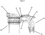
- die Filterkupplung der
Figur 1 in einem am Dialysator angeschlossenen Zustand; und - Figur 3:
- eine Parkstation eines erfindungsgemäßen Dialysegeräts.
- Die Filterkupplungen 10 des in den Figuren dargestellten Beispiels eines erfindungsgemäßen Dialysegeräts sind dazu ausgebildet, manuell mit Anschlüssen 21 eines Dialysators 20 verbunden zu werden. Das Dialysegerät umfasst zwei derartige Filterkupplungen, eine zur Verbindung mit dem Zulaufanschluss des Dialysators und eine zur Verbindung mit dem Rücklaufanschluss des Dialysators.
- Die Filterkupplungen 10 umfassen eine weibliche Aufnahme 11, in die ein männlicher Anschluss 21 eines Dialysators 20 eingesteckt werden kann. Ein Betätigungshebel 12 dient zum Lösen und Festsetzen der Aufnahme 11 am Anschluss 21. An der gegenüberliegenden Seite der Filterkupplungen 10 befindet sich ein Anbindungsbereich 13 für einen Flüssigkeitsschlauch. Zwischen der Aufnahme 11 und dem Anbindungsbereich 13 ist ein Fluidkanal 14 gebildet. Kennzeichnend für die vorliegende Erfindung ist der in der Aufnahme 11 sitzende Konnektionssensor 15, der eine Verbindung der Filterkupplung 10 mit dem Anschluss 21 erkennen kann. Beispielsweise handelt es sich dabei um einen Berührungssensor. Er kann drahtlos oder anhand eines nicht dargestellten Verbindungsdrahtes mit der Steuereinheit des Dialysegeräts in Verbindung stehen.
- An einer Park- bzw. Kurzschlussstation 30 des Dialysegeräts befinden sich Kurzschlussanschlüsse 31a und 31b für beide Filterkupplungen 10a und 10b des Dialysegeräts. Jeder dieser Kurzschlussanschlüsse 31a und 31b ist mit einer separaten Abdeckklappe 32a bzw. 32b überdeckt. Die Abdeckungssensoren 33a und 33b dienen der Erkennung der Stellung der jeweiligen Abdeckklappe 32a bzw. 32b. Das Dialysegerät umfasst ferner nicht näher dargestellte elektromagnetische Riegel zum Sperren der Abdeckklappen 32a und 32b sowie nicht näher dargestellte elektrische Aktoren zum Öffnen und Schließen der Abdeckklappen 32a und 32b. Die Abdeckungssensoren 33a und 33b stehen ebenso wie die Riegel und Aktoren mit der Steuereinheit des Gerätes in Verbindung. Die Steuereinheit steht mit einer Signaleinrichtung in Verbindung, die Warnsignale ausgeben kann.
- Somit sind in einem erfindungsgemäßen Dialysegerät die Filterkupplungen 10 mit je einem Konnektionssensor 15 ausgestattet, welcher die Konnektionsstellung, d.h. die Verbindung mit einem Anschluss eines Dialysators 20 erkennt. Ferner wird die Kurzschlussstation 30 aufgeteilt und jeder Kurzschlussanschluss 31a und 31b mit einer separaten Abdeckklappe 32a bzw. 32b inkl. Abdeckungssensor 33 versehen. Die Kurzschlussanschlüsse 31a und 31b, auf welche die Filterkupplungen 10a bzw. 10b bei Nicht-Betrieb oder während des Reinigungsprogramms deponiert werden, sind also mit je einer eignen mechanischen Abdeckklappe 32a bzw. 32b ausgestattet, welche einzeln überwacht betätigt werden kann.
- Der Abrüstvorgang, also das Trennen des Dialysators 20 von dem Dialysegerät kann folgendermaßen erfolgen: Eine der Filterkupplungen 10 wird vom Anwender einzeln vom zugeordneten Anschluss 21 des Dialysators gelöst. Der Konnektionssensor 15 erkennt, welche der beiden Kupplungen 10 dekonnektiert wurde und gibt den dazugehörigen Kurzschlussanschluss 31 frei bzw. sperrt den nicht dazugehörigen Kurzschlussanschluss 31. Freigabe kann bedeuten, dass (a) eine Verriegelung der Klappe 32 aufgehoben wird, (b) die Klappe 32 automatisch mittels Aktor geöffnet wird, oder (c) kein Warnsignal ausgegeben wird, wenn die Klappe 32 manuell geöffnet wird. Sperrung kann bedeuten, dass (a) die Klappe 32 verriegelt wird, oder (b) ein Warnsignal ausgegeben wird, wenn die Klappe 32 manuell geöffnet wird.
- Der Aufrüstvorgang, also das Verbinden des Dialysators und des Dialysegeräts kann folgendermaßen erfolgen: Eine Klappe 32 wird vom Anwender geöffnet. Der Abdeckungssensor 33 erkennt welche Klappe 32 geöffnet wird und sperrt, im obigen Sinne, die andere Klappe.
Claims (10)
- Dialysegerät mit zwei dialysatseitigen Hydraulikanschlüssen, an denen je eine Verbindungsleitung mit einer Filterkupplung (10) zur Verbindung mit einem Dialysator (20) angebunden ist, wobei es sich bei den Hydraulikanschlüssen um einen Zulaufanschluss zur Zuleitung frischer Dialysierflüssigkeit zum Dialysator (20) und um einen Rücklaufanschluss zur Ableitung verbrauchten Dialysats vom Dialysator (20) handelt, sowie mit zwei den jeweiligen Hydraulikanschlüssen zugeordneten Parkstellen (31a, 31b) zum Lagern der Filterkupplungen (10) bei Nichtbetrieb,dadurch gekennzeichnet, dassbeide Parkstellen (31a, 31b) mit einer separaten Abdeckung (32a, 32b) versehen sind und das Dialysegerät lösbare Verriegelungen zum Sperren der Abdeckungen (32a, 32b) der Parkstellen aufweist.
- Dialysegerät nach Anspruch 1, dadurch gekennzeichnet, dass die Filterkupplungen (10) beider Hydraulikanschlüsse mit einem Konnektionssensor (15) ausgestattet sind, der eine Konnektierung der Filterkupplung (10) an einen Dialysator (20) erkennt.
- Dialysegerät nach einem der vorhergehenden Ansprüche, dadurch gekennzeichnet, dass das Dialysegerät Abdeckungssensoren (33) zur Erkennung der Stellung der Abdeckungen (32a, 32b) der Parkstellen aufweist.
- Dialysegerät nach einem der vorhergehenden Ansprüche, dadurch gekennzeichnet, dass das Dialysegerät Aktoren zum öffnen und Schließen der Abdeckungen (32a, 32b) der Parkstellen aufweist.
- Dialysegerät nach einem der vorhergehenden Ansprüche, dadurch gekennzeichnet, dass das Dialysegerät eine Signaleinheit zur Ausgabe von Warnsignalen aufweist.
- Dialysegerät nach einem der vorhergehenden Ansprüche, zumindest jedoch fortgebildet mit den Merkmalen des Anspruchs 2, dadurch gekennzeichnet, dass das Dialysegerät eine Steuereinheit aufweist, die mit den Konnektionssensoren (15) und vorzugsweise ferner mit den Verriegelungen, Abdeckungssensoren (33) und/oder Aktoren in Verbindung steht.
- Dialysegerät nach Anspruch 6 und fortgebildet mit den Merkmalen des Anspruchs 1, dadurch gekennzeichnet, dass die Steuereinheit so ausgebildet ist, dass bei Erkennung der Dekonnektierung einer Filterkupplung (10) vom Dialysator (20) die dem betreffenden Hydraulikanschluss zugeordnete Parkstelle (31a, 31b) freigegeben wird oder bleibt und/oder die dem betreffenden Hydraulikanschluss nicht zugeordnete Parkstelle (31a, 31b) gesperrt wird oder bleibt.
- Dialysegerät nach Ansprüchen 2, 1, 3 und 6, dadurch gekennzeichnet, dass die Steuereinheit so ausgebildet ist, dass bei Erkennung einer Öffnung der Abdeckung (32a, 32b) einer Parkstelle (31a, 31b) die Verriegelung der Abdeckung (32a, 32b) der anderen Parkstelle (31a, 31b) gesperrt wird, bis eine Konnektierung derjenigen Filterkupplung (10) an einen Dialysator (20) erkannt wird, deren zugehörige Parkstelle (31a, 31b) durch Öffnen der Abdeckung (32a, 32b) freigegeben wurde.
- Verfahren zur Trennung eines Dialysators (20) von einem Dialysegerät nach einem der vorhergehenden Ansprüche, zumindest jedoch fortgebildet mit den Merkmalen des Anspruchs 2,dadurch gekennzeichnet,dass bei Erkennung der Dekonnektierung einer Filterkupplung (10) vom Dialysator (20) die dem betreffenden Hydraulikanschluss zugeordnete Parkstelle (31a, 31b) freigegeben wird oder bleibt und/oder die dem betreffenden Hydraulikanschluss nicht zugeordnete Parkstelle (31a, 31b) gesperrt wird oder bleibt.
- Verfahren zur Verbindung eines Dialysators (20) mit einem Dialysegerät nach Ansprüchen 2, 1, 3 und 6,dadurch gekennzeichnet,dass bei Erkennung einer Öffnung der Abdeckung (32a, 32b) einer Parkstelle (31a, 31b) die Verriegelung der Abdeckung (32a, 32b) der anderen Parkstelle (31a, 31b) gesperrt wird, bis eine Konnektierung derjenigen Filterkupplung (10) an einen Dialysator (20) erkannt wird, deren zugehörige Parkstelle (31a, 31b) durch Öffnen der Abdeckung (32a, 32b) freigegeben wurde.
Applications Claiming Priority (2)
| Application Number | Priority Date | Filing Date | Title |
|---|---|---|---|
| DE102017128080.4A DE102017128080A1 (de) | 2017-11-28 | 2017-11-28 | Dialysegerät mit Verwechslungssicherung für Hydraulikanschlüsse |
| PCT/EP2018/082887 WO2019106039A1 (de) | 2017-11-28 | 2018-11-28 | Dialysegerät mit verwechslungssicherung für hydraulikanschlüsse |
Publications (2)
| Publication Number | Publication Date |
|---|---|
| EP3717039A1 EP3717039A1 (de) | 2020-10-07 |
| EP3717039B1 true EP3717039B1 (de) | 2021-11-10 |
Family
ID=64650361
Family Applications (1)
| Application Number | Title | Priority Date | Filing Date |
|---|---|---|---|
| EP18815128.6A Active EP3717039B1 (de) | 2017-11-28 | 2018-11-28 | Dialysegerät mit verwechslungssicherung für hydraulikanschlüsse |
Country Status (5)
| Country | Link |
|---|---|
| US (1) | US12144913B2 (de) |
| EP (1) | EP3717039B1 (de) |
| CN (1) | CN111405917B (de) |
| DE (1) | DE102017128080A1 (de) |
| WO (1) | WO2019106039A1 (de) |
Families Citing this family (2)
| Publication number | Priority date | Publication date | Assignee | Title |
|---|---|---|---|---|
| DE102020133387A1 (de) | 2020-12-14 | 2022-06-15 | Fresenius Medical Care Deutschland Gmbh | Kurzschlussleitung, medizintechnische Behandlungsvorrichtung, sowie Verfahren |
| EP4180067B1 (de) | 2021-11-10 | 2024-01-03 | Kai-Uwe Ritter | Vorrichtung zur extrakorporalen blutbehandlung |
Family Cites Families (9)
| Publication number | Priority date | Publication date | Assignee | Title |
|---|---|---|---|---|
| DE4303372A1 (de) * | 1993-02-05 | 1994-08-11 | Fresenius Ag | Beutel zur Aufnahme von Konzentrat |
| US5589070A (en) | 1993-07-16 | 1996-12-31 | Cobe Laboratories, Inc. | Method and apparatus for cleaning a dialysate circuit downstream of a dialyzer |
| ES2256348T3 (es) * | 2002-03-11 | 2006-07-16 | Fresenius Medical Care Deutschland Gmbh | Conector, contenedor con tal conector y dispositivo de preparacion de fluido con conector de acoplamiento para tal contenedor. |
| DE102007009269B4 (de) * | 2007-02-26 | 2010-11-11 | Fresenius Medical Care Deutschland Gmbh | Vorrichtung und Verfahren zum Befüllen und/oder Entleeren eines Dialysegerätes |
| EP3037117B1 (de) * | 2007-10-12 | 2017-12-20 | DEKA Products Limited Partnership | Blutschlauchverbinder |
| DE102013103336A1 (de) * | 2013-04-03 | 2014-10-09 | B. Braun Avitum Ag | Vorrichtung zur Identifizierung einer Dialysatorvorrichtung oder einer Komponente derselben, und hierfür verwendbare Sensorvorrichtung |
| DE102013112038A1 (de) * | 2013-10-31 | 2015-04-30 | Fresenius Medical Care AG & Co. KGaA | Blutbehandlungsvorrichtung mit erhöhter Patientensicherheit und Verfahren |
| DE102015102719A1 (de) * | 2015-02-25 | 2016-08-25 | B. Braun Avitum Ag | Konnektor für einen Dialysator |
| DE102015122347A1 (de) * | 2015-12-21 | 2017-06-22 | Fresenius Medical Care Deutschland Gmbh | Sensorgesteuerte Displayausgabe für Dialysemaschinen |
-
2017
- 2017-11-28 DE DE102017128080.4A patent/DE102017128080A1/de not_active Withdrawn
-
2018
- 2018-11-28 US US16/767,177 patent/US12144913B2/en active Active
- 2018-11-28 WO PCT/EP2018/082887 patent/WO2019106039A1/de not_active Ceased
- 2018-11-28 CN CN201880076374.8A patent/CN111405917B/zh active Active
- 2018-11-28 EP EP18815128.6A patent/EP3717039B1/de active Active
Also Published As
| Publication number | Publication date |
|---|---|
| DE102017128080A1 (de) | 2019-05-29 |
| US12144913B2 (en) | 2024-11-19 |
| CN111405917B (zh) | 2023-11-03 |
| WO2019106039A1 (de) | 2019-06-06 |
| US20200384175A1 (en) | 2020-12-10 |
| CN111405917A (zh) | 2020-07-10 |
| EP3717039A1 (de) | 2020-10-07 |
Similar Documents
| Publication | Publication Date | Title |
|---|---|---|
| EP3439518B1 (de) | Milchzufuhrvorrichtung sowie verfahren zum zuführen von milch | |
| EP2547415B1 (de) | Filtereinrichtung | |
| EP0622086B1 (de) | Hydraulische Sicherheitsschaltung für einen Hämodialyse-Apparat | |
| EP2836247B1 (de) | Rezirkulationsvorrichtung eines extrakorporalen blutbehandlungsgeräts | |
| EP2453973B2 (de) | Verbindungsvorrichtung zum zusammenführen wenigstens zweier leitungsabschnitte bei einem unterdruckwundbehandlungssystem | |
| DE102012005187B4 (de) | Medizinische Vorrichtung mit einer Buchsen-Einheit zum Anschluss einer Vorrichtung zur Bereitstellung von medizinischen Flüssigkeiten | |
| EP0198407A2 (de) | Konnektor für Peritonealdialyse | |
| EP2825248A1 (de) | Medizinische vorrichtung mit einer buchsen-einheit zum anschluss einer vorrichtung zur bereitstellung von medizinischen flüssigkeiten | |
| EP2825249B1 (de) | Medizinische behandlungsvorrichtung und vorrichtung zur bereitstellung von medizinischen behandlungsflüssigkeiten sowie vorrichtung zum befüllen einer vorrichtung zur bereitstellung von medizinischen flüssigkeiten | |
| DE102018104457A1 (de) | Anschlusseinheit für eine Blutbehandlungsmaschine zum Anschließen der Blutbehandlungsmaschine an einen externen Behälter und Blutbehandlungsmaschine mit einer derartigen Anschlusseinheit | |
| WO2012095343A2 (de) | Saugleitung für eine unterdruckwundbehandlungseinrichtung mit steckverbinderteilen | |
| WO2017153223A1 (de) | Hydraulische lenkeinrichtung mit erweiterter fehlervermeidung | |
| EP3717039A1 (de) | Dialysegerät mit verwechslungssicherung für hydraulikanschlüsse | |
| DE202013101695U1 (de) | Rezirkulationsvorrichtung eines extrakorporalen Blutbehandlungsgeräts | |
| EP3403708B1 (de) | Filtersystem mit zentralelement und siebfilter | |
| EP3117847B1 (de) | Extrakorporale blutbehandlungsanlage mit integriertem desinfektionsbehälter | |
| EP3669718B1 (de) | Wassertankeinrichtung und getränkeautomat | |
| DE102013107323A1 (de) | Extrakorporale Blutbehandlungsmaschine mit Potentialausgleichsvorrichtung | |
| DE202019104978U1 (de) | Blutseparationsvorrichtung | |
| EP3717038B1 (de) | Dialysegerät mit verwechslungssicherung für hydraulikanschlüsse | |
| DE102014209817A1 (de) | Schlaucheinrichtung zum Transportieren von Fluiden für ein Haushaltsgerät, Vorrichtung, Haushaltsgerät sowie Verfahren | |
| DE102015015422B4 (de) | Aufnahmevorrichtung für mindestens eine Analysemembran | |
| DE102017003579A1 (de) | Vorrichtung zum Austauschen eines Filterelements | |
| DE2023491C (de) | Filtervorrichtung | |
| DE202016100941U1 (de) | Einrichtung zum Ableiten von Flüssigkeiten und Fetten aus Ofen-Garkammern, insbesondere für Lebensmittelöfen |
Legal Events
| Date | Code | Title | Description |
|---|---|---|---|
| STAA | Information on the status of an ep patent application or granted ep patent |
Free format text: STATUS: UNKNOWN |
|
| STAA | Information on the status of an ep patent application or granted ep patent |
Free format text: STATUS: THE INTERNATIONAL PUBLICATION HAS BEEN MADE |
|
| PUAI | Public reference made under article 153(3) epc to a published international application that has entered the european phase |
Free format text: ORIGINAL CODE: 0009012 |
|
| STAA | Information on the status of an ep patent application or granted ep patent |
Free format text: STATUS: REQUEST FOR EXAMINATION WAS MADE |
|
| 17P | Request for examination filed |
Effective date: 20200617 |
|
| AK | Designated contracting states |
Kind code of ref document: A1 Designated state(s): AL AT BE BG CH CY CZ DE DK EE ES FI FR GB GR HR HU IE IS IT LI LT LU LV MC MK MT NL NO PL PT RO RS SE SI SK SM TR |
|
| AX | Request for extension of the european patent |
Extension state: BA ME |
|
| DAV | Request for validation of the european patent (deleted) | ||
| DAX | Request for extension of the european patent (deleted) | ||
| GRAP | Despatch of communication of intention to grant a patent |
Free format text: ORIGINAL CODE: EPIDOSNIGR1 |
|
| STAA | Information on the status of an ep patent application or granted ep patent |
Free format text: STATUS: GRANT OF PATENT IS INTENDED |
|
| RIN1 | Information on inventor provided before grant (corrected) |
Inventor name: HAECKER, JUERGEN Inventor name: SCHEUNERT, PETER Inventor name: BOND, OLIVER Inventor name: BREHM, WINFRIED Inventor name: KALSER, MARTIN |
|
| INTG | Intention to grant announced |
Effective date: 20210607 |
|
| GRAS | Grant fee paid |
Free format text: ORIGINAL CODE: EPIDOSNIGR3 |
|
| GRAA | (expected) grant |
Free format text: ORIGINAL CODE: 0009210 |
|
| STAA | Information on the status of an ep patent application or granted ep patent |
Free format text: STATUS: THE PATENT HAS BEEN GRANTED |
|
| AK | Designated contracting states |
Kind code of ref document: B1 Designated state(s): AL AT BE BG CH CY CZ DE DK EE ES FI FR GB GR HR HU IE IS IT LI LT LU LV MC MK MT NL NO PL PT RO RS SE SI SK SM TR |
|
| REG | Reference to a national code |
Ref country code: GB Ref legal event code: FG4D Free format text: NOT ENGLISH |
|
| REG | Reference to a national code |
Ref country code: AT Ref legal event code: REF Ref document number: 1445466 Country of ref document: AT Kind code of ref document: T Effective date: 20211115 Ref country code: CH Ref legal event code: EP |
|
| REG | Reference to a national code |
Ref country code: DE Ref legal event code: R096 Ref document number: 502018007823 Country of ref document: DE |
|
| REG | Reference to a national code |
Ref country code: IE Ref legal event code: FG4D Free format text: LANGUAGE OF EP DOCUMENT: GERMAN |
|
| REG | Reference to a national code |
Ref country code: LT Ref legal event code: MG9D |
|
| REG | Reference to a national code |
Ref country code: NL Ref legal event code: MP Effective date: 20211110 |
|
| PG25 | Lapsed in a contracting state [announced via postgrant information from national office to epo] |
Ref country code: RS Free format text: LAPSE BECAUSE OF FAILURE TO SUBMIT A TRANSLATION OF THE DESCRIPTION OR TO PAY THE FEE WITHIN THE PRESCRIBED TIME-LIMIT Effective date: 20211110 Ref country code: LT Free format text: LAPSE BECAUSE OF FAILURE TO SUBMIT A TRANSLATION OF THE DESCRIPTION OR TO PAY THE FEE WITHIN THE PRESCRIBED TIME-LIMIT Effective date: 20211110 Ref country code: FI Free format text: LAPSE BECAUSE OF FAILURE TO SUBMIT A TRANSLATION OF THE DESCRIPTION OR TO PAY THE FEE WITHIN THE PRESCRIBED TIME-LIMIT Effective date: 20211110 Ref country code: BG Free format text: LAPSE BECAUSE OF FAILURE TO SUBMIT A TRANSLATION OF THE DESCRIPTION OR TO PAY THE FEE WITHIN THE PRESCRIBED TIME-LIMIT Effective date: 20220210 |
|
| PG25 | Lapsed in a contracting state [announced via postgrant information from national office to epo] |
Ref country code: IS Free format text: LAPSE BECAUSE OF FAILURE TO SUBMIT A TRANSLATION OF THE DESCRIPTION OR TO PAY THE FEE WITHIN THE PRESCRIBED TIME-LIMIT Effective date: 20220310 Ref country code: SE Free format text: LAPSE BECAUSE OF FAILURE TO SUBMIT A TRANSLATION OF THE DESCRIPTION OR TO PAY THE FEE WITHIN THE PRESCRIBED TIME-LIMIT Effective date: 20211110 Ref country code: PT Free format text: LAPSE BECAUSE OF FAILURE TO SUBMIT A TRANSLATION OF THE DESCRIPTION OR TO PAY THE FEE WITHIN THE PRESCRIBED TIME-LIMIT Effective date: 20220310 Ref country code: PL Free format text: LAPSE BECAUSE OF FAILURE TO SUBMIT A TRANSLATION OF THE DESCRIPTION OR TO PAY THE FEE WITHIN THE PRESCRIBED TIME-LIMIT Effective date: 20211110 Ref country code: NO Free format text: LAPSE BECAUSE OF FAILURE TO SUBMIT A TRANSLATION OF THE DESCRIPTION OR TO PAY THE FEE WITHIN THE PRESCRIBED TIME-LIMIT Effective date: 20220210 Ref country code: NL Free format text: LAPSE BECAUSE OF FAILURE TO SUBMIT A TRANSLATION OF THE DESCRIPTION OR TO PAY THE FEE WITHIN THE PRESCRIBED TIME-LIMIT Effective date: 20211110 Ref country code: LV Free format text: LAPSE BECAUSE OF FAILURE TO SUBMIT A TRANSLATION OF THE DESCRIPTION OR TO PAY THE FEE WITHIN THE PRESCRIBED TIME-LIMIT Effective date: 20211110 Ref country code: HR Free format text: LAPSE BECAUSE OF FAILURE TO SUBMIT A TRANSLATION OF THE DESCRIPTION OR TO PAY THE FEE WITHIN THE PRESCRIBED TIME-LIMIT Effective date: 20211110 Ref country code: GR Free format text: LAPSE BECAUSE OF FAILURE TO SUBMIT A TRANSLATION OF THE DESCRIPTION OR TO PAY THE FEE WITHIN THE PRESCRIBED TIME-LIMIT Effective date: 20220211 |
|
| REG | Reference to a national code |
Ref country code: CH Ref legal event code: PL |
|
| PG25 | Lapsed in a contracting state [announced via postgrant information from national office to epo] |
Ref country code: SM Free format text: LAPSE BECAUSE OF FAILURE TO SUBMIT A TRANSLATION OF THE DESCRIPTION OR TO PAY THE FEE WITHIN THE PRESCRIBED TIME-LIMIT Effective date: 20211110 Ref country code: SK Free format text: LAPSE BECAUSE OF FAILURE TO SUBMIT A TRANSLATION OF THE DESCRIPTION OR TO PAY THE FEE WITHIN THE PRESCRIBED TIME-LIMIT Effective date: 20211110 Ref country code: RO Free format text: LAPSE BECAUSE OF FAILURE TO SUBMIT A TRANSLATION OF THE DESCRIPTION OR TO PAY THE FEE WITHIN THE PRESCRIBED TIME-LIMIT Effective date: 20211110 Ref country code: LU Free format text: LAPSE BECAUSE OF NON-PAYMENT OF DUE FEES Effective date: 20211128 Ref country code: ES Free format text: LAPSE BECAUSE OF FAILURE TO SUBMIT A TRANSLATION OF THE DESCRIPTION OR TO PAY THE FEE WITHIN THE PRESCRIBED TIME-LIMIT Effective date: 20211110 Ref country code: EE Free format text: LAPSE BECAUSE OF FAILURE TO SUBMIT A TRANSLATION OF THE DESCRIPTION OR TO PAY THE FEE WITHIN THE PRESCRIBED TIME-LIMIT Effective date: 20211110 Ref country code: DK Free format text: LAPSE BECAUSE OF FAILURE TO SUBMIT A TRANSLATION OF THE DESCRIPTION OR TO PAY THE FEE WITHIN THE PRESCRIBED TIME-LIMIT Effective date: 20211110 Ref country code: CZ Free format text: LAPSE BECAUSE OF FAILURE TO SUBMIT A TRANSLATION OF THE DESCRIPTION OR TO PAY THE FEE WITHIN THE PRESCRIBED TIME-LIMIT Effective date: 20211110 Ref country code: BE Free format text: LAPSE BECAUSE OF NON-PAYMENT OF DUE FEES Effective date: 20211130 |
|
| REG | Reference to a national code |
Ref country code: BE Ref legal event code: MM Effective date: 20211130 |
|
| REG | Reference to a national code |
Ref country code: DE Ref legal event code: R097 Ref document number: 502018007823 Country of ref document: DE |
|
| PG25 | Lapsed in a contracting state [announced via postgrant information from national office to epo] |
Ref country code: MC Free format text: LAPSE BECAUSE OF FAILURE TO SUBMIT A TRANSLATION OF THE DESCRIPTION OR TO PAY THE FEE WITHIN THE PRESCRIBED TIME-LIMIT Effective date: 20211110 Ref country code: LI Free format text: LAPSE BECAUSE OF NON-PAYMENT OF DUE FEES Effective date: 20211130 Ref country code: CH Free format text: LAPSE BECAUSE OF NON-PAYMENT OF DUE FEES Effective date: 20211130 |
|
| PLBE | No opposition filed within time limit |
Free format text: ORIGINAL CODE: 0009261 |
|
| STAA | Information on the status of an ep patent application or granted ep patent |
Free format text: STATUS: NO OPPOSITION FILED WITHIN TIME LIMIT |
|
| 26N | No opposition filed |
Effective date: 20220811 |
|
| PG25 | Lapsed in a contracting state [announced via postgrant information from national office to epo] |
Ref country code: IE Free format text: LAPSE BECAUSE OF NON-PAYMENT OF DUE FEES Effective date: 20211128 Ref country code: AL Free format text: LAPSE BECAUSE OF FAILURE TO SUBMIT A TRANSLATION OF THE DESCRIPTION OR TO PAY THE FEE WITHIN THE PRESCRIBED TIME-LIMIT Effective date: 20211110 |
|
| PG25 | Lapsed in a contracting state [announced via postgrant information from national office to epo] |
Ref country code: SI Free format text: LAPSE BECAUSE OF FAILURE TO SUBMIT A TRANSLATION OF THE DESCRIPTION OR TO PAY THE FEE WITHIN THE PRESCRIBED TIME-LIMIT Effective date: 20211110 |
|
| PG25 | Lapsed in a contracting state [announced via postgrant information from national office to epo] |
Ref country code: CY Free format text: LAPSE BECAUSE OF FAILURE TO SUBMIT A TRANSLATION OF THE DESCRIPTION OR TO PAY THE FEE WITHIN THE PRESCRIBED TIME-LIMIT Effective date: 20211110 |
|
| P01 | Opt-out of the competence of the unified patent court (upc) registered |
Effective date: 20230602 |
|
| GBPC | Gb: european patent ceased through non-payment of renewal fee |
Effective date: 20221128 |
|
| PG25 | Lapsed in a contracting state [announced via postgrant information from national office to epo] |
Ref country code: HU Free format text: LAPSE BECAUSE OF FAILURE TO SUBMIT A TRANSLATION OF THE DESCRIPTION OR TO PAY THE FEE WITHIN THE PRESCRIBED TIME-LIMIT; INVALID AB INITIO Effective date: 20181128 |
|
| PG25 | Lapsed in a contracting state [announced via postgrant information from national office to epo] |
Ref country code: GB Free format text: LAPSE BECAUSE OF NON-PAYMENT OF DUE FEES Effective date: 20221128 |
|
| PG25 | Lapsed in a contracting state [announced via postgrant information from national office to epo] |
Ref country code: MK Free format text: LAPSE BECAUSE OF FAILURE TO SUBMIT A TRANSLATION OF THE DESCRIPTION OR TO PAY THE FEE WITHIN THE PRESCRIBED TIME-LIMIT Effective date: 20211110 |
|
| PG25 | Lapsed in a contracting state [announced via postgrant information from national office to epo] |
Ref country code: TR Free format text: LAPSE BECAUSE OF FAILURE TO SUBMIT A TRANSLATION OF THE DESCRIPTION OR TO PAY THE FEE WITHIN THE PRESCRIBED TIME-LIMIT Effective date: 20211110 |
|
| PG25 | Lapsed in a contracting state [announced via postgrant information from national office to epo] |
Ref country code: MT Free format text: LAPSE BECAUSE OF FAILURE TO SUBMIT A TRANSLATION OF THE DESCRIPTION OR TO PAY THE FEE WITHIN THE PRESCRIBED TIME-LIMIT Effective date: 20211110 |
|
| REG | Reference to a national code |
Ref country code: AT Ref legal event code: MM01 Ref document number: 1445466 Country of ref document: AT Kind code of ref document: T Effective date: 20231128 |
|
| PG25 | Lapsed in a contracting state [announced via postgrant information from national office to epo] |
Ref country code: AT Free format text: LAPSE BECAUSE OF NON-PAYMENT OF DUE FEES Effective date: 20231128 |
|
| PG25 | Lapsed in a contracting state [announced via postgrant information from national office to epo] |
Ref country code: AT Free format text: LAPSE BECAUSE OF NON-PAYMENT OF DUE FEES Effective date: 20231128 |
|
| PGFP | Annual fee paid to national office [announced via postgrant information from national office to epo] |
Ref country code: DE Payment date: 20251022 Year of fee payment: 8 |
|
| PGFP | Annual fee paid to national office [announced via postgrant information from national office to epo] |
Ref country code: IT Payment date: 20251022 Year of fee payment: 8 |
|
| PGFP | Annual fee paid to national office [announced via postgrant information from national office to epo] |
Ref country code: FR Payment date: 20251022 Year of fee payment: 8 |
|
| PGFP | Annual fee paid to national office [announced via postgrant information from national office to epo] |
Ref country code: AT Payment date: 20260410 Year of fee payment: 5 |