EP3716708A1 - Data transmission method and apparatus, and computer storage medium - Google Patents
Data transmission method and apparatus, and computer storage medium Download PDFInfo
- Publication number
- EP3716708A1 EP3716708A1 EP18882179.7A EP18882179A EP3716708A1 EP 3716708 A1 EP3716708 A1 EP 3716708A1 EP 18882179 A EP18882179 A EP 18882179A EP 3716708 A1 EP3716708 A1 EP 3716708A1
- Authority
- EP
- European Patent Office
- Prior art keywords
- dmrs
- ordering
- dmrs port
- qcl
- group
- Prior art date
- Legal status (The legal status is an assumption and is not a legal conclusion. Google has not performed a legal analysis and makes no representation as to the accuracy of the status listed.)
- Granted
Links
Images


Classifications
-
- H—ELECTRICITY
- H04—ELECTRIC COMMUNICATION TECHNIQUE
- H04L—TRANSMISSION OF DIGITAL INFORMATION, e.g. TELEGRAPHIC COMMUNICATION
- H04L5/00—Arrangements affording multiple use of the transmission path
- H04L5/02—Channels characterised by the type of signal
- H04L5/06—Channels characterised by the type of signal the signals being represented by different frequencies
- H04L5/10—Channels characterised by the type of signal the signals being represented by different frequencies with dynamo-electric generation of carriers; with mechanical filters or demodulators
-
- H—ELECTRICITY
- H04—ELECTRIC COMMUNICATION TECHNIQUE
- H04L—TRANSMISSION OF DIGITAL INFORMATION, e.g. TELEGRAPHIC COMMUNICATION
- H04L5/00—Arrangements affording multiple use of the transmission path
- H04L5/003—Arrangements for allocating sub-channels of the transmission path
- H04L5/0048—Allocation of pilot signals, i.e. of signals known to the receiver
- H04L5/0051—Allocation of pilot signals, i.e. of signals known to the receiver of dedicated pilots, i.e. pilots destined for a single user or terminal
-
- H—ELECTRICITY
- H04—ELECTRIC COMMUNICATION TECHNIQUE
- H04B—TRANSMISSION
- H04B17/00—Monitoring; Testing
- H04B17/30—Monitoring; Testing of propagation channels
- H04B17/373—Predicting channel quality or other radio frequency [RF] parameters
-
- H—ELECTRICITY
- H04—ELECTRIC COMMUNICATION TECHNIQUE
- H04B—TRANSMISSION
- H04B7/00—Radio transmission systems, i.e. using radiation field
- H04B7/02—Diversity systems; Multi-antenna system, i.e. transmission or reception using multiple antennas
- H04B7/04—Diversity systems; Multi-antenna system, i.e. transmission or reception using multiple antennas using two or more spaced independent antennas
- H04B7/0413—MIMO systems
-
- H—ELECTRICITY
- H04—ELECTRIC COMMUNICATION TECHNIQUE
- H04B—TRANSMISSION
- H04B7/00—Radio transmission systems, i.e. using radiation field
- H04B7/02—Diversity systems; Multi-antenna system, i.e. transmission or reception using multiple antennas
- H04B7/04—Diversity systems; Multi-antenna system, i.e. transmission or reception using multiple antennas using two or more spaced independent antennas
- H04B7/06—Diversity systems; Multi-antenna system, i.e. transmission or reception using multiple antennas using two or more spaced independent antennas at the transmitting station
- H04B7/0613—Diversity systems; Multi-antenna system, i.e. transmission or reception using multiple antennas using two or more spaced independent antennas at the transmitting station using simultaneous transmission
- H04B7/0615—Diversity systems; Multi-antenna system, i.e. transmission or reception using multiple antennas using two or more spaced independent antennas at the transmitting station using simultaneous transmission of weighted versions of same signal
- H04B7/0619—Diversity systems; Multi-antenna system, i.e. transmission or reception using multiple antennas using two or more spaced independent antennas at the transmitting station using simultaneous transmission of weighted versions of same signal using feedback from receiving side
- H04B7/0621—Feedback content
- H04B7/0634—Antenna weights or vector/matrix coefficients
-
- H—ELECTRICITY
- H04—ELECTRIC COMMUNICATION TECHNIQUE
- H04B—TRANSMISSION
- H04B7/00—Radio transmission systems, i.e. using radiation field
- H04B7/02—Diversity systems; Multi-antenna system, i.e. transmission or reception using multiple antennas
- H04B7/04—Diversity systems; Multi-antenna system, i.e. transmission or reception using multiple antennas using two or more spaced independent antennas
- H04B7/06—Diversity systems; Multi-antenna system, i.e. transmission or reception using multiple antennas using two or more spaced independent antennas at the transmitting station
- H04B7/0686—Hybrid systems, i.e. switching and simultaneous transmission
- H04B7/0695—Hybrid systems, i.e. switching and simultaneous transmission using beam selection
- H04B7/06952—Selecting one or more beams from a plurality of beams, e.g. beam training, management or sweeping
- H04B7/06968—Selecting one or more beams from a plurality of beams, e.g. beam training, management or sweeping using quasi-colocation [QCL] between signals
-
- H—ELECTRICITY
- H04—ELECTRIC COMMUNICATION TECHNIQUE
- H04L—TRANSMISSION OF DIGITAL INFORMATION, e.g. TELEGRAPHIC COMMUNICATION
- H04L5/00—Arrangements affording multiple use of the transmission path
- H04L5/0091—Signalling for the administration of the divided path, e.g. signalling of configuration information
-
- H—ELECTRICITY
- H04—ELECTRIC COMMUNICATION TECHNIQUE
- H04W—WIRELESS COMMUNICATION NETWORKS
- H04W72/00—Local resource management
- H04W72/12—Wireless traffic scheduling
- H04W72/1263—Mapping of traffic onto schedule, e.g. scheduled allocation or multiplexing of flows
-
- H—ELECTRICITY
- H04—ELECTRIC COMMUNICATION TECHNIQUE
- H04W—WIRELESS COMMUNICATION NETWORKS
- H04W72/00—Local resource management
- H04W72/20—Control channels or signalling for resource management
- H04W72/23—Control channels or signalling for resource management in the downlink direction of a wireless link, i.e. towards a terminal
-
- H—ELECTRICITY
- H04—ELECTRIC COMMUNICATION TECHNIQUE
- H04W—WIRELESS COMMUNICATION NETWORKS
- H04W72/00—Local resource management
- H04W72/20—Control channels or signalling for resource management
- H04W72/23—Control channels or signalling for resource management in the downlink direction of a wireless link, i.e. towards a terminal
- H04W72/231—Control channels or signalling for resource management in the downlink direction of a wireless link, i.e. towards a terminal the control data signalling from the layers above the physical layer, e.g. RRC or MAC-CE signalling
-
- H—ELECTRICITY
- H04—ELECTRIC COMMUNICATION TECHNIQUE
- H04W—WIRELESS COMMUNICATION NETWORKS
- H04W72/00—Local resource management
- H04W72/20—Control channels or signalling for resource management
- H04W72/23—Control channels or signalling for resource management in the downlink direction of a wireless link, i.e. towards a terminal
- H04W72/232—Control channels or signalling for resource management in the downlink direction of a wireless link, i.e. towards a terminal the control data signalling from the physical layer, e.g. DCI signalling
-
- H—ELECTRICITY
- H04—ELECTRIC COMMUNICATION TECHNIQUE
- H04W—WIRELESS COMMUNICATION NETWORKS
- H04W76/00—Connection management
- H04W76/20—Manipulation of established connections
- H04W76/27—Transitions between radio resource control [RRC] states
-
- H—ELECTRICITY
- H04—ELECTRIC COMMUNICATION TECHNIQUE
- H04W—WIRELESS COMMUNICATION NETWORKS
- H04W80/00—Wireless network protocols or protocol adaptations to wireless operation
- H04W80/02—Data link layer protocols
-
- H—ELECTRICITY
- H04—ELECTRIC COMMUNICATION TECHNIQUE
- H04L—TRANSMISSION OF DIGITAL INFORMATION, e.g. TELEGRAPHIC COMMUNICATION
- H04L5/00—Arrangements affording multiple use of the transmission path
- H04L5/0001—Arrangements for dividing the transmission path
- H04L5/0014—Three-dimensional division
- H04L5/0023—Time-frequency-space
Definitions
- the present application relates to the field of communication technologies, and in particular, to a data transmission method and apparatus, and a computer storage medium.
- a data demodulation process requires channel estimation based on a demodulation reference signal (DMRS).
- DMRS demodulation reference signal
- the DMRS in the NR system is transmitted in the same precoding manner as a corresponding data layer.
- Embodiments of the present application provide a data transmission method and apparatus and a computer storage medium, so as to map a data layer to a DMRS port used in transmission according to a preset DMRS port ordering rule, and perform transmission.
- a data sending method includes: determining a preset DMRS port ordering rule; and mapping one or more data layers to one or more DMRS ports used in transmission according to the preset DMRS port ordering rule, and sending the one or more data layers to a terminal.
- a preset DMRS port ordering rule is determined; and a data layer is mapped to a DMRS port used in transmission according to the preset DMRS port ordering rule, and the data layer is sent to a terminal, so as to map a data layer to a DMRS port used in transmission according to a preset DMRS port ordering rule, and perform transmission.
- mapping the one or more data layers to the one or more DMRS ports used in transmission according to the preset DMRS port ordering rule, and sending the one or more data layers to the terminal specifically includes:
- the method further includes: determining QCL (Quasi-Co-Location) group information of the one or more DMRS ports; and notifying the terminal of the QCL group information.
- QCL Quality of Service
- the signal vector formed by the v DMRS ports is determined according to an ordering result of the serial numbers of the v DMRS ports.
- the ordering result is obtained by: ordering, within each subset, the serial numbers of DMRS ports in the DMRS port subset to obtain an ordering result, within each subset, of the DMRS port serial numbers corresponding to the DMRS port subset; and performing ordering between DMRS port subsets based on the ordering result, within each subset, of the DMRS port serial numbers corresponding to the DMRS port subset, where each DMRS port subset is a set formed by DMRS ports included in a CDM group or QCL group.
- ordering between DMRS port subsets is performed by: performing ordering between DMRS port subsets based on the smallest DMRS port serial number in each DMRS port subset; or performing ordering between DMRS port subsets based on a serial number of the CDM group or QCL group corresponding to each DMRS port subset; or performing ordering between DMRS port subsets based on the number of DMRS ports included in each DMRS port subset.
- the QCL group information specifically includes one of the following information: in a DMRS pattern, an identifier corresponding to a reference signal having a QCL relationship with each CDM group, where DMRS ports included in a CDM group having the same identifier form a same QCL group, and the identifiers corresponding to DMRS ports of different QCL groups are different, and the identifiers corresponding to DMRS ports of a same QCL group are same; a CDM group included in a QCL group; and a list of DMRS ports included in a QCL group.
- the QCL group information of the one or more DMRS ports is notified to the terminal in a broadcast, multicast or terminal-specific manner, through RRC (Radio Resource Control) configuration or a MAC (Media Access Control) CE (Control Element) or DCI (Downlink Control Information).
- RRC Radio Resource Control
- MAC Media Access Control
- DCI Downlink Control Information
- a data receiving method provided in an embodiment of the present application includes: determining a preset DMRS port ordering rule; and receiving one or more sent data layers mapped to one or more DMRS ports according to the preset DMRS port ordering rule.
- receiving one or more sent data layer mapped to one or more DMRS ports according to the preset DMRS port ordering rule specifically includes:
- the method further includes: receiving QCL group information of the one or more DMRS ports notified by the network side.
- the signal vector formed by the v DMRS ports is determined according to an ordering result of the serial numbers of the v DMRS ports.
- the ordering result is obtained by: ordering, within each subset, the serial numbers of DMRS ports in the DMRS port subset to obtain an ordering result, within each subset, of the DMRS port serial numbers corresponding to the DMRS port subset; and performing ordering between DMRS port subsets based on the ordering result, within each subset, of the DMRS port serial numbers corresponding to the DMRS port subset, where each DMRS port subset is a set formed by DMRS ports included in a CDM group or QCL group.
- ordering between DMRS port subsets is performed by: performing ordering between DMRS port subsets based on the smallest DMRS port serial number in each DMRS port subset; or performing ordering between DMRS port subsets based on a serial number of the CDM group or QCL group corresponding to each DMRS port subset; or performing ordering between DMRS port subsets based on the number of DMRS ports included in each DMRS port subset.
- the QCL group information specifically includes one of the following information: in a DMRS pattern, an identifier corresponding to a reference signal having a QCL relationship with each CDM group, where DMRS ports included in a CDM group having the same identifier form a same QCL group, and the identifiers corresponding to DMRS ports of different QCL groups are different, and the identifiers corresponding to DMRS ports of a same QCL group are same; a CDM group included in a QCL group; and a list of DMRS ports included in a QCL group.
- the notification is received in a broadcast, multicast, or terminal-specific manner, and the QCL group information of the one or more DMRS ports is acquired from RRC configuration or an MAC CE or DCI in the notification.
- a data transmission apparatus includes a memory and a processor, where the memory is configured to store program instructions, and the processor is configured to call the program instructions stored in the memory, and execute the following steps according to obtained programs: determining a preset DMRS port ordering rule; and mapping one or more data layers to one or more DMRS ports used in transmission according to the preset DMRS port ordering rule, and sending the one or more data layers to a terminal.
- the processor mapping the one or more data layers to the one or more DMRS ports used in transmission according to the preset DMRS port ordering rule, and sending the one or more data layers to the terminal specifically includes:
- the processor is further configured to: determine QCL group information of the one or more DMRS ports; and notify the terminal of the QCL group information.
- the signal vector formed by the v DMRS ports is determined according to an ordering result of the serial numbers of the v DMRS ports.
- the ordering result is obtained by: ordering, within each subset, the serial numbers of DMRS ports in the DMRS port subset to obtain an ordering result, within each subset, of the DMRS port serial numbers corresponding to the DMRS port subset; and performing ordering between DMRS port subsets based on the ordering result, within each subset, of the DMRS port serial numbers corresponding to the DMRS port subset, where each DMRS port subset is a set formed by DMRS ports included in a CDM group or QCL group.
- ordering between DMRS port subsets is performed by: performing ordering between DMRS port subsets based on the smallest DMRS port serial number in each DMRS port subset; or performing ordering between DMRS port subsets based on a serial number of the CDM group or QCL group corresponding to each DMRS port subset; or performing ordering between DMRS port subsets based on the number of DMRS ports included in each DMRS port subset.
- the QCL group information specifically includes one of the following information: in a DMRS pattern, an identifier corresponding to a reference signal having a QCL relationship with each CDM group, where DMRS ports included in a CDM group having the same identifier form a same QCL group, and the identifiers corresponding to DMRS ports of different QCL groups are different, and the identifiers corresponding to DMRS ports of a same QCL group are same; a CDM group included in a QCL group; and a list of DMRS ports included in a QCL group.
- the processor notifies the QCL group information of the one or more DMRS ports to the terminal in a broadcast, multicast or terminal-specific manner, through RRC configuration or an MAC CE or DCI.
- a data receiving apparatus includes a memory and a processor, where the memory is configured to store program instructions, and the processor is configured to call the program instructions stored in the memory, and execute the following steps according to obtained programs: determining a preset DMRS port ordering rule; and receiving one or more sent data layers mapped to one or more DMRS ports according to the preset DMRS port ordering rule.
- the receiving one or more sent data layers mapped to one or more DMRS ports according to the preset DMRS port ordering rule specifically includes:
- the processor is further configured to receive QCL group information of the one or more DMRS ports notified by the network side.
- the signal vector formed by the v DMRS ports is determined according to an ordering result of the serial numbers of the v DMRS ports.
- the ordering result is obtained by: ordering, within each subset, the serial numbers of DMRS ports in the DMRS port subset to obtain an ordering result, within each subset, of the DMRS port serial numbers corresponding to the DMRS port subset; and performing ordering between DMRS port subsets based on the ordering result, within each subset, of the DMRS port serial numbers corresponding to the DMRS port subset, where each DMRS port subset is a set formed by DMRS ports included in a CDM group or QCL group.
- the processor performs ordering between DMRS port subsets by: performing ordering between DMRS port subsets based on the smallest DMRS port serial number in each DMRS port subset; or performing ordering between DMRS port subsets based on a serial number of the CDM group or QCL group corresponding to each DMRS port subset; or performing ordering between DMRS port subsets based on the number of DMRS ports included in each DMRS port subset.
- the QCL group information specifically includes one of the following information: in a DMRS pattern, an identifier corresponding to a reference signal having a QCL relationship with each CDM group, where DMRS ports included in a CDM group having the same identifier form a same QCL group, and the identifiers corresponding to DMRS ports of different QCL groups are different, and the identifiers corresponding to DMRS ports of a same QCL group are same; a CDM group included in a QCL group; and a list of DMRS ports included in a QCL group.
- the processor receives the notification in a broadcast, multicast, or terminal-specific manner, and acquires the QCL group information of the one or more DMRS ports from RRC configuration or a MAC CE or DCI in the notification.
- another data sending apparatus includes: a determining unit configured to determine a preset DMRS port ordering rule; and a sending unit configured to map one or more data layers to one or more DMRS ports used in transmission according to the preset DMRS port ordering rule, and send the one or more data layers to a terminal.
- another data receiving apparatus includes: a determining unit configured to determine a preset DMRS port ordering rule; and a receiving unit configured to receive one or more sent data layer mapped to one or more DMRS ports according to the preset DMRS port ordering rule.
- Another embodiment of the present application provides a computer storage medium storing computer-executable instructions, which are used for causing a computer to execute any foregoing method.
- Embodiments of the present application provide a data transmission method and apparatus and a computer storage medium, so as to map a data layer to a DMRS port used in transmission according to a preset DMRS port ordering rule, and perform transmission.
- DMRS basic pattern (front-load DMRS) configurations include the following.
- the number of DMRS symbol is 1: by using combination (comb) 2+ cyclic shifts (CS) 2, maximally 4 ports are supported.
- comb2 indicates frequency domain multiplexing.
- ports 0 and 2 have a multiplexing relationship of comb2.
- CS2 indicates that a sequence between ports is multiplexed by cyclic shifts.
- ports 0 and 1 have a multiplexing relationship of CS2.
- the number of DMRS symbols is 2: by using comb2+CS2+TD-OCC( ⁇ 1, 1 ⁇ and ⁇ 1, -1 ⁇ ), maximally 8 ports are supported.
- TD-OCC ( ⁇ 1, 1 ⁇ and ⁇ 1, -1 ⁇ ) indicate that time-domain orthogonal cover code (TD-OCC) multiplexing is adopted between two ports, and ⁇ 1, 1 ⁇ and ⁇ 1, -1 ⁇ are multiplexing coefficients of the two ports, respectively.
- TD-OCC indicates time-domain orthogonal cover code (OCC) multiplexing.
- OCC orthogonal cover code
- time-domain OCC multiplexing is adopted between ports 0/1 and 4/5.
- CS2 multiplexing is adopted between port 0 and port 1
- CS2 multiplexing is adopted between port 4 and port 5
- time domain OCC multiplexing is adopted between port 0/1 and port 4/5.
- the number of DMRS symbol is 1: by using 2-FD-OCC (adjacent frequency domain resource element (RE)), maximally 6 ports are supported.
- 2-FD-OCC adjacent frequency domain resource element (RE)
- 2-FD-OCC indicates frequency domain OCC multiplexing.
- frequency domain OCC multiplexing is adopted between ports 0 and 1.
- frequency-division multiplexing is adopted with other ports.
- FDM is used between ports 0/1 and 2/3.
- the number of DMRS symbols is 2: by adopting 2-FD-OCC (adjacent frequency domain RE) + TD-OCC ( ⁇ 1, 1 ⁇ and ⁇ 1, -1 ⁇ ), maximally 12 ports are supported.
- TD-OCC indicates time-domain OCC multiplexing.
- time-domain OCC multiplexing is adopted between ports 0/1 and 6/7.
- the pattern in Fig. 1 can be used for configuration, and if the number of maximally supported ports exceeds 4, but does not exceed 8, the pattern in Fig. 2 can be used for configuration; and in configuration 2, if the number of maximally supported ports does not exceed 6, the pattern in Fig. 3 can be used for configuration; and if the number of maximally supported ports exceeds 6, but does not exceed 12, the pattern in Fig. 4 can be used for configuration.
- the number of ports described here refers to the total number of ports of all terminals multiplexed at each resource location.
- the first two columns represent control symbol fields, that is, symbol positions required for a downlink control channel; and the last two columns can be symbol positions required for an uplink control channel, that is, symbol resources of a data channel that cannot be used for a physical downlink shared channel (PDSCH).
- PDSCH physical downlink shared channel
- multiple transport receive points (TRPs)/antenna panels or sub-arrays may be considered for coordinated transmission.
- signals sent by different TRPs /panels may have relatively independent large-scale features, such as an average delay, delay spread, average Doppler shift, Doppler spread, and airspace reception parameter. Therefore, in NR, if large-scale parameters of two or more reference signal channels are consistent, it is called quasi-co-location (QCL). Otherwise, it is called non-QCL.
- the large-scale parameters are, for example, an average delay, delay spread, Doppler shift, Doppler spread, spatial reception parameter, average received power, and the like.
- the QCL is further explained as follows: the terminal cannot determine that received reference signal ports are from sites or antenna sub-arrays at same or different physical locations, and if parameters (or a subset thereof) such as the average delay, delay spread, Doppler shift, Doppler spread, spatial reception parameter, and average reception power of two reference signal ports are same, the two reference signals can be regarded as quasi-co-located in the sense of the aforementioned large-scale parameters.
- DMRS ports For DMRS ports, the concept of a QCL group is defined in an NR system, that is, a QCL group of DMRS ports (QCL group for short): DMRS ports in a QCL group are QCL, and DMRS ports in different QCL groups are not QCL. It is specified in the NR system that DMRS ports in a same code division multiplexing (CDM) group have a QCL relationship. That is, in a CDM group, reference signal ports occupy the same time-frequency resource, and are distinguished by orthogonal codewords.
- CDM code division multiplexing
- Each data channel can support two QCL groups.
- the data channel is, for example, a physical downlink shared channel (PDSCH).
- PDSCH physical downlink shared channel
- a QCL group of DMRS ports described in the embodiments of the present application may be referred to as a QCL group for short, and may also be referred to as a DMRS group.
- the DMRS port described in the embodiments of the present application may be referred to as a port for short, and may also be referred to as an antenna port.
- a specific scheme provided in an embodiment of the present application includes the following steps.
- Step I the network side indicates QCL group information (for indicating QCL grouping of DMRS ports) of DMRS ports through control signaling.
- the content of the QCL group information of the DMRS ports is optionally content as indicated in the following mode 1- 1, 1-2 or 1-3.
- CDM groups in a DMRS pattern are denoted by: CDM group 1, CDM group 2, ..., CDM group N.
- CDM group 1 CDM group 1
- CDM group 2 CDM group 2
- CDM group N CDM group N
- Mode 1-1 for example, notification can be made by DCI or MAC CE.
- An identifier corresponding to a reference signal having a QCL relationship with each CDM group (that is, a QCL reference source of each DMRS port in a CDM group n) in a DMRS pattern is respectively notified through control signaling.
- a reference signal having a QCL relationship with the CDM group n is Ref_n
- a corresponding identifier is ID_n; that is, only the ID_n needs to be notified
- the terminal can determine, according to the ID_n, that the reference signal having a QCL relationship with the CDM group n is Ref_n, and perform QCL grouping according to QCL reference sources; that is, DMRS ports included in CDM groups having the same identifier ID_n form a same QCL group, and the identifiers ID_n corresponding to DMRS ports of different QCL groups are different, and the identifiers ID_n corresponding to DMRS ports of a same QCL group are same.
- a set formed by DMRS ports included therein can be considered as one QCL group of DMRS ports. It should be noted that "one" here means that one group, but not one DMRS port, that is one QCL group, or DMRS group for short.
- Mode 1-2 CDM groups included in a QCL group i are directly indicated through control signaling, For example, for DMRS configuration type 2, the control signaling can indicate that QCL group 1 includes CDM groups 1 and 2, and QCL group 2 includes CDM group 3.
- Mode 1-3 A list of DMRS ports included in a QCL group i is directly indicated through control signaling. For example, for DMRS configuration type 2, if the number of data layers is 8, the control signaling can indicate that QCL group 1 includes DMRS ports 0, 1, 6, 7, and QCL group 2 includes DMRS ports 2, 3, 8, 9.
- control information i.e. QCL group information of DMRS ports
- QCL group information of DMRS ports can be notified to the terminal in a broadcast, multicast, or terminal-specific manner through radio resource control (RRC) configuration or media access control (MAC) control element (CE), or downlink control information (DCI).
- RRC radio resource control
- MAC media access control
- DCI downlink control information
- step I described above is not a step that must be performed, but an optional step; that is, the following steps can exist independently.
- the terminal can further determine an ordering manner of the DMRS ports occupied by the terminal, according to the QCL group information of the DMRS ports notified by the network side, in conjunction with a preset ordering rule of DMRS ports (the specific rule can be determined according to actual needs; exemplary description of some rules are provided in the following embodiments, but the present invention is not limited to the rules).
- Step II based on a number (i.e. a number of ranks) v of multiple-input multiple-output (MIMO) parallel transmission data layers, arranging the transmission data layers (each data layer is a data stream) into the following transmission signal vector according to serial numbers: x 0 i ⁇ x ⁇ ⁇ 1 i .
- MIMO multiple-input multiple-output
- Y be a signal vector including v DMRS ports, where ports included in a set ⁇ P 0 ,..., P v-1 ⁇ are indicated by the DCI, and the ordering manner is determined by step III.
- Step III mapping one or more data layers to one or more DMRS ports used in transmission according to a preset DMRS port ordering rule, and performing transmission.
- Optional modes are as illustrated in the following modes 3-1, 3-2, 3-3, 3-4, 3-5.
- the above formula indicates that the corresponding elements in the vector are equal; that is, a data layer y ( p 0 ) ( i ) is mapped to a DMRS port x ( 0 ) ( i ) used in transmission, and similarly, a data layer y ( p ⁇ - 1 ) ( i ) is mapped to a DMRS port x ( ⁇ -1) ( i ) used in transmission; the same formula is used similarly in the following mapping, which will not be described here.
- Each DMRS port subset described in the embodiments of the present application is a set formed by DMRS ports included in each CDM group or QCL group.
- the v DMRS ports are arranged into a vector according to an ordering result described above: y p 0 i ⁇ y p ⁇ ⁇ 1 i .
- the port subsets are further ordered; that is, subset 1 is arranged prior to subset 2, and the ports are in the order of 0, 1, 6, 7, 2, 3, 8, 9; as a result, P 0 , P 1 , P 2 , P 3 are equal to 0, 1, 6, 7, respectively, and P 4 , P 5 , P 6 , P 7 are equal to 2, 3, 8, 9, respectively.
- data layers 0, 1, 2, 3, 4, 5, 6, 7, 8 are mapped to DMRS ports 0, 1, 6, 7, 2, 3, 8, 9 used in transmission, respectively.
- Ordering within a port group according to the CDM group relationships of the DMRS ports in the DMRS pattern, the DMRS ports indicated in the DCI are ordered in the respective CDM groups to which the ports belong, where the serial numbers of the DMRS ports in each CDM group are arranged in ascending order (from small to large).
- the port subsets are further ordered in ascending order (from small to large) based on the smallest DMRS port serial number in each subset; that is, a subset in which the smallest DMRS port serial number is smaller is prior in the order, where each subset is DMRS ports in one CDM group.
- the v DMRS ports are arranged into a vector according to ordering described above: y p 0 i ⁇ y p ⁇ ⁇ 1 i .
- the smallest DMRS port serial number in port subset 1 i.e. ports ⁇ 0, 1, 6, 7 ⁇
- the smallest DMRS port serial number in subset 2 i.e.
- the port subsets are further ordered; subset 1 is arranged prior to subset 2, and the ports are in the order of 0, 1, 6, 7, 2, 3, 8, 9; as a result, P 0 , P 1 , P 2 , P 3 are equal to 0, 1, 6, 7, respectively, and P 4 , P 5 , P 6 , P 7 are equal to 2, 3, 8, 9, respectively.
- data layers 0, 1, 2, 3, 4, 5, 6, 7, 8 are mapped to DMRS ports 0, 1, 6, 7, 2, 3, 8, 9 used in transmission, respectively.
- Ordering within a port group according to the CDM group relationships of the DMRS ports in the DMRS pattern, the DMRS ports indicated in the DCI are ordered in the respective CDM groups to which the ports belong, where the serial numbers of the DMRS ports in each group are arranged in ascending order (from small to large).
- Ordering between port groups the aforementioned subsets are arranged in ascending order based on the serial numbers of the CDM groups to which they belong.
- the v DMRS ports are arranged into a vector according to ordering described above: y p 0 i ⁇ y p ⁇ ⁇ 1 i .
- CDM group 1 including ports ⁇ 0, 1, 6, 7 ⁇ (ascending order)
- CDM group 2 including ports ⁇ 2, 3, 8, 9) (ascending order)
- the port subsets are further ordered (i.e. ⁇ CDM group 1, CDM group 2 ⁇ ), where subset 1 (i.e. ports ⁇ 0, 1, 6, 7 ⁇ ) is arranged prior to subset 2 (i.e.
- data layers 0, 1, 2, 3, 4, 5, 6, 7, 8 are mapped to DMRS ports 0, 1, 6, 7, 2, 3, 8, 9 used in transmission, respectively.
- the v DMRS ports are arranged into a vector according to ordering described above: y p 0 i ⁇ y p ⁇ ⁇ 1 i .
- port subset 1 includes 4 DMRS ports, which is greater than the number (3) of DMRS ports in subset 2, the port subsets are further ordered to obtain ⁇ subset 2, subset 1 ⁇ ; that is, P 0 , P 1 , P 2 are equal to 2, 3, 8, respectively, and P 3 , P 4 , P 5 , P 6 , P 7 are equal to 0, 1, 6, 7, respectively.
- the data layers 0, 1, 2, 3, 4, 5, 6, 7 are mapped to DMRS ports 2, 3, 8, 0, 1, 6, 7, respectively, used during transmission.
- Ordering within a port group according to the CDM group relationships of the DMRS ports in the DMRS pattern, the DMRS ports indicated in the DCI are ordered in the respective CDM groups to which the ports belong, where the serial numbers of the DMRS ports in each group are arranged in ascending order (from small to large).
- the aforementioned subsets are arranged in the order of from smaller to larger number of DMRS ports included therein; that is, a subset including a smaller number of DMRS ports is prior in the order (of course, a subset including a larger number of DMRS ports may also be prior in the order).
- the v DMRS ports are arranged into a vector according to ordering described above: y p 0 i ⁇ y p ⁇ ⁇ 1 i .
- the data layers 0, 1, 2, 3, 4, 5, 6, 7 are mapped to DMRS ports 2, 3, 8, 0, 1, 6, 7, respectively, used during transmission.
- the preset DMRS port ordering rule described in the embodiments of the present application can be preset on the network side and the on the terminal side; that is, the same DMRS port ordering rule is set on both sides; and the same formula can be set on the network side and the terminal side, so as to map the data layers to the DMRS ports used in transmission in the same way.
- a data sending method provided in an embodiment of the present application includes the following operations.
- a preset demodulation reference signal (DMRS) port ordering rule is determined; and a data layer is mapped to a DMRS port used in transmission according to the preset DMRS port ordering rule, and the data layer is sent to a terminal, so as to map a data layer to a DMRS port used in transmission according to a preset DMRS port ordering rule, and perform transmission.
- DMRS demodulation reference signal
- mapping the one or more data layers to the one or more DMRS ports used in transmission according to the preset DMRS port ordering rule, and sending the one or more data layers to the terminal specifically includes:
- the method further includes: determining quasi-co-location (QCL) group information of the one or more DMRS ports; and notifying the terminal of the QCL group information.
- QCL quasi-co-location
- the signal vector formed by the v DMRS ports is determined according to an ordering result of the serial numbers of the v DMRS ports. Examples are case II in mode 3-1; case II in mode 3-4; and mode 3-2, mode 3-3, and mode 3-5.
- the ordering result is obtained by: ordering, within each subset, the serial numbers of DMRS ports in the DMRS port subset to obtain an ordering result, within each subset, of the DMRS port serial numbers corresponding to the DMRS port subset; and performing ordering between DMRS port subsets based on the ordering result, within each subset, of the DMRS port serial numbers corresponding to the DMRS port subset, where each DMRS port subset is a set formed by DMRS ports included in a CDM group or QCL group.
- ordering between DMRS port subsets is performed by: performing ordering between DMRS port subsets based on the smallest DMRS port serial number in each DMRS port subset, such as in case II of mode 3-1 and mode 3-2 described above; or performing ordering between DMRS port subsets based on a serial number of the CDM group or QCL group corresponding to each DMRS port subset, such as in mode 3-3 described above; or performing ordering between DMRS port subsets based on the number of DMRS ports included in each DMRS port subset, such as in mode 3-5 described above.
- the QCL group information specifically includes one of the following information (that is, content described in the aforementioned mode 1-1, 1-2, or 1-3): in a DMRS pattern, an identifier corresponding to a reference signal having a QCL relationship with each code division multiplexing (CDM) group, where DMRS ports included in a CDM group having the same identifier form a same QCL group, and the identifiers corresponding to DMRS ports of different QCL groups are different, and the identifiers corresponding to DMRS ports of a same QCL group are same; a CDM group included in a QCL group; and a list of DMRS ports included in a QCL group.
- CDM code division multiplexing
- the QCL group information of the one or more DMRS ports is notified to the terminal in a broadcast, multicast or terminal-specific manner, through radio resource control (RRC) configuration or a media access control (MAC) control element (CE) or downlink control information (DCI).
- RRC radio resource control
- MAC media access control
- DCI downlink control information
- a data receiving method provided in an embodiment of the present application includes the following operations.
- receiving one or more sent data layers mapped to one or more DMRS ports according to the preset DMRS port ordering rule specifically includes:
- the method further includes: receiving quasi-co-location (QCL) group information of the one or more DMRS ports notified by the network side.
- QCL quasi-co-location
- the terminal can further determine an ordering manner of the DMRS ports occupied by the terminal, according to the QCL group information of the DMRS ports, in conjunction with a preset ordering rule of DMRS port. Specifically, for example, content of ordering within a port group and ordering between port groups is involved in each of the aforementioned modes.
- the signal vector formed by the v DMRS ports is determined according to an ordering result of the serial numbers of the v DMRS ports.
- the ordering result is obtained by: ordering, within each subset, the serial numbers of DMRS ports in the DMRS port subset to obtain an ordering result, within each subset, of the DMRS port serial numbers corresponding to the DMRS port subset; and performing ordering between DMRS port subsets based on the ordering result, within each subset, of the DMRS port serial numbers corresponding to the DMRS port subset, where each DMRS port subset is a set formed by DMRS ports included in a CDM group or QCL group.
- ordering between DMRS port subsets is performed by: performing ordering between DMRS port subsets based on the smallest DMRS port serial number in each DMRS port subset; or performing ordering between DMRS port subsets based on a serial number of the CDM group or QCL group corresponding to each DMRS port subset; or performing ordering between DMRS port subsets based on the number of DMRS ports included in each DMRS port subset.
- the QCL group information specifically includes one of the following information: in a DMRS pattern, an identifier corresponding to a reference signal having a QCL relationship with each code division multiplexing (CDM) group, where DMRS ports included in a CDM group having the same identifier form a same QCL group, and the identifiers corresponding to DMRS ports of different QCL groups are different, and the identifiers corresponding to DMRS ports of a same QCL group are same; a CDM group included in a QCL group; and a list of DMRS ports included in a QCL group.
- CDM code division multiplexing
- the notification is received in a broadcast, multicast, or terminal-specific manner, and the QCL group information of the one or more DMRS ports is acquired from radio resource control (RRC) configuration or a media access control (MAC) control element (CE) or downlink control information (DCI) in the notification.
- RRC radio resource control
- MAC media access control
- DCI downlink control information
- a data sending apparatus includes a memory 520 and a processor 500, where the memory 520 is configured to store program instructions, and the processor 500 is configured to call the program instructions stored in the memory 520, and execute the following steps according to obtained programs: determining a DMRS port ordering rule; and mapping one or more data layers to one or more DMRS ports used in transmission according to the preset DMRS port ordering rule, and sending the one or more data layers to a terminal through a transceiver 510.
- a bus interface, the transceiver 510, and the like in Fig. 7 can all exist as optional devices in a data sending apparatus provided in the embodiment of the present application, and are not indispensable.
- the processor 500 mapping the one or more data layers to the one or more DMRS ports used in transmission according to the preset DMRS port ordering rule, and sending the one or more data layers to the terminal specifically includes:
- the processor 500 is further configured to: determine quasi-co-location (QCL) group information of the one or more DMRS ports; and notify the terminal of the QCL group information.
- QCL quasi-co-location
- the signal vector formed by the v DMRS ports is determined according to an ordering result of the serial numbers of the v DMRS ports.
- the ordering result is obtained by: ordering, within each subset, the serial numbers of DMRS ports in the DMRS port subset to obtain an ordering result, within each subset, of the DMRS port serial numbers corresponding to the DMRS port subset; and performing ordering between DMRS port subsets based on the ordering result, within each subset, of the DMRS port serial numbers corresponding to the DMRS port subset; where each DMRS port subset is a set formed by DMRS ports included in a CDM group or QCL group.
- ordering between DMRS port subsets is performed by: performing ordering between DMRS port subsets based on the smallest DMRS port serial number in each DMRS port subset; or performing ordering between DMRS port subsets based on a serial number of the CDM group or QCL group corresponding to each DMRS port subset; or performing ordering between DMRS port subsets based on the number of DMRS ports included in each DMRS port subset.
- the QCL group information specifically includes one of the following information: in a DMRS pattern, an identifier corresponding to a reference signal having a QCL relationship with each code division multiplexing (CDM) group, where DMRS ports included in a CDM group having the same identifier form a same QCL group, and the identifiers corresponding to DMRS ports of different QCL groups are different, and the identifiers corresponding to DMRS ports of a same QCL group are same; a CDM group included in a QCL group; and a list of DMRS ports included in a QCL group.
- CDM code division multiplexing
- the processor 500 notifies the QCL group information of the one or more DMRS ports to the terminal in a broadcast, multicast or terminal-specific manner, through radio resource control (RRC) configuration or a media access control (MAC) control element (CE) or downlink control information (DCI).
- RRC radio resource control
- MAC media access control
- DCI downlink control information
- the transceiver 510 is configured to receive and send data under the control of the processor 500.
- the bus architecture can include any number of interconnected buses and bridges, specifically linking together various circuits of one or more processors represented by the processor 500 and a memory represented by the memory 520.
- the bus architecture may also link together various other circuits of a peripheral device, a voltage stabilizer, a power management circuit and the like, which are all known in the art and thus not further described herein.
- a bus interface provides an interface.
- the transceiver 510 can be multiple elements, including a transmitter and a transceiver, providing a unit for communicating with various other apparatuses over a transmission medium.
- the processor 500 is responsible for managing the bus architecture and general processing, and the memory 520 can store data used by the processor 500 when the processor performs operations.
- the processor 500 can be a central processing unit (CPU), an application specific integrated circuit (ASIC), a field-programmable gate array (FPGA), or a complex programmable logic device (CPLD).
- CPU central processing unit
- ASIC application specific integrated circuit
- FPGA field-programmable gate array
- CPLD complex programmable logic device
- a data receiving apparatus provided in an embodiment of the present application includes a memory 620 and a processor 600, where the memory 620 is configured to store program instructions, and the processor 600 is configured to call the program instructions stored in the memory 620, and execute the following steps according to an obtained program: determining a preset DMRS port ordering rule; and receiving, by a transceiver 610, one or more sent data layers mapped to one or more DMRS ports according to the preset DMRS port ordering rule.
- the devices other than the memory 620 and the processor 600 in Fig. 8 are optional devices that exist in a data receiving apparatus provided in the embodiment of the present application, and are not indispensable devices.
- receiving one or more sent data layers mapped to one or more DMRS ports according to the preset DMRS port ordering rule specifically includes:
- the processor 600 is further configured to receive quasi-co-located QCL group information of the one or more DMRS ports notified by the network side.
- the signal vector formed by the v DMRS ports is determined according to an ordering result of the serial numbers of the v DMRS ports.
- the ordering result is obtained by: ordering, within each subset, the serial numbers of DMRS ports in the DMRS port subset to obtain an ordering result, within each subset, of the DMRS port serial numbers corresponding to the DMRS port subset; and performing ordering between DMRS port subsets based on the ordering result, within each subset, of the DMRS port serial numbers corresponding to the DMRS port subset; where each DMRS port subset is a set formed by DMRS ports included in a CDM group or QCL group.
- the processor 600 performs ordering between DMRS port subsets by: performing ordering between DMRS port subsets based on the smallest DMRS port serial number in each DMRS port subset; or performing ordering between DMRS port subsets based on a serial number of the CDM group or QCL group corresponding to each DMRS port subset; or performing ordering between DMRS port subsets based on the number of DMRS ports included in each DMRS port subset.
- the QCL group information specifically includes one of the following information: in a DMRS pattern, an identifier corresponding to a reference signal having a QCL relationship with each code division multiplexing (CDM) group, where DMRS ports included in a CDM group having the same identifier form a same QCL group, and the identifiers corresponding to DMRS ports of different QCL groups are different, and the identifiers corresponding to DMRS ports of a same QCL group are same; a CDM group included in a QCL group; and a list of DMRS ports included in a QCL group.
- CDM code division multiplexing
- the processor 600 receives the notification in a broadcast, multicast, or terminal-specific manner, and acquires the QCL group information of the one or more DMRS ports from radio resource control (RRC) configuration or a media access control (MAC) control element (CE) or downlink control information (DCI) in the notification.
- RRC radio resource control
- MAC media access control
- DCI downlink control information
- the transceiver 610 is configured to receive and send data under the control of the processor 600.
- the bus architecture can include any number of interconnected buses and bridges, specifically linking together various circuitries of one or more processors represented by the processor 600 and a memory represented by the memory 620.
- the bus architecture may also link together various other circuitry of a peripheral device, a voltage stabilizer, a power management circuit and the like, which are all known in the art and thus not further described herein.
- a bus interface provides an interface.
- the transceiver 610 can be multiple elements, including a transmitter and a receiver, providing a unit for communicating with various other apparatuses over a transmission medium.
- a user interface 630 may also be an interface capable of externally or internally connecting a required device, including but not limited to a keypad, a display, a speaker, a microphone, a joystick, or the like.
- the processor 600 is responsible for managing the bus architecture and general processing, and the memory 620 may store data used by the processor 600 when the processor performs operations.
- the processor 600 can be a CPU (Central Processing Unit), an ASIC (Application Specific Integrated Circuit), an FPGA (Field-Programmable Gate Array) or a CPLD (Complex Programmable Logic Device).
- CPU Central Processing Unit
- ASIC Application Specific Integrated Circuit
- FPGA Field-Programmable Gate Array
- CPLD Complex Programmable Logic Device
- another data sending apparatus includes: a determining unit 11 configured to determine a preset demodulation reference signal (DMRS) port ordering rule; and a sending unit 12 configured to map one or more data layers to one or more DMRS ports used in transmission according to the preset DMRS port ordering rule, and send the one or more data layers to a terminal.
- DMRS demodulation reference signal
- another data receiving apparatus includes: a determining unit 21 configured to determine a preset DMRS port ordering rule; and a receiving unit 22 configured to receive one or more sent data layer mapped to one or more DMRS ports according to the preset DMRS port ordering rule.
- An embodiment of the present application provides a computer storage medium configured to store computer program instructions for the aforementioned computing device, including a program for executing the aforementioned information indicating or determining method.
- the computer storage medium may be any available medium or data storage device that can be accessed by a computer, including but not limited to a magnetic memory (such as a floppy disk, hard disk, magnetic tape, magneto-optical disk (MO), etc.), an optical memory (such as a CD, DVD, BD, HVD, etc.), and a semiconductor memory (such as an ROM, EPROM, EEPROM, non-volatile memory (NAND Flash), and a solid-state drive (SSD)).
- a magnetic memory such as a floppy disk, hard disk, magnetic tape, magneto-optical disk (MO), etc.
- an optical memory such as a CD, DVD, BD, HVD, etc.
- semiconductor memory such as an ROM, EPROM, EEPROM, non-volatile memory (NAND Flash), and a solid-state drive (SSD)
- the method provided in the embodiment of the present application may be applied to a terminal device, and may also be applied to a network device.
- the terminal device may also be called user equipment ("UE"), mobile station ("MS”), mobile terminal, etc.
- the terminal can have the ability to communicate with one or more core networks through a radio access network (RAN).
- RAN radio access network
- the terminal may be a mobile phone (or a "cellular" phone), or a computer with a mobile property.
- the terminal may also be a portable, pocket-sized, handheld, computer-built or vehicle-mounted mobile apparatus.
- the network device can be a base station (e.g. an access point), which is a device, in an access network, that communicates with a wireless terminal through one or more sectors at an air interface.
- the base station can be used to perform conversion between a received air frame and IP packet as a router between the wireless terminal and the rest of the access network, where the rest of the access network can include an Internet Protocol (IP) network.
- IP Internet Protocol
- the base station may also coordinate attribute management of the air interface.
- the base station may be a base transceiver station (BTS) in GSM or CDMA, or may be a base station (NodeB) in WCDMA, or may also be an evolved base station (eNodeB or eNB or e-NodeB, evolutional Node B) in LTE, but the embodiments of the present invention are not limited thereto.
- BTS base transceiver station
- NodeB base station
- eNodeB or eNB or e-NodeB, evolutional Node B evolutional Node B
- LTE long term evolutional Node B
- the present application is described with reference to the flow diagrams and/or block diagrams of the method, device (system) and computer program product according to the embodiments of the present invention. It should be understood that each process and/or block in the flow diagrams and/or block diagrams, as well as combinations of processes and/or blocks in the flow diagrams and/or block diagrams can be implemented by computer program instructions.
- the computer program instructions can be provided to a processor of a general purpose computer, a special purpose computer, an embedded processor or other programmable data processing device to produce a machine, so that the instructions processed by the processor of the computer or other programmable data processing device generates a device for achieving functions specified in one or more processes of the flow diagrams and/or one or more blocks of the block diagrams.
- the computer program instructions may also be stored in a computer readable memory that can instruct a computer or other programmable data processing device to operate in a specified manner, so that the instructions stored in the computer readable memory generates a manufactured product containing an instruction device, where the instruction device achieves the functions specified in one or more processes of the flow diagrams and/or one or more blocks of the block diagrams.
- the computer program instructions may also be loaded to a computer or other programmable data processing device, so that a series of operation steps are executed on the computer or other programmable data processing device to generate computer implemented processing, so that the instructions executed on the computer or other programmable data processing device provide steps for achieving functions specified in one or more processes of the flow diagrams and/or one or more blocks of the block diagrams.
Landscapes
- Engineering & Computer Science (AREA)
- Signal Processing (AREA)
- Computer Networks & Wireless Communication (AREA)
- Physics & Mathematics (AREA)
- Mathematical Physics (AREA)
- Quality & Reliability (AREA)
- Electromagnetism (AREA)
- Mobile Radio Communication Systems (AREA)
Abstract
Description
- This application claims priority to Chinese patent application No.
201711192554.6 - The present application relates to the field of communication technologies, and in particular, to a data transmission method and apparatus, and a computer storage medium.
- In a new radio (NR) system, a data demodulation process requires channel estimation based on a demodulation reference signal (DMRS). In the related art, the DMRS in the NR system is transmitted in the same precoding manner as a corresponding data layer.
- Embodiments of the present application provide a data transmission method and apparatus and a computer storage medium, so as to map a data layer to a DMRS port used in transmission according to a preset DMRS port ordering rule, and perform transmission.
- On the network side, a data sending method provided in an embodiment of the present application includes: determining a preset DMRS port ordering rule; and mapping one or more data layers to one or more DMRS ports used in transmission according to the preset DMRS port ordering rule, and sending the one or more data layers to a terminal.
- By adopting the data sending method, a preset DMRS port ordering rule is determined; and a data layer is mapped to a DMRS port used in transmission according to the preset DMRS port ordering rule, and the data layer is sent to a terminal, so as to map a data layer to a DMRS port used in transmission according to a preset DMRS port ordering rule, and perform transmission.
- Optionally, the mapping the one or more data layers to the one or more DMRS ports used in transmission according to the preset DMRS port ordering rule, and sending the one or more data layers to the terminal specifically includes:
- based on a number v of MIMO (Multiple-Input Multiple-Output) parallel transmission data layers, arranging the one or more data layers into the following transmission signal vector according to serial numbers:

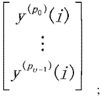
- determining the following signal vector formed by v DMRS ports:

- mapping the v data layers to the v DMRS ports according to the following formula, and sending the data layers to a terminal:

- Optionally, the method further includes: determining QCL (Quasi-Co-Location) group information of the one or more DMRS ports; and notifying the terminal of the QCL group information.
- Optionally, if there is only one QCL group or CDM (Code Division Multiplexing) group, then P0<P1<,...,Pv-1.
- Optionally, if there are a plurality of QCL groups or CDM groups, the signal vector formed by the v DMRS ports is determined according to an ordering result of the serial numbers of the v DMRS ports.
- Optionally, the ordering result is obtained by: ordering, within each subset, the serial numbers of DMRS ports in the DMRS port subset to obtain an ordering result, within each subset, of the DMRS port serial numbers corresponding to the DMRS port subset; and performing ordering between DMRS port subsets based on the ordering result, within each subset, of the DMRS port serial numbers corresponding to the DMRS port subset, where each DMRS port subset is a set formed by DMRS ports included in a CDM group or QCL group.
- Optionally, ordering between DMRS port subsets is performed by: performing ordering between DMRS port subsets based on the smallest DMRS port serial number in each DMRS port subset; or performing ordering between DMRS port subsets based on a serial number of the CDM group or QCL group corresponding to each DMRS port subset; or performing ordering between DMRS port subsets based on the number of DMRS ports included in each DMRS port subset.
- Optionally, the QCL group information specifically includes one of the following information: in a DMRS pattern, an identifier corresponding to a reference signal having a QCL relationship with each CDM group, where DMRS ports included in a CDM group having the same identifier form a same QCL group, and the identifiers corresponding to DMRS ports of different QCL groups are different, and the identifiers corresponding to DMRS ports of a same QCL group are same; a CDM group included in a QCL group; and a list of DMRS ports included in a QCL group.
- Optionally, the QCL group information of the one or more DMRS ports is notified to the terminal in a broadcast, multicast or terminal-specific manner, through RRC (Radio Resource Control) configuration or a MAC (Media Access Control) CE (Control Element) or DCI (Downlink Control Information).
- Correspondingly, on the terminal side, a data receiving method provided in an embodiment of the present application includes: determining a preset DMRS port ordering rule; and receiving one or more sent data layers mapped to one or more DMRS ports according to the preset DMRS port ordering rule.
- Optionally, receiving one or more sent data layer mapped to one or more DMRS ports according to the preset DMRS port ordering rule specifically includes:
- based on a number v of MIMO parallel transmission data layers, arranging the one or more data layers into the following transmission signal vector according to serial numbers:

- determining the following signal vector formed by v DMRS ports:

- receiving the one or more sent data layers mapped to the one or more DMRS ports used in transmission, according to the following formula:

- Optionally, the method further includes: receiving QCL group information of the one or more DMRS ports notified by the network side.
- Optionally, if there is only one QCL group or CDM group, then P0<P1<,..., Pv-1.
- Optionally, if there are a plurality of QCL groups or CDM groups, the signal vector formed by the v DMRS ports is determined according to an ordering result of the serial numbers of the v DMRS ports.
- Optionally, the ordering result is obtained by: ordering, within each subset, the serial numbers of DMRS ports in the DMRS port subset to obtain an ordering result, within each subset, of the DMRS port serial numbers corresponding to the DMRS port subset; and performing ordering between DMRS port subsets based on the ordering result, within each subset, of the DMRS port serial numbers corresponding to the DMRS port subset, where each DMRS port subset is a set formed by DMRS ports included in a CDM group or QCL group.
- Optionally, ordering between DMRS port subsets is performed by: performing ordering between DMRS port subsets based on the smallest DMRS port serial number in each DMRS port subset; or performing ordering between DMRS port subsets based on a serial number of the CDM group or QCL group corresponding to each DMRS port subset; or performing ordering between DMRS port subsets based on the number of DMRS ports included in each DMRS port subset.
- Optionally, the QCL group information specifically includes one of the following information: in a DMRS pattern, an identifier corresponding to a reference signal having a QCL relationship with each CDM group, where DMRS ports included in a CDM group having the same identifier form a same QCL group, and the identifiers corresponding to DMRS ports of different QCL groups are different, and the identifiers corresponding to DMRS ports of a same QCL group are same; a CDM group included in a QCL group; and a list of DMRS ports included in a QCL group.
- Optionally, the notification is received in a broadcast, multicast, or terminal-specific manner, and the QCL group information of the one or more DMRS ports is acquired from RRC configuration or an MAC CE or DCI in the notification.
- On the network side, a data transmission apparatus provided in an embodiment of the present application includes a memory and a processor, where the memory is configured to store program instructions, and the processor is configured to call the program instructions stored in the memory, and execute the following steps according to obtained programs: determining a preset DMRS port ordering rule; and mapping one or more data layers to one or more DMRS ports used in transmission according to the preset DMRS port ordering rule, and sending the one or more data layers to a terminal.
- Optionally, the processor mapping the one or more data layers to the one or more DMRS ports used in transmission according to the preset DMRS port ordering rule, and sending the one or more data layers to the terminal specifically includes:
- based on a number v of MIMO parallel transmission data layers, arranging the one or more data layers into the following transmission signal vector according to serial numbers:

- determining the following signal vector formed by v DMRS ports:
- mapping the v data layers to the v DMRS ports according to the following formula, and sending the data layers to a terminal:

- Optionally, the processor is further configured to: determine QCL group information of the one or more DMRS ports; and notify the terminal of the QCL group information.
- Optionally, if there is only one QCL group or CDM group, then P0<P1<,..., Pv-1.
- Optionally, if there are a plurality of QCL groups or CDM groups, the signal vector formed by the v DMRS ports is determined according to an ordering result of the serial numbers of the v DMRS ports.
- Optionally, the ordering result is obtained by: ordering, within each subset, the serial numbers of DMRS ports in the DMRS port subset to obtain an ordering result, within each subset, of the DMRS port serial numbers corresponding to the DMRS port subset; and performing ordering between DMRS port subsets based on the ordering result, within each subset, of the DMRS port serial numbers corresponding to the DMRS port subset, where each DMRS port subset is a set formed by DMRS ports included in a CDM group or QCL group.
- Optionally, ordering between DMRS port subsets is performed by: performing ordering between DMRS port subsets based on the smallest DMRS port serial number in each DMRS port subset; or performing ordering between DMRS port subsets based on a serial number of the CDM group or QCL group corresponding to each DMRS port subset; or performing ordering between DMRS port subsets based on the number of DMRS ports included in each DMRS port subset.
- Optionally, the QCL group information specifically includes one of the following information: in a DMRS pattern, an identifier corresponding to a reference signal having a QCL relationship with each CDM group, where DMRS ports included in a CDM group having the same identifier form a same QCL group, and the identifiers corresponding to DMRS ports of different QCL groups are different, and the identifiers corresponding to DMRS ports of a same QCL group are same; a CDM group included in a QCL group; and a list of DMRS ports included in a QCL group.
- Optionally, the processor notifies the QCL group information of the one or more DMRS ports to the terminal in a broadcast, multicast or terminal-specific manner, through RRC configuration or an MAC CE or DCI.
- On the terminal side, a data receiving apparatus provided in an embodiment of the present application includes a memory and a processor, where the memory is configured to store program instructions, and the processor is configured to call the program instructions stored in the memory, and execute the following steps according to obtained programs: determining a preset DMRS port ordering rule; and receiving one or more sent data layers mapped to one or more DMRS ports according to the preset DMRS port ordering rule.
- Optionally, the receiving one or more sent data layers mapped to one or more DMRS ports according to the preset DMRS port ordering rule specifically includes:
- based on a number v of MIMO parallel transmission data layers, arranging the one or more data layers into the following transmission signal vector according to serial numbers:

- determining the following signal vector formed by v DMRS ports:

- receiving a sent data layer mapped to a DMRS port used in transmission, according to the following formula:

- Optionally, the processor is further configured to receive QCL group information of the one or more DMRS ports notified by the network side.
- Optionally, if there is only one QCL group or CDM group, then P0<P1<,..., Pv-1.
- Optionally, if there are a plurality of QCL groups or CDM groups, the signal vector formed by the v DMRS ports is determined according to an ordering result of the serial numbers of the v DMRS ports.
- Optionally, the ordering result is obtained by: ordering, within each subset, the serial numbers of DMRS ports in the DMRS port subset to obtain an ordering result, within each subset, of the DMRS port serial numbers corresponding to the DMRS port subset; and performing ordering between DMRS port subsets based on the ordering result, within each subset, of the DMRS port serial numbers corresponding to the DMRS port subset, where each DMRS port subset is a set formed by DMRS ports included in a CDM group or QCL group.
- Optionally, the processor performs ordering between DMRS port subsets by: performing ordering between DMRS port subsets based on the smallest DMRS port serial number in each DMRS port subset; or performing ordering between DMRS port subsets based on a serial number of the CDM group or QCL group corresponding to each DMRS port subset; or performing ordering between DMRS port subsets based on the number of DMRS ports included in each DMRS port subset.
- Optionally, the QCL group information specifically includes one of the following information: in a DMRS pattern, an identifier corresponding to a reference signal having a QCL relationship with each CDM group, where DMRS ports included in a CDM group having the same identifier form a same QCL group, and the identifiers corresponding to DMRS ports of different QCL groups are different, and the identifiers corresponding to DMRS ports of a same QCL group are same; a CDM group included in a QCL group; and a list of DMRS ports included in a QCL group.
- Optionally, the processor receives the notification in a broadcast, multicast, or terminal-specific manner, and acquires the QCL group information of the one or more DMRS ports from RRC configuration or a MAC CE or DCI in the notification.
- On the network side, another data sending apparatus provided in an embodiment of the present application includes: a determining unit configured to determine a preset DMRS port ordering rule; and a sending unit configured to map one or more data layers to one or more DMRS ports used in transmission according to the preset DMRS port ordering rule, and send the one or more data layers to a terminal.
- On the terminal side, another data receiving apparatus provided in an embodiment of the present application includes: a determining unit configured to determine a preset DMRS port ordering rule; and a receiving unit configured to receive one or more sent data layer mapped to one or more DMRS ports according to the preset DMRS port ordering rule.
- Another embodiment of the present application provides a computer storage medium storing computer-executable instructions, which are used for causing a computer to execute any foregoing method.
- To describe technical solutions in the embodiments of the present application more clearly, drawings that need to be used in description of the embodiments will be introduced briefly below. Obviously, the drawings described below are merely some embodiments of the present application, and those of ordinary skill in the art can obtain other drawings according to these drawings without using any inventive skill.
-
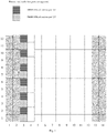
Fig. 1 is a schematic diagram of a first DMRS pattern provided in an embodiment of the present application. -
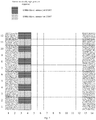
Fig. 2 is a schematic diagram of a second DMRS pattern provided in an embodiment of the present application. -
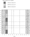
Fig. 3 is a schematic diagram of a third DMRS pattern provided in an embodiment of the present application. -
Fig. 4 is a schematic diagram of a fourth DMRS pattern provided in an embodiment of the present application. -
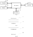
Fig. 5 is a flow diagram of a data sending method provided in an embodiment of the present application. -
Fig. 6 is a flow diagram of a data receiving method provided in an embodiment of the present application. -
Fig. 7 is a structure diagram of a data sending apparatus provided in an embodiment of the present application. -
Fig. 8 is a structure diagram of a data receiving apparatus provided in an embodiment of the present application. -
Fig. 9 is a structure diagram of another data sending apparatus provided in an embodiment of the present application. -
Fig. 10 is a structure diagram of another data receiving apparatus provided in an embodiment of the present application. - Embodiments of the present application provide a data transmission method and apparatus and a computer storage medium, so as to map a data layer to a DMRS port used in transmission according to a preset DMRS port ordering rule, and perform transmission.
- DMRS basic pattern (front-load DMRS) configurations include the following.
- The number of DMRS symbol is 1: by using combination (comb) 2+ cyclic shifts (CS) 2, maximally 4 ports are supported.
- As shown
Fig. 1 , comb2 indicates frequency domain multiplexing. For example,ports 0 and 2 have a multiplexing relationship of comb2. CS2 indicates that a sequence between ports is multiplexed by cyclic shifts. For example,ports 0 and 1 have a multiplexing relationship of CS2. - The number of DMRS symbols is 2: by using comb2+CS2+TD-OCC({1, 1} and {1, -1}), maximally 8 ports are supported. TD-OCC ({1, 1} and {1, -1}) indicate that time-domain orthogonal cover code (TD-OCC) multiplexing is adopted between two ports, and {1, 1} and {1, -1} are multiplexing coefficients of the two ports, respectively.
- As shown in
Fig. 2 , TD-OCC indicates time-domain orthogonal cover code (OCC) multiplexing. For example, time-domain OCC multiplexing is adopted between ports 0/1 and 4/5. CS2 multiplexing is adopted between port 0 andport 1, CS2 multiplexing is adopted betweenport 4 andport 5, and time domain OCC multiplexing is adopted between port 0/1 andport 4/5. - The number of DMRS symbol is 1: by using 2-FD-OCC (adjacent frequency domain resource element (RE)), maximally 6 ports are supported.
- As shown in
Fig. 3 , 2-FD-OCC indicates frequency domain OCC multiplexing. For example, frequency domain OCC multiplexing is adopted betweenports 0 and 1. In addition, frequency-division multiplexing (FDM) is adopted with other ports. For example, FDM is used between ports 0/1 and 2/3. - The number of DMRS symbols is 2: by adopting 2-FD-OCC (adjacent frequency domain RE) + TD-OCC ({1, 1} and {1, -1}), maximally 12 ports are supported.
- As shown in
Fig. 4 , TD-OCC indicates time-domain OCC multiplexing. For example, time-domain OCC multiplexing is adopted between ports 0/1 and 6/7. - It can be seen from the various pilot patterns of the DMRS described above that in
configuration 1, if the number of maximally supported ports does not exceed 4, the pattern inFig. 1 can be used for configuration, and if the number of maximally supported ports exceeds 4, but does not exceed 8, the pattern inFig. 2 can be used for configuration; and inconfiguration 2, if the number of maximally supported ports does not exceed 6, the pattern inFig. 3 can be used for configuration; and if the number of maximally supported ports exceeds 6, but does not exceed 12, the pattern inFig. 4 can be used for configuration. The number of ports described here refers to the total number of ports of all terminals multiplexed at each resource location. - Additionally, in
Figs. 1 to 4 , the first two columns represent control symbol fields, that is, symbol positions required for a downlink control channel; and the last two columns can be symbol positions required for an uplink control channel, that is, symbol resources of a data channel that cannot be used for a physical downlink shared channel (PDSCH). - In an NR system, multiple transport receive points (TRPs)/antenna panels or sub-arrays may be considered for coordinated transmission. In this case, signals sent by different TRPs /panels may have relatively independent large-scale features, such as an average delay, delay spread, average Doppler shift, Doppler spread, and airspace reception parameter. Therefore, in NR, if large-scale parameters of two or more reference signal channels are consistent, it is called quasi-co-location (QCL). Otherwise, it is called non-QCL. The large-scale parameters are, for example, an average delay, delay spread, Doppler shift, Doppler spread, spatial reception parameter, average received power, and the like. Moreover, the QCL is further explained as follows: the terminal cannot determine that received reference signal ports are from sites or antenna sub-arrays at same or different physical locations, and if parameters (or a subset thereof) such as the average delay, delay spread, Doppler shift, Doppler spread, spatial reception parameter, and average reception power of two reference signal ports are same, the two reference signals can be regarded as quasi-co-located in the sense of the aforementioned large-scale parameters.
- For DMRS ports, the concept of a QCL group is defined in an NR system, that is, a QCL group of DMRS ports (QCL group for short): DMRS ports in a QCL group are QCL, and DMRS ports in different QCL groups are not QCL. It is specified in the NR system that DMRS ports in a same code division multiplexing (CDM) group have a QCL relationship. That is, in a CDM group, reference signal ports occupy the same time-frequency resource, and are distinguished by orthogonal codewords. Using
Fig. 4 as an example, due to characteristics of the DMRS design, in the case of one DMRS symbol, ports 0/1 are in a CDM relationship,ports 2/3 are in a CDM relationship, and ports 0/1 andport 2/3 are in an FDM relationship. InFigs. 1 to 4 , adjacent blocks that are filled in a same way constitute a CDM group. Each data channel can support two QCL groups. The data channel is, for example, a physical downlink shared channel (PDSCH). - A QCL group of DMRS ports described in the embodiments of the present application may be referred to as a QCL group for short, and may also be referred to as a DMRS group.
- The DMRS port described in the embodiments of the present application may be referred to as a port for short, and may also be referred to as an antenna port.
- A specific scheme provided in an embodiment of the present application includes the following steps.
- Step I: the network side indicates QCL group information (for indicating QCL grouping of DMRS ports) of DMRS ports through control signaling. The content of the QCL group information of the DMRS ports is optionally content as indicated in the following mode 1- 1, 1-2 or 1-3.
- CDM groups in a DMRS pattern are denoted by:
CDM group 1,CDM group 2, ..., CDM group N. For example, according to the current DMRS pattern (referring toFigs. 1 to 4 ), there are a maximum of two CDM groups inDMRS configuration type 1 and a maximum of three CDM groups inDMRS configuration type 2. - Mode 1-1 (for example, notification can be made by DCI or MAC CE).
- An identifier corresponding to a reference signal having a QCL relationship with each CDM group (that is, a QCL reference source of each DMRS port in a CDM group n) in a DMRS pattern is respectively notified through control signaling. For example, a reference signal having a QCL relationship with the CDM group n is Ref_n, and a corresponding identifier is ID_n; that is, only the ID_n needs to be notified, and the terminal can determine, according to the ID_n, that the reference signal having a QCL relationship with the CDM group n is Ref_n, and perform QCL grouping according to QCL reference sources; that is, DMRS ports included in CDM groups having the same identifier ID_n form a same QCL group, and the identifiers ID_n corresponding to DMRS ports of different QCL groups are different, and the identifiers ID_n corresponding to DMRS ports of a same QCL group are same.
- For CDM groups with a same reference source reference signal identifier, a set formed by DMRS ports included therein can be considered as one QCL group of DMRS ports. It should be noted that "one" here means that one group, but not one DMRS port, that is one QCL group, or DMRS group for short.
- Mode 1-2: CDM groups included in a QCL group i are directly indicated through control signaling, For example, for
DMRS configuration type 2, the control signaling can indicate thatQCL group 1 includesCDM groups QCL group 2 includesCDM group 3. - Mode 1-3: A list of DMRS ports included in a QCL group i is directly indicated through control signaling. For example, for
DMRS configuration type 2, if the number of data layers is 8, the control signaling can indicate thatQCL group 1 includesDMRS ports QCL group 2 includesDMRS ports - In the above process, the control information (i.e. QCL group information of DMRS ports) for indicating QCL grouping of DMRS ports can be notified to the terminal in a broadcast, multicast, or terminal-specific manner through radio resource control (RRC) configuration or media access control (MAC) control element (CE), or downlink control information (DCI).
- Moreover, it should be noted that, for the present application, step I described above is not a step that must be performed, but an optional step; that is, the following steps can exist independently. If step I exists, the terminal can further determine an ordering manner of the DMRS ports occupied by the terminal, according to the QCL group information of the DMRS ports notified by the network side, in conjunction with a preset ordering rule of DMRS ports (the specific rule can be determined according to actual needs; exemplary description of some rules are provided in the following embodiments, but the present invention is not limited to the rules).
- Step II: based on a number (i.e. a number of ranks) v of multiple-input multiple-output (MIMO) parallel transmission data layers, arranging the transmission data layers (each data layer is a data stream) into the following transmission signal vector according to serial numbers:

- That is, X is a column vector with v elements, and superscripts 0, ..., v-1 are serial numbers of the elements, i.e. serial numbers of the data layers, where


- Let Y be a signal vector including v DMRS ports, where ports included in a set {P0,..., Pv-1} are indicated by the DCI, and the ordering manner is determined by step III.

- Y is a column vector with v elements, and superscripts P0,...,
P v-1 are numerals of the elements in y, and the superscripts P0, ..., Pv-1 are serial numbers of v DMRS ports,

- Step III: mapping one or more data layers to one or more DMRS ports used in transmission according to a preset DMRS port ordering rule, and performing transmission. Optional modes are as illustrated in the following modes 3-1, 3-2, 3-3, 3-4, 3-5.
- Case I: If there is only one QCL group or CDM group:
- the serial numbers of the v DMRS ports allocated to the terminal in the DCI are ordered so that P0<P1<,..., Pv-1, which is a preset DMRS port ordering rule; and
- the v data layers (also called data layers of data, each data layer data is each data layer, and the number v of data layers of data for simultaneous parallel transmission is the number v of data layers of data for simultaneous parallel transmission) are mapped to the v DMRS ports.

- The above formula indicates that the corresponding elements in the vector are equal; that is, a data layer y (p
0 )(i) is mapped to a DMRS port x (0)(i) used in transmission, and similarly, a data layer y (pυ-1 )(i) is mapped to a DMRS port x (υ-1)(i) used in transmission; the same formula is used similarly in the following mapping, which will not be described here. - For example, for
DMRS configuration type 2, if the number of data layers is v = 8, andDMRS ports ports DMRS ports - Case II: If there are multiple QCL groups or CDM groups:
- ordering is performed within a port group, that is, ordering, within each subset, the serial numbers of DMRS ports in the DMRS port subset to obtain an ordering result, within each subset, of the DMRS port serial numbers corresponding to the DMRS port subset, specifically including: according to the QCL group information of the DMRS ports configured/indicated in step I, ordering the DMRS ports indicated in the DCI, in the respective QCL groups to which the DMRS ports belong, where the serial numbers of the DMRS ports in each QCL group are arranged in ascending order (from small to large); and
- ordering is performed among port groups, that is, performing ordering between DMRS port subsets based on the ordering result, within each subset, of the DMRS port serial numbers corresponding to the DMRS port subset, specifically including: in the port subsets obtained by grouping and ordering as described above, the port subsets are further ordered in ascending order (from small to large) based on the smallest DMRS port serial number in each subset; that is, among the subsets, a subset in which the smallest DMRS port serial number is smaller is prior in the order (of course, ordering of the DMRS port serial numbers among the subsets may also be performed according to other principles; for example, among the subsets, a subset in which the largest DMRS port serial number is larger is prior in the order), where each port subset, subset for short, is DMRS ports in one QCL group.
- Each DMRS port subset described in the embodiments of the present application is a set formed by DMRS ports included in each CDM group or QCL group.
- The combination of ordering within a port group and the ordering among port groups described above can be regarded as another preset DMRS port ordering rule. The same applies to the following modes, and will not be repeated later.
- The v DMRS ports are arranged into a vector according to an ordering result described above:

- The v data layers are mapped to the v DMRS ports according to the following formula:

- For example, for
DMRS configuration type 2, if the number of data layers is v = 8, andDMRS ports ports port subset 1 is 0, and is smaller than the smallest DMRS portserial number 2 insubset 2, the port subsets are further ordered; that is,subset 1 is arranged prior tosubset 2, and the ports are in the order of 0, 1, 6, 7, 2, 3, 8, 9; as a result, P0, P1, P2, P3 are equal to 0, 1, 6, 7, respectively, and P4, P5, P6, P7 are equal to 2, 3, 8, 9, respectively. Finally, the v data layers are mapped to the v DMRS ports according to the following formula:
- That is, data layers 0, 1, 2, 3, 4, 5, 6, 7, 8 are mapped to
DMRS ports - Ordering within a port group: according to the CDM group relationships of the DMRS ports in the DMRS pattern, the DMRS ports indicated in the DCI are ordered in the respective CDM groups to which the ports belong, where the serial numbers of the DMRS ports in each CDM group are arranged in ascending order (from small to large).
- Ordering among port groups: in the port subsets obtained by grouping and ordering as described above, the port subsets are further ordered in ascending order (from small to large) based on the smallest DMRS port serial number in each subset; that is, a subset in which the smallest DMRS port serial number is smaller is prior in the order, where each subset is DMRS ports in one CDM group.
- The v DMRS ports are arranged into a vector according to ordering described above:

- The v data layers are mapped to the v DMRS ports according to the following formula:

- For example, for
DMRS configuration type 2, if the number of data layers is v = 8, andDMRS ports ports serial number 2 in subset 2 (i.e. ports {2, 3, 8, 9}), the port subsets are further ordered;subset 1 is arranged prior tosubset 2, and the ports are in the order of 0, 1, 6, 7, 2, 3, 8, 9; as a result, P0, P1, P2, P3 are equal to 0, 1, 6, 7, respectively, and P4, P5, P6, P7 are equal to 2, 3, 8, 9, respectively. Finally, the v data layers are mapped to the v DMRS ports according to the following formula:
- That is, data layers 0, 1, 2, 3, 4, 5, 6, 7, 8 are mapped to
DMRS ports - Ordering within a port group: according to the CDM group relationships of the DMRS ports in the DMRS pattern, the DMRS ports indicated in the DCI are ordered in the respective CDM groups to which the ports belong, where the serial numbers of the DMRS ports in each group are arranged in ascending order (from small to large).
- Ordering between port groups: the aforementioned subsets are arranged in ascending order based on the serial numbers of the CDM groups to which they belong.
- The v DMRS ports are arranged into a vector according to ordering described above:

- The v data layers are mapped to the v DMRS ports according to the following formula:

- For example, for
DMRS configuration type 2, if the number of data layers is v = 8, andDMRS ports ports CDM group 1, CDM group 2}), where subset 1 (i.e. ports {0, 1, 6, 7}) is arranged prior to subset 2 (i.e. port {2, 3, 8, 9}), and the ports are in the order of 0, 1, 6, 7, 2, 3, 8, 9; as a result, P0, P1, P2, P3 are equal to 0, 1, 6, 7, respectively, and P4, P5, P6, P7 are equal to 2, 3, 8, 9, respectively . Finally, the v data layers are mapped to the v DMRS ports according to the following formula:
- That is, data layers 0, 1, 2, 3, 4, 5, 6, 7, 8 are mapped to
DMRS ports - Case I: If there is only one QCL group or CDM group: the v DMRS ports allocated to the terminal in the DCI are ordered to ensure P0<P1<,..., Pv-1.
- The v data layers are mapped to the v DMRS ports according to the following formula:

- For example, for
DMRS configuration type 2, if the number of data layers is v = 8, andDMRS ports ports DMRS ports - Case II: If there is more than one QCL group:
- Ordering within a port group: according to the QCL group relationships of the DMRS ports configured/indicated in step I, the DMRS ports indicated in the DCI are ordered in the respective QCL groups to which the DMRS ports belong, where the serial numbers of the DMRS ports in each QCL group are arranged in ascending order (from small to large).
- Ordering between port groups: in the port subsets obtained by grouping and ordering as described above, the port subsets are further ordered in ascending order (from small to large) based on the number of DMRS ports included in each subset; that is, a subset in which the number of DMRS ports is smaller is prior in the order (of course, a subset including a larger number of DMRS ports may also be prior in the order), where a subset is a set formed by DMRS ports in one QCL group.
- The v DMRS ports are arranged into a vector according to ordering described above:

- The v data layers are mapped to the v DMRS ports according to the following formula:

- For example, for
DMRS configuration type 2, if the number of data layers is v = 7, for example, data layers 0, 1, 2, 3, 4, 5, 6, 7, respectively, andDMRS ports ports port subset 1 includes 4 DMRS ports, which is greater than the number (3) of DMRS ports insubset 2, the port subsets are further ordered to obtain {subset 2, subset 1}; that is, P0, P1, P2 are equal to 2, 3, 8, respectively, and P3, P4, P5, P6, P7 are equal to 0, 1, 6, 7, respectively. Finally, the v data layers are mapped to the v DMRS ports according to the following formula: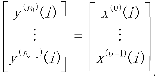
- That is, the data layers 0, 1, 2, 3, 4, 5, 6, 7 are mapped to
DMRS ports - Ordering within a port group: according to the CDM group relationships of the DMRS ports in the DMRS pattern, the DMRS ports indicated in the DCI are ordered in the respective CDM groups to which the ports belong, where the serial numbers of the DMRS ports in each group are arranged in ascending order (from small to large).
- Ordering between port groups: the aforementioned subsets are arranged in the order of from smaller to larger number of DMRS ports included therein; that is, a subset including a smaller number of DMRS ports is prior in the order (of course, a subset including a larger number of DMRS ports may also be prior in the order).
- The v DMRS ports are arranged into a vector according to ordering described above:

- The v data layers are mapped to the v DMRS ports according to the following formula:

- For example, for
DMRS configuration type 2, if the number of data layers is v = 7, for example, data layers 0, 1, 2, 3, 4, 5, 6, 7, respectively, andDMRS ports ports CDM group 1, CDM group 2}); as a result, P0, P1, P2 are equal to 2, 3, 8, respectively, and P3, P4, P5, P6, P7 are equal to 0, 1, 6, 7, respectively. Finally, the v data layers are mapped to the v DMRS ports according to the following formula:
- That is, the data layers 0, 1, 2, 3, 4, 5, 6, 7 are mapped to
DMRS ports - It should be noted that ordering from small to large mentioned anywhere of the foregoing embodiments can be similarly replaced with ordering from large to small (descending order), and the specific way of ordering is not limited in the embodiments of the present application. Furthermore, the embodiments of the present application are not limited to the foregoing several methods for determining a vector composed of v DMRS ports, nor do they define the specific manners of mapping between the v DMRS ports and the v data layers. Other alternatives absolutely conceivable to those skilled in the art based on the embodiments of the present application are within the scope of protection of the present application.
- In addition, the preset DMRS port ordering rule described in the embodiments of the present application can be preset on the network side and the on the terminal side; that is, the same DMRS port ordering rule is set on both sides; and the same formula can be set on the network side and the terminal side, so as to map the data layers to the DMRS ports used in transmission in the same way.
- In addition, the aforementioned steps II and III can be combined into one step.
- In summary, referring to
Fig. 5 , on the network side, a data sending method provided in an embodiment of the present application includes the following operations. - S101. determining a preset demodulation reference signal (DMRS) port ordering rule.
- S102. mapping one or more data layers to one or more DMRS ports used in transmission according to the preset DMRS port ordering rule, and sending the one or more data layers to a terminal.
- By adopting the data sending method, a preset demodulation reference signal (DMRS) port ordering rule is determined; and a data layer is mapped to a DMRS port used in transmission according to the preset DMRS port ordering rule, and the data layer is sent to a terminal, so as to map a data layer to a DMRS port used in transmission according to a preset DMRS port ordering rule, and perform transmission.
- Optionally, mapping the one or more data layers to the one or more DMRS ports used in transmission according to the preset DMRS port ordering rule, and sending the one or more data layers to the terminal specifically includes:
- based on a number v of multiple-input multiple-output (MIMO) parallel transmission data layers, arranging the one or more data layers into the following transmission signal vector according to serial numbers:

- determining the following signal vector formed by v DMRS ports:
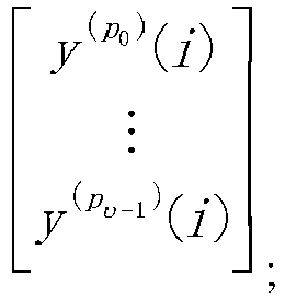
- mapping the v data layers to the v DMRS ports according to the following formula, and sending the data layers:

- Optionally, the method further includes: determining quasi-co-location (QCL) group information of the one or more DMRS ports; and notifying the terminal of the QCL group information.
- Optionally, if there is only one QCL group or CDM group, then P0<P1<,..., Pv-1. Examples are case I in mode 3-1 and case I in mode 3-4.
- Optionally, if there are a plurality of QCL groups or CDM groups, the signal vector formed by the v DMRS ports is determined according to an ordering result of the serial numbers of the v DMRS ports. Examples are case II in mode 3-1; case II in mode 3-4; and mode 3-2, mode 3-3, and mode 3-5.
- Optionally, the ordering result is obtained by: ordering, within each subset, the serial numbers of DMRS ports in the DMRS port subset to obtain an ordering result, within each subset, of the DMRS port serial numbers corresponding to the DMRS port subset; and performing ordering between DMRS port subsets based on the ordering result, within each subset, of the DMRS port serial numbers corresponding to the DMRS port subset, where each DMRS port subset is a set formed by DMRS ports included in a CDM group or QCL group.
- Optionally, ordering between DMRS port subsets is performed by: performing ordering between DMRS port subsets based on the smallest DMRS port serial number in each DMRS port subset, such as in case II of mode 3-1 and mode 3-2 described above; or performing ordering between DMRS port subsets based on a serial number of the CDM group or QCL group corresponding to each DMRS port subset, such as in mode 3-3 described above; or performing ordering between DMRS port subsets based on the number of DMRS ports included in each DMRS port subset, such as in mode 3-5 described above.
- Optionally, the QCL group information specifically includes one of the following information (that is, content described in the aforementioned mode 1-1, 1-2, or 1-3): in a DMRS pattern, an identifier corresponding to a reference signal having a QCL relationship with each code division multiplexing (CDM) group, where DMRS ports included in a CDM group having the same identifier form a same QCL group, and the identifiers corresponding to DMRS ports of different QCL groups are different, and the identifiers corresponding to DMRS ports of a same QCL group are same; a CDM group included in a QCL group; and a list of DMRS ports included in a QCL group.
- Optionally, the QCL group information of the one or more DMRS ports is notified to the terminal in a broadcast, multicast or terminal-specific manner, through radio resource control (RRC) configuration or a media access control (MAC) control element (CE) or downlink control information (DCI).
- Correspondingly, referring to
Fig. 6 , at the terminal side, a data receiving method provided in an embodiment of the present application includes the following operations. - S201. determining a preset DMRS port ordering rule.
- S202. receiving one or more sent data layers mapped to one or more DMRS ports according to the preset DMRS port ordering rule.
- Optionally, receiving one or more sent data layers mapped to one or more DMRS ports according to the preset DMRS port ordering rule specifically includes:
- based on a number v of multiple-input multiple-output (MIMO) parallel transmission data layers, arranging the one or more data layers into the following transmission signal vector according to serial numbers:

- determining the following signal vector formed by v DMRS ports:

- receiving the one or more sent data layers mapped to the one or more DMRS ports used in transmission, according to the following formula:

- Optionally, the method further includes: receiving quasi-co-location (QCL) group information of the one or more DMRS ports notified by the network side.
- The terminal can further determine an ordering manner of the DMRS ports occupied by the terminal, according to the QCL group information of the DMRS ports, in conjunction with a preset ordering rule of DMRS port. Specifically, for example, content of ordering within a port group and ordering between port groups is involved in each of the aforementioned modes.
- Optionally, if there is only one QCL group or CDM group, then P0<P1<,..., Pv-1.
- Optionally, if there are a plurality of QCL groups or CDM groups, the signal vector formed by the v DMRS ports is determined according to an ordering result of the serial numbers of the v DMRS ports.
- Optionally, the ordering result is obtained by: ordering, within each subset, the serial numbers of DMRS ports in the DMRS port subset to obtain an ordering result, within each subset, of the DMRS port serial numbers corresponding to the DMRS port subset; and performing ordering between DMRS port subsets based on the ordering result, within each subset, of the DMRS port serial numbers corresponding to the DMRS port subset, where each DMRS port subset is a set formed by DMRS ports included in a CDM group or QCL group.
- Optionally, ordering between DMRS port subsets is performed by: performing ordering between DMRS port subsets based on the smallest DMRS port serial number in each DMRS port subset; or performing ordering between DMRS port subsets based on a serial number of the CDM group or QCL group corresponding to each DMRS port subset; or performing ordering between DMRS port subsets based on the number of DMRS ports included in each DMRS port subset.
- Optionally, the QCL group information specifically includes one of the following information: in a DMRS pattern, an identifier corresponding to a reference signal having a QCL relationship with each code division multiplexing (CDM) group, where DMRS ports included in a CDM group having the same identifier form a same QCL group, and the identifiers corresponding to DMRS ports of different QCL groups are different, and the identifiers corresponding to DMRS ports of a same QCL group are same; a CDM group included in a QCL group; and a list of DMRS ports included in a QCL group.
- Optionally, the notification is received in a broadcast, multicast, or terminal-specific manner, and the QCL group information of the one or more DMRS ports is acquired from radio resource control (RRC) configuration or a media access control (MAC) control element (CE) or downlink control information (DCI) in the notification.
- On the network side, referring to
Fig. 7 , a data sending apparatus provided in an embodiment of the present application includes amemory 520 and aprocessor 500, where thememory 520 is configured to store program instructions, and theprocessor 500 is configured to call the program instructions stored in thememory 520, and execute the following steps according to obtained programs: determining a DMRS port ordering rule; and mapping one or more data layers to one or more DMRS ports used in transmission according to the preset DMRS port ordering rule, and sending the one or more data layers to a terminal through atransceiver 510. - It should be noted that a bus interface, the
transceiver 510, and the like inFig. 7 can all exist as optional devices in a data sending apparatus provided in the embodiment of the present application, and are not indispensable. - Optionally, the
processor 500 mapping the one or more data layers to the one or more DMRS ports used in transmission according to the preset DMRS port ordering rule, and sending the one or more data layers to the terminal specifically includes: - based on a number v of multiple-input multiple-output (MIMO) parallel transmission data layers, arranging the one or more data layers into the following transmission signal vector according to serial numbers:

- determining the following signal vector formed by v DMRS ports:

- mapping the v data layers to the v DMRS ports according to the following formula, and sending the data layers to a terminal:

- Optionally, the
processor 500 is further configured to: determine quasi-co-location (QCL) group information of the one or more DMRS ports; and notify the terminal of the QCL group information. - Optionally, if there is only one QCL group or CDM group, then P0<P1<,..., Pv-1.
- Optionally, if there are a plurality of QCL groups or CDM groups, the signal vector formed by the v DMRS ports is determined according to an ordering result of the serial numbers of the v DMRS ports.
- Optionally, the ordering result is obtained by: ordering, within each subset, the serial numbers of DMRS ports in the DMRS port subset to obtain an ordering result, within each subset, of the DMRS port serial numbers corresponding to the DMRS port subset; and performing ordering between DMRS port subsets based on the ordering result, within each subset, of the DMRS port serial numbers corresponding to the DMRS port subset; where each DMRS port subset is a set formed by DMRS ports included in a CDM group or QCL group.
- Optionally, ordering between DMRS port subsets is performed by: performing ordering between DMRS port subsets based on the smallest DMRS port serial number in each DMRS port subset; or performing ordering between DMRS port subsets based on a serial number of the CDM group or QCL group corresponding to each DMRS port subset; or performing ordering between DMRS port subsets based on the number of DMRS ports included in each DMRS port subset.
- Optionally, the QCL group information specifically includes one of the following information: in a DMRS pattern, an identifier corresponding to a reference signal having a QCL relationship with each code division multiplexing (CDM) group, where DMRS ports included in a CDM group having the same identifier form a same QCL group, and the identifiers corresponding to DMRS ports of different QCL groups are different, and the identifiers corresponding to DMRS ports of a same QCL group are same; a CDM group included in a QCL group; and a list of DMRS ports included in a QCL group.
- Optionally, the
processor 500 notifies the QCL group information of the one or more DMRS ports to the terminal in a broadcast, multicast or terminal-specific manner, through radio resource control (RRC) configuration or a media access control (MAC) control element (CE) or downlink control information (DCI). - The
transceiver 510 is configured to receive and send data under the control of theprocessor 500. - In
Fig. 7 , the bus architecture can include any number of interconnected buses and bridges, specifically linking together various circuits of one or more processors represented by theprocessor 500 and a memory represented by thememory 520. The bus architecture may also link together various other circuits of a peripheral device, a voltage stabilizer, a power management circuit and the like, which are all known in the art and thus not further described herein. A bus interface provides an interface. Thetransceiver 510 can be multiple elements, including a transmitter and a transceiver, providing a unit for communicating with various other apparatuses over a transmission medium. Theprocessor 500 is responsible for managing the bus architecture and general processing, and thememory 520 can store data used by theprocessor 500 when the processor performs operations. - The
processor 500 can be a central processing unit (CPU), an application specific integrated circuit (ASIC), a field-programmable gate array (FPGA), or a complex programmable logic device (CPLD). - Referring to
Fig. 8 , on the terminal side, a data receiving apparatus provided in an embodiment of the present application includes amemory 620 and aprocessor 600, where thememory 620 is configured to store program instructions, and theprocessor 600 is configured to call the program instructions stored in thememory 620, and execute the following steps according to an obtained program: determining a preset DMRS port ordering rule; and receiving, by atransceiver 610, one or more sent data layers mapped to one or more DMRS ports according to the preset DMRS port ordering rule. - It should be noted that the devices other than the
memory 620 and theprocessor 600 inFig. 8 are optional devices that exist in a data receiving apparatus provided in the embodiment of the present application, and are not indispensable devices. - Optionally, receiving one or more sent data layers mapped to one or more DMRS ports according to the preset DMRS port ordering rule specifically includes:
- based on a number v of multiple-input multiple-output (MIMO) parallel transmission data layers, arranging the one or more data layers into the following transmission signal vector according to serial numbers:

- determining the following signal vector formed by v DMRS ports:

- receiving a sent data layer mapped to a DMRS port used in transmission, according to the following formula:

- Optionally, the
processor 600 is further configured to receive quasi-co-located QCL group information of the one or more DMRS ports notified by the network side. - Optionally, if there is only one QCL group or CDM group, then P0<P1<,..., Pv-1.
- Optionally, if there are a plurality of QCL groups or CDM groups, the signal vector formed by the v DMRS ports is determined according to an ordering result of the serial numbers of the v DMRS ports.
- Optionally, the ordering result is obtained by: ordering, within each subset, the serial numbers of DMRS ports in the DMRS port subset to obtain an ordering result, within each subset, of the DMRS port serial numbers corresponding to the DMRS port subset; and performing ordering between DMRS port subsets based on the ordering result, within each subset, of the DMRS port serial numbers corresponding to the DMRS port subset; where each DMRS port subset is a set formed by DMRS ports included in a CDM group or QCL group.
- Optionally, the
processor 600 performs ordering between DMRS port subsets by: performing ordering between DMRS port subsets based on the smallest DMRS port serial number in each DMRS port subset; or performing ordering between DMRS port subsets based on a serial number of the CDM group or QCL group corresponding to each DMRS port subset; or performing ordering between DMRS port subsets based on the number of DMRS ports included in each DMRS port subset. - Optionally, the QCL group information specifically includes one of the following information: in a DMRS pattern, an identifier corresponding to a reference signal having a QCL relationship with each code division multiplexing (CDM) group, where DMRS ports included in a CDM group having the same identifier form a same QCL group, and the identifiers corresponding to DMRS ports of different QCL groups are different, and the identifiers corresponding to DMRS ports of a same QCL group are same; a CDM group included in a QCL group; and a list of DMRS ports included in a QCL group.
- Optionally, the
processor 600 receives the notification in a broadcast, multicast, or terminal-specific manner, and acquires the QCL group information of the one or more DMRS ports from radio resource control (RRC) configuration or a media access control (MAC) control element (CE) or downlink control information (DCI) in the notification. - The
transceiver 610 is configured to receive and send data under the control of theprocessor 600. - In
Fig. 8 , the bus architecture can include any number of interconnected buses and bridges, specifically linking together various circuitries of one or more processors represented by theprocessor 600 and a memory represented by thememory 620. The bus architecture may also link together various other circuitry of a peripheral device, a voltage stabilizer, a power management circuit and the like, which are all known in the art and thus not further described herein. A bus interface provides an interface. Thetransceiver 610 can be multiple elements, including a transmitter and a receiver, providing a unit for communicating with various other apparatuses over a transmission medium. For different user equipment, auser interface 630 may also be an interface capable of externally or internally connecting a required device, including but not limited to a keypad, a display, a speaker, a microphone, a joystick, or the like. - The
processor 600 is responsible for managing the bus architecture and general processing, and thememory 620 may store data used by theprocessor 600 when the processor performs operations. - Optionally, the
processor 600 can be a CPU (Central Processing Unit), an ASIC (Application Specific Integrated Circuit), an FPGA (Field-Programmable Gate Array) or a CPLD (Complex Programmable Logic Device). - On the network side, referring to
Fig. 9 , another data sending apparatus provided in an embodiment of the present application includes: a determiningunit 11 configured to determine a preset demodulation reference signal (DMRS) port ordering rule; and a sendingunit 12 configured to map one or more data layers to one or more DMRS ports used in transmission according to the preset DMRS port ordering rule, and send the one or more data layers to a terminal. - On the terminal side, referring to
Fig. 10 , another data receiving apparatus provided in an embodiment of the present application includes: a determiningunit 21 configured to determine a preset DMRS port ordering rule; and a receivingunit 22 configured to receive one or more sent data layer mapped to one or more DMRS ports according to the preset DMRS port ordering rule. - An embodiment of the present application provides a computer storage medium configured to store computer program instructions for the aforementioned computing device, including a program for executing the aforementioned information indicating or determining method.
- The computer storage medium may be any available medium or data storage device that can be accessed by a computer, including but not limited to a magnetic memory (such as a floppy disk, hard disk, magnetic tape, magneto-optical disk (MO), etc.), an optical memory (such as a CD, DVD, BD, HVD, etc.), and a semiconductor memory (such as an ROM, EPROM, EEPROM, non-volatile memory (NAND Flash), and a solid-state drive (SSD)).
- The method provided in the embodiment of the present application may be applied to a terminal device, and may also be applied to a network device.
- The terminal device may also be called user equipment ("UE"), mobile station ("MS"), mobile terminal, etc. Optionally, the terminal can have the ability to communicate with one or more core networks through a radio access network (RAN). For example, the terminal may be a mobile phone (or a "cellular" phone), or a computer with a mobile property. For example, the terminal may also be a portable, pocket-sized, handheld, computer-built or vehicle-mounted mobile apparatus.
- The network device can be a base station (e.g. an access point), which is a device, in an access network, that communicates with a wireless terminal through one or more sectors at an air interface. The base station can be used to perform conversion between a received air frame and IP packet as a router between the wireless terminal and the rest of the access network, where the rest of the access network can include an Internet Protocol (IP) network. The base station may also coordinate attribute management of the air interface. For example, the base station may be a base transceiver station (BTS) in GSM or CDMA, or may be a base station (NodeB) in WCDMA, or may also be an evolved base station (eNodeB or eNB or e-NodeB, evolutional Node B) in LTE, but the embodiments of the present invention are not limited thereto. Those skilled in the art should understand that the embodiments of the present invention can be provided as a method, a system or a computer program product. Therefore, the present application can be in the form of an all-hardware embodiment, an all-software embodiment, or a software and hardware combined embodiment. Moreover, the present application can be in the form of a computer program product implemented on one or more computer usable storage media (including but not limited to magnetic disk memories and optical memories) containing computer usable program codes.
- The present application is described with reference to the flow diagrams and/or block diagrams of the method, device (system) and computer program product according to the embodiments of the present invention. It should be understood that each process and/or block in the flow diagrams and/or block diagrams, as well as combinations of processes and/or blocks in the flow diagrams and/or block diagrams can be implemented by computer program instructions. The computer program instructions can be provided to a processor of a general purpose computer, a special purpose computer, an embedded processor or other programmable data processing device to produce a machine, so that the instructions processed by the processor of the computer or other programmable data processing device generates a device for achieving functions specified in one or more processes of the flow diagrams and/or one or more blocks of the block diagrams.
- The computer program instructions may also be stored in a computer readable memory that can instruct a computer or other programmable data processing device to operate in a specified manner, so that the instructions stored in the computer readable memory generates a manufactured product containing an instruction device, where the instruction device achieves the functions specified in one or more processes of the flow diagrams and/or one or more blocks of the block diagrams.
- The computer program instructions may also be loaded to a computer or other programmable data processing device, so that a series of operation steps are executed on the computer or other programmable data processing device to generate computer implemented processing, so that the instructions executed on the computer or other programmable data processing device provide steps for achieving functions specified in one or more processes of the flow diagrams and/or one or more blocks of the block diagrams.
- Apparently, those skilled in the art can make changes and modifications to the present application without departing from the spirit and scope of the present application. Thus, the present application is also intended to encompass these changes and modifications if such changes and modifications of the present application are within the scope of the claims of the present application and equivalents thereof.


Claims (39)
- A data transmission method, comprising:determining a preset demodulation reference signal, DMRS, port ordering rule; andmapping one or more data layers to one or more DMRS ports used in transmission according to the preset DMRS port ordering rule, and sending the one or more data layers to a terminal.
- The method according to claim 1, wherein the mapping the one or more data layers to the one or more DMRS ports used in transmission according to the preset DMRS port ordering rule, and sending the one or more data layers to the terminal specifically comprises:based on a number v of multiple-input multiple-output, MIMO, parallel transmission data layers, arranging the one or more data layers into a following transmission signal vector according to serial numbers:
 determining a following signal vector formed by v number of DMRS ports:
 mapping the v number of data layers to the v number of DMRS ports according to a following formula, and sending the v number of data layers to the terminal:
 wherein,

- The method according to claim 2, further comprising:determining quasi-co-location, QCL, group information of the one or more DMRS ports; andnotifying the terminal of the QCL group information.
- The method according to claim 3, wherein when there is only one QCL group or CDM group, P0 <P1 <, ..., Pv-1.
- The method according to claim 3, wherein when there are a plurality of QCL groups or CDM groups, the signal vector formed by the v number of DMRS ports is determined according to an ordering result of the serial numbers of the v number of DMRS ports.
- The method according to claim 5, wherein the ordering result is obtained by:ordering serial numbers of DMRS ports in each DMRS port subset to obtain an ordering result of the DMRS port serial numbers corresponding to the each DMRS port subset; andperforming ordering between DMRS port subsets based on the ordering result of the DMRS port serial numbers corresponding to the each DMRS port subset;wherein the each DMRS port subset is a set formed by DMRS ports included in a CDM group or QCL group.
- The method according to claim 6, wherein ordering between DMRS port subsets is performed by:performing ordering between DMRS port subsets based on a smallest DMRS port serial number in the each DMRS port subset; orperforming ordering between DMRS port subsets based on a serial number of the CDM group or QCL group corresponding to the each DMRS port subset; orperforming ordering between DMRS port subsets based on the number of DMRS ports included in the each DMRS port subset.
- The method according to claim 3, wherein the QCL group information specifically comprises one of following information:in a DMRS pattern, an identifier corresponding to a reference signal having a QCL relationship with each code division multiplexing, CDM, group, wherein DMRS ports included in CDM groups having the same identifier form a same QCL group, and identifiers corresponding to DMRS ports of different QCL groups are different, and identifiers corresponding to DMRS ports of the same QCL group are same;a CDM group included in a QCL group; anda list of DMRS ports included in a QCL group.
- The method according to claim 3, wherein the QCL group information of the one or more DMRS ports is notified to the terminal in a broadcast, multicast or terminal-specific manner, through radio resource control, RRC, configuration or a media access control, MAC, control element, CE, or downlink control information, DCI.
- A data receiving method, comprising:determining a preset demodulation reference signal, DMRS, port ordering rule; andreceiving one or more transmitted data layers mapped to one or more DMRS ports according to the preset DMRS port ordering rule.
- The method according to claim 10, wherein the receiving one or more transmitted data layers mapped to one or more DMRS ports according to the preset DMRS port ordering rule specifically comprises:based on a number v of multiple-input multiple-output, MIMO, parallel transmission data layers, arranging the one or more data layers into a following transmission signal vector according to serial numbers:
 determining a following signal vector formed by v number of DMRS ports:
 receiving the one or more transmitted data layers mapped to the one or more DMRS ports used in transmission, according to a following formula:
 wherein,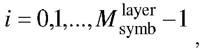

- The method according to claim 11, further comprising:
receiving quasi-co-location, QCL, group information of the one or more DMRS ports notified by a network side. - The method according to claim 12, wherein when there is only one QCL group or CDM group, P0 <P1 <, ..., Pv-1.
- The method according to claim 12, wherein when there are a plurality of QCL groups or CDM groups, the signal vector formed by the v number of DMRS ports is determined according to an ordering result of the serial numbers of the v number of DMRS ports.
- The method according to claim 14, wherein the ordering result is obtained by:ordering serial numbers of DMRS ports in each DMRS port subset to obtain an ordering result of the DMRS port serial numbers corresponding to the each DMRS port subset; andperforming ordering between DMRS port subsets based on the ordering result of the DMRS port serial numbers corresponding to the each DMRS port subset;wherein the each DMRS port subset is a set formed by DMRS ports included in a CDM group or QCL group.
- The method according to claim 15, wherein ordering between DMRS port subsets is performed by:performing ordering between DMRS port subsets based on a smallest DMRS port serial number in the each DMRS port subset; orperforming ordering between DMRS port subsets based on a serial number of the CDM group or QCL group corresponding to the each DMRS port subset; orperforming ordering between DMRS port subsets based on the number of DMRS ports included in the each DMRS port subset.
- The method according to claim 12, wherein the QCL group information specifically comprises one of following information:in a DMRS pattern, an identifier corresponding to a reference signal having a QCL relationship with each code division multiplexing, CDM, group, wherein DMRS ports included in a CDM group having the same identifier form a same QCL group, and identifiers corresponding to DMRS ports of different QCL groups are different, and identifiers corresponding to DMRS ports of the same QCL group are same;a CDM group included in a QCL group; anda list of DMRS ports included in a QCL group.
- The method according to claim 12, wherein the notification is received in a broadcast, multicast, or terminal-specific manner, and the QCL group information of the one or more DMRS ports is acquired from radio resource control, RRC, configuration or a media access control, MAC, control element, CE, or downlink control information, DCI, in the notification.
- A data transmission apparatus, comprising a memory and a processor, wherein the memory is configured to store program instructions, and the processor is configured to call the program instructions stored in the memory, and execute the following steps according to obtained programs:determining a preset demodulation reference signal, DMRS, port ordering rule; andmapping one or more data layers to one or more DMRS ports used in transmission according to the preset DMRS port ordering rule, and sending the one or more data layers to a terminal.
- The apparatus according to claim 19, wherein the processor mapping the one or more data layers to the one or more DMRS ports used in transmission according to the preset DMRS port ordering rule, and sending the one or more data layers to the terminal specifically comprises:based on a number v of multiple-input multiple-output, MIMO, parallel transmission data layers, arranging the one or more data layers into a following transmission signal vector according to serial numbers:
 determining a following signal vector formed by v number of DMRS ports:
 mapping the v number of data layers to the v number of DMRS ports according to a following formula, and sending the v number of data layers to the terminal:
 wherein,

- The apparatus according to claim 20, wherein the processor is further configured to:determine quasi-co-location, QCL, group information of the one or more DMRS ports; andnotify the terminal of the QCL group information.
- The apparatus according to claim 21, wherein when there is only one QCL group or CDM group, P0<P1<,...,Pv-1.
- The apparatus according to claim 21, wherein when there are a plurality of QCL groups or CDM groups, the signal vector formed by the v number of DMRS ports is determined according to an ordering result of the serial numbers of the v number of DMRS ports.
- The apparatus according to claim 23, wherein the ordering result is obtained by:ordering serial numbers of DMRS ports in each DMRS port subset to obtain an ordering result of the DMRS port serial numbers corresponding to the each DMRS port subset; andperforming ordering between DMRS port subsets based on the ordering result of the DMRS port serial numbers corresponding to the each DMRS port subset;wherein the each DMRS port subset is a set formed by DMRS ports included in a CDM group or QCL group.
- The apparatus according to claim 24, wherein ordering between DMRS port subsets is performed by:performing ordering between DMRS port subsets based on a smallest DMRS port serial number in the each DMRS port subset; orperforming ordering between DMRS port subsets based on a serial number of the CDM group or QCL group corresponding to the each DMRS port subset; orperforming ordering between DMRS port subsets based on the number of DMRS ports included in the each DMRS port subset.
- The apparatus according to claim 21, wherein the QCL group information specifically comprises one of following information:in a DMRS pattern, an identifier corresponding to a reference signal having a QCL relationship with each code division multiplexing, CDM, group, wherein DMRS ports included in CDM groups having the same identifier form a same QCL group, and identifiers corresponding to DMRS ports of different QCL groups are different, and identifiers corresponding to DMRS ports of a same QCL group are same;a CDM group included in a QCL group; anda list of DMRS ports included in a QCL group.
- The apparatus according to claim 21, wherein the processor notifies the QCL group information of the one or more DMRS ports to the terminal in a broadcast, multicast or terminal-specific manner, through radio resource control, RRC, configuration or a media access control, MAC, control element, CE, or downlink control information, DCI.
- A data receiving apparatus, comprising: a memory and a processor, wherein the memory is configured to store program instructions, and the processor is configured to call the program instructions stored in the memory, and execute following steps according to obtained programs:determining a preset demodulation reference signal, DMRS, port ordering rule; andreceiving one or more transmitted data layers mapped to one or more DMRS ports according to the preset DMRS port ordering rule.
- The apparatus according to claim 28, wherein the receiving one or more transmitted data layers mapped to one or more DMRS ports according to the preset DMRS port ordering rule specifically comprises:based on a number v of multiple-input multiple-output, MIMO, parallel transmission data layers, arranging the one or more data layers into a following transmission signal vector according to serial numbers:
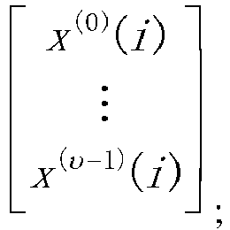 determining a following signal vector formed by v number of DMRS ports:
 receiving the one or more transmitted data layers mapped to the one or more DMRS ports used in transmission, according to a following formula:
 wherein,

- The apparatus according to claim 29, wherein the processor is further configured to receive quasi-co-location, QCL, group information of the one or more DMRS ports notified by a network side.
- The apparatus according to claim 30, wherein when there is only one QCL group or CDM group, P0<P1<,...,Pv-1.
- The apparatus according to claim 30, wherein when there are a plurality of QCL groups or CDM groups, the signal vector formed by the v number of DMRS ports is determined according to an ordering result of the serial numbers of the v number of DMRS ports.
- The apparatus according to claim 32, wherein the ordering result is obtained by:ordering serial numbers of DMRS ports in each DMRS port subset to obtain an ordering result of the DMRS port serial numbers corresponding to the each DMRS port subset; andperforming ordering between DMRS port subsets based on the ordering result of the DMRS port serial numbers corresponding to the each DMRS port subset;wherein the each DMRS port subset is a set formed by DMRS ports included in a CDM group or QCL group.
- The apparatus according to claim 33, wherein the processor sorts the DMRS port subsets by:performing ordering between DMRS port subsets based on a smallest DMRS port serial number in the each DMRS port subset; orperforming ordering between DMRS port subsets based on a serial number of the CDM group or QCL group corresponding to the each DMRS port subset; orperforming ordering between DMRS port subsets based on the number of DMRS ports included in the each DMRS port subset.
- The apparatus according to claim 30, wherein the QCL group information specifically comprises one of following information:in a DMRS pattern, an identifier corresponding to a reference signal having a QCL relationship with each code division multiplexing, CDM, group, wherein DMRS ports included in CDM groups having the same identifier form a same QCL group, and identifiers corresponding to DMRS ports of different QCL groups are different, and identifiers corresponding to DMRS ports of the same QCL group are same;a CDM group included in a QCL group; anda list of DMRS ports included in a QCL group.
- The apparatus according to claim 30, wherein the processor receives the notification in a broadcast, multicast, or terminal-specific manner, and acquires the QCL group information of the one or more DMRS ports from radio resource control, RRC, configuration or a media access control, MAC, control element, CE, or downlink control information, DCI, in the notification.
- A data sending apparatus, comprising:a determining unit configured to determine a preset demodulation reference signal, DMRS, port ordering rule; anda sending unit configured to map one or more data layers to one or more DMRS ports used in transmission according to the preset DMRS port ordering rule, and send the one or more data layers to a terminal.
- A data receiving apparatus, comprising:a determining unit configured to determine a preset demodulation reference signal, DMRS, port ordering rule; anda receiving unit configured to receive one or more sent data layer mapped to one or more DMRS ports according to the preset DMRS port ordering rule.
- A computer storage medium, storing computer-executable instructions, which are used for causing a computer to execute a method according to any one of claims 1 to 18.
Applications Claiming Priority (2)
| Application Number | Priority Date | Filing Date | Title |
|---|---|---|---|
| CN201711192554.6A CN109842468B (en) | 2017-11-24 | 2017-11-24 | Data transmission method and device and computer storage medium |
| PCT/CN2018/109895 WO2019100859A1 (en) | 2017-11-24 | 2018-10-11 | Data transmission method and apparatus, and computer storage medium |
Publications (3)
| Publication Number | Publication Date |
|---|---|
| EP3716708A1 true EP3716708A1 (en) | 2020-09-30 |
| EP3716708A4 EP3716708A4 (en) | 2021-01-13 |
| EP3716708B1 EP3716708B1 (en) | 2025-01-08 |
Family
ID=66631798
Family Applications (1)
| Application Number | Title | Priority Date | Filing Date |
|---|---|---|---|
| EP18882179.7A Active EP3716708B1 (en) | 2017-11-24 | 2018-10-11 | Data transmission method and apparatus, and computer storage medium |
Country Status (6)
| Country | Link |
|---|---|
| US (1) | US11528120B2 (en) |
| EP (1) | EP3716708B1 (en) |
| JP (1) | JP2021505022A (en) |
| KR (1) | KR20200088455A (en) |
| CN (1) | CN109842468B (en) |
| WO (1) | WO2019100859A1 (en) |
Families Citing this family (8)
| Publication number | Priority date | Publication date | Assignee | Title |
|---|---|---|---|---|
| EP3905581A1 (en) * | 2017-03-24 | 2021-11-03 | Apple Inc. | Dm-rs grouping and csi reporting for comp |
| CN110034890B (en) | 2018-01-12 | 2020-07-10 | 电信科学技术研究院有限公司 | Data transmission method and device and computer storage medium |
| CN111435883B (en) * | 2019-01-11 | 2021-10-26 | 华为技术有限公司 | Quasi co-location indication method and device |
| US11240836B2 (en) * | 2019-08-08 | 2022-02-01 | Qualcomm Incorproated | Multi-state reference signaling and single-state data techniques |
| WO2023003290A1 (en) * | 2021-07-20 | 2023-01-26 | 엘지전자 주식회사 | Method and device for uplink or downlink transmission/reception in wireless communication system |
| CN118575435A (en) * | 2022-01-26 | 2024-08-30 | 高通股份有限公司 | Downlink scheduling for increased orthogonal DMRS ports and PRB bundling sizes |
| MX2024005509A (en) * | 2022-01-28 | 2024-05-23 | Zte Corp | Systems and methods for dmrs port configuration and indication. |
| WO2024205033A1 (en) * | 2023-03-24 | 2024-10-03 | Samsung Electronics Co., Ltd. | Apparatus and methods for indicating dmrs ports for user equipment in a wireless communication system |
Family Cites Families (13)
| Publication number | Priority date | Publication date | Assignee | Title |
|---|---|---|---|---|
| WO2011085509A1 (en) | 2010-01-12 | 2011-07-21 | Telefonaktiebolaget L M Ericsson (Publ) | Layer-to dm rs port mapping for lte-advanced |
| KR101740221B1 (en) | 2010-01-18 | 2017-05-29 | 주식회사 골드피크이노베이션즈 | Method and Apparatus for allocating Channel State Information-Reference Signal in wireless communication system |
| KR101789621B1 (en) * | 2010-01-19 | 2017-10-25 | 엘지전자 주식회사 | A method and a base station for transmitting uplink data, and a method and a user equipment for receiving uplink data |
| RU2548899C2 (en) * | 2010-01-20 | 2015-04-20 | Телефонактиеболагет Лм Эрикссон (Пабл) | Antenna port mapping method and device for demodulating reference signals |
| CN102158319B (en) * | 2010-02-12 | 2015-12-16 | 中兴通讯股份有限公司 | A kind of method for precoding based on hybrid multiplex demodulation reference mark and device |
| CN102299769B (en) * | 2011-09-01 | 2014-06-25 | 电信科学技术研究院 | Downlink control information transmission method and device |
| EP3232598B1 (en) * | 2012-03-12 | 2019-09-18 | Samsung Electronics Co., Ltd. | Method and apparatus for transmitting/receiving control channel in wireless communication system |
| CN104079384B (en) | 2013-03-27 | 2017-10-17 | 华为技术有限公司 | The data transmission method and equipment of multiaerial system |
| CN104579595A (en) * | 2013-10-16 | 2015-04-29 | 中兴通讯股份有限公司 | ePHICH (enhanced physical HARQ (hybrid automatic repeat request) indicator channel) sending and receiving methods and system |
| CN107078874B (en) * | 2014-09-24 | 2020-09-04 | Lg 电子株式会社 | Method for transmitting and receiving reference signal in wireless communication system and apparatus therefor |
| CN106712915B (en) * | 2015-11-16 | 2020-06-30 | 中国移动通信集团公司 | A method, apparatus, base station and terminal for sending demodulation reference signal |
| CN107306177B (en) * | 2016-04-22 | 2023-11-10 | 华为技术有限公司 | Methods of transmitting data, user equipment and network side equipment |
| CN107889258B (en) * | 2016-09-30 | 2020-07-24 | 华为技术有限公司 | Method and device for obtaining and delivering DMRS port configuration information |
-
2017
- 2017-11-24 CN CN201711192554.6A patent/CN109842468B/en active Active
-
2018
- 2018-10-11 KR KR1020207018236A patent/KR20200088455A/en not_active Ceased
- 2018-10-11 JP JP2020528299A patent/JP2021505022A/en active Pending
- 2018-10-11 US US16/766,700 patent/US11528120B2/en active Active
- 2018-10-11 EP EP18882179.7A patent/EP3716708B1/en active Active
- 2018-10-11 WO PCT/CN2018/109895 patent/WO2019100859A1/en not_active Ceased
Also Published As
| Publication number | Publication date |
|---|---|
| EP3716708A4 (en) | 2021-01-13 |
| US20200287699A1 (en) | 2020-09-10 |
| CN109842468A (en) | 2019-06-04 |
| CN109842468B (en) | 2020-09-01 |
| EP3716708B1 (en) | 2025-01-08 |
| WO2019100859A1 (en) | 2019-05-31 |
| JP2021505022A (en) | 2021-02-15 |
| US11528120B2 (en) | 2022-12-13 |
| KR20200088455A (en) | 2020-07-22 |
Similar Documents
| Publication | Publication Date | Title |
|---|---|---|
| US11528120B2 (en) | Data transmission method and apparatus, and computer storage medium | |
| CN116346299B (en) | Reference signal configuration information indication method, base station and terminal | |
| EP3576334A1 (en) | Method for transmitting dmrs, and communication device | |
| US11916628B2 (en) | Method and apparatus for providing antenna port indication to user equipment | |
| EP3691381A1 (en) | Method and apparatus for transmitting downlink control information, and method and apparatus for obtaining number of blind detections | |
| CN109802807B (en) | Information indication, resource determination method and device, and computer storage medium | |
| CN108632001A (en) | A reference signal sending method, receiving method and device | |
| US20190349181A1 (en) | Communication method and network device | |
| US11342966B2 (en) | Information indicating and determining method and apparatus, and computer storage medium | |
| JP7481454B2 (en) | Method for reference signal construction - Patents.com | |
| CN109842469B (en) | Information indication, determination method and device, computer storage medium | |
| TWI744585B (en) | Data transmission method and device, computer storage medium | |
| EP4465573A1 (en) | Dmrs transmission method and apparatus, and storage medium |
Legal Events
| Date | Code | Title | Description |
|---|---|---|---|
| STAA | Information on the status of an ep patent application or granted ep patent |
Free format text: STATUS: THE INTERNATIONAL PUBLICATION HAS BEEN MADE |
|
| PUAI | Public reference made under article 153(3) epc to a published international application that has entered the european phase |
Free format text: ORIGINAL CODE: 0009012 |
|
| STAA | Information on the status of an ep patent application or granted ep patent |
Free format text: STATUS: REQUEST FOR EXAMINATION WAS MADE |
|
| 17P | Request for examination filed |
Effective date: 20200604 |
|
| AK | Designated contracting states |
Kind code of ref document: A1 Designated state(s): AL AT BE BG CH CY CZ DE DK EE ES FI FR GB GR HR HU IE IS IT LI LT LU LV MC MK MT NL NO PL PT RO RS SE SI SK SM TR |
|
| AX | Request for extension of the european patent |
Extension state: BA ME |
|
| A4 | Supplementary search report drawn up and despatched |
Effective date: 20201211 |
|
| RIC1 | Information provided on ipc code assigned before grant |
Ipc: H04W 72/04 20090101AFI20201207BHEP Ipc: H04L 1/18 20060101ALI20201207BHEP Ipc: H04L 5/00 20060101ALI20201207BHEP |
|
| DAV | Request for validation of the european patent (deleted) | ||
| DAX | Request for extension of the european patent (deleted) | ||
| RAP1 | Party data changed (applicant data changed or rights of an application transferred) |
Owner name: DATANG MOBILE COMMUNICATIONS EQUIPMENT CO., LTD. |
|
| STAA | Information on the status of an ep patent application or granted ep patent |
Free format text: STATUS: EXAMINATION IS IN PROGRESS |
|
| 17Q | First examination report despatched |
Effective date: 20221219 |
|
| GRAP | Despatch of communication of intention to grant a patent |
Free format text: ORIGINAL CODE: EPIDOSNIGR1 |
|
| STAA | Information on the status of an ep patent application or granted ep patent |
Free format text: STATUS: GRANT OF PATENT IS INTENDED |
|
| INTG | Intention to grant announced |
Effective date: 20240731 |
|
| GRAS | Grant fee paid |
Free format text: ORIGINAL CODE: EPIDOSNIGR3 |
|
| GRAA | (expected) grant |
Free format text: ORIGINAL CODE: 0009210 |
|
| STAA | Information on the status of an ep patent application or granted ep patent |
Free format text: STATUS: THE PATENT HAS BEEN GRANTED |
|
| AK | Designated contracting states |
Kind code of ref document: B1 Designated state(s): AL AT BE BG CH CY CZ DE DK EE ES FI FR GB GR HR HU IE IS IT LI LT LU LV MC MK MT NL NO PL PT RO RS SE SI SK SM TR |
|
| REG | Reference to a national code |
Ref country code: GB Ref legal event code: FG4D |
|
| REG | Reference to a national code |
Ref country code: CH Ref legal event code: EP |
|
| REG | Reference to a national code |
Ref country code: DE Ref legal event code: R096 Ref document number: 602018078433 Country of ref document: DE |
|
| REG | Reference to a national code |
Ref country code: IE Ref legal event code: FG4D |
|
| REG | Reference to a national code |
Ref country code: LT Ref legal event code: MG9D |
|
| REG | Reference to a national code |
Ref country code: NL Ref legal event code: MP Effective date: 20250108 |
|
| REG | Reference to a national code |
Ref country code: AT Ref legal event code: MK05 Ref document number: 1759141 Country of ref document: AT Kind code of ref document: T Effective date: 20250108 |
|
| PG25 | Lapsed in a contracting state [announced via postgrant information from national office to epo] |
Ref country code: NL Free format text: LAPSE BECAUSE OF FAILURE TO SUBMIT A TRANSLATION OF THE DESCRIPTION OR TO PAY THE FEE WITHIN THE PRESCRIBED TIME-LIMIT Effective date: 20250108 |
|
| PG25 | Lapsed in a contracting state [announced via postgrant information from national office to epo] |
Ref country code: RS Free format text: LAPSE BECAUSE OF FAILURE TO SUBMIT A TRANSLATION OF THE DESCRIPTION OR TO PAY THE FEE WITHIN THE PRESCRIBED TIME-LIMIT Effective date: 20250408 |
|
| PG25 | Lapsed in a contracting state [announced via postgrant information from national office to epo] |
Ref country code: FI Free format text: LAPSE BECAUSE OF FAILURE TO SUBMIT A TRANSLATION OF THE DESCRIPTION OR TO PAY THE FEE WITHIN THE PRESCRIBED TIME-LIMIT Effective date: 20250108 |
|
| PG25 | Lapsed in a contracting state [announced via postgrant information from national office to epo] |
Ref country code: PL Free format text: LAPSE BECAUSE OF FAILURE TO SUBMIT A TRANSLATION OF THE DESCRIPTION OR TO PAY THE FEE WITHIN THE PRESCRIBED TIME-LIMIT Effective date: 20250108 |
|
| PG25 | Lapsed in a contracting state [announced via postgrant information from national office to epo] |
Ref country code: ES Free format text: LAPSE BECAUSE OF FAILURE TO SUBMIT A TRANSLATION OF THE DESCRIPTION OR TO PAY THE FEE WITHIN THE PRESCRIBED TIME-LIMIT Effective date: 20250108 |
|
| PG25 | Lapsed in a contracting state [announced via postgrant information from national office to epo] |
Ref country code: IS Free format text: LAPSE BECAUSE OF FAILURE TO SUBMIT A TRANSLATION OF THE DESCRIPTION OR TO PAY THE FEE WITHIN THE PRESCRIBED TIME-LIMIT Effective date: 20250508 Ref country code: NO Free format text: LAPSE BECAUSE OF FAILURE TO SUBMIT A TRANSLATION OF THE DESCRIPTION OR TO PAY THE FEE WITHIN THE PRESCRIBED TIME-LIMIT Effective date: 20250408 |
|
| PG25 | Lapsed in a contracting state [announced via postgrant information from national office to epo] |
Ref country code: HR Free format text: LAPSE BECAUSE OF FAILURE TO SUBMIT A TRANSLATION OF THE DESCRIPTION OR TO PAY THE FEE WITHIN THE PRESCRIBED TIME-LIMIT Effective date: 20250108 |
|
| PG25 | Lapsed in a contracting state [announced via postgrant information from national office to epo] |
Ref country code: LV Free format text: LAPSE BECAUSE OF FAILURE TO SUBMIT A TRANSLATION OF THE DESCRIPTION OR TO PAY THE FEE WITHIN THE PRESCRIBED TIME-LIMIT Effective date: 20250108 Ref country code: PT Free format text: LAPSE BECAUSE OF FAILURE TO SUBMIT A TRANSLATION OF THE DESCRIPTION OR TO PAY THE FEE WITHIN THE PRESCRIBED TIME-LIMIT Effective date: 20250508 |
|
| PG25 | Lapsed in a contracting state [announced via postgrant information from national office to epo] |
Ref country code: GR Free format text: LAPSE BECAUSE OF FAILURE TO SUBMIT A TRANSLATION OF THE DESCRIPTION OR TO PAY THE FEE WITHIN THE PRESCRIBED TIME-LIMIT Effective date: 20250409 Ref country code: BG Free format text: LAPSE BECAUSE OF FAILURE TO SUBMIT A TRANSLATION OF THE DESCRIPTION OR TO PAY THE FEE WITHIN THE PRESCRIBED TIME-LIMIT Effective date: 20250108 |
|
| PG25 | Lapsed in a contracting state [announced via postgrant information from national office to epo] |
Ref country code: AT Free format text: LAPSE BECAUSE OF FAILURE TO SUBMIT A TRANSLATION OF THE DESCRIPTION OR TO PAY THE FEE WITHIN THE PRESCRIBED TIME-LIMIT Effective date: 20250108 |
|
| PG25 | Lapsed in a contracting state [announced via postgrant information from national office to epo] |
Ref country code: SE Free format text: LAPSE BECAUSE OF FAILURE TO SUBMIT A TRANSLATION OF THE DESCRIPTION OR TO PAY THE FEE WITHIN THE PRESCRIBED TIME-LIMIT Effective date: 20250108 |
|
| PG25 | Lapsed in a contracting state [announced via postgrant information from national office to epo] |
Ref country code: SM Free format text: LAPSE BECAUSE OF FAILURE TO SUBMIT A TRANSLATION OF THE DESCRIPTION OR TO PAY THE FEE WITHIN THE PRESCRIBED TIME-LIMIT Effective date: 20250108 |
|
| REG | Reference to a national code |
Ref country code: DE Ref legal event code: R097 Ref document number: 602018078433 Country of ref document: DE |
|
| PG25 | Lapsed in a contracting state [announced via postgrant information from national office to epo] |
Ref country code: DK Free format text: LAPSE BECAUSE OF FAILURE TO SUBMIT A TRANSLATION OF THE DESCRIPTION OR TO PAY THE FEE WITHIN THE PRESCRIBED TIME-LIMIT Effective date: 20250108 |
|
| PG25 | Lapsed in a contracting state [announced via postgrant information from national office to epo] |
Ref country code: CZ Free format text: LAPSE BECAUSE OF FAILURE TO SUBMIT A TRANSLATION OF THE DESCRIPTION OR TO PAY THE FEE WITHIN THE PRESCRIBED TIME-LIMIT Effective date: 20250108 Ref country code: EE Free format text: LAPSE BECAUSE OF FAILURE TO SUBMIT A TRANSLATION OF THE DESCRIPTION OR TO PAY THE FEE WITHIN THE PRESCRIBED TIME-LIMIT Effective date: 20250108 |
|
| PG25 | Lapsed in a contracting state [announced via postgrant information from national office to epo] |
Ref country code: RO Free format text: LAPSE BECAUSE OF FAILURE TO SUBMIT A TRANSLATION OF THE DESCRIPTION OR TO PAY THE FEE WITHIN THE PRESCRIBED TIME-LIMIT Effective date: 20250108 |
|
| PG25 | Lapsed in a contracting state [announced via postgrant information from national office to epo] |
Ref country code: SK Free format text: LAPSE BECAUSE OF FAILURE TO SUBMIT A TRANSLATION OF THE DESCRIPTION OR TO PAY THE FEE WITHIN THE PRESCRIBED TIME-LIMIT Effective date: 20250108 |
|
| PLBE | No opposition filed within time limit |
Free format text: ORIGINAL CODE: 0009261 |
|
| STAA | Information on the status of an ep patent application or granted ep patent |
Free format text: STATUS: NO OPPOSITION FILED WITHIN TIME LIMIT |
|
| 26N | No opposition filed |
Effective date: 20251009 |
|
| PGFP | Annual fee paid to national office [announced via postgrant information from national office to epo] |
Ref country code: DE Payment date: 20251021 Year of fee payment: 8 |
|
| PGFP | Annual fee paid to national office [announced via postgrant information from national office to epo] |
Ref country code: GB Payment date: 20251022 Year of fee payment: 8 |
|
| PGFP | Annual fee paid to national office [announced via postgrant information from national office to epo] |
Ref country code: FR Payment date: 20251030 Year of fee payment: 8 |
|
| PG25 | Lapsed in a contracting state [announced via postgrant information from national office to epo] |
Ref country code: IT Free format text: LAPSE BECAUSE OF FAILURE TO SUBMIT A TRANSLATION OF THE DESCRIPTION OR TO PAY THE FEE WITHIN THE PRESCRIBED TIME-LIMIT Effective date: 20250108 |