EP3716617A1 - Image processing apparatus, image capturing apparatus, image processing method, and storage medium - Google Patents
Image processing apparatus, image capturing apparatus, image processing method, and storage medium Download PDFInfo
- Publication number
- EP3716617A1 EP3716617A1 EP20162320.4A EP20162320A EP3716617A1 EP 3716617 A1 EP3716617 A1 EP 3716617A1 EP 20162320 A EP20162320 A EP 20162320A EP 3716617 A1 EP3716617 A1 EP 3716617A1
- Authority
- EP
- European Patent Office
- Prior art keywords
- noise
- image
- color
- color difference
- luminance
- Prior art date
- Legal status (The legal status is an assumption and is not a legal conclusion. Google has not performed a legal analysis and makes no representation as to the accuracy of the status listed.)
- Granted
Links
Images





Classifications
-
- H—ELECTRICITY
- H04—ELECTRIC COMMUNICATION TECHNIQUE
- H04N—PICTORIAL COMMUNICATION, e.g. TELEVISION
- H04N9/00—Details of colour television systems
- H04N9/64—Circuits for processing colour signals
- H04N9/646—Circuits for processing colour signals for image enhancement, e.g. vertical detail restoration, cross-colour elimination, contour correction, chrominance trapping filters
-
- H—ELECTRICITY
- H04—ELECTRIC COMMUNICATION TECHNIQUE
- H04N—PICTORIAL COMMUNICATION, e.g. TELEVISION
- H04N23/00—Cameras or camera modules comprising electronic image sensors; Control thereof
- H04N23/80—Camera processing pipelines; Components thereof
- H04N23/81—Camera processing pipelines; Components thereof for suppressing or minimising disturbance in the image signal generation
-
- H—ELECTRICITY
- H04—ELECTRIC COMMUNICATION TECHNIQUE
- H04N—PICTORIAL COMMUNICATION, e.g. TELEVISION
- H04N23/00—Cameras or camera modules comprising electronic image sensors; Control thereof
- H04N23/80—Camera processing pipelines; Components thereof
- H04N23/84—Camera processing pipelines; Components thereof for processing colour signals
- H04N23/88—Camera processing pipelines; Components thereof for processing colour signals for colour balance, e.g. white-balance circuits or colour temperature control
-
- H—ELECTRICITY
- H04—ELECTRIC COMMUNICATION TECHNIQUE
- H04N—PICTORIAL COMMUNICATION, e.g. TELEVISION
- H04N25/00—Circuitry of solid-state image sensors [SSIS]; Control thereof
- H04N25/10—Circuitry of solid-state image sensors [SSIS]; Control thereof for transforming different wavelengths into image signals
- H04N25/11—Arrangement of colour filter arrays [CFA]; Filter mosaics
- H04N25/13—Arrangement of colour filter arrays [CFA]; Filter mosaics characterised by the spectral characteristics of the filter elements
- H04N25/134—Arrangement of colour filter arrays [CFA]; Filter mosaics characterised by the spectral characteristics of the filter elements based on three different wavelength filter elements
-
- H—ELECTRICITY
- H04—ELECTRIC COMMUNICATION TECHNIQUE
- H04N—PICTORIAL COMMUNICATION, e.g. TELEVISION
- H04N25/00—Circuitry of solid-state image sensors [SSIS]; Control thereof
- H04N25/60—Noise processing, e.g. detecting, correcting, reducing or removing noise
- H04N25/61—Noise processing, e.g. detecting, correcting, reducing or removing noise the noise originating only from the lens unit, e.g. flare, shading, vignetting or "cos4"
-
- H—ELECTRICITY
- H04—ELECTRIC COMMUNICATION TECHNIQUE
- H04N—PICTORIAL COMMUNICATION, e.g. TELEVISION
- H04N9/00—Details of colour television systems
- H04N9/79—Processing of colour television signals in connection with recording
- H04N9/7908—Suppression of interfering signals at the reproducing side, e.g. noise
Definitions
- the present invention relates to an image processing apparatus, an image capturing apparatus, an image processing method, and a storage medium.
- controls such as control for suppressing noise caused by gain, temperature, exposure time and the like and control of white balance (WB) correction are performed.
- WB white balance
- Japanese Patent No. 3762725 discloses inferring and suppressing the noise component within a video signal obtained by an image sensor, based on shooting conditions such as gain and exposure time determined based on photometric values, in the case of displaying the video signal.
- Japanese Patent Laid-Open No. 2013-162248 discloses a technology for suppressing color noise in particular, out of the noise component that occurs. Specifically, deriving the noise level which changes according to exposure time and temperature, calculating the level of color shift corresponding to the derived noise level, and implementing processing for suppressing the color component based on gain is disclosed.
- Coloring caused by noise that occurs in low luminance regions changes greatly according to the shooting conditions, particularly, the gain of white balance correction (white balance gain). Coloring caused by noise is also affected by the white balance gain in regions other than low luminance regions.
- the conventional technologies do not take the influence exerted by white balance correction on coloring caused by a noise into consideration.
- the present invention has been made in view of such circumstances, and provides a technology for performing processing for suppressing the color component of a captured image with consideration for the influence exerted by white balance correction on coloring caused by noise.
- the present invention in its first aspect provides an image processing apparatus as specified in claims 1-8.
- the present invention in its second aspect provides an image capturing apparatus as specified in claim 9.
- the present invention in its third aspect provides an image processing method as specified in claim 10.
- the present invention in its fourth aspect provides a storage medium as specified in claim 11.
- FIG. 1 is a block diagram showing a configuration of an image capturing apparatus 100 that includes an image processing apparatus.
- light that enters through a lens 10 forms an image on a light receiving surface of an image sensor 20 that is typified by a CCD or CMOS sensor.
- the image sensor 20 converts the light forming the image into an image signal through photoelectric conversion and outputs the image signal.
- An image processing unit 30 performs various types of image processing such as color conversion, AE processing, white balance correction (WB correction), and gamma processing for performing tone conversion on the image signal output by the image sensor 20.
- a system control unit 40 includes a ROM in which a control program is stored and a RAM that is used as a work memory, and performs overall control of the image capturing apparatus 100 by executing the control program.
- a gain control unit 31 determines the gain to be applied to the image signal generated through photoelectric conversion by the image sensor 20, and applies the determined gain to the image signal.
- An exposure time control unit 32 determines the exposure time, and performs exposure time control on the image sensor 20.
- a noise level estimation unit 33 estimates the level (noise level) of noise that is included in the captured image, based on the gain determined by the gain control unit 31. Note that the noise level is affected by various shooting conditions including gain. Exposure time is given as an example of a shooting condition that affects the noise level. Accordingly, the noise level estimation unit 33 may estimate the noise level based on the exposure time determined by the exposure time control unit 32, in addition to the gain determined by the gain control unit 31.
- a WB gain control unit 34 determines the gain (white balance gain) for each color of the image signal, such that an appropriate white balance is obtained in the image signal. That is, the gain of the gain control unit 31 is common to all colors, whereas the white balance gain (WB gain) is determined for each color.
- the WB gain control unit 34 performs signal processing (WB correction) for applying the WB gain determined for each color to the image signal.
- a noise luminance/color difference estimation unit 35 estimates the luminance component and color difference component of noise (noise included in the captured image) that is actually output, by applying the color-specific WB gains determined by the WB gain control unit 34 to the noise level estimated by the noise level estimation unit 33.
- a color suppression range determination unit 36 determines a luminance range for applying processing for suppressing the color component (color suppression processing), based on the luminance component of noise estimated by the noise luminance/color difference estimation unit 35.
- a color suppression level determination unit 37 determines the strength of color suppression processing, based on the color difference component of noise estimated by the noise luminance/color difference estimation unit 35.
- a color suppression unit 38 applies color suppression processing at the strength determined by the color suppression level determination unit 37 to pixels having a luminance within the luminance range determined by the color suppression range determination unit 36, out of the pixels of the captured image that has undergone white balance correction.
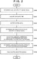
- FIG. 2 is a flowchart of image processing according to the first embodiment. The processing of this flowchart starts when an image signal generated through photoelectric conversion by the image sensor 20 is input to the image processing unit 30.
- step S10 the gain control unit 31 determines a gain common to all colors, and applies the determined gain to the image signal.
- the exposure time control unit 32 acquires the exposure time of the image signal.
- step S12 the noise level estimation unit 33 estimates the noise level based on the gain determined in step S10. Note that the noise level estimation unit 33 may estimate the noise level based on the exposure time acquired in step S11, in addition to the gain determined in step S10.
- FIG. 3 is a conceptual diagram of processing for estimating the noise level. As shown in FIG. 3 , the noise level corresponding to the gain and exposure time is estimated.
- the WB gain control unit 34 determines the WB gain for each color of the image signal, and applies the determined WB gains to the image signal.
- the noise luminance/color difference estimation unit 35 calculates a noise signal estimation value for each color based on the noise level and the WB gains. The noise luminance/color difference estimation unit 35 then calculates an estimated noise luminance value (luminance component of noise) and an estimated noise color difference value (color difference component of noise) from the calculated color-specific noise signal estimation values.
- FIG. 4 is a conceptual diagram of processing for calculating the color-specific noise signal estimation values.
- the noise that occurs in the image signal that is generated by the image sensor 20 is an electrical signal, and the gain of the gain control unit 31 is common to all colors.
- WB gain is determined for each color.
- the noise signal estimation value may differ for every color, and coloring of noise may occur.
- the noise luminance/color difference estimation unit 35 calculates the luminance component and color difference component of noise from such color-specific noise signal estimation values.
- the noise level is estimated based on the gain of the gain control unit 31, and the luminance component and color difference component of noise are calculated based on the noise level and WB gains. Accordingly, as the overall processing of steps S12 and S14, the luminance component and color difference component of noise that are included in the captured image that has undergone white balance correction are estimated based on the gain common to all colors and the WB gain determined for each color.
- the color suppression range determination unit 36 determines the luminance range for applying color suppression processing, based on the size of the luminance component of noise. Also, the color suppression level determination unit 37 determines the strength of color suppression processing, based on the size of the color difference component of noise.
- FIG. 5 is a conceptual diagram of processing for determining the luminance range for applying color suppression processing.
- a range of luminance less than or equal to the estimated noise luminance (range of luminance less than or equal to the size of the luminance component of noise) is determined as the luminance range for applying color suppression processing.
- the luminance range for applying color suppression processing may be a range of luminance less than the estimated noise luminance (range of luminance less than the size of the luminance component of noise).
- FIG. 6 is a conceptual diagram of a size ⁇ CrCb of the color difference component of noise.
- ⁇ CrCb is calculated in accordance with the following equation (1).
- ⁇ CrCb ⁇ Cr 2 + Cb 2
- Cr and Cb are estimated noise color difference values (color difference component of noise) calculated by the noise luminance/color difference estimation unit 35 in step S14.
- the degree of coloring caused by noise can be determined, by deriving the size ⁇ CrCb of the color difference component of noise.
- FIG. 7 is a conceptual diagram of processing for determining the strength of color suppression processing. As shown in FIG. 7 , the strength of color suppression processing changes, according to the size ⁇ CrCb of the color difference component of noise.
- the color suppression unit 38 in step S16, applies color suppression processing to the captured image that has undergone WB correction.
- Color suppression processing is performed at the strength determined in step S15 on pixels having a luminance within the luminance range determined in step S15, out of the pixels of the captured image.
- the image capturing apparatus 100 acquires a captured image, by applying the gain common to all colors and the WB gain determined for each color to an image signal that is generated through photoelectric conversion by the image sensor 20 (steps S10 and S13 of FIG. 2 ).
- the image capturing apparatus 100 estimates the luminance component and color difference component of noise included in the captured image, based on the gain common to all colors and the WB gain determined for each color (steps S12 and S14 of FIG. 2 ).
- the image capturing apparatus 100 determines the luminance range for applying color suppression processing, based on the size of the luminance component of noise, and determines the strength of color suppression processing, based on the size of the color difference component of noise.
- the image capturing apparatus 100 then applies color suppression processing at the determined strength to pixels having a luminance within the determined luminance range, out of the pixels of the captured image. It thereby becomes possible to perform processing for suppressing the color component of a captured image with consideration for the influence exerted by WB correction on coloring caused by noise.
- the image capturing apparatus 100 may be configured to not determine a luminance range for applying color suppression processing, and to apply color suppression processing to a captured image regardless of luminance.
- color suppression processing is also applied to high luminance regions in which coloring caused by noise is not that noticeable, the influence exerted by WB correction on coloring caused by noise is still being taken into consideration in color suppression processing.
- the strength of color suppression processing is also higher as the size of the color difference component of noise increases
- the specific relationship between the size of the color difference component of noise and the strength of color suppression processing is not particularly limited. As long as the strength of color suppression processing is determined based on the size of the color difference component of noise, the influence exerted by WB correction on coloring caused by noise is still being taken into consideration in color suppression processing.
- a second embodiment describes a configuration for determining a color difference range for applying color suppression processing, and applying color suppression processing to pixels having a color difference within the determined color difference range, out of the pixels of the captured image.
- the basic configuration of the image capturing apparatus 100 is similar to the first embodiment (refer to FIG. 1 ).
- description will focus on the differences from the first embodiment.
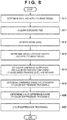
- FIG. 8 is a flowchart of image processing according to the second embodiment.
- the same reference signs as FIG. 2 are given to steps in which the same or similar processing as FIG. 2 is performed, and description thereof will be omitted.
- the processing of this flowchart starts when an image signal generated through photoelectric conversion by the image sensor 20 is input to the image processing unit 30.
- step S26 the color suppression range determination unit 36 determines the color difference range for applying color suppression processing, based on the color difference component of noise calculated in step S14.
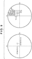
- FIG. 9 is a conceptual diagram of processing for determining the color difference range for applying color suppression processing.
- a range of color difference near the color difference component of noise is determined as the color difference range for applying color suppression processing.
- Near as referred to here is a range in which the possibility of the color difference of pixels of the captured image being caused by the color difference component of noise is considered to be high, and can, for example, be determined using threshold values ThCr and ThCb as shown in FIG. 9 . That is, in the example in FIG. 9 , the case where the color difference satisfies 0 ⁇ estimated Cr ⁇ estimated Cr + ThCr and 0 ⁇ estimated Cb ⁇ estimated Cb + ThCb is determined as the color difference range for applying color suppression processing.
- the color difference range for applying color suppression processing is not limited to a range of color difference near the color difference component of noise, as long as determination of the color difference range is based on the color difference component of noise.
- the color suppression unit 38 in step S27, applies color suppression processing to the captured image that has undergone WB correction.
- Color suppression processing is performed at the strength determined in step S15 on pixels having a luminance within the luminance range determined in step S15 and having a color difference within the color difference range determined in step S26, out of the pixels of the captured image.
- the image capturing apparatus 100 determines the color difference range for applying color suppression processing, based on the color difference component of noise included in a captured image that has undergone WB correction. The image capturing apparatus 100 then applies color suppression processing to pixels having a color difference within the determined color difference range, out of the pixels of the captured image. It thereby becomes possible to perform processing for suppressing the color component of a captured image with consideration for the influence exerted by WB correction on coloring caused by noise.
- the first embodiment described a configuration for estimating the luminance component and color difference component of noise that are included in a captured image, based on a gain common to all colors and a WB gain determined for each color.
- the method of estimating the luminance component and color difference component of noise is not limited to the method described in the first embodiment.
- a third embodiment describes a configuration for estimating the luminance component and color difference component of noise, based on the pixel values of a region of the captured image that corresponds to a shaded region, or the pixel values of a partial region of the captured image that is selected in accordance with a user instruction.
- FIG. 10 is a block diagram showing a configuration of an image capturing apparatus 200 that includes an image processing apparatus.
- the image capturing apparatus 200 differs in comparison to the image capturing apparatus 100 shown in FIG. 1 in being provided with an image processing unit 130 instead of the image processing unit 30.
- the image processing unit 130 differs in comparison to the image processing unit 30 in being provided with a noise estimation region selection unit 133 and a noise luminance/color difference estimation unit 135 instead of the noise level estimation unit 33 and the noise luminance/color difference estimation unit 35.
- description will focus on the differences from the first embodiment.
- the noise estimation region selection unit 133 selects a region (noise estimation region) for performing noise estimation in the captured image.
- the noise estimation region selection unit 133 may select a region corresponding to a shaded region of the image sensor 20 in the captured image, or may select a partial region of the captured image in accordance with a user instruction. In the case of the latter, the user instructs that a low luminance region in the captured image be selected.
- the noise luminance/color difference estimation unit 135 estimates the luminance component and color difference component of noise, based on the pixel values of the noise estimation region of the captured image.
- the noise luminance/color difference estimation unit 135 calculates luminance values and color difference values from the pixel values of the noise estimation region of the captured image, and uses the calculated luminance values and color difference values as estimation values of the luminance component and color difference component of noise.
- FIG. 11 is a conceptual diagram showing a shaded region and an unshaded region of the image sensor 20.
- the region (shaded region) other than the image circle does not receive light. Accordingly, it is possible to regard the pixel values of the region of the captured image that corresponds to the shaded region as noise, by selecting the shaded region as the noise estimation region.
- FIG. 12 is a flowchart of image processing according to the third embodiment.
- the same reference signs as FIG. 2 are given to steps in which the same or similar processing as FIG. 2 is performed, and description thereof will be omitted.
- the processing of this flowchart starts when an image signal generated through photoelectric conversion by the image sensor 20 is input to the image processing unit 130.
- the noise estimation region selection unit 133 selects a noise estimation region of the captured image.
- the noise estimation region selection unit 133 may select a region corresponding to a shaded region of the image sensor 20 in the captured image, or may select a partial region of the captured image in accordance with a user instruction.
- the noise luminance/color difference estimation unit 135 estimates the luminance component and color difference component of noise, based on the pixel values of the noise estimation region of the captured image.
- the image capturing apparatus 200 estimates the luminance component and color difference component of noise, based on the pixel values of a region of the captured image that corresponds to a shaded region, or the pixel values of a partial region of the captured image selected in accordance with a user instruction. In this way, it is also possible to estimate the luminance component and color difference component of noise with a different method from the method described in the first embodiment.
- an image capturing apparatus that is used in the above embodiments, it is also possible to use surveillance cameras, cameras for industrial and factory use and medical cameras, other than so-called general digital still cameras and digital video cameras. With these cameras, image capture in low light may be essential depending on the use application of the camera, and the present invention is useful in such cases.
- the present invention was described taking an image capturing apparatus that includes an image processing apparatus as an example, but is also applicable to an image processing apparatus that controls an image capturing apparatus by cable or across a wireless network.
- the image processing apparatus may receive values of the various gains from the image capturing apparatus, perform estimation of the noise level and determination of the color suppression level, and transmit the color suppression level to the image capturing apparatus.
- Embodiment(s) of the present invention can also be realized by a computer of a system or apparatus that reads out and executes computer executable instructions (e.g., one or more programs) recorded on a storage medium (which may also be referred to more fully as a 'non-transitory computer-readable storage medium') to perform the functions of one or more of the above-described embodiment(s) and/or that includes one or more circuits (e.g., application specific integrated circuit (ASIC)) for performing the functions of one or more of the above-described embodiments), and by a method performed by the computer of the system or apparatus by, for example, reading out and executing the computer executable instructions from the storage medium to perform the functions of one or more of the above-described embodiment(s) and/or controlling the one or more circuits to perform the functions of one or more of the above-described embodiment(s).
- computer executable instructions e.g., one or more programs
- a storage medium which may also be referred to more fully as a
- the computer may comprise one or more processors (e.g., central processing unit (CPU), micro processing unit (MPU)) and may include a network of separate computers or separate processors to read out and execute the computer executable instructions.
- the computer executable instructions may be provided to the computer, for example, from a network or the storage medium.
- the storage medium may include, for example, one or more of a hard disk, a random-access memory (RAM), a read only memory (ROM), a storage of distributed computing systems, an optical disk (such as a compact disc (CD), digital versatile disc (DVD), or Blu-ray Disc (BD)TM), a flash memory device, a memory card, and the like.
- Estimation means estimates a color difference component of noise included in a captured image that has undergone white balance correction.
- Determination means determines a strength of color suppression processing based on a size of the color difference component of the noise.
- Processing means applies the color suppression processing to the captured image at the determined strength.
Landscapes
- Engineering & Computer Science (AREA)
- Multimedia (AREA)
- Signal Processing (AREA)
- Physics & Mathematics (AREA)
- Spectroscopy & Molecular Physics (AREA)
- Processing Of Color Television Signals (AREA)
- Color Television Image Signal Generators (AREA)
Abstract
Description
- The present invention relates to an image processing apparatus, an image capturing apparatus, an image processing method, and a storage medium.
- Conventionally, in image capturing apparatuses, controls such as control for suppressing noise caused by gain, temperature, exposure time and the like and control of white balance (WB) correction are performed. In a low light environment, a large gain is sometimes used in order to enhance visibility, although noise caused by the gain also increases in this case. As a result, there is a problem in that the noise component will be dominant in low luminance regions of a captured image, and image quality deteriorates due to the occurrence of coloring caused by the noise.
- In order to solve this problem, technologies for performing noise reduction control based on gain are known. For example, Japanese Patent No.
3762725 2013-162248 - Coloring caused by noise that occurs in low luminance regions changes greatly according to the shooting conditions, particularly, the gain of white balance correction (white balance gain). Coloring caused by noise is also affected by the white balance gain in regions other than low luminance regions. However, the conventional technologies do not take the influence exerted by white balance correction on coloring caused by a noise into consideration.
- The present invention has been made in view of such circumstances, and provides a technology for performing processing for suppressing the color component of a captured image with consideration for the influence exerted by white balance correction on coloring caused by noise.
- The present invention in its first aspect provides an image processing apparatus as specified in claims 1-8.
- The present invention in its second aspect provides an image capturing apparatus as specified in claim 9.
- The present invention in its third aspect provides an image processing method as specified in
claim 10. - The present invention in its fourth aspect provides a storage medium as specified in
claim 11. - Further features of the present invention will become apparent from the following description of exemplary embodiments with reference to the attached drawings.
-
-
FIG. 1 is a block diagram showing a configuration of animage capturing apparatus 100 that includes an image processing apparatus. -
FIG. 2 is a flowchart of image processing according to a first embodiment. -
FIG. 3 is a conceptual diagram of processing for estimating a noise level. -
FIG. 4 is a conceptual diagram of processing for calculating color-specific noise signal estimation values. -
FIG. 5 is a conceptual diagram of processing for determining a luminance range for applying color suppression processing. -
FIG. 6 is a conceptual diagram of a size ΔCrCb of a color difference component of noise. -
FIG. 7 is a conceptual diagram of processing for determining a strength of color suppression processing. -
FIG. 8 is a flowchart of image processing according to a second embodiment. -
FIG. 9 is a conceptual diagram of processing for determining a color difference range for applying color suppression processing. -
FIG. 10 is a block diagram showing a configuration of animage capturing apparatus 200 that includes an image processing apparatus. -
FIG. 11 is a conceptual diagram showing a shaded region and an unshaded region of animage sensor 20. -
FIG. 12 is a flowchart of image processing according to a third embodiment. - Hereinafter, embodiments will be described in detail with reference to the attached drawings. Note, the following embodiments are not intended to limit the scope of the claimed invention. Multiple features are described in the embodiments, but limitation is not made an invention that requires all such features, and multiple such features may be combined as appropriate. Furthermore, in the attached drawings, the same reference numerals are given to the same or similar configurations, and redundant description thereof is omitted.
-
FIG. 1 is a block diagram showing a configuration of animage capturing apparatus 100 that includes an image processing apparatus. InFIG. 1 , light that enters through alens 10 forms an image on a light receiving surface of animage sensor 20 that is typified by a CCD or CMOS sensor. Theimage sensor 20 converts the light forming the image into an image signal through photoelectric conversion and outputs the image signal. Animage processing unit 30 performs various types of image processing such as color conversion, AE processing, white balance correction (WB correction), and gamma processing for performing tone conversion on the image signal output by theimage sensor 20. Asystem control unit 40 includes a ROM in which a control program is stored and a RAM that is used as a work memory, and performs overall control of theimage capturing apparatus 100 by executing the control program. - In the
image processing unit 30, again control unit 31 determines the gain to be applied to the image signal generated through photoelectric conversion by theimage sensor 20, and applies the determined gain to the image signal. An exposuretime control unit 32 determines the exposure time, and performs exposure time control on theimage sensor 20. A noiselevel estimation unit 33 estimates the level (noise level) of noise that is included in the captured image, based on the gain determined by thegain control unit 31. Note that the noise level is affected by various shooting conditions including gain. Exposure time is given as an example of a shooting condition that affects the noise level. Accordingly, the noiselevel estimation unit 33 may estimate the noise level based on the exposure time determined by the exposuretime control unit 32, in addition to the gain determined by thegain control unit 31. - A WB
gain control unit 34 determines the gain (white balance gain) for each color of the image signal, such that an appropriate white balance is obtained in the image signal. That is, the gain of thegain control unit 31 is common to all colors, whereas the white balance gain (WB gain) is determined for each color. The WBgain control unit 34 performs signal processing (WB correction) for applying the WB gain determined for each color to the image signal. - A noise luminance/color
difference estimation unit 35 estimates the luminance component and color difference component of noise (noise included in the captured image) that is actually output, by applying the color-specific WB gains determined by the WBgain control unit 34 to the noise level estimated by the noiselevel estimation unit 33. - A color suppression
range determination unit 36 determines a luminance range for applying processing for suppressing the color component (color suppression processing), based on the luminance component of noise estimated by the noise luminance/colordifference estimation unit 35. A color suppressionlevel determination unit 37 determines the strength of color suppression processing, based on the color difference component of noise estimated by the noise luminance/colordifference estimation unit 35. Acolor suppression unit 38 applies color suppression processing at the strength determined by the color suppressionlevel determination unit 37 to pixels having a luminance within the luminance range determined by the color suppressionrange determination unit 36, out of the pixels of the captured image that has undergone white balance correction. -
FIG. 2 is a flowchart of image processing according to the first embodiment. The processing of this flowchart starts when an image signal generated through photoelectric conversion by theimage sensor 20 is input to theimage processing unit 30. - In step S10, the
gain control unit 31 determines a gain common to all colors, and applies the determined gain to the image signal. In step S11, the exposuretime control unit 32 acquires the exposure time of the image signal. In step S12, the noiselevel estimation unit 33 estimates the noise level based on the gain determined in step S10. Note that the noiselevel estimation unit 33 may estimate the noise level based on the exposure time acquired in step S11, in addition to the gain determined in step S10. -
FIG. 3 is a conceptual diagram of processing for estimating the noise level. As shown inFIG. 3 , the noise level corresponding to the gain and exposure time is estimated. - Returning to
FIG. 2 , the WBgain control unit 34, in step S13, determines the WB gain for each color of the image signal, and applies the determined WB gains to the image signal. In step S14, the noise luminance/colordifference estimation unit 35 calculates a noise signal estimation value for each color based on the noise level and the WB gains. The noise luminance/colordifference estimation unit 35 then calculates an estimated noise luminance value (luminance component of noise) and an estimated noise color difference value (color difference component of noise) from the calculated color-specific noise signal estimation values. -
FIG. 4 is a conceptual diagram of processing for calculating the color-specific noise signal estimation values. The noise that occurs in the image signal that is generated by theimage sensor 20 is an electrical signal, and the gain of thegain control unit 31 is common to all colors. Thus, as shown on the left side ofFIG. 4 , color-specific differences do not occur in the noise level that is estimated by the noiselevel estimation unit 33. On the other hand, WB gain is determined for each color. Thus, as shown on the right side ofFIG. 4 , the noise signal estimation value may differ for every color, and coloring of noise may occur. The noise luminance/colordifference estimation unit 35 calculates the luminance component and color difference component of noise from such color-specific noise signal estimation values. - Note that, as can be seen from processing of steps S12 and S14, the noise level is estimated based on the gain of the
gain control unit 31, and the luminance component and color difference component of noise are calculated based on the noise level and WB gains. Accordingly, as the overall processing of steps S12 and S14, the luminance component and color difference component of noise that are included in the captured image that has undergone white balance correction are estimated based on the gain common to all colors and the WB gain determined for each color. - Returning to
FIG. 2 , the color suppressionrange determination unit 36, in step S15, determines the luminance range for applying color suppression processing, based on the size of the luminance component of noise. Also, the color suppressionlevel determination unit 37 determines the strength of color suppression processing, based on the size of the color difference component of noise. -
FIG. 5 is a conceptual diagram of processing for determining the luminance range for applying color suppression processing. A range of luminance less than or equal to the estimated noise luminance (range of luminance less than or equal to the size of the luminance component of noise) is determined as the luminance range for applying color suppression processing. Note that the luminance range for applying color suppression processing may be a range of luminance less than the estimated noise luminance (range of luminance less than the size of the luminance component of noise). By determining the luminance range of color suppression processing in this way, it becomes possible to apply color suppression processing to low luminance regions in which coloring caused by noise is noticeable. -
FIG. 6 is a conceptual diagram of a size ΔCrCb of the color difference component of noise. ΔCrCb is calculated in accordance with the following equation (1).
difference estimation unit 35 in step S14. The degree of coloring caused by noise can be determined, by deriving the size ΔCrCb of the color difference component of noise. -
FIG. 7 is a conceptual diagram of processing for determining the strength of color suppression processing. As shown inFIG. 7 , the strength of color suppression processing changes, according to the size ΔCrCb of the color difference component of noise. - Returning to
FIG. 2 , thecolor suppression unit 38, in step S16, applies color suppression processing to the captured image that has undergone WB correction. Color suppression processing is performed at the strength determined in step S15 on pixels having a luminance within the luminance range determined in step S15, out of the pixels of the captured image. - As described above, according to the first embodiment, the
image capturing apparatus 100 acquires a captured image, by applying the gain common to all colors and the WB gain determined for each color to an image signal that is generated through photoelectric conversion by the image sensor 20 (steps S10 and S13 ofFIG. 2 ). Theimage capturing apparatus 100 then estimates the luminance component and color difference component of noise included in the captured image, based on the gain common to all colors and the WB gain determined for each color (steps S12 and S14 ofFIG. 2 ). Theimage capturing apparatus 100 then determines the luminance range for applying color suppression processing, based on the size of the luminance component of noise, and determines the strength of color suppression processing, based on the size of the color difference component of noise. Theimage capturing apparatus 100 then applies color suppression processing at the determined strength to pixels having a luminance within the determined luminance range, out of the pixels of the captured image. It thereby becomes possible to perform processing for suppressing the color component of a captured image with consideration for the influence exerted by WB correction on coloring caused by noise. - Note that the
image capturing apparatus 100 may be configured to not determine a luminance range for applying color suppression processing, and to apply color suppression processing to a captured image regardless of luminance. In this case, although color suppression processing is also applied to high luminance regions in which coloring caused by noise is not that noticeable, the influence exerted by WB correction on coloring caused by noise is still being taken into consideration in color suppression processing. - Also, although, in the example of
FIG. 7 , the strength of color suppression processing is also higher as the size of the color difference component of noise increases, the specific relationship between the size of the color difference component of noise and the strength of color suppression processing is not particularly limited. As long as the strength of color suppression processing is determined based on the size of the color difference component of noise, the influence exerted by WB correction on coloring caused by noise is still being taken into consideration in color suppression processing. - A second embodiment describes a configuration for determining a color difference range for applying color suppression processing, and applying color suppression processing to pixels having a color difference within the determined color difference range, out of the pixels of the captured image. In this embodiment, the basic configuration of the
image capturing apparatus 100 is similar to the first embodiment (refer toFIG. 1 ). Hereinafter, description will focus on the differences from the first embodiment. -
FIG. 8 is a flowchart of image processing according to the second embodiment. InFIG. 8 , the same reference signs asFIG. 2 are given to steps in which the same or similar processing asFIG. 2 is performed, and description thereof will be omitted. The processing of this flowchart starts when an image signal generated through photoelectric conversion by theimage sensor 20 is input to theimage processing unit 30. - In step S26, the color suppression
range determination unit 36 determines the color difference range for applying color suppression processing, based on the color difference component of noise calculated in step S14. -
FIG. 9 is a conceptual diagram of processing for determining the color difference range for applying color suppression processing. A range of color difference near the color difference component of noise is determined as the color difference range for applying color suppression processing. "Near" as referred to here is a range in which the possibility of the color difference of pixels of the captured image being caused by the color difference component of noise is considered to be high, and can, for example, be determined using threshold values ThCr and ThCb as shown inFIG. 9 . That is, in the example inFIG. 9 , the case where the color difference satisfies 0 ≤ estimated Cr ≤ estimated Cr + ThCr and 0 ≤ estimated Cb ≤ estimated Cb + ThCb is determined as the color difference range for applying color suppression processing. - Note that the color difference range for applying color suppression processing is not limited to a range of color difference near the color difference component of noise, as long as determination of the color difference range is based on the color difference component of noise.
- Returning to
FIG. 8 , thecolor suppression unit 38, in step S27, applies color suppression processing to the captured image that has undergone WB correction. Color suppression processing is performed at the strength determined in step S15 on pixels having a luminance within the luminance range determined in step S15 and having a color difference within the color difference range determined in step S26, out of the pixels of the captured image. - As described above, according to the second embodiment, the
image capturing apparatus 100 determines the color difference range for applying color suppression processing, based on the color difference component of noise included in a captured image that has undergone WB correction. Theimage capturing apparatus 100 then applies color suppression processing to pixels having a color difference within the determined color difference range, out of the pixels of the captured image. It thereby becomes possible to perform processing for suppressing the color component of a captured image with consideration for the influence exerted by WB correction on coloring caused by noise. - The first embodiment described a configuration for estimating the luminance component and color difference component of noise that are included in a captured image, based on a gain common to all colors and a WB gain determined for each color. However, the method of estimating the luminance component and color difference component of noise is not limited to the method described in the first embodiment. A third embodiment describes a configuration for estimating the luminance component and color difference component of noise, based on the pixel values of a region of the captured image that corresponds to a shaded region, or the pixel values of a partial region of the captured image that is selected in accordance with a user instruction.
-
FIG. 10 is a block diagram showing a configuration of animage capturing apparatus 200 that includes an image processing apparatus. Theimage capturing apparatus 200 differs in comparison to theimage capturing apparatus 100 shown inFIG. 1 in being provided with animage processing unit 130 instead of theimage processing unit 30. Also, theimage processing unit 130 differs in comparison to theimage processing unit 30 in being provided with a noise estimationregion selection unit 133 and a noise luminance/colordifference estimation unit 135 instead of the noiselevel estimation unit 33 and the noise luminance/colordifference estimation unit 35. Hereinafter, description will focus on the differences from the first embodiment. - The noise estimation
region selection unit 133 selects a region (noise estimation region) for performing noise estimation in the captured image. For example, the noise estimationregion selection unit 133 may select a region corresponding to a shaded region of theimage sensor 20 in the captured image, or may select a partial region of the captured image in accordance with a user instruction. In the case of the latter, the user instructs that a low luminance region in the captured image be selected. The noise luminance/colordifference estimation unit 135 estimates the luminance component and color difference component of noise, based on the pixel values of the noise estimation region of the captured image. For example, the noise luminance/colordifference estimation unit 135 calculates luminance values and color difference values from the pixel values of the noise estimation region of the captured image, and uses the calculated luminance values and color difference values as estimation values of the luminance component and color difference component of noise. -
FIG. 11 is a conceptual diagram showing a shaded region and an unshaded region of theimage sensor 20. In the case where an image circle that is formed by light that enters through thelens 10 is smaller than the image capturing surface of theimage sensor 20, the region (shaded region) other than the image circle does not receive light. Accordingly, it is possible to regard the pixel values of the region of the captured image that corresponds to the shaded region as noise, by selecting the shaded region as the noise estimation region. -
FIG. 12 is a flowchart of image processing according to the third embodiment. InFIG. 12 , the same reference signs asFIG. 2 are given to steps in which the same or similar processing asFIG. 2 is performed, and description thereof will be omitted. The processing of this flowchart starts when an image signal generated through photoelectric conversion by theimage sensor 20 is input to theimage processing unit 130. - In step S32, the noise estimation
region selection unit 133 selects a noise estimation region of the captured image. As aforementioned, the noise estimationregion selection unit 133 may select a region corresponding to a shaded region of theimage sensor 20 in the captured image, or may select a partial region of the captured image in accordance with a user instruction. In step S34, the noise luminance/colordifference estimation unit 135 estimates the luminance component and color difference component of noise, based on the pixel values of the noise estimation region of the captured image. - As described above, according to the third embodiment, the
image capturing apparatus 200 estimates the luminance component and color difference component of noise, based on the pixel values of a region of the captured image that corresponds to a shaded region, or the pixel values of a partial region of the captured image selected in accordance with a user instruction. In this way, it is also possible to estimate the luminance component and color difference component of noise with a different method from the method described in the first embodiment. - As an image capturing apparatus that is used in the above embodiments, it is also possible to use surveillance cameras, cameras for industrial and factory use and medical cameras, other than so-called general digital still cameras and digital video cameras. With these cameras, image capture in low light may be essential depending on the use application of the camera, and the present invention is useful in such cases. Furthermore, the present invention was described taking an image capturing apparatus that includes an image processing apparatus as an example, but is also applicable to an image processing apparatus that controls an image capturing apparatus by cable or across a wireless network. In this case, the image processing apparatus may receive values of the various gains from the image capturing apparatus, perform estimation of the noise level and determination of the color suppression level, and transmit the color suppression level to the image capturing apparatus.
- Embodiment(s) of the present invention can also be realized by a computer of a system or apparatus that reads out and executes computer executable instructions (e.g., one or more programs) recorded on a storage medium (which may also be referred to more fully as a 'non-transitory computer-readable storage medium') to perform the functions of one or more of the above-described embodiment(s) and/or that includes one or more circuits (e.g., application specific integrated circuit (ASIC)) for performing the functions of one or more of the above-described embodiments), and by a method performed by the computer of the system or apparatus by, for example, reading out and executing the computer executable instructions from the storage medium to perform the functions of one or more of the above-described embodiment(s) and/or controlling the one or more circuits to perform the functions of one or more of the above-described embodiment(s). The computer may comprise one or more processors (e.g., central processing unit (CPU), micro processing unit (MPU)) and may include a network of separate computers or separate processors to read out and execute the computer executable instructions. The computer executable instructions may be provided to the computer, for example, from a network or the storage medium. The storage medium may include, for example, one or more of a hard disk, a random-access memory (RAM), a read only memory (ROM), a storage of distributed computing systems, an optical disk (such as a compact disc (CD), digital versatile disc (DVD), or Blu-ray Disc (BD)™), a flash memory device, a memory card, and the like.
- While the present invention has been described with reference to exemplary embodiments, it is to be understood that the invention is not limited to the disclosed exemplary embodiments. The scope of the following claims is to be accorded the broadest interpretation so as to encompass all such modifications and equivalent structures and functions.
- There is provided an image processing apparatus. Estimation means estimates a color difference component of noise included in a captured image that has undergone white balance correction. Determination means determines a strength of color suppression processing based on a size of the color difference component of the noise. Processing means applies the color suppression processing to the captured image at the determined strength.
Claims (11)
- An image processing apparatus (100) comprising:estimation means (35) configured to estimate a color difference component of noise included in a captured image that has undergone white balance correction;determination means (37) configured to determine a strength of color suppression processing based on a size of the color difference component of the noise; andprocessing means (38) configured to apply the color suppression processing to the captured image at the determined strength.
- The image processing apparatus according to claim 1,
wherein the estimation means is configured to estimate a luminance component of the noise,
the determination means is configured to determine a luminance range for applying the color suppression processing, based on a size of the luminance component of the noise, and
the processing means is configured to apply the color suppression processing to pixels having a luminance within the luminance range, out of pixels of the captured image. - The image processing apparatus according to claim 2,
wherein the luminance range is a range of luminance less than or equal to the size of the luminance component of the noise or a range of luminance less than the size of the luminance component of the noise. - The image processing apparatus according to any one of claims 1 to 3,
wherein the determination means is configured to determine a color difference range for applying the color suppression processing, based on a color difference component of the noise, and
the processing means is configured to apply the color suppression processing to pixels having a color difference within the color difference range, out of pixels of the captured image. - The image processing apparatus according to claim 4,
wherein the color difference range is a range of color difference near the color difference component of the noise. - The image processing apparatus according to any one of claims 1 to 5,
wherein the captured image is obtained by applying a gain common to all colors and a white balance gain determined for each color to an image signal generated through photoelectric conversion by image capturing means, and
the estimation means is configured to estimate the color difference component of the noise, based on the gain and the white balance gains. - The image processing apparatus according to any one of claims 1 to 5,
wherein the captured image is obtained by applying a gain common to all colors and a white balance gain determined for each color to an image signal generated through photoelectric conversion by image capturing means that includes a shaded region and an unshaded region, and
the estimation means is configured to estimate the color difference component of the noise, based on pixel values of a region of the captured image that corresponds to the shaded region. - The image processing apparatus according to any one of claims 1 to 5, further comprising:selection means configured to select a partial region of the captured image in accordance with a user instruction,wherein the captured image is obtained by applying a gain common to all colors and a white balance gain determined for each color to an image signal generated through photoelectric conversion by image capturing means, andthe estimation means is configured to estimate the color difference component of the noise, based on pixel values of the partial region of the captured image.
- An image capturing apparatus comprising:the image processing apparatus according to any one of claims 6 to 8; andthe image capturing means.
- An image processing method executed by an image processing apparatus, comprising:estimating a color difference component of noise included in a captured image that has undergone white balance correction;determining a strength of color suppression processing based on a size of the color difference component of the noise; andapplying the color suppression processing to the captured image at the determined strength.
- A computer-readable storage medium which stores a program for causing a computer to execute an image processing method comprising:estimating a color difference component of noise included in a captured image that has undergone white balance correction;determining a strength of color suppression processing based on a size of the color difference component of the noise; andapplying the color suppression processing to the captured image at the determined strength.
Applications Claiming Priority (1)
| Application Number | Priority Date | Filing Date | Title |
|---|---|---|---|
| JP2019061356A JP7311994B2 (en) | 2019-03-27 | 2019-03-27 | IMAGE PROCESSING DEVICE, IMAGING DEVICE, IMAGE PROCESSING METHOD, AND PROGRAM |
Publications (2)
| Publication Number | Publication Date |
|---|---|
| EP3716617A1 true EP3716617A1 (en) | 2020-09-30 |
| EP3716617B1 EP3716617B1 (en) | 2025-09-17 |
Family
ID=69804603
Family Applications (1)
| Application Number | Title | Priority Date | Filing Date |
|---|---|---|---|
| EP20162320.4A Active EP3716617B1 (en) | 2019-03-27 | 2020-03-11 | Image processing apparatus, image capturing apparatus, image processing method, and storage medium |
Country Status (4)
| Country | Link |
|---|---|
| US (1) | US11445158B2 (en) |
| EP (1) | EP3716617B1 (en) |
| JP (1) | JP7311994B2 (en) |
| CN (1) | CN111770321B (en) |
Families Citing this family (2)
| Publication number | Priority date | Publication date | Assignee | Title |
|---|---|---|---|---|
| US11120538B2 (en) * | 2019-12-27 | 2021-09-14 | Zoox, Inc. | Sensor degradation detection and remediation |
| CN113781356B (en) * | 2021-09-18 | 2024-06-04 | 北京世纪好未来教育科技有限公司 | Training method of image denoising model, image denoising method, device and equipment |
Citations (3)
| Publication number | Priority date | Publication date | Assignee | Title |
|---|---|---|---|---|
| JP3762725B2 (en) | 2002-08-22 | 2006-04-05 | オリンパス株式会社 | Imaging system and image processing program |
| JP2009239608A (en) * | 2008-03-27 | 2009-10-15 | Mega Chips Corp | Image processing apparatus and digital camera |
| JP2013162248A (en) | 2012-02-02 | 2013-08-19 | Canon Inc | Imaging device and method for controlling the same |
Family Cites Families (18)
| Publication number | Priority date | Publication date | Assignee | Title |
|---|---|---|---|---|
| JP4066090B2 (en) * | 2002-02-12 | 2008-03-26 | 株式会社ニコン | Image processing apparatus, image processing program, and image processing method |
| JP2004363853A (en) * | 2003-06-04 | 2004-12-24 | Casio Comput Co Ltd | Image signal noise reduction method and noise reduction device |
| JP4274426B2 (en) * | 2004-03-23 | 2009-06-10 | 富士フイルム株式会社 | Image processing method, apparatus, and program |
| JP4547223B2 (en) * | 2004-09-28 | 2010-09-22 | オリンパス株式会社 | Imaging system, noise reduction processing apparatus, and imaging processing program |
| JP5016255B2 (en) * | 2006-02-22 | 2012-09-05 | 富士フイルム株式会社 | Noise reduction apparatus, control method thereof, control program thereof, imaging apparatus, and digital camera |
| US8711249B2 (en) * | 2007-03-29 | 2014-04-29 | Sony Corporation | Method of and apparatus for image denoising |
| JP5165300B2 (en) * | 2007-07-23 | 2013-03-21 | オリンパス株式会社 | Video processing apparatus and video processing program |
| JP2009100302A (en) * | 2007-10-17 | 2009-05-07 | Sony Corp | Image processing apparatus, image processing method, program, imaging apparatus, and imaging method |
| CN101489033B (en) * | 2008-01-15 | 2010-09-22 | 华晶科技股份有限公司 | Image noise reduction method based on optimal original color signal |
| JP5366619B2 (en) * | 2008-08-12 | 2013-12-11 | キヤノン株式会社 | Image processing apparatus, imaging apparatus, image processing method, and image processing program |
| JP5529424B2 (en) * | 2009-03-11 | 2014-06-25 | ソニー株式会社 | Image processing apparatus, image processing method, and computer program |
| JP5677040B2 (en) * | 2010-11-08 | 2015-02-25 | キヤノン株式会社 | Image processing apparatus and control method thereof |
| JP5425343B2 (en) * | 2011-06-30 | 2014-02-26 | 富士フイルム株式会社 | IMAGING DEVICE, IMAGING DEVICE CONTROL METHOD, AND IMAGING DEVICE CONTROL PROGRAM |
| JP5977565B2 (en) * | 2012-04-16 | 2016-08-24 | オリンパス株式会社 | Image processing device |
| JP6083897B2 (en) * | 2013-02-28 | 2017-02-22 | 株式会社 日立産業制御ソリューションズ | Imaging apparatus and image signal processing apparatus |
| KR101920816B1 (en) * | 2013-07-08 | 2018-11-21 | 한화테크윈 주식회사 | White balance method for shading compensation, and apparatus applied to the same |
| JP6348762B2 (en) * | 2014-04-17 | 2018-06-27 | オリンパス株式会社 | Image processing apparatus, image processing method, and image processing program |
| JP6679321B2 (en) * | 2016-01-21 | 2020-04-15 | キヤノン株式会社 | Image processing apparatus, image processing method, and program |
-
2019
- 2019-03-27 JP JP2019061356A patent/JP7311994B2/en active Active
-
2020
- 2020-03-11 EP EP20162320.4A patent/EP3716617B1/en active Active
- 2020-03-12 CN CN202010169666.5A patent/CN111770321B/en active Active
- 2020-03-26 US US16/830,677 patent/US11445158B2/en active Active
Patent Citations (3)
| Publication number | Priority date | Publication date | Assignee | Title |
|---|---|---|---|---|
| JP3762725B2 (en) | 2002-08-22 | 2006-04-05 | オリンパス株式会社 | Imaging system and image processing program |
| JP2009239608A (en) * | 2008-03-27 | 2009-10-15 | Mega Chips Corp | Image processing apparatus and digital camera |
| JP2013162248A (en) | 2012-02-02 | 2013-08-19 | Canon Inc | Imaging device and method for controlling the same |
Also Published As
| Publication number | Publication date |
|---|---|
| CN111770321A (en) | 2020-10-13 |
| JP7311994B2 (en) | 2023-07-20 |
| CN111770321B (en) | 2022-10-28 |
| EP3716617B1 (en) | 2025-09-17 |
| US11445158B2 (en) | 2022-09-13 |
| JP2020162049A (en) | 2020-10-01 |
| US20200314401A1 (en) | 2020-10-01 |
Similar Documents
| Publication | Publication Date | Title |
|---|---|---|
| US11838649B2 (en) | Image capturing device and control method thereof and medium | |
| US9313416B2 (en) | Image processing apparatus that performs gradation correction of photographed image, method of controlling the same, and storage medium | |
| US9652687B2 (en) | Image processing apparatus that performs development by adjusting saturation level of each color signal, image processing method, and storage medium | |
| US9582868B2 (en) | Image processing apparatus that appropriately performs tone correction in low-illuminance environment, image processing method therefor, and storage medium | |
| JP6720881B2 (en) | Image processing apparatus and image processing method | |
| US10992854B2 (en) | Image processing apparatus, imaging apparatus, image processing method, and storage medium | |
| EP2608527A2 (en) | Image pickup apparatus, control method for image pickup apparatus, and storage medium | |
| JP7626135B2 (en) | Information processing device, information processing method, and information processing program | |
| US8890973B2 (en) | Image processing apparatus, image processing method, and storage medium | |
| US9445009B2 (en) | Image processing apparatus capable of generating composite video image, control method therefor, and storage medium storing control program therefor | |
| US10929645B2 (en) | Image processing apparatus, image processing method, and storage medium | |
| US11889202B2 (en) | Image processing apparatus, image processing method, and storage medium | |
| US10482580B2 (en) | Image processing apparatus, image processing method, and program | |
| US10708555B2 (en) | Image processing apparatus, image processing method, and storage medium | |
| JP6652290B2 (en) | Image processing apparatus, image processing method, and program | |
| EP3716617B1 (en) | Image processing apparatus, image capturing apparatus, image processing method, and storage medium | |
| EP3179716B1 (en) | Image processing method, computer storage medium, device, and terminal | |
| US9762805B2 (en) | Image processing apparatus performing tone correction process and method, and image capturing apparatus performing tone correction process | |
| US12573008B2 (en) | Image processing apparatus and method, and image capturing apparatus | |
| US12506839B2 (en) | Imaging apparatus, method, and storage medium for generating combined images | |
| EP4614995A1 (en) | Imaging apparatus, control method, program, and storage medium | |
| US11100610B2 (en) | Image processing apparatus, image processing method, and storage medium | |
| JP2011188162A (en) | Photographing device |
Legal Events
| Date | Code | Title | Description |
|---|---|---|---|
| PUAI | Public reference made under article 153(3) epc to a published international application that has entered the european phase |
Free format text: ORIGINAL CODE: 0009012 |
|
| STAA | Information on the status of an ep patent application or granted ep patent |
Free format text: STATUS: THE APPLICATION HAS BEEN PUBLISHED |
|
| AK | Designated contracting states |
Kind code of ref document: A1 Designated state(s): AL AT BE BG CH CY CZ DE DK EE ES FI FR GB GR HR HU IE IS IT LI LT LU LV MC MK MT NL NO PL PT RO RS SE SI SK SM TR |
|
| AX | Request for extension of the european patent |
Extension state: BA ME |
|
| STAA | Information on the status of an ep patent application or granted ep patent |
Free format text: STATUS: REQUEST FOR EXAMINATION WAS MADE |
|
| 17P | Request for examination filed |
Effective date: 20210330 |
|
| RBV | Designated contracting states (corrected) |
Designated state(s): AL AT BE BG CH CY CZ DE DK EE ES FI FR GB GR HR HU IE IS IT LI LT LU LV MC MK MT NL NO PL PT RO RS SE SI SK SM TR |
|
| STAA | Information on the status of an ep patent application or granted ep patent |
Free format text: STATUS: EXAMINATION IS IN PROGRESS |
|
| 17Q | First examination report despatched |
Effective date: 20220413 |
|
| REG | Reference to a national code |
Ref country code: DE Ref legal event code: R079 Free format text: PREVIOUS MAIN CLASS: H04N0009040000 Ipc: H04N0023800000 Ref country code: DE Ref legal event code: R079 Ref document number: 602020058827 Country of ref document: DE Free format text: PREVIOUS MAIN CLASS: H04N0009040000 Ipc: H04N0023800000 |
|
| GRAP | Despatch of communication of intention to grant a patent |
Free format text: ORIGINAL CODE: EPIDOSNIGR1 |
|
| STAA | Information on the status of an ep patent application or granted ep patent |
Free format text: STATUS: GRANT OF PATENT IS INTENDED |
|
| RIC1 | Information provided on ipc code assigned before grant |
Ipc: H04N 23/80 20230101AFI20250326BHEP |
|
| INTG | Intention to grant announced |
Effective date: 20250411 |
|
| GRAS | Grant fee paid |
Free format text: ORIGINAL CODE: EPIDOSNIGR3 |
|
| GRAA | (expected) grant |
Free format text: ORIGINAL CODE: 0009210 |
|
| STAA | Information on the status of an ep patent application or granted ep patent |
Free format text: STATUS: THE PATENT HAS BEEN GRANTED |
|
| AK | Designated contracting states |
Kind code of ref document: B1 Designated state(s): AL AT BE BG CH CY CZ DE DK EE ES FI FR GB GR HR HU IE IS IT LI LT LU LV MC MK MT NL NO PL PT RO RS SE SI SK SM TR |
|
| REG | Reference to a national code |
Ref country code: GB Ref legal event code: FG4D |
|
| REG | Reference to a national code |
Ref country code: CH Ref legal event code: EP |
|
| REG | Reference to a national code |
Ref country code: DE Ref legal event code: R096 Ref document number: 602020058827 Country of ref document: DE |
|
| REG | Reference to a national code |
Ref country code: IE Ref legal event code: FG4D |
|
| PG25 | Lapsed in a contracting state [announced via postgrant information from national office to epo] |
Ref country code: NO Free format text: LAPSE BECAUSE OF FAILURE TO SUBMIT A TRANSLATION OF THE DESCRIPTION OR TO PAY THE FEE WITHIN THE PRESCRIBED TIME-LIMIT Effective date: 20251217 |
|
| REG | Reference to a national code |
Ref country code: LT Ref legal event code: MG9D |
|
| PG25 | Lapsed in a contracting state [announced via postgrant information from national office to epo] |
Ref country code: FI Free format text: LAPSE BECAUSE OF FAILURE TO SUBMIT A TRANSLATION OF THE DESCRIPTION OR TO PAY THE FEE WITHIN THE PRESCRIBED TIME-LIMIT Effective date: 20250917 |
|
| PG25 | Lapsed in a contracting state [announced via postgrant information from national office to epo] |
Ref country code: HR Free format text: LAPSE BECAUSE OF FAILURE TO SUBMIT A TRANSLATION OF THE DESCRIPTION OR TO PAY THE FEE WITHIN THE PRESCRIBED TIME-LIMIT Effective date: 20250917 |
|
| PG25 | Lapsed in a contracting state [announced via postgrant information from national office to epo] |
Ref country code: GR Free format text: LAPSE BECAUSE OF FAILURE TO SUBMIT A TRANSLATION OF THE DESCRIPTION OR TO PAY THE FEE WITHIN THE PRESCRIBED TIME-LIMIT Effective date: 20251218 |
|
| PG25 | Lapsed in a contracting state [announced via postgrant information from national office to epo] |
Ref country code: SE Free format text: LAPSE BECAUSE OF FAILURE TO SUBMIT A TRANSLATION OF THE DESCRIPTION OR TO PAY THE FEE WITHIN THE PRESCRIBED TIME-LIMIT Effective date: 20250917 |
|
| REG | Reference to a national code |
Ref country code: NL Ref legal event code: MP Effective date: 20250917 |
|
| PG25 | Lapsed in a contracting state [announced via postgrant information from national office to epo] |
Ref country code: LV Free format text: LAPSE BECAUSE OF FAILURE TO SUBMIT A TRANSLATION OF THE DESCRIPTION OR TO PAY THE FEE WITHIN THE PRESCRIBED TIME-LIMIT Effective date: 20250917 |
|
| PG25 | Lapsed in a contracting state [announced via postgrant information from national office to epo] |
Ref country code: BG Free format text: LAPSE BECAUSE OF FAILURE TO SUBMIT A TRANSLATION OF THE DESCRIPTION OR TO PAY THE FEE WITHIN THE PRESCRIBED TIME-LIMIT Effective date: 20250917 |
|
| PG25 | Lapsed in a contracting state [announced via postgrant information from national office to epo] |
Ref country code: RS Free format text: LAPSE BECAUSE OF FAILURE TO SUBMIT A TRANSLATION OF THE DESCRIPTION OR TO PAY THE FEE WITHIN THE PRESCRIBED TIME-LIMIT Effective date: 20251217 |
|
| PG25 | Lapsed in a contracting state [announced via postgrant information from national office to epo] |
Ref country code: NL Free format text: LAPSE BECAUSE OF FAILURE TO SUBMIT A TRANSLATION OF THE DESCRIPTION OR TO PAY THE FEE WITHIN THE PRESCRIBED TIME-LIMIT Effective date: 20250917 |
|
| REG | Reference to a national code |
Ref country code: AT Ref legal event code: MK05 Ref document number: 1839430 Country of ref document: AT Kind code of ref document: T Effective date: 20250917 |
|
| PG25 | Lapsed in a contracting state [announced via postgrant information from national office to epo] |
Ref country code: SM Free format text: LAPSE BECAUSE OF FAILURE TO SUBMIT A TRANSLATION OF THE DESCRIPTION OR TO PAY THE FEE WITHIN THE PRESCRIBED TIME-LIMIT Effective date: 20250917 |
|
| PG25 | Lapsed in a contracting state [announced via postgrant information from national office to epo] |
Ref country code: ES Free format text: LAPSE BECAUSE OF FAILURE TO SUBMIT A TRANSLATION OF THE DESCRIPTION OR TO PAY THE FEE WITHIN THE PRESCRIBED TIME-LIMIT Effective date: 20250917 |
|
| PGFP | Annual fee paid to national office [announced via postgrant information from national office to epo] |
Ref country code: DE Payment date: 20260219 Year of fee payment: 7 |
|
| PG25 | Lapsed in a contracting state [announced via postgrant information from national office to epo] |
Ref country code: AT Free format text: LAPSE BECAUSE OF FAILURE TO SUBMIT A TRANSLATION OF THE DESCRIPTION OR TO PAY THE FEE WITHIN THE PRESCRIBED TIME-LIMIT Effective date: 20250917 |
|
| PG25 | Lapsed in a contracting state [announced via postgrant information from national office to epo] |
Ref country code: IT Free format text: LAPSE BECAUSE OF FAILURE TO SUBMIT A TRANSLATION OF THE DESCRIPTION OR TO PAY THE FEE WITHIN THE PRESCRIBED TIME-LIMIT Effective date: 20250917 |
|
| PG25 | Lapsed in a contracting state [announced via postgrant information from national office to epo] |
Ref country code: IS Free format text: LAPSE BECAUSE OF FAILURE TO SUBMIT A TRANSLATION OF THE DESCRIPTION OR TO PAY THE FEE WITHIN THE PRESCRIBED TIME-LIMIT Effective date: 20260117 |
|
| PG25 | Lapsed in a contracting state [announced via postgrant information from national office to epo] |
Ref country code: CZ Free format text: LAPSE BECAUSE OF FAILURE TO SUBMIT A TRANSLATION OF THE DESCRIPTION OR TO PAY THE FEE WITHIN THE PRESCRIBED TIME-LIMIT Effective date: 20250917 Ref country code: PT Free format text: LAPSE BECAUSE OF FAILURE TO SUBMIT A TRANSLATION OF THE DESCRIPTION OR TO PAY THE FEE WITHIN THE PRESCRIBED TIME-LIMIT Effective date: 20260119 |
|
| PG25 | Lapsed in a contracting state [announced via postgrant information from national office to epo] |
Ref country code: PL Free format text: LAPSE BECAUSE OF FAILURE TO SUBMIT A TRANSLATION OF THE DESCRIPTION OR TO PAY THE FEE WITHIN THE PRESCRIBED TIME-LIMIT Effective date: 20250917 |
|
| PG25 | Lapsed in a contracting state [announced via postgrant information from national office to epo] |
Ref country code: SK Free format text: LAPSE BECAUSE OF FAILURE TO SUBMIT A TRANSLATION OF THE DESCRIPTION OR TO PAY THE FEE WITHIN THE PRESCRIBED TIME-LIMIT Effective date: 20250917 Ref country code: EE Free format text: LAPSE BECAUSE OF FAILURE TO SUBMIT A TRANSLATION OF THE DESCRIPTION OR TO PAY THE FEE WITHIN THE PRESCRIBED TIME-LIMIT Effective date: 20250917 |