EP3716585A1 - Terminal device and camera assembly thereof - Google Patents
Terminal device and camera assembly thereof Download PDFInfo
- Publication number
- EP3716585A1 EP3716585A1 EP18894367.4A EP18894367A EP3716585A1 EP 3716585 A1 EP3716585 A1 EP 3716585A1 EP 18894367 A EP18894367 A EP 18894367A EP 3716585 A1 EP3716585 A1 EP 3716585A1
- Authority
- EP
- European Patent Office
- Prior art keywords
- camera module
- fixing bracket
- terminal device
- camera
- housing
- Prior art date
- Legal status (The legal status is an assumption and is not a legal conclusion. Google has not performed a legal analysis and makes no representation as to the accuracy of the status listed.)
- Granted
Links
Images


Classifications
-
- H—ELECTRICITY
- H04—ELECTRIC COMMUNICATION TECHNIQUE
- H04M—TELEPHONIC COMMUNICATION
- H04M1/00—Substation equipment, e.g. for use by subscribers
- H04M1/02—Constructional features of telephone sets
- H04M1/0202—Portable telephone sets, e.g. cordless phones, mobile phones or bar type handsets
- H04M1/026—Details of the structure or mounting of specific components
- H04M1/0264—Details of the structure or mounting of specific components for a camera module assembly
-
- G—PHYSICS
- G06—COMPUTING OR CALCULATING; COUNTING
- G06F—ELECTRIC DIGITAL DATA PROCESSING
- G06F1/00—Details not covered by groups G06F3/00 - G06F13/00 and G06F21/00
- G06F1/16—Constructional details or arrangements
- G06F1/1613—Constructional details or arrangements for portable computers
- G06F1/1633—Constructional details or arrangements of portable computers not specific to the type of enclosures covered by groups G06F1/1615 - G06F1/1626
- G06F1/1684—Constructional details or arrangements related to integrated I/O peripherals not covered by groups G06F1/1635 - G06F1/1675
- G06F1/1686—Constructional details or arrangements related to integrated I/O peripherals not covered by groups G06F1/1635 - G06F1/1675 the I/O peripheral being an integrated camera
-
- H—ELECTRICITY
- H04—ELECTRIC COMMUNICATION TECHNIQUE
- H04M—TELEPHONIC COMMUNICATION
- H04M1/00—Substation equipment, e.g. for use by subscribers
- H04M1/02—Constructional features of telephone sets
- H04M1/03—Constructional features of telephone transmitters or receivers, e.g. telephone hand-sets
- H04M1/035—Improving the acoustic characteristics by means of constructional features of the housing, e.g. ribs, walls, resonating chambers or cavities
-
- H—ELECTRICITY
- H04—ELECTRIC COMMUNICATION TECHNIQUE
- H04N—PICTORIAL COMMUNICATION, e.g. TELEVISION
- H04N23/00—Cameras or camera modules comprising electronic image sensors; Control thereof
- H04N23/50—Constructional details
- H04N23/51—Housings
-
- H—ELECTRICITY
- H04—ELECTRIC COMMUNICATION TECHNIQUE
- H04N—PICTORIAL COMMUNICATION, e.g. TELEVISION
- H04N23/00—Cameras or camera modules comprising electronic image sensors; Control thereof
- H04N23/50—Constructional details
- H04N23/54—Mounting of pick-up tubes, electronic image sensors, deviation or focusing coils
-
- H—ELECTRICITY
- H04—ELECTRIC COMMUNICATION TECHNIQUE
- H04N—PICTORIAL COMMUNICATION, e.g. TELEVISION
- H04N23/00—Cameras or camera modules comprising electronic image sensors; Control thereof
- H04N23/50—Constructional details
- H04N23/55—Optical parts specially adapted for electronic image sensors; Mounting thereof
-
- H—ELECTRICITY
- H04—ELECTRIC COMMUNICATION TECHNIQUE
- H04N—PICTORIAL COMMUNICATION, e.g. TELEVISION
- H04N23/00—Cameras or camera modules comprising electronic image sensors; Control thereof
- H04N23/57—Mechanical or electrical details of cameras or camera modules specially adapted for being embedded in other devices
-
- H—ELECTRICITY
- H04—ELECTRIC COMMUNICATION TECHNIQUE
- H04M—TELEPHONIC COMMUNICATION
- H04M2250/00—Details of telephonic subscriber devices
- H04M2250/20—Details of telephonic subscriber devices including a rotatable camera
Definitions
- the described embodiments relates to the field of terminal devices, and in particular, to a terminal device and a camera assembly thereof.
- a rotatory camera assembly for a terminal device may be provided.
- the camera assembly may include: a fixing bracket, a camera module, a driving mechanism, and an operating mechanism.
- the camera module is rotatably connected to the fixing bracket.
- the driving mechanism is disposed between the camera module and the fixing bracket and configured to generate a driving force to drive the camera module to rotate relative to the fixing bracket to drive the camera module to rotate about a side edge of the camera module, such that an opposite side edge of the camera module is capable of rotating away from the fixing bracket.
- the operating mechanism is fixed on the fixing bracket and configured to limit a position of the camera module when the camera module is in a reset state.
- a terminal device may be further provided.
- the terminal device may include: a display screen, a processor; and a camera assembly.
- the camera assembly may include: a fixing bracket, a camera module, a driving mechanism, and an operating mechanism.
- the camera module is rotatably connected to the fixing bracket.
- the driving mechanism is disposed between the camera module and the fixing bracket and configured to generate a driving force to drive the camera module to rotate relative to the fixing bracket and further drive the camera module to rotate about a side edge of the camera module, such that an opposite side edge of the camera module is capable of rotating away from the fixing bracket.
- the operating mechanism is fixed on the fixing bracket and configured to limit a position of the camera module when the camera module is in a reset state.
- the processor is configured to receive a control instruction of the display screen and control the camera module in the camera assembly to shoot according to the control instruction.
- a terminal device may be further provided.
- the terminal device may include: a housing, a camera module, a driving mechanism, and an operating mechanism.
- the camera module is rotatably connected to the housing.
- the driving mechanism is disposed between the camera module and the housing and configured to generate a driving force to drive the camera module to rotate relative to the housing and further drive the camera module to rotate about a side edge of the camera module, such that an opposite side edge of the camera module is capable of rotating away from the housing.
- the operating mechanism is fixed on the housing and configured to limit a position of the camera module when the camera module is in a reset state.
- Embodiment herein means that a particular feature, structure, or characteristic described with reference to embodiments may be included in at least one embodiment of the present disclosure.
- the term appearing in various places in the specification are not necessarily as shown in the same embodiment, and are not exclusive or alternative embodiments that are mutually exclusive with other embodiments. Those skilled in the art will understand explicitly and implicitly that the embodiments described herein may be combined with other embodiments.
- a rotatory camera assembly for a terminal device may be provided.
- the camera assembly may include: a fixing bracket, a camera module, a driving mechanism, and an operating mechanism.
- the camera module is rotatably connected to the fixing bracket.
- the driving mechanism is disposed between the camera module and the fixing bracket and configured to generate a driving force to drive the camera module to rotate relative to the fixing bracket to drive the camera module to rotate about a side edge of the camera module, such that an opposite side edge of the camera module is capable of rotating away from the fixing bracket.
- the operating mechanism is fixed on the fixing bracket and configured to limit a position of the camera module when the camera module is in a reset state.
- the camera module may include a body and a camera unit disposed inside the body, and the body is hinged to the fixing bracket through a rotating shaft.
- the driving mechanism is a torsion spring
- the torsion spring is sleeved on the rotating shaft through which the body and the fixing bracket are hinged to, and both ends of a torsion force generated by the torsion spring abut against the body and the fixing bracket, respectively, and the torsion spring is configured to generate a continuous driving force to drive the camera module to rotate relative to the fixing bracket.
- the fixing bracket defines a receiving groove configured to receive the camera module in the reset state.
- the camera module When the camera module is in the reset state, the camera module is completely received in the receiving groove without protruding out of an outer surface of the fixing bracket.
- the fixing bracket defines an engaging groove on a side wall adjacent to the receiving groove, and an engaging protrusion is disposed at an outer side of the body and capable of being engaged with the engaging groove; when the camera module in the reset state, the engaging protrusion is engaged with the engaging groove to position the camera module.
- the operating mechanism may include: an operating key, wherein one end of the operating key protrudes out of the outer surface of the fixing bracket, and the other end of the operating key is connected to the operating link; and an operating link, wherein the operating link has an end portion capable of abutting against the engaging protrusion when the engaging protrusion is engaged in the engaging groove, such that the engaging protrusion is capable of being disengaged from the engaging groove and the camera module is driven to rotate and being ejected by the driving force of the driving mechanism.
- an arc-shaped protrusion is further disposed on a side surface of the operating link that cooperates with the engaging protrusion, and the operating link is capable of abutting against the engaging protrusion through the arc-shaped protrusion; a movement direction of the operating link is perpendicular to a direction of a force applied by the operating link to abut against the engaging protrusion.
- the operating link may include a first connecting rod and a second connecting rod.
- One end of the first connecting rod is connected to the operating key, the other end of the first connecting rod is hinged to one end of the second connecting rod, and a middle portion of the second connecting rod is hinged to the fixing bracket.
- the second connecting rod is rotatable about a hinge point to which the fixing bracket is hinged, and the other end of the second connecting rod is capable of rotating into the engaging groove and further abutting against the engaging protrusion located in the engaging groove.
- a terminal device may be further provided.
- the terminal device may include: a display screen, a processor; and a camera assembly.
- the camera assembly may include: a fixing bracket, a camera module, a driving mechanism, and an operating mechanism.
- the camera module is rotatably connected to the fixing bracket.
- the driving mechanism is disposed between the camera module and the fixing bracket and configured to generate a driving force to drive the camera module to rotate relative to the fixing bracket and further drive the camera module to rotate about a side edge of the camera module, such that an opposite side edge of the camera module is capable of rotating away from the fixing bracket.
- the operating mechanism is fixed on the fixing bracket and configured to limit a position of the camera module when the camera module is in a reset state.
- the processor is configured to receive a control instruction of the display screen and control the camera module in the camera assembly to shoot according to the control instruction.
- control instruction of the display screen may include at least one of sliding, clicking, and long-pressing.
- the terminal device may include a controlling button, and the control instruction further may include a trigger instruction of the controlling button.
- control instruction may include at least one of an image acquisition requirement, a flash activation requirement, and a speaker activation requirement.
- a terminal device may be further provided.
- the terminal device may include: a housing, a camera module, a driving mechanism, and an operating mechanism.
- the camera module is rotatably connected to the housing.
- the driving mechanism is disposed between the camera module and the housing and configured to generate a driving force to drive the camera module to rotate relative to the housing and further drive the camera module to rotate about a side edge of the camera module, such that an opposite side edge of the camera module is capable of rotating away from the housing.
- the operating mechanism is fixed on the housing and configured to limit a position of the camera module when the camera module is in a reset state.
- the housing defines a receiving groove configured to receive the camera module when the camera module in the reset state.
- the camera module may include a body and a camera unit disposed inside the body, and the body is hinged to the housing through a rotating shaft; the housing defines an engaging groove on a side wall adjacent to the receiving groove, and an engaging protrusion is disposed at an outer side of the body and capable of being engaged with the engaging groove; when the camera module in the reset state, the engaging protrusion is engaged with the engaging groove to position the camera module.
- the driving mechanism is a torsion spring
- the torsion spring is sleeved on the rotating shaft through which the body and the housing are hinged to, and both ends of a torsion force generated by the torsion spring abut against the body and the housing, respectively, and the torsion spring is configured to generate a continuous driving force to drive the camera module to rotate relative to the housing.
- the camera module When the camera module is in the reset state, the camera module is completely received in the receiving groove without protruding out of an outer surface of the fixing bracket.
- the housing defines an engaging groove on a side wall adjacent to the receiving groove, and an engaging protrusion is disposed at an outer side of the body and capable of being engaged with the engaging groove; when the camera module in the reset state, the engaging protrusion is engaged with the engaging groove to position the camera module.
- the operating mechanism may include: an operating key, wherein one end of the operating key protrudes out of an outer surface of the housing, and the other end of the operating key is connected to the operating link; and an operating link, wherein the operating link has an end portion capable of abutting against the engaging protrusion when the engaging protrusion is engaged in the engaging groove, such that the engaging protrusion is capable of being disengaged from the engaging groove and the camera module is driven to rotate and being ejected by the driving force of the driving mechanism.
- an arc-shaped protrusion is further disposed on a side surface of the operating link that cooperates with the engaging protrusion, and the operating link is capable of abutting against the engaging protrusion through the arc-shaped protrusion; a movement direction of the operating link is perpendicular to a direction of a force applied by the operating link to abut against the engaging protrusion.
- the operating link may include a first connecting rod and a second connecting rod.
- One end of the first connecting rod is connected to the operating key, the other end of the first connecting rod is hinged to one end of the second connecting rod, and a middle portion of the second connecting rod is hinged to the housing ;
- the second connecting rod is rotatable about a hinge point to which the housing is hinged, and the other end of the second connecting rod rotates into the engaging groove and further abuts against the engaging protrusion located in the engaging groove.
- the terminal device further comprises a display screen, and at least a part of the camera module is stacked on the display screen when the camera module is in the reset state.
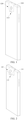
- FIG. 1 is a schematic view illustrating an overall structure of a terminal device in which a rotary camera assembly is in a full-reset state according to some embodiments of the present disclosure
- FIG. 2 is a schematic structural view of the terminal device shown in FIG. 1 in which the rotary camera assembly is in a semi-ejecting state according to some embodiments of the present disclosure
- FIG. 3 is a schematic structural view of the terminal device shown in FIG. 1 in which the rotary camera assembly is in a full-ejecting state.
- the terminal device in some embodiments of the present disclosure may include an electronic device equipped with a camera assembly, such as a mobile phone, a tablet computer, a laptop computer, a wearable device, and the like.
- the terminal device may include a housing 110, a camera module 120, a driving mechanism 130, an operating mechanism or a control mechanism 140, and a display screen 200 (detailed structural features of the driving mechanism 130, the operating mechanism 140, and the display screen 200 may refer to FIGS. 4-5 , and subsequent related description), and the like.
- the terminal device should also include components that are arranged inside the housing 110, such as a circuit board, a battery, a sensor, and the like.
- the circuit board may be configured to control actions of the terminal device, such as display, photographing, and the like.
- the battery may be configured to supply power to the terminal device.
- the camera module 120 in some embodiments of the present disclosure should also be connected to the circuit board, such that the circuit board may control the photographing performed by the camera module 120 and further acquire the captured image information.
- the display screen and the like should also be connected to the circuit board.
- a process, method, system, product, or device that may include a series of steps or units is not limited to the listed steps or units, but optionally also may include steps or units not listed, or optionally may include other steps or units inherent to these processes, methods, products, or equipment.
- FIGS. 1-3 respectively show a full-reset state, a semi-ejecting state, and a full-ejecting state of the camera module 120 of the terminal device.
- the numeral 113 may refer to a sound hole
- the numeral 111 may refer to a receiving groove. The detailed introduction of the sound hole 113 and the receiving groove 111 will be described in detail later in conjunction with the structures of the camera module 120, the driving mechanism 130, and the operating mechanism 140.
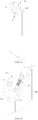
- FIG. 4 is a partial view of the terminal device shown in FIG. 1 according to some embodiments of the present disclosure
- FIG. 5 is a partial side view of the terminal device as shown in FIG. 4 .
- the camera assembly for the terminal device may include a fixing bracket 110, the camera module 120, the driving mechanism 130, and the operating mechanism 140.
- the camera module 120 may be rotatably connected to the fixing bracket 110.
- the driving mechanism 130 may be disposed between the camera module 120 and the fixing bracket 110, and configured to generate a driving force for the rotation of the camera module 120 relative to the fixing bracket 110, drive the camera module 120 to rotate about an axis (using a side edge of the camera module 120 as the axis), such that an opposite side edge of the camera module 120 may rotate away from the fixing bracket 110. In this way, the camera module 120 may face toward a front side of the display screen 200 of the terminal device and further perform the photographing.
- the operating mechanism 140 may be fixed on the fixing bracket 110 and configured to define or limit a position of the camera module 120 when the camera module 120 is in the reset state.
- the fixing bracket 110 is the housing of the terminal device. More specifically, the housing may include a rear shell and a side frame of the terminal device. The housing may define a receiving groove 111 (as further shown in FIG. 3 ). The receiving groove 111 may be configured to receive the camera module 120 in the reset state. In some embodiments, the camera module 120 may be completely or fully received in the receiving groove 111 when the camera module 120 is in the reset state, and will not protrude out of an outer surface of the housing of the terminal device. In this way, the outer surface of the housing of the terminal device may be even, and an overall structure of the terminal device may be more aesthetic. As further shown in FIG. 1 and FIG. 5 , in some embodiments, FIG. 1 is a schematic view illustrating that the camera module 120 is in the full-reset state.
- the camera module 120 may include a body 121 and a camera unit 122 disposed or embedded in the body 121.
- the specific structural features of the camera unit 122 are within the understanding scope of those skilled in the art and will not be described in detail here.
- the camera module in some embodiments of the present disclosure may be a single camera, or may include dual cameras, a plurality of cameras, or may include a camera, a flash, a sensor, and the like, which are packed together.
- the body 121 may be hinged to the fixing bracket 110 through a rotating shaft 102 (a long axis in the broken line shown in FIG. 4 ).
- the driving mechanism 130 may be implemented as a torsion spring.
- the torsion spring may be sleeved on the rotating shaft 102 through which the body 121 is hinged to the fixing bracket 110. Both ends of the torsion force generated by the torsion spring may abut against the body 121 and the fixing bracket 110, respectively.
- the torsion spring may be configured to generate a continuous driving force to drive the camera module 120 to rotate relative to the fixing bracket 110.
- the housing (the fixing bracket 110) of the terminal device may define an engaging groove or slot 112 on a side wall near or adjacent to or close to the receiving groove 111.
- An engaging protrusion 123 may be further disposed at an outer side of the body 121 of the camera module 120 and capable of being engaged with the engaging groove 112. When the camera module 120 is in the reset state, the engaging protrusion 123 may be engaged with the engaging groove 112 in order to realize the positioning of the camera module 120.
- the broken line in FIG. 5 shows a structure of the receiving groove 111 inside the housing (the fixing bracket 110) of the terminal device, and the overall structure in FIG. 5 illustrates a schematic view of the camera assembly in the semi-ejecting state.
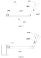
- FIG. 6 is a schematic structural view of an operating mechanism according to some embodiments shown in FIG. 5 .
- the operating mechanism 140 may include an operating key 141 and an operating link 142.
- One end of the operating key 141 may protrude out of the outer surface of the housing (the fixing bracket 110) of the terminal device, and the other end of the operating key 141 may be connected to the operating link 142.
- An end portion of the operating link 142 may be capable of abutting against the engaging protrusion 123 when the engaging protrusion 123 is engaged in the engaging groove 112, such that the engaging protrusion 123 may be capable of disengaged from the engaging groove 112, and the camera module 120 is driven to rotate and be ejected by the driving force of the driving mechanism 130.
- the operating key 141 may abut against the housing (the fixing bracket 110) of the terminal device through a spring 143, in order to generate an elastic reset force applied to the operating key 141.
- an arc-shaped protrusion 144 may be further disposed on a side surface of the operating link 142 that cooperates with the engaging protrusion 123, and the operating link 142 may be capable of abutting against the engaging protrusion 123 through the arc-shaped protrusion 144.
- a movement direction of the operating link 142 may be substantially perpendicular to a direction of a force applied by the operating link 142 to abut against the engaging protrusion 123. That is, an X direction in the FIG. 6 is the moving direction of the operating link 142, and a Y direction is the direction of the force applied by the operating link 142 to abut against the engaging protrusion 123.
- the operating mechanism in this case may have a simple structure.
- the abutting force may be required at a rear side of the arc-shaped protrusion 144.
- the abutting force may help the arc-shaped protrusion 144 to provide an acting force to the engaging protrusion 123, or the operating link 142 needs to move within a sliding groove (not shown).
- FIG. 7 is a schematic structural view of an operating mechanism according to some embodiments of the present disclosure.
- the operating mechanism may include the operating key 141 and the operating link 145. More specifically, the operating link 145 may include a first connecting rod 1451 and a second connecting rod 1452. One end of the first connecting rod 1451 may be connected to the operating key 141, the other end of the first connecting rod 1451 may be hinged to one end of the second connecting rod 1452, and a middle portion or a center of the second connecting rod 1452 may be hinged to the housing (the fixing bracket 110) of the terminal device.
- FIG. 8 is a dynamic view illustrating a position changing of the operating mechanism shown in FIG. 7 . As shown in FIG. 8 , the solid line and the broken line indicate the two positions or states of the operating mechanism.
- the arc-shaped protrusion 144 may be further disposed on a side surface of the second connecting rod 1452 that cooperates or engaging with the engaging protrusion 123, and the operating key 141 may abut against the housing (the fixing bracket 110) of the terminal device through the spring 143 to generate an elastic reset force for the resetting of the operating key 141.
- the operating mechanism shown in FIG. 7 may have a more complex structure.
- the abutting force applied by the arc-shaped protrusion 144 on the second connecting rod 1452 to the engaging protrusion 123 may be generated via the hinge point 1401.
- the housing (the fixing bracket 110) of the terminal device may have less requirements to the constraint conditions to the operating link 145, and the corresponding structures may also be simpler. Details of this structure may be understood by those skilled in the art, and will not be descried in details any more.
- FIG. 9 is a view illustrating a front side of the terminal device shown in FIG. 3 .
- the display screen 200 may be a full screen, that is, all of the front side of the terminal device belongs to a display region 210 of the display screen (or, a screen ratio of the display region of the display screen is greater than a certain ratio, for example, the screen ratio may exceed 80%, and the like).
- the camera module 120 of the camera assembly when the camera module 120 of the camera assembly is in the reset state, the camera module 120 is completely stacked with the display region 210 of the display screen 200, that is, the camera module 120 may be completely disposed below the display region 210 of the display screen 200 when the camera module 120 is in the reset state (as shown in FIG. 1 ).
- FIG. 10 is a view illustrating a front side of the terminal device according to some embodiments of the present disclosure.
- the display screen 200 may have a smaller screen ratio.
- the camera module 120 of the camera assembly may be partially (that is, a part of the structure) stacked with the display region 210 of the display screen 200. That is to say, when the camera module 120 is in the reset state, a part of the camera module 120 may be disposed below the display region 210 of the display screen 200.
- the camera assembly utilizes the driving mechanism to drive the camera module to rotate, such that the camera module may face towards a front side of the display screen and perform the photographing when needed, that is, the rear camera may realize the function of the front camera.
- the camera module may be hidden inside the housing of the terminal device.
- the camera assembly in some embodiments of the present disclosure may have a simple structure, may be convenient to operate, and may not occupy the front space of the terminal device, which may provide a possibility for a full-screen terminal device.
- FIG. 11 is a view illustrating a rear side of the terminal device shown in FIG. 1
- the terminal device may further include a speaker unit 300.
- the frame in the broken line in FIG. 11 may indicate that the speaker unit 300 is disposed inside the rear shell of the terminal device (the fixing bracket 110 in the above embodiment).
- the rear shell may further define the receiving groove 111 configured to receive the camera module 120.
- the speaker unit 300 may further define the sound hole 113 at a position adjacent to the receiving groove 111.
- the sound hole 113 and the receiving groove 111 may communicate with each other inside the rear shell.
- the camera module 120 may be rotatable relative to the rear shell (the fixing bracket 110).
- the camera module 120 rotates to a state in which the camera module 120 at least partially moves or rotates out of the receiving groove 111 (in FIG. 2 , the camera module 120 is rotated to partially eject or move out of the receiving groove 111; in FIG. 3 , the camera module 120 is completely rotated, ejected, or moved out of the receiving groove 111, or may the camera module 120 is rotated to be in a working position state or a maximum position state).
- the receiving groove 111 and the sound hole 113 may together serve as the sound channel of the speaker unit 300.
- All the directional indicator (such as up, down, left, right, front, rear%) in embodiments of the present disclosure are only used for explaining relative positions, the movements, and the like between components in a specific posture (as shown in the drawings) . If the specific posture changes, the directional indicators may change accordingly.
- the sound hole 113 may include a plurality of sub-sound holes 1131 arranged in an array.
- the plurality of sub-sound holes 1131 arranged in an array may be all adjacent to the same side of the receiving groove 111 (in some embodiments as shown in FIG. 11 , this side may be a bottom side; however, in other embodiments, the side may also be a left side, a right side, and the like), and may be located between the receiving groove 111 and the speaker unit 300.
- the receiving groove 111 may be rectangular. However, in some other embodiments, the receiving groove may be irregular shapes or in other shapes. The purpose of this embodiment is to design the plurality of sub-sound holes 1131 of the sound hole 113 in an array or gather together.
- the speaker unit 300 may be at least partially stacked with the display screen 200 of the terminal device, or stacked with the display region 210 of the display screen 200.
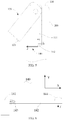
- FIG. 12 is a cross-sectional view of FIG. 11 taken along the line A-A
- FIG. 13 is a schematic view of a terminal device in which a camera module is partially ejected.
- the sound hole 113 may communicate with the receiving groove 111 via a sound channel 103.
- a dust screen (not shown) may be disposed at a port 104 at which the sound channel 103 communicates with the receiving groove 111.
- the dust screen may be configured to reduce the possibility that dusts and other debris enter the sound channel 103 from the port 104 and affects the performance of the speaker unit 300.
- FIG. 14 is a schematic view of a sound channel according to according to some embodiments of the present disclosure.
- a section of the sound channel 1031 between the sound hole 113 and the receiving groove 111 may extend toward a sound output side (along the X direction in FIG. 14 ).
- the sound channel of this inclined structure can make the sound output smoother and facilitate the sound to output from the receiving groove 111.
- another dust screen (not shown) may be further provided at the port at which the sound channel 1031 communicates with the receiving groove 111.
- the sound hole 113 and the receiving groove 111 may both communicate with an inner cavity of the rear shell (the fixing bracket 110 in the foregoing embodiments) of the terminal device. At least a part of the inner cavity of the rear shell of the terminal device may serve as the sound channel of the sound hole 113 and the receiving groove 111, that is, it is possible not to separately design the sound channel, but the inner cavity formed by the rear shell of the terminal device may be utilized as the sound channel, which can make the internal structure of the terminal device (the sound channel) simpler.
- FIG. 15 is a partial view illustrating a rear side of the terminal device according to some embodiments of the present disclosure.
- the sound hole 113 may include a plurality of sub-sound holes 1131.
- the plurality of sub-sound holes 1131 may be uniformly disposed around sides of the receiving groove 111. At least parts of the plurality of sub-sound holes 1131 may be located between the receiving groove 111 and the speaker unit 300.
- the plurality of sub-sound holes 1131 of the sound hole 113 may be uniformly or evenly arranged around three sides of the receiving groove 111.
- the speaker unit 300 may be disposed adjacent to the receiving groove 111. Parts of the sub-sound holes 113 may be disposed between the receiving groove 111 and the speaker unit 300.
- the structure of the sound channel may be similar to that in the previous embodiments, that is, a sound channel structure may be separately arranged.
- the sound channel may be connected to the speaker unit 300 and further connected or communicate the plurality of sub-sound holes 1131 of the sound hole 113 in series.
- a section of the sound channel between the plurality of sub-sound holes 1131 of the sound hole 113 may extend toward a sound output side (along the X direction), to facilitate the sound from being transmitting out of the receiving groove 111.
- the sound hole 113 and the receiving groove 111 may both communicate with the inner cavity of the rear shell of the terminal device (the fixing bracket 110 in the foregoing embodiments).
- At least a part of the inner cavity of the rear shell of the terminal device may serve as the sound channel of the sound hole 113 and the receiving groove 111, that is, it is possible not to separately design the sound channel, but the inner cavity formed by the rear shell of the terminal device may be utilized as the sound channel, which can make the internal structure of the terminal device (the sound channel) simpler.
- the detailed features of this part can refer to the specific description in the above embodiments, and will not be detailed here.
- the receiving groove may be reused as the sound hole of the speaker unit.
- the output volume of the speaker unit may be increased, and the sound output effect of the speaker unit may be improved.
- FIG. 16 is a schematic view of a camera assembly according to some embodiments of the present disclosure.
- the camera assembly may also include a fixing bracket 110, a camera module 120, a driving mechanism 130 and an operating mechanism 140.
- the fixing bracket 110 in some embodiments of the present disclosure is not the housing of the terminal device. Instead, the fixing bracket 110 is a separate structural component. In this way, the camera assembly may individually form an assembly.
- the fixing bracket 110 may be fixedly connected to the housing, a middle frame, or other components of the terminal device. The specific fixed connection between the fixing bracket and the housing or the middle frame of the terminal device and the detailed structural features of the structure of each part of the camera assembly may refer to relevant descriptions in the above embodiments, and will not be repeated here.
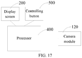
- FIG. 17 is block diagram illustrating a partial configuration of the terminal device according to some embodiments of the present disclosure.
- the terminal device may further include a processor 400.
- the processor 400 may be electrically connected to the camera module 120.
- the processor 400 may be configured to control the camera module 120 to perform the photographing. More specifically, the processor 400 may be configured to receive a control instruction, and then control the camera module 120 to turn on, photograph, turn off, and the like.
- the control instruction received by the processor 400 may be a touch operation received by the display screen 200 (herein, it should be noted that, in some embodiments, the display screen 200 may be a touch display screen).
- the touch operation may include, but be not limited to, at least one of sliding, clicking, long-pressing, and the like.
- the specific form of the touch operation may be set according to different types of the terminal devices, user habits, and the like, and will not specifically limited herein.
- the terminal device may further include a controlling button 500.
- the control instruction may include a trigger instruction configured to trigger the controlling button.
- the controlling button 500 may be a single button, or may be reused with other function buttons (such as a power button, a volume button, and the like) of the terminal device. It may be defined that the process 400 receives different control instructions according to different triggering methods of the buttons.
- the control instruction may include at least one of the following: an image acquisition requirement, a flash activation requirement, and a speaker activation requirement. More specifically, the image acquisition requirement may be applied to scenarios where the user has a shooting requirement (such as photographing, camera shooting, video calling, and the like), a unlocking requirement for the terminal device, a requirement for mobile payment, a requirement for file encryption, a requirement for answering an incoming call, or other confirmation requirements.
- the flash activation requirement may be a requirement that when the camera module 120 includes a flash, if the user needs to turn on the flash, the processor 400 may control to turn the flash on or off. Similarly, in the case where the camera module 120 includes a speaker (or an earpiece), when the user needs to use the speaker, the corresponding control instruction may be triggered.
- the image acquisition requirement may specifically include the shooting requirement (photographing, video recording, video calling, and the like), a unlocking requirement for the terminal device, a requirement for mobile payment, a requirement for file encryption, a requirement for answering an incoming call, or other confirmation requirements), it is possible to touch a corresponding touch function area icon on the touch screen, the processor 400 may receive the corresponding control instruction, and then control the camera module 120 to turn on, shoot, turn off, or the like. Thus, the camera may finish an image acquisition action.
Landscapes
- Engineering & Computer Science (AREA)
- Signal Processing (AREA)
- Multimedia (AREA)
- Physics & Mathematics (AREA)
- Computer Hardware Design (AREA)
- Theoretical Computer Science (AREA)
- Acoustics & Sound (AREA)
- Human Computer Interaction (AREA)
- General Engineering & Computer Science (AREA)
- General Physics & Mathematics (AREA)
- Studio Devices (AREA)
Abstract
Description
- The described embodiments relates to the field of terminal devices, and in particular, to a terminal device and a camera assembly thereof.
- At present, camera functions are indispensable to terminal devices such as mobile phones. Front cameras are also required by many people, since the front cameras can meet the needs of selfies and video calls. However, with the popularization of full screens of the mobile phones, there is no room for arranging the front cameras at sides at which the screens are located any longer.
- In some aspects of the present disclosure, a rotatory camera assembly for a terminal device may be provided. The camera assembly may include: a fixing bracket, a camera module, a driving mechanism, and an operating mechanism. The camera module is rotatably connected to the fixing bracket. The driving mechanism is disposed between the camera module and the fixing bracket and configured to generate a driving force to drive the camera module to rotate relative to the fixing bracket to drive the camera module to rotate about a side edge of the camera module, such that an opposite side edge of the camera module is capable of rotating away from the fixing bracket. The operating mechanism is fixed on the fixing bracket and configured to limit a position of the camera module when the camera module is in a reset state.
- In some aspects of the present disclosure, a terminal device may be further provided. The terminal device may include: a display screen, a processor; and a camera assembly. The camera assembly may include: a fixing bracket, a camera module, a driving mechanism, and an operating mechanism. The camera module is rotatably connected to the fixing bracket. The driving mechanism is disposed between the camera module and the fixing bracket and configured to generate a driving force to drive the camera module to rotate relative to the fixing bracket and further drive the camera module to rotate about a side edge of the camera module, such that an opposite side edge of the camera module is capable of rotating away from the fixing bracket. The operating mechanism is fixed on the fixing bracket and configured to limit a position of the camera module when the camera module is in a reset state. The processor is configured to receive a control instruction of the display screen and control the camera module in the camera assembly to shoot according to the control instruction.
- Furthermore, in some aspects of the present disclosure, a terminal device may be further provided. The terminal device may include: a housing, a camera module, a driving mechanism, and an operating mechanism. The camera module is rotatably connected to the housing. The driving mechanism is disposed between the camera module and the housing and configured to generate a driving force to drive the camera module to rotate relative to the housing and further drive the camera module to rotate about a side edge of the camera module, such that an opposite side edge of the camera module is capable of rotating away from the housing. The operating mechanism is fixed on the housing and configured to limit a position of the camera module when the camera module is in a reset state.
- In order to describe the technical solutions in the embodiments of the present disclosure more clearly, the drawings required to be used in descriptions of the embodiments will be briefly described below. Obviously, the drawings described below are only some embodiments of the present disclosure, and those skilled in the art may obtain other drawings according to the drawings without creative efforts.
-
FIG. 1 is a schematic view illustrating an overall structure of a terminal device in which a rotary camera assembly is in a full-reset state according to some embodiments of the present disclosure. -
FIG. 2 is a schematic structural view of the terminal device shown inFIG. 1 in which the rotary camera assembly is in a semi-ejecting state according to some embodiments of the present disclosure. -
FIG. 3 is a schematic structural view of the terminal device shown inFIG. 1 in which the rotary camera assembly is in a full-ejecting state. -
FIG. 4 is a partial view of the terminal device shown inFIG. 1 according to some embodiments of the present disclosure. -
FIG. 5 is a partial side view of the terminal device as shown inFIG. 4 . -
FIG. 6 is a schematic structural view of an operating mechanism according to some embodiments shown inFIG. 5 . -
FIG. 7 is a schematic structural view of an operating mechanism according to some embodiments of the present disclosure. -
FIG. 8 is a dynamic view illustrating a position changing of the operating mechanism shown inFIG. 7 . -
FIG. 9 is a view illustrating a front side of the terminal device shown inFIG. 3 . -
FIG. 10 is a view illustrating a front side of the terminal device according to some embodiments of the present disclosure. -
FIG. 11 is a view illustrating a rear side of the terminal device shown inFIG. 1 . -
FIG. 12 is a cross-sectional view ofFIG. 11 taken along the line A-A. -
FIG. 13 is a schematic view of a terminal device in which a camera module is partially ejected. -
FIG. 14 is a schematic view of a sound channel according to according to some embodiments of the present disclosure. -
FIG. 15 is a partial view illustrating a rear side of the terminal device according to some embodiments of the present disclosure. -
FIG. 16 is a schematic view of a camera assembly according to some embodiments of the present disclosure. -
FIG. 17 is block diagram illustrating a partial configuration of the terminal device according to some embodiments of the present disclosure. - The technical solutions in some embodiments of the present disclosure will be described clearly and completely in conjunction with the drawings in some embodiments of the present disclosure. Apparently, the described embodiments are only a part of the embodiments of the present disclosure, not all the embodiments. Based on the embodiments of the present disclosure, those skilled in the art may acquire other embodiments without making creative efforts. All these embodiments fall within the protection scope of the present disclosure.
- "Embodiment" herein means that a particular feature, structure, or characteristic described with reference to embodiments may be included in at least one embodiment of the present disclosure. The term appearing in various places in the specification are not necessarily as shown in the same embodiment, and are not exclusive or alternative embodiments that are mutually exclusive with other embodiments. Those skilled in the art will understand explicitly and implicitly that the embodiments described herein may be combined with other embodiments.
- In some aspects of the present disclosure, a rotatory camera assembly for a terminal device may be provided. The camera assembly may include: a fixing bracket, a camera module, a driving mechanism, and an operating mechanism. The camera module is rotatably connected to the fixing bracket. The driving mechanism is disposed between the camera module and the fixing bracket and configured to generate a driving force to drive the camera module to rotate relative to the fixing bracket to drive the camera module to rotate about a side edge of the camera module, such that an opposite side edge of the camera module is capable of rotating away from the fixing bracket. The operating mechanism is fixed on the fixing bracket and configured to limit a position of the camera module when the camera module is in a reset state.
- In some embodiments, the camera module may include a body and a camera unit disposed inside the body, and the body is hinged to the fixing bracket through a rotating shaft.
- In some embodiments, the driving mechanism is a torsion spring, and the torsion spring is sleeved on the rotating shaft through which the body and the fixing bracket are hinged to, and both ends of a torsion force generated by the torsion spring abut against the body and the fixing bracket, respectively, and the torsion spring is configured to generate a continuous driving force to drive the camera module to rotate relative to the fixing bracket.
- In some embodiments, the fixing bracket defines a receiving groove configured to receive the camera module in the reset state.
- When the camera module is in the reset state, the camera module is completely received in the receiving groove without protruding out of an outer surface of the fixing bracket.
- In some embodiments, the fixing bracket defines an engaging groove on a side wall adjacent to the receiving groove, and an engaging protrusion is disposed at an outer side of the body and capable of being engaged with the engaging groove; when the camera module in the reset state, the engaging protrusion is engaged with the engaging groove to position the camera module.
- In some embodiments, the operating mechanism may include: an operating key, wherein one end of the operating key protrudes out of the outer surface of the fixing bracket, and the other end of the operating key is connected to the operating link; and an operating link, wherein the operating link has an end portion capable of abutting against the engaging protrusion when the engaging protrusion is engaged in the engaging groove, such that the engaging protrusion is capable of being disengaged from the engaging groove and the camera module is driven to rotate and being ejected by the driving force of the driving mechanism.
- In some embodiments, an arc-shaped protrusion is further disposed on a side surface of the operating link that cooperates with the engaging protrusion, and the operating link is capable of abutting against the engaging protrusion through the arc-shaped protrusion; a movement direction of the operating link is perpendicular to a direction of a force applied by the operating link to abut against the engaging protrusion.
- In some embodiments, the operating link may include a first connecting rod and a second connecting rod. One end of the first connecting rod is connected to the operating key, the other end of the first connecting rod is hinged to one end of the second connecting rod, and a middle portion of the second connecting rod is hinged to the fixing bracket. The second connecting rod is rotatable about a hinge point to which the fixing bracket is hinged, and the other end of the second connecting rod is capable of rotating into the engaging groove and further abutting against the engaging protrusion located in the engaging groove.
- In some aspects of the present disclosure, a terminal device may be further provided. The terminal device may include: a display screen, a processor; and a camera assembly. The camera assembly may include: a fixing bracket, a camera module, a driving mechanism, and an operating mechanism. The camera module is rotatably connected to the fixing bracket. The driving mechanism is disposed between the camera module and the fixing bracket and configured to generate a driving force to drive the camera module to rotate relative to the fixing bracket and further drive the camera module to rotate about a side edge of the camera module, such that an opposite side edge of the camera module is capable of rotating away from the fixing bracket. The operating mechanism is fixed on the fixing bracket and configured to limit a position of the camera module when the camera module is in a reset state. The processor is configured to receive a control instruction of the display screen and control the camera module in the camera assembly to shoot according to the control instruction.
- In some embodiments, the control instruction of the display screen may include at least one of sliding, clicking, and long-pressing.
- In some embodiments, the terminal device may include a controlling button, and the control instruction further may include a trigger instruction of the controlling button.
- In some embodiments, the control instruction may include at least one of an image acquisition requirement, a flash activation requirement, and a speaker activation requirement.
- In some aspects of the present disclosure, a terminal device may be further provided. The terminal device may include: a housing, a camera module, a driving mechanism, and an operating mechanism. The camera module is rotatably connected to the housing. The driving mechanism is disposed between the camera module and the housing and configured to generate a driving force to drive the camera module to rotate relative to the housing and further drive the camera module to rotate about a side edge of the camera module, such that an opposite side edge of the camera module is capable of rotating away from the housing. The operating mechanism is fixed on the housing and configured to limit a position of the camera module when the camera module is in a reset state.
- In some embodiments, the housing defines a receiving groove configured to receive the camera module when the camera module in the reset state.
- The camera module may include a body and a camera unit disposed inside the body, and the body is hinged to the housing through a rotating shaft; the housing defines an engaging groove on a side wall adjacent to the receiving groove, and an engaging protrusion is disposed at an outer side of the body and capable of being engaged with the engaging groove; when the camera module in the reset state, the engaging protrusion is engaged with the engaging groove to position the camera module.
- In some embodiments, the driving mechanism is a torsion spring, and the torsion spring is sleeved on the rotating shaft through which the body and the housing are hinged to, and both ends of a torsion force generated by the torsion spring abut against the body and the housing, respectively, and the torsion spring is configured to generate a continuous driving force to drive the camera module to rotate relative to the housing.
- When the camera module is in the reset state, the camera module is completely received in the receiving groove without protruding out of an outer surface of the fixing bracket.
- In some embodiments, the housing defines an engaging groove on a side wall adjacent to the receiving groove, and an engaging protrusion is disposed at an outer side of the body and capable of being engaged with the engaging groove; when the camera module in the reset state, the engaging protrusion is engaged with the engaging groove to position the camera module.
- In some embodiments, the operating mechanism may include: an operating key, wherein one end of the operating key protrudes out of an outer surface of the housing, and the other end of the operating key is connected to the operating link; and an operating link, wherein the operating link has an end portion capable of abutting against the engaging protrusion when the engaging protrusion is engaged in the engaging groove, such that the engaging protrusion is capable of being disengaged from the engaging groove and the camera module is driven to rotate and being ejected by the driving force of the driving mechanism.
- In some embodiments, an arc-shaped protrusion is further disposed on a side surface of the operating link that cooperates with the engaging protrusion, and the operating link is capable of abutting against the engaging protrusion through the arc-shaped protrusion; a movement direction of the operating link is perpendicular to a direction of a force applied by the operating link to abut against the engaging protrusion.
- In some embodiments, the operating link may include a first connecting rod and a second connecting rod. One end of the first connecting rod is connected to the operating key, the other end of the first connecting rod is hinged to one end of the second connecting rod, and a middle portion of the second connecting rod is hinged to the housing ; the second connecting rod is rotatable about a hinge point to which the housing is hinged, and the other end of the second connecting rod rotates into the engaging groove and further abuts against the engaging protrusion located in the engaging groove.
- In some embodiments, the terminal device further comprises a display screen, and at least a part of the camera module is stacked on the display screen when the camera module is in the reset state.
- As shown in
FIG. 1 to FIG. 3 ,FIG. 1 is a schematic view illustrating an overall structure of a terminal device in which a rotary camera assembly is in a full-reset state according to some embodiments of the present disclosure,FIG. 2 is a schematic structural view of the terminal device shown inFIG. 1 in which the rotary camera assembly is in a semi-ejecting state according to some embodiments of the present disclosure, andFIG. 3 is a schematic structural view of the terminal device shown inFIG. 1 in which the rotary camera assembly is in a full-ejecting state. It should be noted that the terminal device in some embodiments of the present disclosure may include an electronic device equipped with a camera assembly, such as a mobile phone, a tablet computer, a laptop computer, a wearable device, and the like. - The terminal device may include a
housing 110, acamera module 120, adriving mechanism 130, an operating mechanism or acontrol mechanism 140, and a display screen 200 (detailed structural features of thedriving mechanism 130, theoperating mechanism 140, and thedisplay screen 200 may refer toFIGS. 4-5 , and subsequent related description), and the like. Of course, the terminal device should also include components that are arranged inside thehousing 110, such as a circuit board, a battery, a sensor, and the like. The circuit board may be configured to control actions of the terminal device, such as display, photographing, and the like. The battery may be configured to supply power to the terminal device. Thecamera module 120 in some embodiments of the present disclosure should also be connected to the circuit board, such that the circuit board may control the photographing performed by thecamera module 120 and further acquire the captured image information. Of course, the display screen and the like should also be connected to the circuit board. As to the detailed structural connection and data parameters of this part, on one hand, since these features are located in thehousing 110 and invisible in the figures, on the other hand, these technical features (circuit board, battery, sensor, and the like) do not relate to the innovation of the technical solution of the present disclosure, thus these features will not be described in detail here. Furthermore, the terms "including" and "having", and any modification thereof are intended to cover un-exclusive inclusion. For example, a process, method, system, product, or device that may include a series of steps or units is not limited to the listed steps or units, but optionally also may include steps or units not listed, or optionally may include other steps or units inherent to these processes, methods, products, or equipment. - In some embodiments of the present disclosure,
FIGS. 1-3 respectively show a full-reset state, a semi-ejecting state, and a full-ejecting state of thecamera module 120 of the terminal device. In some embodiments as shown inFIGS. 1-3 , the numeral 113 may refer to a sound hole, the numeral 111 may refer to a receiving groove. The detailed introduction of thesound hole 113 and the receivinggroove 111 will be described in detail later in conjunction with the structures of thecamera module 120, thedriving mechanism 130, and theoperating mechanism 140. - As shown in
FIGS. 4-5 ,FIG. 4 is a partial view of the terminal device shown inFIG. 1 according to some embodiments of the present disclosure, andFIG. 5 is a partial side view of the terminal device as shown inFIG. 4 . The camera assembly for the terminal device may include a fixingbracket 110, thecamera module 120, thedriving mechanism 130, and theoperating mechanism 140. - In some embodiments, the
camera module 120 may be rotatably connected to the fixingbracket 110. Thedriving mechanism 130 may be disposed between thecamera module 120 and the fixingbracket 110, and configured to generate a driving force for the rotation of thecamera module 120 relative to the fixingbracket 110, drive thecamera module 120 to rotate about an axis (using a side edge of thecamera module 120 as the axis), such that an opposite side edge of thecamera module 120 may rotate away from the fixingbracket 110. In this way, thecamera module 120 may face toward a front side of thedisplay screen 200 of the terminal device and further perform the photographing. Theoperating mechanism 140 may be fixed on the fixingbracket 110 and configured to define or limit a position of thecamera module 120 when thecamera module 120 is in the reset state. - More specifically, in some embodiments, the fixing
bracket 110 is the housing of the terminal device. More specifically, the housing may include a rear shell and a side frame of the terminal device. The housing may define a receiving groove 111 (as further shown inFIG. 3 ). The receivinggroove 111 may be configured to receive thecamera module 120 in the reset state. In some embodiments, thecamera module 120 may be completely or fully received in the receivinggroove 111 when thecamera module 120 is in the reset state, and will not protrude out of an outer surface of the housing of the terminal device. In this way, the outer surface of the housing of the terminal device may be even, and an overall structure of the terminal device may be more aesthetic. As further shown inFIG. 1 andFIG. 5 , in some embodiments,FIG. 1 is a schematic view illustrating that thecamera module 120 is in the full-reset state. - The
camera module 120 may include abody 121 and acamera unit 122 disposed or embedded in thebody 121. The specific structural features of thecamera unit 122 are within the understanding scope of those skilled in the art and will not be described in detail here. Further, the camera module in some embodiments of the present disclosure may be a single camera, or may include dual cameras, a plurality of cameras, or may include a camera, a flash, a sensor, and the like, which are packed together. In some embodiments, thebody 121 may be hinged to the fixingbracket 110 through a rotating shaft 102 (a long axis in the broken line shown inFIG. 4 ). - In some embodiments, the
driving mechanism 130 may be implemented as a torsion spring. In some embodiments, the torsion spring may be sleeved on therotating shaft 102 through which thebody 121 is hinged to the fixingbracket 110. Both ends of the torsion force generated by the torsion spring may abut against thebody 121 and the fixingbracket 110, respectively. The torsion spring may be configured to generate a continuous driving force to drive thecamera module 120 to rotate relative to the fixingbracket 110. - As further shown in
FIG. 5 , the housing (the fixing bracket 110) of the terminal device may define an engaging groove or slot 112 on a side wall near or adjacent to or close to the receivinggroove 111. An engagingprotrusion 123 may be further disposed at an outer side of thebody 121 of thecamera module 120 and capable of being engaged with the engaginggroove 112. When thecamera module 120 is in the reset state, the engagingprotrusion 123 may be engaged with the engaginggroove 112 in order to realize the positioning of thecamera module 120. The broken line inFIG. 5 shows a structure of the receivinggroove 111 inside the housing (the fixing bracket 110) of the terminal device, and the overall structure inFIG. 5 illustrates a schematic view of the camera assembly in the semi-ejecting state. - As shown in
FIG. 5 and FIG. 6, FIG. 6 is a schematic structural view of an operating mechanism according to some embodiments shown inFIG. 5 . In some embodiments, theoperating mechanism 140 may include an operatingkey 141 and anoperating link 142. One end of the operating key 141 may protrude out of the outer surface of the housing (the fixing bracket 110) of the terminal device, and the other end of the operating key 141 may be connected to theoperating link 142. An end portion of theoperating link 142 may be capable of abutting against the engagingprotrusion 123 when the engagingprotrusion 123 is engaged in the engaginggroove 112, such that the engagingprotrusion 123 may be capable of disengaged from the engaginggroove 112, and thecamera module 120 is driven to rotate and be ejected by the driving force of thedriving mechanism 130. In some embodiments, the operating key 141 may abut against the housing (the fixing bracket 110) of the terminal device through aspring 143, in order to generate an elastic reset force applied to the operatingkey 141. - Furthermore, as shown in
FIG. 6 , an arc-shapedprotrusion 144 may be further disposed on a side surface of theoperating link 142 that cooperates with the engagingprotrusion 123, and theoperating link 142 may be capable of abutting against the engagingprotrusion 123 through the arc-shapedprotrusion 144. In some embodiments, a movement direction of theoperating link 142 may be substantially perpendicular to a direction of a force applied by theoperating link 142 to abut against the engagingprotrusion 123. That is, an X direction in theFIG. 6 is the moving direction of theoperating link 142, and a Y direction is the direction of the force applied by theoperating link 142 to abut against the engagingprotrusion 123. The operating mechanism in this case may have a simple structure. However, the abutting force may be required at a rear side of the arc-shapedprotrusion 144. The abutting force may help the arc-shapedprotrusion 144 to provide an acting force to the engagingprotrusion 123, or theoperating link 142 needs to move within a sliding groove (not shown). - As shown in
FIG. 7, FIG. 7 is a schematic structural view of an operating mechanism according to some embodiments of the present disclosure. In some embodiments, the operating mechanism may include the operatingkey 141 and theoperating link 145. More specifically, theoperating link 145 may include a first connectingrod 1451 and a second connectingrod 1452. One end of the first connectingrod 1451 may be connected to the operatingkey 141, the other end of the first connectingrod 1451 may be hinged to one end of the second connectingrod 1452, and a middle portion or a center of the second connectingrod 1452 may be hinged to the housing (the fixing bracket 110) of the terminal device. It should be noted that, terms such as "first", "second", "third", and the like, are used herein for purposes of description, and are not intended to indicate or imply relative importance or significance or to imply the number of indicated technical features. Thus, the feature defined with "first", "second", "third", and the like may include one or more of such a feature. In the description of the present disclosure, it should be noted that, "a plurality of' means two or more, unless specified otherwise. - Driven by the first connecting
rod 1451, the second connectingrod 1452 is rotatable about ahinge point 1401 which is hinged to the housing (the fixing bracket 110) of the terminal device, and the other end of the second connectingrod 1452 may be capable of rotating into the engaging groove 112 (as shown inFIG. 5 ), and further abutting against the engagingprotrusion 123 located in the engaginggroove 112, such that the engagingprotrusion 123 may be capable of being disengaged from the engaginggroove 112. Furthermore, thecamera module 120 may be rotated and ejected by the driving force of thedriving mechanism 130.FIG. 8 is a dynamic view illustrating a position changing of the operating mechanism shown inFIG. 7 . As shown inFIG. 8 , the solid line and the broken line indicate the two positions or states of the operating mechanism. - Similarly, the arc-shaped
protrusion 144 may be further disposed on a side surface of the second connectingrod 1452 that cooperates or engaging with the engagingprotrusion 123, and the operating key 141 may abut against the housing (the fixing bracket 110) of the terminal device through thespring 143 to generate an elastic reset force for the resetting of the operatingkey 141. Compared with the operating mechanism shown inFIG. 6 , the operating mechanism shown inFIG. 7 may have a more complex structure. However, as shown inFIG. 7 , the abutting force applied by the arc-shapedprotrusion 144 on the second connectingrod 1452 to the engagingprotrusion 123 may be generated via thehinge point 1401. Thus, the housing (the fixing bracket 110) of the terminal device may have less requirements to the constraint conditions to theoperating link 145, and the corresponding structures may also be simpler. Details of this structure may be understood by those skilled in the art, and will not be descried in details any more. - In some embodiments, when the
camera module 120 is in the reset state, thecamera module 120 of the camera assembly may be at least partially stacked with thedisplay screen 200. As shown inFIG. 9, FIG. 9 is a view illustrating a front side of the terminal device shown inFIG. 3 . As shown inFIG. 9 , thedisplay screen 200 may be a full screen, that is, all of the front side of the terminal device belongs to adisplay region 210 of the display screen (or, a screen ratio of the display region of the display screen is greater than a certain ratio, for example, the screen ratio may exceed 80%, and the like). Therefore, in some embodiments, when thecamera module 120 of the camera assembly is in the reset state, thecamera module 120 is completely stacked with thedisplay region 210 of thedisplay screen 200, that is, thecamera module 120 may be completely disposed below thedisplay region 210 of thedisplay screen 200 when thecamera module 120 is in the reset state (as shown inFIG. 1 ). - Furthermore, as shown in
FIG. 10, FIG. 10 is a view illustrating a front side of the terminal device according to some embodiments of the present disclosure. Compared with the terminal device described in the previous embodiment, in some embodiments as shown inFIG. 10 , thedisplay screen 200 may have a smaller screen ratio. In this case, when thecamera module 120 is in the reset state, thecamera module 120 of the camera assembly may be partially (that is, a part of the structure) stacked with thedisplay region 210 of thedisplay screen 200. That is to say, when thecamera module 120 is in the reset state, a part of thecamera module 120 may be disposed below thedisplay region 210 of thedisplay screen 200. - In the terminal device with a rotary camera assembly according to some embodiments of the present disclosure, the camera assembly utilizes the driving mechanism to drive the camera module to rotate, such that the camera module may face towards a front side of the display screen and perform the photographing when needed, that is, the rear camera may realize the function of the front camera. When the camera is not needed, the camera module may be hidden inside the housing of the terminal device. The camera assembly in some embodiments of the present disclosure may have a simple structure, may be convenient to operate, and may not occupy the front space of the terminal device, which may provide a possibility for a full-screen terminal device.
- As further shown in
FIG. 1, FIG. 2 ,FIG. 3 andFIG. 11, FIG. 11 is a view illustrating a rear side of the terminal device shown inFIG. 1 , the terminal device may further include aspeaker unit 300. The frame in the broken line inFIG. 11 may indicate that thespeaker unit 300 is disposed inside the rear shell of the terminal device (the fixingbracket 110 in the above embodiment). The rear shell may further define the receivinggroove 111 configured to receive thecamera module 120. Thespeaker unit 300 may further define thesound hole 113 at a position adjacent to the receivinggroove 111. Thesound hole 113 and the receivinggroove 111 may communicate with each other inside the rear shell. - The
camera module 120 may be rotatable relative to the rear shell (the fixing bracket 110). When thecamera module 120 rotates to a state in which thecamera module 120 at least partially moves or rotates out of the receiving groove 111 (inFIG. 2 , thecamera module 120 is rotated to partially eject or move out of the receivinggroove 111; inFIG. 3 , thecamera module 120 is completely rotated, ejected, or moved out of the receivinggroove 111, or may thecamera module 120 is rotated to be in a working position state or a maximum position state). The receivinggroove 111 and thesound hole 113 may together serve as the sound channel of thespeaker unit 300. All the directional indicator (such as up, down, left, right, front, rear...) in embodiments of the present disclosure are only used for explaining relative positions, the movements, and the like between components in a specific posture (as shown in the drawings) . If the specific posture changes, the directional indicators may change accordingly. - In some embodiments, the
sound hole 113 may include a plurality ofsub-sound holes 1131 arranged in an array. The plurality ofsub-sound holes 1131 arranged in an array may be all adjacent to the same side of the receiving groove 111 (in some embodiments as shown inFIG. 11 , this side may be a bottom side; however, in other embodiments, the side may also be a left side, a right side, and the like), and may be located between the receivinggroove 111 and thespeaker unit 300. In the drawings, the receivinggroove 111 may be rectangular. However, in some other embodiments, the receiving groove may be irregular shapes or in other shapes. The purpose of this embodiment is to design the plurality ofsub-sound holes 1131 of thesound hole 113 in an array or gather together. - Similarly, as further shown in
FIGS. 9-11 , in some embodiments, thespeaker unit 300 may be at least partially stacked with thedisplay screen 200 of the terminal device, or stacked with thedisplay region 210 of thedisplay screen 200. - As shown in
FIG. 12 andFIG. 13 ,FIG. 12 is a cross-sectional view ofFIG. 11 taken along the line A-A, andFIG. 13 is a schematic view of a terminal device in which a camera module is partially ejected. Thesound hole 113 may communicate with the receivinggroove 111 via asound channel 103. A dust screen (not shown) may be disposed at aport 104 at which thesound channel 103 communicates with the receivinggroove 111. The dust screen may be configured to reduce the possibility that dusts and other debris enter thesound channel 103 from theport 104 and affects the performance of thespeaker unit 300. - Furthermore, as shown in
FIG. 14, FIG. 14 is a schematic view of a sound channel according to according to some embodiments of the present disclosure. Unlike the sound channel descried in the previous embodiments, in some embodiments, a section of thesound channel 1031 between thesound hole 113 and the receivinggroove 111 may extend toward a sound output side (along the X direction inFIG. 14 ). The sound channel of this inclined structure can make the sound output smoother and facilitate the sound to output from the receivinggroove 111. Similarly, another dust screen (not shown) may be further provided at the port at which thesound channel 1031 communicates with the receivinggroove 111. - In addition, in other embodiments, the
sound hole 113 and the receivinggroove 111 may both communicate with an inner cavity of the rear shell (the fixingbracket 110 in the foregoing embodiments) of the terminal device. At least a part of the inner cavity of the rear shell of the terminal device may serve as the sound channel of thesound hole 113 and the receivinggroove 111, that is, it is possible not to separately design the sound channel, but the inner cavity formed by the rear shell of the terminal device may be utilized as the sound channel, which can make the internal structure of the terminal device (the sound channel) simpler. - As shown in
FIG. 15, FIG. 15 is a partial view illustrating a rear side of the terminal device according to some embodiments of the present disclosure. In some embodiments, as shown inFIG. 15 , thesound hole 113 may include a plurality ofsub-sound holes 1131. The plurality ofsub-sound holes 1131 may be uniformly disposed around sides of the receivinggroove 111. At least parts of the plurality ofsub-sound holes 1131 may be located between the receivinggroove 111 and thespeaker unit 300. In some embodiments, the plurality ofsub-sound holes 1131 of thesound hole 113 may be uniformly or evenly arranged around three sides of the receivinggroove 111. Thespeaker unit 300 may be disposed adjacent to the receivinggroove 111. Parts of thesub-sound holes 113 may be disposed between the receivinggroove 111 and thespeaker unit 300. - In addition, the structure of the sound channel may be similar to that in the previous embodiments, that is, a sound channel structure may be separately arranged. The sound channel may be connected to the
speaker unit 300 and further connected or communicate the plurality ofsub-sound holes 1131 of thesound hole 113 in series. Similarly, a section of the sound channel between the plurality ofsub-sound holes 1131 of thesound hole 113 may extend toward a sound output side (along the X direction), to facilitate the sound from being transmitting out of the receivinggroove 111. Of course, in some embodiments, thesound hole 113 and the receivinggroove 111 may both communicate with the inner cavity of the rear shell of the terminal device (the fixingbracket 110 in the foregoing embodiments). At least a part of the inner cavity of the rear shell of the terminal device may serve as the sound channel of thesound hole 113 and the receivinggroove 111, that is, it is possible not to separately design the sound channel, but the inner cavity formed by the rear shell of the terminal device may be utilized as the sound channel, which can make the internal structure of the terminal device (the sound channel) simpler. The detailed features of this part can refer to the specific description in the above embodiments, and will not be detailed here. - In the terminal device according to some embodiments of the present disclosure, by disposing the speaker unit near or adjacent to the receiving groove of the camera module, when the camera module is rotated out of the receiving groove, the receiving groove may be reused as the sound hole of the speaker unit. When the structure of the terminal device is unchanged, the output volume of the speaker unit may be increased, and the sound output effect of the speaker unit may be improved.
- As shown in
FIG. 16, FIG. 16 is a schematic view of a camera assembly according to some embodiments of the present disclosure. In some embodiments shown inFIG. 16 , the camera assembly may also include a fixingbracket 110, acamera module 120, adriving mechanism 130 and anoperating mechanism 140. Different from the camera assembly described in the previous embodiments, the fixingbracket 110 in some embodiments of the present disclosure is not the housing of the terminal device. Instead, the fixingbracket 110 is a separate structural component. In this way, the camera assembly may individually form an assembly. The fixingbracket 110 may be fixedly connected to the housing, a middle frame, or other components of the terminal device. The specific fixed connection between the fixing bracket and the housing or the middle frame of the terminal device and the detailed structural features of the structure of each part of the camera assembly may refer to relevant descriptions in the above embodiments, and will not be repeated here. - As shown in
FIG. 17, FIG. 17 is block diagram illustrating a partial configuration of the terminal device according to some embodiments of the present disclosure. In some embodiments, the terminal device may further include aprocessor 400. In some embodiments, theprocessor 400 may be electrically connected to thecamera module 120. Theprocessor 400 may be configured to control thecamera module 120 to perform the photographing. More specifically, theprocessor 400 may be configured to receive a control instruction, and then control thecamera module 120 to turn on, photograph, turn off, and the like. The control instruction received by theprocessor 400 may be a touch operation received by the display screen 200 (herein, it should be noted that, in some embodiments, thedisplay screen 200 may be a touch display screen). The touch operation may include, but be not limited to, at least one of sliding, clicking, long-pressing, and the like. The specific form of the touch operation may be set according to different types of the terminal devices, user habits, and the like, and will not specifically limited herein. - As further shown in
FIGS. 1-3 , according to some embodiments of the present embodiment, the terminal device may further include acontrolling button 500. The control instruction may include a trigger instruction configured to trigger the controlling button. Thecontrolling button 500 may be a single button, or may be reused with other function buttons (such as a power button, a volume button, and the like) of the terminal device. It may be defined that theprocess 400 receives different control instructions according to different triggering methods of the buttons. - In some embodiments, the control instruction may include at least one of the following: an image acquisition requirement, a flash activation requirement, and a speaker activation requirement. More specifically, the image acquisition requirement may be applied to scenarios where the user has a shooting requirement (such as photographing, camera shooting, video calling, and the like), a unlocking requirement for the terminal device, a requirement for mobile payment, a requirement for file encryption, a requirement for answering an incoming call, or other confirmation requirements. The flash activation requirement may be a requirement that when the
camera module 120 includes a flash, if the user needs to turn on the flash, theprocessor 400 may control to turn the flash on or off. Similarly, in the case where thecamera module 120 includes a speaker (or an earpiece), when the user needs to use the speaker, the corresponding control instruction may be triggered. - For example, take the image acquisition requirement as an example. When the user needs to acquire an image when operating the terminal device (as mentioned above, the image acquisition requirement may specifically include the shooting requirement (photographing, video recording, video calling, and the like), a unlocking requirement for the terminal device, a requirement for mobile payment, a requirement for file encryption, a requirement for answering an incoming call, or other confirmation requirements), it is possible to touch a corresponding touch function area icon on the touch screen, the
processor 400 may receive the corresponding control instruction, and then control thecamera module 120 to turn on, shoot, turn off, or the like. Thus, the camera may finish an image acquisition action. - The above are only some embodiments of the present disclosure and are not intended to limit the protection scope of the present disclosure. Any equivalent device or equivalent process transformation made according to the description and the drawings of the present disclosure, or directly or indirectly used in other related technical field should be included in the protection scope of the present disclosure.
Claims (20)
- A camera assembly for a terminal device, comprising:a fixing bracket;a camera module, rotatably connected to the fixing bracket;a driving mechanism, disposed between the camera module and the fixing bracket and configured to generate a driving force to drive the camera module to rotate relative to the fixing bracket to drive the camera module to rotate about a side edge of the camera module, such that an opposite side edge of the camera module is capable of rotating away from the fixing bracket; andan operating mechanism, fixed on the fixing bracket and configured to limit a position of the camera module when the camera module is in a reset state.
- The camera assembly as claimed in claim 1, wherein the camera module comprises a body and a camera unit disposed inside the body, and the body is hinged to the fixing bracket through a rotating shaft.
- The camera assembly as claimed in claim 2, wherein the driving mechanism is a torsion spring, and the torsion spring is sleeved on the rotating shaft through which the body and the fixing bracket are hinged to, and both ends of a torsion force generated by the torsion spring abut against the body and the fixing bracket, respectively, and the torsion spring is configured to generate a continuous driving force to drive the camera module to rotate relative to the fixing bracket.
- The camera assembly as claimed in claim 2, wherein the fixing bracket defines a receiving groove configured to receive the camera module in the reset state; when the camera module is in the reset state, the camera module is completely received in the receiving groove without protruding out of an outer surface of the fixing bracket.
- The camera assembly as claimed in claim 4, wherein the fixing bracket defines an engaging groove on a side wall adjacent to the receiving groove, and an engaging protrusion is disposed at an outer side of the body and capable of being engaged with the engaging groove; when the camera module in the reset state, the engaging protrusion is engaged with the engaging groove to position the camera module.
- The camera assembly as claimed in claim 5, wherein the operating mechanism comprises:an operating key; andan operating link, wherein one end of the operating key protrudes out of the outer surface of the fixing bracket, and the other end of the operating key is connected to the operating link; the operating link has an end portion capable of abutting against the engaging protrusion when the engaging protrusion is engaged in the engaging groove, such that the engaging protrusion is capable of being disengaged from the engaging groove and the camera module is driven to rotate and being ejected by the driving force of the driving mechanism.
- The camera assembly as claimed in claim 6, wherein an arc-shaped protrusion is further disposed on a side surface of the operating link that cooperates with the engaging protrusion, and the operating link is capable of abutting against the engaging protrusion through the arc-shaped protrusion;
a movement direction of the operating link is substantially perpendicular to a direction of a force applied by the operating link to abut against the engaging protrusion. - The camera assembly as claimed in claim 6, wherein the operating link comprises a first connecting rod and a second connecting rod;
wherein one end of the first connecting rod is connected to the operating key, the other end of the first connecting rod is hinged to one end of the second connecting rod, and a middle portion of the second connecting rod is hinged to the fixing bracket;
the second connecting rod is rotatable about a hinge point to which the fixing bracket is hinged, and the other end of the second connecting rod is capable of rotating into the engaging groove and further abutting against the engaging protrusion located in the engaging groove. - A terminal device, comprising:a display screen,a processor; anda camera assembly, comprising:a fixing bracket,a camera module, rotatably connected to the fixing bracket;a driving mechanism, disposed between the camera module and the fixing bracket and configured to generate a driving force to drive the camera module to rotate relative to the fixing bracket and further drive the camera module to rotate about a side edge of the camera module, such that an opposite side edge of the camera module is capable of rotating away from the fixing bracket; andan operating mechanism, fixed on the fixing bracket and configured to limit a position of the camera module when the camera module is in a reset state;wherein the processor is configured to receive a control instruction of the display screen and control the camera module in the camera assembly to shoot according to the control instruction.
- The terminal device as claimed in claim 9, wherein the control instruction of the display screen comprises at least one of sliding, clicking, and long-pressing.
- The terminal device as claimed in claim 10, wherein the terminal device comprises a controlling button, and the control instruction further comprises a trigger instruction of the controlling button.
- The terminal device as claimed in any one of claims 9-11, wherein the control instruction comprises at least one of an image acquisition requirement, a flash activation requirement, and a speaker activation requirement.
- A terminal device, comprising:a housing;a camera module, rotatably connected to the housing;a driving mechanism, disposed between the camera module and the housing and configured to generate a driving force to drive the camera module to rotate relative to the housing and further drive the camera module to rotate about a side edge of the camera module, such that an opposite side edge of the camera module is capable of rotating away from the housing; andan operating mechanism, fixed on the housing and configured to limit a position of the camera module when the camera module is in a reset state.
- The terminal device as claimed in claim 13, wherein the housing defines a receiving groove configured to receive the camera module when the camera module in the reset state;
the camera module comprises a body and a camera unit disposed inside the body, and the body is hinged to the housing through a rotating shaft;
the housing defines an engaging groove on a side wall adjacent to the receiving groove, and an engaging protrusion is disposed at an outer side of the body and capable of being engaged with the engaging groove; when the camera module in the reset state, the engaging protrusion is engaged with the engaging groove to position the camera module. - The terminal device as claimed in claim 14, wherein the driving mechanism is a torsion spring, and the torsion spring is sleeved on the rotating shaft through which the body and the housing are hinged to, and both ends of a torsion force generated by the torsion spring abut against the body and the housing, respectively, and the torsion spring is configured to generate a continuous driving force to drive the camera module to rotate relative to the housing.
- The terminal device as claimed in claim 14, wherein the housing defines an engaging groove on a side wall adjacent to the receiving groove, and an engaging protrusion is disposed at an outer side of the body and capable of being engaged with the engaging groove; when the camera module in the reset state, the engaging protrusion is engaged with the engaging groove to position the camera module.
- The terminal device as claimed in claim 16, wherein the operating mechanism comprises:an operating key; andan operating link, wherein one end of the operating key protrudes out of an outer surface of the housing, and the other end of the operating key is connected to the operating link, the operating link has an end portion capable of abutting against the engaging protrusion when the engaging protrusion is engaged in the engaging groove, such that the engaging protrusion is capable of being disengaged from the engaging groove and the camera module is driven to rotate and being ejected by the driving force of the driving mechanism.
- The terminal device as claimed in claim 17, wherein an arc-shaped protrusion is further disposed on a side surface of the operating link that cooperates with the engaging protrusion, and the operating link is capable of abutting against the engaging protrusion through the arc-shaped protrusion;
a movement direction of the operating link is perpendicular to a direction of a force applied by the operating link to abut against the engaging protrusion. - The terminal device as claimed in claim 17, wherein the operating link comprises a first connecting rod and a second connecting rod,
wherein one end of the first connecting rod is connected to the operating key, the other end of the first connecting rod is hinged to one end of the second connecting rod, and a middle portion of the second connecting rod is hinged to the housing;
the second connecting rod is rotatable about a hinge point to which the housing is hinged, and the other end of the second connecting rod rotates into the engaging groove and further abuts against the engaging protrusion located in the engaging groove. - The terminal device as claimed in claim 13, wherein the terminal device further comprises a display screen, and at least a part of the camera module is stacked on the display screen when the camera module is in the reset state.
Applications Claiming Priority (2)
| Application Number | Priority Date | Filing Date | Title |
|---|---|---|---|
| CN201711495633.4A CN109981827B (en) | 2017-12-28 | 2017-12-28 | Terminal equipment and its camera assembly |
| PCT/CN2018/117492 WO2019128591A1 (en) | 2017-12-28 | 2018-11-26 | Terminal device and camera assembly thereof |
Publications (3)
| Publication Number | Publication Date |
|---|---|
| EP3716585A1 true EP3716585A1 (en) | 2020-09-30 |
| EP3716585A4 EP3716585A4 (en) | 2020-12-30 |
| EP3716585B1 EP3716585B1 (en) | 2023-08-09 |
Family
ID=67065048
Family Applications (1)
| Application Number | Title | Priority Date | Filing Date |
|---|---|---|---|
| EP18894367.4A Active EP3716585B1 (en) | 2017-12-28 | 2018-11-26 | Terminal device and camera assembly thereof |
Country Status (4)
| Country | Link |
|---|---|
| US (1) | US11196848B2 (en) |
| EP (1) | EP3716585B1 (en) |
| CN (1) | CN109981827B (en) |
| WO (1) | WO2019128591A1 (en) |
Families Citing this family (12)
| Publication number | Priority date | Publication date | Assignee | Title |
|---|---|---|---|---|
| CN109561179A (en) * | 2018-12-04 | 2019-04-02 | 武汉华星光电半导体显示技术有限公司 | Housing unit and electronic equipment |
| CN109547606A (en) * | 2019-02-01 | 2019-03-29 | 京东方科技集团股份有限公司 | The rotatable electronic equipment of camera, control method and control device |
| US11546451B2 (en) * | 2019-05-15 | 2023-01-03 | Asustek Computer Inc. | Electronic device |
| KR102660800B1 (en) * | 2019-07-02 | 2024-04-26 | 삼성전자주식회사 | Electric device including rotation camera |
| CN110677567B (en) | 2019-09-30 | 2020-11-13 | 维沃移动通信有限公司 | Camera module and electronic equipment |
| CN110913103B (en) * | 2019-11-22 | 2021-10-22 | 维沃移动通信(杭州)有限公司 | Electronic equipment |
| CN111800968B (en) * | 2020-07-07 | 2021-10-12 | 维沃移动通信有限公司 | Electronic equipment |
| CN112822354B (en) * | 2020-12-28 | 2023-01-31 | 维沃移动通信有限公司 | Camera module and electronic equipment |
| US11360515B1 (en) * | 2021-03-19 | 2022-06-14 | Jon Jay Goeders | Personal hand-held electronic device |
| CN115334182B (en) | 2021-05-11 | 2024-12-03 | 新加坡商华科全球股份有限公司 | Back cover and electronic component |
| CN116915887A (en) * | 2023-08-10 | 2023-10-20 | 信丰世嘉科技有限公司 | A mobile phone camera module |
| US20260026494A1 (en) * | 2024-07-25 | 2026-01-29 | Shenzhen Kaisennick Intelligent Technology Co., Ltd. | Outdoor hunting recorder |
Family Cites Families (27)
| Publication number | Priority date | Publication date | Assignee | Title |
|---|---|---|---|---|
| KR100539527B1 (en) * | 2001-06-12 | 2005-12-29 | 엘지전자 주식회사 | Portable Telephone with Camera |
| US20050014527A1 (en) * | 2003-07-18 | 2005-01-20 | Agere Systems Incorporated | Retractable rotatable camera module for mobile communication device and method of operation thereof |
| JP3982760B2 (en) * | 2003-09-19 | 2007-09-26 | 日本航空電子工業株式会社 | Hinge device for electronic equipment |
| KR100628761B1 (en) * | 2004-09-08 | 2006-09-29 | 엘지전자 주식회사 | Camera Fixer for Bar Phones |
| CN100368851C (en) * | 2005-05-27 | 2008-02-13 | 黄金泉 | Lens steering device for camera mobile phone |
| KR100733032B1 (en) * | 2005-07-15 | 2007-06-28 | 엘지전자 주식회사 | Mobile communication terminal with camera assembly and camera |
| US20080205874A1 (en) * | 2007-02-23 | 2008-08-28 | Landy Chen | Wide coverage image capturing and standable web phone |
| US20080268925A1 (en) * | 2007-04-27 | 2008-10-30 | Chia-Lun Tang | Antenna module for a mobile phone |
| JP4874174B2 (en) * | 2007-06-25 | 2012-02-15 | 富士通東芝モバイルコミュニケーションズ株式会社 | Electronics |
| US8159363B2 (en) * | 2009-02-16 | 2012-04-17 | Research In Motion Limited | Using gravity to direct a rotatable camera in a handheld electronic device |
| TWI543579B (en) * | 2010-05-10 | 2016-07-21 | 鴻海精密工業股份有限公司 | Portable electronic device |
| TW201418941A (en) * | 2012-11-09 | 2014-05-16 | Askey Computer Corp | Multimedia device |
| CN203224816U (en) * | 2013-03-27 | 2013-10-02 | 路宽 | Multifunctional camera installing mechanism |
| CN103220383A (en) | 2013-04-17 | 2013-07-24 | 广东欧珀移动通信有限公司 | Mobile phone |
| CN203368530U (en) * | 2013-07-01 | 2013-12-25 | 深圳市鑫宇晟科技有限公司 | Handset pick-up head capable of shooting rotatably by 360 degrees |
| CN103754381B (en) | 2014-01-23 | 2015-09-30 | 徐鹏 | A kind of many lens aerial photography stable platforms |
| CN204216938U (en) * | 2014-06-11 | 2015-03-18 | 深圳市朵唯志远科技有限公司 | Rotate camera mobile phone |
| CN109246262B (en) * | 2014-07-23 | 2021-10-01 | 荣耀终端有限公司 | a terminal device |
| CN204334742U (en) * | 2014-12-01 | 2015-05-13 | 广东亿纬电子有限公司 | A kind of smart mobile phone rotating camera structure and smart mobile phone |
| CN204408430U (en) * | 2015-02-25 | 2015-06-17 | 胡伟 | Mobile phone |
| US20170034319A1 (en) * | 2015-07-28 | 2017-02-02 | Ieon C. Chenn | Smartphone accessory with camera module |
| CN105141815B (en) * | 2015-09-02 | 2018-07-31 | 小米科技有限责任公司 | Camera automatic pop-up device and terminal |
| KR102507054B1 (en) * | 2016-05-18 | 2023-03-07 | 삼성전자주식회사 | Camera and electronic device including the same |
| CN106254581B (en) * | 2016-07-19 | 2019-04-12 | 北京小米移动软件有限公司 | Mobile terminal |
| CN107071242A (en) * | 2017-01-24 | 2017-08-18 | 北京小米移动软件有限公司 | Electronic equipment |
| CN106790826A (en) * | 2017-01-24 | 2017-05-31 | 北京小米移动软件有限公司 | Electronic equipment |
| CN106790833A (en) * | 2017-02-24 | 2017-05-31 | 努比亚技术有限公司 | A kind of mobile terminal with camera |
-
2017
- 2017-12-28 CN CN201711495633.4A patent/CN109981827B/en not_active Expired - Fee Related
-
2018
- 2018-11-26 EP EP18894367.4A patent/EP3716585B1/en active Active
- 2018-11-26 WO PCT/CN2018/117492 patent/WO2019128591A1/en not_active Ceased
-
2020
- 2020-06-01 US US16/889,755 patent/US11196848B2/en active Active
Also Published As
| Publication number | Publication date |
|---|---|
| EP3716585B1 (en) | 2023-08-09 |
| CN109981827A (en) | 2019-07-05 |
| EP3716585A4 (en) | 2020-12-30 |
| WO2019128591A1 (en) | 2019-07-04 |
| US11196848B2 (en) | 2021-12-07 |
| US20200296191A1 (en) | 2020-09-17 |
| CN109981827B (en) | 2021-02-26 |
Similar Documents
| Publication | Publication Date | Title |
|---|---|---|
| US11196848B2 (en) | Terminal device having rotatable camera assembly and rotatable camera assembly of terminal device | |
| CN108810201B (en) | Electronic device and method for taking photo by using same | |
| CN207150657U (en) | mobile terminal | |
| CN207150658U (en) | Mobile terminal | |
| KR100703402B1 (en) | Handheld terminal with camera lens module for shooting in multiple directions | |
| CN108881528A (en) | The filming control method of electronic device and electronic device | |
| CN108632414A (en) | Electronic device | |
| CN207427212U (en) | Mobile terminal | |
| CN110445898B (en) | Mobile terminal and control method thereof | |
| JP2001169166A (en) | Portable terminal | |
| WO2019128590A1 (en) | Electronic device and camera assembly thereof | |
| EP2515198B1 (en) | Slidable mobile terminal | |
| CN108833627A (en) | electronic device | |
| CN110324452A (en) | The control method of electronic device and electronic device | |
| JP3105939U (en) | Handheld electronics | |
| CN111064876B (en) | Electronic device, shooting control method and device, and computer-readable storage medium | |
| JP3751197B2 (en) | Mobile phone | |
| KR20090077605A (en) | Handheld terminal | |
| CN109981826B (en) | a terminal device | |
| CN110554738A (en) | Electronic device and method for taking photo by using same | |
| CN113315890A (en) | Shooting module, electronic equipment, shooting method of electronic equipment and control device | |
| CN111381630A (en) | Electronic equipment | |
| EP3800872B1 (en) | Terminal device | |
| KR20090123698A (en) | Handheld terminal | |
| CN112422777B (en) | Terminal device, shooting method of terminal device and storage medium |
Legal Events
| Date | Code | Title | Description |
|---|---|---|---|
| STAA | Information on the status of an ep patent application or granted ep patent |
Free format text: STATUS: THE INTERNATIONAL PUBLICATION HAS BEEN MADE |
|
| PUAI | Public reference made under article 153(3) epc to a published international application that has entered the european phase |
Free format text: ORIGINAL CODE: 0009012 |
|
| STAA | Information on the status of an ep patent application or granted ep patent |
Free format text: STATUS: REQUEST FOR EXAMINATION WAS MADE |
|
| 17P | Request for examination filed |
Effective date: 20200624 |
|
| AK | Designated contracting states |
Kind code of ref document: A1 Designated state(s): AL AT BE BG CH CY CZ DE DK EE ES FI FR GB GR HR HU IE IS IT LI LT LU LV MC MK MT NL NO PL PT RO RS SE SI SK SM TR |
|
| AX | Request for extension of the european patent |
Extension state: BA ME |
|
| A4 | Supplementary search report drawn up and despatched |
Effective date: 20201127 |
|
| RIC1 | Information provided on ipc code assigned before grant |
Ipc: G06F 1/16 20060101ALI20201123BHEP Ipc: H04M 1/02 20060101AFI20201123BHEP Ipc: H04M 1/03 20060101ALI20201123BHEP |
|
| DAV | Request for validation of the european patent (deleted) | ||
| DAX | Request for extension of the european patent (deleted) | ||
| STAA | Information on the status of an ep patent application or granted ep patent |
Free format text: STATUS: EXAMINATION IS IN PROGRESS |
|
| 17Q | First examination report despatched |
Effective date: 20210823 |
|
| GRAP | Despatch of communication of intention to grant a patent |
Free format text: ORIGINAL CODE: EPIDOSNIGR1 |
|
| STAA | Information on the status of an ep patent application or granted ep patent |
Free format text: STATUS: GRANT OF PATENT IS INTENDED |
|
| INTG | Intention to grant announced |
Effective date: 20230517 |
|
| GRAS | Grant fee paid |
Free format text: ORIGINAL CODE: EPIDOSNIGR3 |
|
| GRAA | (expected) grant |
Free format text: ORIGINAL CODE: 0009210 |
|
| STAA | Information on the status of an ep patent application or granted ep patent |
Free format text: STATUS: THE PATENT HAS BEEN GRANTED |
|
| AK | Designated contracting states |
Kind code of ref document: B1 Designated state(s): AL AT BE BG CH CY CZ DE DK EE ES FI FR GB GR HR HU IE IS IT LI LT LU LV MC MK MT NL NO PL PT RO RS SE SI SK SM TR |
|
| REG | Reference to a national code |
Ref country code: GB Ref legal event code: FG4D |
|
| REG | Reference to a national code |
Ref country code: CH Ref legal event code: EP |
|
| REG | Reference to a national code |
Ref country code: DE Ref legal event code: R096 Ref document number: 602018055242 Country of ref document: DE |
|
| REG | Reference to a national code |
Ref country code: IE Ref legal event code: FG4D |
|
| REG | Reference to a national code |
Ref country code: LT Ref legal event code: MG9D |
|
| REG | Reference to a national code |
Ref country code: NL Ref legal event code: MP Effective date: 20230809 |
|
| REG | Reference to a national code |
Ref country code: AT Ref legal event code: MK05 Ref document number: 1598809 Country of ref document: AT Kind code of ref document: T Effective date: 20230809 |
|
| PG25 | Lapsed in a contracting state [announced via postgrant information from national office to epo] |
Ref country code: GR Free format text: LAPSE BECAUSE OF FAILURE TO SUBMIT A TRANSLATION OF THE DESCRIPTION OR TO PAY THE FEE WITHIN THE PRESCRIBED TIME-LIMIT Effective date: 20231110 |
|
| PG25 | Lapsed in a contracting state [announced via postgrant information from national office to epo] |
Ref country code: IS Free format text: LAPSE BECAUSE OF FAILURE TO SUBMIT A TRANSLATION OF THE DESCRIPTION OR TO PAY THE FEE WITHIN THE PRESCRIBED TIME-LIMIT Effective date: 20231209 |
|
| PG25 | Lapsed in a contracting state [announced via postgrant information from national office to epo] |
Ref country code: SE Free format text: LAPSE BECAUSE OF FAILURE TO SUBMIT A TRANSLATION OF THE DESCRIPTION OR TO PAY THE FEE WITHIN THE PRESCRIBED TIME-LIMIT Effective date: 20230809 Ref country code: RS Free format text: LAPSE BECAUSE OF FAILURE TO SUBMIT A TRANSLATION OF THE DESCRIPTION OR TO PAY THE FEE WITHIN THE PRESCRIBED TIME-LIMIT Effective date: 20230809 Ref country code: PT Free format text: LAPSE BECAUSE OF FAILURE TO SUBMIT A TRANSLATION OF THE DESCRIPTION OR TO PAY THE FEE WITHIN THE PRESCRIBED TIME-LIMIT Effective date: 20231211 Ref country code: NO Free format text: LAPSE BECAUSE OF FAILURE TO SUBMIT A TRANSLATION OF THE DESCRIPTION OR TO PAY THE FEE WITHIN THE PRESCRIBED TIME-LIMIT Effective date: 20231109 Ref country code: NL Free format text: LAPSE BECAUSE OF FAILURE TO SUBMIT A TRANSLATION OF THE DESCRIPTION OR TO PAY THE FEE WITHIN THE PRESCRIBED TIME-LIMIT Effective date: 20230809 Ref country code: LV Free format text: LAPSE BECAUSE OF FAILURE TO SUBMIT A TRANSLATION OF THE DESCRIPTION OR TO PAY THE FEE WITHIN THE PRESCRIBED TIME-LIMIT Effective date: 20230809 Ref country code: LT Free format text: LAPSE BECAUSE OF FAILURE TO SUBMIT A TRANSLATION OF THE DESCRIPTION OR TO PAY THE FEE WITHIN THE PRESCRIBED TIME-LIMIT Effective date: 20230809 Ref country code: IS Free format text: LAPSE BECAUSE OF FAILURE TO SUBMIT A TRANSLATION OF THE DESCRIPTION OR TO PAY THE FEE WITHIN THE PRESCRIBED TIME-LIMIT Effective date: 20231209 Ref country code: HR Free format text: LAPSE BECAUSE OF FAILURE TO SUBMIT A TRANSLATION OF THE DESCRIPTION OR TO PAY THE FEE WITHIN THE PRESCRIBED TIME-LIMIT Effective date: 20230809 Ref country code: GR Free format text: LAPSE BECAUSE OF FAILURE TO SUBMIT A TRANSLATION OF THE DESCRIPTION OR TO PAY THE FEE WITHIN THE PRESCRIBED TIME-LIMIT Effective date: 20231110 Ref country code: FI Free format text: LAPSE BECAUSE OF FAILURE TO SUBMIT A TRANSLATION OF THE DESCRIPTION OR TO PAY THE FEE WITHIN THE PRESCRIBED TIME-LIMIT Effective date: 20230809 Ref country code: AT Free format text: LAPSE BECAUSE OF FAILURE TO SUBMIT A TRANSLATION OF THE DESCRIPTION OR TO PAY THE FEE WITHIN THE PRESCRIBED TIME-LIMIT Effective date: 20230809 |
|
| PG25 | Lapsed in a contracting state [announced via postgrant information from national office to epo] |
Ref country code: PL Free format text: LAPSE BECAUSE OF FAILURE TO SUBMIT A TRANSLATION OF THE DESCRIPTION OR TO PAY THE FEE WITHIN THE PRESCRIBED TIME-LIMIT Effective date: 20230809 |
|
| PG25 | Lapsed in a contracting state [announced via postgrant information from national office to epo] |
Ref country code: ES Free format text: LAPSE BECAUSE OF FAILURE TO SUBMIT A TRANSLATION OF THE DESCRIPTION OR TO PAY THE FEE WITHIN THE PRESCRIBED TIME-LIMIT Effective date: 20230809 |
|
| PG25 | Lapsed in a contracting state [announced via postgrant information from national office to epo] |
Ref country code: SM Free format text: LAPSE BECAUSE OF FAILURE TO SUBMIT A TRANSLATION OF THE DESCRIPTION OR TO PAY THE FEE WITHIN THE PRESCRIBED TIME-LIMIT Effective date: 20230809 Ref country code: RO Free format text: LAPSE BECAUSE OF FAILURE TO SUBMIT A TRANSLATION OF THE DESCRIPTION OR TO PAY THE FEE WITHIN THE PRESCRIBED TIME-LIMIT Effective date: 20230809 Ref country code: ES Free format text: LAPSE BECAUSE OF FAILURE TO SUBMIT A TRANSLATION OF THE DESCRIPTION OR TO PAY THE FEE WITHIN THE PRESCRIBED TIME-LIMIT Effective date: 20230809 Ref country code: EE Free format text: LAPSE BECAUSE OF FAILURE TO SUBMIT A TRANSLATION OF THE DESCRIPTION OR TO PAY THE FEE WITHIN THE PRESCRIBED TIME-LIMIT Effective date: 20230809 Ref country code: DK Free format text: LAPSE BECAUSE OF FAILURE TO SUBMIT A TRANSLATION OF THE DESCRIPTION OR TO PAY THE FEE WITHIN THE PRESCRIBED TIME-LIMIT Effective date: 20230809 Ref country code: CZ Free format text: LAPSE BECAUSE OF FAILURE TO SUBMIT A TRANSLATION OF THE DESCRIPTION OR TO PAY THE FEE WITHIN THE PRESCRIBED TIME-LIMIT Effective date: 20230809 Ref country code: SK Free format text: LAPSE BECAUSE OF FAILURE TO SUBMIT A TRANSLATION OF THE DESCRIPTION OR TO PAY THE FEE WITHIN THE PRESCRIBED TIME-LIMIT Effective date: 20230809 |
|
| REG | Reference to a national code |
Ref country code: DE Ref legal event code: R097 Ref document number: 602018055242 Country of ref document: DE |
|
| PG25 | Lapsed in a contracting state [announced via postgrant information from national office to epo] |
Ref country code: IT Free format text: LAPSE BECAUSE OF FAILURE TO SUBMIT A TRANSLATION OF THE DESCRIPTION OR TO PAY THE FEE WITHIN THE PRESCRIBED TIME-LIMIT Effective date: 20230809 |
|
| PLBE | No opposition filed within time limit |
Free format text: ORIGINAL CODE: 0009261 |
|
| STAA | Information on the status of an ep patent application or granted ep patent |
Free format text: STATUS: NO OPPOSITION FILED WITHIN TIME LIMIT |
|
| REG | Reference to a national code |
Ref country code: CH Ref legal event code: PL |
|
| PG25 | Lapsed in a contracting state [announced via postgrant information from national office to epo] |
Ref country code: MC Free format text: LAPSE BECAUSE OF FAILURE TO SUBMIT A TRANSLATION OF THE DESCRIPTION OR TO PAY THE FEE WITHIN THE PRESCRIBED TIME-LIMIT Effective date: 20230809 |
|
| PG25 | Lapsed in a contracting state [announced via postgrant information from national office to epo] |
Ref country code: LU Free format text: LAPSE BECAUSE OF NON-PAYMENT OF DUE FEES Effective date: 20231126 |
|
| 26N | No opposition filed |
Effective date: 20240513 |
|
| PG25 | Lapsed in a contracting state [announced via postgrant information from national office to epo] |
Ref country code: CH Free format text: LAPSE BECAUSE OF NON-PAYMENT OF DUE FEES Effective date: 20231130 |
|
| GBPC | Gb: european patent ceased through non-payment of renewal fee |
Effective date: 20231126 |
|
| PG25 | Lapsed in a contracting state [announced via postgrant information from national office to epo] |
Ref country code: MC Free format text: LAPSE BECAUSE OF FAILURE TO SUBMIT A TRANSLATION OF THE DESCRIPTION OR TO PAY THE FEE WITHIN THE PRESCRIBED TIME-LIMIT Effective date: 20230809 Ref country code: LU Free format text: LAPSE BECAUSE OF NON-PAYMENT OF DUE FEES Effective date: 20231126 Ref country code: CH Free format text: LAPSE BECAUSE OF NON-PAYMENT OF DUE FEES Effective date: 20231130 Ref country code: SI Free format text: LAPSE BECAUSE OF FAILURE TO SUBMIT A TRANSLATION OF THE DESCRIPTION OR TO PAY THE FEE WITHIN THE PRESCRIBED TIME-LIMIT Effective date: 20230809 |
|
| REG | Reference to a national code |
Ref country code: BE Ref legal event code: MM Effective date: 20231130 |
|
| REG | Reference to a national code |
Ref country code: IE Ref legal event code: MM4A |
|
| PG25 | Lapsed in a contracting state [announced via postgrant information from national office to epo] |
Ref country code: IE Free format text: LAPSE BECAUSE OF NON-PAYMENT OF DUE FEES Effective date: 20231126 |
|
| PG25 | Lapsed in a contracting state [announced via postgrant information from national office to epo] |
Ref country code: GB Free format text: LAPSE BECAUSE OF NON-PAYMENT OF DUE FEES Effective date: 20231126 |
|
| PG25 | Lapsed in a contracting state [announced via postgrant information from national office to epo] |
Ref country code: BE Free format text: LAPSE BECAUSE OF NON-PAYMENT OF DUE FEES Effective date: 20231130 |
|
| PG25 | Lapsed in a contracting state [announced via postgrant information from national office to epo] |
Ref country code: FR Free format text: LAPSE BECAUSE OF NON-PAYMENT OF DUE FEES Effective date: 20231130 |
|
| PG25 | Lapsed in a contracting state [announced via postgrant information from national office to epo] |
Ref country code: IE Free format text: LAPSE BECAUSE OF NON-PAYMENT OF DUE FEES Effective date: 20231126 Ref country code: GB Free format text: LAPSE BECAUSE OF NON-PAYMENT OF DUE FEES Effective date: 20231126 Ref country code: FR Free format text: LAPSE BECAUSE OF NON-PAYMENT OF DUE FEES Effective date: 20231130 Ref country code: BE Free format text: LAPSE BECAUSE OF NON-PAYMENT OF DUE FEES Effective date: 20231130 |
|
| PG25 | Lapsed in a contracting state [announced via postgrant information from national office to epo] |
Ref country code: BG Free format text: LAPSE BECAUSE OF FAILURE TO SUBMIT A TRANSLATION OF THE DESCRIPTION OR TO PAY THE FEE WITHIN THE PRESCRIBED TIME-LIMIT Effective date: 20230809 |
|
| PG25 | Lapsed in a contracting state [announced via postgrant information from national office to epo] |
Ref country code: BG Free format text: LAPSE BECAUSE OF FAILURE TO SUBMIT A TRANSLATION OF THE DESCRIPTION OR TO PAY THE FEE WITHIN THE PRESCRIBED TIME-LIMIT Effective date: 20230809 |
|
| PG25 | Lapsed in a contracting state [announced via postgrant information from national office to epo] |
Ref country code: CY Free format text: LAPSE BECAUSE OF FAILURE TO SUBMIT A TRANSLATION OF THE DESCRIPTION OR TO PAY THE FEE WITHIN THE PRESCRIBED TIME-LIMIT; INVALID AB INITIO Effective date: 20181126 |
|
| PG25 | Lapsed in a contracting state [announced via postgrant information from national office to epo] |
Ref country code: HU Free format text: LAPSE BECAUSE OF FAILURE TO SUBMIT A TRANSLATION OF THE DESCRIPTION OR TO PAY THE FEE WITHIN THE PRESCRIBED TIME-LIMIT; INVALID AB INITIO Effective date: 20181126 |
|
| PG25 | Lapsed in a contracting state [announced via postgrant information from national office to epo] |
Ref country code: TR Free format text: LAPSE BECAUSE OF FAILURE TO SUBMIT A TRANSLATION OF THE DESCRIPTION OR TO PAY THE FEE WITHIN THE PRESCRIBED TIME-LIMIT Effective date: 20230809 |
|
| PGFP | Annual fee paid to national office [announced via postgrant information from national office to epo] |
Ref country code: DE Payment date: 20251124 Year of fee payment: 8 |