EP3716546B1 - Data transmission method and first device - Google Patents
Data transmission method and first device Download PDFInfo
- Publication number
- EP3716546B1 EP3716546B1 EP18897120.4A EP18897120A EP3716546B1 EP 3716546 B1 EP3716546 B1 EP 3716546B1 EP 18897120 A EP18897120 A EP 18897120A EP 3716546 B1 EP3716546 B1 EP 3716546B1
- Authority
- EP
- European Patent Office
- Prior art keywords
- rdma
- packet
- data
- packets
- psn
- Prior art date
- Legal status (The legal status is an assumption and is not a legal conclusion. Google has not performed a legal analysis and makes no representation as to the accuracy of the status listed.)
- Active
Links
Images




Classifications
-
- H—ELECTRICITY
- H04—ELECTRIC COMMUNICATION TECHNIQUE
- H04L—TRANSMISSION OF DIGITAL INFORMATION, e.g. TELEGRAPHIC COMMUNICATION
- H04L69/00—Network arrangements, protocols or services independent of the application payload and not provided for in the other groups of this subclass
- H04L69/30—Definitions, standards or architectural aspects of layered protocol stacks
- H04L69/32—Architecture of open systems interconnection [OSI] 7-layer type protocol stacks, e.g. the interfaces between the data link level and the physical level
- H04L69/322—Intralayer communication protocols among peer entities or protocol data unit [PDU] definitions
- H04L69/329—Intralayer communication protocols among peer entities or protocol data unit [PDU] definitions in the application layer [OSI layer 7]
-
- H—ELECTRICITY
- H04—ELECTRIC COMMUNICATION TECHNIQUE
- H04L—TRANSMISSION OF DIGITAL INFORMATION, e.g. TELEGRAPHIC COMMUNICATION
- H04L69/00—Network arrangements, protocols or services independent of the application payload and not provided for in the other groups of this subclass
- H04L69/30—Definitions, standards or architectural aspects of layered protocol stacks
- H04L69/32—Architecture of open systems interconnection [OSI] 7-layer type protocol stacks, e.g. the interfaces between the data link level and the physical level
- H04L69/322—Intralayer communication protocols among peer entities or protocol data unit [PDU] definitions
- H04L69/324—Intralayer communication protocols among peer entities or protocol data unit [PDU] definitions in the data link layer [OSI layer 2], e.g. HDLC
-
- G—PHYSICS
- G06—COMPUTING OR CALCULATING; COUNTING
- G06F—ELECTRIC DIGITAL DATA PROCESSING
- G06F12/00—Accessing, addressing or allocating within memory systems or architectures
- G06F12/02—Addressing or allocation; Relocation
- G06F12/08—Addressing or allocation; Relocation in hierarchically structured memory systems, e.g. virtual memory systems
- G06F12/10—Address translation
- G06F12/1081—Address translation for peripheral access to main memory, e.g. direct memory access [DMA]
-
- G—PHYSICS
- G06—COMPUTING OR CALCULATING; COUNTING
- G06F—ELECTRIC DIGITAL DATA PROCESSING
- G06F15/00—Digital computers in general; Data processing equipment in general
- G06F15/16—Combinations of two or more digital computers each having at least an arithmetic unit, a program unit and a register, e.g. for a simultaneous processing of several programs
- G06F15/163—Interprocessor communication
- G06F15/173—Interprocessor communication using an interconnection network, e.g. matrix, shuffle, pyramid, star, snowflake
- G06F15/17306—Intercommunication techniques
- G06F15/17331—Distributed shared memory [DSM], e.g. remote direct memory access [RDMA]
-
- H—ELECTRICITY
- H04—ELECTRIC COMMUNICATION TECHNIQUE
- H04L—TRANSMISSION OF DIGITAL INFORMATION, e.g. TELEGRAPHIC COMMUNICATION
- H04L1/00—Arrangements for detecting or preventing errors in the information received
- H04L1/08—Arrangements for detecting or preventing errors in the information received by repeating transmission, e.g. Verdan system
-
- H—ELECTRICITY
- H04—ELECTRIC COMMUNICATION TECHNIQUE
- H04L—TRANSMISSION OF DIGITAL INFORMATION, e.g. TELEGRAPHIC COMMUNICATION
- H04L1/00—Arrangements for detecting or preventing errors in the information received
- H04L1/12—Arrangements for detecting or preventing errors in the information received by using return channel
- H04L1/16—Arrangements for detecting or preventing errors in the information received by using return channel in which the return channel carries supervisory signals, e.g. repetition request signals
- H04L1/1607—Details of the supervisory signal
- H04L1/1614—Details of the supervisory signal using bitmaps
-
- H—ELECTRICITY
- H04—ELECTRIC COMMUNICATION TECHNIQUE
- H04L—TRANSMISSION OF DIGITAL INFORMATION, e.g. TELEGRAPHIC COMMUNICATION
- H04L1/00—Arrangements for detecting or preventing errors in the information received
- H04L1/12—Arrangements for detecting or preventing errors in the information received by using return channel
- H04L1/16—Arrangements for detecting or preventing errors in the information received by using return channel in which the return channel carries supervisory signals, e.g. repetition request signals
- H04L1/18—Automatic repetition systems, e.g. Van Duuren systems
- H04L1/1829—Arrangements specially adapted for the receiver end
- H04L1/1858—Transmission or retransmission of more than one copy of acknowledgement message
-
- H—ELECTRICITY
- H04—ELECTRIC COMMUNICATION TECHNIQUE
- H04L—TRANSMISSION OF DIGITAL INFORMATION, e.g. TELEGRAPHIC COMMUNICATION
- H04L12/00—Data switching networks
- H04L12/28—Data switching networks characterised by path configuration, e.g. LAN [Local Area Networks] or WAN [Wide Area Networks]
- H04L12/46—Interconnection of networks
- H04L12/4633—Interconnection of networks using encapsulation techniques, e.g. tunneling
-
- H—ELECTRICITY
- H04—ELECTRIC COMMUNICATION TECHNIQUE
- H04L—TRANSMISSION OF DIGITAL INFORMATION, e.g. TELEGRAPHIC COMMUNICATION
- H04L47/00—Traffic control in data switching networks
- H04L47/10—Flow control; Congestion control
- H04L47/24—Traffic characterised by specific attributes, e.g. priority or QoS
- H04L47/2466—Traffic characterised by specific attributes, e.g. priority or QoS using signalling traffic
-
- H—ELECTRICITY
- H04—ELECTRIC COMMUNICATION TECHNIQUE
- H04L—TRANSMISSION OF DIGITAL INFORMATION, e.g. TELEGRAPHIC COMMUNICATION
- H04L47/00—Traffic control in data switching networks
- H04L47/10—Flow control; Congestion control
- H04L47/32—Flow control; Congestion control by discarding or delaying data units, e.g. packets or frames
-
- H—ELECTRICITY
- H04—ELECTRIC COMMUNICATION TECHNIQUE
- H04L—TRANSMISSION OF DIGITAL INFORMATION, e.g. TELEGRAPHIC COMMUNICATION
- H04L67/00—Network arrangements or protocols for supporting network services or applications
- H04L67/01—Protocols
- H04L67/10—Protocols in which an application is distributed across nodes in the network
- H04L67/1097—Protocols in which an application is distributed across nodes in the network for distributed storage of data in networks, e.g. transport arrangements for network file system [NFS], storage area networks [SAN] or network attached storage [NAS]
-
- H—ELECTRICITY
- H04—ELECTRIC COMMUNICATION TECHNIQUE
- H04L—TRANSMISSION OF DIGITAL INFORMATION, e.g. TELEGRAPHIC COMMUNICATION
- H04L2212/00—Encapsulation of packets
Definitions
- This disclosure relates to the field of network communications technologies, and the invention in particular relates to a data transmission method and a first device constituting a network device.
- Priority-based flow control is a flow control mechanism for enhancing a conventional Ethernet flow control mechanism, avoiding a packet loss, and increasing a network throughput.
- a PFC flow control mechanism can effectively reduce a network packet loss rate, but may cause problems such as PFC congestion spreading, a PFC deadlock, a PFC storm, and a PFC transmission distance limitation, thereby reducing network transmission reliability.
- a remote direct memory access (remote direct memory access, RDMA) protocol is a protocol by using which data is directly transmitted from a system to a memory of another system by using a network without intervention of an operating system.
- RDMA remote direct memory access
- to-be-transmitted data is encapsulated into one or more RDMA packets, and the one or more RDMA packets are sent from a transmit end to a receive end.
- the receive end buffers the received RDMA packet into a buffer.
- the receive end successfully receives all RDMA packets of the to-be-transmitted data, the receive end writes buffered data in the buffer into a memory of the receive end.
- a Go-Back-N retransmission mechanism is used to retransmit a lost packet.
- the Go-Back-N retransmission mechanism is a retransmission mechanism in which network transmission efficiency is greatly decreased even though a packet loss rate is very low. Therefore, the RDMA protocol is very sensitive to the packet loss rate.
- the RDMA protocol is generated to resolve a problem of a delay of data transmission between server sides during network communications. Because there is almost no packet loss during the data transmission between the server sides during the network communications, and the packet loss rate during the data transmission is very low, the RDMA protocol is used to effectively resolve the problem of the delay of the transmission between the server sides during the network communications.
- the RDMA protocol can run on a plurality of data link layer protocols such as the Ethernet. With development of the RDMA protocol, the RDMA protocol is gradually applied to the Ethernet. In this case, the problem that the RDMA protocol is sensitive to the packet loss rate gradually emerges.
- a network device in the Ethernet needs to enable the PFC flow control mechanism, to reduce impact of the network packet loss on the network transmission efficiency. However, with the PFC flow control mechanism is enabled, the network transmission reliability is reduced accordingly.
- US 2015/172226 A1 discloses a method for communication, which includes receiving at a receiving node over a network from a sending node a succession of data packets belonging to a sequence of transactions, including at least one or more first packets belonging to a first transaction and one or more second packets belonging to a second transaction executed by the sending node after the first transaction, wherein at least one of the second packets is received at the receiving node before at least one of the first packets.
- the receiving node upon receipt of the data packets, data are written from the data packets in the succession to respective locations in a buffer. Execution of the second transaction at the receiving node is delayed until all of the first packets have been received and the first transaction has been executed at the receiving node.
- US 2015/039712 A1 discloses one or more remote nodes with direct access to persistent random access memory (PRAM).
- registration information is generated for a remote direct access enabled network interface controller (RNIC).
- the registration information associates an access key with a target region in PRAM.
- the access key is sent to a remote node of the one or more nodes.
- the RNIC may subsequently receive a remote direct memory access (RDMA) message from the remote node that includes the access key.
- RDMA remote direct memory access
- the RNIC performs a direct memory access within the target region of PRAM.
- XP 058371641 discloses MELO, and efficient selective retransmission mechanism for hardware-based transport, which consumes only a constant small memory regardless of the number of concurrent connections.
- the object of the present invention is to provide a data transmission method and a first device, to reduce impact of a network packet loss on network transmission efficiency and improve network transmission reliability.
- This object is solved by a data transmission method of claim 1 and a first device according to claim 5.
- Further advantageous embodiments and improvements of the present invention are listed in the dependent claims. Aspects which contribute to the understanding of the invention are listed hereinafter. However, it should be noted that the invention is defined by the attached claims and any examples and embodiments not covered by these claims are also understood as aspects contributing to the understanding of the invention.
- this disclosure provides a data transmission method, including:
- the method further includes: determining, by the first device, a reception status of each bit in a bitmap table of the first device based on a reception situation of the A RDMA packets, where the reception status is a reception success state or a reception failure state, and the PSN of each of the A RDMA packets is corresponding to one bit in the bitmap table of the first device.
- the method further includes:
- the retransmission PSN is indicated by using an ACK extended transport header field in a negative acknowledgment packet defined in the RDMA protocol.
- this disclosure provides a network device configured to perform the data transmission method according to the first aspect.
- This application provides a data transmission method and a first device, to reduce impact of a network packet loss on network transmission efficiency and improve network transmission reliability.
- the data transmission method in the embodiments of this application is mainly applicable to an RDMA transmission application scenario, and is particularly applicable to some network transmission scenarios in which a packet loss rate is comparatively high and a network transmission scenario in which network transmission reliability is reduced because a PFC flow control mechanism is enabled, such as a scenario in which an RDMA protocol is converged into the conventional Ethernet for data transmission.
- a data transmission problem in the foregoing application scenario can be effectively resolved, thereby increasing network transmission efficiency and improving network transmission reliability.
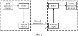
- FIG. 1 is a system framework diagram of a data transmission method according to an embodiment of this application.
- the figure shows a transmission scenario of RDMA transmission:
- a first application program reads data from a memory to generate an RDMA packet, and sends, to a local network adapter, the RDMA packet after being buffered, and then transmits the RDMA packet to a remote network adapter by using a network.
- the remote network adapter buffers the received RDMA packet, and a second application program reads data from a buffer and writes the data into a memory.
- a process in which the first application program reads the data in the memory of the second application program is similar to the foregoing description of the write process. Details are not described herein.
- the network adapter includes a host channel adapter (host channel adapter, HCA).
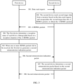
- FIG. 2 is a schematic diagram of an embodiment of a data transmission method according to a non-claimed embodiment of this application.
- an embodiment of a data transmission method according to an embodiment of this application includes the following steps.
- a first device encapsulates first target data into N RDMA packets according to an RDMA protocol, to obtain N RDMA packets.
- the first target data is data that needs to be written by the first device into a memory of a second device
- each of the N RDMA packets has a corresponding packet sequence number (packet sequence number, PSN), and N is a positive integer greater than or equal to 2.
- PSN packet sequence number
- N is a positive integer greater than or equal to 2.
- Each of the N RDMA packets carries a first data write address corresponding to the packet data. Therefore, the device may directly obtain, from each RDMA packet, the first data write address corresponding to the packet data.
- the first data write address is a type of addresses, and specific values of the addresses are different. Data write addresses corresponding to different values are substantially corresponding to different storage space. Each RDMA packet carries a value of the first data write address, to indicate different first data write addresses. Similarly, a second data address described in the following is similar to the first data address described herein. Details are not described in the following.
- the memory may be memory space of an application program in the second device, and the first target data may be data stored in memory space of an application program in the first device.
- the N RDMA packets may be specifically an RDMA write packet, and the RDMA write packet includes the following three types: an RDMA write first packet, an RDMA write middle packet, and an RDMA write last packet.
- An RDMA extended transport header (RDMA extended transport header, RETH) is a field in an RDMA packet format, and the field carries a destination address of the packet data.
- a base transport header (base transport header, BTH) is a field in the RDMA packet format, and includes a PSN.
- RDMA write First has both a BTH field and a RETH field.
- the RDMA write first packet includes a PSN and a first data write address.
- a remote direct memory access write middle packet (RDMA write Middle) and a remote direct memory access write last packet (RDMA write Last) each have only a BTH field.
- the RETH field is added to the RDMA write middle packet and the RDMA write last packet (as shown by gray parts in FIG. 9 ), so that each of the N RDMA packets carries the first data write address.
- FIG. 9(a) and FIG. 9(b) are a schematic diagram of an extended structure of a remote direct memory access write packet according to an embodiment of this application.
- FIG. 9(a) shows a frame structure of a non-extended RDMA packet.
- FIG. 9(b) shows a frame structure of an extended RDMA packet, and gray parts in FIG. 9(b) show newly added RDMA extended transport headers.
- FIG. 10 is a schematic diagram of an embodiment of an RDMA extended transport header according to an embodiment of this application. 32 bits are used as an example in FIG. 10 . It should be noted that a frame structure of another part of the packet in FIG. 9(a) and FIG. 9(b) is similar to a packet structure in the existing RDMA protocol. Details are not described herein.
- Each of the three types of RDMA write packets namely, the RDMA write first packet, RDMA write middle packet, and RDMA write last packet in this application carries the RETH field, and therefore, when receiving any one of the N RDMA packets, a receiving device may directly obtain the first data write address corresponding to the packet data, so that the packet data can be directly written into memory space of the application program without being buffered in a buffer.
- a maximum transmission unit is a maximum data packet size that can be transmitted in each RDMA transmission in the RDMA protocol, and a quantity N of the RDMA packets may be determined based on a data volume and an MTU of the first target data.
- the first device sequentially sends the N RDMA packets to the second device according to a PSN sequence of the N RDMA packets.
- a first RDMA packet is an RDMA write first packet, and a PSN of the first RDMA packet is equal to 0.
- a fifth packet is an RDMA write last packet, and a PSN of the fifth packet is equal to 4.
- Remaining three packets are RDMA write middle packets, and PSNs of the remaining three packets are respectively 1, 2, and 3.
- the first device sequentially sends the five RDMA packets to the second device according to a PSN sequence.
- the second device determines a reception status of each bit in a bitmap table based on a reception situation of the N RDMA packets.
- the reception status includes a reception success state or a reception failure state. For example, if a bit is 0, it indicates that a packet fails to be received; and if a bit is 1, it indicates that a packet is successfully received.
- the second device may specifically determine the reception status of each bit in the bitmap table based on the PSN obtained from the BTH field in the RDMA write packet.
- the second device When one or more RDMA packets fail to be received, the second device generates a first retransmission indication packet.
- the second device determines a PSN corresponding to a bit whose reception status is a reception failure state in the bitmap table as a first retransmission PSN. Then, the second device generates the first retransmission indication packet based on the first retransmission PSN, where the first retransmission indication packet is a selective indication packet, used to instruct the first device to transmit only one or more packets that are not successfully received.
- the first retransmission indication packet is used to instruct the first device to transmit only two packets whose PSNs are respectively equal to 1 and 4, and there is no need to perform transmission starting from the packet whose PSN is equal to 1 to all subsequent packets.
- a negative acknowledgment (negative acknowledgment, NACK) packet is used to instruct a transmit end to retransmit all packets starting from a specific lost packet.
- the transmit end cannot retransmit only the lost packet. Therefore, in the data transmission method in this application, a selective retransmission indication packet is newly defined by reusing an original NACK packet format: the NACK packet in the RDMA protocol includes an ACK extended transport header (acknowledgment extended transport header, AETH) field, and a definition (as shown in FIG. 11 and FIG. 12 ) of the selective retransmission indication packet is newly added to the AETH field, so that the NACK packet may instruct the first device to retransmit only an RDMA packet that fails to be received.
- AETH acknowledgement extended transport header
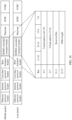
- FIG. 11 is a schematic diagram of a frame structure of an ACK extended transport header according to an embodiment of this application.
- the ACK extended transport header has 32 bits in total, where a 31 th bit to a 24 th bit indicate an acknowledgment indication field, a range of the acknowledgment indication (syndrome) field indicates information corresponding to an acknowledgment (ACK) or a negative acknowledgment (NACK), a 0 th bit to a 23 th bit indicate a message sequence number field, and the message sequence number (message sequence number, MSN) field indicates a sequence number corresponding to a message that has been transmitted in an acknowledgment response.
- ACK acknowledgment indication
- NACK negative acknowledgment
- MSN message sequence number
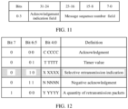
- FIG. 12 is a schematic diagram of an embodiment of a syndrome field in an ACK extended transport header according to an embodiment of this application. Compared with an existing syndrome field, gray parts in FIG. 12 indicates a newly added selective retransmission indication, in other words, bits (a 7 th bit to a 5 th bit) are in a (0 1 0) state.
- the selective retransmission indication may specifically indicate a quantity of retransmission packets and a sequence number of a start retransmission packet.
- four other states (000, 001, 011, 100) are existing states. Details are not described in this application.
- the second device sends the first retransmission indication packet to the first device.
- the second device sends the first retransmission indication packet to the first device, where the first retransmission indication packet carries the first retransmission PSN, and the first retransmission PSN is a PSN of an RDMA packet that fails to be received by the second device.
- the first device determines a first retransmission packet based on the first retransmission indication packet.
- the first device parses the first retransmission indication packet sent by the second device, to obtain the first retransmission PSN. Then, the first device determines, based on the first retransmission PSN, an RDMA packet that needs to be retransmitted in the N RDMA packets, to obtain the first retransmission packet.
- the first device sends the first retransmission packet to the second device.
- the first device sends the first retransmission packet to the second device, where the first retransmission packet includes only the RDMA packet that fails to be received by the second device.
- each RDMA packet carries a first data write address.
- the receive end can directly obtain the first data write address corresponding to the packet data, so that the receive end can store the packet data of each packet without buffering the packet data. This saves buffer space, and a lost packet does not affect learning of a data write address of a successfully received packet by the receive end, so that RDMA data transmission is insensitive to a network packet loss rate, thereby increasing network transmission efficiency and a network throughput.
- the receive end may instruct the transmit end to retransmit only lost data, so that the transmit end does not transmit another successfully received packet when retransmitting a lost packet. This can save a network transmission resource and increase network transmission efficiency.
- FIG. 3 is a schematic diagram of another embodiment of a data transmission method according to an embodiment of this application.
- FIG. 3 another embodiment of a data transmission method according to an embodiment of this application includes the following steps.
- a first device sends a data read request to a second device.
- the data read request is generated by the first device according to an RDMA protocol, and the data read request includes a data read address and a second data write address.
- the data read address is a destination address of second target data that is stored in the second device and that needs to be read by the first device
- the second data write address is a destination address used to store the second target data after the first device reads the second target data in the second device.
- the data read request may be specifically an RDMA read request in the RDMA protocol.
- a RETH field in the RDMA read request in the RDMA protocol includes the data read address, but does not include the second data write address.
- an RDMA read request packet format is redesigned (as shown in FIG.
- a RETH 2 field of a second RDMA extended transport header (the RETH 2 is used for a read operation, a format may be referred to that of the RETH, and the number 2 is used to differ from the RETH) is added to the RDMA read request packet, where the RETH 2 field carries information about the second data write address (for example, the RETH 2 field carries the information about the second data write address by using a virtual address field in FIG. 13 ).
- FIG. 13 is a schematic diagram of a frame structure of an RDMA read request and a frame structure of an RDMA read response packet according to an embodiment of this application.
- a RETH 2 field is added to both the RDMA read request and the RDMA read response packet.
- a RETH field is a field used to indicate a memory address in the RDMA protocol.
- a RETH 2 field is newly added to indicate the second data write address.
- the second data write address is a type of addresses, and specific values of the addresses may be different.
- a description of the RETH 2 field in FIG. 13 is similar to the description in FIG. 10 . For a related description, refer to the description in FIG. 10 .
- the RDMA read response packet may be specifically an RDMA read respond packet.
- the RDMA read respond packet may be classified into three types based on a packet location: an RDMA read respond first packet, an RDMA read respond middle packet, and an RDMA read respond last packet.
- the second device reads the second target data from a memory based on the data read request packet, and encapsulates the second target data into A RDMA packets, to obtain the A RDMA packets.
- the second device reads the second target data from storage space corresponding to the data read address in the data read request packet. Then, the second device encapsulates the second target data into the A RDMA packets, so that each of the A RDMA packets includes the second data write address corresponding to packet data.
- Each of the A RDMA packets includes a PSN, and A is a positive integer greater than or equal to 2.
- the A RDMA packets specifically include three types of packets: an RDMA read respond first packet, an RDMA read respond middle packet, and an RDMA read respond last packet.
- the foregoing three packets in the current RDMA do not include the second data write address corresponding to the packet data. Therefore, the foregoing three types of packets are redesigned in this application, a RETH 2 field is added to each of the three types of packets: the RDMA read respond first packet, the RDMA read respond middle packet, and the RDMA read respond last packet, so that the newly added RETH field carries the second data write address corresponding to the packet data.
- the RDMA read respond packet redesigned in this application is shown in FIG. 13 .
- step 302 is similar to the descriptions in step 201. Details are not described herein.
- the second device sequentially sends the A RDMA packets to the first device according to a PSN sequence of the A RDMA packets.
- a first RDMA packet is an RDMA read respond first packet, and a PSN of the first RDMA packet is equal to 0.
- a fifth packet is an RDMA read respond last packet, and a PSN of the fifth packet is equal to 4.
- Remaining three packets are RDMA read respond middle packets, and PSNs of the remaining three packets are respectively 1, 2, and 3.
- the second device sequentially sends the five RDMA packets to the first device according to a PSN sequence.
- the first device determines a reception status of each bit in a bitmap table based on a reception situation of the A RDMA packets.
- Step 304 is similar to the foregoing step 203, and details are not described herein. A difference lies in that the bitmap table is maintained by the first device end.
- the first device When one or more RDMA packets fail to be received, the first device generates a second retransmission indication packet.
- the first device determines a PSN corresponding to a bit whose reception status is a reception failure state in the bitmap table as a second retransmission PSN. Then, the first device generates the second retransmission indication packet based on the second retransmission PSN, where the second retransmission indication packet is a selective indication packet, used to instruct the second device to transmit only one or more packets that are not successfully received.
- the second retransmission indication packet is used to instruct the second device to transmit only two packets whose PSNs are respectively equal to 1 and 4, and there is no need to perform transmission starting from the packet whose PSN is equal to 1 to all subsequent packets.
- a definition and a related description about a selective retransmission indication packet in this step are similar to the description in the foregoing step 204. Details are not described herein.
- the first device sends the second retransmission indication packet to the second device.
- the first device sends the second retransmission indication packet to the second device, where the second retransmission indication packet carries the second retransmission PSN, and the second retransmission PSN is a PSN of an RDMA packet that fails to be received by the first device.
- the second device determines a second retransmission packet based on the second retransmission indication packet.
- the second device parses the second retransmission indication packet sent by the first device, to obtain the second retransmission PSN. Then, the second device determines, based on the second retransmission PSN, an RDMA packet that needs to be retransmitted in the A RDMA packets, to obtain the second retransmission packet.
- the second device sends the second retransmission packet to the first device.
- the second device sends the second retransmission packet to the first device, where the second retransmission packet includes only the RDMA packet that fails to be received by the first device.
- beneficial effects corresponding to the data read method are similar to beneficial effects of the data write method. Details are not described herein.
- FIG. 4 shows an embodiment of a first device 40 according to a non-claimed embodiment of this application.
- the first device 40 includes:
- a first device 50 further includes:
- any one of a second RDMA packet to an N th RDMA packet that are corresponding to the N RDMA packets carries an RDMA extended transport header, and the RDMA extended transport header is used to indicate the first data write address.
- FIG. 6 shows an embodiment of a first device 60 according to an embodiment of this application.
- the first device 60 includes:
- a network device 70 further includes: a determining module 705, configured to determine a reception status of each bit in a bitmap table of the first device based on a reception situation of the A RDMA packets, where the reception status is a reception success state or a reception failure state, and the PSN of each of the A RDMA packets is corresponding to one bit in the bitmap table of the first device.
- a determining module 705 configured to determine a reception status of each bit in a bitmap table of the first device based on a reception situation of the A RDMA packets, where the reception status is a reception success state or a reception failure state, and the PSN of each of the A RDMA packets is corresponding to one bit in the bitmap table of the first device.
- the determining module 705 is further configured to:
- the retransmission PSN is indicated by using an ACK extended transport header field in a negative acknowledgment packet defined in the RDMA protocol.
- the data read request carries a second RDMA extended transport header field, and the second RDMA extended transport header field is used to indicate the second data write address.
- FIG. 8 is a schematic diagram of a hardware structure of a first device according to a non-claimed embodiment of this application.
- the first device includes: a receiver 801, a transmitter 802, a processor 803, a memory 804, and a bus 805.
- the memory 804 may include a read-only memory and a random access memory, and provide an instruction and data to the processor 803.
- a part of the memory 804 may further include a non-volatile random access memory (non-volatile random access memory, NVRAM).
- the memory 804 stores the following elements: an executable module or a data structure, a subset thereof, or an extended set thereof.
- Operation instructions include various operation instructions and used to implement various operations.
- Operating systems include various system programs and used to implement various basic services and process a hardware-based task.
- the processor 803 in this embodiment of this application may be configured to perform operations corresponding to the first device in the embodiment corresponding to FIG. 2 , and the operations may include the following operations: encapsulating first target data into N RDMA packets according to a remote direct memory access RDMA protocol, where the first target data is data that needs to be written by the first device into a second device for storage, any one of the N RDMA packets carries a packet sequence number PSN, and N is a positive integer greater than or equal to 2; sequentially sending the N RDMA packets to the second device according to a PSN sequence of the N RDMA packets, where each of the N RDMA packets carries a first data write address, and the first data write address is an address for writing data in each of the N RDMA packets into the second device, so that the second device directly obtains the first data write address in each RDMA packet from the RDMA packet, and writes the target data into storage space corresponding to the first data write address.
- the processor 803 is further configured to perform other related operations in the embodiment corresponding to FIG. 2 .
- the processor 803 is further configured to perform other related operations in the embodiment corresponding to FIG. 2 .
- the processor 803 may be configured to perform operations corresponding to the first device in the embodiment corresponding to FIG. 3 , and the operations may include the following operations: sending a data read request to a second device, where the data read request is generated according to a remote direct memory access RDMA protocol, and carries a data read address and a second data write address, the data read address is a destination address of second target data stored in the second device, the second data write address is a destination address that is reserved in the first device and that is used to store the second target data read from the second device, and the second target data is data that needs to be read by the first device from the second device;
- the operations may include the following operations: sending a data read request to a second device, where the data read request is generated according to a remote direct memory access RDMA protocol, and carries a data read address and a second data write address, the data read address is a destination address of second target data stored in the second device, the second data write address is a destination address that is reserved in the first device and that is
- the processor 803 is further configured to perform other related operations in the embodiment corresponding to FIG. 3 .
- the processor 803 is further configured to perform other related operations in the embodiment corresponding to FIG. 3 .
- the processor 803 controls an operation of the first device, and the processor 803 may also be referred to as a central processing unit (central processing unit, CPU).
- the memory 804 may include a read-only memory and a random access memory, and provide an instruction and data to the processor 803. A part of the memory 804 may further include an NVRAM.
- components of the first device are coupled together by using a bus system 805, where the bus system 805 may further include a power bus, a control bus, a state signal bus, and the like in addition to a data bus.
- various buses are marked as the bus system 805 in the figure.
- the methods disclosed in the foregoing embodiments of this application may be applied to the processor 803, or may be implemented by the processor 803.
- the processor 803 may be an integrated circuit chip and has a signal processing capability. In an implementation process, the steps in the foregoing methods may be accomplished by using a hardware integrated logic circuit in the processor 803, or by using instructions in a form of software.
- the processor 803 may be a general-purpose processor, a digital signal processor (digital signal processing, DSP), an application-specific integrated circuit (application specific integrated circuit, ASIC), a field programmable gate array (field-programmable gate array, FPGA) or another programmable logic device, a discrete gate or a transistor logic device, or a discrete hardware component.
- the processor may implement or perform the methods, the steps, and the logical block diagrams that are disclosed in the embodiments of this application.
- the general-purpose processor may be a microprocessor, or the processor may be any conventional processor, or the like.
- the steps of the methods disclosed with reference to the embodiments of this application may be directly executed and accomplished by a hardware decoding processor, or executed and accomplished by using a combination of hardware and a software module in a decoding processor.
- the software module may be located in a mature storage medium in the art, such as a random access memory, a flash memory, a read-only memory, a programmable read-only memory, an electrically erasable programmable memory, a register, or the like.
- the storage medium is located in the memory 804, and the processor 803 reads information in the memory 804 and accomplishes the steps of the foregoing methods in combination with the hardware of the processor 803.
- FIG. 8 For a related description of FIG. 8 , refer to related descriptions and effects of the methods in FIG. 2 and FIG. 3 for understanding. Details are not described herein.
- a non-claimed embodiment of this application further provides a computer storage medium, configured to store a computer software instruction used by the foregoing first device.
- the computer software instruction When the computer software instruction is run on a computer, the computer is enabled to perform the data transmission methods performed by the first device in the embodiments in FIG. 2 and FIG. 3 .
- the storage medium may be specifically the foregoing memory 804.
- a non-claimed embodiment of this application further provides a computer program product including an instruction.
- the computer program product When the computer program product is run on a computer, the computer is enabled to perform the data transmission method performed by the first device.
- a non-claimed embodiment of this application further provides a network interface processing circuit.
- the network interface processing circuit includes a processing circuit and a communications interface circuit.
- the communications interface circuit is configured to perform a data sending and receiving operation, and the processing circuit is configured to perform the data transmission methods in FIG. 2 and FIG. 3 .
- the processing circuit may be specifically an application-specific integrated circuit (ASIC), or may be a field programmable gate array (FPGA) or another programmable logic device, a discrete gate or a transistor logic device, or a discrete hardware component.
- ASIC application-specific integrated circuit
- FPGA field programmable gate array
- a non-claimed embodiment of this application further provides a network adapter.
- the network adapter includes a network interface chip, a memory, and a host interface circuit.
- the memory is configured to store a computer operation instruction
- the host interface circuit is configured to connect a host and the network adapter
- the network interface chip is configured to perform the data transmission methods in FIG. 2 and FIG. 3 by invoking the computer operation instruction.
- the memory may be a buffer.
- a non-claimed embodiment of this application further provides a network device.
- the network device includes a network adapter, a host, and a memory.
- the network adapter may be the network adapter in the foregoing embodiment, the memory is configured to store a computer operation instruction, the network adapter is configured to receive or send data, and the host is configured to perform the data transmission methods in FIG. 2 and FIG. 3 by invoking the computer operation instruction.
- the network device may be specifically a server.
- the disclosed system, apparatus, and method may be implemented in other manners.
- the described apparatus embodiments are merely examples.
- division into the units is merely logical function division and may be other division in actual implementation.
- a plurality of units or components may be combined or integrated into another system, or some features may be ignored or not performed.
- the displayed or discussed mutual couplings or direct couplings or communication connections may be implemented by using some interfaces.
- the indirect couplings or communication connections between the apparatuses or units may be implemented in electrical, mechanical, or another form.
- the units described as separate parts may or may not be physically separate, and components displayed as units may or may not be physical units.
- the components may be located in one position, or may be distributed on a plurality of network units. Some or all of the units may be selected based on actual requirements to achieve the objectives of the solutions in the embodiments.
- functional units in the embodiments of this application may be integrated into one processing unit, or each of the units may exist alone physically, or two or more units may be integrated into one unit.
- the integrated unit may be implemented in a form of hardware, or may be implemented in a form of a software functional unit.
- the integrated unit When the integrated unit is implemented in the form of a software functional unit and sold or used as an independent product, the integrated unit may be stored in a computer-readable storage medium. Based on such an understanding, the technical solutions of this application essentially, or the part contributing to the prior art, or all or some of the technical solutions may be implemented in a form of a software product.
- the computer software product is stored in a storage medium and includes several instructions for instructing a computer device (which may be a personal computer, a server, a network device, or the like) to perform all or some of the steps of the methods described in the embodiments of this application.
- the storage medium includes any medium that can store program code, for example, a USB flash drive, a removable hard disk, a read-only memory (read-only memory, ROM), a random access memory (random access memory, RAM), a magnetic disk, or an optical disc.
- program code for example, a USB flash drive, a removable hard disk, a read-only memory (read-only memory, ROM), a random access memory (random access memory, RAM), a magnetic disk, or an optical disc.
Landscapes
- Engineering & Computer Science (AREA)
- Computer Networks & Wireless Communication (AREA)
- Signal Processing (AREA)
- Theoretical Computer Science (AREA)
- Physics & Mathematics (AREA)
- General Engineering & Computer Science (AREA)
- General Physics & Mathematics (AREA)
- Computer Security & Cryptography (AREA)
- Computer Hardware Design (AREA)
- Software Systems (AREA)
- Mathematical Physics (AREA)
- Communication Control (AREA)
- Detection And Prevention Of Errors In Transmission (AREA)
- Computer And Data Communications (AREA)
- Small-Scale Networks (AREA)
Description
- This disclosure relates to the field of network communications technologies, and the invention in particular relates to a data transmission method and a first device constituting a network device.
- Priority-based flow control (priority-based flow control, PFC) is a flow control mechanism for enhancing a conventional Ethernet flow control mechanism, avoiding a packet loss, and increasing a network throughput. A PFC flow control mechanism can effectively reduce a network packet loss rate, but may cause problems such as PFC congestion spreading, a PFC deadlock, a PFC storm, and a PFC transmission distance limitation, thereby reducing network transmission reliability.
- A remote direct memory access (remote direct memory access, RDMA) protocol is a protocol by using which data is directly transmitted from a system to a memory of another system by using a network without intervention of an operating system. In the RDMA protocol, to-be-transmitted data is encapsulated into one or more RDMA packets, and the one or more RDMA packets are sent from a transmit end to a receive end. The receive end buffers the received RDMA packet into a buffer. When the receive end successfully receives all RDMA packets of the to-be-transmitted data, the receive end writes buffered data in the buffer into a memory of the receive end.
- According to the RDMA protocol, a Go-Back-N retransmission mechanism is used to retransmit a lost packet. The Go-Back-N retransmission mechanism is a retransmission mechanism in which network transmission efficiency is greatly decreased even though a packet loss rate is very low. Therefore, the RDMA protocol is very sensitive to the packet loss rate. The RDMA protocol is generated to resolve a problem of a delay of data transmission between server sides during network communications. Because there is almost no packet loss during the data transmission between the server sides during the network communications, and the packet loss rate during the data transmission is very low, the RDMA protocol is used to effectively resolve the problem of the delay of the transmission between the server sides during the network communications.
- The RDMA protocol can run on a plurality of data link layer protocols such as the Ethernet. With development of the RDMA protocol, the RDMA protocol is gradually applied to the Ethernet. In this case, the problem that the RDMA protocol is sensitive to the packet loss rate gradually emerges. When the RDMA protocol is applied to the Ethernet for data transmission, a network device in the Ethernet needs to enable the PFC flow control mechanism, to reduce impact of the network packet loss on the network transmission efficiency. However, with the PFC flow control mechanism is enabled, the network transmission reliability is reduced accordingly.
-
US 2015/172226 A1 discloses a method for communication, which includes receiving at a receiving node over a network from a sending node a succession of data packets belonging to a sequence of transactions, including at least one or more first packets belonging to a first transaction and one or more second packets belonging to a second transaction executed by the sending node after the first transaction, wherein at least one of the second packets is received at the receiving node before at least one of the first packets. At the receiving node, upon receipt of the data packets, data are written from the data packets in the succession to respective locations in a buffer. Execution of the second transaction at the receiving node is delayed until all of the first packets have been received and the first transaction has been executed at the receiving node. -
US 2015/039712 A1 discloses one or more remote nodes with direct access to persistent random access memory (PRAM). In an embodiment, registration information is generated for a remote direct access enabled network interface controller (RNIC). The registration information associates an access key with a target region in PRAM. The access key is sent to a remote node of the one or more nodes. The RNIC may subsequently receive a remote direct memory access (RDMA) message from the remote node that includes the access key. In response to the RDMA message, the RNIC performs a direct memory access within the target region of PRAM. - XP 058371641 discloses MELO, and efficient selective retransmission mechanism for hardware-based transport, which consumes only a constant small memory regardless of the number of concurrent connections.
- The object of the present invention is to provide a data transmission method and a first device, to reduce impact of a network packet loss on network transmission efficiency and improve network transmission reliability. This object is solved by a data transmission method of
claim 1 and a first device according toclaim 5. Further advantageous embodiments and improvements of the present invention are listed in the dependent claims. Aspects which contribute to the understanding of the invention are listed hereinafter. However, it should be noted that the invention is defined by the attached claims and any examples and embodiments not covered by these claims are also understood as aspects contributing to the understanding of the invention. - According to a first aspect, this disclosure provides a data transmission method, including:
- sending, by a first device, a data read request to a second device, where the data read request is generated according to a remote direct memory access RDMA protocol, and carries a data read address and a second data write address, the data read address is a destination address of second target data stored in the second device, the second data write address is a destination address that is reserved in the first device and that is used to store the second target data read from the second device, the second target data is data that needs to be read by the first device from the second device, the data read request is an RDMA read request, and the RDMA read request comprises two RDMA extended transport header, RETH, fields separately carrying the data read address and the second data write address; and
- receiving, by the first device, B RDMA packets from A RDMA packets sequentially sent by the second device according to a PSN sequence of the A RDMA packets, where the A RDMA packets are obtained by the second device by encapsulating the second target data read from the data read address, each of the A RDMA packets carries a packet sequence number PSN, A is a positive integer greater than or equal to 2, each of the A RDMA packets includes the second data write address corresponding to data of the packet, the A RDMA packets comprises three types of packets: an RDMA read respond first packet, an RDMA read respond middle packet and an RDMA read respond last packet, and the three types of packets comprise RETH field carrying the second data write address; and
- directly obtaining, by the first device, the second data write address of each RDMA packet from each of the successfully received B RDMA packets, where B is a positive integer less than or equal to A; and
- writing, by the first device, data of each of the B RDMA packets into storage space of the second data write address corresponding to the RDMA packet.
- With reference to the first aspect of this disclosure, in a first possible implementation of the first aspect of this application, after the receiving, by the first device, B RDMA packets from A RDMA packets sequentially sent by the second device according to a PSN sequence of the A RDMA packets, the method further includes:
determining, by the first device, a reception status of each bit in a bitmap table of the first device based on a reception situation of the A RDMA packets, where the reception status is a reception success state or a reception failure state, and the PSN of each of the A RDMA packets is corresponding to one bit in the bitmap table of the first device. - With reference to the first aspect of this disclosure or the first possible implementation of the first aspect of this disclosure, in a second possible implementation of the second aspect of this application, after the receiving, by the first device, B RDMA packets from A RDMA packets sequentially sent by the second device according to a PSN sequence of the A RDMA packets, the method further includes:
- when B is less than A, determining, by the first device, a PSN corresponding to a bit whose reception status is a reception failure state in the bitmap of the first device as a retransmission PSN;
- sending, by the first device, a retransmission indication packet to the second device, where the retransmission indication packet carries the retransmission PSN; and
- receiving, by the first device, a retransmission packet sent by the second device based on the retransmission indication packet, where the retransmission packet is an RDMA packet that failed to be received and that is corresponding to the retransmission PSN.
- With reference to the second possible implementation of the first aspect of this disclosure, in a third possible implementation of the first aspect of this application, the retransmission PSN is indicated by using an ACK extended transport header field in a negative acknowledgment packet defined in the RDMA protocol.
- According to a second aspect, this disclosure provides a network device configured to perform the data transmission method according to the first aspect.
-
-
FIG. 1 is a system framework diagram of a data transmission method; -
FIG. 2 is a schematic diagram of an embodiment of a data transmission method; -
FIG. 3 is a schematic diagram of another embodiment of a data transmission method according to an embodiment of this application; -
FIG. 4 is a schematic diagram of an embodiment of a first device; -
FIG. 5 is a schematic diagram of another embodiment of a first device; -
FIG. 6 is a schematic diagram of still another embodiment of a first device according to an embodiment of this application; -
FIG. 7 is a schematic diagram of yet another embodiment of a first device; -
FIG. 8 is a schematic diagram of a hardware structure of a first device; -
FIG. 9(a) and FIG. 9(b) are a schematic diagram of an extended structure of an RDMA packet; -
FIG. 10 is a schematic diagram of an embodiment of an RDMA extended transport header; -
FIG. 11 is a schematic diagram of a frame structure of an ACK extended transport header; -
FIG. 12 is a schematic diagram of an embodiment of a syndrome field in an ACK extended transport header; and -
FIG. 13 is a schematic diagram of a frame structure of an RDMA read request and a frame structure of an RDMA read response packet according to an embodiment of this application. - This application provides a data transmission method and a first device, to reduce impact of a network packet loss on network transmission efficiency and improve network transmission reliability. The following clearly and completely describes the technical solutions in this application with reference to the accompanying drawings in this application. Apparently, the described embodiments are merely some embodiments rather than all of the embodiments in this application.
- In this specification, claims, and accompanying drawings of this application, the terms "first", "second", "third", "fourth", and the like (if existent) are intended to distinguish between similar objects but do not necessarily indicate a specific order or sequence. It should be understood that data used in such a way is interchangeable in proper a circumstance so that the embodiments described herein can be implemented in other orders than the order illustrated or described herein. In addition, the terms "include", "have", and any other variants mean to cover non-exclusive inclusion, for example, a process, method, system, product, or device that includes a list of steps or units is not necessarily limited to those expressly listed steps or units, but may include other steps or units that are not expressly listed or inherent to such a process, method, product, or device.
- The data transmission method in the embodiments of this application is mainly applicable to an RDMA transmission application scenario, and is particularly applicable to some network transmission scenarios in which a packet loss rate is comparatively high and a network transmission scenario in which network transmission reliability is reduced because a PFC flow control mechanism is enabled, such as a scenario in which an RDMA protocol is converged into the conventional Ethernet for data transmission. According to the data transmission method in the embodiments of this application, a data transmission problem in the foregoing application scenario can be effectively resolved, thereby increasing network transmission efficiency and improving network transmission reliability.
- When an application program initiates an RDMA read/write request, a system does not perform a data replication action. This reduces times of context switching between kernel space and user space during network communications processing. In a condition that no kernel memory is required to participate, an RDMA request is sent to a local network adapter from an application program running in user space, and then is transmitted to a remote adapter by using a network. An operating system does not need to participate in RDMA transmission, so that system load is not increased.
FIG. 1 is a system framework diagram of a data transmission method according to an embodiment of this application. The figure shows a transmission scenario of RDMA transmission: A first application program reads data from a memory to generate an RDMA packet, and sends, to a local network adapter, the RDMA packet after being buffered, and then transmits the RDMA packet to a remote network adapter by using a network. The remote network adapter buffers the received RDMA packet, and a second application program reads data from a buffer and writes the data into a memory. Similarly, a process in which the first application program reads the data in the memory of the second application program is similar to the foregoing description of the write process. Details are not described herein. In addition, the network adapter includes a host channel adapter (host channel adapter, HCA). - To facilitate understanding of the data transmission method in the embodiments of this application, the following describes the data transmission method in the embodiments of this application in detail from two aspects: data write and data read. Details are as follows.
-
FIG. 2 is a schematic diagram of an embodiment of a data transmission method according to a non-claimed embodiment of this application. - As shown in
FIG. 2 , an embodiment of a data transmission method according to an embodiment of this application includes the following steps. - 201. A first device encapsulates first target data into N RDMA packets according to an RDMA protocol, to obtain N RDMA packets.
- The first target data is data that needs to be written by the first device into a memory of a second device, each of the N RDMA packets has a corresponding packet sequence number (packet sequence number, PSN), and N is a positive integer greater than or equal to 2. Each of the N RDMA packets carries a first data write address corresponding to the packet data. Therefore, the device may directly obtain, from each RDMA packet, the first data write address corresponding to the packet data.
- The first data write address is a type of addresses, and specific values of the addresses are different. Data write addresses corresponding to different values are substantially corresponding to different storage space. Each RDMA packet carries a value of the first data write address, to indicate different first data write addresses. Similarly, a second data address described in the following is similar to the first data address described herein. Details are not described in the following.
- The memory may be memory space of an application program in the second device, and the first target data may be data stored in memory space of an application program in the first device.
- The N RDMA packets may be specifically an RDMA write packet, and the RDMA write packet includes the following three types: an RDMA write first packet, an RDMA write middle packet, and an RDMA write last packet. An RDMA extended transport header (RDMA extended transport header, RETH) is a field in an RDMA packet format, and the field carries a destination address of the packet data. A base transport header (base transport header, BTH) is a field in the RDMA packet format, and includes a PSN. In an existing remote direct memory access write (RDMA write) packet, a remote direct memory access write first packet (RDMA write First) has both a BTH field and a RETH field. Therefore, the RDMA write first packet includes a PSN and a first data write address. However, a remote direct memory access write middle packet (RDMA write Middle) and a remote direct memory access write last packet (RDMA write Last) each have only a BTH field. Based on the foregoing packet format, in the data transmission method in this application, the RETH field is added to the RDMA write middle packet and the RDMA write last packet (as shown by gray parts in
FIG. 9 ), so that each of the N RDMA packets carries the first data write address.FIG. 9(a) and FIG. 9(b) are a schematic diagram of an extended structure of a remote direct memory access write packet according to an embodiment of this application.FIG. 9(a) shows a frame structure of a non-extended RDMA packet.FIG. 9(b) shows a frame structure of an extended RDMA packet, and gray parts inFIG. 9(b) show newly added RDMA extended transport headers. Further,FIG. 10 is a schematic diagram of an embodiment of an RDMA extended transport header according to an embodiment of this application. 32 bits are used as an example inFIG. 10 . It should be noted that a frame structure of another part of the packet inFIG. 9(a) and FIG. 9(b) is similar to a packet structure in the existing RDMA protocol. Details are not described herein. - Each of the three types of RDMA write packets, namely, the RDMA write first packet, RDMA write middle packet, and RDMA write last packet in this application carries the RETH field, and therefore, when receiving any one of the N RDMA packets, a receiving device may directly obtain the first data write address corresponding to the packet data, so that the packet data can be directly written into memory space of the application program without being buffered in a buffer.
- A maximum transmission unit (maximum transmission unit, MTU) is a maximum data packet size that can be transmitted in each RDMA transmission in the RDMA protocol, and a quantity N of the RDMA packets may be determined based on a data volume and an MTU of the first target data.
- 202. The first device sequentially sends the N RDMA packets to the second device according to a PSN sequence of the N RDMA packets.
- For example, five RDMA packets are obtained based on
step 201. A first RDMA packet is an RDMA write first packet, and a PSN of the first RDMA packet is equal to 0. A fifth packet is an RDMA write last packet, and a PSN of the fifth packet is equal to 4. Remaining three packets are RDMA write middle packets, and PSNs of the remaining three packets are respectively 1, 2, and 3. The first device sequentially sends the five RDMA packets to the second device according to a PSN sequence. - 203. The second device determines a reception status of each bit in a bitmap table based on a reception situation of the N RDMA packets.
- For each RDMA transmission, a one-to-one mapping relationship is established between the N RDMA packets and the bitmap table by using PSNs, and one PSN is corresponding to one bit. The reception status includes a reception success state or a reception failure state. For example, if a bit is 0, it indicates that a packet fails to be received; and if a bit is 1, it indicates that a packet is successfully received.
- The second device may specifically determine the reception status of each bit in the bitmap table based on the PSN obtained from the BTH field in the RDMA write packet.
- 204. When one or more RDMA packets fail to be received, the second device generates a first retransmission indication packet.
- When one or more RDMA packets in the N packets fail to be received, the second device determines a PSN corresponding to a bit whose reception status is a reception failure state in the bitmap table as a first retransmission PSN. Then, the second device generates the first retransmission indication packet based on the first retransmission PSN, where the first retransmission indication packet is a selective indication packet, used to instruct the first device to transmit only one or more packets that are not successfully received. For example, if a packet whose PSN is equal to 1 and a packet whose PSN is equal to 4 fail to be received, the first retransmission indication packet is used to instruct the first device to transmit only two packets whose PSNs are respectively equal to 1 and 4, and there is no need to perform transmission starting from the packet whose PSN is equal to 1 to all subsequent packets.
- In the RDMA protocol, a negative acknowledgment (negative acknowledgment, NACK) packet is used to instruct a transmit end to retransmit all packets starting from a specific lost packet. The transmit end cannot retransmit only the lost packet. Therefore, in the data transmission method in this application, a selective retransmission indication packet is newly defined by reusing an original NACK packet format: the NACK packet in the RDMA protocol includes an ACK extended transport header (acknowledgment extended transport header, AETH) field, and a definition (as shown in
FIG. 11 and FIG. 12 ) of the selective retransmission indication packet is newly added to the AETH field, so that the NACK packet may instruct the first device to retransmit only an RDMA packet that fails to be received. -
FIG. 11 is a schematic diagram of a frame structure of an ACK extended transport header according to an embodiment of this application. As shown inFIG. 11 , the ACK extended transport header has 32 bits in total, where a 31th bit to a 24th bit indicate an acknowledgment indication field, a range of the acknowledgment indication (syndrome) field indicates information corresponding to an acknowledgment (ACK) or a negative acknowledgment (NACK), a 0th bit to a 23th bit indicate a message sequence number field, and the message sequence number (message sequence number, MSN) field indicates a sequence number corresponding to a message that has been transmitted in an acknowledgment response. Further, as described above, in this embodiment of this application, the selective retransmission indication is newly added to the ACK extended transport header (AETH) field. Specifically,FIG. 12 is a schematic diagram of an embodiment of a syndrome field in an ACK extended transport header according to an embodiment of this application. Compared with an existing syndrome field, gray parts inFIG. 12 indicates a newly added selective retransmission indication, in other words, bits (a 7th bit to a 5th bit) are in a (0 1 0) state. Optionally, the selective retransmission indication may specifically indicate a quantity of retransmission packets and a sequence number of a start retransmission packet. In addition to the foregoing (0 1 0) state that is a newly added indication state, four other states (000, 001, 011, 100) are existing states. Details are not described in this application. - 205. The second device sends the first retransmission indication packet to the first device.
- The second device sends the first retransmission indication packet to the first device, where the first retransmission indication packet carries the first retransmission PSN, and the first retransmission PSN is a PSN of an RDMA packet that fails to be received by the second device.
- 206. The first device determines a first retransmission packet based on the first retransmission indication packet.
- First, the first device parses the first retransmission indication packet sent by the second device, to obtain the first retransmission PSN. Then, the first device determines, based on the first retransmission PSN, an RDMA packet that needs to be retransmitted in the N RDMA packets, to obtain the first retransmission packet.
- 207. The first device sends the first retransmission packet to the second device.
- The first device sends the first retransmission packet to the second device, where the first retransmission packet includes only the RDMA packet that fails to be received by the second device.
- In this embodiment, each RDMA packet carries a first data write address. After receiving the RDMA packet, the receive end can directly obtain the first data write address corresponding to the packet data, so that the receive end can store the packet data of each packet without buffering the packet data. This saves buffer space, and a lost packet does not affect learning of a data write address of a successfully received packet by the receive end, so that RDMA data transmission is insensitive to a network packet loss rate, thereby increasing network transmission efficiency and a network throughput.
- In a retransmission process, the receive end may instruct the transmit end to retransmit only lost data, so that the transmit end does not transmit another successfully received packet when retransmitting a lost packet. This can save a network transmission resource and increase network transmission efficiency.
-
FIG. 3 is a schematic diagram of another embodiment of a data transmission method according to an embodiment of this application. - As shown in
FIG. 3 , another embodiment of a data transmission method according to an embodiment of this application includes the following steps. - 301. A first device sends a data read request to a second device.
- The data read request is generated by the first device according to an RDMA protocol, and the data read request includes a data read address and a second data write address. The data read address is a destination address of second target data that is stored in the second device and that needs to be read by the first device, and the second data write address is a destination address used to store the second target data after the first device reads the second target data in the second device.
- The data read request may be specifically an RDMA read request in the RDMA protocol. Currently, a RETH field in the RDMA read request in the RDMA protocol includes the data read address, but does not include the second data write address. In this application, an RDMA read request packet format is redesigned (as shown in
FIG. 13 ), and aRETH 2 field of a second RDMA extended transport header (theRETH 2 is used for a read operation, a format may be referred to that of the RETH, and thenumber 2 is used to differ from the RETH) is added to the RDMA read request packet, where theRETH 2 field carries information about the second data write address (for example, theRETH 2 field carries the information about the second data write address by using a virtual address field inFIG. 13 ). -
FIG. 13 is a schematic diagram of a frame structure of an RDMA read request and a frame structure of an RDMA read response packet according to an embodiment of this application. As shown in gray parts inFIG. 13 , aRETH 2 field is added to both the RDMA read request and the RDMA read response packet. A RETH field is a field used to indicate a memory address in the RDMA protocol. In other words, aRETH 2 field is newly added to indicate the second data write address. The second data write address is a type of addresses, and specific values of the addresses may be different. A description of theRETH 2 field inFIG. 13 is similar to the description inFIG. 10 . For a related description, refer to the description inFIG. 10 . Optionally, the RDMA read response packet may be specifically an RDMA read respond packet. The RDMA read respond packet may be classified into three types based on a packet location: an RDMA read respond first packet, an RDMA read respond middle packet, and an RDMA read respond last packet. - 302. The second device reads the second target data from a memory based on the data read request packet, and encapsulates the second target data into A RDMA packets, to obtain the A RDMA packets.
- First, the second device reads the second target data from storage space corresponding to the data read address in the data read request packet. Then, the second device encapsulates the second target data into the A RDMA packets, so that each of the A RDMA packets includes the second data write address corresponding to packet data. Each of the A RDMA packets includes a PSN, and A is a positive integer greater than or equal to 2.
- The A RDMA packets specifically include three types of packets: an RDMA read respond first packet, an RDMA read respond middle packet, and an RDMA read respond last packet. However, the foregoing three packets in the current RDMA do not include the second data write address corresponding to the packet data. Therefore, the foregoing three types of packets are redesigned in this application, a
RETH 2 field is added to each of the three types of packets: the RDMA read respond first packet, the RDMA read respond middle packet, and the RDMA read respond last packet, so that the newly added RETH field carries the second data write address corresponding to the packet data. The RDMA read respond packet redesigned in this application is shown inFIG. 13 . - Other related descriptions of
step 302 are similar to the descriptions instep 201. Details are not described herein. - 303. The second device sequentially sends the A RDMA packets to the first device according to a PSN sequence of the A RDMA packets.
- For example, five RDMA packets are obtained based on
step 302. A first RDMA packet is an RDMA read respond first packet, and a PSN of the first RDMA packet is equal to 0. A fifth packet is an RDMA read respond last packet, and a PSN of the fifth packet is equal to 4. Remaining three packets are RDMA read respond middle packets, and PSNs of the remaining three packets are respectively 1, 2, and 3. The second device sequentially sends the five RDMA packets to the first device according to a PSN sequence. - 304. The first device determines a reception status of each bit in a bitmap table based on a reception situation of the A RDMA packets.
- Step 304 is similar to the foregoing step 203, and details are not described herein. A difference lies in that the bitmap table is maintained by the first device end.
- 305. When one or more RDMA packets fail to be received, the first device generates a second retransmission indication packet.
- When one or more RDMA packets in the A packets fail to be received, the first device determines a PSN corresponding to a bit whose reception status is a reception failure state in the bitmap table as a second retransmission PSN. Then, the first device generates the second retransmission indication packet based on the second retransmission PSN, where the second retransmission indication packet is a selective indication packet, used to instruct the second device to transmit only one or more packets that are not successfully received. For example, if a packet whose PSN is equal to 1 and a packet whose PSN is equal to 4 fail to be received, the second retransmission indication packet is used to instruct the second device to transmit only two packets whose PSNs are respectively equal to 1 and 4, and there is no need to perform transmission starting from the packet whose PSN is equal to 1 to all subsequent packets.
- A definition and a related description about a selective retransmission indication packet in this step are similar to the description in the foregoing
step 204. Details are not described herein. - 306. The first device sends the second retransmission indication packet to the second device.
- The first device sends the second retransmission indication packet to the second device, where the second retransmission indication packet carries the second retransmission PSN, and the second retransmission PSN is a PSN of an RDMA packet that fails to be received by the first device.
- 307. The second device determines a second retransmission packet based on the second retransmission indication packet.
- First, the second device parses the second retransmission indication packet sent by the first device, to obtain the second retransmission PSN. Then, the second device determines, based on the second retransmission PSN, an RDMA packet that needs to be retransmitted in the A RDMA packets, to obtain the second retransmission packet.
- 308. The second device sends the second retransmission packet to the first device.
- The second device sends the second retransmission packet to the first device, where the second retransmission packet includes only the RDMA packet that fails to be received by the first device.
- In this embodiment, beneficial effects corresponding to the data read method are similar to beneficial effects of the data write method. Details are not described herein.
-
FIG. 4 shows an embodiment of afirst device 40 according to a non-claimed embodiment of this application. Thefirst device 40 includes: - an
encapsulating module 401, configured to encapsulate first target data into N RDMA packets according to a remote direct memory access RDMA protocol, where the first target data is data that needs to be written by the first device into a second device for storage, any one of the N RDMA packets carries a packet sequence number PSN, and N is a positive integer greater than or equal to 2; and - a sending
module 402, configured to sequentially send the N RDMA packets to the second device according to a PSN sequence of the N RDMA packets, where each of the N RDMA packets carries a first data write address, and the first data write address is an address for writing data in each of the N RDMA packets into the second device, so that the second device directly obtains the first data write address in each RDMA packet from the RDMA packet, and writes the target data into storage space corresponding to the first data write address. - In an example, as shown in
FIG. 5 , afirst device 50 further includes: - a
receiving module 503, configured to: if the N RDMA packets are not all successfully received by the second device, receive a first retransmission indication packet sent by the second device, where the retransmission indication packet carries a retransmission PSN, the retransmission PSN is a PSN corresponding to a bit whose reception status is a reception failure state in a bitmap table of the second device, and a PSN of each of the N RDMA packets is corresponding to one bit in the bitmap table; and - a sending
module 502, further configured to send a first retransmission packet to the second device, where the first retransmission packet is an RDMA packet that fails to be received and that is corresponding to the first retransmission PSN, so that the second device stores data in the first retransmission packet into the second device. - In an example, any one of a second RDMA packet to an Nth RDMA packet that are corresponding to the N RDMA packets carries an RDMA extended transport header, and the RDMA extended transport header is used to indicate the first data write address.
-
FIG. 6 shows an embodiment of afirst device 60 according to an embodiment of this application. Thefirst device 60 includes: - a sending
module 601, configured to send a data read request packet to a second device, where the data read request packet is generated according to a remote direct memory access RDMA protocol, and carries a data read address and a second data write address, the data read address is a destination address of second target data stored in the second device, the second data write address is a destination address that is reserved in the first device and that is used to store the second target data read from the second device, and the second target data is data that needs to be read by the first device from the second device; - a
receiving module 602, configured to receive A RDMA packets sequentially sent by the second device according to a PSN sequence of the A RDMA packets, where the A RDMA packets are obtained by the second device by encapsulating the second target data read from the data read address, each of the A RDMA packets carries a packet sequence number PSN, A is a positive integer greater than or equal to 2, and each of the A RDMA packets includes the second data write address corresponding to data of the packet; - an obtaining
module 603, configured to directly obtain the second data write address of each RDMA packet from each of successfully received B RDMA packets, where B is a positive integer less than or equal to A; and - a
data write module 604, configured to write data of each of the B RDMA packets into storage space of the second data write address corresponding to the RDMA packet. - In an example, as shown in
FIG. 7 , anetwork device 70 further includes:
a determiningmodule 705, configured to determine a reception status of each bit in a bitmap table of the first device based on a reception situation of the A RDMA packets, where the reception status is a reception success state or a reception failure state, and the PSN of each of the A RDMA packets is corresponding to one bit in the bitmap table of the first device. - In another example, the determining
module 705 is further configured to: - when B is less than A, determine a PSN corresponding to a bit whose reception status is a reception failure state in the bitmap of the first device as a second retransmission PSN;
- a sending
module 701 is further configured to send a second retransmission indication packet to the second device, where the second retransmission indication packet carries the second retransmission PSN; and - a
receiving module 702 is further configured to receive a second retransmission packet sent by the second device based on the second retransmission indication packet, where the second retransmission packet is an RDMA packet that fails to be received and that is corresponding to the second retransmission PSN. - In an example, the retransmission PSN is indicated by using an ACK extended transport header field in a negative acknowledgment packet defined in the RDMA protocol.
- In an example, the data read request carries a second RDMA extended transport header field, and the second RDMA extended transport header field is used to indicate the second data write address.
- For other related descriptions and beneficial effects in this embodiment, refer to the descriptions of the first device in the embodiments corresponding to
FIG. 2 andFIG. 3 . Details are not described herein. -
FIG. 8 is a schematic diagram of a hardware structure of a first device according to a non-claimed embodiment of this application. The first device includes: areceiver 801, atransmitter 802, aprocessor 803, amemory 804, and abus 805. - The
memory 804 may include a read-only memory and a random access memory, and provide an instruction and data to theprocessor 803. A part of thememory 804 may further include a non-volatile random access memory (non-volatile random access memory, NVRAM). - The
memory 804 stores the following elements: an executable module or a data structure, a subset thereof, or an extended set thereof. - Operation instructions include various operation instructions and used to implement various operations.
- Operating systems include various system programs and used to implement various basic services and process a hardware-based task.
- The
processor 803 in this embodiment of this application may be configured to perform operations corresponding to the first device in the embodiment corresponding toFIG. 2 , and the operations may include the following operations: encapsulating first target data into N RDMA packets according to a remote direct memory access RDMA protocol, where the first target data is data that needs to be written by the first device into a second device for storage, any one of the N RDMA packets carries a packet sequence number PSN, and N is a positive integer greater than or equal to 2;
sequentially sending the N RDMA packets to the second device according to a PSN sequence of the N RDMA packets, where each of the N RDMA packets carries a first data write address, and the first data write address is an address for writing data in each of the N RDMA packets into the second device, so that the second device directly obtains the first data write address in each RDMA packet from the RDMA packet, and writes the target data into storage space corresponding to the first data write address. - The
processor 803 is further configured to perform other related operations in the embodiment corresponding toFIG. 2 . For a detailed description, refer to the description in the embodiment corresponding toFIG. 2 . Details are not described herein. - In addition, the
processor 803 may be configured to perform operations corresponding to the first device in the embodiment corresponding toFIG. 3 , and the operations may include the following operations: sending a data read request to a second device, where the data read request is generated according to a remote direct memory access RDMA protocol, and carries a data read address and a second data write address, the data read address is a destination address of second target data stored in the second device, the second data write address is a destination address that is reserved in the first device and that is used to store the second target data read from the second device, and the second target data is data that needs to be read by the first device from the second device; - receiving A RDMA packets sequentially sent by the second device according to a PSN sequence of the A RDMA packets, where the A RDMA packets are obtained by the second device by encapsulating the second target data read from the data read address, each of the A RDMA packets carries a packet sequence number PSN, A is a positive integer greater than or equal to 2, and each of the A RDMA packets includes the second data write address corresponding to data of the packet;
- directly obtaining the second data write address of each RDMA packet from each of successfully received B RDMA packets, where B is a positive integer less than or equal to A; and
- writing data of each of the B RDMA packets into storage space of the second data write address corresponding to the RDMA packet.
- The
processor 803 is further configured to perform other related operations in the embodiment corresponding toFIG. 3 . For a detailed description, refer to the description in the embodiment corresponding toFIG. 3 . Details are not described herein. - The
processor 803 controls an operation of the first device, and theprocessor 803 may also be referred to as a central processing unit (central processing unit, CPU). Thememory 804 may include a read-only memory and a random access memory, and provide an instruction and data to theprocessor 803. A part of thememory 804 may further include an NVRAM. In specific application, components of the first device are coupled together by using abus system 805, where thebus system 805 may further include a power bus, a control bus, a state signal bus, and the like in addition to a data bus. However, for clarity of description, various buses are marked as thebus system 805 in the figure. - The methods disclosed in the foregoing embodiments of this application may be applied to the
processor 803, or may be implemented by theprocessor 803. Theprocessor 803 may be an integrated circuit chip and has a signal processing capability. In an implementation process, the steps in the foregoing methods may be accomplished by using a hardware integrated logic circuit in theprocessor 803, or by using instructions in a form of software. Theprocessor 803 may be a general-purpose processor, a digital signal processor (digital signal processing, DSP), an application-specific integrated circuit (application specific integrated circuit, ASIC), a field programmable gate array (field-programmable gate array, FPGA) or another programmable logic device, a discrete gate or a transistor logic device, or a discrete hardware component. The processor may implement or perform the methods, the steps, and the logical block diagrams that are disclosed in the embodiments of this application. The general-purpose processor may be a microprocessor, or the processor may be any conventional processor, or the like. The steps of the methods disclosed with reference to the embodiments of this application may be directly executed and accomplished by a hardware decoding processor, or executed and accomplished by using a combination of hardware and a software module in a decoding processor. The software module may be located in a mature storage medium in the art, such as a random access memory, a flash memory, a read-only memory, a programmable read-only memory, an electrically erasable programmable memory, a register, or the like. The storage medium is located in thememory 804, and theprocessor 803 reads information in thememory 804 and accomplishes the steps of the foregoing methods in combination with the hardware of theprocessor 803. - For a related description of
FIG. 8 , refer to related descriptions and effects of the methods inFIG. 2 andFIG. 3 for understanding. Details are not described herein. - A non-claimed embodiment of this application further provides a computer storage medium, configured to store a computer software instruction used by the foregoing first device. When the computer software instruction is run on a computer, the computer is enabled to perform the data transmission methods performed by the first device in the embodiments in
FIG. 2 andFIG. 3 . The storage medium may be specifically the foregoingmemory 804. - A non-claimed embodiment of this application further provides a computer program product including an instruction. When the computer program product is run on a computer, the computer is enabled to perform the data transmission method performed by the first device.
- A non-claimed embodiment of this application further provides a network interface processing circuit. The network interface processing circuit includes a processing circuit and a communications interface circuit. The communications interface circuit is configured to perform a data sending and receiving operation, and the processing circuit is configured to perform the data transmission methods in
FIG. 2 andFIG. 3 . Optionally, the processing circuit may be specifically an application-specific integrated circuit (ASIC), or may be a field programmable gate array (FPGA) or another programmable logic device, a discrete gate or a transistor logic device, or a discrete hardware component. - A non-claimed embodiment of this application further provides a network adapter. The network adapter includes a network interface chip, a memory, and a host interface circuit. The memory is configured to store a computer operation instruction, the host interface circuit is configured to connect a host and the network adapter, and the network interface chip is configured to perform the data transmission methods in
FIG. 2 andFIG. 3 by invoking the computer operation instruction. Optionally, the memory may be a buffer. - A non-claimed embodiment of this application further provides a network device. The network device includes a network adapter, a host, and a memory. The network adapter may be the network adapter in the foregoing embodiment, the memory is configured to store a computer operation instruction, the network adapter is configured to receive or send data, and the host is configured to perform the data transmission methods in
FIG. 2 andFIG. 3 by invoking the computer operation instruction. Optionally, the network device may be specifically a server. - It may be clearly understood by persons skilled in the art that for convenient and brief description, for a detailed working process of the described system, apparatus, and unit, refer to a corresponding process in the foregoing method embodiments. Details are not described herein.
- In the several embodiments provided in this application, it should be understood that the disclosed system, apparatus, and method may be implemented in other manners. For example, the described apparatus embodiments are merely examples. For example, division into the units is merely logical function division and may be other division in actual implementation. For example, a plurality of units or components may be combined or integrated into another system, or some features may be ignored or not performed. In addition, the displayed or discussed mutual couplings or direct couplings or communication connections may be implemented by using some interfaces. The indirect couplings or communication connections between the apparatuses or units may be implemented in electrical, mechanical, or another form.
- The units described as separate parts may or may not be physically separate, and components displayed as units may or may not be physical units. To be specific, the components may be located in one position, or may be distributed on a plurality of network units. Some or all of the units may be selected based on actual requirements to achieve the objectives of the solutions in the embodiments.
- In addition, functional units in the embodiments of this application may be integrated into one processing unit, or each of the units may exist alone physically, or two or more units may be integrated into one unit. The integrated unit may be implemented in a form of hardware, or may be implemented in a form of a software functional unit.
- When the integrated unit is implemented in the form of a software functional unit and sold or used as an independent product, the integrated unit may be stored in a computer-readable storage medium. Based on such an understanding, the technical solutions of this application essentially, or the part contributing to the prior art, or all or some of the technical solutions may be implemented in a form of a software product. The computer software product is stored in a storage medium and includes several instructions for instructing a computer device (which may be a personal computer, a server, a network device, or the like) to perform all or some of the steps of the methods described in the embodiments of this application. The storage medium includes any medium that can store program code, for example, a USB flash drive, a removable hard disk, a read-only memory (read-only memory, ROM), a random access memory (random access memory, RAM), a magnetic disk, or an optical disc.
- In conclusion, the foregoing embodiments are merely intended for describing the technical solutions of this application, but not for limiting this application.
Claims (8)
- A data transmission method, comprising:sending (301), by a first device, a data read request to a second device, wherein the data read request is generated according to a remote direct memory access, RDMA, protocol, and carries a data read address and a second data write address, the data read address is a destination address of second target data stored in the second device, the second data write address is a destination address that is reserved in the first device and that is used to store the second target data read from the second device, the second target data is data that needs to be read by the first device from the second device, the data read request is an RDMA read request, and the RDMA read request comprises two RDMA extended transport header, RETH, fields separately carrying the data read address and the second data write address;receiving (303), by the first device, B RDMA packets from A RDMA packets sequentially sent by the second device according to a packet sequence number, PSN, sequence of the A RDMA packets, wherein the A RDMA packets are obtained by the second device by encapsulating the second target data read from the data read address, each of the A RDMA packets carries a PSN, A is a positive integer greater than or equal to 2, each of the A RDMA packets comprises the second data write address corresponding to data of the packet, the A RDMA packets comprises three types of packets: an RDMA read respond first packet, an RDMA read respond middle packet and an RDMA read respond last packet, and the three types of packets comprise RETH field carrying the second data write address;directly obtaining, by the first device, the second data write address of each RDMA packet from each of the successfully received B RDMA packets, wherein B is a positive integer less than or equal to A; andwriting, by the first device, data of each of the B RDMA packets into storage space of the second data write address corresponding to the RDMA packet.
- The method according to claim 1, wherein after the receiving, by the first device, B RDMA packets from A RDMA packets sequentially sent by the second device according to a PSN sequence of the A RDMA packets, the method further comprises:
determining, by the first device, a reception status of each bit in a bitmap table of the first device based on a reception situation of the A RDMA packets, wherein the reception status is a reception success state or a reception failure state, and the PSN of each of the A RDMA packets is corresponding to one bit in the bitmap table of the first device. - The method according to claim 1 or 2, wherein after the receiving, by the first device, B RDMA packets from A RDMA packets sequentially sent by the second device according to a PSN sequence of the A RDMA packets, the method further comprises:when B is less than A, determining, by the first device, a PSN corresponding to a bit whose reception status is a reception failure state in the bitmap of the first device as a retransmission PSN;sending, by the first device, a retransmission indication packet to the second device, wherein the retransmission indication packet carries the retransmission PSN; andreceiving, by the first device, a retransmission packet sent by the second device based on the retransmission indication packet, wherein the retransmission packet is an RDMA packet that failed to be received and that is corresponding to the retransmission PSN.
- The method according to claim 3, wherein the retransmission PSN is indicated by using an ACK extended transport header field in a negative acknowledgment packet defined in the RDMA protocol.
- A network device (60), wherein the network device (60) is a first device, and comprises:a sending module (601), configured to send a data read request to a second device, wherein the data read request is generated according to a remote direct memory access, RDMA, protocol, and carries a data read address and a second data write address, the data read address is a destination address of second target data stored in the second device, the second data write address is a destination address that is reserved in the first device and that is used to store the second target data read from the second device, the second target data is data that needs to be read by the first device from the second device, the data read request is an RDMA read request, and the RDMA read request comprises two RDMA extended transport header, RETH, fields separately carrying the data read address and the second data write address;a receiving module (602), configured to receive B RDMA packets from A RDMA packets sequentially sent by the second device according to a packet sequence number, PSN, sequence of the A RDMA packets, wherein the A RDMA packets are obtained by the second device by encapsulating the second target data read from the data read address, each of the A RDMA packets carries a PSN, A is a positive integer greater than or equal to 2, each of the A RDMA packets comprises the second data write address corresponding to data of the packet, the A RDMA packets comprises three types of packets: an RDMA read respond first packet, an RDMA read respond middle packet and an RDMA read respond last packet, and the three types of packets comprise RETH field carrying the second data write address;an obtaining module (603), configured to directly obtain the second data write address of each RDMA packet from each of the successfully received B RDMA packets, wherein B is a positive integer less than or equal to A; anda data write module (604), configured to write data of each of the B RDMA packets into storage space of the second data write address corresponding to the RDMA packet.
- The device according to claim 5, wherein the network device (60) further comprises:
a determining module, configured to determine a reception status of each bit in a bitmap table of the first device based on a reception situation of the A RDMA packets, wherein the reception status is a reception success state or a reception failure state, and the PSN of each of the A RDMA packets is corresponding to one bit in the bitmap table of the first device. - The device according to claim 5 or 6, wherein the determining module is further configured to:when B is less than A, determine a PSN corresponding to a bit whose reception status is a reception failure state in the bitmap of the first device as a retransmission PSN;the sending module (601) is further configured to send a retransmission indication packet to the second device, wherein the retransmission indication packet carries the retransmission PSN; andthe receiving module (602) is further configured to receive a retransmission packet sent by the second device based on the retransmission indication packet, wherein the retransmission packet is a RDMA packet that failed to be received and that is corresponding to the retransmission PSN.
- The device according to claim 7, wherein the retransmission PSN is indicated by using an ACK extended transport header field in a negative acknowledgment packet defined in the RDMA protocol.
Applications Claiming Priority (2)
| Application Number | Priority Date | Filing Date | Title |
|---|---|---|---|
| CN201711448880.9A CN109981480A (en) | 2017-12-27 | 2017-12-27 | A kind of data transmission method and the first equipment |
| PCT/CN2018/124384 WO2019129147A1 (en) | 2017-12-27 | 2018-12-27 | Data transmission method and first device |
Publications (3)
| Publication Number | Publication Date |
|---|---|
| EP3716546A1 EP3716546A1 (en) | 2020-09-30 |
| EP3716546A4 EP3716546A4 (en) | 2020-11-18 |
| EP3716546B1 true EP3716546B1 (en) | 2024-09-25 |
Family
ID=67066598
Family Applications (1)
| Application Number | Title | Priority Date | Filing Date |
|---|---|---|---|
| EP18897120.4A Active EP3716546B1 (en) | 2017-12-27 | 2018-12-27 | Data transmission method and first device |
Country Status (4)
| Country | Link |
|---|---|
| US (1) | US11412078B2 (en) |
| EP (1) | EP3716546B1 (en) |
| CN (2) | CN109981480A (en) |
| WO (1) | WO2019129147A1 (en) |
Families Citing this family (37)
| Publication number | Priority date | Publication date | Assignee | Title |
|---|---|---|---|---|
| US11379404B2 (en) * | 2018-12-18 | 2022-07-05 | Sap Se | Remote memory management |
| CN110460412B (en) * | 2019-07-11 | 2021-09-07 | 创新先进技术有限公司 | Method and RDMA network card for data transfer |
| US10785306B1 (en) | 2019-07-11 | 2020-09-22 | Alibaba Group Holding Limited | Data transmission and network interface controller |
| CN112448900B (en) * | 2019-09-02 | 2023-05-19 | 华为技术有限公司 | A data transmission method and device |
| WO2021203227A1 (en) | 2020-04-07 | 2021-10-14 | 华为技术有限公司 | Data transmission method and data transmission apparatus based on inter-integrated circuit protocol |
| CN113965626A (en) * | 2020-07-02 | 2022-01-21 | 北京瀚海云星科技有限公司 | Method for sending label data, method for receiving label data and related device |
| CN114090481A (en) * | 2020-07-02 | 2022-02-25 | 北京瀚海云星科技有限公司 | Data sending method, data receiving method and related device |
| CN113965511A (en) * | 2020-07-02 | 2022-01-21 | 北京瀚海云星科技有限公司 | Tag data transmission method based on RDMA (remote direct memory Access), and related device and system |
| CN113886294A (en) * | 2020-07-02 | 2022-01-04 | 北京瀚海云星科技有限公司 | RDMA (remote direct memory Access) -based low-delay data transmission method and related device |
| CN112055058A (en) * | 2020-08-19 | 2020-12-08 | 广东省新一代通信与网络创新研究院 | Data storage method, device and computer-readable storage medium |
| CN114520711B (en) * | 2020-11-19 | 2024-05-03 | 迈络思科技有限公司 | Selective retransmission of data packets |
| CN112445735A (en) * | 2020-11-20 | 2021-03-05 | 深圳致星科技有限公司 | Method, computer equipment, system and storage medium for transmitting federated learning data |
| CN114765631A (en) * | 2021-01-14 | 2022-07-19 | 华为技术有限公司 | Data transmission system, data transmission method and network device |
| CN114817121B (en) * | 2021-01-22 | 2025-11-25 | 伊姆西Ip控股有限责任公司 | Methods for processing data, electronic devices, and computer program products |
| CN113422792B (en) * | 2021-02-05 | 2024-06-25 | 阿里巴巴集团控股有限公司 | Data transmission method, device, electronic device and computer storage medium |
| CN113422793B (en) * | 2021-02-05 | 2024-06-21 | 阿里巴巴集团控股有限公司 | Data transmission method, device, electronic device and computer storage medium |
| CN112948318B (en) * | 2021-03-09 | 2022-12-06 | 西安奥卡云数据科技有限公司 | RDMA-based data transmission method and device under Linux operating system |
| CN112954068B (en) * | 2021-03-09 | 2022-09-27 | 西安奥卡云数据科技有限公司 | RDMA (remote direct memory Access) -based data transmission method and device |
| US11546238B1 (en) * | 2021-06-14 | 2023-01-03 | Netapp, Inc. | Methods and systems for resending missing network data packets |
| CN115587054A (en) * | 2021-07-06 | 2023-01-10 | 武汉中科医疗科技工业技术研究院有限公司 | Data transmission system and data transmission method |
| CN113395359B (en) | 2021-08-17 | 2021-10-29 | 苏州浪潮智能科技有限公司 | Filecoin cluster data transmission method and system based on remote direct memory access |
| CN113784197B (en) * | 2021-08-23 | 2023-10-03 | 浙江大华技术股份有限公司 | Video display method, video frame caching method and device |
| CN114090483B (en) * | 2021-09-30 | 2024-08-09 | 上海浦东发展银行股份有限公司 | RDMA communication method, device and storage medium based on coroutine |
| US12379856B2 (en) * | 2021-11-02 | 2025-08-05 | SK Hynix Inc. | Storage device for storing write data or reading read data and electronic device including the same |
| CN115103403A (en) * | 2022-06-15 | 2022-09-23 | 南京中感微电子有限公司 | Data transmission method and device, electronic equipment and readable storage medium |
| CN117424849A (en) * | 2022-07-26 | 2024-01-19 | 中兴智能科技南京有限公司 | Data transmission methods, devices, computer equipment and readable media |
| CN115633104B (en) * | 2022-09-13 | 2024-02-13 | 江苏为是科技有限公司 | Data transmission method, data receiving method, device and data receiving and transmitting system |
| CN115834002B (en) * | 2022-11-16 | 2023-10-31 | 江苏为是科技有限公司 | High-speed transmission system and method |
| CN116150078B (en) * | 2023-04-19 | 2023-07-07 | 湖南恩智绿源电子技术有限公司 | Inter-board data communication transmission method, electronic device and computer-readable storage medium |
| CN116633886A (en) * | 2023-05-22 | 2023-08-22 | 阿里巴巴(中国)有限公司 | Data transmission method, network card at data receiving end, electronic equipment and storage medium |
| CN116566921B (en) * | 2023-07-04 | 2024-03-22 | 珠海星云智联科技有限公司 | Congestion control method, system and storage medium for remote direct memory access reading |
| CN116582492B (en) * | 2023-07-14 | 2023-09-26 | 珠海星云智联科技有限公司 | Congestion control method, system and storage medium for optimizing RDMA reading |
| CN116909624B (en) * | 2023-09-12 | 2024-01-26 | 苏州浪潮智能科技有限公司 | Bitmap data processing method, random access memory, electronic device and storage medium |
| CN120455415A (en) * | 2024-02-07 | 2025-08-08 | 华为技术有限公司 | Data retransmission method, data transmission system and network device |
| CN118694490A (en) * | 2024-07-17 | 2024-09-24 | 成都云豹创芯智能科技有限公司 | Message sending device and receiving device |
| CN119363675B (en) * | 2024-11-06 | 2025-10-28 | 新华三技术有限公司 | Packet loss processing method, gateway and device |
| CN119341702A (en) * | 2024-12-23 | 2025-01-21 | 中国电信股份有限公司 | Communication method and related equipment based on dual path processing |
Family Cites Families (11)
| Publication number | Priority date | Publication date | Assignee | Title |
|---|---|---|---|---|
| US7817634B2 (en) * | 2006-06-30 | 2010-10-19 | Intel Corporation | Network with a constrained usage model supporting remote direct memory access |
| US10223326B2 (en) * | 2013-07-31 | 2019-03-05 | Oracle International Corporation | Direct access persistent memory shared storage |
| CN103546258B (en) | 2013-10-29 | 2017-01-18 | 华为技术有限公司 | Method and device for data transmission |
| US10110518B2 (en) * | 2013-12-18 | 2018-10-23 | Mellanox Technologies, Ltd. | Handling transport layer operations received out of order |
| CN104484295B (en) * | 2014-12-16 | 2017-03-22 | 中国人民解放军国防科学技术大学 | Receiver sliding window-based data transmission method in parallel computer system |
| CN105577801B (en) * | 2014-12-31 | 2019-01-11 | 华为技术有限公司 | A kind of business accelerating method and device |
| CN105472023B (en) * | 2014-12-31 | 2018-11-20 | 华为技术有限公司 | A kind of method and device of direct distance input and output |
| US20160212214A1 (en) * | 2015-01-16 | 2016-07-21 | Avago Technologies General Ip (Singapore) Pte. Ltd. | Tunneled remote direct memory access (rdma) communication |
| US10375167B2 (en) * | 2015-11-20 | 2019-08-06 | Microsoft Technology Licensing, Llc | Low latency RDMA-based distributed storage |
| US10764368B2 (en) * | 2016-05-03 | 2020-09-01 | Excelero Storage Ltd. | System and method for providing data redundancy for remote direct memory access storage devices |
| CN109936510B (en) * | 2017-12-15 | 2022-11-15 | 微软技术许可有限责任公司 | Multipath RDMA transport |
-
2017
- 2017-12-27 CN CN201711448880.9A patent/CN109981480A/en active Pending
-
2018
- 2018-12-27 EP EP18897120.4A patent/EP3716546B1/en active Active
- 2018-12-27 WO PCT/CN2018/124384 patent/WO2019129147A1/en not_active Ceased
- 2018-12-27 CN CN201880083147.8A patent/CN111512603B/en active Active
-
2020
- 2020-06-23 US US16/909,414 patent/US11412078B2/en active Active
Also Published As
| Publication number | Publication date |
|---|---|
| US20200322466A1 (en) | 2020-10-08 |
| EP3716546A4 (en) | 2020-11-18 |
| EP3716546A1 (en) | 2020-09-30 |
| CN109981480A (en) | 2019-07-05 |
| CN111512603A (en) | 2020-08-07 |
| US11412078B2 (en) | 2022-08-09 |
| WO2019129147A1 (en) | 2019-07-04 |
| CN111512603B (en) | 2022-11-11 |
Similar Documents
| Publication | Publication Date | Title |
|---|---|---|
| US11412078B2 (en) | Data transmission method and first device | |
| EP3942422B1 (en) | System and method for facilitating efficient management of non-idempotent operations in a network interface controller (nic) | |
| US11153041B2 (en) | Packet transmission method and user equipment | |
| US10868767B2 (en) | Data transmission method and apparatus in optoelectronic hybrid network | |
| US12549491B2 (en) | RoCE network congestion control method and related apparatus | |
| US10430374B2 (en) | Selective acknowledgement of RDMA packets | |
| US20220014312A1 (en) | Data transmission method and apparatus | |
| US6345301B1 (en) | Split data path distributed network protocol | |
| US12368534B2 (en) | Data transmission method and network device | |
| WO2021004056A1 (en) | Method for data transmission and rdma network interface card | |
| US20190174356A1 (en) | Data transmission method, data receiving device, and data sending device | |
| WO2022056791A1 (en) | Packet retransmission method and apparatus | |
| JP2019106697A (en) | Method for dynamically managing message retransmission delay in interconnection network and device | |
| US20240333437A1 (en) | Direct Access To Storage Device Via Switch Data Plane | |
| US20070291782A1 (en) | Acknowledgement filtering | |
| KR20240027822A (en) | Forward message processing method and device, forward interface, communication device, computer readable storage medium | |
| CN119174153A (en) | Switching controller, sending controller and method for switching controller and sending controller |
Legal Events
| Date | Code | Title | Description |
|---|---|---|---|
| STAA | Information on the status of an ep patent application or granted ep patent |
Free format text: STATUS: THE INTERNATIONAL PUBLICATION HAS BEEN MADE |
|
| PUAI | Public reference made under article 153(3) epc to a published international application that has entered the european phase |
Free format text: ORIGINAL CODE: 0009012 |
|
| STAA | Information on the status of an ep patent application or granted ep patent |
Free format text: STATUS: REQUEST FOR EXAMINATION WAS MADE |
|
| 17P | Request for examination filed |
Effective date: 20200625 |
|
| AK | Designated contracting states |
Kind code of ref document: A1 Designated state(s): AL AT BE BG CH CY CZ DE DK EE ES FI FR GB GR HR HU IE IS IT LI LT LU LV MC MK MT NL NO PL PT RO RS SE SI SK SM TR |
|
| AX | Request for extension of the european patent |
Extension state: BA ME |
|
| A4 | Supplementary search report drawn up and despatched |
Effective date: 20201015 |
|
| RIC1 | Information provided on ipc code assigned before grant |
Ipc: H04L 1/18 20060101ALI20201009BHEP Ipc: H04L 29/08 20060101AFI20201009BHEP Ipc: G06F 15/173 20060101ALI20201009BHEP |
|
| DAV | Request for validation of the european patent (deleted) | ||
| DAX | Request for extension of the european patent (deleted) | ||
| STAA | Information on the status of an ep patent application or granted ep patent |
Free format text: STATUS: EXAMINATION IS IN PROGRESS |
|
| 17Q | First examination report despatched |
Effective date: 20220704 |
|
| REG | Reference to a national code |
Ref country code: DE Free format text: PREVIOUS MAIN CLASS: H04L0012823000 Ref country code: DE Ref legal event code: R079 Ref document number: 602018074825 Country of ref document: DE Free format text: PREVIOUS MAIN CLASS: H04L0012823000 Ipc: H04L0067109700 |
|
| GRAP | Despatch of communication of intention to grant a patent |
Free format text: ORIGINAL CODE: EPIDOSNIGR1 |
|
| STAA | Information on the status of an ep patent application or granted ep patent |
Free format text: STATUS: GRANT OF PATENT IS INTENDED |
|
| RIC1 | Information provided on ipc code assigned before grant |
Ipc: H04L 69/329 20220101ALI20240425BHEP Ipc: H04L 1/1607 20230101ALI20240425BHEP Ipc: G06F 15/173 20060101ALI20240425BHEP Ipc: H04L 67/1097 20220101AFI20240425BHEP |
|
| INTG | Intention to grant announced |
Effective date: 20240515 |
|
| GRAS | Grant fee paid |
Free format text: ORIGINAL CODE: EPIDOSNIGR3 |
|
| GRAA | (expected) grant |
Free format text: ORIGINAL CODE: 0009210 |
|
| STAA | Information on the status of an ep patent application or granted ep patent |
Free format text: STATUS: THE PATENT HAS BEEN GRANTED |
|
| AK | Designated contracting states |
Kind code of ref document: B1 Designated state(s): AL AT BE BG CH CY CZ DE DK EE ES FI FR GB GR HR HU IE IS IT LI LT LU LV MC MK MT NL NO PL PT RO RS SE SI SK SM TR |
|
| REG | Reference to a national code |
Ref country code: GB Ref legal event code: FG4D |
|
| REG | Reference to a national code |
Ref country code: CH Ref legal event code: EP |
|
| REG | Reference to a national code |
Ref country code: DE Ref legal event code: R096 Ref document number: 602018074825 Country of ref document: DE |
|
| REG | Reference to a national code |
Ref country code: IE Ref legal event code: FG4D |
|
| REG | Reference to a national code |
Ref country code: LT Ref legal event code: MG9D |
|
| PG25 | Lapsed in a contracting state [announced via postgrant information from national office to epo] |
Ref country code: NO Free format text: LAPSE BECAUSE OF FAILURE TO SUBMIT A TRANSLATION OF THE DESCRIPTION OR TO PAY THE FEE WITHIN THE PRESCRIBED TIME-LIMIT Effective date: 20241225 |
|
| PG25 | Lapsed in a contracting state [announced via postgrant information from national office to epo] |
Ref country code: GR Free format text: LAPSE BECAUSE OF FAILURE TO SUBMIT A TRANSLATION OF THE DESCRIPTION OR TO PAY THE FEE WITHIN THE PRESCRIBED TIME-LIMIT Effective date: 20241226 Ref country code: FI Free format text: LAPSE BECAUSE OF FAILURE TO SUBMIT A TRANSLATION OF THE DESCRIPTION OR TO PAY THE FEE WITHIN THE PRESCRIBED TIME-LIMIT Effective date: 20240925 |
|
| PG25 | Lapsed in a contracting state [announced via postgrant information from national office to epo] |
Ref country code: BG Free format text: LAPSE BECAUSE OF FAILURE TO SUBMIT A TRANSLATION OF THE DESCRIPTION OR TO PAY THE FEE WITHIN THE PRESCRIBED TIME-LIMIT Effective date: 20240925 |
|
| PG25 | Lapsed in a contracting state [announced via postgrant information from national office to epo] |
Ref country code: LV Free format text: LAPSE BECAUSE OF FAILURE TO SUBMIT A TRANSLATION OF THE DESCRIPTION OR TO PAY THE FEE WITHIN THE PRESCRIBED TIME-LIMIT Effective date: 20240925 |
|
| PG25 | Lapsed in a contracting state [announced via postgrant information from national office to epo] |
Ref country code: RS Free format text: LAPSE BECAUSE OF FAILURE TO SUBMIT A TRANSLATION OF THE DESCRIPTION OR TO PAY THE FEE WITHIN THE PRESCRIBED TIME-LIMIT Effective date: 20241225 |
|
| REG | Reference to a national code |
Ref country code: NL Ref legal event code: MP Effective date: 20240925 |
|
| PG25 | Lapsed in a contracting state [announced via postgrant information from national office to epo] |
Ref country code: RS Free format text: LAPSE BECAUSE OF FAILURE TO SUBMIT A TRANSLATION OF THE DESCRIPTION OR TO PAY THE FEE WITHIN THE PRESCRIBED TIME-LIMIT Effective date: 20241225 Ref country code: NO Free format text: LAPSE BECAUSE OF FAILURE TO SUBMIT A TRANSLATION OF THE DESCRIPTION OR TO PAY THE FEE WITHIN THE PRESCRIBED TIME-LIMIT Effective date: 20241225 Ref country code: LV Free format text: LAPSE BECAUSE OF FAILURE TO SUBMIT A TRANSLATION OF THE DESCRIPTION OR TO PAY THE FEE WITHIN THE PRESCRIBED TIME-LIMIT Effective date: 20240925 Ref country code: GR Free format text: LAPSE BECAUSE OF FAILURE TO SUBMIT A TRANSLATION OF THE DESCRIPTION OR TO PAY THE FEE WITHIN THE PRESCRIBED TIME-LIMIT Effective date: 20241226 Ref country code: FI Free format text: LAPSE BECAUSE OF FAILURE TO SUBMIT A TRANSLATION OF THE DESCRIPTION OR TO PAY THE FEE WITHIN THE PRESCRIBED TIME-LIMIT Effective date: 20240925 Ref country code: BG Free format text: LAPSE BECAUSE OF FAILURE TO SUBMIT A TRANSLATION OF THE DESCRIPTION OR TO PAY THE FEE WITHIN THE PRESCRIBED TIME-LIMIT Effective date: 20240925 |
|
| REG | Reference to a national code |
Ref country code: AT Ref legal event code: MK05 Ref document number: 1727608 Country of ref document: AT Kind code of ref document: T Effective date: 20240925 |
|
| PG25 | Lapsed in a contracting state [announced via postgrant information from national office to epo] |
Ref country code: NL Free format text: LAPSE BECAUSE OF FAILURE TO SUBMIT A TRANSLATION OF THE DESCRIPTION OR TO PAY THE FEE WITHIN THE PRESCRIBED TIME-LIMIT Effective date: 20240925 |
|
| PG25 | Lapsed in a contracting state [announced via postgrant information from national office to epo] |
Ref country code: IS Free format text: LAPSE BECAUSE OF FAILURE TO SUBMIT A TRANSLATION OF THE DESCRIPTION OR TO PAY THE FEE WITHIN THE PRESCRIBED TIME-LIMIT Effective date: 20250125 Ref country code: PT Free format text: LAPSE BECAUSE OF FAILURE TO SUBMIT A TRANSLATION OF THE DESCRIPTION OR TO PAY THE FEE WITHIN THE PRESCRIBED TIME-LIMIT Effective date: 20250127 |
|
| PG25 | Lapsed in a contracting state [announced via postgrant information from national office to epo] |
Ref country code: SM Free format text: LAPSE BECAUSE OF FAILURE TO SUBMIT A TRANSLATION OF THE DESCRIPTION OR TO PAY THE FEE WITHIN THE PRESCRIBED TIME-LIMIT Effective date: 20240925 Ref country code: RO Free format text: LAPSE BECAUSE OF FAILURE TO SUBMIT A TRANSLATION OF THE DESCRIPTION OR TO PAY THE FEE WITHIN THE PRESCRIBED TIME-LIMIT Effective date: 20240925 |
|
| PG25 | Lapsed in a contracting state [announced via postgrant information from national office to epo] |
Ref country code: ES Free format text: LAPSE BECAUSE OF FAILURE TO SUBMIT A TRANSLATION OF THE DESCRIPTION OR TO PAY THE FEE WITHIN THE PRESCRIBED TIME-LIMIT Effective date: 20240925 |
|
| PG25 | Lapsed in a contracting state [announced via postgrant information from national office to epo] |
Ref country code: AT Free format text: LAPSE BECAUSE OF FAILURE TO SUBMIT A TRANSLATION OF THE DESCRIPTION OR TO PAY THE FEE WITHIN THE PRESCRIBED TIME-LIMIT Effective date: 20240925 Ref country code: EE Free format text: LAPSE BECAUSE OF FAILURE TO SUBMIT A TRANSLATION OF THE DESCRIPTION OR TO PAY THE FEE WITHIN THE PRESCRIBED TIME-LIMIT Effective date: 20240925 |
|
| PG25 | Lapsed in a contracting state [announced via postgrant information from national office to epo] |
Ref country code: PL Free format text: LAPSE BECAUSE OF FAILURE TO SUBMIT A TRANSLATION OF THE DESCRIPTION OR TO PAY THE FEE WITHIN THE PRESCRIBED TIME-LIMIT Effective date: 20240925 Ref country code: CZ Free format text: LAPSE BECAUSE OF FAILURE TO SUBMIT A TRANSLATION OF THE DESCRIPTION OR TO PAY THE FEE WITHIN THE PRESCRIBED TIME-LIMIT Effective date: 20240925 |
|
| PG25 | Lapsed in a contracting state [announced via postgrant information from national office to epo] |
Ref country code: IT Free format text: LAPSE BECAUSE OF FAILURE TO SUBMIT A TRANSLATION OF THE DESCRIPTION OR TO PAY THE FEE WITHIN THE PRESCRIBED TIME-LIMIT Effective date: 20240925 Ref country code: SK Free format text: LAPSE BECAUSE OF FAILURE TO SUBMIT A TRANSLATION OF THE DESCRIPTION OR TO PAY THE FEE WITHIN THE PRESCRIBED TIME-LIMIT Effective date: 20240925 |
|
| REG | Reference to a national code |
Ref country code: DE Ref legal event code: R097 Ref document number: 602018074825 Country of ref document: DE |
|
| PG25 | Lapsed in a contracting state [announced via postgrant information from national office to epo] |
Ref country code: MC Free format text: LAPSE BECAUSE OF FAILURE TO SUBMIT A TRANSLATION OF THE DESCRIPTION OR TO PAY THE FEE WITHIN THE PRESCRIBED TIME-LIMIT Effective date: 20240925 |
|
| PG25 | Lapsed in a contracting state [announced via postgrant information from national office to epo] |
Ref country code: DK Free format text: LAPSE BECAUSE OF FAILURE TO SUBMIT A TRANSLATION OF THE DESCRIPTION OR TO PAY THE FEE WITHIN THE PRESCRIBED TIME-LIMIT Effective date: 20240925 |
|
| REG | Reference to a national code |
Ref country code: CH Ref legal event code: PL |
|
| PLBE | No opposition filed within time limit |
Free format text: ORIGINAL CODE: 0009261 |
|
| STAA | Information on the status of an ep patent application or granted ep patent |
Free format text: STATUS: NO OPPOSITION FILED WITHIN TIME LIMIT |
|
| PG25 | Lapsed in a contracting state [announced via postgrant information from national office to epo] |
Ref country code: LU Free format text: LAPSE BECAUSE OF NON-PAYMENT OF DUE FEES Effective date: 20241227 |
|
| GBPC | Gb: european patent ceased through non-payment of renewal fee |
Effective date: 20241227 |
|
| 26N | No opposition filed |
Effective date: 20250626 |
|
| PG25 | Lapsed in a contracting state [announced via postgrant information from national office to epo] |
Ref country code: SE Free format text: LAPSE BECAUSE OF FAILURE TO SUBMIT A TRANSLATION OF THE DESCRIPTION OR TO PAY THE FEE WITHIN THE PRESCRIBED TIME-LIMIT Effective date: 20240925 |
|
| REG | Reference to a national code |
Ref country code: BE Ref legal event code: MM Effective date: 20241231 |
|
| PG25 | Lapsed in a contracting state [announced via postgrant information from national office to epo] |
Ref country code: GB Free format text: LAPSE BECAUSE OF NON-PAYMENT OF DUE FEES Effective date: 20241227 Ref country code: BE Free format text: LAPSE BECAUSE OF NON-PAYMENT OF DUE FEES Effective date: 20241231 |
|
| PG25 | Lapsed in a contracting state [announced via postgrant information from national office to epo] |
Ref country code: FR Free format text: LAPSE BECAUSE OF NON-PAYMENT OF DUE FEES Effective date: 20241231 |
|
| PG25 | Lapsed in a contracting state [announced via postgrant information from national office to epo] |
Ref country code: CH Free format text: LAPSE BECAUSE OF NON-PAYMENT OF DUE FEES Effective date: 20241231 |
|
| PG25 | Lapsed in a contracting state [announced via postgrant information from national office to epo] |
Ref country code: IE Free format text: LAPSE BECAUSE OF NON-PAYMENT OF DUE FEES Effective date: 20241227 |
|
| PGFP | Annual fee paid to national office [announced via postgrant information from national office to epo] |
Ref country code: DE Payment date: 20251104 Year of fee payment: 8 |
|
| PG25 | Lapsed in a contracting state [announced via postgrant information from national office to epo] |
Ref country code: HR Free format text: LAPSE BECAUSE OF FAILURE TO SUBMIT A TRANSLATION OF THE DESCRIPTION OR TO PAY THE FEE WITHIN THE PRESCRIBED TIME-LIMIT Effective date: 20240925 |