EP3716503A1 - Optical communication device, optical transmission system, wavelength converter, and optical communication method - Google Patents
Optical communication device, optical transmission system, wavelength converter, and optical communication method Download PDFInfo
- Publication number
- EP3716503A1 EP3716503A1 EP20154573.8A EP20154573A EP3716503A1 EP 3716503 A1 EP3716503 A1 EP 3716503A1 EP 20154573 A EP20154573 A EP 20154573A EP 3716503 A1 EP3716503 A1 EP 3716503A1
- Authority
- EP
- European Patent Office
- Prior art keywords
- nonlinear optical
- optical medium
- wavelength
- light
- excitation light
- Prior art date
- Legal status (The legal status is an assumption and is not a legal conclusion. Google has not performed a legal analysis and makes no representation as to the accuracy of the status listed.)
- Withdrawn
Links
Images





Classifications
-
- G—PHYSICS
- G02—OPTICS
- G02B—OPTICAL ELEMENTS, SYSTEMS OR APPARATUS
- G02B6/00—Light guides; Structural details of arrangements comprising light guides and other optical elements, e.g. couplings
- G02B6/02—Optical fibres with cladding with or without a coating
- G02B6/02214—Optical fibres with cladding with or without a coating tailored to obtain the desired dispersion, e.g. dispersion shifted, dispersion flattened
- G02B6/0228—Characterised by the wavelength dispersion slope properties around 1550 nm
-
- H—ELECTRICITY
- H04—ELECTRIC COMMUNICATION TECHNIQUE
- H04B—TRANSMISSION
- H04B10/00—Transmission systems employing electromagnetic waves other than radio-waves, e.g. infrared, visible or ultraviolet light, or employing corpuscular radiation, e.g. quantum communication
- H04B10/50—Transmitters
- H04B10/501—Structural aspects
- H04B10/506—Multiwavelength transmitters
-
- H—ELECTRICITY
- H04—ELECTRIC COMMUNICATION TECHNIQUE
- H04J—MULTIPLEX COMMUNICATION
- H04J14/00—Optical multiplex systems
- H04J14/02—Wavelength-division multiplex systems
- H04J14/0201—Add-and-drop multiplexing
- H04J14/0202—Arrangements therefor
-
- G—PHYSICS
- G02—OPTICS
- G02F—OPTICAL DEVICES OR ARRANGEMENTS FOR THE CONTROL OF LIGHT BY MODIFICATION OF THE OPTICAL PROPERTIES OF THE MEDIA OF THE ELEMENTS INVOLVED THEREIN; NON-LINEAR OPTICS; FREQUENCY-CHANGING OF LIGHT; OPTICAL LOGIC ELEMENTS; OPTICAL ANALOGUE/DIGITAL CONVERTERS
- G02F1/00—Devices or arrangements for the control of the intensity, colour, phase, polarisation or direction of light arriving from an independent light source, e.g. switching, gating or modulating; Non-linear optics
- G02F1/35—Non-linear optics
-
- G—PHYSICS
- G02—OPTICS
- G02F—OPTICAL DEVICES OR ARRANGEMENTS FOR THE CONTROL OF LIGHT BY MODIFICATION OF THE OPTICAL PROPERTIES OF THE MEDIA OF THE ELEMENTS INVOLVED THEREIN; NON-LINEAR OPTICS; FREQUENCY-CHANGING OF LIGHT; OPTICAL LOGIC ELEMENTS; OPTICAL ANALOGUE/DIGITAL CONVERTERS
- G02F1/00—Devices or arrangements for the control of the intensity, colour, phase, polarisation or direction of light arriving from an independent light source, e.g. switching, gating or modulating; Non-linear optics
- G02F1/35—Non-linear optics
- G02F1/353—Frequency conversion, i.e. wherein a light beam is generated with frequency components different from those of the incident light beams
- G02F1/3534—Three-wave interaction, e.g. sum-difference frequency generation
-
- G—PHYSICS
- G02—OPTICS
- G02F—OPTICAL DEVICES OR ARRANGEMENTS FOR THE CONTROL OF LIGHT BY MODIFICATION OF THE OPTICAL PROPERTIES OF THE MEDIA OF THE ELEMENTS INVOLVED THEREIN; NON-LINEAR OPTICS; FREQUENCY-CHANGING OF LIGHT; OPTICAL LOGIC ELEMENTS; OPTICAL ANALOGUE/DIGITAL CONVERTERS
- G02F1/00—Devices or arrangements for the control of the intensity, colour, phase, polarisation or direction of light arriving from an independent light source, e.g. switching, gating or modulating; Non-linear optics
- G02F1/35—Non-linear optics
- G02F1/353—Frequency conversion, i.e. wherein a light beam is generated with frequency components different from those of the incident light beams
- G02F1/3536—Four-wave interaction
-
- G—PHYSICS
- G02—OPTICS
- G02F—OPTICAL DEVICES OR ARRANGEMENTS FOR THE CONTROL OF LIGHT BY MODIFICATION OF THE OPTICAL PROPERTIES OF THE MEDIA OF THE ELEMENTS INVOLVED THEREIN; NON-LINEAR OPTICS; FREQUENCY-CHANGING OF LIGHT; OPTICAL LOGIC ELEMENTS; OPTICAL ANALOGUE/DIGITAL CONVERTERS
- G02F1/00—Devices or arrangements for the control of the intensity, colour, phase, polarisation or direction of light arriving from an independent light source, e.g. switching, gating or modulating; Non-linear optics
- G02F1/35—Non-linear optics
- G02F1/365—Non-linear optics in an optical waveguide structure
-
- G—PHYSICS
- G02—OPTICS
- G02F—OPTICAL DEVICES OR ARRANGEMENTS FOR THE CONTROL OF LIGHT BY MODIFICATION OF THE OPTICAL PROPERTIES OF THE MEDIA OF THE ELEMENTS INVOLVED THEREIN; NON-LINEAR OPTICS; FREQUENCY-CHANGING OF LIGHT; OPTICAL LOGIC ELEMENTS; OPTICAL ANALOGUE/DIGITAL CONVERTERS
- G02F2/00—Demodulating light; Transferring the modulation of modulated light; Frequency-changing of light
- G02F2/004—Transferring the modulation of modulated light, i.e. transferring the information from one optical carrier of a first wavelength to a second optical carrier of a second wavelength, e.g. all-optical wavelength converter
-
- H—ELECTRICITY
- H04—ELECTRIC COMMUNICATION TECHNIQUE
- H04B—TRANSMISSION
- H04B10/00—Transmission systems employing electromagnetic waves other than radio-waves, e.g. infrared, visible or ultraviolet light, or employing corpuscular radiation, e.g. quantum communication
- H04B10/25—Arrangements specific to fibre transmission
- H04B10/2507—Arrangements specific to fibre transmission for the reduction or elimination of distortion or dispersion
- H04B10/2513—Arrangements specific to fibre transmission for the reduction or elimination of distortion or dispersion due to chromatic dispersion
-
- H—ELECTRICITY
- H04—ELECTRIC COMMUNICATION TECHNIQUE
- H04B—TRANSMISSION
- H04B10/00—Transmission systems employing electromagnetic waves other than radio-waves, e.g. infrared, visible or ultraviolet light, or employing corpuscular radiation, e.g. quantum communication
- H04B10/25—Arrangements specific to fibre transmission
- H04B10/2507—Arrangements specific to fibre transmission for the reduction or elimination of distortion or dispersion
- H04B10/2513—Arrangements specific to fibre transmission for the reduction or elimination of distortion or dispersion due to chromatic dispersion
- H04B10/2525—Arrangements specific to fibre transmission for the reduction or elimination of distortion or dispersion due to chromatic dispersion using dispersion-compensating fibres
- H04B10/25253—Arrangements specific to fibre transmission for the reduction or elimination of distortion or dispersion due to chromatic dispersion using dispersion-compensating fibres with dispersion management, i.e. using a combination of different kind of fibres in the transmission system
-
- H—ELECTRICITY
- H04—ELECTRIC COMMUNICATION TECHNIQUE
- H04B—TRANSMISSION
- H04B10/00—Transmission systems employing electromagnetic waves other than radio-waves, e.g. infrared, visible or ultraviolet light, or employing corpuscular radiation, e.g. quantum communication
- H04B10/25—Arrangements specific to fibre transmission
- H04B10/2507—Arrangements specific to fibre transmission for the reduction or elimination of distortion or dispersion
- H04B10/2543—Arrangements specific to fibre transmission for the reduction or elimination of distortion or dispersion due to fibre non-linearities, e.g. Kerr effect
- H04B10/2563—Four-wave mixing [FWM]
-
- H—ELECTRICITY
- H04—ELECTRIC COMMUNICATION TECHNIQUE
- H04J—MULTIPLEX COMMUNICATION
- H04J14/00—Optical multiplex systems
- H04J14/02—Wavelength-division multiplex systems
- H04J14/0201—Add-and-drop multiplexing
- H04J14/0202—Arrangements therefor
- H04J14/0213—Groups of channels or wave bands arrangements
Definitions
- the embodiments discussed herein are related to an optical communication device, an optical transmission system, a wavelength converter, and an optical communication method.
- the transmission capacity is expanded by, for example, increasing the number of cores of optical fibers, increasing the capacity of optical signals per wavelength, and increasing the number of wavelength division multiplexing (WDM) channels. Since the cost of laying optical fibers is high, it is desirable to expand the transmission capacity without increasing the number of optical fiber cores. It is desirable that a transmission device has a transmission capacity increased by increasing the optical signal capacity and the number of WDM channels.
- C band communication band
- a nonlinear optical fiber has been proposed that has fourth-order dispersion in a predetermined range in a wavelength range of 1520 nm to 1620 nm.
- Wavelength conversions with a single wavelength of excitation light using a four-wave mixing and wavelength conversions using orthogonally polarized two wavelengths of excitation light and parallel polarized two wavelengths of excitation light have been known.
- wavelength conversions In the wavelength conversions, the phase mismatch between the input light and the converted signal light due to the wavelength dispersion and the polarization mismatch due to the frequency-dependent polarization rotation cause the conversion efficiency to decrease.
- wavelength conversion is desirable that has favorable wavelength conversion characteristics in a wide band.
- An object of the present disclosure is to expand the communication capacity by achieving wavelength conversion characteristics over a wide band in optical communications.
- an optical communication device includes an excitation light source that outputs excitation light, a multiplexer that multiplexes signal light and the excitation light outputted from the excitation light source, a first nonlinear optical medium into which the multiplexed excitation light and the signal light are inputted, and a second nonlinear optical medium that is coupled to the first nonlinear optical medium in series and has an optical property different from that of the first nonlinear optical medium.
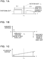
- FIGs. 1A - 1C are diagrams illustrating influences of wavelength dispersion and frequency-dependent polarization rotation when wavelength conversion is applied to WDM.
- FIG. 1A illustrates spectra of input signal light and converted signal light
- FIG. 1B is a diagram illustrating phase mismatch between input signal light and converted signal light
- FIG. 1C illustrates mismatch in polarization rotation amount between input signal light and converted signal light.
- Making input signal light and excitation light having a wavelength of vp incident on a nonlinear optical medium allows a converted signal light having a central wavelength of (2v P - vi) to be obtained as output light of the nonlinear optical medium owing to the nonlinear optical effect.
- a light wave having a sufficient intensity is incident on a nonlinear optical medium, nonlinear (second-order or more) polarization occurs inside the nonlinear optical medium on the incident electric field, and a light wave having a frequency component different from that of the incident light is generated by the oscillation of the polarization.
- wavelength conversion characteristics over a wide band are desired.
- the difference in wavelength dispersion amount between input signal light and converted signal light is significant at an end of the waveband away from the excitation light wavelength v P , so that the spectrum of the converted signal light is degraded by the phase mismatch.
- the degradation of the spectrum lowers the conversion efficiency and suppresses the conversion operation over a wide band.
- frequency-dependent polarization rotation occurs in light propagating inside a nonlinear optical medium due to the birefringence of the nonlinear optical medium.
- the conversion efficiency is lowered due to the mismatch in polarization between the input signal light and the converted signal light.
- the conversion efficiency is lowered due to the polarization crosstalk between the two beams of excitation light.
- the embodiment uses nonlinear optical media with at least one of phase mismatch due to wavelength dispersion and frequency-dependent polarization rotation being reduced. Specifically, nonlinear optical media having different signs or having different properties are combined to compensate for at least one of wavelength dispersion and frequency-dependent polarization rotation at the time of wavelength conversion.
- combination of properties having different signs include a combination of a nonlinear optical medium whose polarization rotates clockwise and a nonlinear optical medium whose polarization rotates counterclockwise depending on a wavelength in the Stokes space, a combination of a nonlinear optical medium having a positive fourth-order dispersion value and a nonlinear optical medium having a negative fourth-order dispersion value, a combination of a nonlinear optical medium having a positive third-order dispersion value and a nonlinear optical medium having a negative third-order dispersion value, and the like. Two or more combinations among these combinations may be combined. For example, a combination of nonlinear optical media having clockwise and counterclockwise polarization rotations and a combination of nonlinear optical media having a positive fourth-order dispersion value and a negative fourth-order dispersion value may be combined.
- nonlinear optical media having different properties or having properties with different signs are arranged alternately in an optical axis direction. At least one of wavelength dispersion and frequency-dependent polarization rotation is compensated for to reduce at least one of phase mismatch and polarization mismatch between frequency components. This makes it possible to achieve wavelength conversion over a wide band.
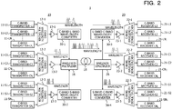
- FIG. 2 is a schematic diagram of a transmission system 1 according to the embodiment.
- the transmission system 1 includes an optical communication device 10 on the transmission side, an optical communication device 20 on the reception side, and an optical transmission path 18 coupling these optical communication devices 10 and 20.
- the optical communication device 10 and the optical communication device 20 each have both functions on the transmission side and the reception side.
- the function on the transmission side of the optical communication device 10 and the function on the reception side of the optical communication device 20 are described by way of example.
- the optical communication device 10 includes optical transmitters 11-L1 to 11-LN L included in a first group, optical transmitters 11-C1 to 11-CN C included in a second group, and optical transmitters 11-S1 to 11-SN S included in a third group (hereinafter referred to collectively as "optical transmitters 11" as appropriate).
- These optical transmitters 11 are each a photoelectric conversion front end circuit of an optical transponder, for example.
- the optical transmitters 11 have the same configuration and output signals having a wavelength channel of the C band (1530 to 1565 nm) (which are referred to as "C-band transmitter” in the drawings).
- Output light of the optical transmitters 11-L1 to 11-LN L in the first group is multiplexed by a first wavelength multiplexer 12-1.
- Output light of the optical transmitters 11-C1 to 11-CN C in the second group is multiplexed by a second wavelength multiplexer 12-2.
- Output light of the optical transmitters 11-S1 to 11-SN S in the third group is multiplexed by a third wavelength multiplexer 12-3.
- the first wavelength multiplexer 12-1 to the third wavelength multiplexer 12-3 have the same function and configuration and multiplex inputted signals of multiple wavelength channels and output resultant signals.
- Output of the first wavelength multiplexer 12-1 is amplified by a first optical amplifier 13-1.
- Output of the second wavelength multiplexer 12-2 is amplified by a second optical amplifier 13-2.
- Output of the third wavelength multiplexer 12-3 is amplified by a third optical amplifier 13-3.
- the first optical amplifier 13-1 to the third optical amplifier 13-3 have the same function and configuration and amplify multiplexed optical signals of the C-band.
- the C-band signal light amplified by the first optical amplifier 13-1 is subjected to wavelength conversion by a first wavelength converter 30-1 and inputted to a wavelength multiplexer 16.
- the C-band signals are converted to L-band signals all together.
- the C-band signal light amplified by the third optical amplifier 13-3 is subjected to wavelength conversion by a second wavelength converter 30-2 and inputted to the wavelength multiplexer 16.
- the C-band signals are converted to S-band signals all together.
- the C-band signal light amplified by the second optical amplifier 13-2 is not subjected to wavelength conversion and is inputted to the wavelength multiplexer 16 as it is.
- the wavelength multiplexer 16 multiplexes the L-band signal light, the C-band signal light, and the S-band signal light and outputs the resultant optical signal to the optical transmission path 18.
- This optical signal contains wavelength channels from the L-band to the S-band and optical communication over a wide band is carried out.
- the optical signal is propagated through the optical transmission path 18 and is received by the optical communication device 20.
- the optical signal received by the optical communication device 20 is demultiplexed into L-band signal light, C-band signal light, and S-band signal light by a wavelength demultiplexer 26.
- the L-band signal light is converted to C-band signal light by a third wavelength converter 30-3, is amplified by an optical amplifier 23-1, and is demultiplexed into different wavelength channels by a first wavelength demultiplexer 22-1.
- the S-band signal light is converted to C-band signal light by a fourth wavelength converter 30-4, is amplified by an optical amplifier 23-3, and is demultiplexed into different wavelength channels by a third wavelength demultiplexer 22-3.
- the C-band signal light is not subjected to wavelength conversion, is amplified by an optical amplifier 23-2 as it is, and is demultiplexed into different wavelength channels by a second wavelength demultiplexer 22-2.
- the optical amplifiers 23-1 to 23-3 have the same function and configuration.
- the wavelength demultiplexers 22-1 to 22-3 have the same function and configuration and demultiplex C-band signal light into different wavelength channels, respectively.
- the beams of signal light demultiplexed by the first wavelength demultiplexer 22-1 are supplied to optical receivers 21-L1 to 21-LN L in a first group.
- the beams of signal light demultiplexed by the second wavelength demultiplexer 22-2 are supplied to optical receivers 21-C1 to 21-CN C in a second group.
- the beams of signal light demultiplexed by the third wavelength demultiplexer 22-3 are supplied to optical receivers 21-S1 to 21-SN S in a third group.
- the optical receivers 21-L1 to 21-LN L , the optical receivers 21-C1 to 21-CN C , and the optical receivers 21-S1 to 21-SN S are referred to collectively as "optical receivers 21" as appropriate.
- optical receivers 21 are each a photoelectric conversion front end circuit of an optical transponder, for example.
- the optical receivers 21 have the same configuration and convert light having a wavelength channel of the C band (1530 to 1565 nm) to electric signals (which are referred to as "C-band receiver” in the drawings).
- This transmission system does not use optical components for individual bands but uses common optical transmitters and receivers, wavelength multiplexers and demultiplexers, optical amplifiers, and the like.
- Using the wavelength converters 30-1 to 30-4 makes it possible to expand optical communication bands using the existing optical components.
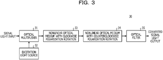
- FIG. 3 is a schematic diagram of a wavelength converter used as the wavelength converters 30 of the embodiment.
- Each wavelength converter 30 includes an optical multiplexer 31, an excitation light source 32, a first nonlinear optical medium 33, a second nonlinear optical medium 34, and an optical filter 35.
- the first nonlinear optical medium 33 and the second nonlinear optical medium 34 have properties different from each other, for example different signs.
- Signal light having a central wavelength of vi is inputted to the optical multiplexer 31.
- the signal light to be inputted contains light having multiple wavelength channels, and the light having multiple wavelength channels is converted to different wavelength bands all together.
- Excitation light having a wavelength different from that of the inputted signal light is inputted from the excitation light source 32 to the optical multiplexer 31.
- the excitation light and the signal light are multiplexed and inputted to the first nonlinear optical medium 33.
- the phase of light having each wavelength channel contained in the signal light and the phase of the excitation light are assumed to match each other on the incidence plane of the first nonlinear optical medium 33.
- the first nonlinear optical medium 33 is for example a nonlinear optical medium with clockwise polarization rotation. Converted signal light newly generated by the nonlinear optical effect is propagated in the first nonlinear optical medium 33 while receiving clockwise polarization rotation.
- the input signal light, the excitation light, and the converted signal light after being propagated a predetermined distance in the first nonlinear optical medium 33, are incident on the second nonlinear optical medium 34.
- the second nonlinear optical medium 34 is for example a nonlinear optical medium with counterclockwise polarization rotation.
- the input signal light, the excitation light, and the converted signal light are propagated in the second nonlinear optical medium 34 while receiving counterclockwise polarization rotation.
- the output light of the second nonlinear optical medium 34 is incident on the optical filter 35.
- the input signal light and the excitation light are removed and only the converted signal light is outputted.
- FIG. 4 is a schematic diagram for explaining the effect of the wavelength converter 30 of FIG. 3 .
- the horizontal axis indicates the propagation position in the nonlinear optical medium, that is, the distance from the incidence plane of the first nonlinear optical medium 33, for example. It is assumed that the first nonlinear optical medium 33 and the second nonlinear optical medium 34 continue in the optical axis direction and the influence of the interface therebetween may be ignored.
- the vertical axis indicates the relative polarization angle between the excitation light and the input signal light.
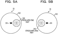
- FIGs. 5A and 5B illustrate configuration examples of the nonlinear optical medium 33 and the nonlinear optical medium 34.
- the first nonlinear optical medium 33 is an optical fiber of stress applying type, and is provided with a stress-applying part 333 at a certain position in a circumferential direction of a cladding 332 surrounding a core 331 in a cross section orthogonal to the optical axis.
- the stress-applying part 333 applies stress to part of the circumference of the core 331. Since the polarization rotation is affected by the circularity of a core, the application of stress to a certain side of the circumference of the core 331 lowers the circularity of the cross-sectional shape of the core to generate the polarization rotation.
- FIG. 5B is a cross-sectional view of the second nonlinear optical medium 34 as viewed from the same side as that in FIG. 5A .
- the second nonlinear optical medium 34 includes a stress-applying part 343 at a certain position in the circumferential direction of a cladding 342 surrounding a core 341 in a cross section orthogonal to the optical axis.
- the stress-applying part 343 is located at the opposite side of the core 341 from the stress-applying part 333 of the first nonlinear optical medium 33. Deflecting part of the circumference of the core 341 at a position on the opposite side from the deflection of the core 331 of the first nonlinear optical medium 33 causes the polarization rotation in an opposite direction from the first nonlinear optical medium 33.
- the configurations of the first nonlinear optical medium 33 and the second nonlinear optical medium 34 are not limited to those illustrated in FIGs. 5A and 5B .
- the first nonlinear optical medium 33 and the second nonlinear optical medium 34 may be achieved by processing the surface shape of the core of an elliptical-core polarization maintaining fiber.
- the first nonlinear optical medium 33 is made by making slightly smaller the radius of curvature of the ellipse of the elliptical core near one of the vertices along the major axis or the minor axis of the ellipse.
- the second nonlinear optical medium 34 is made by changing, near the second vertex at a position symmetrical to the first vertex with respect to the origin of the elliptical cross section of the core, the shape of the elliptical face like the first vertex. Changing the shape of the core surface at a position at the opposite side of the origin on the circumference of the ellipse in the same manner makes it possible to generate the clockwise polarization rotation and the counterclockwise polarization rotation.
- FIGs. 6A - 6C are concept diagrams illustrating the effect of the embodiment in various wavelength conversion methods.
- FIG. 6A illustrates suppression of spectrum degradation of converted signal light in the wavelength conversion with a single wavelength of excitation light.
- FIG. 6B illustrates suppression of spectrum degradation of converted signal light in the wavelength conversion with orthogonally polarized two wavelengths of excitation light.
- FIG. 6C illustrates suppression of spectrum degradation of converted signal light in the wavelength conversion with parallel polarized two wavelengths of excitation light.
- the solid lines indicate spectra obtained in the embodiment, and dashed lines indicate spectra of converted signal light in the case of not employing the wavelength conversion configuration of the embodiment.
- excitation light having the same polarization direction as that of the incident signal light is made incident.
- Combining the first nonlinear optical medium 33 and the second nonlinear optical medium 34, which have different properties from each other, makes it possible to suppress spectrum degradation in end regions of converted signal light separated from the excitation light by ⁇ v.
- first excitation light v P1 having a frequency higher than that of the target converted signal light and second excitation light v P2 having a frequency lower than that of the input signal light are made incident on a nonlinear optical medium.
- the polarization directions of the first excitation light v P1 and the second excitation light v P2 are orthogonal to each other.
- the polarization direction of the input signal light is the same as the polarization direction of the first excitation light v P1 and is orthogonal to the polarization direction of the second excitation light v P2 .
- the polarization direction of the generated converted signal light is orthogonal to the polarization direction of the input signal light and is also orthogonal to the polarization direction of the first excitation light v P1 .
- the spectrum of the converted signal light is degraded in an end region closer to the zero dispersion wavelength v 0 .
- combining the first nonlinear optical medium 33 and the second nonlinear optical medium 34 having opposite properties to compensate for wavelength dispersion or frequency-dependent polarization rotation as in the embodiment makes it possible to maintain the conversion efficiency over a wide band.
- first excitation light v P1 near the central wavelength of the target converted signal light and second excitation light v P2 near the central wavelength of the input signal light are made incident on a nonlinear optical medium.
- the polarization directions of the first excitation light v P1 and the second excitation light v P2 are the same.
- the polarization direction of the incident signal light and the polarization direction of the second excitation light v P2 are orthogonal to each other.
- the polarization direction of the generated converted signal light is the same as the polarization direction of the input signal light and is orthogonal to the polarization direction of the first excitation light v P1 .
- the spectrum of the converted signal light is degraded in both of a spectrum end closer to the zero dispersion wavelength v 0 and a spectrum end away from the zero dispersion wavelength v 0 .
- combining the first nonlinear optical medium 33 and the second nonlinear optical medium 34 having opposite properties to compensate for wavelength dispersion or frequency-dependent polarization rotation as in the embodiment makes it possible to maintain the conversion efficiency over a wide band.
- FIG. 7 is a diagram for explaining the compensation for a decrease in efficiency due to the polarization rotation with the wavelength conversion using a single wavelength of excitation light. It is desirable that the polarization direction of the input signal light is the same as the polarization direction of the excitation light v P .
- the polarization plane of light propagating in a nonlinear optical medium rotates depending on the frequency. The rotation angle from the polarization direction of excitation light at this time is ⁇ (v).
- the frequency-dependent polarization rotation is defined by Formula (1) as a function of a differential group delay (DGD) between polarizations and a polarization state depolarization (PSD).
- DGD differential group delay
- PSD polarization state depolarization
- the efficiency ratio ⁇ depending on the presence or absence of polarization rotation generated in the longitudinal direction or the optical axis direction of a nonlinear optical medium having a length of L is a ratio of the value of integral of the conversion efficiency ⁇ R per unit length "l" when there is polarization rotation to the value of integral of the conversion efficiency ⁇ NR per unit length "l" when there is no polarization rotation and is expressed by Formula (2).
- ⁇ ⁇ ⁇ 0 L ⁇ R l dl 2 ⁇ 0 L ⁇ NR dl 2
- the wavelength converter is designed such that PSD/DGD becomes smaller than 0.56 ps, for example.
- Formula (2) is expanded to Formula (8).
- ⁇ ⁇ ⁇ 0 L 1 ⁇ R 1 l dl + ⁇ 0 L 2 ⁇ NR 2 dl ⁇ 0 L 1 ⁇ NR 1 dl + ⁇ 0 L 2 ⁇ NR 2 dl 2
- L1 is the length of the nonlinear optical medium 33 with clockwise frequency-dependent polarization rotation
- L2 is the length of the nonlinear optical medium 34 with counterclockwise frequency-dependent polarization rotation.
- Formula (10) is obtained.
- FIG. 8A is a diagram for explaining compensation for polarization crosstalk when using orthogonally polarized two wavelengths of excitation light
- FIG. 8B is a diagram for explaining compensation for polarization crosstalk when using parallel polarized two wavelengths of excitation light.
- polarization crosstalk is generated by polarization rotation between the two beams of excitation light, so that noise is contained in converted signal light, degrading the signal quality.
- the crosstalk XT of Formula (12) is represented by a ratio between the "integral of the component efficiency ⁇ ROrth per unit length generated by interaction between orthogonal polarization components generated by the rotation” and the "integral of the component efficiency ⁇ RPara per unit length generated by interaction between parallel polarization components that do not rotate".
- the orthogonal polarization components and the parallel polarization components mentioned herein refer to components orthogonal to the polarization of incident light and components parallel to the polarization of incident light.
- the condition for performing wavelength conversion at a efficiency ratio of ⁇ > 0.5 over a band of 5 THz is different depending on the arrangement of two beams of excitation light.
- the condition of Formula (17) is obtained.
- the wavelength converter has to be designed to satisfy PSD/DGD ⁇ 0.08 ps.
- the wavelength converter has to be designed to satisfy PSD/DGD ⁇ 0.04 ps.
- Formula (12) is expanded to Formula (19).
- ⁇ ⁇ ⁇ 0 L 1 ⁇ ROrth 1 l dl + ⁇ 0 L 2 ⁇ ROrth 2 l dl ⁇ 0 L 1 ⁇ RPara 1 l dl + ⁇ 0 L 2 ⁇ RPara 2 l dl 2
- L1 is the length of the nonlinear optical medium 33 with clockwise frequency-dependent polarization rotation
- L2 is the length of the nonlinear optical medium 34 with counterclockwise frequency-dependent polarization rotation.
- ⁇ ⁇ + d ⁇ dv v ⁇ v 0 + 1 2 d 2 ⁇ dv 2 v ⁇ v 0 2 + 1 6 d 3 ⁇ dv 3 v ⁇ v 0 3 + 1 24 d 4 ⁇ dv 4 v ⁇ v 0 4
- v 0 is a zero-dispersion frequency (second-order dispersion is zero) of a nonlinear optical media.
- the wavelength converter has to be designed to satisfy formula (33).
- d 3 ⁇ dv 3 ⁇ 1.78 ⁇ 10 ⁇ 39 s 3 / m 1.78 ps 3 / km
- Formula (24) is expanded to Formula (34).
- ⁇ ⁇ sin ⁇ ⁇ 1 L 1 / 2 + sin ⁇ ⁇ 1 L 1 / 2 + ⁇ ⁇ 2 L 2 / 2 ⁇ sin ⁇ ⁇ 1 L 1 / 2 ⁇ ⁇ 1 L 1 / 2 + ⁇ ⁇ 2 L 1 + L 2 / 2 ⁇ ⁇ ⁇ 2 L 1 / 2 2
- ⁇ p is a function of only the fourth-order dispersion in the case of wavelength dispersion with a single wavelength of excitation light and orthogonally polarized two wavelengths of excitation light, and is a function of only the third-order dispersion in the case of wavelength dispersion with parallel polarized two wavelengths of excitation light.
- Formula (35) is compared with Formula (24)
- combining nonlinear optical media having a positive dispersion value and a negative dispersion value as in the embodiment makes it possible to relieve the demand as compared with the case of using a single nonlinear optical medium. Specifically, it is possible to suppress a decrease in efficiency due to the crosstalk to the same level even when the fourth-order dispersion or the third-order dispersion per unit length is twice those of Formula (29) or Formula (32), for example.
- FIG. 9 is a schematic diagram of a wavelength converter 30A.
- the wavelength converter 30A is applied to wavelength conversion using a single wavelength of excitation light and orthogonally polarized two wavelengths of excitation light, and compensates for spectrum degradation due to fourth-order dispersion as described above.
- the wavelength converter 30A includes an optical multiplexer 31, an excitation light source 32, a first nonlinear optical medium 133 having a positive fourth-order dispersion value, a second nonlinear optical medium 134 having a negative fourth-order dispersion value, and an optical filter 35.
- the length of the first nonlinear optical medium 133 and the length of the second nonlinear optical medium 134 in the optical axis direction are designed such that the relative differential group delay or the phase mismatch between incident light and converted signal light becomes minimum at the exit plane of the second nonlinear optical medium.
- the order of arrangement of the nonlinear optical medium 133 having a positive fourth-order dispersion value and the nonlinear optical medium 134 having a negative fourth-order dispersion value may be reversed.
- Two sets or more of nonlinear optical media may be used and arranged such that positive and negative fourth-order dispersion values are arranged alternately.
- This wavelength converter 30A allows fourth-order dispersion having a size twice that of the case of using a single nonlinear optical medium at the same efficiency ratio (or a decrease in efficiency).
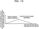
- FIG. 10 is a diagram for explaining the effect of the wavelength converter 30A of FIG. 9 .
- the horizontal axis indicates the propagation position in the nonlinear optical medium, that is, the distance from the incidence plane of the first nonlinear optical medium 133, for example. It is assumed that the first nonlinear optical medium 133 and the second nonlinear optical medium 134 continue in the optical axis direction and the influence of the interface therebetween may be ignored.
- the vertical axis indicates the relative differential group delay between input signal light and converted signal light.
- the relative differential group delay increases upon the influence of fourth-order dispersion, and phase deviation between the input signal light and the converted signal light increases.
- propagation in the second nonlinear optical medium 134 having a fourth-order dispersion value of the opposite sign reduces the relative differential group delay, so that the relative differential group delay becomes minimum at the output plane of the second nonlinear optical medium 134.
- FIG. 11 is a schematic diagram of a wavelength converter 30B.
- the wavelength converter 30B is applied to wavelength conversion using parallel polarized two wavelengths of excitation light, and compensates for spectrum degradation due to third-order dispersion as described above.
- the wavelength converter 30B includes an optical multiplexer 31, an excitation light source 32, a first nonlinear optical medium 233 having a positive third-order dispersion value, a second nonlinear optical medium 234 having a negative third-order dispersion value, and an optical filter 35.
- the length of the first nonlinear optical medium 233 and the length of the second nonlinear optical medium 234 in the optical axis direction are designed such that the relative differential group delay or the phase mismatch between incident light and converted signal light becomes minimum at the exit plane of the second nonlinear optical medium.
- the order of arrangement of the nonlinear optical medium 233 having a positive third-order dispersion value and the nonlinear optical medium 234 having a negative third-order dispersion value may be reversed.
- Two sets or more of nonlinear optical media may be used and arranged such that positive and negative third-order dispersion values are arranged alternately.
- This wavelength converter 30B allows third-order dispersion having a size twice that of the case of using a single nonlinear optical medium at the same efficiency ratio (or a decrease in efficiency).
- FIG. 12 is a diagram for explaining the effect of the wavelength converter 30B of FIG. 11 .
- the horizontal axis indicates the propagation position in the nonlinear optical medium, that is, the distance from the incidence plane of the first nonlinear optical medium 233, for example. It is assumed that the first nonlinear optical medium 233 and the second nonlinear optical medium 234 continue in the optical axis direction and the influence of the interface therebetween may be ignored.
- the vertical axis indicates the relative differential group delay between input signal light and converted signal light.
- the relative differential group delay increases upon the influence of third-order dispersion, and phase deviation between the input signal light and the converted signal light increases.
- propagation in the second nonlinear optical medium 234 having a third-order dispersion value of the opposite sign reduces the relative differential group delay, so that the relative differential group delay becomes minimum at the output plane of the second nonlinear optical medium 234.
- All of the wavelength converters 30, 30A, and 30B may be applied to the optical communication devices 10 and 20 in FIG. 2 .
- Controlling the wavelength vp of excitation light makes it possible to convert input signal light to a desired wavelength band (the L band, the S band, or the like).
- a desired wavelength band the L band, the S band, or the like.
- combining the nonlinear optical media having different signs or properties makes it possible to compensate for at least one of the phase mismatch due to dispersion properties and frequency-dependent polarization rotation due to birefringence properties, and thus to maintain the wavelength conversion efficiency over a wide band.
- the wavelength conversion of the embodiment encompasses overall optical parametric amplifications including generation of sum frequency or difference frequency, generation of harmonic, optical parametric oscillation, and the like.
- a "wavelength converter” when mentioned in claims, it encompasses a sum frequency generator, a difference frequency generator, a harmonic generator, optical parametric oscillator, optical parametric amplifier, and the like.
- a first nonlinear optical medium and a second nonlinear optical medium having different optical properties (or different signs) from each other are combined.
- Excitation light having a first wavelength, excitation light having a second wavelength, and signal light having a third wavelength are made incident on a first nonlinear optical medium to generate idler light having a fourth wavelength.
- the length (L1) of the first nonlinear optical medium and the length (L2) of the second nonlinear optical medium in the optical axis direction are designed such that at least one of the relative differential group delay (or the phase mismatch) of the converted signal light relative to the input signal light and the relative polarization angle between the input signal light and the excitation light is minimized at the exit plane of the second nonlinear optical medium.
- the wavelength conversion or optical parametric amplification using a single wavelength of excitation light may be considered as the case where the first excitation light and the second excitation light have the same wavelength or frequency in a four-wave mixing.
- the excitation light source may be a light source outside the wavelength converter or optical parametric amplifier. Excitation light may be made incident on the first nonlinear optical medium through an optical waveguide such as an optical fiber, for example.
Landscapes
- Physics & Mathematics (AREA)
- Nonlinear Science (AREA)
- General Physics & Mathematics (AREA)
- Optics & Photonics (AREA)
- Engineering & Computer Science (AREA)
- Computer Networks & Wireless Communication (AREA)
- Signal Processing (AREA)
- Electromagnetism (AREA)
- Chemical & Material Sciences (AREA)
- Dispersion Chemistry (AREA)
- Optical Modulation, Optical Deflection, Nonlinear Optics, Optical Demodulation, Optical Logic Elements (AREA)
- Optical Communication System (AREA)
Abstract
Description
- The embodiments discussed herein are related to an optical communication device, an optical transmission system, a wavelength converter, and an optical communication method.
- With an increase in communication demand, an expansion in transmission capacity has been desirable. The transmission capacity is expanded by, for example, increasing the number of cores of optical fibers, increasing the capacity of optical signals per wavelength, and increasing the number of wavelength division multiplexing (WDM) channels. Since the cost of laying optical fibers is high, it is desirable to expand the transmission capacity without increasing the number of optical fiber cores. It is desirable that a transmission device has a transmission capacity increased by increasing the optical signal capacity and the number of WDM channels. However, there is a limitation on an expansion in transmission capacity with only the communication band (C band). To further expand the transmission capacity, it is desirable to utilize not only the C band but also the long wavelength region (L band) and the short wavelength region (S band) of the C band.
- Developing optical transmitters and receivers, wavelength multiplexers and demultiplexers, optical amplifiers, and other components for the S band, the C band, and the L band increases the costs as compared with a transmission device using a single one wavelength band. It has been studied to expand the communication band utilizing wavelength conversions with a C-band transmission device.
- A nonlinear optical fiber has been proposed that has fourth-order dispersion in a predetermined range in a wavelength range of 1520 nm to 1620 nm. Wavelength conversions with a single wavelength of excitation light using a four-wave mixing and wavelength conversions using orthogonally polarized two wavelengths of excitation light and parallel polarized two wavelengths of excitation light have been known.
- Related art disclosed includes, for example, Japanese Laid-open Patent Publication No.
2007-17907 - In the wavelength conversions, the phase mismatch between the input light and the converted signal light due to the wavelength dispersion and the polarization mismatch due to the frequency-dependent polarization rotation cause the conversion efficiency to decrease. To conduct wavelength conversion on WDM signals all together, wavelength conversion is desirable that has favorable wavelength conversion characteristics in a wide band.
- An object of the present disclosure is to expand the communication capacity by achieving wavelength conversion characteristics over a wide band in optical communications.
- According to an aspect of the embodiments, an optical communication device includes an excitation light source that outputs excitation light, a multiplexer that multiplexes signal light and the excitation light outputted from the excitation light source, a first nonlinear optical medium into which the multiplexed excitation light and the signal light are inputted, and a second nonlinear optical medium that is coupled to the first nonlinear optical medium in series and has an optical property different from that of the first nonlinear optical medium.
- It is made possible to expand the communication capacity by achieving wavelength conversion characteristics over a wide band in optical communications.
-
-
FIGs. 1A - 1C are diagrams for explaining a decrease in conversion efficiency when wavelength conversion is applied to WDM; -
FIG. 2 is a schematic diagram of an optical transmission system to which an embodiment is applied; -
FIG. 3 is a schematic diagram of a wavelength converter of the embodiment; -
FIG. 4 is a schematic diagram for explaining the effect of the wavelength converter of the embodiment; -
FIGs. 5A and 5B are diagrams illustrate examples of nonlinear optical media used in a wavelength converter; -
FIGs. 6A - 6C are concept diagrams illustrating the effect of the embodiment in various wavelength conversion methods; -
FIG. 7 is a diagram for explaining the compensation for polarization rotation with wavelength conversion using a single wavelength of excitation light; -
FIGs. 8A and 8B is a diagram for explaining compensation for polarization crosstalk with wavelength conversion using orthogonally polarized two wavelengths of excitation light and parallel polarized two wavelengths of excitation light; -
FIG. 9 is a diagram illustrating a modification of the wavelength converter of the embodiment; -
FIG. 10 is a schematic diagram for explaining the effect of the wavelength converter ofFIG. 9 ; -
FIG. 11 is a diagram illustrating another modification of the wavelength converter of the embodiment; and -
FIG. 12 is a schematic diagram for explaining the effect of the wavelength converter ofFIG. 11 . -
FIGs. 1A - 1C are diagrams illustrating influences of wavelength dispersion and frequency-dependent polarization rotation when wavelength conversion is applied to WDM.FIG. 1A illustrates spectra of input signal light and converted signal light,FIG. 1B is a diagram illustrating phase mismatch between input signal light and converted signal light, andFIG. 1C illustrates mismatch in polarization rotation amount between input signal light and converted signal light. - Making input signal light and excitation light having a wavelength of vp incident on a nonlinear optical medium allows a converted signal light having a central wavelength of (2vP - vi) to be obtained as output light of the nonlinear optical medium owing to the nonlinear optical effect. When a light wave having a sufficient intensity is incident on a nonlinear optical medium, nonlinear (second-order or more) polarization occurs inside the nonlinear optical medium on the incident electric field, and a light wave having a frequency component different from that of the incident light is generated by the oscillation of the polarization.
- In the case of applying wavelength conversion to WDM, since light containing a plurality of wavelength components is converted all together, wavelength conversion characteristics over a wide band are desired.
- Making the wavelength vP of excitation light coincident with zero dispersion wavelength v0 makes it possible to maintain a high intensity of converted signal light. In wavelength conversion over a wide band, the spectrum of converted signal light is distorted by wavelength dispersion and frequency-dependent polarization rotation, lowering the conversion efficiency.
- As in
FIGs. 1A - 1C , in the case of a single wavelength of excitation light, the difference in wavelength dispersion amount between input signal light and converted signal light is significant at an end of the waveband away from the excitation light wavelength vP, so that the spectrum of the converted signal light is degraded by the phase mismatch. The degradation of the spectrum lowers the conversion efficiency and suppresses the conversion operation over a wide band. To provide a sufficient intensity to a converted signal light generated inside a nonlinear optical medium and perform conversion operation over a wide band, it is desirable that the phases of the input signal light and the converted signal light match over a desired band. - As illustrated in
FIG. 1C , frequency-dependent polarization rotation occurs in light propagating inside a nonlinear optical medium due to the birefringence of the nonlinear optical medium. In this case, the conversion efficiency is lowered due to the mismatch in polarization between the input signal light and the converted signal light. In the case of using two beams of excitation light, the conversion efficiency is lowered due to the polarization crosstalk between the two beams of excitation light. - If it is possible to maintain the phase match between input signal light and converted signal light over a predetermined wavelength band and reduce the polarization rotation, a wavelength conversion over a wide band with a high efficiency is achieved.
- The embodiment uses nonlinear optical media with at least one of phase mismatch due to wavelength dispersion and frequency-dependent polarization rotation being reduced. Specifically, nonlinear optical media having different signs or having different properties are combined to compensate for at least one of wavelength dispersion and frequency-dependent polarization rotation at the time of wavelength conversion.
- Examples of combination of properties having different signs include a combination of a nonlinear optical medium whose polarization rotates clockwise and a nonlinear optical medium whose polarization rotates counterclockwise depending on a wavelength in the Stokes space, a combination of a nonlinear optical medium having a positive fourth-order dispersion value and a nonlinear optical medium having a negative fourth-order dispersion value, a combination of a nonlinear optical medium having a positive third-order dispersion value and a nonlinear optical medium having a negative third-order dispersion value, and the like. Two or more combinations among these combinations may be combined. For example, a combination of nonlinear optical media having clockwise and counterclockwise polarization rotations and a combination of nonlinear optical media having a positive fourth-order dispersion value and a negative fourth-order dispersion value may be combined.
- In a favorable configuration, nonlinear optical media having different properties or having properties with different signs are arranged alternately in an optical axis direction. At least one of wavelength dispersion and frequency-dependent polarization rotation is compensated for to reduce at least one of phase mismatch and polarization mismatch between frequency components. This makes it possible to achieve wavelength conversion over a wide band.
-
FIG. 2 is a schematic diagram of atransmission system 1 according to the embodiment. Thetransmission system 1 includes anoptical communication device 10 on the transmission side, anoptical communication device 20 on the reception side, and anoptical transmission path 18 coupling theseoptical communication devices optical communication device 10 and theoptical communication device 20 each have both functions on the transmission side and the reception side. For the sake of explanation, the function on the transmission side of theoptical communication device 10 and the function on the reception side of theoptical communication device 20 are described by way of example. - The
optical communication device 10 includes optical transmitters 11-L1 to 11-LNL included in a first group, optical transmitters 11-C1 to 11-CNC included in a second group, and optical transmitters 11-S1 to 11-SNS included in a third group (hereinafter referred to collectively as "optical transmitters 11" as appropriate). Theseoptical transmitters 11 are each a photoelectric conversion front end circuit of an optical transponder, for example. Theoptical transmitters 11 have the same configuration and output signals having a wavelength channel of the C band (1530 to 1565 nm) (which are referred to as "C-band transmitter" in the drawings). - Output light of the optical transmitters 11-L1 to 11-LNL in the first group is multiplexed by a first wavelength multiplexer 12-1. Output light of the optical transmitters 11-C1 to 11-CNC in the second group is multiplexed by a second wavelength multiplexer 12-2. Output light of the optical transmitters 11-S1 to 11-SNS in the third group is multiplexed by a third wavelength multiplexer 12-3. The first wavelength multiplexer 12-1 to the third wavelength multiplexer 12-3 have the same function and configuration and multiplex inputted signals of multiple wavelength channels and output resultant signals.
- Output of the first wavelength multiplexer 12-1 is amplified by a first optical amplifier 13-1. Output of the second wavelength multiplexer 12-2 is amplified by a second optical amplifier 13-2. Output of the third wavelength multiplexer 12-3 is amplified by a third optical amplifier 13-3. The first optical amplifier 13-1 to the third optical amplifier 13-3 have the same function and configuration and amplify multiplexed optical signals of the C-band.
- The C-band signal light amplified by the first optical amplifier 13-1 is subjected to wavelength conversion by a first wavelength converter 30-1 and inputted to a
wavelength multiplexer 16. In this example, the C-band signals are converted to L-band signals all together. - The C-band signal light amplified by the third optical amplifier 13-3 is subjected to wavelength conversion by a second wavelength converter 30-2 and inputted to the
wavelength multiplexer 16. In this example, the C-band signals are converted to S-band signals all together. - The C-band signal light amplified by the second optical amplifier 13-2 is not subjected to wavelength conversion and is inputted to the
wavelength multiplexer 16 as it is. - The
wavelength multiplexer 16 multiplexes the L-band signal light, the C-band signal light, and the S-band signal light and outputs the resultant optical signal to theoptical transmission path 18. This optical signal contains wavelength channels from the L-band to the S-band and optical communication over a wide band is carried out. The optical signal is propagated through theoptical transmission path 18 and is received by theoptical communication device 20. - The optical signal received by the
optical communication device 20 is demultiplexed into L-band signal light, C-band signal light, and S-band signal light by awavelength demultiplexer 26. The L-band signal light is converted to C-band signal light by a third wavelength converter 30-3, is amplified by an optical amplifier 23-1, and is demultiplexed into different wavelength channels by a first wavelength demultiplexer 22-1. - The S-band signal light is converted to C-band signal light by a fourth wavelength converter 30-4, is amplified by an optical amplifier 23-3, and is demultiplexed into different wavelength channels by a third wavelength demultiplexer 22-3. The C-band signal light is not subjected to wavelength conversion, is amplified by an optical amplifier 23-2 as it is, and is demultiplexed into different wavelength channels by a second wavelength demultiplexer 22-2.
- The optical amplifiers 23-1 to 23-3 have the same function and configuration. The wavelength demultiplexers 22-1 to 22-3 have the same function and configuration and demultiplex C-band signal light into different wavelength channels, respectively.
- The beams of signal light demultiplexed by the first wavelength demultiplexer 22-1 are supplied to optical receivers 21-L1 to 21-LNL in a first group. The beams of signal light demultiplexed by the second wavelength demultiplexer 22-2 are supplied to optical receivers 21-C1 to 21-CNC in a second group. The beams of signal light demultiplexed by the third wavelength demultiplexer 22-3 are supplied to optical receivers 21-S1 to 21-SNS in a third group. The optical receivers 21-L1 to 21-LNL, the optical receivers 21-C1 to 21-CNC, and the optical receivers 21-S1 to 21-SNS are referred to collectively as "
optical receivers 21" as appropriate. - These
optical receivers 21 are each a photoelectric conversion front end circuit of an optical transponder, for example. Theoptical receivers 21 have the same configuration and convert light having a wavelength channel of the C band (1530 to 1565 nm) to electric signals (which are referred to as "C-band receiver" in the drawings). - This transmission system does not use optical components for individual bands but uses common optical transmitters and receivers, wavelength multiplexers and demultiplexers, optical amplifiers, and the like. Using the wavelength converters 30-1 to 30-4 makes it possible to expand optical communication bands using the existing optical components.
-
FIG. 3 is a schematic diagram of a wavelength converter used as thewavelength converters 30 of the embodiment. Eachwavelength converter 30 includes anoptical multiplexer 31, anexcitation light source 32, a first nonlinearoptical medium 33, a second nonlinearoptical medium 34, and anoptical filter 35. The first nonlinearoptical medium 33 and the second nonlinear optical medium 34 have properties different from each other, for example different signs. - Signal light having a central wavelength of vi is inputted to the
optical multiplexer 31. The signal light to be inputted contains light having multiple wavelength channels, and the light having multiple wavelength channels is converted to different wavelength bands all together. Excitation light having a wavelength different from that of the inputted signal light is inputted from theexcitation light source 32 to theoptical multiplexer 31. The excitation light and the signal light are multiplexed and inputted to the first nonlinearoptical medium 33. The phase of light having each wavelength channel contained in the signal light and the phase of the excitation light are assumed to match each other on the incidence plane of the first nonlinearoptical medium 33. - The first nonlinear
optical medium 33 is for example a nonlinear optical medium with clockwise polarization rotation. Converted signal light newly generated by the nonlinear optical effect is propagated in the first nonlinear optical medium 33 while receiving clockwise polarization rotation. - The input signal light, the excitation light, and the converted signal light, after being propagated a predetermined distance in the first nonlinear
optical medium 33, are incident on the second nonlinearoptical medium 34. The second nonlinearoptical medium 34 is for example a nonlinear optical medium with counterclockwise polarization rotation. The input signal light, the excitation light, and the converted signal light are propagated in the second nonlinear optical medium 34 while receiving counterclockwise polarization rotation. - The output light of the second nonlinear
optical medium 34 is incident on theoptical filter 35. The input signal light and the excitation light are removed and only the converted signal light is outputted. -
FIG. 4 is a schematic diagram for explaining the effect of thewavelength converter 30 ofFIG. 3 . The horizontal axis indicates the propagation position in the nonlinear optical medium, that is, the distance from the incidence plane of the first nonlinearoptical medium 33, for example. It is assumed that the first nonlinearoptical medium 33 and the second nonlinear optical medium 34 continue in the optical axis direction and the influence of the interface therebetween may be ignored. - The vertical axis indicates the relative polarization angle between the excitation light and the input signal light. When the excitation light and the input signal light are propagated in the nonlinear optical medium 33 with the clockwise polarization rotation, the relative polarization angle between the excitation light and the input signal light increases. When the excitation light and the input signal light are propagated in the nonlinear optical medium 34 with the counterclockwise polarization rotation, the relative polarization angle decreases, so that the relative polarization angle becomes minimum at the output plane of the second nonlinear
optical medium 34. - This makes it possible to suppress a decrease in conversion efficiency due to the polarization mismatch or the polarization crosstalk.
-
FIGs. 5A and 5B illustrate configuration examples of the nonlinearoptical medium 33 and the nonlinearoptical medium 34. InFIG. 5A , the first nonlinearoptical medium 33 is an optical fiber of stress applying type, and is provided with a stress-applyingpart 333 at a certain position in a circumferential direction of acladding 332 surrounding acore 331 in a cross section orthogonal to the optical axis. - The stress-applying
part 333 applies stress to part of the circumference of thecore 331. Since the polarization rotation is affected by the circularity of a core, the application of stress to a certain side of the circumference of thecore 331 lowers the circularity of the cross-sectional shape of the core to generate the polarization rotation. -
FIG. 5B is a cross-sectional view of the second nonlinear optical medium 34 as viewed from the same side as that inFIG. 5A . The second nonlinearoptical medium 34 includes a stress-applyingpart 343 at a certain position in the circumferential direction of acladding 342 surrounding acore 341 in a cross section orthogonal to the optical axis. The stress-applyingpart 343 is located at the opposite side of the core 341 from the stress-applyingpart 333 of the first nonlinearoptical medium 33. Deflecting part of the circumference of the core 341 at a position on the opposite side from the deflection of thecore 331 of the first nonlinear optical medium 33 causes the polarization rotation in an opposite direction from the first nonlinearoptical medium 33. - The configurations of the first nonlinear
optical medium 33 and the second nonlinear optical medium 34 are not limited to those illustrated inFIGs. 5A and 5B . For example, the first nonlinearoptical medium 33 and the second nonlinear optical medium 34 may be achieved by processing the surface shape of the core of an elliptical-core polarization maintaining fiber. The first nonlinearoptical medium 33 is made by making slightly smaller the radius of curvature of the ellipse of the elliptical core near one of the vertices along the major axis or the minor axis of the ellipse. The second nonlinearoptical medium 34 is made by changing, near the second vertex at a position symmetrical to the first vertex with respect to the origin of the elliptical cross section of the core, the shape of the elliptical face like the first vertex. Changing the shape of the core surface at a position at the opposite side of the origin on the circumference of the ellipse in the same manner makes it possible to generate the clockwise polarization rotation and the counterclockwise polarization rotation. -
FIGs. 6A - 6C are concept diagrams illustrating the effect of the embodiment in various wavelength conversion methods.FIG. 6A illustrates suppression of spectrum degradation of converted signal light in the wavelength conversion with a single wavelength of excitation light.FIG. 6B illustrates suppression of spectrum degradation of converted signal light in the wavelength conversion with orthogonally polarized two wavelengths of excitation light.FIG. 6C illustrates suppression of spectrum degradation of converted signal light in the wavelength conversion with parallel polarized two wavelengths of excitation light. - In the spectra of converted signal light in
FIGs. 6A-C , the solid lines indicate spectra obtained in the embodiment, and dashed lines indicate spectra of converted signal light in the case of not employing the wavelength conversion configuration of the embodiment. In the wavelength conversion using the single wavelength of excitation light, excitation light having the same polarization direction as that of the incident signal light is made incident. Combining the first nonlinearoptical medium 33 and the second nonlinearoptical medium 34, which have different properties from each other, makes it possible to suppress spectrum degradation in end regions of converted signal light separated from the excitation light by Δv. - In
FIG. 6B , first excitation light vP1 having a frequency higher than that of the target converted signal light and second excitation light vP2 having a frequency lower than that of the input signal light are made incident on a nonlinear optical medium. The polarization directions of the first excitation light vP1 and the second excitation light vP2 are orthogonal to each other. The polarization direction of the input signal light is the same as the polarization direction of the first excitation light vP1 and is orthogonal to the polarization direction of the second excitation light vP2. The polarization direction of the generated converted signal light is orthogonal to the polarization direction of the input signal light and is also orthogonal to the polarization direction of the first excitation light vP1. - In the configuration that does not compensate for wavelength dispersion or frequency-dependent polarization rotation, the spectrum of the converted signal light is degraded in an end region closer to the zero dispersion wavelength v0. In contrast, combining the first nonlinear
optical medium 33 and the second nonlinear optical medium 34 having opposite properties to compensate for wavelength dispersion or frequency-dependent polarization rotation as in the embodiment makes it possible to maintain the conversion efficiency over a wide band. - In
FIG. 6C , first excitation light vP1 near the central wavelength of the target converted signal light and second excitation light vP2 near the central wavelength of the input signal light are made incident on a nonlinear optical medium. The polarization directions of the first excitation light vP1 and the second excitation light vP2 are the same. The polarization direction of the incident signal light and the polarization direction of the second excitation light vP2 are orthogonal to each other. The polarization direction of the generated converted signal light is the same as the polarization direction of the input signal light and is orthogonal to the polarization direction of the first excitation light vP1. - In the configuration that does not compensate for wavelength dispersion or frequency-dependent polarization rotation, the spectrum of the converted signal light is degraded in both of a spectrum end closer to the zero dispersion wavelength v0 and a spectrum end away from the zero dispersion wavelength v0. In contrast, combining the first nonlinear
optical medium 33 and the second nonlinear optical medium 34 having opposite properties to compensate for wavelength dispersion or frequency-dependent polarization rotation as in the embodiment makes it possible to maintain the conversion efficiency over a wide band. -
FIG. 7 is a diagram for explaining the compensation for a decrease in efficiency due to the polarization rotation with the wavelength conversion using a single wavelength of excitation light. It is desirable that the polarization direction of the input signal light is the same as the polarization direction of the excitation light vP. The polarization plane of light propagating in a nonlinear optical medium rotates depending on the frequency. The rotation angle from the polarization direction of excitation light at this time is θ (v). - The frequency-dependent polarization rotation is defined by Formula (1) as a function of a differential group delay (DGD) between polarizations and a polarization state depolarization (PSD).
[Math. 1]
- The efficiency ratio Δη depending on the presence or absence of polarization rotation generated in the longitudinal direction or the optical axis direction of a nonlinear optical medium having a length of L is a ratio of the value of integral of the conversion efficiency ηR per unit length "l" when there is polarization rotation to the value of integral of the conversion efficiency ηNR per unit length "l" when there is no polarization rotation and is expressed by Formula (2).
[Math.2]
- When it is assumed that the polarization rotates in proportion to the length, the relation between ηR and ηNR is expressed by Formula (3).
[Math. 3]
- When Formula (3) is plugged in Formula (2), Formula (4) is obtained.
[Math. 4]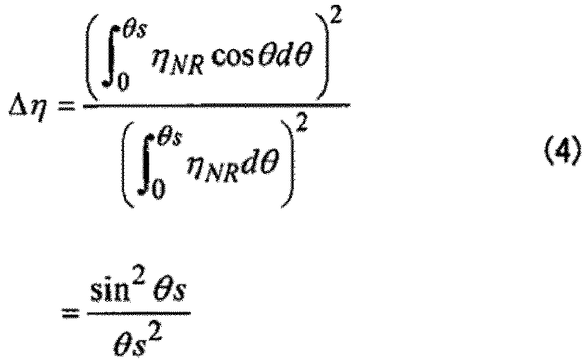
- To maintain the efficiency ratio Δη at Δη > 0.5, from Formula (4), Formula (5) is obtained.
[Math. 5]
- When Formula (5) is plugged in Formula (1), Formula (6) is obtained.
[Math. 6]
- For example, to perform wavelength conversion under a condition of the efficiency ratio Δη > 0.5 over a band of 5 THz, Δv = 5 THz is plugged in Formula (6) and Formula (7) has to be satisfied.
[Math. 7]
- That is, the wavelength converter is designed such that PSD/DGD becomes smaller than 0.56 ps, for example.
- On the other hand, in the configuration of
FIG. 3 of the embodiment, in the case where the nonlinear optical medium 33 with clockwise frequency-dependent polarization rotation and the nonlinear optical medium 34 with counterclockwise frequency-dependent polarization rotation are combined to perform wavelength conversion with a single wavelength of excitation light, Formula (2) is expanded to Formula (8).
[Math. 8]
- L1 is the length of the nonlinear optical medium 33 with clockwise frequency-dependent polarization rotation, and L2 is the length of the nonlinear optical medium 34 with counterclockwise frequency-dependent polarization rotation. The total length L of the nonlinear optical media thus combined is L = L1 + L2.
- When it is assumed that polarization rotation occurs in proportion to the length of each of the nonlinear
optical medium 33 and the nonlinearoptical medium 34, Formula (9) is obtained.
[Math. 9]
- When Formula (9) is plugged in Formula (8), Formula (10) is obtained.
[Math. 10]
- When θ1 = -θ2 = θs/2, Formula (10) is transformed into Formula (11).
[Math. 11]
- When Formula (11) is compared with Formula (4), combining the nonlinear optical medium 33 with clockwise frequency-dependent polarization rotation and the nonlinear optical medium 34 with counterclockwise frequency-dependent polarization rotation makes it possible to compensate for frequency-dependent polarization rotation. That is, as compared with the existing wavelength conversion, it is possible to set the efficiency ratio or PSD/DGD to the same level even when polarization rotation per unit length is twice as large, thus relieving the demand for wavelength conversion, for example.
-
FIG. 8A is a diagram for explaining compensation for polarization crosstalk when using orthogonally polarized two wavelengths of excitation light, andFIG. 8B is a diagram for explaining compensation for polarization crosstalk when using parallel polarized two wavelengths of excitation light. In both of the case of orthogonally polarized two wavelengths of excitation light and the case of parallel polarized two wavelengths of excitation light, polarization crosstalk is generated by polarization rotation between the two beams of excitation light, so that noise is contained in converted signal light, degrading the signal quality. - The polarization crosstalk XT due to polarization rotation between two beams of excitation light where polarization rotation is generated in the longitudinal direction of a nonlinear optical medium is expressed by Formula (12).
[Math. 12]
- The crosstalk XT of Formula (12) is represented by a ratio between the "integral of the component efficiency ηROrth per unit length generated by interaction between orthogonal polarization components generated by the rotation" and the "integral of the component efficiency ηRPara per unit length generated by interaction between parallel polarization components that do not rotate". The orthogonal polarization components and the parallel polarization components mentioned herein refer to components orthogonal to the polarization of incident light and components parallel to the polarization of incident light.
- When it is assumed that the polarization rotates in proportion to the length, Formula (13) is obtained.
[Math. 13]
- When Formula (13) is plugged in Formula (12), Formula (14) is obtained.
[Math. 14]
- To suppress the crosstalk XT to 0.01 or less, the condition of Formula (15) has to be satisfied.
[Math. 15]
- When Formula (15) is plugged in Formula (1), Formula (16) is obtained.
[Math. 16]
- For example, the condition for performing wavelength conversion at a efficiency ratio of Δη > 0.5 over a band of 5 THz is different depending on the arrangement of two beams of excitation light. In the case of wavelength conversion using parallel polarized two wavelengths of excitation light, since the difference in frequency between the two beams of excitation light is approximately 5 THz (see
FIG. 6C ), by plugging Δv = 5 THz in Formula (16), the condition of Formula (17) is obtained.
[Math. 17]
- The wavelength converter has to be designed to satisfy PSD/DGD < 0.08 ps.
- In the case of using orthogonally polarized two wavelengths of excitation light, since the difference in frequency between the two beams of excitation light is approximately 10 THz, which is 2 by 5 THz (see
FIG. 6B ), by plugging Δv = 10 THz in Formula (16), the condition of Formula (18) is obtained.
[Math. 18]
- The wavelength converter has to be designed to satisfy PSD/DGD < 0.04 ps.
- On the other hand, as in the embodiment of
FIG. 3 , in the configuration where the nonlinear optical medium 33 with clockwise frequency-dependent polarization rotation and the nonlinear optical medium 34 with counterclockwise frequency-dependent polarization rotation are combined to perform wavelength conversion with two beams of excitation light, Formula (12) is expanded to Formula (19).
[Math. 19]
- L1 is the length of the nonlinear optical medium 33 with clockwise frequency-dependent polarization rotation, and L2 is the length of the nonlinear optical medium 34 with counterclockwise frequency-dependent polarization rotation. The total length L of the nonlinear optical media thus combined is L = L1 + L2.
- When it is assumed that polarization rotation occurs in proportion to the length of each of the nonlinear
optical medium 33 and the nonlinearoptical medium 34, Formula (20) is obtained.
[Math. 20]
- When Formula (20) is plugged in Formula (19), the crosstalk XT is expressed by Formula (21).
[Math. 21]
- When θ1 = -θ2 = θd/2, Formula (21) is transformed into Formula (22).
[Math. 22]
- When Formula (22) is compared with Formula (14), combining the nonlinear optical medium 33 with clockwise frequency-dependent polarization rotation and the nonlinear optical medium 34 with counterclockwise frequency-dependent polarization rotation makes it possible to suppress the crosstalk to the same level even when the polarization rotation per unit length is twice as large, as compared with the existing configuration. That is, demanded values in the design of a wavelength converter are relieved, for example.
- When the propagation loss is sufficiently small, the difference in propagation constant Δβ among excitation light vP1, excitation light vP2, signal light having a central frequency of vS, and converted light having a central frequency of vC is expressed by Formula (23).
[Math. 23]
- The decrease in efficiency caused by phase mismatch ΔβL generated in a nonlinear optical medium having a length of L due to the difference in propagation constant Δβ, that is, the efficiency ratio Δη is expressed by Formula (24), for example.
[Math. 24]
- The propagation constant β is a function of a frequency, and the Taylor expansion around v0 is expressed by Formula (25) when fifth-order or more terms are ignored.
[Math. 25]
- In the case of a single wavelength of excitation light, when the excitation light frequency and the zero-dispersion frequency are made coincident (v0 = vP), the average of the frequency vS of signal light and the frequency vC of converted light coincides with the zero-dispersion frequency (v0 = (vS + vC)/2), and the difference in propagation constant Δβ is expressed by Formula (26) where terms other than the fourth-order term are canceled out.
[Math. 26]
- When the band of Δv is converted, the efficiency is the lowest when vS = v0 ± Δv, and Formula (26) is transformed into Formula (27).
[Math. 27]
- In the case of wavelength conversion using orthogonally polarized two wavelengths of excitation light, when the average value of the frequencies of the two excitation light beams and the zero-dispersion frequency are made coincident (v0 = (vP1 + vP2)/2), the average of the frequency vS of signal light and the frequency vC of converted light coincides with the zero-dispersion frequency (v0 = (vS + vC)/2), and the difference in propagation constant Δβ is expressed by Formula (28) where terms other than the fourth-order term are canceled out.
[Math. 28]
- When the band of Δv is converted, the efficiency is the lowest when vS = v0 and vP1,2 = v0 ± Δv, which is equal to Formula (27).
- In either case of a single wavelength of excitation light and orthogonally polarized two wavelengths of excitation light, to suppress the efficiency ratio to Δη > 0.5, the absolute value of the fourth derivative of the propagation constant β with the frequency v has to satisfy the condition of Formula (29) which is obtained by plugging Formula (27) in Formula (24).
[Math. 29]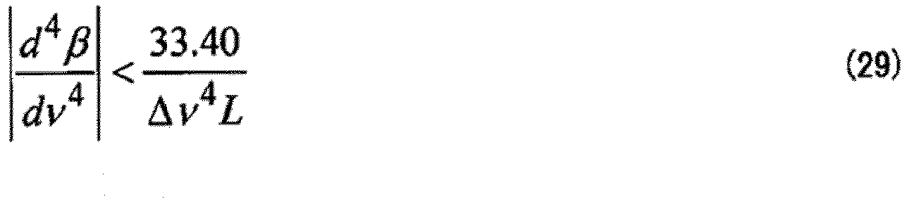
- For example, to convert a band of 5 THz with a nonlinear optical medium of 100 m, Formula (30) has to be satisfied.
[Math. 30]
- In contrast, combining a nonlinear optical medium having a length of 50 m with which the value of the fourth derivative d4β/dv4 is positive and a nonlinear optical medium having a length of 50 m with which the value of the fourth derivative is negative as in the embodiment makes it possible to relieve the demanded value as described later.
- When the zero-dispersion frequency (second-order dispersion is zero) of a nonlinear optical medium is v0 and the average value of the frequencies of the two excitation light beams and the zero-dispersion frequency are made coincident (v0 = (vP1 + vP2)/2, vP1 = v0 - Δv/2, vP2 = v0 + Δv/2), and the frequency vC of converted light is vC = vS + Δv. When the band of Δv is converted, the efficiency is the lowest when vS = v0 or vS = v0 - Δv.
- When the fourth-order derivative is sufficiently small, the difference in propagation constant Δβ is expressed by Formula (31) from Formula (25) where terms other than the third-order term is canceled out.
[Math. 31]
- To maintain the efficiency ratio at Δη > 0.5, the absolute value of the third derivative of the propagation constant β with the frequency v has to satisfy the condition of Formula (32). Formula (32) is obtained by plugging Formula (24) in Formula (31).
[Math. 32]
- For example, to convert a band of 5 THz with a nonlinear optical medium of 100 m, the wavelength converter has to be designed to satisfy formula (33).
[Math. 33]
- Combining nonlinear optical media having different, positive and negative, dispersions as in the embodiment makes it possible to relieve the demand in design as described below.
- That is, for example, in the case where the nonlinear optical medium 33 having a length of L1 in the optical axis direction and a propagation constant of β1 and a nonlinear optical medium 34 having a length of L2 and a propagation constant of β2 are combined (L1 + L2 = L), Formula (24) is expanded to Formula (34).
[Math. 34]
- When Δβ = -Δβ2 = Δβp, L1 = L2 = L/2, the efficiency ratio Δη is expressed by Formula (35).
[Math. 35]
- Δβp is a function of only the fourth-order dispersion in the case of wavelength dispersion with a single wavelength of excitation light and orthogonally polarized two wavelengths of excitation light, and is a function of only the third-order dispersion in the case of wavelength dispersion with parallel polarized two wavelengths of excitation light. When Formula (35) is compared with Formula (24), combining nonlinear optical media having a positive dispersion value and a negative dispersion value as in the embodiment makes it possible to relieve the demand as compared with the case of using a single nonlinear optical medium. Specifically, it is possible to suppress a decrease in efficiency due to the crosstalk to the same level even when the fourth-order dispersion or the third-order dispersion per unit length is twice those of Formula (29) or Formula (32), for example.
-
FIG. 9 is a schematic diagram of awavelength converter 30A. Thewavelength converter 30A is applied to wavelength conversion using a single wavelength of excitation light and orthogonally polarized two wavelengths of excitation light, and compensates for spectrum degradation due to fourth-order dispersion as described above. - The
wavelength converter 30A includes anoptical multiplexer 31, anexcitation light source 32, a first nonlinearoptical medium 133 having a positive fourth-order dispersion value, a second nonlinearoptical medium 134 having a negative fourth-order dispersion value, and anoptical filter 35. The length of the first nonlinearoptical medium 133 and the length of the second nonlinearoptical medium 134 in the optical axis direction are designed such that the relative differential group delay or the phase mismatch between incident light and converted signal light becomes minimum at the exit plane of the second nonlinear optical medium. - The order of arrangement of the nonlinear
optical medium 133 having a positive fourth-order dispersion value and the nonlinearoptical medium 134 having a negative fourth-order dispersion value may be reversed. Two sets or more of nonlinear optical media may be used and arranged such that positive and negative fourth-order dispersion values are arranged alternately. - This
wavelength converter 30A allows fourth-order dispersion having a size twice that of the case of using a single nonlinear optical medium at the same efficiency ratio (or a decrease in efficiency). -
FIG. 10 is a diagram for explaining the effect of thewavelength converter 30A ofFIG. 9 . The horizontal axis indicates the propagation position in the nonlinear optical medium, that is, the distance from the incidence plane of the first nonlinearoptical medium 133, for example. It is assumed that the first nonlinearoptical medium 133 and the second nonlinearoptical medium 134 continue in the optical axis direction and the influence of the interface therebetween may be ignored. - The vertical axis indicates the relative differential group delay between input signal light and converted signal light. As propagation in the first nonlinear optical medium 133 proceeds, the relative differential group delay increases upon the influence of fourth-order dispersion, and phase deviation between the input signal light and the converted signal light increases. However, propagation in the second nonlinear
optical medium 134 having a fourth-order dispersion value of the opposite sign reduces the relative differential group delay, so that the relative differential group delay becomes minimum at the output plane of the second nonlinearoptical medium 134. - This makes it possible to suppress a decrease in conversion efficiency due to phase mismatch between light waves.
-
FIG. 11 is a schematic diagram of awavelength converter 30B. Thewavelength converter 30B is applied to wavelength conversion using parallel polarized two wavelengths of excitation light, and compensates for spectrum degradation due to third-order dispersion as described above. - The
wavelength converter 30B includes anoptical multiplexer 31, anexcitation light source 32, a first nonlinearoptical medium 233 having a positive third-order dispersion value, a second nonlinearoptical medium 234 having a negative third-order dispersion value, and anoptical filter 35. The length of the first nonlinearoptical medium 233 and the length of the second nonlinearoptical medium 234 in the optical axis direction are designed such that the relative differential group delay or the phase mismatch between incident light and converted signal light becomes minimum at the exit plane of the second nonlinear optical medium. - The order of arrangement of the nonlinear
optical medium 233 having a positive third-order dispersion value and the nonlinearoptical medium 234 having a negative third-order dispersion value may be reversed. Two sets or more of nonlinear optical media may be used and arranged such that positive and negative third-order dispersion values are arranged alternately. - This
wavelength converter 30B allows third-order dispersion having a size twice that of the case of using a single nonlinear optical medium at the same efficiency ratio (or a decrease in efficiency). -
FIG. 12 is a diagram for explaining the effect of thewavelength converter 30B ofFIG. 11 . The horizontal axis indicates the propagation position in the nonlinear optical medium, that is, the distance from the incidence plane of the first nonlinearoptical medium 233, for example. It is assumed that the first nonlinearoptical medium 233 and the second nonlinearoptical medium 234 continue in the optical axis direction and the influence of the interface therebetween may be ignored. - The vertical axis indicates the relative differential group delay between input signal light and converted signal light. As propagation in the first nonlinear optical medium 233 proceeds, the relative differential group delay increases upon the influence of third-order dispersion, and phase deviation between the input signal light and the converted signal light increases. However, propagation in the second nonlinear
optical medium 234 having a third-order dispersion value of the opposite sign reduces the relative differential group delay, so that the relative differential group delay becomes minimum at the output plane of the second nonlinearoptical medium 234. - This makes it possible to suppress a decrease in conversion efficiency due to phase mismatch between light waves.
- All of the
wavelength converters optical communication devices FIG. 2 . Controlling the wavelength vp of excitation light makes it possible to convert input signal light to a desired wavelength band (the L band, the S band, or the like). In theoptical communication devices - The wavelength conversion of the embodiment encompasses overall optical parametric amplifications including generation of sum frequency or difference frequency, generation of harmonic, optical parametric oscillation, and the like. Hence, for example, when a "wavelength converter" is mentioned in claims, it encompasses a sum frequency generator, a difference frequency generator, a harmonic generator, optical parametric oscillator, optical parametric amplifier, and the like.
- In the case where the embodiment is applied to an optical parametric amplifier or the like as well, a first nonlinear optical medium and a second nonlinear optical medium having different optical properties (or different signs) from each other are combined. Excitation light having a first wavelength, excitation light having a second wavelength, and signal light having a third wavelength are made incident on a first nonlinear optical medium to generate idler light having a fourth wavelength.
- The length (L1) of the first nonlinear optical medium and the length (L2) of the second nonlinear optical medium in the optical axis direction are designed such that at least one of the relative differential group delay (or the phase mismatch) of the converted signal light relative to the input signal light and the relative polarization angle between the input signal light and the excitation light is minimized at the exit plane of the second nonlinear optical medium.
- The wavelength conversion or optical parametric amplification using a single wavelength of excitation light may be considered as the case where the first excitation light and the second excitation light have the same wavelength or frequency in a four-wave mixing. The excitation light source may be a light source outside the wavelength converter or optical parametric amplifier. Excitation light may be made incident on the first nonlinear optical medium through an optical waveguide such as an optical fiber, for example.
Claims (11)
- An optical communication device comprising:an excitation light source that outputs excitation light;a multiplexer that multiplexes signal light and the excitation light outputted from the excitation light source;a first nonlinear optical medium into which the multiplexed excitation light and the signal light are inputted; anda second nonlinear optical medium that is coupled to the first nonlinear optical medium in series and has an optical property different from that of the first nonlinear optical medium.
- The optical communication device according to claim 1, wherein
the first nonlinear optical medium generates polarization rotation in a first direction, depending on a frequency of a light wave propagating in the first nonlinear optical medium, and
the second nonlinear optical medium generates polarization rotation in a second direction opposite to the first direction, depending on the frequency. - The optical communication device according to claim 1, wherein
in the first nonlinear optical medium, a fourth derivative relating to a frequency of a propagation constant has a first sign, and
in the second nonlinear optical medium, the fourth derivative has a second sign different from the first sign. - The optical communication device according to claim 1, wherein
in the first nonlinear optical medium, a third derivative relating to a frequency of a propagation constant has a first sign, and
in the second nonlinear optical medium, the third derivative has a second sign different from the first sign. - The optical communication device according to claim 1, wherein
a length of the first nonlinear optical medium in an optical axis direction and a length of the second nonlinear optical medium in the optical axis direction are designed such that at least one of relative differential group delay of the converted signal light relative to the input signal light and a relative polarization angle between excitation light inputted to the first nonlinear optical medium and the input signal light is minimized at an exit plane of the second nonlinear optical medium. - A transmission system comprising:a first multiplexer that performs wavelength multiplexing on an optical signal having a wavelength in a first waveband;a second multiplexer that performs wavelength multiplexing on an optical signal having a wavelength in the first waveband;a wavelength converter that converts a wavelength multiplexed signal outputted from the second multiplexer to a wavelength in a second waveband different from the first waveband; anda third multiplexer that multiplexes a wavelength multiplexed signal outputted from the first multiplexer and a wavelength multiplexed signal outputted from the wavelength converter, whereinthe wavelength converter includes:a first nonlinear optical medium; anda second nonlinear optical medium that is coupled to the first nonlinear optical medium in series and has an optical property different from that of the first nonlinear optical medium.
- The transmission system according to claim 6, wherein
the first nonlinear optical medium generates polarization rotation in a first direction, depending on a frequency of a light wave propagating in the first nonlinear optical medium, and
the second nonlinear optical medium generates polarization rotation in a second direction opposite to the first direction, depending on the frequency. - A wavelength converter comprising:a first nonlinear optical medium; anda second nonlinear optical medium that has an optical property different from that of the first nonlinear optical medium, whereinthe wavelength converter generates idler light having a third wavelength from input signal light having a first wavelength inputted into the first nonlinear optical medium and excitation light having a second wavelength different from the first wavelength, and outputs the idler light from the second nonlinear optical medium.
- The wavelength converter according to claim 8, wherein
the first nonlinear optical medium generates polarization rotation in a first direction, depending on a frequency of a light wave propagating in the first nonlinear optical medium, and
the second nonlinear optical medium generates polarization rotation in a second direction opposite to the first direction, depending on the frequency. - An optical communication method comprising:making input signal light having a first wavelength and excitation light having a second wavelength different from the first wavelength incident on a wavelength converter in which a first nonlinear optical medium and a second nonlinear optical medium having an optical property different from that of the first nonlinear optical medium are coupled in series, to generate converted signal light having a third wavelength different from the first wavelength and the second wavelength; andoutputting, to an optical transmission path, the converted signal light outputted from the second nonlinear optical medium.
- The optical communication method according to claim 10, wherein
the first nonlinear optical medium generates polarization rotation in a first direction, depending on a frequency of a light wave propagating in the first nonlinear optical medium, and
the second nonlinear optical medium generates polarization rotation in a second direction opposite to the first direction, depending on the frequency.
Applications Claiming Priority (1)
| Application Number | Priority Date | Filing Date | Title |
|---|---|---|---|
| JP2019029740A JP7188173B2 (en) | 2019-02-21 | 2019-02-21 | Optical communication device, optical transmission system, wavelength converter, and optical communication method |
Publications (1)
| Publication Number | Publication Date |
|---|---|
| EP3716503A1 true EP3716503A1 (en) | 2020-09-30 |
Family
ID=69411308
Family Applications (1)
| Application Number | Title | Priority Date | Filing Date |
|---|---|---|---|
| EP20154573.8A Withdrawn EP3716503A1 (en) | 2019-02-21 | 2020-01-30 | Optical communication device, optical transmission system, wavelength converter, and optical communication method |
Country Status (4)
| Country | Link |
|---|---|
| US (1) | US11668870B2 (en) |
| EP (1) | EP3716503A1 (en) |
| JP (1) | JP7188173B2 (en) |
| CN (1) | CN111600673A (en) |
Families Citing this family (1)
| Publication number | Priority date | Publication date | Assignee | Title |
|---|---|---|---|---|
| JP2024046500A (en) * | 2022-09-22 | 2024-04-03 | 富士通株式会社 | Wavelength converters and optical transmission systems |
Citations (4)
| Publication number | Priority date | Publication date | Assignee | Title |
|---|---|---|---|---|
| EP1298485A2 (en) * | 2001-09-28 | 2003-04-02 | Fujitsu Limited | Method, device, and system for waveform shaping of signal light |
| JP2007017907A (en) | 2005-07-11 | 2007-01-25 | Sumitomo Electric Ind Ltd | Optical fiber and optical device using the same |
| EP2083320A1 (en) * | 2008-01-25 | 2009-07-29 | Fujitsu Limited | Optical signal processing apparatus, optical receiving apparatus, and optical relay apparatus |
| WO2018198478A1 (en) * | 2017-04-28 | 2018-11-01 | 富士通株式会社 | Transmission device and transmission method |
Family Cites Families (14)
| Publication number | Priority date | Publication date | Assignee | Title |
|---|---|---|---|---|
| JP3419510B2 (en) * | 1992-10-16 | 2003-06-23 | 富士通株式会社 | Optical communication system with chromatic dispersion compensation and phase conjugate light generator applicable to the system |
| JPH0784289A (en) * | 1993-09-13 | 1995-03-31 | Nippon Telegr & Teleph Corp <Ntt> | Optical frequency converter |
| JPH08278148A (en) * | 1995-04-03 | 1996-10-22 | Furukawa Electric Co Ltd:The | Optical fiber coil |
| US5960146A (en) | 1996-07-24 | 1999-09-28 | Sumitomo Electric Industries, Ltd. | Optical fiber and light source apparatus |
| JP3975202B2 (en) | 1996-07-24 | 2007-09-12 | 住友電気工業株式会社 | Optical fiber and light source device |
| JP2001242336A (en) * | 1999-12-22 | 2001-09-07 | Furukawa Electric Co Ltd:The | Optical fiber, dispersion compensator using the same, optical transmission line, and optical transmission system |
| US7079737B1 (en) * | 2002-10-11 | 2006-07-18 | Corning Incorporated | Devices and methods for dynamic dispersion compensation |
| US7136558B2 (en) * | 2003-04-29 | 2006-11-14 | Nortel Networks Limited | Optical waveguide |
| US7869680B2 (en) * | 2004-07-02 | 2011-01-11 | Olambda, Inc. | Nonlinearity compensation in a fiber optic communications system |
| US7233727B2 (en) | 2005-07-11 | 2007-06-19 | Sumitomo Electric Industries, Ltd. | Optical fiber and optical device using the same |
| JP4492498B2 (en) | 2005-09-07 | 2010-06-30 | 住友電気工業株式会社 | Optical fiber and optical device using the same |
| JP2008152133A (en) | 2006-12-19 | 2008-07-03 | Sumitomo Electric Ind Ltd | Wavelength converter |
| JP5347333B2 (en) * | 2008-05-23 | 2013-11-20 | 富士通株式会社 | Optical signal processing device |
| WO2011115293A1 (en) * | 2010-03-19 | 2011-09-22 | 古河電気工業株式会社 | Polarization independent wavelength conversion device and method of converting polarization independent wavelength |
-
2019
- 2019-02-21 JP JP2019029740A patent/JP7188173B2/en active Active
-
2020
- 2020-01-30 EP EP20154573.8A patent/EP3716503A1/en not_active Withdrawn
- 2020-02-04 US US16/781,103 patent/US11668870B2/en active Active
- 2020-02-19 CN CN202010102118.0A patent/CN111600673A/en active Pending
Patent Citations (4)
| Publication number | Priority date | Publication date | Assignee | Title |
|---|---|---|---|---|
| EP1298485A2 (en) * | 2001-09-28 | 2003-04-02 | Fujitsu Limited | Method, device, and system for waveform shaping of signal light |
| JP2007017907A (en) | 2005-07-11 | 2007-01-25 | Sumitomo Electric Ind Ltd | Optical fiber and optical device using the same |
| EP2083320A1 (en) * | 2008-01-25 | 2009-07-29 | Fujitsu Limited | Optical signal processing apparatus, optical receiving apparatus, and optical relay apparatus |
| WO2018198478A1 (en) * | 2017-04-28 | 2018-11-01 | 富士通株式会社 | Transmission device and transmission method |
Non-Patent Citations (1)
| Title |
|---|
| KATSUMI UESAKA ET AL.: "WAVELENGTH EXCHANGE IN A HIGHLY NONLINEAR DISPERSION-SHIFTED FIBER: THEORY AND EXPERIMENTS", IEEE JOURNAL OF SELECTED TOPICS IN QUANTUM ELECTRONICS, vol. 8, no. 3, May 2002 (2002-05-01), XP011066162 |
Also Published As
| Publication number | Publication date |
|---|---|
| US11668870B2 (en) | 2023-06-06 |
| US20200271855A1 (en) | 2020-08-27 |
| CN111600673A (en) | 2020-08-28 |
| JP7188173B2 (en) | 2022-12-13 |
| JP2020134776A (en) | 2020-08-31 |
Similar Documents
| Publication | Publication Date | Title |
|---|---|---|
| US5532868A (en) | Apparatus and method for compensating chromatic dispersion produced in optical phase conjugation or other types of optical signal conversion | |
| EP0987583B1 (en) | Polarisation-independent phase-conjugation apparatus and system comprising this apparatus | |
| US7200333B2 (en) | Optical communication apparatus, system, and method that properly compensate for chromatic dispersion | |
| US6626592B2 (en) | Optical communication system using optical phase conjugation to suppress waveform distortion caused by chromatic dispersion and optical Kerr effect | |
| Watanabe et al. | Simultaneous wavelength conversion and optical phase conjugation of 200 Gb/s (5/spl times/40 Gb/s) WDM signal using a highly nonlinear fiber four-wave mixer | |
| US6954303B2 (en) | Multi-stage optical amplifier and broadband communication system | |
| WO1998008138A1 (en) | Optical fiber communication system using optical phase conjugate, apparatus applicable to the system and its manufacturing method | |
| US20040175187A1 (en) | Single fiber duplex optical transport | |
| US7408701B2 (en) | Multi-frequency light source | |
| US20030198448A1 (en) | Dispersion map for slope compensating fibers | |
| US20020163689A1 (en) | Method and apparatus for wavelength conversion | |
| Bigo et al. | Investigation of cross-phase modulation limitation over various types of fiber infrastructures | |
| EP3716503A1 (en) | Optical communication device, optical transmission system, wavelength converter, and optical communication method | |
| WO2006089356A1 (en) | Optical commmunications system | |
| GB2330026A (en) | WDM optical signal dispersion compensation | |
| US20040258352A1 (en) | Variable dispersion compensator utilizing wavelength conversion | |
| EP1387510A1 (en) | One-core two-way optical transmission system | |
| JP3494738B2 (en) | Optical fiber communication system using optical phase conjugation | |
| US6856451B2 (en) | Optical communication system | |
| US6026204A (en) | Matching apparatus for an optical communications network | |
| US20250004351A1 (en) | Broadband Source of Quantum-Entangled Photons | |
| US20260019155A1 (en) | Optical transmission node, wavelength converter, and method for driving wavelength converter | |
| US11387912B2 (en) | Wavelength converter and fiber optic transmission system | |
| JP2006129503A (en) | OPTICAL NETWORK, OPTICAL TRANSMITTER, OPTICAL RECEIVER, OPTICAL AMPLIFIER, DISPERSION COMPENSATOR, SIGNAL LIGHT WAVELENGTH SELECTION METHOD IN OPTICAL NETWORK, WAVELENGTH MULTIPLEXER | |
| US20250047382A1 (en) | Optical transmission system, optical transmission method and program |
Legal Events
| Date | Code | Title | Description |
|---|---|---|---|
| PUAI | Public reference made under article 153(3) epc to a published international application that has entered the european phase |
Free format text: ORIGINAL CODE: 0009012 |
|
| STAA | Information on the status of an ep patent application or granted ep patent |
Free format text: STATUS: THE APPLICATION HAS BEEN PUBLISHED |
|
| AK | Designated contracting states |
Kind code of ref document: A1 Designated state(s): AL AT BE BG CH CY CZ DE DK EE ES FI FR GB GR HR HU IE IS IT LI LT LU LV MC MK MT NL NO PL PT RO RS SE SI SK SM TR |
|
| AX | Request for extension of the european patent |
Extension state: BA ME |
|
| STAA | Information on the status of an ep patent application or granted ep patent |
Free format text: STATUS: REQUEST FOR EXAMINATION WAS MADE |
|
| 17P | Request for examination filed |
Effective date: 20210218 |
|
| RBV | Designated contracting states (corrected) |
Designated state(s): AL AT BE BG CH CY CZ DE DK EE ES FI FR GB GR HR HU IE IS IT LI LT LU LV MC MK MT NL NO PL PT RO RS SE SI SK SM TR |
|
| STAA | Information on the status of an ep patent application or granted ep patent |
Free format text: STATUS: THE APPLICATION HAS BEEN WITHDRAWN |
|
| 18W | Application withdrawn |
Effective date: 20220427 |