EP3716459A1 - Power factor correcting method - Google Patents
Power factor correcting method Download PDFInfo
- Publication number
- EP3716459A1 EP3716459A1 EP20163394.8A EP20163394A EP3716459A1 EP 3716459 A1 EP3716459 A1 EP 3716459A1 EP 20163394 A EP20163394 A EP 20163394A EP 3716459 A1 EP3716459 A1 EP 3716459A1
- Authority
- EP
- European Patent Office
- Prior art keywords
- power factor
- ref
- xcap
- correcting method
- factor correcting
- Prior art date
- Legal status (The legal status is an assumption and is not a legal conclusion. Google has not performed a legal analysis and makes no representation as to the accuracy of the status listed.)
- Granted
Links
Images


Classifications
-
- H—ELECTRICITY
- H02—GENERATION; CONVERSION OR DISTRIBUTION OF ELECTRIC POWER
- H02M—APPARATUS FOR CONVERSION BETWEEN AC AND AC, BETWEEN AC AND DC, OR BETWEEN DC AND DC, AND FOR USE WITH MAINS OR SIMILAR POWER SUPPLY SYSTEMS; CONVERSION OF DC OR AC INPUT POWER INTO SURGE OUTPUT POWER; CONTROL OR REGULATION THEREOF
- H02M1/00—Details of apparatus for conversion
- H02M1/42—Circuits or arrangements for compensating for or adjusting power factor in converters or inverters
- H02M1/4208—Arrangements for improving power factor of AC input
- H02M1/4216—Arrangements for improving power factor of AC input operating from a three-phase input voltage
-
- H—ELECTRICITY
- H02—GENERATION; CONVERSION OR DISTRIBUTION OF ELECTRIC POWER
- H02M—APPARATUS FOR CONVERSION BETWEEN AC AND AC, BETWEEN AC AND DC, OR BETWEEN DC AND DC, AND FOR USE WITH MAINS OR SIMILAR POWER SUPPLY SYSTEMS; CONVERSION OF DC OR AC INPUT POWER INTO SURGE OUTPUT POWER; CONTROL OR REGULATION THEREOF
- H02M1/00—Details of apparatus for conversion
- H02M1/42—Circuits or arrangements for compensating for or adjusting power factor in converters or inverters
- H02M1/4208—Arrangements for improving power factor of AC input
- H02M1/4225—Arrangements for improving power factor of AC input using a non-isolated boost converter
-
- G—PHYSICS
- G05—CONTROLLING; REGULATING
- G05F—SYSTEMS FOR REGULATING ELECTRIC OR MAGNETIC VARIABLES
- G05F1/00—Automatic systems in which deviations of an electric quantity from one or more predetermined values are detected at the output of the system and fed back to a device within the system to restore the detected quantity to its predetermined value or values, i.e. retroactive systems
- G05F1/70—Regulating power factor; Regulating reactive current or power
-
- H—ELECTRICITY
- H02—GENERATION; CONVERSION OR DISTRIBUTION OF ELECTRIC POWER
- H02M—APPARATUS FOR CONVERSION BETWEEN AC AND AC, BETWEEN AC AND DC, OR BETWEEN DC AND DC, AND FOR USE WITH MAINS OR SIMILAR POWER SUPPLY SYSTEMS; CONVERSION OF DC OR AC INPUT POWER INTO SURGE OUTPUT POWER; CONTROL OR REGULATION THEREOF
- H02M1/00—Details of apparatus for conversion
- H02M1/42—Circuits or arrangements for compensating for or adjusting power factor in converters or inverters
- H02M1/4208—Arrangements for improving power factor of AC input
-
- G—PHYSICS
- G01—MEASURING; TESTING
- G01R—MEASURING ELECTRIC VARIABLES; MEASURING MAGNETIC VARIABLES
- G01R21/00—Arrangements for measuring electric power or power factor
- G01R21/006—Measuring power factor
-
- H—ELECTRICITY
- H02—GENERATION; CONVERSION OR DISTRIBUTION OF ELECTRIC POWER
- H02M—APPARATUS FOR CONVERSION BETWEEN AC AND AC, BETWEEN AC AND DC, OR BETWEEN DC AND DC, AND FOR USE WITH MAINS OR SIMILAR POWER SUPPLY SYSTEMS; CONVERSION OF DC OR AC INPUT POWER INTO SURGE OUTPUT POWER; CONTROL OR REGULATION THEREOF
- H02M1/00—Details of apparatus for conversion
- H02M1/0003—Details of control, feedback or regulation circuits
- H02M1/0012—Control circuits using digital or numerical techniques
Definitions
- the present disclosure relates to a power factor correcting method, and in particular, to a power factor correcting method which corrects a power factor in an alternating current (AC) power supply.
- AC alternating current
- an electromagnetic interference (EMI) filter is generally used to suppress conductive noises generated by the switching-type AC power supply.
- EMI electromagnetic interference
- an X-capacitor (X-cap) is connected to an input line and acts as a low-pass filter for differential noises.
- PFC power factor corrector
- Non-Patent Document 1 describes a theory and implementation method of how to compensate for the X-cap reactive current.
- a new reference current is obtained by subtracting the X-cap reactive current from a reference current, and the new reference current is applied to the PFC current loop.
- ADC analog-digital converter
- RAM random access memory
- Non-Patent Document 1 it requires too much storage space in RAM to calculate the reference current for the X-cap reactive current. In addition, it usually takes a lot of time resources to perform calculations for each sampling period. This may result in a low code efficiency and an increase of cost of expensive high-performance microcontroller units (MCUs).
- MCUs microcontroller units
- Patent Document 1 A similar method of delaying the PFC current has been proposed in Patent Document 1, but a method of compensating for the X-cap current thereof is different from that of Non-Patent Document 1.
- second harmonics are actually obtained from an output power, and then the second harmonic components are injected into a voltage control of the PFC, so that the power supply can change a leading power factor into a lagging power factor.
- a second harmonic frequency used for compensation is not exactly an X-cap current waveform, because the X-cap current has a sine frequency that is the same as a line frequency but advances 90 degrees in phase, which is actually roughly a composite input current.
- the X-cap current should be irrelevant to the output power.
- the compensation amplitude becomes relatively high, which causes a non-sine input current when the power supply is at a relatively high load.
- Non-Patent Document 1 Increase power factor by digitally compensating for PFC EMI-capacitor reactive current, http://www.ti.com/lit/an/slyt673/slyt673 .pdf
- Patent Document 1 US8872484B2
- the present disclosure has been made in view of the above, and an object thereof is to provide a new method for power factor correction that can effectively compensate for a reactive current of an EMI capacitor, thereby improving a power factor and reducing a current harmonic distortion. Accordingly, compared with the existing methods, code efficiency can be improved, and a microcontroller unit can generate a continuous reactive current of the EMI capacitor with less computing resources.
- a power factor correcting method for correcting a power factor of an AC power supply comprising: detecting zero-crossing points of an input voltage V AC of the AC power supply to obtain a period T of the V AC ; generating a half-wave symmetric periodic function f(t) by using the period T; implementing a recursive low-pass filter y(t) by using the f(t), so that an output of the y(t) matches a target reactive current I xcap (t) flowing through an X-capacitor; generating a reference current I ref ⁇ t for correcting the power factor by using a given reference current I ref ( t ) and the y(t); and correcting the power factor by using the reference current I ref ⁇ t .
- a simple half-wave symmetric function is generated digitally by the MCU and then a recursive low-pass filter is used to match the reactive current of the EMI capacitor, thereby obtaining a new reference current for a power factor corrector.
- the reactive current of the EMI capacitor can be effectively compensated, thereby improving the power factor and reducing the current harmonic distortion, and compared with the existing methods, the code efficiency can be improved, and the microcontroller unit can generate a continuous reactive current of the EMI capacitor with less computing resources.
- FIG. 1 illustrates a schematic diagram of a power factor correcting configuration according to the prior art.
- 101 denotes an alternating current power supply (AC power supply) for supplying power to the PFC
- 102 denotes an EMI filter for suppressing conductive noises (including common mode and differential mode)
- 103 denotes a PFC circuit, which changes a waveform of the current supplied to a load to increase the power factor
- 104 denotes a load corresponding to an output of the PFC.
- a rectifier circuit is provided inside the PFC circuit 103.
- FIG. 2 schematically illustrates an equivalent circuit diagram of main parts of a power supply unit having an X-cap.
- a simplified EMI filter is shown in FIG. 2 .
- An equivalent circuit of a differential input of the PFC is similar to a capacitor 202 before the PFC 203, because the common mode choke is not affected.
- I AC denotes a current provided by AC power supply 201
- I xcap denotes a reactive current flowing through the X-cap
- I L denotes a current flowing through the PFC.
- A denotes a loop output voltage that changes with the load
- B denotes 1 RMS V AC 2
- I ref denotes a function that changes over time.
- I L is in phase with V AC .
- C xcap denotes a capacitance of the X-cap
- d dt denotes a time derivative
- V AC ( t ) denotes an instantaneous input voltage
- FIG. 3 illustrates a schematic diagram of a composite input waveform without X-cap compensation.
- I AC is ahead of V AC due to the effect of I xcap , which would result in a poor power factor.
- Power factor cos ⁇ 1 + iTHD 2
- cos ⁇ denotes a phase shift power factor
- 1 1 + iTHD 2 denotes a distortion power factor
- iTHD denotes a total harmonic distortion of the load current
- I L may be modified to achieve a unit power factor.
- I ref ⁇ t denotes a new reference current that changes over time
- I xcap (t) denotes a reactive current flowing through the X-cap calculated by the microcontroller unit using Equation 3.
- FIG. 4 illustrates a schematic diagram of a composite input waveform with X-cap compensation. The results after performing the X-cap compensation are illustrated in FIG. 4 . As illustrated in FIG. 4 , composite I AC is in phase with V AC and a power factor is close to 1.
- a key factor to implement the X-cap compensation is to generate, within the microcontroller unit, a reactive current flowing through the X-cap, that is, I xcap ( t ) .
- the reactive current I xcap ( t ) may also be detected by an isolated-type current meter, such as a Hall effect sensor.
- the reactive current I xcap ( t ) is preferably obtained by an algorithm in the microcontroller unit.
- Non-Patent Document 1 it is proposed to use a internal random access memory (RAM) to continuously record V AC to obtain cos(2 ⁇ ft).
- RAM internal random access memory
- a large amount of RAM storage space is occupied, and it is proportional to a sampling rate in a half period of V AC .
- the inventor of the present invention after research, has proposed a new power factor correcting method.
- the reactive current of the EMI capacitor can be effectively compensated, and accordingly, the power factor can be improved and the current harmonic distortion can be reduced, and compared with the existing methods, code efficiency can be increased, and the microcontroller unit can generate a continuous reactive current of the EMI capacitor with less computing resources.
- a power factor correcting method in the present disclosure By applying the power factor correcting method of the present disclosure to a reference current calculation to compensate for the reactive current of an EMI capacitor, the power factor of a switching-type AC power supply can be improved, and the current harmonic distortion can be reduced.
- FIG. 5 illustrates a flowchart of generating a new reference current using X-cap compensation according to an embodiment of the present disclosure.
- FIG. 5 An output of the flowchart as illustrated in FIG. 5 is a new reference current I ref ⁇ , which is periodically updated after I ref .
- Step 501 V AC zero-crossing points are digitally detected from a AC power supply (referring to the AC power supply 101 of the circuit illustrated in FIG. 1 and the AC power supply 201 of the circuit illustrated in FIG. 2 ), to obtain a period of V AC and set the period of V AC to T.
- the period T is used to generate a periodic function with half-wave symmetry, that is, a half-wave symmetric function f ( t ) .
- Any type of periodic function may be generated in Step 502, as long as it has half-wave symmetry, such as square wave, triangular wave, trapezoidal wave, etc. The simpler the function is, the higher the code efficiency can be.
- the half-wave symmetric function f ( t ) may be generated using Equation 7 below, and the period of the half-wave symmetric function generated in this embodiment is equal to the period of V AC .
- f t ⁇ f t ⁇ T 2
- T denotes the period of V AC .
- a recursive filter y (t) is applied to the half-wave symmetric function f ( t ) to generate an approximately sine waveform.
- the recursive filter y (t) is a low-pass filter. That is, the recursive low-pass filter y (t) is implemented using the half-wave symmetric function f ( t ) .
- y ( t ) can be any type of recursive filter using one or more outputs as input. For example, Equation 9 as described in the following may be used to obtain the recursive filter y ( t ), by a simple replacement of ⁇ ( t ) in Equation 9 with f ( t ) .
- the characteristic of the recursive filter y ( t ) is to smooth the periodic function generated in Step 502 and is preferably capable of significantly attenuating relatively high frequency components after many V AC periods.
- the obtained recursive filter y ( t ) can be represented as a sine wave with a baseline frequency, which looks like a reactive current I xcap flowing through the X-cap, but may have different amplitudes and phase shifts.
- a complex mathematical method may be used to calculate a gain and phase shift to adjust the amplitude and phase of y ( t ) so as to match the amplitude and phase shift of I xcap .
- steps 504, 505, 506, and 507 in FIG. 5 are used to provide a preferred and simpler iterative method to adjust the amplitude and phase shift of y ( t ).
- the microcontroller unit MCU may derive y ( t ), as well as I ref ( t ) which is calculated from the voltage of the AC power supply and the loop output voltage using the above Equation 2, and verify whether the amplitude and phase of y ( t ) match the target I xcap ( t ) calculated using the above Equation 3. If it is No in Step 506, then in Step 507, a gain is adjusted, and in Step 504, the adjusted gain is used as a multiplication coefficient to compensate for y ( t ) to adjust the amplitude of y ( t ).
- Step 505 the phase of y ( t ) is adjusted to advance V AC by a given threshold.
- the amplitude and phase of y ( t ) can be approximately consistent with the target I xcap ( t ) through several iterations.
- the given threshold is preferably in a range of 85 degrees to 95 degrees, and more preferably is 90 degrees.
- a new reference current I ref ⁇ t may be obtained through steps 508, 509, 510, and 511 shown in FIG. 5 .
- Step 508 it is determined whether the target I ref ( t ) is greater than the absolute value of y ( t ).
- steps 504, 505, 506, and 507 in FIG. 5 may be omitted.
- the half-wave symmetric periodic function f ( t ) may include, but not limited to, a square wave, a triangular wave, a trapezoidal wave, or the like.
- the digital low-pass filter y ( t ) may include, but not limited to, a recursive or non-recursive filter.
- FIG. 6 schematically illustrates a diagram of a detailed graphical description of X-cap compensation according to an embodiment of the present disclosure.
- a triangular wave ⁇ ( t ) is generated as an example of the half-wave symmetric periodic function f ( t ) in the above-mentioned embodiments.
- f ( t ) the half-wave symmetric periodic function
- ⁇ ( t ) the triangular wave ⁇ ( t )
- ⁇ ( t ) is in a range from -1 to +1.
- p is a periodic time of a period preceding V AC and is reset and updated at the end of the V AC period.
- an instantaneous value of the trigonometric function ⁇ ( t ) is reset to p 4 ⁇ s , wherein p is the periodic duration of a preceding period, which is reset and updated at the end of the V AC period; s is a given phase shift, which is shown by the symbol 603 in FIG. 6 .
- An upper limit (shown by the symbol 601 in FIG. 6 ) of the value of the trigonometric function ⁇ ( t ) is set to p 4 .
- R(t) is an example of y(t) in the above embodiment.
- R t 2 n ⁇ 1 R t ⁇ 1 + A ⁇ ⁇ t 2 n
- n is a natural number and A is a given gain.
- R ( t ) may be any type of digital recursive low-pass filter, which corresponds to y ( t ) in the above embodiment.
- I ref ( t ) and R ( t ) are derived to verify whether R(t) matches the amplitude and phase of the calculated target I xcap ( t ).
- Equation 9 an appropriate amplitude (shown by the symbol 605 in FIG. 6 ), phase (shown by the symbol 604 in FIG. 6 ), and n in Equation 9 can be obtained.
- R(t) should be close to the calculated target I xcap ( t ) .
- Table 1 shows results before and after implementing the above embodiments at different percentages of full load. It can be seen from Table 1 that significant improvements can be obtained after the implementation of the above embodiments, especially at light loads, since the X-cap current is dominant.
- the method of the present disclosure can improve code efficiency, and can compensate for the reactive current of the EMI capacitor by the microcontroller unit MCU with less computing resources. For example, if 2000 updates occur in one AC period, then compared with the prior art methods, the method of the present disclosure can save about 90% of RAM and 80% of computing time.
- the algorithm in the present disclosure can be implemented by, for example but not limited to, a microcontroller unit MCU, a digital signal processor, a processor, an object, an executable program, an execution thread, a program, and/or a computer.
Landscapes
- Engineering & Computer Science (AREA)
- Power Engineering (AREA)
- Physics & Mathematics (AREA)
- Electromagnetism (AREA)
- General Physics & Mathematics (AREA)
- Radar, Positioning & Navigation (AREA)
- Automation & Control Theory (AREA)
- Rectifiers (AREA)
Abstract
Description
- This application claims priority to Chinese Patent Application No.
201910256425.1, filed on March 29, 2019 - The present disclosure relates to a power factor correcting method, and in particular, to a power factor correcting method which corrects a power factor in an alternating current (AC) power supply.
- In a switching-type AC power supply, an electromagnetic interference (EMI) filter is generally used to suppress conductive noises generated by the switching-type AC power supply. Inside such a filter, an X-capacitor (X-cap) is connected to an input line and acts as a low-pass filter for differential noises. However, a relatively large capacitance value of such a capacitor may severely affect the performance of a power factor corrector (PFC) in the power supply, resulting in a bad current harmonic distortion and a poor power factor.
- In the past, a conventional method of improving PFC was mainly focused on current loop tuning, and there was almost no further improvement with the usage of the X-cap. However, a poor power factor (PF) mainly occurs at a high line voltage and a light load. In this case, the X-cap has a great impact on PF.
- Recently, a solution has been proposed to achieve X-cap reactive current compensation in a digitally controlled PFC.
Non-Patent Document 1 below describes a theory and implementation method of how to compensate for the X-cap reactive current. In the implementation method given inNon-Patent Document 1, a new reference current is obtained by subtracting the X-cap reactive current from a reference current, and the new reference current is applied to the PFC current loop. In order to calculate a reference current for the X-cap reactive current in a cosine waveform, an input voltage measurement result of an analog-digital converter (ADC) is stored in a random access memory (RAM). - However, in
Non-Patent Document 1, it requires too much storage space in RAM to calculate the reference current for the X-cap reactive current. In addition, it usually takes a lot of time resources to perform calculations for each sampling period. This may result in a low code efficiency and an increase of cost of expensive high-performance microcontroller units (MCUs). - A similar method of delaying the PFC current has been proposed in
Patent Document 1, but a method of compensating for the X-cap current thereof is different from that ofNon-Patent Document 1. In the method ofPatent Document 1, second harmonics are actually obtained from an output power, and then the second harmonic components are injected into a voltage control of the PFC, so that the power supply can change a leading power factor into a lagging power factor. However, a second harmonic frequency used for compensation is not exactly an X-cap current waveform, because the X-cap current has a sine frequency that is the same as a line frequency but advances 90 degrees in phase, which is actually roughly a composite input current. In addition, the X-cap current should be irrelevant to the output power. InPatent Document 1, the compensation amplitude becomes relatively high, which causes a non-sine input current when the power supply is at a relatively high load. - Non-Patent Document 1: Increase power factor by digitally compensating for PFC EMI-capacitor reactive current, http://www.ti.com/lit/an/slyt673/slyt673 .pdf
- Patent Document 1:
US8872484B2 - The present disclosure has been made in view of the above, and an object thereof is to provide a new method for power factor correction that can effectively compensate for a reactive current of an EMI capacitor, thereby improving a power factor and reducing a current harmonic distortion. Accordingly, compared with the existing methods, code efficiency can be improved, and a microcontroller unit can generate a continuous reactive current of the EMI capacitor with less computing resources.
- In order to solve the above-mentioned problems, according to an aspect of the present disclosure, there is provided a power factor correcting method for correcting a power factor of an AC power supply, comprising: detecting zero-crossing points of an input voltage VAC of the AC power supply to obtain a period T of the VAC; generating a half-wave symmetric periodic function f(t) by using the period T; implementing a recursive low-pass filter y(t) by using the f(t), so that an output of the y(t) matches a target reactive current Ixcap(t) flowing through an X-capacitor; generating a reference current


- In the technical solution of the present disclosure, in order to compensate for the reactive current of the EMI capacitor in a high code efficiency manner, a simple half-wave symmetric function is generated digitally by the MCU and then a recursive low-pass filter is used to match the reactive current of the EMI capacitor, thereby obtaining a new reference current for a power factor corrector.
- According to the method of the present disclosure, the reactive current of the EMI capacitor can be effectively compensated, thereby improving the power factor and reducing the current harmonic distortion, and compared with the existing methods, the code efficiency can be improved, and the microcontroller unit can generate a continuous reactive current of the EMI capacitor with less computing resources.
-
-
FIG. 1 illustrates a schematic diagram of a power factor correcting configuration according to the prior art. -
FIG. 2 schematically illustrates an equivalent circuit diagram of main parts of a power supply unit having an X-cap. -
FIG. 3 illustrates a schematic diagram of a composite input waveform without X-cap compensation. -
FIG. 4 illustrates a schematic diagram of a composite input waveform with X-cap compensation. -
FIG. 5 illustrates a flowchart of generating a new reference current using X-cap compensation according to an embodiment of the present disclosure. -
FIG. 6 schematically illustrates a diagram of a detailed graphical description of X-cap compensation according to an embodiment of the present disclosure. - In order to facilitate understanding of the present disclosure, before describing the present disclosure, an existing active PFC will be described first.
-
FIG. 1 illustrates a schematic diagram of a power factor correcting configuration according to the prior art. InFIG. 1 , 101 denotes an alternating current power supply (AC power supply) for supplying power to the PFC, 102 denotes an EMI filter for suppressing conductive noises (including common mode and differential mode), 103 denotes a PFC circuit, which changes a waveform of the current supplied to a load to increase the power factor, and 104 denotes a load corresponding to an output of the PFC. Further, a rectifier circuit is provided inside thePFC circuit 103. -
FIG. 2 schematically illustrates an equivalent circuit diagram of main parts of a power supply unit having an X-cap. A simplified EMI filter is shown inFIG. 2 . An equivalent circuit of a differential input of the PFC is similar to acapacitor 202 before thePFC 203, because the common mode choke is not affected. In the circuit illustrated inFIG. 2 , the current has a relationship shown inEquation 1 below.
- Wherein IAC denotes a current provided by
AC power supply 201, Ixcap denotes a reactive current flowing through the X-cap, and IL denotes a current flowing through the PFC. - Generally, in the digitally controlled PFC, based on current loop control, IL should follow a reference current Iref generated by Equation 2 below:

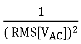
- Wherein, A denotes a loop output voltage that changes with the load, B denotes

- Accordingly, IL is in phase with VAC.
- In additional, Ixcap may be calculated by using Equation 3 below.

- Wherein, Cxcap denotes a capacitance of the X-cap,

-
FIG. 3 illustrates a schematic diagram of a composite input waveform without X-cap compensation. As illustrated inFIG. 3 , IAC is ahead of VAC due to the effect of Ixcap, which would result in a poor power factor.
- Wherein, cosθ denotes a phase shift power factor,

- In order to enable IAc to be in phase with the voltage input VAC of the AC power supply, IL may be modified to achieve a unit power factor. As mentioned above, a PFC current


- Wherein

-
FIG. 4 illustrates a schematic diagram of a composite input waveform with X-cap compensation. The results after performing the X-cap compensation are illustrated inFIG. 4 . As illustrated inFIG. 4 , composite IAC is in phase with VAC and a power factor is close to 1. - It thus can be known from the above that a key factor to implement the X-cap compensation is to generate, within the microcontroller unit, a reactive current flowing through the X-cap, that is, Ixcap (t). Certainly, the reactive current Ixcap (t) may also be detected by an isolated-type current meter, such as a Hall effect sensor. In the present disclosure, however, the reactive current Ixcap (t) is preferably obtained by an algorithm in the microcontroller unit.
- In this regard, in
Non-Patent Document 1, it is proposed to use a internal random access memory (RAM) to continuously record VAC to obtain cos(2πft). However, in the method given inNon-Patent Document 1, a large amount of RAM storage space is occupied, and it is proportional to a sampling rate in a half period of VAC. Moreover, if a line frequency is a time-varying variable, then it can be known from Equation 6 below that:

- To this end, the inventor of the present invention, after research, has proposed a new power factor correcting method. By using the method of the present disclosure to calculate the reference current, the reactive current of the EMI capacitor can be effectively compensated, and accordingly, the power factor can be improved and the current harmonic distortion can be reduced, and compared with the existing methods, code efficiency can be increased, and the microcontroller unit can generate a continuous reactive current of the EMI capacitor with less computing resources.
- The technical ideas and preferred embodiments of the present disclosure will be specifically described below.
- There is provided a power factor correcting method in the present disclosure. By applying the power factor correcting method of the present disclosure to a reference current calculation to compensate for the reactive current of an EMI capacitor, the power factor of a switching-type AC power supply can be improved, and the current harmonic distortion can be reduced.
-
FIG. 5 illustrates a flowchart of generating a new reference current using X-cap compensation according to an embodiment of the present disclosure. - In order to facilitate understanding of the present disclosure and avoid repetitive descriptions, a part of a current loop control flow is illustrated in
FIG. 5 , in which the calculation of Iref using Equation 2 is skipped. An output of the flowchart as illustrated inFIG. 5 is a new reference current
- As illustrated in
FIG. 5 , inStep 501, VAC zero-crossing points are digitally detected from a AC power supply (referring to theAC power supply 101 of the circuit illustrated inFIG. 1 and theAC power supply 201 of the circuit illustrated inFIG. 2 ), to obtain a period of VAC and set the period of VAC to T. InStep 502, the period T is used to generate a periodic function with half-wave symmetry, that is, a half-wave symmetric function f(t). Any type of periodic function may be generated inStep 502, as long as it has half-wave symmetry, such as square wave, triangular wave, trapezoidal wave, etc. The simpler the function is, the higher the code efficiency can be. For example, in this embodiment, the half-wave symmetric function f(t) may be generated using Equation 7 below, and the period of the half-wave symmetric function generated in this embodiment is equal to the period of VAC.
- Wherein T denotes the period of VAC.
- In
Step 503, a recursive filter y(t) is applied to the half-wave symmetric function f(t) to generate an approximately sine waveform. In this embodiment, the recursive filter y(t) is a low-pass filter. That is, the recursive low-pass filter y(t) is implemented using the half-wave symmetric function f(t). It should be noted that y(t) can be any type of recursive filter using one or more outputs as input. For example, Equation 9 as described in the following may be used to obtain the recursive filter y(t), by a simple replacement of τ(t) in Equation 9 with f(t). The characteristic of the recursive filter y(t) is to smooth the periodic function generated inStep 502 and is preferably capable of significantly attenuating relatively high frequency components after many VAC periods. In this embodiment, the obtained recursive filter y(t) can be represented as a sine wave with a baseline frequency, which looks like a reactive current Ixcap flowing through the X-cap, but may have different amplitudes and phase shifts. - In the present disclosure, when the amplitude and phase of the obtained recursive filter y(t) do not match the target Ixcap, a complex mathematical method may be used to calculate a gain and phase shift to adjust the amplitude and phase of y(t) so as to match the amplitude and phase shift of Ixcap.
- However, in this embodiment, steps 504, 505, 506, and 507 in
FIG. 5 are used to provide a preferred and simpler iterative method to adjust the amplitude and phase shift of y(t). - In this embodiment, in order to monitor y(t) and Iref, in
Step 506, the microcontroller unit MCU may derive y(t), as well as Iref (t) which is calculated from the voltage of the AC power supply and the loop output voltage using the above Equation 2, and verify whether the amplitude and phase of y(t) match the target Ixcap (t) calculated using the above Equation 3. If it is No inStep 506, then inStep 507, a gain is adjusted, and inStep 504, the adjusted gain is used as a multiplication coefficient to compensate for y(t) to adjust the amplitude of y(t). InStep 505, the phase of y(t) is adjusted to advance VAC by a given threshold. The amplitude and phase of y(t) can be approximately consistent with the target Ixcap (t) through several iterations. The given threshold is preferably in a range of 85 degrees to 95 degrees, and more preferably is 90 degrees. - Similar to the prior art using Equation 5 as described above, in this embodiment, a new reference current

steps FIG. 5 . Specifically, inStep 508, it is determined whether the target Iref (t) is greater than the absolute value of y(t). In this example, the comparison may be performed using the values of the target Iref (t) and y(t) at current time point. If it is YES inStep 508, then as shown inStep 509, the reference current
Step 506. If it is NO inStep 508, then it is determined inStep 510 whether the target Iref (t) is less than an absolute value of y(t). If it is NO inStep 510, then as shown inStep 511, the reference current
Step 510, then the current control cycle is repeated to update
- Further, in the present disclosure, after optimizing the gain and phase shift to obtain a proper power factor and lower current harmonic distortion (iTHD), steps 504, 505, 506, and 507 in
FIG. 5 may be omitted. - In addition, in order to support an entire range of the AC input, several sets of gains and phase shifts may be applied discretely based on the line frequency and amplitude (e.g., 230Vac at 50Hz or 110AC at 60Hz).
- Further, in the embodiments of the present disclosure, the half-wave symmetric periodic function f(t) may include, but not limited to, a square wave, a triangular wave, a trapezoidal wave, or the like. The digital low-pass filter y(t) may include, but not limited to, a recursive or non-recursive filter.
- Next, a specific embodiment of the present disclosure will be described.
-
FIG. 6 schematically illustrates a diagram of a detailed graphical description of X-cap compensation according to an embodiment of the present disclosure. In this embodiment, a triangular wave τ(t) is generated as an example of the half-wave symmetric periodic function f(t) in the above-mentioned embodiments. For a mathematical expression of the triangular wave τ(t), it may be expressed as a trigonometric function τ(t) as shown in Equation 8 below:
- Wherein τ(t) is in a range from -1 to +1. p is a periodic time of a period preceding VAC and is reset and updated at the end of the VAC period.
- In this embodiment, in order to use the microcontroller unit MCU more conveniently, the same input and output as those in Equation 8 are used to generate a triangular wave.
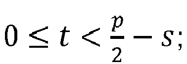
- First, zero-crossing points of VAC are detected to obtain the period of VAC. To adjust the phase, an instantaneous value of the trigonometric function τ(t) is reset to

symbol 603 inFIG. 6 . An upper limit (shown by thesymbol 601 inFIG. 6 ) of the value of the trigonometric function τ(t) is set to
symbol 602 inFIG. 6 ) of the value of the trigonometric function τ(t) is set to (the upper limit -



- Next, in this embodiment, a simple recursive low-pass filter R(t) can be obtained by using Equation 9 below. R(t) is an example of y(t) in the above embodiment.

- Wherein n is a natural number and A is a given gain.
- In this embodiment, R(t) may be any type of digital recursive low-pass filter, which corresponds to y(t) in the above embodiment.
- Next, the obtained recursive low-pass filter R(t) is applied to τ(t). If Iref (t) > |R(t)|, then


- Iref (t) and R(t) are derived to verify whether R(t) matches the amplitude and phase of the calculated target Ixcap (t).
- After several iterations, an appropriate amplitude (shown by the
symbol 605 inFIG. 6 ), phase (shown by thesymbol 604 inFIG. 6 ), and n in Equation 9 can be obtained. In this embodiment, R(t) should be close to the calculated target Ixcap (t). - If the above embodiments are applied to a 1600 watt AC-DC power supply unit of a 230Vac, 50Hz line, then result measurements of iTHD and power factor may be shown in Table 1 below.
[Table 1] Load ratio Before After iTHD Power factor iTHD Power factor 10 15.6 0.86 8.5 0.991 20 9.3 0.93 7.1 0.992 50 5.7 0.97 4.4 0.997 100 4.2 0.98 3.5 0.999 - Table 1 shows results before and after implementing the above embodiments at different percentages of full load. It can be seen from Table 1 that significant improvements can be obtained after the implementation of the above embodiments, especially at light loads, since the X-cap current is dominant.
- By applying the present disclosure, compared with the prior art methods, iTHD and power factor can be improved equivalently to or better than the prior art. In addition, compared with the prior art methods, which require more RAM and computing resources, the method of the present disclosure can improve code efficiency, and can compensate for the reactive current of the EMI capacitor by the microcontroller unit MCU with less computing resources. For example, if 2000 updates occur in one AC period, then compared with the prior art methods, the method of the present disclosure can save about 90% of RAM and 80% of computing time.
- In addition, the algorithm in the present disclosure can be implemented by, for example but not limited to, a microcontroller unit MCU, a digital signal processor, a processor, an object, an executable program, an execution thread, a program, and/or a computer.
Claims (13)
- A power factor correcting method for correcting a power factor of an alternating current (AC) power supply, comprising:detecting zero-crossing points of an input voltage VAC of the AC power supply to obtain a period T of the VAC;generating a half-wave symmetric periodic function f(t) by using the period T;implementing a recursive low-pass filter y(t) by using the f(t), so that an output of the y(t) matches a target reactive current Ixcap(t) flowing through an X-capacitor;generating a reference current
 correcting the power factor by using the reference current
- The power factor correcting method according to claim 1, wherein an output of the f(t) is a square wave, a triangular wave or a trapezoidal wave.
- The power factor correcting method according to claim 1, wherein the f(t) is generated by using the following equation:

- The power factor correcting method according to claim 1, wherein the f(t) is generated by using the following equation:

- The power factor correcting method according to any one of claims 1-4, wherein an amplitude and a phase of the y(t) match the Ixcap(t).
- The power factor correcting method according to any one of claims 1-4, further comprising: adjusting an amplitude and a phase of the y(t), so that the amplitude and the phase of the y(t) match the Ixcap(t).
- The power factor correcting method according to claim 6, wherein adjusting an amplitude and a phase of the y(t), so that the amplitude and the phase of the y(t) match the Ixcap(t) comprises:adjusting a gain;re-implementing the y(t) by using the adjusted gain and the f(t);adjusting the phase of the y(t) to advance the VAC by a given threshold; anddetermining whether the amplitude and the phase of the y(t) match the Ixcap(t).
- The power factor correcting method according to claim 7, wherein the given threshold is in a range of 85 degrees to 95 degrees.
- The power factor correcting method according to claim 7, wherein the given threshold is 90 degrees.
- The power factor correcting method according to any one of claims 1-4, wherein the y(t) is implemented by the following equation:

- The power factor correcting method according to any one of claims 1-4, wherein the target reactive current Ixcap(t) is calculated by the following equation:


- The power factor correcting method according to any one of claims 1-4, wherein:when the given reference current Iref (t) is greater than an absolute value of the y(t), the

 when the given reference current Iref (t) is equal to the absolute value of the y(t), the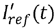
- The power factor correcting method according to any one of claims 1-4, wherein the given reference current Iref (t) is calculated based on a loop output voltage,
Applications Claiming Priority (1)
| Application Number | Priority Date | Filing Date | Title |
|---|---|---|---|
| CN201910256425.1A CN111756227B (en) | 2019-03-29 | 2019-03-29 | Power factor correction method |
Publications (2)
| Publication Number | Publication Date |
|---|---|
| EP3716459A1 true EP3716459A1 (en) | 2020-09-30 |
| EP3716459B1 EP3716459B1 (en) | 2022-09-14 |
Family
ID=69844722
Family Applications (1)
| Application Number | Title | Priority Date | Filing Date |
|---|---|---|---|
| EP20163394.8A Active EP3716459B1 (en) | 2019-03-29 | 2020-03-16 | Power factor correcting method |
Country Status (3)
| Country | Link |
|---|---|
| US (1) | US11068005B2 (en) |
| EP (1) | EP3716459B1 (en) |
| CN (1) | CN111756227B (en) |
Families Citing this family (2)
| Publication number | Priority date | Publication date | Assignee | Title |
|---|---|---|---|---|
| EP4111581B1 (en) | 2020-02-28 | 2025-08-06 | Astec International Limited | Power measurements in switched mode power supplies |
| KR20230045335A (en) * | 2021-09-28 | 2023-04-04 | 현대자동차주식회사 | Apparatus and method for controlling power factor correction |
Citations (3)
| Publication number | Priority date | Publication date | Assignee | Title |
|---|---|---|---|---|
| WO2002023694A2 (en) * | 2000-09-15 | 2002-03-21 | Artesyn Technologies, Inc. | Power factor correction control circuit and power supply including same |
| US20140052394A1 (en) * | 2012-08-20 | 2014-02-20 | Texas Instruments Incorporated | Systems and Methods of Input Power and Current Measurement |
| US20180278150A1 (en) * | 2017-03-22 | 2018-09-27 | Silergy Semiconductor Technology (Hangzhou) Ltd | Power factor correction circuit, control method and controller |
Family Cites Families (8)
| Publication number | Priority date | Publication date | Assignee | Title |
|---|---|---|---|---|
| KR100936432B1 (en) * | 2008-02-01 | 2010-01-12 | 명지대학교 산학협력단 | Digital Controller of Single Phase Active Power Filter and Its Control Method |
| US8723498B2 (en) * | 2008-12-19 | 2014-05-13 | Hewlett-Packard Development Company, L.P. | Systems and methods of increasing power measurement accuracy for power factor correction |
| US8874277B2 (en) * | 2009-09-15 | 2014-10-28 | Denis Kouroussis | Smart-grid adaptive power management method and system with power factor optimization and total harmonic distortion reduction |
| WO2012014086A2 (en) * | 2010-07-28 | 2012-02-02 | Marvell World Trade Ltd. | Method and apparatus for wave detection |
| US8872484B2 (en) | 2011-08-17 | 2014-10-28 | Google Inc. | Power factor correction circuitry and methodology to compensate for leading power factor |
| DE102012111853B4 (en) * | 2011-12-06 | 2014-04-24 | Exscitron Gmbh | Switching power supply device and use of such |
| DE102012018495B3 (en) * | 2012-09-17 | 2013-12-19 | Vermot AG | Method of compensating for inductive reactive current and reactive power of electrical load involves operating detector circuits such that switching time dot takes place precisely in zero crossover of voltage/current to neutral |
| CN107370358B (en) * | 2016-05-13 | 2021-03-02 | 伊顿制造(格拉斯哥)有限合伙莫尔日分支机构 | Current loop control method of power factor correction circuit and current loop controller |
-
2019
- 2019-03-29 CN CN201910256425.1A patent/CN111756227B/en active Active
-
2020
- 2020-03-16 EP EP20163394.8A patent/EP3716459B1/en active Active
- 2020-03-23 US US16/826,710 patent/US11068005B2/en active Active
Patent Citations (3)
| Publication number | Priority date | Publication date | Assignee | Title |
|---|---|---|---|---|
| WO2002023694A2 (en) * | 2000-09-15 | 2002-03-21 | Artesyn Technologies, Inc. | Power factor correction control circuit and power supply including same |
| US20140052394A1 (en) * | 2012-08-20 | 2014-02-20 | Texas Instruments Incorporated | Systems and Methods of Input Power and Current Measurement |
| US20180278150A1 (en) * | 2017-03-22 | 2018-09-27 | Silergy Semiconductor Technology (Hangzhou) Ltd | Power factor correction circuit, control method and controller |
Non-Patent Citations (1)
| Title |
|---|
| BOSHENG SUN: "Increase power factor by digitally compensating for PFC EMI-capacitor reactive current", 31 December 2016 (2016-12-31), XP055717557, Retrieved from the Internet <URL:https://www.ti.com/lit/an/slyt673/slyt673.pdf> [retrieved on 20200723] * |
Also Published As
| Publication number | Publication date |
|---|---|
| CN111756227B (en) | 2024-07-05 |
| CN111756227A (en) | 2020-10-09 |
| US11068005B2 (en) | 2021-07-20 |
| EP3716459B1 (en) | 2022-09-14 |
| US20200313546A1 (en) | 2020-10-01 |
Similar Documents
| Publication | Publication Date | Title |
|---|---|---|
| TWI551018B (en) | Power factor correction conversion device and control method thereof | |
| CN111954916B (en) | Adaptive control for power generator | |
| TWI657649B (en) | Power factor correction circuit, control method and controller | |
| CN113315126B (en) | Specified subharmonic suppression secondary sampling method and system for active power filter | |
| US20110292699A1 (en) | Systems and Methods for Distortion Reduction | |
| EP3716459B1 (en) | Power factor correcting method | |
| TWI765245B (en) | Power factor correction circuit, control method and controller | |
| CN107370358B (en) | Current loop control method of power factor correction circuit and current loop controller | |
| CN107394780B (en) | Resonance current suppression method of LCL type grid-connected inverter capacitor-free current sensor | |
| CN112366965A (en) | Adaptive prediction and zero-pole compensation combined control method for inverter delay | |
| CN110661263B (en) | Frequency-locked loop with adaptive delay filter and control method of grid-connected inverter based on the frequency-locked loop | |
| CN108964055A (en) | A kind of voltage feed-forward control control method of capacitor current feedback | |
| Naqvi et al. | An enhanced filtering generalized integrator-based control for improved performance of a grid-tied PV system at adverse grid voltages | |
| KR100936432B1 (en) | Digital Controller of Single Phase Active Power Filter and Its Control Method | |
| Kessal et al. | Analysis and design of an isolated single-phase power factor corrector with a fast regulation | |
| US11824440B2 (en) | Power converter power factor control | |
| US20220399806A1 (en) | Power converter power factor control | |
| Cabezas et al. | Comparison and combination of digital controls for single-phase boost PFC converters in avionic power systems | |
| Townsend et al. | Comparison of modulation strategies for a cascaded H-bridge StatCom—Part 1: Theoretical background | |
| Ranjan et al. | Cimmcc and mstogi based solar pv system for improvement in power quality under grid voltage variation | |
| Laggoun et al. | Dual Virtual Flux-based Direct Power Control for rectifier under harmonically distorted voltage condition | |
| CN111130113A (en) | Method and system for determining compensation current of active power filter | |
| Liao et al. | A PLL‐Less Grid Voltage Sensorless Improved Deadbeat Control for APF With LVRT Capability | |
| JP2000152504A (en) | Reactive power compensating device | |
| Lamo et al. | Implementation Oriented Two-Sample Phase Locked Loop for Single-Phase PFCs |
Legal Events
| Date | Code | Title | Description |
|---|---|---|---|
| PUAI | Public reference made under article 153(3) epc to a published international application that has entered the european phase |
Free format text: ORIGINAL CODE: 0009012 |
|
| STAA | Information on the status of an ep patent application or granted ep patent |
Free format text: STATUS: THE APPLICATION HAS BEEN PUBLISHED |
|
| AK | Designated contracting states |
Kind code of ref document: A1 Designated state(s): AL AT BE BG CH CY CZ DE DK EE ES FI FR GB GR HR HU IE IS IT LI LT LU LV MC MK MT NL NO PL PT RO RS SE SI SK SM TR |
|
| AX | Request for extension of the european patent |
Extension state: BA ME |
|
| STAA | Information on the status of an ep patent application or granted ep patent |
Free format text: STATUS: REQUEST FOR EXAMINATION WAS MADE |
|
| 17P | Request for examination filed |
Effective date: 20210210 |
|
| REG | Reference to a national code |
Ref country code: DE Ref legal event code: R079 Ref document number: 602020005062 Country of ref document: DE Free format text: PREVIOUS MAIN CLASS: H02M0001420000 Ipc: G01R0021000000 |
|
| RIC1 | Information provided on ipc code assigned before grant |
Ipc: G01R 21/133 20060101ALI20220228BHEP Ipc: H02M 1/42 20070101ALI20220228BHEP Ipc: G01R 21/00 20060101AFI20220228BHEP |
|
| GRAP | Despatch of communication of intention to grant a patent |
Free format text: ORIGINAL CODE: EPIDOSNIGR1 |
|
| STAA | Information on the status of an ep patent application or granted ep patent |
Free format text: STATUS: GRANT OF PATENT IS INTENDED |
|
| INTG | Intention to grant announced |
Effective date: 20220411 |
|
| GRAS | Grant fee paid |
Free format text: ORIGINAL CODE: EPIDOSNIGR3 |
|
| GRAA | (expected) grant |
Free format text: ORIGINAL CODE: 0009210 |
|
| STAA | Information on the status of an ep patent application or granted ep patent |
Free format text: STATUS: THE PATENT HAS BEEN GRANTED |
|
| AK | Designated contracting states |
Kind code of ref document: B1 Designated state(s): AL AT BE BG CH CY CZ DE DK EE ES FI FR GB GR HR HU IE IS IT LI LT LU LV MC MK MT NL NO PL PT RO RS SE SI SK SM TR |
|
| REG | Reference to a national code |
Ref country code: GB Ref legal event code: FG4D |
|
| REG | Reference to a national code |
Ref country code: CH Ref legal event code: EP |
|
| REG | Reference to a national code |
Ref country code: DE Ref legal event code: R096 Ref document number: 602020005062 Country of ref document: DE |
|
| REG | Reference to a national code |
Ref country code: IE Ref legal event code: FG4D |
|
| REG | Reference to a national code |
Ref country code: AT Ref legal event code: REF Ref document number: 1519014 Country of ref document: AT Kind code of ref document: T Effective date: 20221015 |
|
| REG | Reference to a national code |
Ref country code: LT Ref legal event code: MG9D |
|
| REG | Reference to a national code |
Ref country code: NL Ref legal event code: MP Effective date: 20220914 |
|
| PG25 | Lapsed in a contracting state [announced via postgrant information from national office to epo] |
Ref country code: SE Free format text: LAPSE BECAUSE OF FAILURE TO SUBMIT A TRANSLATION OF THE DESCRIPTION OR TO PAY THE FEE WITHIN THE PRESCRIBED TIME-LIMIT Effective date: 20220914 Ref country code: RS Free format text: LAPSE BECAUSE OF FAILURE TO SUBMIT A TRANSLATION OF THE DESCRIPTION OR TO PAY THE FEE WITHIN THE PRESCRIBED TIME-LIMIT Effective date: 20220914 Ref country code: NO Free format text: LAPSE BECAUSE OF FAILURE TO SUBMIT A TRANSLATION OF THE DESCRIPTION OR TO PAY THE FEE WITHIN THE PRESCRIBED TIME-LIMIT Effective date: 20221214 Ref country code: LV Free format text: LAPSE BECAUSE OF FAILURE TO SUBMIT A TRANSLATION OF THE DESCRIPTION OR TO PAY THE FEE WITHIN THE PRESCRIBED TIME-LIMIT Effective date: 20220914 Ref country code: LT Free format text: LAPSE BECAUSE OF FAILURE TO SUBMIT A TRANSLATION OF THE DESCRIPTION OR TO PAY THE FEE WITHIN THE PRESCRIBED TIME-LIMIT Effective date: 20220914 Ref country code: FI Free format text: LAPSE BECAUSE OF FAILURE TO SUBMIT A TRANSLATION OF THE DESCRIPTION OR TO PAY THE FEE WITHIN THE PRESCRIBED TIME-LIMIT Effective date: 20220914 |
|
| REG | Reference to a national code |
Ref country code: AT Ref legal event code: MK05 Ref document number: 1519014 Country of ref document: AT Kind code of ref document: T Effective date: 20220914 |
|
| PG25 | Lapsed in a contracting state [announced via postgrant information from national office to epo] |
Ref country code: HR Free format text: LAPSE BECAUSE OF FAILURE TO SUBMIT A TRANSLATION OF THE DESCRIPTION OR TO PAY THE FEE WITHIN THE PRESCRIBED TIME-LIMIT Effective date: 20220914 Ref country code: GR Free format text: LAPSE BECAUSE OF FAILURE TO SUBMIT A TRANSLATION OF THE DESCRIPTION OR TO PAY THE FEE WITHIN THE PRESCRIBED TIME-LIMIT Effective date: 20221215 |
|
| PG25 | Lapsed in a contracting state [announced via postgrant information from national office to epo] |
Ref country code: SM Free format text: LAPSE BECAUSE OF FAILURE TO SUBMIT A TRANSLATION OF THE DESCRIPTION OR TO PAY THE FEE WITHIN THE PRESCRIBED TIME-LIMIT Effective date: 20220914 Ref country code: RO Free format text: LAPSE BECAUSE OF FAILURE TO SUBMIT A TRANSLATION OF THE DESCRIPTION OR TO PAY THE FEE WITHIN THE PRESCRIBED TIME-LIMIT Effective date: 20220914 Ref country code: PT Free format text: LAPSE BECAUSE OF FAILURE TO SUBMIT A TRANSLATION OF THE DESCRIPTION OR TO PAY THE FEE WITHIN THE PRESCRIBED TIME-LIMIT Effective date: 20230116 Ref country code: ES Free format text: LAPSE BECAUSE OF FAILURE TO SUBMIT A TRANSLATION OF THE DESCRIPTION OR TO PAY THE FEE WITHIN THE PRESCRIBED TIME-LIMIT Effective date: 20220914 Ref country code: CZ Free format text: LAPSE BECAUSE OF FAILURE TO SUBMIT A TRANSLATION OF THE DESCRIPTION OR TO PAY THE FEE WITHIN THE PRESCRIBED TIME-LIMIT Effective date: 20220914 Ref country code: AT Free format text: LAPSE BECAUSE OF FAILURE TO SUBMIT A TRANSLATION OF THE DESCRIPTION OR TO PAY THE FEE WITHIN THE PRESCRIBED TIME-LIMIT Effective date: 20220914 |
|
| PG25 | Lapsed in a contracting state [announced via postgrant information from national office to epo] |
Ref country code: SK Free format text: LAPSE BECAUSE OF FAILURE TO SUBMIT A TRANSLATION OF THE DESCRIPTION OR TO PAY THE FEE WITHIN THE PRESCRIBED TIME-LIMIT Effective date: 20220914 Ref country code: PL Free format text: LAPSE BECAUSE OF FAILURE TO SUBMIT A TRANSLATION OF THE DESCRIPTION OR TO PAY THE FEE WITHIN THE PRESCRIBED TIME-LIMIT Effective date: 20220914 Ref country code: IS Free format text: LAPSE BECAUSE OF FAILURE TO SUBMIT A TRANSLATION OF THE DESCRIPTION OR TO PAY THE FEE WITHIN THE PRESCRIBED TIME-LIMIT Effective date: 20230114 Ref country code: EE Free format text: LAPSE BECAUSE OF FAILURE TO SUBMIT A TRANSLATION OF THE DESCRIPTION OR TO PAY THE FEE WITHIN THE PRESCRIBED TIME-LIMIT Effective date: 20220914 |
|
| REG | Reference to a national code |
Ref country code: DE Ref legal event code: R097 Ref document number: 602020005062 Country of ref document: DE |
|
| PG25 | Lapsed in a contracting state [announced via postgrant information from national office to epo] |
Ref country code: NL Free format text: LAPSE BECAUSE OF FAILURE TO SUBMIT A TRANSLATION OF THE DESCRIPTION OR TO PAY THE FEE WITHIN THE PRESCRIBED TIME-LIMIT Effective date: 20220914 Ref country code: AL Free format text: LAPSE BECAUSE OF FAILURE TO SUBMIT A TRANSLATION OF THE DESCRIPTION OR TO PAY THE FEE WITHIN THE PRESCRIBED TIME-LIMIT Effective date: 20220914 |
|
| PLBE | No opposition filed within time limit |
Free format text: ORIGINAL CODE: 0009261 |
|
| STAA | Information on the status of an ep patent application or granted ep patent |
Free format text: STATUS: NO OPPOSITION FILED WITHIN TIME LIMIT |
|
| PG25 | Lapsed in a contracting state [announced via postgrant information from national office to epo] |
Ref country code: DK Free format text: LAPSE BECAUSE OF FAILURE TO SUBMIT A TRANSLATION OF THE DESCRIPTION OR TO PAY THE FEE WITHIN THE PRESCRIBED TIME-LIMIT Effective date: 20220914 |
|
| 26N | No opposition filed |
Effective date: 20230615 |
|
| PG25 | Lapsed in a contracting state [announced via postgrant information from national office to epo] |
Ref country code: SI Free format text: LAPSE BECAUSE OF FAILURE TO SUBMIT A TRANSLATION OF THE DESCRIPTION OR TO PAY THE FEE WITHIN THE PRESCRIBED TIME-LIMIT Effective date: 20220914 |
|
| PG25 | Lapsed in a contracting state [announced via postgrant information from national office to epo] |
Ref country code: MC Free format text: LAPSE BECAUSE OF FAILURE TO SUBMIT A TRANSLATION OF THE DESCRIPTION OR TO PAY THE FEE WITHIN THE PRESCRIBED TIME-LIMIT Effective date: 20220914 |
|
| REG | Reference to a national code |
Ref country code: CH Ref legal event code: PL |
|
| REG | Reference to a national code |
Ref country code: BE Ref legal event code: MM Effective date: 20230331 |
|
| PG25 | Lapsed in a contracting state [announced via postgrant information from national office to epo] |
Ref country code: LU Free format text: LAPSE BECAUSE OF NON-PAYMENT OF DUE FEES Effective date: 20230316 |
|
| REG | Reference to a national code |
Ref country code: IE Ref legal event code: MM4A |
|
| PG25 | Lapsed in a contracting state [announced via postgrant information from national office to epo] |
Ref country code: LI Free format text: LAPSE BECAUSE OF NON-PAYMENT OF DUE FEES Effective date: 20230331 Ref country code: IE Free format text: LAPSE BECAUSE OF NON-PAYMENT OF DUE FEES Effective date: 20230316 Ref country code: FR Free format text: LAPSE BECAUSE OF NON-PAYMENT OF DUE FEES Effective date: 20230331 Ref country code: CH Free format text: LAPSE BECAUSE OF NON-PAYMENT OF DUE FEES Effective date: 20230331 |
|
| PG25 | Lapsed in a contracting state [announced via postgrant information from national office to epo] |
Ref country code: BE Free format text: LAPSE BECAUSE OF NON-PAYMENT OF DUE FEES Effective date: 20230331 |
|
| PG25 | Lapsed in a contracting state [announced via postgrant information from national office to epo] |
Ref country code: IT Free format text: LAPSE BECAUSE OF FAILURE TO SUBMIT A TRANSLATION OF THE DESCRIPTION OR TO PAY THE FEE WITHIN THE PRESCRIBED TIME-LIMIT Effective date: 20220914 |
|
| PG25 | Lapsed in a contracting state [announced via postgrant information from national office to epo] |
Ref country code: BG Free format text: LAPSE BECAUSE OF FAILURE TO SUBMIT A TRANSLATION OF THE DESCRIPTION OR TO PAY THE FEE WITHIN THE PRESCRIBED TIME-LIMIT Effective date: 20220914 |
|
| GBPC | Gb: european patent ceased through non-payment of renewal fee |
Effective date: 20240316 |
|
| PG25 | Lapsed in a contracting state [announced via postgrant information from national office to epo] |
Ref country code: BG Free format text: LAPSE BECAUSE OF FAILURE TO SUBMIT A TRANSLATION OF THE DESCRIPTION OR TO PAY THE FEE WITHIN THE PRESCRIBED TIME-LIMIT Effective date: 20220914 |
|
| PG25 | Lapsed in a contracting state [announced via postgrant information from national office to epo] |
Ref country code: GB Free format text: LAPSE BECAUSE OF NON-PAYMENT OF DUE FEES Effective date: 20240316 |
|
| PG25 | Lapsed in a contracting state [announced via postgrant information from national office to epo] |
Ref country code: GB Free format text: LAPSE BECAUSE OF NON-PAYMENT OF DUE FEES Effective date: 20240316 |
|
| PG25 | Lapsed in a contracting state [announced via postgrant information from national office to epo] |
Ref country code: CY Free format text: LAPSE BECAUSE OF FAILURE TO SUBMIT A TRANSLATION OF THE DESCRIPTION OR TO PAY THE FEE WITHIN THE PRESCRIBED TIME-LIMIT; INVALID AB INITIO Effective date: 20200316 |
|
| PG25 | Lapsed in a contracting state [announced via postgrant information from national office to epo] |
Ref country code: HU Free format text: LAPSE BECAUSE OF FAILURE TO SUBMIT A TRANSLATION OF THE DESCRIPTION OR TO PAY THE FEE WITHIN THE PRESCRIBED TIME-LIMIT; INVALID AB INITIO Effective date: 20200316 |
|
| PG25 | Lapsed in a contracting state [announced via postgrant information from national office to epo] |
Ref country code: TR Free format text: LAPSE BECAUSE OF FAILURE TO SUBMIT A TRANSLATION OF THE DESCRIPTION OR TO PAY THE FEE WITHIN THE PRESCRIBED TIME-LIMIT Effective date: 20220914 |
|
| PGFP | Annual fee paid to national office [announced via postgrant information from national office to epo] |
Ref country code: DE Payment date: 20260319 Year of fee payment: 7 |