EP3716394B1 - Electricity storage device and railroad car - Google Patents
Electricity storage device and railroad car Download PDFInfo
- Publication number
- EP3716394B1 EP3716394B1 EP18880785.3A EP18880785A EP3716394B1 EP 3716394 B1 EP3716394 B1 EP 3716394B1 EP 18880785 A EP18880785 A EP 18880785A EP 3716394 B1 EP3716394 B1 EP 3716394B1
- Authority
- EP
- European Patent Office
- Prior art keywords
- box
- storage device
- opening
- side plate
- electricity storage
- Prior art date
- Legal status (The legal status is an assumption and is not a legal conclusion. Google has not performed a legal analysis and makes no representation as to the accuracy of the status listed.)
- Active
Links
Images




Classifications
-
- B—PERFORMING OPERATIONS; TRANSPORTING
- B61—RAILWAYS
- B61C—LOCOMOTIVES; MOTOR RAILCARS
- B61C17/00—Arrangement or disposition of parts; Details or accessories not otherwise provided for; Use of control gear and control systems
-
- H—ELECTRICITY
- H01—ELECTRIC ELEMENTS
- H01M—PROCESSES OR MEANS, e.g. BATTERIES, FOR THE DIRECT CONVERSION OF CHEMICAL ENERGY INTO ELECTRICAL ENERGY
- H01M10/00—Secondary cells; Manufacture thereof
- H01M10/60—Heating or cooling; Temperature control
- H01M10/62—Heating or cooling; Temperature control specially adapted for specific applications
- H01M10/625—Vehicles
-
- B—PERFORMING OPERATIONS; TRANSPORTING
- B61—RAILWAYS
- B61C—LOCOMOTIVES; MOTOR RAILCARS
- B61C3/00—Electric locomotives or railcars
- B61C3/02—Electric locomotives or railcars with electric accumulators
-
- H—ELECTRICITY
- H01—ELECTRIC ELEMENTS
- H01M—PROCESSES OR MEANS, e.g. BATTERIES, FOR THE DIRECT CONVERSION OF CHEMICAL ENERGY INTO ELECTRICAL ENERGY
- H01M10/00—Secondary cells; Manufacture thereof
- H01M10/60—Heating or cooling; Temperature control
- H01M10/61—Types of temperature control
- H01M10/613—Cooling or keeping cold
-
- H—ELECTRICITY
- H01—ELECTRIC ELEMENTS
- H01M—PROCESSES OR MEANS, e.g. BATTERIES, FOR THE DIRECT CONVERSION OF CHEMICAL ENERGY INTO ELECTRICAL ENERGY
- H01M10/00—Secondary cells; Manufacture thereof
- H01M10/60—Heating or cooling; Temperature control
- H01M10/65—Means for temperature control structurally associated with the cells
- H01M10/655—Solid structures for heat exchange or heat conduction
- H01M10/6551—Surfaces specially adapted for heat dissipation or radiation, e.g. fins or coatings
-
- H—ELECTRICITY
- H01—ELECTRIC ELEMENTS
- H01M—PROCESSES OR MEANS, e.g. BATTERIES, FOR THE DIRECT CONVERSION OF CHEMICAL ENERGY INTO ELECTRICAL ENERGY
- H01M10/00—Secondary cells; Manufacture thereof
- H01M10/60—Heating or cooling; Temperature control
- H01M10/65—Means for temperature control structurally associated with the cells
- H01M10/655—Solid structures for heat exchange or heat conduction
- H01M10/6554—Rods or plates
-
- H—ELECTRICITY
- H01—ELECTRIC ELEMENTS
- H01M—PROCESSES OR MEANS, e.g. BATTERIES, FOR THE DIRECT CONVERSION OF CHEMICAL ENERGY INTO ELECTRICAL ENERGY
- H01M10/00—Secondary cells; Manufacture thereof
- H01M10/60—Heating or cooling; Temperature control
- H01M10/65—Means for temperature control structurally associated with the cells
- H01M10/655—Solid structures for heat exchange or heat conduction
- H01M10/6556—Solid parts with flow channel passages or pipes for heat exchange
-
- H—ELECTRICITY
- H01—ELECTRIC ELEMENTS
- H01M—PROCESSES OR MEANS, e.g. BATTERIES, FOR THE DIRECT CONVERSION OF CHEMICAL ENERGY INTO ELECTRICAL ENERGY
- H01M10/00—Secondary cells; Manufacture thereof
- H01M10/60—Heating or cooling; Temperature control
- H01M10/65—Means for temperature control structurally associated with the cells
- H01M10/656—Means for temperature control structurally associated with the cells characterised by the type of heat-exchange fluid
- H01M10/6561—Gases
- H01M10/6562—Gases with free flow by convection only
-
- H—ELECTRICITY
- H01—ELECTRIC ELEMENTS
- H01M—PROCESSES OR MEANS, e.g. BATTERIES, FOR THE DIRECT CONVERSION OF CHEMICAL ENERGY INTO ELECTRICAL ENERGY
- H01M50/00—Constructional details or processes of manufacture of the non-active parts of electrochemical cells other than fuel cells, e.g. hybrid cells
- H01M50/20—Mountings; Secondary casings or frames; Racks, modules or packs; Suspension devices; Shock absorbers; Transport or carrying devices; Holders
- H01M50/204—Racks, modules or packs for multiple batteries or multiple cells
-
- H—ELECTRICITY
- H01—ELECTRIC ELEMENTS
- H01M—PROCESSES OR MEANS, e.g. BATTERIES, FOR THE DIRECT CONVERSION OF CHEMICAL ENERGY INTO ELECTRICAL ENERGY
- H01M50/00—Constructional details or processes of manufacture of the non-active parts of electrochemical cells other than fuel cells, e.g. hybrid cells
- H01M50/20—Mountings; Secondary casings or frames; Racks, modules or packs; Suspension devices; Shock absorbers; Transport or carrying devices; Holders
- H01M50/249—Mountings; Secondary casings or frames; Racks, modules or packs; Suspension devices; Shock absorbers; Transport or carrying devices; Holders specially adapted for aircraft or vehicles, e.g. cars or trains
-
- B—PERFORMING OPERATIONS; TRANSPORTING
- B60—VEHICLES IN GENERAL
- B60L—PROPULSION OF ELECTRICALLY-PROPELLED VEHICLES; SUPPLYING ELECTRIC POWER FOR AUXILIARY EQUIPMENT OF ELECTRICALLY-PROPELLED VEHICLES; ELECTRODYNAMIC BRAKE SYSTEMS FOR VEHICLES IN GENERAL; MAGNETIC SUSPENSION OR LEVITATION FOR VEHICLES; MONITORING OPERATING VARIABLES OF ELECTRICALLY-PROPELLED VEHICLES; ELECTRIC SAFETY DEVICES FOR ELECTRICALLY-PROPELLED VEHICLES
- B60L5/00—Current collectors for power supply lines of electrically-propelled vehicles
-
- H—ELECTRICITY
- H01—ELECTRIC ELEMENTS
- H01M—PROCESSES OR MEANS, e.g. BATTERIES, FOR THE DIRECT CONVERSION OF CHEMICAL ENERGY INTO ELECTRICAL ENERGY
- H01M2220/00—Batteries for particular applications
- H01M2220/20—Batteries in motive systems, e.g. vehicle, ship, plane
-
- Y—GENERAL TAGGING OF NEW TECHNOLOGICAL DEVELOPMENTS; GENERAL TAGGING OF CROSS-SECTIONAL TECHNOLOGIES SPANNING OVER SEVERAL SECTIONS OF THE IPC; TECHNICAL SUBJECTS COVERED BY FORMER USPC CROSS-REFERENCE ART COLLECTIONS [XRACs] AND DIGESTS
- Y02—TECHNOLOGIES OR APPLICATIONS FOR MITIGATION OR ADAPTATION AGAINST CLIMATE CHANGE
- Y02E—REDUCTION OF GREENHOUSE GAS [GHG] EMISSIONS, RELATED TO ENERGY GENERATION, TRANSMISSION OR DISTRIBUTION
- Y02E60/00—Enabling technologies; Technologies with a potential or indirect contribution to GHG emissions mitigation
- Y02E60/10—Energy storage using batteries
-
- Y—GENERAL TAGGING OF NEW TECHNOLOGICAL DEVELOPMENTS; GENERAL TAGGING OF CROSS-SECTIONAL TECHNOLOGIES SPANNING OVER SEVERAL SECTIONS OF THE IPC; TECHNICAL SUBJECTS COVERED BY FORMER USPC CROSS-REFERENCE ART COLLECTIONS [XRACs] AND DIGESTS
- Y02—TECHNOLOGIES OR APPLICATIONS FOR MITIGATION OR ADAPTATION AGAINST CLIMATE CHANGE
- Y02T—CLIMATE CHANGE MITIGATION TECHNOLOGIES RELATED TO TRANSPORTATION
- Y02T30/00—Transportation of goods or passengers via railways, e.g. energy recovery or reducing air resistance
Definitions
- Embodiments described herein relate generally to an electricity storage device and a railroad car.
- a railroad car receives supply of power from an overhead line or a power generation system mounted on the railroad car.
- a railroad car includes an electricity storage device as an emergency power supply for securing certain functions for a certain period of time when supply of power is cut off.
- electricity storage devices mounted on a railroad car have been used as an emergency power supply combined with a system for supplying power to a drive system.
- Battery modules are housed in an electricity storage device.
- a plurality of storage batteries in which electrodes and electrolytic solutions are housed are disposed inside the battery module.
- Conductors for connecting the storage batteries to each other and a control device of the storage batteries are also housed inside the battery module.
- Storage batteries generate heat. Therefore, cooling of storage batteries with a fan to release heat generated from the storage batteries to the outside of the electricity storage device has been studied.
- a failure detection function for detecting a failure of the fan needs to be provided and the fan needs to be replaced on a regular basis according to the service life. Also, since external air is forcibly taken into the electricity storage device using a fan, a filter for removing dust and foreign matter needs to be provided upstream of the fan. Therefore, the filter needs to be replaced on a regular basis.
- a problem to be solved by the present invention is to provide an electricity storage device and a railroad car in which storage batteries can be efficiently cooled without using a fan.
- An electricity storage device includes a first box, a second box, a storage battery, and a flow path.
- the second box includes a side plate and is housed in the first box.
- the storage battery is disposed in the second box while being connected to the side plate.
- the flow path is configured to include the side plate of the second box inside the first box and outside the second box and vertically penetrates the first box.
- FIGS. 1 to 7 a first embodiment of an electricity storage device of a railroad car will be described with reference to FIGS. 1 to 7 .
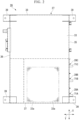
- an electricity storage device 26 of the present embodiment includes a first box 27, a plurality (three in the present embodiment) of battery modules 28, a protection circuit 29, and a control circuit 30. Further, the number of battery modules 28 included in the electricity storage device 26 is not limited, and may be one, two, or four or more.
- the electricity storage device 26 is mounted, for example, under a floor of a car body of the railroad car.
- the plurality of battery modules 28 are distinguished for indicating them individually, they are referred to as a battery module 28A, a battery module 28B, and a battery module 28C in order from the front toward the rear of the car body.
- the battery modules 28A, 28B, and 28C are collectively referred to as the battery module 28.
- reference numerals for the battery modules in the drawings are not denoted as 28 but denoted as 28A or the like. The same applies to an opening 42a, a receiving member 43, or the like to be described below.
- the first box 27 includes a first top plate 33, a first bottom plate 34, and first side plates 35 to 38.
- the first top plate 33, the first bottom plate 34, and the first side plates 35 to 38 are formed of a steel plate or the like.
- the first top plate 33 and the first bottom plate 34 are formed in a rectangular shape that is long in a longitudinal direction X (hereinafter, simply referred to as a longitudinal direction X) of the car body in plan view.
- the first top plate 33 and the first bottom plate 34 are disposed to face each other in a vertical direction.
- the first side plates 35 and 36 are provided to stand upright on outer edge portions in the longitudinal direction X of the first bottom plate 34.
- the first side plates 37 and 38 are provided to stand upright on outer edge portions of the first bottom plate 34 in a width direction Y (hereinafter, simply referred to as a width direction Y) of the car body.
- first side plate 36 side with respect to the first side plate 35 is referred to as a right side
- first side plate 35 side with respect to the first side plate 36 is referred to as a left side
- the first side plate 37 side with respect to the first side plate 38 is referred to as the front
- the first side plate 38 side with respect to the first side plate 37 is referred to as the rear.
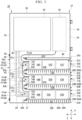
- a plurality of first through-holes 33a are formed in the front portion of the first top plate 33.
- the plurality of first through-holes 33a are disposed in a grid pattern.
- a mounting member 39 for fixing the first box 27 to the car body is fixed to each corner of the first top plate 33.
- the mounting member 39 protrudes upward with respect to the first top plate 33 of the first box 27.
- a plurality of first through-holes are formed in the first bottom plate 34 at a position facing the plurality of first through-holes 33a of the first top plate 33.
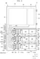
- an opening 35a is formed in the front portion of the first side plate 35.
- a first partition plate 40 extending to the right side is attached to an edge portion of the first side plate 35 behind the opening 35a.
- the first partition plate 40 extends to an intermediate portion between the first side plate 35 and the first side plate 36.
- an inspection cover 35b is provided in the rear portion of the first side plate 35.
- the inspection cover 35b is used for inspection work of the protection circuit 29 and the control circuit 30.
- a first partition plate (partition plate) 41 extending to the front is attached to a right end portion of the first partition plate 40.
- the first partition plates 40 and 41 are provided in the first box 27.
- the first partition plate 41 includes a plate main body 42 and a plurality of receiving members 43.
- the plate main body 42 extends to the front from the right end portion of the first partition plate 40 until reaching the first side plate 37.
- the plate main body 42 is joined to the first side plate 37 by welding or the like.
- the first partition plate 40 and the plate main body 42 extend to the first top plate 33 and the first bottom plate 34 and are joined to the first top plate 33 and the first bottom plate 34 by welding or the like.
- a plurality (three in the present embodiment) of openings 42aA, 42aB, and 42aC are formed in the plate main body 42.
- Each of the openings 42a is formed in a rectangular frame shape when viewed in the width direction Y.
- the plurality of openings 42aA, 42aB, and 42aC are disposed to be aligned in that order from the front to the rear in the longitudinal direction X with spaces therebetween.
- a receiving member 43A (one of the plurality of receiving members 43) described above is fixed to an edge portion of the opening 42aA in the plate main body 42.
- the receiving member 43A is formed in a rectangular frame shape when viewed in the width direction Y.
- the receiving member 43A protrudes toward a left side from the plate main body 42 over the entire circumference of the edge portion of the opening 42aA.
- the receiving member 43B is fixed to an edge portion of the opening 42aB
- the receiving member 43C is fixed to an edge portion of the opening 42aC.
- the opening 42aA of the plate main body 42 and the opening of the receiving member 43A constitute a first opening 41aA of the first partition plate 41.
- the opening 42aB of the plate main body 42 and the opening of the receiving member 43B constitute a first opening 41aB of the first partition plate 41.
- the opening 42aC of the plate main body 42 and the opening of the receiving member 43C constitute a first opening 41aC of the first partition plate 41.
- An opening 36a is formed in the front portion of the first side plate 36.
- the opening 36a of the first side plate 36 is covered with a work cover 45.
- the work cover 45 is detachably attached to the first side plate 36 by a fastening member 46 such as a bolt or a screw.
- the plurality of battery modules 28 include a battery module 28A, a battery module 28B, and a battery module 28C.
- a configuration of the battery module 28A and configurations of the battery modules 28B and 28C are the same as each other.
- the components of the battery module 28A are denoted by adding a capital letter "A” to a numeral, or a numeral and a lowercase letter.
- the components of the battery modules 28B and 28C corresponding to the battery module 28A are denoted by adding a capital letter "B” or "C” to the same numeral, or the same numeral and lowercase letter as in the battery module 28A. Therefore, duplicated description will be omitted.
- a second box 51A, to be described below, of the battery module 28A and second boxes 51B and 51C, to be described below, of the battery modules 28B and 28C have the same configuration as each other.
- the battery module 28A includes the second box 51A, a plurality (three in the present embodiment) of storage batteries 52A, 53A, and 54A, and a packing (sealing member) 55A.
- An external form of the second box 51A is formed in a rectangular parallelepiped box shape. A right side of the second box 51A opens to form a second opening 51aA in the second box 51A. The second box 51A is housed in the first box 27.
- the second box 51A includes a second top plate 59A, a second bottom plate 60A, and second side plates 61A to 63A.
- the second top plate 59A and the second bottom plate 60A are formed in a rectangular shape that is long in the width direction Y.
- the second top plate 59A and the second bottom plate 60A are disposed to face each other in a vertical direction.
- the second side plates 61A and 62A are provided to stand upright on outer edge portions in the width direction Y of the second bottom plate 60A.
- the second side plate 61A is disposed in the front of the second bottom plate 60A, and the second side plate 62A is disposed in the rear of the second bottom plate 60A.
- the second side plate 63A is provided to stand upright on a left outer edge portion in the longitudinal direction X of the second bottom plate 60A.
- the second side plate 61A includes a side plate main body 65A and a base (side plate) 66A.
- An opening 65aA is formed in an upper portion of the side plate main body 65A.
- the opening 65aA is formed at a central portion in the width direction Y of the side plate main body 65A.
- a receiving part 65bA is formed at a right end portion of the side plate main body 65A by the side plate main body 65A forming a step forward.
- the base 66A is disposed in the front of the opening 65aA of the side plate main body 65A.
- the base 66A and the side plate main body 65A are fixed by a fastening member (not shown). Further, the entire second side plate 61A may be configured by the base.
- the second top plate 59A, the second bottom plate 60A, the second side plates 62 and 63A, and the side plate main body 65A are formed of a steel plate or the like.
- a plurality of fin members (protrusions) 68A are provided on the base 66A.
- the base 66A and the plurality of fin members 68A constitute a heat-dissipation fin 69A.
- the number of fin members 68A provided on the base 66A is not limited and may be one.
- the fin members 68A may not be provided on the base 66A.
- the plurality of fin members 68A are formed in a plate shape such that a thickness direction thereof is the width direction Y and protrude toward the front from the base 66A.
- the plurality of fin members 68A extend in the vertical direction.
- the plurality of fin members 68A are disposed to be aligned in the width direction Y with spaces therebetween.
- the base 66A and the plurality of fin members 68A may be integrally formed by extrusion molding using aluminum or the like.
- a receiving part 62aA is formed at a right end portion of the second side plate 62A by the second side plate 62A forming a step rearward.
- receiving parts reference numerals omitted
- the receiving part 65bA of the side plate main body 65A and the receiving part 62aA of the second side plate 62A are formed.
- the second side plate 63A protrudes to the front to a front end portion of the heat-dissipation fin 69A.
- the second side plate 63A protrudes to the rear with respect to the second side plate 62A.
- a handle 71A extending in the vertical direction is fixed to the second side plate 63A.
- Types of the storage batteries 52A to 54A are not particularly limited.
- the storage batteries 52A to 54A are lithium ion secondary batteries.
- the storage batteries 52A to 54A are disposed to be aligned in that order from the left to the right in the width direction Y with spaces therebetween.
- the storage batteries 52A to 54A are disposed in the second box 51A while being connected to the base 66A.
- the term "connect" as used in the present specification means not only connecting something in direct contact without other members interposed, but also connecting something in indirect contact with other members interposed.
- the number of storage batteries included in the battery module 28A is not limited, and may be one, two, or four or more.
- temperature sensors and voltage sensors be attached to the storage batteries 52A to 54A.
- the temperature sensor measures a temperature of an outer surface or the like of the storage batteries 52A to 54A.
- the voltage sensor measures a voltage value output from the storage batteries 52A to 54A.
- the storage battery 52A and the storage battery 53A, and the storage battery 53A and the storage battery 54A are connected by electric wires 73A and 74A, respectively.
- An electric wire 75A is connected to the storage battery 52A.
- An electric wire 76A is connected to the storage battery 54A.
- the three storage batteries 52A to 54A are connected in series by the electric wires 73A to 76A so that power of the storage batteries 52A to 54A is taken out to the outside.
- the storage batteries 52A to 54A are fixed to a rear surface of the base 66A by a fastening member (not shown) or the like. It is preferable that a compound having high thermal conductivity be disposed between the storage batteries 52A to 54A and the base 66A.
- the storage batteries 52A to 54A are disposed on an upper portion of the battery module 28A.
- the electric wires 73A to 76A described above are routed around a lower portion of the battery module 28A.
- the packing 55A is formed in a rectangular frame shape when viewed in the width direction Y.
- the packing 55A is formed using hollow rubber or the like.
- the packing 56A is fixed to the receiving part 65b of the side plate main body 65A, the receiving part 62aA of the second side plate 62A, and the receiving parts of the second top plate 59A and the second bottom plate 60A with the right side thereof exposed.
- the packing 56A is fixed to an edge portion of the second opening 51aA in the second box 51A.
- the packing 56A may be fixed to an edge portion of the first opening 41aA in the first partition plate 41.
- a length in the longitudinal direction X of the entire battery modules 28A to 28C configured as described above and a length 35 in the longitudinal direction X of the opening 35a of the first side plate are equal to each other.
- the second box 51A of the battery module 28A is detachably attached to the first box 27 through the opening 35a of the first side plate 35.
- the edge portion of the first opening 41aA of the first partition plate 41 comes into contact with the packing 55A of the battery module 28A, the edge portion of the first opening 41aA of the first partition plate 41 and the edge portion of the second opening 51aA of the second box 51A are hermetically connected over the entire circumference of both the edge portions, and thereby the second box 51A is attached to the first box 27.
- the first opening 41aA of the first partition plate 41 communicates with the second opening 51aA of the second box 51A.
- the second boxes 51B and 51C of the battery modules 28B and 28C are attached to the first box 27 in the same manner.
- a flow path 79A is configured by the plurality of first through-holes 33a of the first top plate 33, the plurality of first through-holes of the first bottom plate 34, the first side plate 37, and the first partition plate 41 of the first box 27, and the packing 55A, the second side plate 63A, and the base 66A of the heat-dissipation fin 69A of the battery module 28A.
- the flow path 79A is configured by the first box 27 and the battery module 28A.
- the flow path 79A is formed inside the first box 27 and outside the second box 51A and penetrates the first box 27 in the vertical direction.
- the base 66A of the heat-dissipation fin 69A constitutes a part of the flow path 79A.
- the plurality of fin members 68A of the heat-dissipation fin 69A protrude toward the inside of the flow path 79A from the base 66A.
- a flow path 79B is configured by the plurality of first through-holes 33a of the first top plate 33, the plurality of first through-holes of the first bottom plate 34, and the first partition plate 41 of the first box 27, the packing 55A, the second side plate 62A, and the second side plate 63A of the battery module 28A, and a packing 55B, a second side plate 63B, and a base 66B of a heat-dissipation fin 69B of the battery module 28B.
- the flow path 79B is configured by the first box 27 and the battery modules 28A and 28B.
- a flow path 79C is configured by the first box 27, the battery module 28B, and the battery module 28C.
- the second side plate 63A of the battery module 28A and the first box 27 are fixed by a fastening member 72A (see FIG. 1 ).
- the flow paths 79A, 79B, and 79C may be constituted only by the bases 66A, 66B, and 66C of the heat-dissipation fins 69A, 69B, and 69C, respectively.
- the electric wire 75A of the battery module 28A and an electric wire 76B of the battery module 28B are connected by an electric wire 82.
- An electric wire 75B of the battery module 28B and an electric wire 76C of the battery module 28C are connected by an electric wire 83.
- An electric wire 84 is connected to the electric wire 76A of the battery module 28A.
- An electric wire 85 is connected to an electric wire 75C of the battery module 28C.
- the electric wires 84 and 85 are connected to the protection circuit 29.
- the nine storage batteries 52A to 54A, 52B to 54B, and 52C to 54C (hereinafter abbreviated as storage batteries 52A to 54A or the like) in the three battery modules 28A to 28C are connected in series by the electric wires 82 to 85, and power of the storage batteries 52A to 54A or the like is taken out to the outside.
- Temperatures detected from the battery modules 28A to 28C by the temperature sensors and voltages detected therefrom by the voltage sensors are transmitted.
- the temperatures and voltages are transmitted to the control circuit 30 by the electric wires 87a, 87b, and 87c connecting the battery modules 28A to 28C in series.
- the electric wire 87a connects the battery module 28A and the battery module 28B.
- the electric wire 87b connects the battery module 28B and the battery module 28C.
- the electric wire 87c connects the battery module 28C and the control circuit 30.
- the protection circuit 29 includes a contactor or the like.
- the control circuit 30 includes a printed circuit board or the like. The protection circuit 29 and the control circuit 30 are connected to an upper level controller (not shown).
- the control circuit 30 aggregates temperatures and voltages transmitted from the battery modules 28A to 28C. Then, for example, when at least one of the transmitted temperatures is higher than a predetermined temperature threshold value, a warning is sent to the upper level controller.
- the protection circuit 29 opens the contactor on the basis of an instruction from the upper controller.
- the edge portion of the first opening 41aA of the first partition plate 41 is brought into contact with the packing 55A of the battery module 28A to attach the battery module 28A to the first box 27.
- the battery module 28A is fixed to the first box 27 using the fastening member 72A.
- the battery modules 28B and 28C are attached to the first box 27.
- the fastening member 46 and the work cover 45 are removed from the first box 27.
- the operator inserts a hand or the like into the first box 27 through the opening 36a of the first side plate 36.
- the battery modules 28A to 28C, the protection circuit 29, and the control circuit 30 are connected to each other using the electric wires 82 to 85 and 87a to 87c.
- the storage batteries 52A to 54A or the like of the electricity storage device 26 generate heat when supplying power or storing power.
- the heat generated by the storage batteries 52A to 54A is transmitted to the plurality of fin members 68A via the base 66A of the heat-dissipation fin 69A.
- the storage batteries 52A to 54A are cooled.
- Air near the heat-dissipation fin 69A in the flow path 79A increases in temperature due to the heat transmitted from the storage batteries 52A to 54A and is expanded to a lower density.
- the air with the lowered density moves upward through spaces between the fin members 68A adjacent to each other in the width direction Y.
- the air that has moved upward flows to the outside of the electricity storage device 26 through the plurality of first through-holes 33a of the battery module 28A.
- the storage batteries 52B to 54B and 52C to 54C are cooled by the air flowing in the flow paths 79B and 79C, respectively.
- the electricity storage device 26 can efficiently cool the storage batteries 52A to 54A or the like by a natural cooling method.
- the air flowing through the flow path 79A that is configured to include the base 66A to which the storage batteries 52B to 54B are connected flows out to the outside. Then, a pressure in the flow path 79A decreases, and air having a relatively low temperature is suctioned into the flow path 79A from the outside. Accordingly, the storage batteries 52A to 54A can be efficiently cooled without using a fan. Since no fan is used, maintenance of the electricity storage device 26 is facilitated.
- the electricity storage device 26 includes the plurality of fin members 68A, heat transmitted to the base 66A from the storage batteries 52A to 54A can be efficiently transmitted to the air in the flow path 79A.
- the first opening 41aA of the first partition plate 41 communicates with the second opening 51aA of the second box 51A. Therefore, the air in the flow path 79A flowing into the second box 51A can be inhibited.
- the packing 55A is fixed to the edge portion of the second opening 51aA in the second box 51A. Therefore, a hermetic connection between the edge portion of the first opening 41aA in the first partition plate 41 and the edge portion of the second opening 51aA in the second box 51A can be hermetically connected more reliably.
- a railroad car can be configured using the electricity storage device 26 in which the storage batteries 52A to 54A can be efficiently cooled without using a fan.
- FIGS. 8 to 11 a second embodiment of an electricity storage device of a railroad car will be described with reference to FIGS. 8 to 11 , but components the same as those in the above-described embodiment will be denoted by the same reference numerals, detailed description thereof will be omitted, and only different points will be described.
- an electricity storage device 96 of the present embodiment includes connection circuits 97A, 97B, and 97C, and battery modules 98A, 98B, and 98C instead of the battery modules 28A to 28C of the electricity storage device 26.
- the connection circuit 97A includes a board 101A and first connectors 102A, 103A, and 104A.
- the board 101A is disposed in an opening 42aA of a plate main body 42 in a first box 27.
- the board 101A is fixed to a first bottom plate 34 or the like of the first box 27 such that a thickness direction thereof is a width direction Y.
- the first connectors 102A to 104A are fixed to a left surface of the board 101A.
- the first connector 103A, the first connector 102A, and the first connector 104A are disposed to be aligned in that order from the front toward the rear.
- the first connector 102A is connected to an end portion of an electric wire 82.
- the first connector 103A is connected to an end portion of an electric wire 84.
- the first connector 104A is connected to an end portion of an electric wire 87a.
- connection circuit 97B a first connector 102B is connected to an end portion of an electric wire 83.
- a first connector 103B is connected to an end portion of the electric wire 82.
- a first connector 104B is connected to end portions of the electric wire 87a and an electric wire 87b.
- connection circuit 97C the first connector 102C is connected to an end portion of an electric wire 85.
- a first connector 103C is connected to end portions of the electric wires 87b and 83.
- a first connector 104C is connected to an end portion of the electric wire 87c.
- the opening 36a is not formed in a first side plate 36 of the first box 27.
- the electricity storage device 96 does not include the work cover 45 and the fastening member 46.
- the battery module 98A includes a second box 107A and a connection circuit 108A instead of the second box 51A and the heat-dissipation fin 69A of the battery module 28A.
- the second box 107A includes a second side plate (side plate) 111A instead of the second side plate 61A of the second box 51A.
- the second side plate 111A is provided to stand upright on an outer edge portion in the width direction Y of a second bottom plate 60A.
- the second side plate 111A is formed of a steel plate or the like.
- a plurality (three in the present embodiment) of openings 111aA, 111bA, and 111cA are formed in an upper portion of the second side plate 111A.
- the openings 111aA to 111cA are formed in a vertically long rectangular shape when viewed in a longitudinal direction X.
- the openings 111aA to 111cA are disposed to be aligned in that order from the left to the right in the width direction Y with spaces therebetween.
- the storage battery 52A is fixed to the second side plate 111A by a fastening member (not shown) to close the opening 111aA of the second side plate 111A.
- storage batteries 53A and 54A are fixed to close the openings 111bA and 111cA.
- a second opening 107aA is formed in the second box 107A instead of the second opening SlaA of the second box 51A.
- connection circuit 108A includes a board 114A and second connectors 115A, 116A, 117A.
- the board 114A is disposed in the second opening 107aA of the second box 107A.
- the board 114A is fixed to the second box 107A such that a thickness direction thereof is the width direction Y.
- the second connectors 115A to 117A are provided on the second box 107A while being electrically connected to the storage batteries 52A to 54A.
- the second connectors 115A to 117A are fixed to a right surface of the board 114A.
- the second connector 116A, the second connector 115A, and the second connector 117A are disposed to be aligned in that order from the front toward the rear.
- the second connector 115A is connected to an end portion of an electric wire 75A.
- the second connector 116A is connected to an end portion of an electric wire 76A.
- the second connector 117A is connected to a temperature sensor and a voltage sensor.
- the second connector 115A is detachably attached to the first connector 102A in the width direction Y.
- the second connectors 116A and 117A are detachably attached to the first connectors 100A and 104A in the width direction Y.
- connection circuit 108A When the second box 107A of the battery module 98A is attached to the first box 27, the second connectors 115A to 117A of the connection circuit 108A are respectively attached to the first connectors 102A to 104A of the connection circuit 97A. On the other hand, when the second box 107A of the battery module 98A is removed from the first box 27, the second connectors 115A to 117A of the connection circuit 108A are removed from the first connectors 102A to 104A of the connection circuit 97A.
- a flow path 119A is configured by a plurality of first through-holes 33a of a first top plate 33, a plurality of first through-holes of the first bottom plate 34, a first side plate 37, and a first partition plate 41 of the first box 27, and a packing 55A, a second side plate 63A, the second side plate 111A, and the storage batteries 52A to 54A of the battery module 98A.
- the storage batteries 52A to 54A are exposed in the flow path 119A through the openings 111aA to 111cA.
- a flow path 119B is configured by the plurality of first through-holes 33a of the first top plate 33, the plurality of first through-holes of the first bottom plate 34, and the first partition plate 41 of the first box 27, the packing 55A, a second side plate 62A, and the second side plate 63A of the battery module 98A, and a packing 55B, a second side plate 63B, a second side plate 111B, and storage batteries 52B to 54B of the battery module 98B.
- a flow path 119C is configured by the first box 27, the battery module 98B, and the battery module 98C.
- An operator grasps a handle 71A of the battery module 98A and inserts the battery module 98A into the first box 27 through an opening 35a of the first box 27.
- An edge portion of the first opening 41aA of the first partition plate 41 is brought into contact with the packing 55A of the battery module 98A to attach the battery module 98A to the first box 27.
- the second connectors 115A to 117A of the connection circuit 108A are attached to the first connectors 102A to 104A of the connection circuit 97A, respectively.
- the battery modules 98B and 98C are attached to the first box 27.
- Heat generated by the storage batteries 52A to 54A is transmitted to air near the openings 111aA to 11 1cA in the flow path 119A. At this time, since the storage batteries 52A to 54A are in direct contact with the air in the flow path 119A, heat is efficiently transmitted.
- the storage batteries 52A to 54A are cooled.
- the air to which heat has been transmitted increases in temperature and is expanded to a lower density.
- the air with the lowered density moves upward.
- the air that has moved upward flows to the outside of the electricity storage device 96 through the plurality of first through-holes 33a or the like of the battery module 98A.
- the storage batteries 52A to 54A are in direct contact with the air in the flow path 119A through the openings 111aA to 111 cA. Therefore, heat exchange between the storage batteries 52A to 54A and the air in the flow path 119A is efficiently performed, and the storage batteries 52A to 54A can be efficiently cooled without using a fan.
- the electricity storage device 96 includes the first connectors 102A to 104A and second connectors 115A to 117A.
- the second connectors 115A to 117A can be attached to the first connectors 102A to 104A by simply attaching the second box 107A of the battery module 98A to the first box 27.
- the second connectors 115A to 117A can be removed from the first connectors 102A to 104A by simply removing the second box 107A of the battery module 98A from the first box 27.
- the electricity storage device 96 may not include the connection circuits 97A to 97C and 108A to 108C.
- a through-hole 63aA may be formed in the second side plate 63A in the second box 51A of a battery module 122A as in an electricity storage device 121 shown in FIGS. 12 and 13 .
- the electricity storage device 121 may include a cover 123A which removably covers the through-hole 63aA with respect to the second side plate 63A.
- the cover 123A is detachably attached to the second side plate 63A using a fastening member 124A such as a bolt or a screw.
- the fastening member 124A and the cover 123A can be removed from the second side plate 63A of the second box 51A, and a state of the storage batteries 52A to 54A can be visually inspected through the through-hole 63aA.
- the fastening member 124A and the cover 123A are attached to the second side plate 63A.
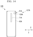
- a ventilator (ventilator) 128A may be provided on the second side plate 63A of the battery module 127A.
- the ventilator 128A may have a functional film which is permeable to gases but not permeable to a liquid.
- the ventilator 128A allows gases inside and outside the second box 51A to flow back and forth and makes a liquid impossible to flow therebetween.
- the storage batteries 52A to 54A fail, there are cases in which gases are released from the storage batteries 52A to 54A. If the electricity storage device 126 is configured as described above, when a pressure of the gases released from the storage batteries 52A to 54A becomes higher than a certain pressure, the gases can be discharged to the outside of the second box 51A through the ventilator 128A. Therefore, an excessive pressure increase in the second box 51A can be inhibited.
- the modified examples of the electricity storage devices 121 and 126 can also be applied to the second embodiment.
- the battery modules 28A to 28C and 98A to 98C may not be attachable to and detachable from the first box 27 but may be fixed to the first box 27.
- the battery modules 28A to 28C and 98A to 98C may not include the packings 55A to 55C.
- the storage batteries 52A to 54A or the like can be efficiently cooled without using a fan.
Landscapes
- Engineering & Computer Science (AREA)
- Chemical & Material Sciences (AREA)
- Chemical Kinetics & Catalysis (AREA)
- Electrochemistry (AREA)
- General Chemical & Material Sciences (AREA)
- Manufacturing & Machinery (AREA)
- Transportation (AREA)
- Mechanical Engineering (AREA)
- Aviation & Aerospace Engineering (AREA)
- Automation & Control Theory (AREA)
- Battery Mounting, Suspending (AREA)
- Secondary Cells (AREA)
Description
- Embodiments described herein relate generally to an electricity storage device and a railroad car.
- Generally, a railroad car receives supply of power from an overhead line or a power generation system mounted on the railroad car. A railroad car includes an electricity storage device as an emergency power supply for securing certain functions for a certain period of time when supply of power is cut off. In recent years, since energy densities of storage batteries have increased, electricity storage devices mounted on a railroad car have been used as an emergency power supply combined with a system for supplying power to a drive system.
- Battery modules are housed in an electricity storage device. A plurality of storage batteries in which electrodes and electrolytic solutions are housed are disposed inside the battery module. Conductors for connecting the storage batteries to each other and a control device of the storage batteries are also housed inside the battery module.
- Storage batteries generate heat. Therefore, cooling of storage batteries with a fan to release heat generated from the storage batteries to the outside of the electricity storage device has been studied.
- Generally, in a cooling system having a fan, a failure detection function for detecting a failure of the fan needs to be provided and the fan needs to be replaced on a regular basis according to the service life. Also, since external air is forcibly taken into the electricity storage device using a fan, a filter for removing dust and foreign matter needs to be provided upstream of the fan. Therefore, the filter needs to be replaced on a regular basis.
-
- [Patent Document 1]
Japanese Unexamined Patent Application, First Publication No. 2010-055973 - [Patent Document 2] European Patent Application
EP 3 196 974 A - A problem to be solved by the present invention is to provide an electricity storage device and a railroad car in which storage batteries can be efficiently cooled without using a fan.
- An electricity storage device according to the embodiment includes a first box, a second box, a storage battery, and a flow path. The second box includes a side plate and is housed in the first box. The storage battery is disposed in the second box while being connected to the side plate. The flow path is configured to include the side plate of the second box inside the first box and outside the second box and vertically penetrates the first box.
-
-
FIG. 1 is a front view showing an electricity storage device of a railroad car of a first embodiment. -
FIG. 2 is a plan view showing the electricity storage device of the railroad car of the first embodiment. -
FIG. 3 is a cross-sectional view taken along section line A1-A1 inFIG. 1 . -
FIG. 4 is a plan view showing the electricity storage device of the first embodiment. -
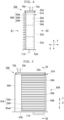
FIG. 5 is a view in a direction of arrow B1 inFIG. 4 . -
FIG. 6 is a view in a direction of arrow B2 inFIG. 4 . -
FIG. 7 is a cross-sectional view taken along section line A2-A2 inFIG. 5 . -
FIG. 8 is a cross-sectional view of an electricity storage device of a railroad car of a second embodiment as seen from above. -
FIG. 9 is a plan view showing an electricity storage device of the second embodiment. -
FIG. 10 is a view in a direction of arrow B4 inFIG. 9 . -
FIG. 11 is a cross-sectional view taken along section line A4-A4 inFIG. 10 . -
FIG. 12 is a side view showing a main part of an electricity storage device of a modified example in the railroad car of the embodiment. -
FIG. 13 is a view in a direction of arrow B6 inFIG. 12 . -
FIG. 14 is a side view showing a main part of an electricity storage device of a modified example in the railroad car of the embodiment. - Hereinafter, an electricity storage device and a railroad car according to an embodiment will be described with reference to the drawings.
- Hereinafter, a first embodiment of an electricity storage device of a railroad car will be described with reference to
FIGS. 1 to 7 . - As shown in
FIGS. 1 to 3 , anelectricity storage device 26 of the present embodiment includes afirst box 27, a plurality (three in the present embodiment) of battery modules 28, aprotection circuit 29, and acontrol circuit 30. Further, the number of battery modules 28 included in theelectricity storage device 26 is not limited, and may be one, two, or four or more. Theelectricity storage device 26 is mounted, for example, under a floor of a car body of the railroad car. - Hereinafter, when the plurality of battery modules 28 are distinguished for indicating them individually, they are referred to as a
battery module 28A, abattery module 28B, and abattery module 28C in order from the front toward the rear of the car body. When referring to thebattery modules - An external form of the
first box 27 is formed in a rectangular parallelepiped box shape. Thefirst box 27 includes a firsttop plate 33, afirst bottom plate 34, andfirst side plates 35 to 38. The firsttop plate 33, thefirst bottom plate 34, and thefirst side plates 35 to 38 are formed of a steel plate or the like. - For example, the first
top plate 33 and thefirst bottom plate 34 are formed in a rectangular shape that is long in a longitudinal direction X (hereinafter, simply referred to as a longitudinal direction X) of the car body in plan view. The firsttop plate 33 and thefirst bottom plate 34 are disposed to face each other in a vertical direction. Thefirst side plates first bottom plate 34. Thefirst side plates first bottom plate 34 in a width direction Y (hereinafter, simply referred to as a width direction Y) of the car body. - Further, the
first side plate 36 side with respect to thefirst side plate 35 is referred to as a right side, and thefirst side plate 35 side with respect to thefirst side plate 36 is referred to as a left side. Thefirst side plate 37 side with respect to thefirst side plate 38 is referred to as the front, and thefirst side plate 38 side with respect to thefirst side plate 37 is referred to as the rear. - As shown in
FIG. 2 , a plurality of first through-holes 33a are formed in the front portion of the firsttop plate 33. The plurality of first through-holes 33a are disposed in a grid pattern. As shown inFIGS. 1 and2 , amounting member 39 for fixing thefirst box 27 to the car body is fixed to each corner of the firsttop plate 33. The mountingmember 39 protrudes upward with respect to the firsttop plate 33 of thefirst box 27. - Although not shown, a plurality of first through-holes are formed in the
first bottom plate 34 at a position facing the plurality of first through-holes 33a of the firsttop plate 33. - As shown in
FIG. 3 , an opening 35a is formed in the front portion of thefirst side plate 35. Afirst partition plate 40 extending to the right side is attached to an edge portion of thefirst side plate 35 behind theopening 35a. Thefirst partition plate 40 extends to an intermediate portion between thefirst side plate 35 and thefirst side plate 36. - Further, as shown in
FIG. 1 , aninspection cover 35b is provided in the rear portion of thefirst side plate 35. Theinspection cover 35b is used for inspection work of theprotection circuit 29 and thecontrol circuit 30. - As shown in
FIG. 3 , a first partition plate (partition plate) 41 extending to the front is attached to a right end portion of thefirst partition plate 40. Thefirst partition plates first box 27. Thefirst partition plate 41 includes a platemain body 42 and a plurality of receiving members 43. - The plate
main body 42 extends to the front from the right end portion of thefirst partition plate 40 until reaching thefirst side plate 37. The platemain body 42 is joined to thefirst side plate 37 by welding or the like. - The
first partition plate 40 and the platemain body 42 extend to the firsttop plate 33 and thefirst bottom plate 34 and are joined to the firsttop plate 33 and thefirst bottom plate 34 by welding or the like. - A plurality (three in the present embodiment) of openings 42aA, 42aB, and 42aC are formed in the plate
main body 42. Each of the openings 42a is formed in a rectangular frame shape when viewed in the width direction Y. The plurality of openings 42aA, 42aB, and 42aC are disposed to be aligned in that order from the front to the rear in the longitudinal direction X with spaces therebetween. - A receiving
member 43A (one of the plurality of receiving members 43) described above is fixed to an edge portion of the opening 42aA in the platemain body 42. The receivingmember 43A is formed in a rectangular frame shape when viewed in the width direction Y. The receivingmember 43A protrudes toward a left side from the platemain body 42 over the entire circumference of the edge portion of the opening 42aA. - Similarly, in the plate
main body 42, the receivingmember 43B is fixed to an edge portion of the opening 42aB, and the receivingmember 43C is fixed to an edge portion of the opening 42aC. - The opening 42aA of the plate
main body 42 and the opening of the receivingmember 43A constitute a first opening 41aA of thefirst partition plate 41. Similarly, the opening 42aB of the platemain body 42 and the opening of the receivingmember 43B constitute a first opening 41aB of thefirst partition plate 41. The opening 42aC of the platemain body 42 and the opening of the receivingmember 43C constitute a first opening 41aC of thefirst partition plate 41. - An
opening 36a is formed in the front portion of thefirst side plate 36. Theopening 36a of thefirst side plate 36 is covered with awork cover 45. Thework cover 45 is detachably attached to thefirst side plate 36 by afastening member 46 such as a bolt or a screw. - The plurality of battery modules 28 include a
battery module 28A, abattery module 28B, and abattery module 28C. - A configuration of the
battery module 28A and configurations of thebattery modules battery module 28A are denoted by adding a capital letter "A" to a numeral, or a numeral and a lowercase letter. The components of thebattery modules battery module 28A are denoted by adding a capital letter "B" or "C" to the same numeral, or the same numeral and lowercase letter as in thebattery module 28A. Therefore, duplicated description will be omitted. - For example, a
second box 51A, to be described below, of thebattery module 28A andsecond boxes battery modules - As shown in
FIGS. 4 to 7 , thebattery module 28A includes thesecond box 51A, a plurality (three in the present embodiment) ofstorage batteries - An external form of the
second box 51A is formed in a rectangular parallelepiped box shape. A right side of thesecond box 51A opens to form a second opening 51aA in thesecond box 51A. Thesecond box 51A is housed in thefirst box 27. - The
second box 51A includes a secondtop plate 59A, asecond bottom plate 60A, andsecond side plates 61A to 63A. - For example, the second
top plate 59A and thesecond bottom plate 60A are formed in a rectangular shape that is long in the width direction Y. The secondtop plate 59A and thesecond bottom plate 60A are disposed to face each other in a vertical direction. - The
second side plates second bottom plate 60A. Thesecond side plate 61A is disposed in the front of thesecond bottom plate 60A, and thesecond side plate 62A is disposed in the rear of thesecond bottom plate 60A. Thesecond side plate 63A is provided to stand upright on a left outer edge portion in the longitudinal direction X of thesecond bottom plate 60A. - As shown in
FIG. 5 , thesecond side plate 61A includes a side platemain body 65A and a base (side plate) 66A. An opening 65aA is formed in an upper portion of the side platemain body 65A. The opening 65aA is formed at a central portion in the width direction Y of the side platemain body 65A. As shown inFIG. 7 , a receiving part 65bA is formed at a right end portion of the side platemain body 65A by the side platemain body 65A forming a step forward. - As shown in
FIG. 5 , thebase 66A is disposed in the front of the opening 65aA of the side platemain body 65A. Thebase 66A and the side platemain body 65A are fixed by a fastening member (not shown). Further, the entiresecond side plate 61A may be configured by the base. - The second
top plate 59A, thesecond bottom plate 60A, thesecond side plates 62 and 63A, and the side platemain body 65A are formed of a steel plate or the like. - As shown in
FIGS. 4 and 5 , a plurality of fin members (protrusions) 68A are provided on thebase 66A. Thebase 66A and the plurality offin members 68A constitute a heat-dissipation fin 69A. - Further, the number of
fin members 68A provided on thebase 66A is not limited and may be one. Thefin members 68A may not be provided on thebase 66A. - The plurality of
fin members 68A are formed in a plate shape such that a thickness direction thereof is the width direction Y and protrude toward the front from thebase 66A. The plurality offin members 68A extend in the vertical direction. The plurality offin members 68A are disposed to be aligned in the width direction Y with spaces therebetween. - For example, the
base 66A and the plurality offin members 68A may be integrally formed by extrusion molding using aluminum or the like. - As shown in
FIG. 7 , a receiving part 62aA is formed at a right end portion of thesecond side plate 62A by thesecond side plate 62A forming a step rearward. On the secondtop plate 59A and thesecond bottom plate 60A, receiving parts (reference numerals omitted) similar to the receiving part 65bA of the side platemain body 65A and the receiving part 62aA of thesecond side plate 62A are formed. - The
second side plate 63A protrudes to the front to a front end portion of the heat-dissipation fin 69A. Thesecond side plate 63A protrudes to the rear with respect to thesecond side plate 62A. - As shown in
FIG. 5 , ahandle 71A extending in the vertical direction is fixed to thesecond side plate 63A. - Types of the
storage batteries 52A to 54A are not particularly limited. For example, thestorage batteries 52A to 54A are lithium ion secondary batteries. As shown inFIG. 7 , thestorage batteries 52A to 54A are disposed to be aligned in that order from the left to the right in the width direction Y with spaces therebetween. Thestorage batteries 52A to 54A are disposed in thesecond box 51A while being connected to thebase 66A. Further, the term "connect" as used in the present specification means not only connecting something in direct contact without other members interposed, but also connecting something in indirect contact with other members interposed. - Further, the number of storage batteries included in the
battery module 28A is not limited, and may be one, two, or four or more. - It is preferable that temperature sensors and voltage sensors be attached to the
storage batteries 52A to 54A. The temperature sensor measures a temperature of an outer surface or the like of thestorage batteries 52A to 54A. The voltage sensor measures a voltage value output from thestorage batteries 52A to 54A. - As shown in
FIG. 6 , thestorage battery 52A and thestorage battery 53A, and thestorage battery 53A and thestorage battery 54A are connected byelectric wires electric wire 75A is connected to thestorage battery 52A. Anelectric wire 76A is connected to thestorage battery 54A. The threestorage batteries 52A to 54A are connected in series by theelectric wires 73A to 76A so that power of thestorage batteries 52A to 54A is taken out to the outside. - As shown in
FIG. 7 , thestorage batteries 52A to 54A are fixed to a rear surface of thebase 66A by a fastening member (not shown) or the like. It is preferable that a compound having high thermal conductivity be disposed between thestorage batteries 52A to 54A and thebase 66A. - As shown in
FIG. 6 , thestorage batteries 52A to 54A are disposed on an upper portion of thebattery module 28A. Theelectric wires 73A to 76A described above are routed around a lower portion of thebattery module 28A. - As shown in
FIGS. 6 and 7 , the packing 55A is formed in a rectangular frame shape when viewed in the width direction Y. Thepacking 55A is formed using hollow rubber or the like. The packing 56A is fixed to the receiving part 65b of the side platemain body 65A, the receiving part 62aA of thesecond side plate 62A, and the receiving parts of the secondtop plate 59A and thesecond bottom plate 60A with the right side thereof exposed. The packing 56A is fixed to an edge portion of the second opening 51aA in thesecond box 51A. - Further, the packing 56A may be fixed to an edge portion of the first opening 41aA in the
first partition plate 41. - As shown in
FIG. 3 , a length in the longitudinal direction X of theentire battery modules 28A to 28C configured as described above and alength 35 in the longitudinal direction X of theopening 35a of the first side plate are equal to each other. Thesecond box 51A of thebattery module 28A is detachably attached to thefirst box 27 through theopening 35a of thefirst side plate 35. When the edge portion of the first opening 41aA of thefirst partition plate 41 comes into contact with thepacking 55A of thebattery module 28A, the edge portion of the first opening 41aA of thefirst partition plate 41 and the edge portion of the second opening 51aA of thesecond box 51A are hermetically connected over the entire circumference of both the edge portions, and thereby thesecond box 51A is attached to thefirst box 27. At this time, the first opening 41aA of thefirst partition plate 41 communicates with the second opening 51aA of thesecond box 51A. - The
second boxes battery modules first box 27 in the same manner. - At this time, a
flow path 79A is configured by the plurality of first through-holes 33a of the firsttop plate 33, the plurality of first through-holes of thefirst bottom plate 34, thefirst side plate 37, and thefirst partition plate 41 of thefirst box 27, and the packing 55A, thesecond side plate 63A, and thebase 66A of the heat-dissipation fin 69A of thebattery module 28A. Theflow path 79A is configured by thefirst box 27 and thebattery module 28A. - The
flow path 79A is formed inside thefirst box 27 and outside thesecond box 51A and penetrates thefirst box 27 in the vertical direction. Thebase 66A of the heat-dissipation fin 69A constitutes a part of theflow path 79A. - The plurality of
fin members 68A of the heat-dissipation fin 69A protrude toward the inside of theflow path 79A from thebase 66A. - A
flow path 79B is configured by the plurality of first through-holes 33a of the firsttop plate 33, the plurality of first through-holes of thefirst bottom plate 34, and thefirst partition plate 41 of thefirst box 27, the packing 55A, thesecond side plate 62A, and thesecond side plate 63A of thebattery module 28A, and apacking 55B, asecond side plate 63B, and a base 66B of a heat-dissipation fin 69B of thebattery module 28B. Theflow path 79B is configured by thefirst box 27 and thebattery modules - In the same manner, a
flow path 79C is configured by thefirst box 27, thebattery module 28B, and thebattery module 28C. - Further, the
second side plate 63A of thebattery module 28A and thefirst box 27 are fixed by afastening member 72A (seeFIG. 1 ). Theflow paths bases dissipation fins - The
electric wire 75A of thebattery module 28A and anelectric wire 76B of thebattery module 28B are connected by anelectric wire 82. Anelectric wire 75B of thebattery module 28B and anelectric wire 76C of thebattery module 28C are connected by anelectric wire 83. Anelectric wire 84 is connected to theelectric wire 76A of thebattery module 28A. Anelectric wire 85 is connected to anelectric wire 75C of thebattery module 28C. Theelectric wires protection circuit 29. - The nine
storage batteries 52A to 54A, 52B to 54B, and 52C to 54C (hereinafter abbreviated asstorage batteries 52A to 54A or the like) in the threebattery modules 28A to 28C are connected in series by theelectric wires 82 to 85, and power of thestorage batteries 52A to 54A or the like is taken out to the outside. - Temperatures detected from the
battery modules 28A to 28C by the temperature sensors and voltages detected therefrom by the voltage sensors are transmitted. The temperatures and voltages are transmitted to thecontrol circuit 30 by theelectric wires battery modules 28A to 28C in series. - Further, the
electric wire 87a connects thebattery module 28A and thebattery module 28B. Theelectric wire 87b connects thebattery module 28B and thebattery module 28C. Theelectric wire 87c connects thebattery module 28C and thecontrol circuit 30. - The
protection circuit 29 includes a contactor or the like. Thecontrol circuit 30 includes a printed circuit board or the like. Theprotection circuit 29 and thecontrol circuit 30 are connected to an upper level controller (not shown). - The
control circuit 30 aggregates temperatures and voltages transmitted from thebattery modules 28A to 28C. Then, for example, when at least one of the transmitted temperatures is higher than a predetermined temperature threshold value, a warning is sent to the upper level controller. - The
protection circuit 29 opens the contactor on the basis of an instruction from the upper controller. - Next, in the
electricity storage device 26 configured as described above, a procedure for attaching thebattery modules 28A to 28C to thefirst box 27 from a state in which thebattery modules 28A to 28C are not attached to thefirst box 27 will be described. - An operator grasps the
handle 71A of thebattery module 28A and inserts thebattery module 28A into thefirst box 27 through theopening 35a of thefirst box 27. The edge portion of the first opening 41aA of thefirst partition plate 41 is brought into contact with thepacking 55A of thebattery module 28A to attach thebattery module 28A to thefirst box 27. Thebattery module 28A is fixed to thefirst box 27 using thefastening member 72A. In the same manner, thebattery modules first box 27. - The
fastening member 46 and thework cover 45 are removed from thefirst box 27. The operator inserts a hand or the like into thefirst box 27 through theopening 36a of thefirst side plate 36. Thebattery modules 28A to 28C, theprotection circuit 29, and thecontrol circuit 30 are connected to each other using theelectric wires 82 to 85 and 87a to 87c. - When the connection is completed, the
opening 36a of thefirst side plate 36 is closed with thefastening member 46 and thework cover 45. - Next, cooling of the
electricity storage device 26 configured as described above will be described. - The
storage batteries 52A to 54A or the like of theelectricity storage device 26 generate heat when supplying power or storing power. - The heat generated by the
storage batteries 52A to 54A is transmitted to the plurality offin members 68A via thebase 66A of the heat-dissipation fin 69A. When the heat is transmitted to the heat-dissipation fin 69A, thestorage batteries 52A to 54A are cooled. - Air near the heat-
dissipation fin 69A in theflow path 79A increases in temperature due to the heat transmitted from thestorage batteries 52A to 54A and is expanded to a lower density. The air with the lowered density moves upward through spaces between thefin members 68A adjacent to each other in the width direction Y. The air that has moved upward flows to the outside of theelectricity storage device 26 through the plurality of first through-holes 33a of thebattery module 28A. - On the other hand, since a pressure in the
flow path 79A decreases, air having a relatively low temperature outside theelectricity storage device 26 is suctioned into theflow path 79A from the plurality of first through-holes of thefirst bottom plate 34. The air may include dust or the like due to an influence of a track below the car body. However, since the edge portion of the first opening 41aA in thefirst partition plate 41 and the edge portion of the second opening 51aA in thesecond box 51A are hermetically connected by the packing 55A, the air flowing in theflow path 79A is inhibited from flowing into a region inside thefirst box 27 in which thestorage batteries 52A to 54A are disposed. - Similarly, the
storage batteries 52B to 54B and 52C to 54C are cooled by the air flowing in theflow paths - As described above, air is suctioned into the
flow paths 79A to 79C by a so-called chimney effect without using a fan. Therefore, theelectricity storage device 26 can efficiently cool thestorage batteries 52A to 54A or the like by a natural cooling method. - As described above, according to the
electricity storage device 26 of the present embodiment, the air flowing through theflow path 79A that is configured to include thebase 66A to which thestorage batteries 52B to 54B are connected flows out to the outside. Then, a pressure in theflow path 79A decreases, and air having a relatively low temperature is suctioned into theflow path 79A from the outside. Accordingly, thestorage batteries 52A to 54A can be efficiently cooled without using a fan. Since no fan is used, maintenance of theelectricity storage device 26 is facilitated. - Since the
electricity storage device 26 includes the plurality offin members 68A, heat transmitted to thebase 66A from thestorage batteries 52A to 54A can be efficiently transmitted to the air in theflow path 79A. - When the
second box 51A of thebattery module 28A is attached to thefirst box 27, the first opening 41aA of thefirst partition plate 41 communicates with the second opening 51aA of thesecond box 51A. Therefore, the air in theflow path 79A flowing into thesecond box 51A can be inhibited. - The packing 55A is fixed to the edge portion of the second opening 51aA in the
second box 51A. Therefore, a hermetic connection between the edge portion of the first opening 41aA in thefirst partition plate 41 and the edge portion of the second opening 51aA in thesecond box 51A can be hermetically connected more reliably. - Also, according to the railroad car of the present embodiment, a railroad car can be configured using the
electricity storage device 26 in which thestorage batteries 52A to 54A can be efficiently cooled without using a fan. - Next, a second embodiment of an electricity storage device of a railroad car will be described with reference to
FIGS. 8 to 11 , but components the same as those in the above-described embodiment will be denoted by the same reference numerals, detailed description thereof will be omitted, and only different points will be described. - As shown in
FIG. 8 , anelectricity storage device 96 of the present embodiment includesconnection circuits battery modules battery modules 28A to 28C of theelectricity storage device 26. - The
connection circuit 97A includes aboard 101A andfirst connectors board 101A is disposed in an opening 42aA of a platemain body 42 in afirst box 27. Theboard 101A is fixed to afirst bottom plate 34 or the like of thefirst box 27 such that a thickness direction thereof is a width direction Y. - The
first connectors 102A to 104A are fixed to a left surface of theboard 101A. Thefirst connector 103A, thefirst connector 102A, and thefirst connector 104A are disposed to be aligned in that order from the front toward the rear. Thefirst connector 102A is connected to an end portion of anelectric wire 82. Thefirst connector 103A is connected to an end portion of anelectric wire 84. Thefirst connector 104A is connected to an end portion of anelectric wire 87a. - In the
connection circuit 97B, afirst connector 102B is connected to an end portion of anelectric wire 83. Afirst connector 103B is connected to an end portion of theelectric wire 82. Afirst connector 104B is connected to end portions of theelectric wire 87a and anelectric wire 87b. - In the
connection circuit 97C, the first connector 102C is connected to an end portion of anelectric wire 85. Afirst connector 103C is connected to end portions of theelectric wires first connector 104C is connected to an end portion of theelectric wire 87c. - Further, in the present embodiment, the
opening 36a is not formed in afirst side plate 36 of thefirst box 27. Theelectricity storage device 96 does not include thework cover 45 and thefastening member 46. - As shown in
FIGS. 9 to 11 , thebattery module 98A includes asecond box 107A and aconnection circuit 108A instead of thesecond box 51A and the heat-dissipation fin 69A of thebattery module 28A. - The
second box 107A includes a second side plate (side plate) 111A instead of thesecond side plate 61A of thesecond box 51A. Thesecond side plate 111A is provided to stand upright on an outer edge portion in the width direction Y of asecond bottom plate 60A. Thesecond side plate 111A is formed of a steel plate or the like. - A plurality (three in the present embodiment) of openings 111aA, 111bA, and 111cA are formed in an upper portion of the
second side plate 111A. The openings 111aA to 111cA are formed in a vertically long rectangular shape when viewed in a longitudinal direction X. The openings 111aA to 111cA are disposed to be aligned in that order from the left to the right in the width direction Y with spaces therebetween. - The
storage battery 52A is fixed to thesecond side plate 111A by a fastening member (not shown) to close the opening 111aA of thesecond side plate 111A. In the same manner,storage batteries - As shown in
FIG. 11 , a second opening 107aA is formed in thesecond box 107A instead of the second opening SlaA of thesecond box 51A. - The
connection circuit 108A includes aboard 114A andsecond connectors - The
board 114A is disposed in the second opening 107aA of thesecond box 107A. Theboard 114A is fixed to thesecond box 107A such that a thickness direction thereof is the width direction Y. - The
second connectors 115A to 117A are provided on thesecond box 107A while being electrically connected to thestorage batteries 52A to 54A. Thesecond connectors 115A to 117A are fixed to a right surface of theboard 114A. Thesecond connector 116A, thesecond connector 115A, and thesecond connector 117A are disposed to be aligned in that order from the front toward the rear. Thesecond connector 115A is connected to an end portion of anelectric wire 75A. Thesecond connector 116A is connected to an end portion of anelectric wire 76A. Thesecond connector 117A is connected to a temperature sensor and a voltage sensor. - As shown in
FIG. 8 , thesecond connector 115A is detachably attached to thefirst connector 102A in the width direction Y. Similarly, thesecond connectors first connectors 100A and 104A in the width direction Y. - When the
second box 107A of thebattery module 98A is attached to thefirst box 27, thesecond connectors 115A to 117A of theconnection circuit 108A are respectively attached to thefirst connectors 102A to 104A of theconnection circuit 97A. On the other hand, when thesecond box 107A of thebattery module 98A is removed from thefirst box 27, thesecond connectors 115A to 117A of theconnection circuit 108A are removed from thefirst connectors 102A to 104A of theconnection circuit 97A. - A
flow path 119A is configured by a plurality of first through-holes 33a of a firsttop plate 33, a plurality of first through-holes of thefirst bottom plate 34, afirst side plate 37, and afirst partition plate 41 of thefirst box 27, and apacking 55A, asecond side plate 63A, thesecond side plate 111A, and thestorage batteries 52A to 54A of thebattery module 98A. Thestorage batteries 52A to 54A are exposed in theflow path 119A through the openings 111aA to 111cA. - A
flow path 119B is configured by the plurality of first through-holes 33a of the firsttop plate 33, the plurality of first through-holes of thefirst bottom plate 34, and thefirst partition plate 41 of thefirst box 27, the packing 55A, asecond side plate 62A, and thesecond side plate 63A of thebattery module 98A, and apacking 55B, asecond side plate 63B, asecond side plate 111B, andstorage batteries 52B to 54B of thebattery module 98B. - In the same manner, a
flow path 119C is configured by thefirst box 27, thebattery module 98B, and thebattery module 98C. - Next, in the
electricity storage device 96 configured as described above, a procedure for attaching thebattery modules 98A to 98C to thefirst box 27 from a state in which thebattery modules 98A to 98C are not attached to thefirst box 27 will be described. - An operator grasps a
handle 71A of thebattery module 98A and inserts thebattery module 98A into thefirst box 27 through anopening 35a of thefirst box 27. An edge portion of the first opening 41aA of thefirst partition plate 41 is brought into contact with thepacking 55A of thebattery module 98A to attach thebattery module 98A to thefirst box 27. At this time, thesecond connectors 115A to 117A of theconnection circuit 108A are attached to thefirst connectors 102A to 104A of theconnection circuit 97A, respectively. - In the same manner, the
battery modules first box 27. - In the present embodiment, there is no need to remove the
work cover 45 to perform connection work of theelectric wires 82 to 85 and 87a to 87c after thebattery modules 98A to 98C are attached to thefirst box 27. - Next, cooling of the
electricity storage device 96 configured as described above will be described. - Heat generated by the
storage batteries 52A to 54A is transmitted to air near the openings 111aA to 11 1cA in theflow path 119A. At this time, since thestorage batteries 52A to 54A are in direct contact with the air in theflow path 119A, heat is efficiently transmitted. - Since heat is transmitted to the air, the
storage batteries 52A to 54A are cooled. The air to which heat has been transmitted increases in temperature and is expanded to a lower density. The air with the lowered density moves upward. The air that has moved upward flows to the outside of theelectricity storage device 96 through the plurality of first through-holes 33a or the like of thebattery module 98A. - As described above, according to the
electricity storage device 96 of the present embodiment, thestorage batteries 52A to 54A are in direct contact with the air in theflow path 119A through the openings 111aA to 111 cA. Therefore, heat exchange between thestorage batteries 52A to 54A and the air in theflow path 119A is efficiently performed, and thestorage batteries 52A to 54A can be efficiently cooled without using a fan. - The
electricity storage device 96 includes thefirst connectors 102A to 104A andsecond connectors 115A to 117A. Thesecond connectors 115A to 117A can be attached to thefirst connectors 102A to 104A by simply attaching thesecond box 107A of thebattery module 98A to thefirst box 27. Thesecond connectors 115A to 117A can be removed from thefirst connectors 102A to 104A by simply removing thesecond box 107A of thebattery module 98A from thefirst box 27. - Further, the
electricity storage device 96 may not include theconnection circuits 97A to 97C and 108A to 108C. - In the first embodiment, a through-hole 63aA may be formed in the
second side plate 63A in thesecond box 51A of abattery module 122A as in anelectricity storage device 121 shown inFIGS. 12 and 13 . Then, theelectricity storage device 121 may include acover 123A which removably covers the through-hole 63aA with respect to thesecond side plate 63A. Thecover 123A is detachably attached to thesecond side plate 63A using afastening member 124A such as a bolt or a screw. - There are cases in which the operator needs to visually inspect the
storage batteries 52A to 54A in thesecond box 51A on a regular basis. When it is configured like theelectricity storage device 121 of the modified example described above, thefastening member 124A and thecover 123A can be removed from thesecond side plate 63A of thesecond box 51A, and a state of thestorage batteries 52A to 54A can be visually inspected through the through-hole 63aA. - When the inspection is completed, the
fastening member 124A and thecover 123A are attached to thesecond side plate 63A. - As in an
electricity storage device 126 shown inFIG. 14 , a ventilator (ventilator) 128A may be provided on thesecond side plate 63A of thebattery module 127A. For example, theventilator 128A may have a functional film which is permeable to gases but not permeable to a liquid. Theventilator 128A allows gases inside and outside thesecond box 51A to flow back and forth and makes a liquid impossible to flow therebetween. - For example, when the
storage batteries 52A to 54A fail, there are cases in which gases are released from thestorage batteries 52A to 54A. If theelectricity storage device 126 is configured as described above, when a pressure of the gases released from thestorage batteries 52A to 54A becomes higher than a certain pressure, the gases can be discharged to the outside of thesecond box 51A through theventilator 128A. Therefore, an excessive pressure increase in thesecond box 51A can be inhibited. - The modified examples of the
electricity storage devices - The
battery modules 28A to 28C and 98A to 98C may not be attachable to and detachable from thefirst box 27 but may be fixed to thefirst box 27. - The
battery modules 28A to 28C and 98A to 98C may not include thepackings 55A to 55C. - According to at least one embodiment described above, when the
flow paths 79A to 79C are provided, thestorage batteries 52A to 54A or the like can be efficiently cooled without using a fan. - While certain embodiments have been described, these embodiments have been presented by way of example only, and are not intended to limit the scope of the inventions. The invention is defined by the appended claims.
-
- 26, 96, 121, 126 Electricity storage device
- 27 First box
- 41 First partition plate (partition plate)
- 41aA, 41aB, 41aC First opening
- 51aA, 51aB, 51aC, 107aA Second opening
- 51A, 51B, 51C, 107A, 107B, 107C Second box
- 52A, 52B, 52C, 53A, 53B, 53C, 54A, 54B, 54C Storage battery
- 55A, 55B, 55C Packing (sealing member)
- 63aA Through-hole
- 66A, 66B, 66C Base (side plate)
- 68A Fin member (protrusion)
- 79A, 79B, 79C, 119A, 119B, 119C Flow path
- 102A, 102B, 102C, 103A, 103B, 103C, 104A, 104B, 104C First connector
- 111aA, 111bA, 111cA, 111aB, 111bB, 111cB, 111aC, 111bC, 111cC Opening
- 111A, 111B, 111C Second side plate (side plate)
- 115A, 115B, 115C, 116A, 116, 116C, 117A, 117B, 117C Second connector
- 123A Cover
- 128A Ventilator (ventilator)
Claims (9)
- An electricity storage device (26, 96, 121, 126), comprising:a first box (27);a second box (51A, 51B, 51C, 107A, 107B, 107C) comprising a side plate (61A, 62A, 63A, 111A, 111B, 111C) and housed in the first box (27);a storage battery (52A, 52B, 52C, 53A, 53B, 53C, 54A, 54B, 54C) disposed in the second box (51A, 51B, 51C, 107A, 107B, 107C) while being connected to the side plate (61A, 62A, 63A, 111A, 111B, 111C); anda flow path (79A, 79B, 79C, 119A, 119B, 119C) configured to comprise the side plate (61A, 62A, 63A, 111A, 111B, 111C) of the second box (51A, 51B, 51C, 107A, 107B, 107C) inside the first box (27) and outside the second box (51A, 51B, 51C, 107A, 107B, 107C) and vertically penetrating the first box (27).
- The electricity storage device (26, 96, 121, 126) according to Claim 1, further comprising a protrusion (68A) protruding from the side plate (66A) toward an inside of the flow path (79A, 79B, 79C, 119A, 119B, 119C).
- The electricity storage device (26, 96, 121, 126) according to Claim 1 or 2, whereinan opening (111aA, 111bA, 111cA) is formed in the side plate (111A); andthe storage battery (52A, 52B, 52C, 53A, 53B, 53C, 54A, 54B, 54C) is exposed in the flow path (79A, 79B, 79C, 119A, 119B, 119C) through the opening.
- The electricity storage device (26, 96, 121, 126) according to any one of Claims 1 to 3, further comprising a partition plate (40, 41) provided in the first box (27) to constitute a part of the flow path (79A, 79B, 79C, 119A, 119B, 119C) and having a first opening (41aA, 41aB, 41aC) formed therein, whereinthe second box (51A, 51B, 51C, 107A, 107B, 107C) has a second opening (51aA, 107aA) formed therein,the second box (51A, 51B, 51C, 107A, 107B, 107C) is detachably attached to the first box (27), andthe first opening (41aA, 41aB, 41aC) of the partition plate (40, 41) communicates with the second opening (51aA, 107aA) of the second box (51A, 51B, 51C, 107A, 107B, 107C).
- The electricity storage device (26, 96, 121, 126) according to Claim 4, further comprising a sealing member (55A, 55B, 55C) fixed to one of an edge portion of the first opening (41aA, 41aB, 41aC) in the partition plate (40, 41) and an edge portion of the second opening (51aA, 107aA) in the second box (51A, 51B, 51C, 107A, 107B, 107C), wherein
the other of the edge portion of the first opening (41aA, 41aB, 41aC) in the partition plate (40, 41) and the edge portion of the second opening (51aA, 107aA) in the second box (51A, 51B, 51C, 107A, 107B, 107C) and the sealing member (55A, 55B, 55C) are hermetically connected. - The electricity storage device (26, 96, 121, 126) according to any one of Claims 1 to 5, further comprising:a first connector (102A, 102B, 102C, 103A, 103B, 103C, 104A, 104B, 104C) provided in the first box (27); anda second connector (115A, 115B, 115C, 116A, 116, 116C, 117A, 117B, 117C) provided in the second box (51A, 51B, 51C, 107A, 107B, 107C) to be electrically connected to the storage battery (52A, 52B, 52C, 53A, 53B, 53C, 54A, 54B, 54C) and detachably attached to the first connector (102A, 102B, 102C, 103A, 103B, 103C, 104A, 104B, 104C), whereinthe second connector (115A, 115B, 115C, 116A, 116, 116C, 117A, 117B, 117C) is attached to and detached from the first connector (102A, 102B, 102C, 103A, 103B, 103C, 104A, 104B, 104C) in accordance with attachment and detachment of the second box (51A, 51B, 51C, 107A, 107B, 107C) with respect to the first box (27).
- The electricity storage device (26, 96, 121, 126) according to any one of Claims 1 to 6, whereinthe second box (51A, 51B, 51C, 107A, 107B, 107C) has a through-hole (63aA) formed therein,the electricity storage device (26, 96, 121, 126) further comprising a cover (123A) which removably covers the through-hole (63aA) with respect to the second box (51A, 51B, 51C, 107A, 107B, 107C).
- The electricity storage device (26, 96, 121, 126) according to any one of Claims 1 to 7, further comprising a ventilator (128A) which allows gases inside and outside the second box (51A, 51B, 51C, 107A, 107B, 107C) to flow back and forth.
- A railroad car comprising the electricity storage device (26, 96, 121, 126) according to any one of Claims 1 to 8.
Applications Claiming Priority (2)
| Application Number | Priority Date | Filing Date | Title |
|---|---|---|---|
| JP2017226158A JP6976148B2 (en) | 2017-11-24 | 2017-11-24 | Power storage device and railroad vehicle |
| PCT/JP2018/041472 WO2019102858A1 (en) | 2017-11-24 | 2018-11-08 | Electricity storage device and railroad car |
Publications (3)
| Publication Number | Publication Date |
|---|---|
| EP3716394A1 EP3716394A1 (en) | 2020-09-30 |
| EP3716394A4 EP3716394A4 (en) | 2021-08-18 |
| EP3716394B1 true EP3716394B1 (en) | 2023-09-13 |
Family
ID=66631847
Family Applications (1)
| Application Number | Title | Priority Date | Filing Date |
|---|---|---|---|
| EP18880785.3A Active EP3716394B1 (en) | 2017-11-24 | 2018-11-08 | Electricity storage device and railroad car |
Country Status (6)
| Country | Link |
|---|---|
| US (1) | US11374280B2 (en) |
| EP (1) | EP3716394B1 (en) |
| JP (1) | JP6976148B2 (en) |
| CN (1) | CN111279545B (en) |
| TW (1) | TWI716740B (en) |
| WO (1) | WO2019102858A1 (en) |
Families Citing this family (1)
| Publication number | Priority date | Publication date | Assignee | Title |
|---|---|---|---|---|
| JP2026012952A (en) * | 2022-12-01 | 2026-01-28 | ヤマハ発動機株式会社 | Battery packs and electric vehicles |
Family Cites Families (13)
| Publication number | Priority date | Publication date | Assignee | Title |
|---|---|---|---|---|
| JP3881317B2 (en) * | 2003-01-30 | 2007-02-14 | 川崎重工業株式会社 | Battery box for railway vehicles |
| JP5082185B2 (en) * | 2004-08-23 | 2012-11-28 | パナソニック株式会社 | Lead acid battery |
| JP4940203B2 (en) * | 2008-08-29 | 2012-05-30 | 株式会社日立製作所 | Railway vehicle battery box and railway vehicle |
| JP5330810B2 (en) * | 2008-11-18 | 2013-10-30 | 株式会社日立製作所 | Battery box for storing battery module and railcar equipped with the same |
| KR101218751B1 (en) | 2010-01-06 | 2013-01-07 | 주식회사 엘지화학 | Middle or Large-sized Battery Pack of Improved Cooling Efficiency |
| JP5485128B2 (en) * | 2010-12-17 | 2014-05-07 | 株式会社日立製作所 | Battery unit for railway vehicles |
| JP2014089839A (en) * | 2012-10-29 | 2014-05-15 | Sanyo Electric Co Ltd | Power supply device and vehicle having the same |
| JPWO2014068947A1 (en) | 2012-10-31 | 2016-09-08 | 三洋電機株式会社 | Battery module |
| JP5992311B2 (en) * | 2012-12-06 | 2016-09-14 | 株式会社東芝 | Storage battery device for railway vehicles |
| JP2014135173A (en) * | 2013-01-09 | 2014-07-24 | Toyota Industries Corp | Battery pack |
| US9912019B2 (en) * | 2013-05-20 | 2018-03-06 | Hamilton Sundstrand Corporation | Thermal management of electrical storage devices by coolant pool |
| JP6385766B2 (en) * | 2014-09-17 | 2018-09-05 | 株式会社東芝 | Vehicle storage battery device |
| JP2017097986A (en) * | 2015-11-19 | 2017-06-01 | トヨタ自動車株式会社 | Battery cooling structure |
-
2017
- 2017-11-24 JP JP2017226158A patent/JP6976148B2/en active Active
-
2018
- 2018-09-28 TW TW107134234A patent/TWI716740B/en active
- 2018-11-08 CN CN201880069146.8A patent/CN111279545B/en active Active
- 2018-11-08 WO PCT/JP2018/041472 patent/WO2019102858A1/en not_active Ceased
- 2018-11-08 EP EP18880785.3A patent/EP3716394B1/en active Active
-
2020
- 2020-05-21 US US16/880,263 patent/US11374280B2/en active Active
Also Published As
| Publication number | Publication date |
|---|---|
| JP2019096523A (en) | 2019-06-20 |
| TWI716740B (en) | 2021-01-21 |
| TW201926785A (en) | 2019-07-01 |
| US11374280B2 (en) | 2022-06-28 |
| CN111279545A (en) | 2020-06-12 |
| EP3716394A4 (en) | 2021-08-18 |
| WO2019102858A1 (en) | 2019-05-31 |
| JP6976148B2 (en) | 2021-12-08 |
| US20200280034A1 (en) | 2020-09-03 |
| CN111279545B (en) | 2023-12-01 |
| EP3716394A1 (en) | 2020-09-30 |
Similar Documents
| Publication | Publication Date | Title |
|---|---|---|
| CN103311477B (en) | Battery equipment of railway vehicle and railway vehicle | |
| EP3526068B1 (en) | Battery junction box housing configured to direct crash forces in an electric vehicle | |
| JP5039219B2 (en) | Battery module, battery box, and railcar equipped with the same | |
| CN102405540B (en) | Electric energy storage unit for motor vehicles | |
| US10062977B2 (en) | Module-to-module power connector between battery modules of an energy storage system and arrangement thereof | |
| KR101826090B1 (en) | Battery pack and electrically powered vehicle provided with the same | |
| CN106688137B (en) | Vehicle battery device | |
| JP4465667B2 (en) | Hybrid electric vehicle battery box structure | |
| US10703187B2 (en) | Apparatus for storing electric energy for a motor vehicle | |
| WO2012140791A1 (en) | Secondary battery module | |
| WO2019143029A1 (en) | Battery module housing having easily reusable, recyclable, and reworkable adhesion structure and battery module comprising same | |
| JPWO2012140728A1 (en) | Cell block | |
| EP3716394B1 (en) | Electricity storage device and railroad car | |
| JP7020370B2 (en) | Battery pack | |
| CN117936941A (en) | Battery pack and vehicle | |
| TWI720450B (en) | Battery storage box | |
| JP3861358B2 (en) | Battery holding device | |
| JP7234276B2 (en) | fuel cell system | |
| CN221928384U (en) | Battery pack and vehicle with same | |
| JPWO2012140791A1 (en) | Secondary battery module | |
| JP3849184B2 (en) | Battery module and battery pack | |
| US11688876B2 (en) | Fuel cell system | |
| JP2023101297A (en) | vehicle | |
| KR20250170514A (en) | Power storage device | |
| JP2002364963A (en) | Cooling fan device |
Legal Events
| Date | Code | Title | Description |
|---|---|---|---|
| STAA | Information on the status of an ep patent application or granted ep patent |
Free format text: STATUS: THE INTERNATIONAL PUBLICATION HAS BEEN MADE |
|
| PUAI | Public reference made under article 153(3) epc to a published international application that has entered the european phase |
Free format text: ORIGINAL CODE: 0009012 |
|
| STAA | Information on the status of an ep patent application or granted ep patent |
Free format text: STATUS: REQUEST FOR EXAMINATION WAS MADE |
|
| 17P | Request for examination filed |
Effective date: 20200526 |
|
| AK | Designated contracting states |
Kind code of ref document: A1 Designated state(s): AL AT BE BG CH CY CZ DE DK EE ES FI FR GB GR HR HU IE IS IT LI LT LU LV MC MK MT NL NO PL PT RO RS SE SI SK SM TR |
|
| AX | Request for extension of the european patent |
Extension state: BA ME |
|
| DAV | Request for validation of the european patent (deleted) | ||
| DAX | Request for extension of the european patent (deleted) | ||
| REG | Reference to a national code |
Ref country code: DE Ref legal event code: R079 Free format text: PREVIOUS MAIN CLASS: H01M0010655600 Ipc: H01M0010613000 Ref document number: 602018057700 Country of ref document: DE |
|
| A4 | Supplementary search report drawn up and despatched |
Effective date: 20210716 |
|
| RIC1 | Information provided on ipc code assigned before grant |
Ipc: H01M 10/613 20140101AFI20210712BHEP Ipc: H01M 10/6556 20140101ALI20210712BHEP Ipc: H01M 10/625 20140101ALI20210712BHEP Ipc: H01M 10/6551 20140101ALI20210712BHEP Ipc: H01M 10/6562 20140101ALI20210712BHEP Ipc: H01M 50/20 20210101ALI20210712BHEP Ipc: B61C 3/02 20060101ALI20210712BHEP |
|
| GRAP | Despatch of communication of intention to grant a patent |
Free format text: ORIGINAL CODE: EPIDOSNIGR1 |
|
| STAA | Information on the status of an ep patent application or granted ep patent |
Free format text: STATUS: GRANT OF PATENT IS INTENDED |
|
| INTG | Intention to grant announced |
Effective date: 20230412 |
|
| GRAS | Grant fee paid |
Free format text: ORIGINAL CODE: EPIDOSNIGR3 |
|
| GRAA | (expected) grant |
Free format text: ORIGINAL CODE: 0009210 |
|
| STAA | Information on the status of an ep patent application or granted ep patent |
Free format text: STATUS: THE PATENT HAS BEEN GRANTED |
|
| AK | Designated contracting states |
Kind code of ref document: B1 Designated state(s): AL AT BE BG CH CY CZ DE DK EE ES FI FR GB GR HR HU IE IS IT LI LT LU LV MC MK MT NL NO PL PT RO RS SE SI SK SM TR |
|
| REG | Reference to a national code |
Ref country code: CH Ref legal event code: EP |
|
| REG | Reference to a national code |
Ref country code: DE Ref legal event code: R096 Ref document number: 602018057700 Country of ref document: DE |
|
| REG | Reference to a national code |
Ref country code: IE Ref legal event code: FG4D |
|
| REG | Reference to a national code |
Ref country code: LT Ref legal event code: MG9D |
|
| REG | Reference to a national code |
Ref country code: NL Ref legal event code: MP Effective date: 20230913 |
|
| PG25 | Lapsed in a contracting state [announced via postgrant information from national office to epo] |
Ref country code: GR Free format text: LAPSE BECAUSE OF FAILURE TO SUBMIT A TRANSLATION OF THE DESCRIPTION OR TO PAY THE FEE WITHIN THE PRESCRIBED TIME-LIMIT Effective date: 20231214 |
|
| PG25 | Lapsed in a contracting state [announced via postgrant information from national office to epo] |
Ref country code: SE Free format text: LAPSE BECAUSE OF FAILURE TO SUBMIT A TRANSLATION OF THE DESCRIPTION OR TO PAY THE FEE WITHIN THE PRESCRIBED TIME-LIMIT Effective date: 20230913 Ref country code: RS Free format text: LAPSE BECAUSE OF FAILURE TO SUBMIT A TRANSLATION OF THE DESCRIPTION OR TO PAY THE FEE WITHIN THE PRESCRIBED TIME-LIMIT Effective date: 20230913 Ref country code: NO Free format text: LAPSE BECAUSE OF FAILURE TO SUBMIT A TRANSLATION OF THE DESCRIPTION OR TO PAY THE FEE WITHIN THE PRESCRIBED TIME-LIMIT Effective date: 20231213 Ref country code: LV Free format text: LAPSE BECAUSE OF FAILURE TO SUBMIT A TRANSLATION OF THE DESCRIPTION OR TO PAY THE FEE WITHIN THE PRESCRIBED TIME-LIMIT Effective date: 20230913 Ref country code: LT Free format text: LAPSE BECAUSE OF FAILURE TO SUBMIT A TRANSLATION OF THE DESCRIPTION OR TO PAY THE FEE WITHIN THE PRESCRIBED TIME-LIMIT Effective date: 20230913 Ref country code: HR Free format text: LAPSE BECAUSE OF FAILURE TO SUBMIT A TRANSLATION OF THE DESCRIPTION OR TO PAY THE FEE WITHIN THE PRESCRIBED TIME-LIMIT Effective date: 20230913 Ref country code: GR Free format text: LAPSE BECAUSE OF FAILURE TO SUBMIT A TRANSLATION OF THE DESCRIPTION OR TO PAY THE FEE WITHIN THE PRESCRIBED TIME-LIMIT Effective date: 20231214 Ref country code: FI Free format text: LAPSE BECAUSE OF FAILURE TO SUBMIT A TRANSLATION OF THE DESCRIPTION OR TO PAY THE FEE WITHIN THE PRESCRIBED TIME-LIMIT Effective date: 20230913 |
|
| REG | Reference to a national code |
Ref country code: AT Ref legal event code: MK05 Ref document number: 1612224 Country of ref document: AT Kind code of ref document: T Effective date: 20230913 |
|
| PG25 | Lapsed in a contracting state [announced via postgrant information from national office to epo] |
Ref country code: NL Free format text: LAPSE BECAUSE OF FAILURE TO SUBMIT A TRANSLATION OF THE DESCRIPTION OR TO PAY THE FEE WITHIN THE PRESCRIBED TIME-LIMIT Effective date: 20230913 |
|
| PG25 | Lapsed in a contracting state [announced via postgrant information from national office to epo] |
Ref country code: IS Free format text: LAPSE BECAUSE OF FAILURE TO SUBMIT A TRANSLATION OF THE DESCRIPTION OR TO PAY THE FEE WITHIN THE PRESCRIBED TIME-LIMIT Effective date: 20240113 |
|
| PG25 | Lapsed in a contracting state [announced via postgrant information from national office to epo] |
Ref country code: AT Free format text: LAPSE BECAUSE OF FAILURE TO SUBMIT A TRANSLATION OF THE DESCRIPTION OR TO PAY THE FEE WITHIN THE PRESCRIBED TIME-LIMIT Effective date: 20230913 |
|
| PG25 | Lapsed in a contracting state [announced via postgrant information from national office to epo] |
Ref country code: ES Free format text: LAPSE BECAUSE OF FAILURE TO SUBMIT A TRANSLATION OF THE DESCRIPTION OR TO PAY THE FEE WITHIN THE PRESCRIBED TIME-LIMIT Effective date: 20230913 |
|
| PG25 | Lapsed in a contracting state [announced via postgrant information from national office to epo] |
Ref country code: SM Free format text: LAPSE BECAUSE OF FAILURE TO SUBMIT A TRANSLATION OF THE DESCRIPTION OR TO PAY THE FEE WITHIN THE PRESCRIBED TIME-LIMIT Effective date: 20230913 Ref country code: RO Free format text: LAPSE BECAUSE OF FAILURE TO SUBMIT A TRANSLATION OF THE DESCRIPTION OR TO PAY THE FEE WITHIN THE PRESCRIBED TIME-LIMIT Effective date: 20230913 Ref country code: IS Free format text: LAPSE BECAUSE OF FAILURE TO SUBMIT A TRANSLATION OF THE DESCRIPTION OR TO PAY THE FEE WITHIN THE PRESCRIBED TIME-LIMIT Effective date: 20240113 Ref country code: ES Free format text: LAPSE BECAUSE OF FAILURE TO SUBMIT A TRANSLATION OF THE DESCRIPTION OR TO PAY THE FEE WITHIN THE PRESCRIBED TIME-LIMIT Effective date: 20230913 Ref country code: EE Free format text: LAPSE BECAUSE OF FAILURE TO SUBMIT A TRANSLATION OF THE DESCRIPTION OR TO PAY THE FEE WITHIN THE PRESCRIBED TIME-LIMIT Effective date: 20230913 Ref country code: CZ Free format text: LAPSE BECAUSE OF FAILURE TO SUBMIT A TRANSLATION OF THE DESCRIPTION OR TO PAY THE FEE WITHIN THE PRESCRIBED TIME-LIMIT Effective date: 20230913 Ref country code: AT Free format text: LAPSE BECAUSE OF FAILURE TO SUBMIT A TRANSLATION OF THE DESCRIPTION OR TO PAY THE FEE WITHIN THE PRESCRIBED TIME-LIMIT Effective date: 20230913 Ref country code: SK Free format text: LAPSE BECAUSE OF FAILURE TO SUBMIT A TRANSLATION OF THE DESCRIPTION OR TO PAY THE FEE WITHIN THE PRESCRIBED TIME-LIMIT Effective date: 20230913 Ref country code: PT Free format text: LAPSE BECAUSE OF FAILURE TO SUBMIT A TRANSLATION OF THE DESCRIPTION OR TO PAY THE FEE WITHIN THE PRESCRIBED TIME-LIMIT Effective date: 20240115 |
|
| PG25 | Lapsed in a contracting state [announced via postgrant information from national office to epo] |
Ref country code: PL Free format text: LAPSE BECAUSE OF FAILURE TO SUBMIT A TRANSLATION OF THE DESCRIPTION OR TO PAY THE FEE WITHIN THE PRESCRIBED TIME-LIMIT Effective date: 20230913 Ref country code: IT Free format text: LAPSE BECAUSE OF FAILURE TO SUBMIT A TRANSLATION OF THE DESCRIPTION OR TO PAY THE FEE WITHIN THE PRESCRIBED TIME-LIMIT Effective date: 20230913 |
|
| REG | Reference to a national code |
Ref country code: DE Ref legal event code: R097 Ref document number: 602018057700 Country of ref document: DE |
|
| REG | Reference to a national code |
Ref country code: CH Ref legal event code: PL |
|
| PG25 | Lapsed in a contracting state [announced via postgrant information from national office to epo] |
Ref country code: MC Free format text: LAPSE BECAUSE OF FAILURE TO SUBMIT A TRANSLATION OF THE DESCRIPTION OR TO PAY THE FEE WITHIN THE PRESCRIBED TIME-LIMIT Effective date: 20230913 |
|
| PG25 | Lapsed in a contracting state [announced via postgrant information from national office to epo] |
Ref country code: DK Free format text: LAPSE BECAUSE OF FAILURE TO SUBMIT A TRANSLATION OF THE DESCRIPTION OR TO PAY THE FEE WITHIN THE PRESCRIBED TIME-LIMIT Effective date: 20230913 |
|
| PG25 | Lapsed in a contracting state [announced via postgrant information from national office to epo] |
Ref country code: LU Free format text: LAPSE BECAUSE OF NON-PAYMENT OF DUE FEES Effective date: 20231108 |
|
| PG25 | Lapsed in a contracting state [announced via postgrant information from national office to epo] |
Ref country code: CH Free format text: LAPSE BECAUSE OF NON-PAYMENT OF DUE FEES Effective date: 20231130 |
|
| PLBE | No opposition filed within time limit |
Free format text: ORIGINAL CODE: 0009261 |
|
| STAA | Information on the status of an ep patent application or granted ep patent |
Free format text: STATUS: NO OPPOSITION FILED WITHIN TIME LIMIT |
|
| PG25 | Lapsed in a contracting state [announced via postgrant information from national office to epo] |
Ref country code: MC Free format text: LAPSE BECAUSE OF FAILURE TO SUBMIT A TRANSLATION OF THE DESCRIPTION OR TO PAY THE FEE WITHIN THE PRESCRIBED TIME-LIMIT Effective date: 20230913 Ref country code: LU Free format text: LAPSE BECAUSE OF NON-PAYMENT OF DUE FEES Effective date: 20231108 Ref country code: DK Free format text: LAPSE BECAUSE OF FAILURE TO SUBMIT A TRANSLATION OF THE DESCRIPTION OR TO PAY THE FEE WITHIN THE PRESCRIBED TIME-LIMIT Effective date: 20230913 Ref country code: CH Free format text: LAPSE BECAUSE OF NON-PAYMENT OF DUE FEES Effective date: 20231130 |
|
| REG | Reference to a national code |
Ref country code: BE Ref legal event code: MM Effective date: 20231130 |
|
| 26N | No opposition filed |
Effective date: 20240614 |
|
| GBPC | Gb: european patent ceased through non-payment of renewal fee |
Effective date: 20231213 |
|
| REG | Reference to a national code |
Ref country code: IE Ref legal event code: MM4A |
|
| PG25 | Lapsed in a contracting state [announced via postgrant information from national office to epo] |
Ref country code: IE Free format text: LAPSE BECAUSE OF NON-PAYMENT OF DUE FEES Effective date: 20231108 |
|
| PG25 | Lapsed in a contracting state [announced via postgrant information from national office to epo] |
Ref country code: GB Free format text: LAPSE BECAUSE OF NON-PAYMENT OF DUE FEES Effective date: 20231213 |
|
| PG25 | Lapsed in a contracting state [announced via postgrant information from national office to epo] |
Ref country code: BE Free format text: LAPSE BECAUSE OF NON-PAYMENT OF DUE FEES Effective date: 20231130 |
|
| PGFP | Annual fee paid to national office [announced via postgrant information from national office to epo] |
Ref country code: FR Payment date: 20240909 Year of fee payment: 7 |
|
| PG25 | Lapsed in a contracting state [announced via postgrant information from national office to epo] |
Ref country code: SI Free format text: LAPSE BECAUSE OF FAILURE TO SUBMIT A TRANSLATION OF THE DESCRIPTION OR TO PAY THE FEE WITHIN THE PRESCRIBED TIME-LIMIT Effective date: 20230913 |
|
| PG25 | Lapsed in a contracting state [announced via postgrant information from national office to epo] |
Ref country code: SI Free format text: LAPSE BECAUSE OF FAILURE TO SUBMIT A TRANSLATION OF THE DESCRIPTION OR TO PAY THE FEE WITHIN THE PRESCRIBED TIME-LIMIT Effective date: 20230913 Ref country code: IE Free format text: LAPSE BECAUSE OF NON-PAYMENT OF DUE FEES Effective date: 20231108 Ref country code: GB Free format text: LAPSE BECAUSE OF NON-PAYMENT OF DUE FEES Effective date: 20231213 Ref country code: BE Free format text: LAPSE BECAUSE OF NON-PAYMENT OF DUE FEES Effective date: 20231130 |
|
| PG25 | Lapsed in a contracting state [announced via postgrant information from national office to epo] |
Ref country code: BG Free format text: LAPSE BECAUSE OF FAILURE TO SUBMIT A TRANSLATION OF THE DESCRIPTION OR TO PAY THE FEE WITHIN THE PRESCRIBED TIME-LIMIT Effective date: 20230913 |
|
| PG25 | Lapsed in a contracting state [announced via postgrant information from national office to epo] |
Ref country code: BG Free format text: LAPSE BECAUSE OF FAILURE TO SUBMIT A TRANSLATION OF THE DESCRIPTION OR TO PAY THE FEE WITHIN THE PRESCRIBED TIME-LIMIT Effective date: 20230913 |
|
| PG25 | Lapsed in a contracting state [announced via postgrant information from national office to epo] |
Ref country code: CY Free format text: LAPSE BECAUSE OF FAILURE TO SUBMIT A TRANSLATION OF THE DESCRIPTION OR TO PAY THE FEE WITHIN THE PRESCRIBED TIME-LIMIT; INVALID AB INITIO Effective date: 20181108 |
|
| PG25 | Lapsed in a contracting state [announced via postgrant information from national office to epo] |
Ref country code: HU Free format text: LAPSE BECAUSE OF FAILURE TO SUBMIT A TRANSLATION OF THE DESCRIPTION OR TO PAY THE FEE WITHIN THE PRESCRIBED TIME-LIMIT; INVALID AB INITIO Effective date: 20181108 |
|
| REG | Reference to a national code |
Ref country code: DE Ref legal event code: R081 Ref document number: 602018057700 Country of ref document: DE Owner name: KABUSHIKI KAISHA TOSHIBA, JP Free format text: FORMER OWNERS: KABUSHIKI KAISHA TOSHIBA, TOKYO, JP; TOSHIBA INFRASTRUCTURE SYSTEMS & SOLUTIONS CORPORATION, KAWASAKI-SHI, KANAGAWA, JP |
|
| PG25 | Lapsed in a contracting state [announced via postgrant information from national office to epo] |
Ref country code: TR Free format text: LAPSE BECAUSE OF FAILURE TO SUBMIT A TRANSLATION OF THE DESCRIPTION OR TO PAY THE FEE WITHIN THE PRESCRIBED TIME-LIMIT Effective date: 20230913 |
|
| PGFP | Annual fee paid to national office [announced via postgrant information from national office to epo] |
Ref country code: DE Payment date: 20250916 Year of fee payment: 8 |