EP3716389B1 - Sulfide solid electrolyte, precursor of sulfide solid electrolyte, all solid state battery and method for producing sulfide solid electrolyte - Google Patents
Sulfide solid electrolyte, precursor of sulfide solid electrolyte, all solid state battery and method for producing sulfide solid electrolyte Download PDFInfo
- Publication number
- EP3716389B1 EP3716389B1 EP20165577.6A EP20165577A EP3716389B1 EP 3716389 B1 EP3716389 B1 EP 3716389B1 EP 20165577 A EP20165577 A EP 20165577A EP 3716389 B1 EP3716389 B1 EP 3716389B1
- Authority
- EP
- European Patent Office
- Prior art keywords
- solid electrolyte
- sulfide solid
- peak
- precursor
- ppm
- Prior art date
- Legal status (The legal status is an assumption and is not a legal conclusion. Google has not performed a legal analysis and makes no representation as to the accuracy of the status listed.)
- Active
Links
Images




Classifications
-
- H—ELECTRICITY
- H01—ELECTRIC ELEMENTS
- H01M—PROCESSES OR MEANS, e.g. BATTERIES, FOR THE DIRECT CONVERSION OF CHEMICAL ENERGY INTO ELECTRICAL ENERGY
- H01M10/00—Secondary cells; Manufacture thereof
- H01M10/05—Accumulators with non-aqueous electrolyte
- H01M10/052—Li-accumulators
-
- C—CHEMISTRY; METALLURGY
- C01—INORGANIC CHEMISTRY
- C01B—NON-METALLIC ELEMENTS; COMPOUNDS THEREOF; METALLOIDS OR COMPOUNDS THEREOF NOT COVERED BY SUBCLASS C01C
- C01B25/00—Phosphorus; Compounds thereof
- C01B25/14—Sulfur, selenium, or tellurium compounds of phosphorus
-
- C—CHEMISTRY; METALLURGY
- C01—INORGANIC CHEMISTRY
- C01D—COMPOUNDS OF ALKALI METALS, i.e. LITHIUM, SODIUM, POTASSIUM, RUBIDIUM, CAESIUM, OR FRANCIUM
- C01D15/00—Lithium compounds
-
- H—ELECTRICITY
- H01—ELECTRIC ELEMENTS
- H01B—CABLES; CONDUCTORS; INSULATORS; SELECTION OF MATERIALS FOR THEIR CONDUCTIVE, INSULATING OR DIELECTRIC PROPERTIES
- H01B1/00—Conductors or conductive bodies characterised by the conductive materials; Selection of materials as conductors
- H01B1/06—Conductors or conductive bodies characterised by the conductive materials; Selection of materials as conductors mainly consisting of other non-metallic substances
- H01B1/10—Conductors or conductive bodies characterised by the conductive materials; Selection of materials as conductors mainly consisting of other non-metallic substances sulfides
-
- H—ELECTRICITY
- H01—ELECTRIC ELEMENTS
- H01M—PROCESSES OR MEANS, e.g. BATTERIES, FOR THE DIRECT CONVERSION OF CHEMICAL ENERGY INTO ELECTRICAL ENERGY
- H01M10/00—Secondary cells; Manufacture thereof
- H01M10/05—Accumulators with non-aqueous electrolyte
- H01M10/052—Li-accumulators
- H01M10/0525—Rocking-chair batteries, i.e. batteries with lithium insertion or intercalation in both electrodes; Lithium-ion batteries
-
- H—ELECTRICITY
- H01—ELECTRIC ELEMENTS
- H01M—PROCESSES OR MEANS, e.g. BATTERIES, FOR THE DIRECT CONVERSION OF CHEMICAL ENERGY INTO ELECTRICAL ENERGY
- H01M10/00—Secondary cells; Manufacture thereof
- H01M10/05—Accumulators with non-aqueous electrolyte
- H01M10/056—Accumulators with non-aqueous electrolyte characterised by the materials used as electrolytes, e.g. mixed inorganic/organic electrolytes
- H01M10/0561—Accumulators with non-aqueous electrolyte characterised by the materials used as electrolytes, e.g. mixed inorganic/organic electrolytes the electrolyte being constituted of inorganic materials only
- H01M10/0562—Solid materials
-
- H—ELECTRICITY
- H01—ELECTRIC ELEMENTS
- H01M—PROCESSES OR MEANS, e.g. BATTERIES, FOR THE DIRECT CONVERSION OF CHEMICAL ENERGY INTO ELECTRICAL ENERGY
- H01M10/00—Secondary cells; Manufacture thereof
- H01M10/05—Accumulators with non-aqueous electrolyte
- H01M10/058—Construction or manufacture
-
- H—ELECTRICITY
- H01—ELECTRIC ELEMENTS
- H01M—PROCESSES OR MEANS, e.g. BATTERIES, FOR THE DIRECT CONVERSION OF CHEMICAL ENERGY INTO ELECTRICAL ENERGY
- H01M6/00—Primary cells; Manufacture thereof
- H01M6/14—Cells with non-aqueous electrolyte
- H01M6/18—Cells with non-aqueous electrolyte with solid electrolyte
-
- C—CHEMISTRY; METALLURGY
- C01—INORGANIC CHEMISTRY
- C01P—INDEXING SCHEME RELATING TO STRUCTURAL AND PHYSICAL ASPECTS OF SOLID INORGANIC COMPOUNDS
- C01P2002/00—Crystal-structural characteristics
- C01P2002/70—Crystal-structural characteristics defined by measured X-ray, neutron or electron diffraction data
-
- C—CHEMISTRY; METALLURGY
- C01—INORGANIC CHEMISTRY
- C01P—INDEXING SCHEME RELATING TO STRUCTURAL AND PHYSICAL ASPECTS OF SOLID INORGANIC COMPOUNDS
- C01P2002/00—Crystal-structural characteristics
- C01P2002/70—Crystal-structural characteristics defined by measured X-ray, neutron or electron diffraction data
- C01P2002/72—Crystal-structural characteristics defined by measured X-ray, neutron or electron diffraction data by d-values or two theta-values, e.g. as X-ray diagram
-
- C—CHEMISTRY; METALLURGY
- C01—INORGANIC CHEMISTRY
- C01P—INDEXING SCHEME RELATING TO STRUCTURAL AND PHYSICAL ASPECTS OF SOLID INORGANIC COMPOUNDS
- C01P2002/00—Crystal-structural characteristics
- C01P2002/80—Crystal-structural characteristics defined by measured data other than those specified in group C01P2002/70
- C01P2002/86—Crystal-structural characteristics defined by measured data other than those specified in group C01P2002/70 by NMR- or ESR-data
-
- H—ELECTRICITY
- H01—ELECTRIC ELEMENTS
- H01M—PROCESSES OR MEANS, e.g. BATTERIES, FOR THE DIRECT CONVERSION OF CHEMICAL ENERGY INTO ELECTRICAL ENERGY
- H01M2300/00—Electrolytes
- H01M2300/0017—Non-aqueous electrolytes
- H01M2300/0065—Solid electrolytes
- H01M2300/0068—Solid electrolytes inorganic
-
- Y—GENERAL TAGGING OF NEW TECHNOLOGICAL DEVELOPMENTS; GENERAL TAGGING OF CROSS-SECTIONAL TECHNOLOGIES SPANNING OVER SEVERAL SECTIONS OF THE IPC; TECHNICAL SUBJECTS COVERED BY FORMER USPC CROSS-REFERENCE ART COLLECTIONS [XRACs] AND DIGESTS
- Y02—TECHNOLOGIES OR APPLICATIONS FOR MITIGATION OR ADAPTATION AGAINST CLIMATE CHANGE
- Y02E—REDUCTION OF GREENHOUSE GAS [GHG] EMISSIONS, RELATED TO ENERGY GENERATION, TRANSMISSION OR DISTRIBUTION
- Y02E60/00—Enabling technologies; Technologies with a potential or indirect contribution to GHG emissions mitigation
- Y02E60/10—Energy storage using batteries
-
- Y—GENERAL TAGGING OF NEW TECHNOLOGICAL DEVELOPMENTS; GENERAL TAGGING OF CROSS-SECTIONAL TECHNOLOGIES SPANNING OVER SEVERAL SECTIONS OF THE IPC; TECHNICAL SUBJECTS COVERED BY FORMER USPC CROSS-REFERENCE ART COLLECTIONS [XRACs] AND DIGESTS
- Y02—TECHNOLOGIES OR APPLICATIONS FOR MITIGATION OR ADAPTATION AGAINST CLIMATE CHANGE
- Y02P—CLIMATE CHANGE MITIGATION TECHNOLOGIES IN THE PRODUCTION OR PROCESSING OF GOODS
- Y02P70/00—Climate change mitigation technologies in the production process for final industrial or consumer products
- Y02P70/50—Manufacturing or production processes characterised by the final manufactured product
Definitions
- the present invention relates to a method for producing a sulfide solid electrolyte with high ion conductivity.
- An all solid state battery is a battery including a solid electrolyte layer between a cathode layer and an anode layer, and an advantage thereof is that the simplification of a safety device may be more easily achieved compared to a liquid based battery including a liquid electrolyte containing a flammable organic solvent.
- a solid electrolyte used for the all solid state battery a sulfide solid electrolyte is known.
- the sulfide solid electrolyte may have a composition represented by Li 7-y PS 6-y X y (y satisfies 0 ⁇ y ⁇ 2).
- An all solid state battery comprising a cathode layer, an anode layer, and a solid electrolyte layer formed between the cathode layer and the anode layer, and at least one of the cathode layer, the anode layer and the solid electrolyte layer may include the above described sulfide solid electrolyte.
- a sulfide solid electrolyte with high ion conductivity may be obtained by using the precursor wherein the Li 2 S residual ratio is in the specific range.
- the sulfide solid electrolyte in the present invention comprises a Li element, an M element (M is at least one kind of P, Ge, Si and Sn), and a S element.
- the sulfide solid electrolyte may further comprise an X element (X is a halogen).
- the sulfide solid electrolyte preferably comprises at least a Cl element as the X element.
- the proportion of Cl element to all the X elements is, for example, 50 mol% or more, may be 70 mol% or more, and may be 90 mol% or more.
- the precursor of the sulfide solid electrolyte is preferably used for obtaining the sulfide solid electrolyte described in "A. Sulfide solid electrolyte" above.
- FIG. 1 is a schematic cross-sectional view showing an example of the all solid state battery.
- All solid state battery 10 shown in FIG. 1 comprises cathode layer 1 including a cathode active material, anode layer 2 including an anode active material, solid electrolyte layer 3 formed between cathode layer 1 and anode layer 2, cathode current collector 4 for collecting currents of cathode layer 1, anode current collector 5 for collecting currents of anode layer 2, and battery case 6 that houses these members.
- at least one of cathode layer 1, anode layer 2 and solid electrolyte layer 3 includes the sulfide solid electrolyte described in "A. Sulfide solid electrolyte" above.
- the cathode active material may include an oxide active material.
- the oxide active material may include rock salt bed type active materials such as LiCoO 2 , LiMnO 2 , LiNiO 2 , LiVO 2 , LiNi 1/3 Co 1/3 Mn 1/3 O 2 ; spinel type active materials such as LiMn 2 O 4 , and Li(Ni 0.5 Mn 1.5 ) O 4 ; and olivine type active materials such as LiFePO 4 , LiMnPO 4 , LiNiPO 4 , and LiCuPO 4 .
- the anode layer is a layer including at least an anode active material.
- the anode layer may include at least one of a solid electrolyte, a conductive material and a binder, in addition to the anode active material.
- the all solid state battery is preferably an all solid state lithium ion battery.
- the all solid state battery may be a primary battery, and may be a secondary battery.
- the secondary battery is preferable, so as to be repeatedly charged and discharged, and is useful as, for example, a car-mounted battery.
- the secondary battery includes the use of a secondary battery as a primary battery (use for the purpose of only one discharge, after charge).
- examples of the shape of the all solid state battery may include a coin shape, a laminate shape, a cylindrical shape, and a square shape.
- the mixing step is a step of obtaining a precursor with Li 2 S residual ratio in the specific range, by mixing a raw material composition including at least Li 2 S.
- the precursor obtained by the mixing step may be in the same contents as those described in "B. Precursor of sulfide solid electrolyte" above; thus, the descriptions herein are omitted.
- the burning step is a step of burning the precursor.
- the sulfide solid electrolyte obtained by the above described steps may be in the same contents as those described in "A. Sulfide solid electrolyte" above; thus, the descriptions herein are omitted.
- a raw material composition (composition: Li 5.4 PS 4.4 Cl 1.6 ) was obtained by weighing 0.6557 g of Li 2 S (from Furuuchi Chemical Corporation), 0.8348 g of P 2 S 5 (from Aldrich Co. LLC) and 0.5095 g of LiCl (from Kojundo Chemical Lab. Co., Ltd.).
- the obtained raw material composition was projected into a zirconia pot (45 ml) together with zirconia balls of 5 mm diameter, then, 4 g of dehydrated heptane (from Kanto Chemical Industry Co., Ltd.) was projected, and the pot was sealed.
- the sealed pot was set to a planetary ball milling machine (P-7 from Fritsch Japan Co., Ltd), mechanically milled for 15 hours at 500 rpm, and a precursor of a sulfide solid electrolyte was obtained.
- the obtained precursor was molded into pellets, projected into a carbon coated quartz tube, vacuum sealed, burned at 500°C for 3 hours (temperature increasing rate of 1°C/min), crushed and mixed in a mortar, and thereby, a sulfide solid electrolyte was obtained.
- a precursor of a sulfide solid electrolyte was obtained in the same manner as in Comparative Example 1 except that the conditions for the mechanical milling were changed to 200 rpm for 10 minutes.
- a sulfide solid electrolyte was obtained in the same manner as in Comparative Example 1 except that the obtained precursor was used.
- a precursor of a sulfide solid electrolyte was obtained in the same manner as in Comparative Example 1 except that the conditions for the mechanical milling were changed to 200 rpm for 60 minutes.
- a sulfide solid electrolyte was obtained in the same manner as in Comparative Example 1 except that the obtained precursor was used.
- a precursor of a sulfide solid electrolyte was obtained in the same manner as in Comparative Example 1 except that the conditions for the mechanical milling were changed to 200 rpm for 15 hours.
- a sulfide solid electrolyte was obtained in the same manner as in Comparative Example 1 except that the obtained precursor was used.
- a precursor of a sulfide solid electrolyte was obtained in the same manner as in Comparative Example 1 except that the conditions for the mechanical milling were changed to 370 rpm for 25 hours.
- a sulfide solid electrolyte was obtained in the same manner as in Comparative Example 1 except that the obtained precursor was used.
- Peak A is a peak deriving from the argyrodite type crystal phase.
- Peak B is a peak deriving from an amorphous phase related to the argyrodite type crystal phase.
- peak C is presumed to be a peak deriving from the crystal phase other than the argyrodite type crystal phase (different phase)
- peak D is presumed to be a peak deriving from P-S bonding in the vicinity of the site where Cl is not dissolved in the argyrodite type crystal phase.
- Example 2 comparing Example 2 and Comparative Example 2, a tendency was suggested that, the lower the area ratio of peak C S C was, the higher the ion conductivity was, although the area ratios of peak A S A and peak B S B were almost the same. As described above, the lower S B /S A or (S B + S C ) /S A was, the higher the ion conductivity was.
- Comparative Example 1 burning temperature 500°C
- Comparative Example 3 burning temperature 400°C
- the area ratio S A was higher and the area ratio S B was lower in Comparative Example 1 than Comparative Example 3.
- the mechanical milling conditions in Comparative Example 4 370 rpm, 25 hours
- the Li 2 S residual ratio was low so that it was suggested that S B /S A was high since the amorphization was progressed.
- a raw material composition (composition: Li 5.6 PS 4.6 Cl 1.4 ) was obtained by weighing 0.7228 g of Li 2 S (from Furuuchi Chemical Corporation), 0.8326 g of P 2 S 5 (from Aldrich Co. LLC) and 0.4446 g of LiCl (from Kojundo Chemical Lab. Co., Ltd.).
- a sulfide solid electrolyte was obtained in the same manner as in Comparative Example 3 except that the obtained raw material composition was used.
- a raw material composition (composition: Li 5.2 PS 4.2 Cl 1.8 ) was obtained by weighing 0.5883 g of Li 2 S (from Furuuchi Chemical Corporation), 0.8370 g of P 2 S 5 (from Aldrich Co. LLC) and 0.5747 g of LiCl (from Kojundo Chemical Lab. Co., Ltd.).
- a sulfide solid electrolyte was obtained in the same manner as in Comparative Example 3 except that the obtained raw material composition was used.
- a raw material composition (composition: Li 5.0 PS 4.0 Cl 2.0 ) was obtained by weighing 0.5205 g of Li 2 S (from Furuuchi Chemical Corporation), 0.8393 g of P 2 S 5 (from Aldrich Co. LLC) and 0.6403 g of LiCl (from Kojundo Chemical Lab. Co., Ltd.).
- a sulfide solid electrolyte was obtained in the same manner as in Comparative Example 3 except that the obtained raw material composition was used.
Landscapes
- Chemical & Material Sciences (AREA)
- Engineering & Computer Science (AREA)
- Manufacturing & Machinery (AREA)
- Chemical Kinetics & Catalysis (AREA)
- Electrochemistry (AREA)
- General Chemical & Material Sciences (AREA)
- Inorganic Chemistry (AREA)
- Organic Chemistry (AREA)
- General Physics & Mathematics (AREA)
- Condensed Matter Physics & Semiconductors (AREA)
- Physics & Mathematics (AREA)
- Materials Engineering (AREA)
- Conductive Materials (AREA)
- Secondary Cells (AREA)
Description
- The present invention relates to a method for producing a sulfide solid electrolyte with high ion conductivity.
- An all solid state battery is a battery including a solid electrolyte layer between a cathode layer and an anode layer, and an advantage thereof is that the simplification of a safety device may be more easily achieved compared to a liquid based battery including a liquid electrolyte containing a flammable organic solvent. As a solid electrolyte used for the all solid state battery, a sulfide solid electrolyte is known.
-
Patent Literature 1 discloses a sulfide solid electrolyte comprising an X element that is one kind or more elements selected from lithium, phosphorous, sulfur and halogen, having an argyrodite type crystal structure, and having a specific composition. Also,Patent Literature 2 discloses a sulfide based solid electrolyte for a lithium ion battery having a cubical argyrodite type crystal structure and having a specific composition. Moreover,Patent Literature 3 discloses a sulfide solid electrolyte according to the prior art. In addition, Non-Patent Literature 1 discloses investigations on Li6PS5X. -
- Patent Literature 1:
JP 2018-045997 A - Patent Literature 2:
JP 2016-024874 A - Patent Literature 3:
WO 2018/092366 A1 - Non-Patent Literature 1: Deiseroth et al., Angewandte Chemie Int. Ed., 2008, 47, pages 755 to 758
- In order to improve the battery properties, a sulfide solid electrolyte with high ion conductivity has been demanded. The present invention has been made in view of the above circumstances, and a main object of the present invention is to provide a sulfide solid electrolyte with high ion conductivity.
- In order to achieve the above object, the present invention provides a method for producing a sulfide solid electrolyte, wherein the sulfide solid electrolyte comprises: a Li element, an M element (M is at least one kind of P, Ge, Si and Sn), and a S element, and the sulfide solid electrolyte has an argyrodite type crystal phase, in 31P-MAS-NMR, the sulfide solid electrolyte has peak A at 82.1 ppm ± 0.5 ppm and peak B at 86.1 ppm ± 0.5 ppm, and when an area ratio of the peak A is regarded as SA, and an area ratio of the peak B is regarded as SB, a proportion of the SB to the SA, that is SB/SA, is 0.23 or less, and wherein the method comprises a mixing step of obtaining a precursor with a Li2S residual ratio of 7.7% or more and 54.7% or less, by mixing a raw material composition including at least Li2S, and a burning step of burning the precursor, wherein the method for mixing the raw material composition includes mechanical milling and the burning temperature is between 400 and 800 °C.
- According to the present invention, since SB/SA is low, a sulfide solid electrolyte with high ion conductivity may be obtained.
- In the invention, the sulfide solid electrolyte may further have peak C at 89.1 ppm ± 0.5 ppm, and when an area ratio of the peak C is regarded as SC, a proportion of a total of the SB and the SC to the SA, that is (SB + SC) /SA, may be 0.27 or less.
- In the invention, the sulfide solid electrolyte may further have peak D at 84.1 ppm ± 0.5 ppm.
- In the invention, the M may include at least P.
- In the invention, the sulfide solid electrolyte may further comprise an X element (X is a halogen).
- In the invention, the X may include at least Cl.
- In the invention, the sulfide solid electrolyte may have a composition represented by Li7-yPS6-yXy (y satisfies 0 < y ≤ 2).
- The present invention also provides a precursor of the above described sulfide solid electrolyte wherein a Li2S residual ratio is 7.7% or more and 54.7% or less.
- According to the present invention, since the Li2S residual ratio is in the specific range, a precursor that enables to obtain a sulfide solid electrolyte with high ion conductivity may be obtained.
- An all solid state battery comprising a cathode layer, an anode layer, and a solid electrolyte layer formed between the cathode layer and the anode layer, and at least one of the cathode layer, the anode layer and the solid electrolyte layer may include the above described sulfide solid electrolyte.
- An all solid state battery with high output property may be obtained by using the above described sulfide solid electrolyte.
- As outlined above, the present invention provides a method for producing the above described sulfide solid electrolyte, the method is characterized by comprising steps of: a mixing step of obtaining a precursor with a Li2S residual ratio of 7.7% or more and 54.7% or less, by mixing a raw material composition including at least Li2S, and a burning step of burning the precursor.
- A sulfide solid electrolyte with high ion conductivity may be obtained by using the precursor wherein the Li2S residual ratio is in the specific range.
- The sulfide solid electrolyte in the present invention exhibits effects such that the ion conductivity is high.
-
-
FIG. 1 is a schematic cross-sectional view showing an example of the all solid state battery in the present invention. -
FIG. 2 is a flow chart showing an example of the method for producing the sulfide solid electrolyte in the present invention. -
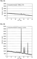
FIGS. 3A and 3B are the results of the XRD measurement to the precursors obtained in Examples 1 and 2. -
FIGS. 4A to 4C are the results of the XRD measurement to the precursors obtained in Examples 3 to 5. -
FIGS. 5A and 5B are the results of the XRD measurement to the precursors obtained in Comparative Examples 1 and 2. -
FIG. 6 is the result of the XRD measurement to the precursor obtained in Comparative Example 4. -
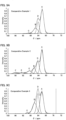
FIGS. 7A and 7B are the results of the NMR measurement to the sulfide solid electrolytes obtained in Examples 1 and 2. -
FIGS. 8A and 8B are the results of the NMR measurement to the sulfide solid electrolytes obtained in Examples 3 and 4. -
FIGS. 9A to 9C are the results of the NMR measurement to the sulfide solid electrolytes obtained in Comparative Examples 1 to 3. - The sulfide solid electrolyte, the precursor of the sulfide solid electrolyte, the all solid state battery and the method for producing the sulfide solid electrolyte in the present invention will be hereinafter described in detail.
- The sulfide solid electrolyte in the present invention comprises a Li element, an M element (M is at least one kind of P, Ge, Si and Sn), and a S element. Further, the sulfide solid electrolyte has an argyrodite type crystal phase. Also, in 31P-MAS-NMR, the sulfide solid electrolyte has peak A at 82.1 ppm ± 0.5 ppm and peak B at 86.1 ppm ± 0.5 ppm, and when an area ratio of the peak A is regarded as SA, and an area ratio of the peak B is regarded as SB, a proportion of the SB to the SA, that is SB/SA, is the specific value or less.
- According to the present invention, since SB/SA is low, a sulfide solid electrolyte with high ion conductivity may be obtained. As described later, peak A is a peak deriving from the argyrodite type crystal phase, and peak B is a peak deriving from an amorphous phase related to the argyrodite type crystal phase.
- Here, as a method for synthesizing a sulfide solid electrolyte having the argyrodite type crystal phase, a method wherein a sulfide glass is produced by milling a raw material composition, and then, the sulfide glass is burned, is conventionally know.
- From the detailed investigation by the present inventor regarding the relationship between the amorphous property of a sulfide glass and the ion conductivity of a sulfide solid electrolyte obtained by burning the sulfide glass, it was found out that, when the amorphous property of the sulfide glass is too high, the amorphous phase tends to remain in the obtained sulfide solid electrolyte so that the ion conductivity is not sufficiently improved. Similarly, it was found out that, when the amorphous property of the sulfide glass is too low, uniform solid-phase reaction hardly occurs during burning so that an argyrodite type crystal phase with high ion conductivity is hardly deposited. So, by producing a precursor by moderately amorphizing the raw material composition and burning the precursor, a sulfide solid electrolyte with little remaining amorphous phase could be obtained. As described above, in the present invention, since SB/SA is low, a sulfide solid electrolyte with high ion conductivity may be obtained.
-
Patent Literature 1, for example, discloses in Example thereof that mechanical milling was carried out under conditions of 370 rpm for 25 hours. As described in the later described Comparative Example 4, it was suggested that SB/SA was high since Li2S residual ratio was low and the amorphization was progressed. Also,Patent Literature 2, for example, discloses in Example thereof that a crushing and mixing was carried out for 15 hours with a ball mill; however, since the rotation speed of the ball mill is not known, it is difficult to compare directly. Also, althoughPatent Literature 2 discloses in [0027] "therefore, pulverization and mixing to the extent that crystallinity of the raw material powders can be maintained is desirable", it is difficult to compare quantitatively, since it is not clear whether "crystallinity of the raw material powders" indicates the crystallinity of the all raw material powders, or the crystallinity of a part of the raw material powder. In the first place, an object ofPatent Literature 2 is to prevent sulfur defects at the time of calcination, and the object is different from that of the present invention. - The sulfide solid electrolyte in the present invention comprises a Li element, an M element (M is at least one kind of P, Ge, Si and Sn), and a S element. The sulfide solid electrolyte may further comprise an X element (X is a halogen).
- The sulfide solid electrolyte has an argyrodite type crystal phase. The argyrodite type crystal phase in the sulfide solid electrolyte may be confirmed by an X-ray diffraction (XRD) measurement. The sulfide solid electrolyte preferably has a peak at 2θ = 15.6° ± 0.5°, 18.1° ± 0.5°, 25.7° ± 0.5°, 30.2° ± 0.5°, and 31.6° ± 0.5° in an X-ray diffraction (XRD) measurement using a CuKα ray. These peaks are typical peaks of the argyrodite type crystal phase. The sulfide solid electrolyte preferably has the argyrodite type crystal phase as a main phase.
- The sulfide solid electrolyte has peak A at 82.1 ppm ± 0.5 ppm and peak B at 86.1 ppm ± 0.5 ppm in 31P-MAS-NMR. Peak A is a peak deriving from the argyrodite type crystal phase, and peak B is a peak deriving from an amorphous phase related to the argyrodite type crystal phase. Also, when an area ratio of the peak A is regarded as SA, and an area ratio of the peak B is regarded as SB, a proportion of the SB to the SA, that is SB/SA, is preferably low. The reason is because the ion conductivity of the crystal phase is higher than the amorphous phase. SB/SA is usually 0.23 or less. Meanwhile, SB/SA may be 0, and may be more than 0. In the latter case, SB/SA may be 0.16 or more.
- SA is preferably high. SA is, for example, 50% or more, may be 51.8% or more, and may be 55.6% or more. Meanwhile, SA is, for example, 65% or less, and may be 60.1% or less. SB is preferably low. SB is, for example, 15% or less, and may be 13.2% or less. Meanwhile, SB may be 0%, and may be more than 0%. In the latter case, SB may be 9.6% or more.
- The sulfide solid electrolyte may further have peak C at 89.1 ppm ± 0.5 ppm, and may not have peak C. When the proportion of the X element included in the sulfide solid electrolyte is high, for example, the peak C tends to appear, although the improvement of the ion conductivity may be expected. When an area ratio of the peak C is regarded as SC, a proportion of a total of the SB and the SC to the SA, that is (SB + SC)/SA, is preferably low. (SB + SC)/SA is, for example, 0.27 or less, and may be 0.24 or less. Meanwhile, (SB + SC)/SA is, for example, 0.05 or more, and may be 0.18 or more. The SC is preferably low. The SC is, for example, 2.1% or less, and may be 1.1% or less. Meanwhile, SC may be 0%, and may be more than 0%. In the latter case, SC may be 0.7% or more.
- The sulfide solid electrolyte may further have peak D at 84.1 ppm ± 0.5 ppm, and may not have peak D. When the area ratio of the peak D is regarded as SD, the SD is, for example, 1% or more, and may be 10% or more. Meanwhile, SD is, for example, 35% or less.
- The sulfide solid electrolyte in the present invention comprises a Li element, an M element (M is at least one kind of P, Ge, Si and Sn), and a S element. The M element may be one kind, and may be two kinds or more. The sulfide solid electrolyte preferably comprises at least P element as the M element. Also, the sulfide solid electrolyte may further comprise an X element (X is a halogen), and may not comprise the X element. Examples of the X element may include a F element, a Cl element, a Br element and an I element. The X element may be one kind, and may be two kinds or more. The sulfide solid electrolyte preferably comprises at least a Cl element as the X element. When the sulfide solid electrolyte comprises two kinds or more of the X element, the proportion of Cl element to all the X elements is, for example, 50 mol% or more, may be 70 mol% or more, and may be 90 mol% or more.
- Also, peak A and peak B in 31P-MAS-NMR are caused by the argyrodite type crystal phase. Therefore, the composition of the sulfide solid electrolyte is not particularly limited as long as the composition is able to give such an argyrodite type crystal phase. Examples of the composition of the sulfide solid electrolyte may include Li7-yPS6-yXy (y satisfies 0 ≤ y ≤ 2). The y may be 0, and may be more than 0. In the latter case, the y may be 0.5 or more, may be 1.0 or more, may be 1.2 or more, and may be 1.4 or more. As the y increases, the ion conductivity of the sulfide solid electrolyte also increases. Meanwhile the y is usually 2 or less, may be 1.8 or less, may be 1.7 or less, and may be 1.6 or less. When the y is too high, a crystal phase (different phase) with low ion conductivity is likely to occur.
- The ion conductivity of the sulfide solid electrolyte is preferably high. The ion conductivity at 25°C is, for example, 7 mS/cm or more, may be 8 mS/cm or more, and may be 9 mS/cm or more.
- Examples of the shape of the sulfide solid electrolyte may include a granular shape. Also, the average particle size (D50) of the sulfide solid electrolyte is, for example, 0.1 µm or more and 50 µm or less. The average particle size (D50) may be determined from the result of a particle size distribution measurement by a laser diffraction scattering method. A use application of the sulfide solid electrolyte is not particularly limited, and is preferably used for, for example, an all solid state battery.
- The precursor of the sulfide solid electrolyte in the present invention is a precursor of the above described sulfide solid electrolyte, and the Li2S residual ratio thereof is in a specific range.
- According to the present invention, since the Li2S residual ratio is in the specific range, a precursor that enables to obtain a sulfide solid electrolyte with high ion conductivity may be obtained.
- The constituent element, composition, and other matters of the precursor may be in the same contents as those described in "A. Sulfide solid electrolyte" above; thus, the descriptions herein are omitted.
- The Li2S residual ratio is 7.7% or more, may be 23.3% or more. When the Li2S residual ratio is too low, an amorphous phase is likely to be remained in the sulfide solid electrolyte obtained by burning the precursor. As the result, there is a possibility that the ion conductivity is not sufficiently improved. Meanwhile, the Li2S residual ratio of the precursor is 54.7% or less, and may be 34.2% or less. When the Li2S residual ratio is too high, uniform solid-phase reaction hardly occurs during burning so that an argyrodite type crystal phase with high ion conductivity is hardly deposited. As the result, there is a possibility that the ion conductivity is not sufficiently improved. A method for calculating the Li2S residual ratio will be described in Examples described later.
- When an X-ray diffraction (XRD) measurement using a CuKα ray is carried out, the precursor usually has a peak of Li2S. Also, the precursor may or may not have a peak of LiX (X is a halogen). Examples of LiX may include LiF, LiCl, LiBr and LiI. Also, the precursor may or may not have a peak of P2S5. Incidentally, the precursor does not usually have the argyrodite type crystal phase; however, the argyrodite type crystal phase occurs by burning.
- The precursor of the sulfide solid electrolyte is preferably used for obtaining the sulfide solid electrolyte described in "A. Sulfide solid electrolyte" above.
-
FIG. 1 is a schematic cross-sectional view showing an example of the all solid state battery. Allsolid state battery 10 shown inFIG. 1 comprisescathode layer 1 including a cathode active material,anode layer 2 including an anode active material,solid electrolyte layer 3 formed betweencathode layer 1 andanode layer 2, cathodecurrent collector 4 for collecting currents ofcathode layer 1, anodecurrent collector 5 for collecting currents ofanode layer 2, andbattery case 6 that houses these members. Further, at least one ofcathode layer 1,anode layer 2 andsolid electrolyte layer 3 includes the sulfide solid electrolyte described in "A. Sulfide solid electrolyte" above. - An all solid state battery with high output property may be obtained by using the above described sulfide solid electrolyte.
- The cathode layer is a layer including at least a cathode active material. The cathode layer may include at least one of a solid electrolyte, a conductive material and a binder, in addition to the cathode active material.
- Examples of the cathode active material may include an oxide active material. Specific examples of the oxide active material may include rock salt bed type active materials such as LiCoO2, LiMnO2, LiNiO2, LiVO2, LiNi1/3Co1/3Mn1/3O2; spinel type active materials such as LiMn2O4, and Li(Ni0.5Mn1.5) O4; and olivine type active materials such as LiFePO4, LiMnPO4, LiNiPO4, and LiCuPO4.
- The surface of the cathode active material may be coated with a coating layer. The reason therefor is to inhibit the reaction of the cathode active material with the sulfide solid electrolyte. Examples of the material for the coating layer may include Li ion conductive oxides such as LiNbO3, Li3PO4, and LiPON. The average thickness of the coating layer is, for example, 1 nm or more and 20 µm or less, and may be 1 nm or more and 10 nm or less.
- The cathode layer preferably includes the above described sulfide solid electrolyte. Also, examples of the conductive material may include a carbon material. Examples of the carbon material may include particulate carbon materials such as acetylene black (AB) and Ketjen black (KB); and fibrous carbon materials such as carbon fiber, carbon nanotube (CNT), and carbon nanofiber (CNF). Examples of the binder may include fluorine-based binders such as polyvinylidene fluoride (PVDF). The thickness of the cathode layer is, for example, 0.1 µm or more and 1000 µm or less.
- The solid electrolyte layer is a layer including at least a solid electrolyte. Also, the solid electrolyte layer may include a binder, in addition to the solid electrolyte. The solid electrolyte and the binder are similar to those described above. The solid electrolyte layer preferably includes the above described sulfide solid electrolyte. The thickness of the solid electrolyte layer is, for example, 0.1 µm or more and 1000 µm or less.
- The anode layer is a layer including at least an anode active material. Also, the anode layer may include at least one of a solid electrolyte, a conductive material and a binder, in addition to the anode active material.
- Examples of the anode active material may include a metal active material and a carbon active material. Examples of the metal active material may include In, Al, Si, and Sn. Meanwhile, examples of the carbon active material may include mesocarbon microbead (MCMB), highly oriented pyrolytic graphite (HOPG), hard carbon, and soft carbon.
- The solid electrolyte, the conductive material and the binder are similar to those described above. The anode layer preferably includes the above described sulfide solid electrolyte. The thickness of the anode layer is, for example, 0.1 µm or more and 1000 µm or less.
- The all solid state battery usually comprises a cathode current collector for collecting currents of the cathode active material and an anode current collector for collecting currents of the anode active material. Examples of the materials for the cathode current collector may include SUS, aluminum, nickel, iron, titanium, and carbon. Meanwhile, examples of the materials for the anode current collector may include SUS, copper, nickel, and carbon. Also, for a battery case, a common battery case such as a battery case made from SUS may be used.
- The all solid state battery is preferably an all solid state lithium ion battery. Also, the all solid state battery may be a primary battery, and may be a secondary battery. Among the above, the secondary battery is preferable, so as to be repeatedly charged and discharged, and is useful as, for example, a car-mounted battery. Incidentally, the secondary battery includes the use of a secondary battery as a primary battery (use for the purpose of only one discharge, after charge). Also, examples of the shape of the all solid state battery may include a coin shape, a laminate shape, a cylindrical shape, and a square shape.
-
FIG. 2 is a flow chart showing an example of the method for producing the sulfide solid electrolyte in the present invention. InFIG. 2 , a raw material composition including Li2S, P2S5, and LiX (X is a halogen) is prepared. Next, the raw material composition is mixed by, for example, mechanical milling, and a precursor with Li2S residual ratio in a specific range is obtained. Next, the obtained precursor is burned. Thereby, the sulfide solid electrolyte described in "A. Sulfide solid electrolyte" above is obtained. - According to the present invention, a sulfide solid electrolyte with high ion conductivity may be obtained by using the precursor wherein the Li2S residual ratio is in the specific range.
- The mixing step is a step of obtaining a precursor with Li2S residual ratio in the specific range, by mixing a raw material composition including at least Li2S.
- The raw material composition of the sulfide solid electrolyte includes a Li element, an M element (M is at least one kind of P, Ge, Si and Sn), and a S element. The raw material composition may further include an X element (X is a halogen). Examples of the raw material including an Li element may include a Li sulfide. The raw material composition usually includes Li2S as the Li sulfide. Examples of the raw material including the M element may include a sulfide including the M element. Examples of the sulfide including the M element may include P2S5, GeS2, SiS2 and SnS2. Examples of the raw material including the X element may include a lithium halide. Examples of the lithium halide may include LiF, LiCl, LiBr and LiI. Examples of the raw material including a S element may include the above described sulfides and a simple substance of sulfur.
- In the mixing step, the raw material composition is mixed and the precursor wherein the Li2S residual ratio is in the specific range is obtained. That is, the precursor is obtained by moderately amorphizing the raw material composition by mixing. Examples of a method for mixing the raw material composition include mechanical milling such as ball milling and vibration milling. The mechanical milling may be a dry-type and may be a wet-type; the latter is preferable from the viewpoint of uniform treatment. The kind of the dispersing medium used for the wet-type mechanical milling is not particularly limited.
- The various conditions for the mechanical milling are set so as to obtain the desired precursor. When planetary ball milling is used, for example, the raw material mixture and balls for crushing are added, and the treatment is conducted at a specific rotation number for a specific time. The weighing table rotation number of the planetary ball milling is, for example, 150 rpm or more. Meanwhile, the weighing table rotation number of the planetary ball milling is, for example, 500 rpm or less, and may be 250 rpm or less. Also, the treatment time of the planetary ball milling is, for example, 5 minutes or more, and may be 10 minutes or more. Meanwhile, the treatment time of the planetary ball milling is, for example, 15 hours or less, may be 12 hours or less, and may be 10 hours or less.
- The precursor obtained by the mixing step may be in the same contents as those described in "B. Precursor of sulfide solid electrolyte" above; thus, the descriptions herein are omitted.
- The burning step is a step of burning the precursor.
- The burning temperature is preferably, for example, higher than 400°C, may be 450°C or more, and may be 480°C or more. Meanwhile, the burning temperature is, for example, 800°C or less. The burning time is, for example, 1 hour or more, and may be 2 hours or more. Meanwhile, the burning time is, for example, 10 hours or less, and may be 5 hours or less. Examples of a burning atmosphere may include an inert gas atmosphere and a vacuum.
- The sulfide solid electrolyte obtained by the above described steps may be in the same contents as those described in "A. Sulfide solid electrolyte" above; thus, the descriptions herein are omitted.
- Incidentally, the present invention is not limited to the embodiments.
- A raw material composition (composition: Li5.4PS4.4Cl1.6) was obtained by weighing 0.6557 g of Li2S (from Furuuchi Chemical Corporation), 0.8348 g of P2S5 (from Aldrich Co. LLC) and 0.5095 g of LiCl (from Kojundo Chemical Lab. Co., Ltd.). The obtained raw material composition was projected into a zirconia pot (45 ml) together with zirconia balls of 5 mm diameter, then, 4 g of dehydrated heptane (from Kanto Chemical Industry Co., Ltd.) was projected, and the pot was sealed. The sealed pot was set to a planetary ball milling machine (P-7 from Fritsch Japan Co., Ltd), mechanically milled for 15 hours at 500 rpm, and a precursor of a sulfide solid electrolyte was obtained.
- The obtained precursor was molded into pellets, projected into a carbon coated quartz tube, vacuum sealed, burned at 500°C for 3 hours (temperature increasing rate of 1°C/min), crushed and mixed in a mortar, and thereby, a sulfide solid electrolyte was obtained.
- A precursor of a sulfide solid electrolyte was obtained in the same manner as in Comparative Example 1 except that the conditions for the mechanical milling were changed to 200 rpm for 10 minutes. A sulfide solid electrolyte was obtained in the same manner as in Comparative Example 1 except that the obtained precursor was used.
- A precursor of a sulfide solid electrolyte was obtained in the same manner as in Comparative Example 1 except that the conditions for the mechanical milling were changed to 200 rpm for 30 minutes. A sulfide solid electrolyte was obtained in the same manner as in Comparative Example 1 except that the obtained precursor was used.
- A precursor of a sulfide solid electrolyte was obtained in the same manner as in Comparative Example 1 except that the conditions for the mechanical milling were changed to 200 rpm for 60 minutes. A sulfide solid electrolyte was obtained in the same manner as in Comparative Example 1 except that the obtained precursor was used.
- A precursor of a sulfide solid electrolyte was obtained in the same manner as in Comparative Example 1 except that the conditions for the mechanical milling were changed to 500 rpm for 10 hours. A sulfide solid electrolyte was obtained in the same manner as in Comparative Example 1 except that the obtained precursor was used.
- A precursor of a sulfide solid electrolyte was obtained in the same manner as in Comparative Example 1 except that the conditions for the mechanical milling were changed to 200 rpm for 15 hours. A sulfide solid electrolyte was obtained in the same manner as in Comparative Example 1 except that the obtained precursor was used.
- A precursor of a sulfide solid electrolyte was obtained in the same manner as in Comparative Example 1 except that, instead of the mechanical milling, the raw material composition was mixed in a mortar so as to be even. A sulfide solid electrolyte was obtained in the same manner as in Comparative Example 1 except that the obtained precursor was used.
- A sulfide solid electrolyte was obtained in the same manner as in Comparative Example 1 except that the burning temperature was changed to 400°C for 3 hours.
- A precursor of a sulfide solid electrolyte was obtained in the same manner as in Comparative Example 1 except that the conditions for the mechanical milling were changed to 370 rpm for 25 hours. A sulfide solid electrolyte was obtained in the same manner as in Comparative Example 1 except that the obtained precursor was used.
- An X-ray diffraction (XRD) measurement using a CuKα ray was carried out for precursors obtained in Examples 1 to 5 and Comparative Examples 1, 2 and 4. The results are shown in
FIGS 3A to 5B . As shown inFIG. 3A , the peaks of Li2S were confirmed in Example 1 in the vicinity of 2θ = 27.0° and in the vicinity of 2θ = 31.2°. Also, in Example 1, the peaks of LiCl were confirmed in the vicinity of 2θ = 30.0° and in the vicinity of 2θ = 34.8°. Also, as shown inFIG. 3B andFIG. 4A to FIG. 4C , the peaks of Li2S and the peaks of LiCl were confirmed also in Examples 2 to 5, as similar to Example 1. - Meanwhile, as shown in
FIG. 5A , although the peaks of Li2S and the peaks of LiCl were confirmed in Comparative Example 1, these peaks were broad compared to the peaks in Examples 2 to 5, and it was confirmed that the amorphization has been progressed. Also, as shown inFIG. 5B , the peaks of Li2S and the peaks of LiCl were confirmed in Comparative Example 2. Particularly in Comparative Example 2, extremely large peak was confirmed in the vicinity of 2θ = 27.0°. Also, as shown inFIG. 6 , it was confirmed that the amorphization has been progressed also in Comparative Example 4, as similar to Comparative Example 1. Also, the intensity of the peak of Li2S (the peak at 2θ = 27.0° ± 0.5°) in Comparative Example 2 was regarded as 100%, the intensity of the peak of Li2S in Examples 1 to 5 and Comparative Example 1 was determined as Li2S residual ratio. The results are shown in Table 1. Incidentally, the peak of P2S5 was confirmed in the vicinity of 2θ = 25.6° in Comparative Example 2. Meanwhile, although the peak of P2S5 was confirmed in the vicinity of 2θ = 25.6° also in Example 1, the intensity was decreased. - 31P-MAS-NMR measurement was carried out for the sulfide solid electrolytes obtained in Examples 1 to 4 and Comparative Examples 1 to 3. The measuring conditions were as described below.
- Equipment: INOVA 300 (from Agilent Technologies, Inc.)
- Test tube: 7mmφ ZrO2 rotor
- Rotation speed: 7000 Hz
- Standard: phosphoric acid = 0 ppm
- Cumulated number: 100 to 500 Gain = auto
- Repetition time: 10 seconds
- The results are shown in
FIG. 7A to FIG. 9C . Incidentally, although the sulfide solid electrolyte is a material whose relaxation time is short, the repetition time is preferably, for example, 8 seconds or more. When the repetition time is too short, sufficient relaxation may not be obtained, and the waveform tends to be disturbed. Meanwhile, the repetition time is, for example, 15 seconds or less. - As shown in
FIG. 7A to FIG. 9C , the following peaks A to D were confirmed in Examples 1 to 4 and Comparative Examples 1 to 3. - Peak A: 82.1 ± 0.5 ppm
- Peak B: 86.1 ± 0.5 ppm
- Peak C: 89.1 ± 0.5 ppm
- Peak D: 84.1 ± 0.5 ppm
- Peak A is a peak deriving from the argyrodite type crystal phase. Peak B is a peak deriving from an amorphous phase related to the argyrodite type crystal phase. Meanwhile, peak C is presumed to be a peak deriving from the crystal phase other than the argyrodite type crystal phase (different phase), and peak D is presumed to be a peak deriving from P-S bonding in the vicinity of the site where Cl is not dissolved in the argyrodite type crystal phase.
- In Examples 1 to 4 and Comparative Examples 1 and 3, only peaks A to D were confirmed and other peak was not confirmed in a range of 76 ppm or more and 100 ppm or less. In contrast to this, in addition to peaks A to D, peaks E and F were confirmed in Comparative Example 2, in a range of 76 ppm or more and 100 ppm or less. Also, as shown in
FIG. 7A to FIG. 9C , the area ratio of peak A to D was determined by carrying out a waveform separation for the obtained NMR chart, by fitting in a state where each peak top is fixed so as to be in the designated range. The results are shown in Table 1. - The ion conductivity (25°C) of the sulfide solid electrolytes obtained in Examples 1 to 5 and Comparative Examples 1 to 4 was measured. 100 mg of the obtained sulfide solid electrolyte powder was pressed under pressure of 6 ton/cm2 with a pelleting press so as to produce a pellet. The resistance of the pellet was determined by an AC impedance method, and the ion conductivity was determined from the thickness of the pellet. The results are shown in Table 1.
[Table 1] Li2S residual ratio (%) NMR Ion conductivity (mS/cm) Area ratio of peak A SA(%) Area ratio of peak B SB (%) Area ratio of peak C SC (%) Area ratio of peak D SD (%) SB/SA (SB+SC)/SA Example 1 54.7 51.8 11.9 2.0 34.3 0.23 0.27 7.1 Example 2 34.2 55.6 12.8 0.7 30.9 0.23 0.24 96 Example 3 23.3 60.1 9.6 1.1 29.2 0.16 0.18 9.9 Example 4 7.7 56.5 13.2 2.1 28.1 0.23 0.27 7.2 Example 5 18.9 - - - - - - 8.9 Comp. Ex. 1 3.3 58.0 18.8 1.4 21.7 0.32 0.35 5.5 Comp. Ex. 2 100 54.0 13.4 9.5 23.4 0.25 0.42 4.9 Comp. Ex. 3 3.3 42.7 26.1 1.1 30.1 0.61 0.64 3.9 Comp. Ex. 4 4.3 - - - - - - 6.3 - As shown in Table 1, the ion conductivity was higher in Examples 1 to 5, compared to Comparative Examples 1 to 4. The ion conductivity in Examples 2 and 3 was 9 mS/cm or more, and the ion conductivity was particularly high. Also, in Examples 1 to 5, the Li2S residual ratio in the precursor was 7.7% or more and 54.7% or less, higher than Comparative Example 1. As described above, it was confirmed that a sulfide solid electrolyte with high ion conductivity may be obtained by making the Li2S residual ratio high to an extent.
- Also, from the MNR results, it was suggested that the area ratio of peaks A to C and the ion conductivity of the sulfide solid electrolyte were mutually related. Comparing Examples 1 to 4, for example, a tendency was suggested that, the higher the area ratio of peak A SA was, the higher the ion conductivity was. Also, comparing Example 3 and Comparative Example 1, a tendency was suggested that, the lower the area ratio of peak B SB was, the higher the ion conductivity was, although the area ratios of peak A SA and peak C SC were almost the same. Also, comparing Example 2 and Comparative Example 2, a tendency was suggested that, the lower the area ratio of peak C SC was, the higher the ion conductivity was, although the area ratios of peak A SA and peak B SB were almost the same. As described above, the lower SB/SA or (SB + SC) /SA was, the higher the ion conductivity was.
- Also, comparing Comparative Example 1 (burning temperature 500°C) and Comparative Example 3 (burning temperature 400°C), the area ratio SA was higher and the area ratio SB was lower in Comparative Example 1 than Comparative Example 3. As described above, it was suggested that, in order to make the area ratio SA higher, relatively high burning temperature was preferable. Also, although the mechanical milling conditions in Comparative Example 4 (370 rpm, 25 hours) were the same as the mechanical milling conditions in Example in
Patent Literature 1, the Li2S residual ratio was low so that it was suggested that SB/SA was high since the amorphization was progressed. - A raw material composition (composition: Li5.8PS4.8Cl1.2) was obtained by weighing 0.7896 g of Li2S (from Furuuchi Chemical Corporation), 0.8304 g of P2S5 (from Aldrich Co. LLC) and 0.3801 g of LiCl (from Kojundo Chemical Lab. Co., Ltd.). A sulfide solid electrolyte was obtained in the same manner as in Comparative Example 3 except that the obtained raw material composition was used.
- A raw material composition (composition: Li5.6PS4.6Cl1.4) was obtained by weighing 0.7228 g of Li2S (from Furuuchi Chemical Corporation), 0.8326 g of P2S5 (from Aldrich Co. LLC) and 0.4446 g of LiCl (from Kojundo Chemical Lab. Co., Ltd.). A sulfide solid electrolyte was obtained in the same manner as in Comparative Example 3 except that the obtained raw material composition was used.
- A raw material composition (composition: Li5.2PS4.2Cl1.8) was obtained by weighing 0.5883 g of Li2S (from Furuuchi Chemical Corporation), 0.8370 g of P2S5 (from Aldrich Co. LLC) and 0.5747 g of LiCl (from Kojundo Chemical Lab. Co., Ltd.). A sulfide solid electrolyte was obtained in the same manner as in Comparative Example 3 except that the obtained raw material composition was used.
- A raw material composition (composition: Li5.0PS4.0Cl2.0) was obtained by weighing 0.5205 g of Li2S (from Furuuchi Chemical Corporation), 0.8393 g of P2S5 (from Aldrich Co. LLC) and 0.6403 g of LiCl (from Kojundo Chemical Lab. Co., Ltd.). A sulfide solid electrolyte was obtained in the same manner as in Comparative Example 3 except that the obtained raw material composition was used.
- 31P-MAS-NMR measurement was carried out for the sulfide solid electrolytes obtained in Reference Examples 1 to 4. The measuring conditions were the same as described above. The results are shown in Table 2.
[Table 2] y in Li7-yPS6-yCly NMR Area ratio of peak A SA(%) Area ratio of peak B SB (%) Area ratio of peak C SC (%) Area ratio of peak D SD (%) SB/SA (SB+SC)/SA Ref. Ex. 1 1.2 20.5 55.1 0.0 24.4 2.69 1.19 Ref. Ex. 2 1.4 27.5 46.0 0.0 26.5 1.67 0.96 Ref. Ex. 3 1.8 21.6 52.7 6.6 17.2 2.44 1.10 Ref. Ex. 4 2.0 18.3 14.6 33.6 15.1 0.80 2.66 - As shown in Table 2, it was confirmed that as y got lager, the area ratio of peak C became higher in Reference Examples 1 to 4. Therefore, it was suggested that peak C was a different phase related to Cl not dissolved in the argyrodite type crystal phase. Therefore, in the viewpoint of preventing the deposition of a different phase, it was suggested that y was preferably 1.8 or less. Also, the area ratio of peak C in Reference Examples 1 and 2 was 0 %. Therefore, it was suggested that peak C did not appear when the value of y was low.
-
- 1
- cathode layer
- 2
- anode layer
- 3
- solid electrolyte layer
- 4
- cathode current collector
- 5
- anode current collector
- 6
- battery case
- 10
- all solid state battery
Claims (7)
- A method for producing a sulfide solid electrolyte, wherein the sulfide solid electrolyte comprises:a Li element,an M element (M is at least one kind of P, Ge, Si and Sn), anda S element, andthe sulfide solid electrolyte has an argyrodite type crystal phase,in 31P-MAS-NMR, the sulfide solid electrolyte haspeak A at 82.1 ppm ± 0.5 ppm andpeak B at 86.1 ppm ± 0.5 ppm, andwhen an area ratio of the peak A is regarded as SA, and an area ratio of the peak B is regarded as SB, a proportion of the SB to the SA, that is SB/SA, is 0.23 or less, whereinthe measuring conditions of 31P-MAS-NMR are as described in the description, andwherein the method comprises the steps of:a mixing step of obtaining a precursor with a Li2S residual ratio of 7.7% or more and 54.7% or less, by mixing a raw material composition including at least Li2S, anda burning step of burning the precursor, whereinthe Li2S residual ratio is determined according to the method disclosed in the description,the method for mixing the raw material composition includes mechanical milling, andthe burning temperature is between 400 and 800 °C.
- The method for producing the sulfide solid electrolyte according to claim 1, characterized in that the sulfide solid electrolyte further has peak C at 89.1 ppm ± 0.5 ppm, and
when an area ratio of the peak C is regarded as SC, a proportion of a total of the SB and the SC to the SA, that is (SB + SC) /SA, is 0.27 or less. - The method for producing the sulfide solid electrolyte according to claim 1 or 2, characterized in that the sulfide solid electrolyte further has peak D at 84.1 ppm ± 0.5 ppm.
- The method for producing the sulfide solid electrolyte according to any one of claims 1 to 3, characterized in that the M includes at least P.
- The method for producing the sulfide solid electrolyte according to any one of claims 1 to 4, characterized in that the sulfide solid electrolyte further comprises an X element (X is a halogen).
- The method for producing the sulfide solid electrolyte according to claim 5, characterized in that the X includes at least Cl.
- The method for producing the sulfide solid electrolyte according to claim 5 or 6, characterized in that the sulfide solid electrolyte has a composition represented by Li7-yPS6-yXy (y satisfies 0 < y ≤ 2) .
Applications Claiming Priority (2)
| Application Number | Priority Date | Filing Date | Title |
|---|---|---|---|
| JP2019063867 | 2019-03-28 | ||
| JP2020041049A JP7318569B2 (en) | 2019-03-28 | 2020-03-10 | Sulfide solid electrolyte, precursor of sulfide solid electrolyte, all-solid battery, and method for producing sulfide solid electrolyte |
Publications (2)
| Publication Number | Publication Date |
|---|---|
| EP3716389A1 EP3716389A1 (en) | 2020-09-30 |
| EP3716389B1 true EP3716389B1 (en) | 2025-04-09 |
Family
ID=70008324
Family Applications (1)
| Application Number | Title | Priority Date | Filing Date |
|---|---|---|---|
| EP20165577.6A Active EP3716389B1 (en) | 2019-03-28 | 2020-03-25 | Sulfide solid electrolyte, precursor of sulfide solid electrolyte, all solid state battery and method for producing sulfide solid electrolyte |
Country Status (4)
| Country | Link |
|---|---|
| US (1) | US11575151B2 (en) |
| EP (1) | EP3716389B1 (en) |
| KR (1) | KR102378488B1 (en) |
| CN (1) | CN111755740B (en) |
Families Citing this family (4)
| Publication number | Priority date | Publication date | Assignee | Title |
|---|---|---|---|---|
| CN113410515B (en) * | 2021-06-25 | 2022-08-12 | 高能时代(珠海)新能源科技有限公司 | A kind of sulfide solid electrolyte and preparation method and application |
| CN113497270A (en) * | 2021-07-05 | 2021-10-12 | 西北师范大学 | Preparation and application of Cl-doped lithium tin phosphorus sulfur solid electrolyte |
| JP7476867B2 (en) * | 2021-11-22 | 2024-05-01 | トヨタ自動車株式会社 | Sulfide solid electrolyte, battery, and method for producing sulfide solid electrolyte |
| CN114709474B (en) * | 2022-04-28 | 2023-07-11 | 上海屹锂新能源科技有限公司 | Bismuth-doped sulfur silver germanium ore type sulfide solid electrolyte and preparation method thereof |
Family Cites Families (9)
| Publication number | Priority date | Publication date | Assignee | Title |
|---|---|---|---|---|
| JP6234665B2 (en) * | 2011-11-07 | 2017-11-22 | 出光興産株式会社 | Solid electrolyte |
| JP6044587B2 (en) * | 2014-05-15 | 2016-12-14 | トヨタ自動車株式会社 | Sulfide solid electrolyte material, battery, and method for producing sulfide solid electrolyte material |
| JP5873533B2 (en) * | 2014-07-16 | 2016-03-01 | 三井金属鉱業株式会社 | Sulfide-based solid electrolyte for lithium-ion battery |
| EP3240089B1 (en) * | 2014-12-26 | 2019-04-24 | Mitsui Mining and Smelting Co., Ltd. | Sulfide-based solid electrolyte for lithium ion cell, and solid electrolyte compound |
| JP6352960B2 (en) * | 2016-02-09 | 2018-07-04 | 国立大学法人東京工業大学 | Sulfide solid electrolyte material, battery, and method for producing sulfide solid electrolyte material |
| CN109526242B (en) * | 2016-08-10 | 2022-04-15 | 出光兴产株式会社 | Sulfide solid electrolyte |
| JP6945382B2 (en) | 2016-09-08 | 2021-10-06 | 出光興産株式会社 | Sulfide solid electrolyte |
| KR102428981B1 (en) * | 2016-11-16 | 2022-08-03 | 이데미쓰 고산 가부시키가이샤 | sulfide solid electrolyte |
| WO2018096957A1 (en) * | 2016-11-28 | 2018-05-31 | 国立研究開発法人産業技術総合研究所 | Inorganic sulfide and method for producing same |
-
2020
- 2020-03-25 EP EP20165577.6A patent/EP3716389B1/en active Active
- 2020-03-25 US US16/829,018 patent/US11575151B2/en active Active
- 2020-03-25 KR KR1020200036357A patent/KR102378488B1/en active Active
- 2020-03-26 CN CN202010222591.2A patent/CN111755740B/en active Active
Also Published As
| Publication number | Publication date |
|---|---|
| KR102378488B1 (en) | 2022-03-25 |
| US11575151B2 (en) | 2023-02-07 |
| US20200313234A1 (en) | 2020-10-01 |
| KR20200115295A (en) | 2020-10-07 |
| CN111755740A (en) | 2020-10-09 |
| CN111755740B (en) | 2023-12-05 |
| EP3716389A1 (en) | 2020-09-30 |
Similar Documents
| Publication | Publication Date | Title |
|---|---|---|
| KR101300304B1 (en) | Multi-element lithium phosphate compound particles having olivine structure, method for producing same, and lithium secondary battery using same in positive electrode material | |
| CN111279528B (en) | Positive electrode active material for nonaqueous electrolyte secondary battery, method for producing same, positive electrode composite material paste, and nonaqueous electrolyte secondary battery | |
| US9077044B2 (en) | Anode material | |
| EP2203948B1 (en) | Positive electrode active material, lithium secondary battery, and manufacture methods therefore | |
| US9960413B2 (en) | LMFP cathode materials with improved electrochemical performance | |
| EP3731315A1 (en) | Negative electrode material for lithium ion secondary battery, and method of manufacturing negative electrode material for lithium ion secondary battery | |
| EP3716389B1 (en) | Sulfide solid electrolyte, precursor of sulfide solid electrolyte, all solid state battery and method for producing sulfide solid electrolyte | |
| EP3483971A1 (en) | All-solid-state lithium ion battery | |
| KR101972187B1 (en) | Structurally stable active material for battery electrodes | |
| JP7159639B2 (en) | Method for producing particles of transition metal composite hydroxide, and method for producing positive electrode active material for lithium ion secondary battery | |
| EP3694034B1 (en) | Anode layer and all solid state battery | |
| EP3896758A1 (en) | Negative electrode carbon material for lithium ion secondary battery, production method therefor, and negative electrode and lithium ion secondary battery using same | |
| EP3694035A1 (en) | Anode layer and all solid state battery | |
| EP4007013B1 (en) | Negative electrode material for nonaqueous electrolyte secondary batteries, and nonaqueous electrolyte secondary battery | |
| EP3442058B1 (en) | Cathode mixture and method for producing the same | |
| JP7318569B2 (en) | Sulfide solid electrolyte, precursor of sulfide solid electrolyte, all-solid battery, and method for producing sulfide solid electrolyte | |
| CN113646262A (en) | Non-aqueous electrolyte secondary battery | |
| EP3415467B1 (en) | Method for manufacturing vanadium lithium phosphate | |
| EP4293778A2 (en) | Ionic conductor, all-solid state battery, and method of producing ionic conductor | |
| JP2020167172A (en) | Positive electrode active material for lithium-ion batteries, positive electrode materials, positive electrodes, and lithium-ion batteries | |
| Parvin et al. | High Surface Area Carbon Composite LiMn0. 8Fe0. 2PO4 as High-Power Electrodes for Lithium-Ion Batteries | |
| JPH10284081A (en) | Lithium ion secondary battery | |
| US12401027B2 (en) | Anode active material, method for producing anode active material and lithium ion battery | |
| JP2002373657A (en) | Method for producing negative electrode for non-aqueous electrolyte secondary battery and non-aqueous electrolyte secondary battery | |
| JP7173275B2 (en) | Positive electrode active material for lithium ion secondary battery, method for producing positive electrode active material for lithium ion secondary battery, lithium ion secondary battery |
Legal Events
| Date | Code | Title | Description |
|---|---|---|---|
| PUAI | Public reference made under article 153(3) epc to a published international application that has entered the european phase |
Free format text: ORIGINAL CODE: 0009012 |
|
| STAA | Information on the status of an ep patent application or granted ep patent |
Free format text: STATUS: REQUEST FOR EXAMINATION WAS MADE |
|
| 17P | Request for examination filed |
Effective date: 20200325 |
|
| AK | Designated contracting states |
Kind code of ref document: A1 Designated state(s): AL AT BE BG CH CY CZ DE DK EE ES FI FR GB GR HR HU IE IS IT LI LT LU LV MC MK MT NL NO PL PT RO RS SE SI SK SM TR |
|
| AX | Request for extension of the european patent |
Extension state: BA ME |
|
| STAA | Information on the status of an ep patent application or granted ep patent |
Free format text: STATUS: EXAMINATION IS IN PROGRESS |
|
| 17Q | First examination report despatched |
Effective date: 20240919 |
|
| GRAP | Despatch of communication of intention to grant a patent |
Free format text: ORIGINAL CODE: EPIDOSNIGR1 |
|
| STAA | Information on the status of an ep patent application or granted ep patent |
Free format text: STATUS: GRANT OF PATENT IS INTENDED |
|
| GRAS | Grant fee paid |
Free format text: ORIGINAL CODE: EPIDOSNIGR3 |
|
| GRAA | (expected) grant |
Free format text: ORIGINAL CODE: 0009210 |
|
| STAA | Information on the status of an ep patent application or granted ep patent |
Free format text: STATUS: THE PATENT HAS BEEN GRANTED |
|
| INTG | Intention to grant announced |
Effective date: 20250219 |
|
| AK | Designated contracting states |
Kind code of ref document: B1 Designated state(s): AL AT BE BG CH CY CZ DE DK EE ES FI FR GB GR HR HU IE IS IT LI LT LU LV MC MK MT NL NO PL PT RO RS SE SI SK SM TR |
|
| REG | Reference to a national code |
Ref country code: GB Ref legal event code: FG4D |
|
| REG | Reference to a national code |
Ref country code: CH Ref legal event code: EP |
|
| REG | Reference to a national code |
Ref country code: DE Ref legal event code: R096 Ref document number: 602020048991 Country of ref document: DE |
|
| REG | Reference to a national code |
Ref country code: IE Ref legal event code: FG4D |
|
| REG | Reference to a national code |
Ref country code: NL Ref legal event code: MP Effective date: 20250409 |
|
| PG25 | Lapsed in a contracting state [announced via postgrant information from national office to epo] |
Ref country code: NL Free format text: LAPSE BECAUSE OF FAILURE TO SUBMIT A TRANSLATION OF THE DESCRIPTION OR TO PAY THE FEE WITHIN THE PRESCRIBED TIME-LIMIT Effective date: 20250409 |
|
| REG | Reference to a national code |
Ref country code: AT Ref legal event code: MK05 Ref document number: 1784398 Country of ref document: AT Kind code of ref document: T Effective date: 20250409 |
|
| REG | Reference to a national code |
Ref country code: DE Ref legal event code: R084 Ref document number: 602020048991 Country of ref document: DE |
|
| PG25 | Lapsed in a contracting state [announced via postgrant information from national office to epo] |
Ref country code: PT Free format text: LAPSE BECAUSE OF FAILURE TO SUBMIT A TRANSLATION OF THE DESCRIPTION OR TO PAY THE FEE WITHIN THE PRESCRIBED TIME-LIMIT Effective date: 20250811 Ref country code: FI Free format text: LAPSE BECAUSE OF FAILURE TO SUBMIT A TRANSLATION OF THE DESCRIPTION OR TO PAY THE FEE WITHIN THE PRESCRIBED TIME-LIMIT Effective date: 20250409 Ref country code: ES Free format text: LAPSE BECAUSE OF FAILURE TO SUBMIT A TRANSLATION OF THE DESCRIPTION OR TO PAY THE FEE WITHIN THE PRESCRIBED TIME-LIMIT Effective date: 20250409 |
|
| REG | Reference to a national code |
Ref country code: LT Ref legal event code: MG9D |
|
| PG25 | Lapsed in a contracting state [announced via postgrant information from national office to epo] |
Ref country code: NO Free format text: LAPSE BECAUSE OF FAILURE TO SUBMIT A TRANSLATION OF THE DESCRIPTION OR TO PAY THE FEE WITHIN THE PRESCRIBED TIME-LIMIT Effective date: 20250709 Ref country code: GR Free format text: LAPSE BECAUSE OF FAILURE TO SUBMIT A TRANSLATION OF THE DESCRIPTION OR TO PAY THE FEE WITHIN THE PRESCRIBED TIME-LIMIT Effective date: 20250710 |
|
| PG25 | Lapsed in a contracting state [announced via postgrant information from national office to epo] |
Ref country code: PL Free format text: LAPSE BECAUSE OF FAILURE TO SUBMIT A TRANSLATION OF THE DESCRIPTION OR TO PAY THE FEE WITHIN THE PRESCRIBED TIME-LIMIT Effective date: 20250409 |
|
| PG25 | Lapsed in a contracting state [announced via postgrant information from national office to epo] |
Ref country code: BG Free format text: LAPSE BECAUSE OF FAILURE TO SUBMIT A TRANSLATION OF THE DESCRIPTION OR TO PAY THE FEE WITHIN THE PRESCRIBED TIME-LIMIT Effective date: 20250409 |
|
| PG25 | Lapsed in a contracting state [announced via postgrant information from national office to epo] |
Ref country code: HR Free format text: LAPSE BECAUSE OF FAILURE TO SUBMIT A TRANSLATION OF THE DESCRIPTION OR TO PAY THE FEE WITHIN THE PRESCRIBED TIME-LIMIT Effective date: 20250409 |
|
| PG25 | Lapsed in a contracting state [announced via postgrant information from national office to epo] |
Ref country code: AT Free format text: LAPSE BECAUSE OF FAILURE TO SUBMIT A TRANSLATION OF THE DESCRIPTION OR TO PAY THE FEE WITHIN THE PRESCRIBED TIME-LIMIT Effective date: 20250409 |
|
| PG25 | Lapsed in a contracting state [announced via postgrant information from national office to epo] |
Ref country code: RS Free format text: LAPSE BECAUSE OF FAILURE TO SUBMIT A TRANSLATION OF THE DESCRIPTION OR TO PAY THE FEE WITHIN THE PRESCRIBED TIME-LIMIT Effective date: 20250709 |
|
| PG25 | Lapsed in a contracting state [announced via postgrant information from national office to epo] |
Ref country code: IS Free format text: LAPSE BECAUSE OF FAILURE TO SUBMIT A TRANSLATION OF THE DESCRIPTION OR TO PAY THE FEE WITHIN THE PRESCRIBED TIME-LIMIT Effective date: 20250809 |
|
| PG25 | Lapsed in a contracting state [announced via postgrant information from national office to epo] |
Ref country code: LV Free format text: LAPSE BECAUSE OF FAILURE TO SUBMIT A TRANSLATION OF THE DESCRIPTION OR TO PAY THE FEE WITHIN THE PRESCRIBED TIME-LIMIT Effective date: 20250409 |
|
| REG | Reference to a national code |
Ref country code: DE Ref legal event code: R097 Ref document number: 602020048991 Country of ref document: DE |
|
| PG25 | Lapsed in a contracting state [announced via postgrant information from national office to epo] |
Ref country code: DK Free format text: LAPSE BECAUSE OF FAILURE TO SUBMIT A TRANSLATION OF THE DESCRIPTION OR TO PAY THE FEE WITHIN THE PRESCRIBED TIME-LIMIT Effective date: 20250409 Ref country code: SM Free format text: LAPSE BECAUSE OF FAILURE TO SUBMIT A TRANSLATION OF THE DESCRIPTION OR TO PAY THE FEE WITHIN THE PRESCRIBED TIME-LIMIT Effective date: 20250409 |
|
| PG25 | Lapsed in a contracting state [announced via postgrant information from national office to epo] |
Ref country code: CZ Free format text: LAPSE BECAUSE OF FAILURE TO SUBMIT A TRANSLATION OF THE DESCRIPTION OR TO PAY THE FEE WITHIN THE PRESCRIBED TIME-LIMIT Effective date: 20250409 |
|
| PG25 | Lapsed in a contracting state [announced via postgrant information from national office to epo] |
Ref country code: EE Free format text: LAPSE BECAUSE OF FAILURE TO SUBMIT A TRANSLATION OF THE DESCRIPTION OR TO PAY THE FEE WITHIN THE PRESCRIBED TIME-LIMIT Effective date: 20250409 |
|
| PG25 | Lapsed in a contracting state [announced via postgrant information from national office to epo] |
Ref country code: SK Free format text: LAPSE BECAUSE OF FAILURE TO SUBMIT A TRANSLATION OF THE DESCRIPTION OR TO PAY THE FEE WITHIN THE PRESCRIBED TIME-LIMIT Effective date: 20250409 Ref country code: RO Free format text: LAPSE BECAUSE OF FAILURE TO SUBMIT A TRANSLATION OF THE DESCRIPTION OR TO PAY THE FEE WITHIN THE PRESCRIBED TIME-LIMIT Effective date: 20250409 |
|
| PG25 | Lapsed in a contracting state [announced via postgrant information from national office to epo] |
Ref country code: IT Free format text: LAPSE BECAUSE OF FAILURE TO SUBMIT A TRANSLATION OF THE DESCRIPTION OR TO PAY THE FEE WITHIN THE PRESCRIBED TIME-LIMIT Effective date: 20250409 |
|
| REG | Reference to a national code |
Ref country code: GB Ref legal event code: 746 Effective date: 20260112 |
|
| PLBE | No opposition filed within time limit |
Free format text: ORIGINAL CODE: 0009261 |
|
| STAA | Information on the status of an ep patent application or granted ep patent |
Free format text: STATUS: NO OPPOSITION FILED WITHIN TIME LIMIT |
|
| REG | Reference to a national code |
Ref country code: CH Ref legal event code: L10 Free format text: ST27 STATUS EVENT CODE: U-0-0-L10-L00 (AS PROVIDED BY THE NATIONAL OFFICE) Effective date: 20260218 |
|
| 26N | No opposition filed |
Effective date: 20260112 |
|
| PGFP | Annual fee paid to national office [announced via postgrant information from national office to epo] |
Ref country code: GB Payment date: 20260202 Year of fee payment: 7 |
|
| PGFP | Annual fee paid to national office [announced via postgrant information from national office to epo] |
Ref country code: DE Payment date: 20260128 Year of fee payment: 7 |
|
| PGFP | Annual fee paid to national office [announced via postgrant information from national office to epo] |
Ref country code: FR Payment date: 20260209 Year of fee payment: 7 |