EP3716285A1 - Modeling a neuronal controller exhibiting human postural sway - Google Patents
Modeling a neuronal controller exhibiting human postural sway Download PDFInfo
- Publication number
- EP3716285A1 EP3716285A1 EP20159346.4A EP20159346A EP3716285A1 EP 3716285 A1 EP3716285 A1 EP 3716285A1 EP 20159346 A EP20159346 A EP 20159346A EP 3716285 A1 EP3716285 A1 EP 3716285A1
- Authority
- EP
- European Patent Office
- Prior art keywords
- sec
- cos
- tan
- tanθ
- human body
- Prior art date
- Legal status (The legal status is an assumption and is not a legal conclusion. Google has not performed a legal analysis and makes no representation as to the accuracy of the status listed.)
- Granted
Links
Images








Classifications
-
- G—PHYSICS
- G16—INFORMATION AND COMMUNICATION TECHNOLOGY [ICT] SPECIALLY ADAPTED FOR SPECIFIC APPLICATION FIELDS
- G16H—HEALTHCARE INFORMATICS, i.e. INFORMATION AND COMMUNICATION TECHNOLOGY [ICT] SPECIALLY ADAPTED FOR THE HANDLING OR PROCESSING OF MEDICAL OR HEALTHCARE DATA
- G16H50/00—ICT specially adapted for medical diagnosis, medical simulation or medical data mining; ICT specially adapted for detecting, monitoring or modelling epidemics or pandemics
- G16H50/50—ICT specially adapted for medical diagnosis, medical simulation or medical data mining; ICT specially adapted for detecting, monitoring or modelling epidemics or pandemics for simulation or modelling of medical disorders
-
- A—HUMAN NECESSITIES
- A61—MEDICAL OR VETERINARY SCIENCE; HYGIENE
- A61B—DIAGNOSIS; SURGERY; IDENTIFICATION
- A61B5/00—Measuring for diagnostic purposes; Identification of persons
- A61B5/72—Signal processing specially adapted for physiological signals or for diagnostic purposes
- A61B5/7235—Details of waveform analysis
- A61B5/7264—Classification of physiological signals or data, e.g. using neural networks, statistical classifiers, expert systems or fuzzy systems
- A61B5/7267—Classification of physiological signals or data, e.g. using neural networks, statistical classifiers, expert systems or fuzzy systems involving training the classification device
-
- A—HUMAN NECESSITIES
- A61—MEDICAL OR VETERINARY SCIENCE; HYGIENE
- A61B—DIAGNOSIS; SURGERY; IDENTIFICATION
- A61B5/00—Measuring for diagnostic purposes; Identification of persons
- A61B5/103—Measuring devices for testing the shape, pattern, colour, size or movement of the body or parts thereof, for diagnostic purposes
- A61B5/11—Measuring movement of the entire body or parts thereof, e.g. head or hand tremor or mobility of a limb
- A61B5/1116—Determining posture transitions
-
- A—HUMAN NECESSITIES
- A61—MEDICAL OR VETERINARY SCIENCE; HYGIENE
- A61B—DIAGNOSIS; SURGERY; IDENTIFICATION
- A61B5/00—Measuring for diagnostic purposes; Identification of persons
- A61B5/103—Measuring devices for testing the shape, pattern, colour, size or movement of the body or parts thereof, for diagnostic purposes
- A61B5/11—Measuring movement of the entire body or parts thereof, e.g. head or hand tremor or mobility of a limb
- A61B5/1121—Determining geometric values, e.g. centre of rotation or angular range of movement
-
- A—HUMAN NECESSITIES
- A61—MEDICAL OR VETERINARY SCIENCE; HYGIENE
- A61B—DIAGNOSIS; SURGERY; IDENTIFICATION
- A61B5/00—Measuring for diagnostic purposes; Identification of persons
- A61B5/103—Measuring devices for testing the shape, pattern, colour, size or movement of the body or parts thereof, for diagnostic purposes
- A61B5/11—Measuring movement of the entire body or parts thereof, e.g. head or hand tremor or mobility of a limb
- A61B5/1121—Determining geometric values, e.g. centre of rotation or angular range of movement
- A61B5/1122—Determining geometric values, e.g. centre of rotation or angular range of movement of movement trajectories
-
- A—HUMAN NECESSITIES
- A61—MEDICAL OR VETERINARY SCIENCE; HYGIENE
- A61B—DIAGNOSIS; SURGERY; IDENTIFICATION
- A61B5/00—Measuring for diagnostic purposes; Identification of persons
- A61B5/40—Detecting, measuring or recording for evaluating the nervous system
- A61B5/4005—Detecting, measuring or recording for evaluating the nervous system for evaluating the sensory system
- A61B5/4023—Evaluating sense of balance
-
- A—HUMAN NECESSITIES
- A61—MEDICAL OR VETERINARY SCIENCE; HYGIENE
- A61B—DIAGNOSIS; SURGERY; IDENTIFICATION
- A61B5/00—Measuring for diagnostic purposes; Identification of persons
- A61B5/40—Detecting, measuring or recording for evaluating the nervous system
- A61B5/4076—Diagnosing or monitoring particular conditions of the nervous system
- A61B5/4082—Diagnosing or monitoring movement diseases, e.g. Parkinson, Huntington or Tourette
-
- A—HUMAN NECESSITIES
- A61—MEDICAL OR VETERINARY SCIENCE; HYGIENE
- A61B—DIAGNOSIS; SURGERY; IDENTIFICATION
- A61B5/00—Measuring for diagnostic purposes; Identification of persons
- A61B5/72—Signal processing specially adapted for physiological signals or for diagnostic purposes
-
- A—HUMAN NECESSITIES
- A61—MEDICAL OR VETERINARY SCIENCE; HYGIENE
- A61B—DIAGNOSIS; SURGERY; IDENTIFICATION
- A61B5/00—Measuring for diagnostic purposes; Identification of persons
- A61B5/72—Signal processing specially adapted for physiological signals or for diagnostic purposes
- A61B5/7203—Signal processing specially adapted for physiological signals or for diagnostic purposes for noise prevention, reduction or removal
-
- A—HUMAN NECESSITIES
- A61—MEDICAL OR VETERINARY SCIENCE; HYGIENE
- A61B—DIAGNOSIS; SURGERY; IDENTIFICATION
- A61B5/00—Measuring for diagnostic purposes; Identification of persons
- A61B5/72—Signal processing specially adapted for physiological signals or for diagnostic purposes
- A61B5/7225—Details of analogue processing, e.g. isolation amplifier, gain or sensitivity adjustment, filtering, baseline or drift compensation
-
- A—HUMAN NECESSITIES
- A61—MEDICAL OR VETERINARY SCIENCE; HYGIENE
- A61B—DIAGNOSIS; SURGERY; IDENTIFICATION
- A61B5/00—Measuring for diagnostic purposes; Identification of persons
- A61B5/72—Signal processing specially adapted for physiological signals or for diagnostic purposes
- A61B5/7235—Details of waveform analysis
- A61B5/7246—Details of waveform analysis using correlation, e.g. template matching or determination of similarity
-
- A—HUMAN NECESSITIES
- A61—MEDICAL OR VETERINARY SCIENCE; HYGIENE
- A61B—DIAGNOSIS; SURGERY; IDENTIFICATION
- A61B5/00—Measuring for diagnostic purposes; Identification of persons
- A61B5/72—Signal processing specially adapted for physiological signals or for diagnostic purposes
- A61B5/7235—Details of waveform analysis
- A61B5/725—Details of waveform analysis using specific filters therefor, e.g. Kalman or adaptive filters
-
- G—PHYSICS
- G06—COMPUTING OR CALCULATING; COUNTING
- G06N—COMPUTING ARRANGEMENTS BASED ON SPECIFIC COMPUTATIONAL MODELS
- G06N20/00—Machine learning
-
- G—PHYSICS
- G16—INFORMATION AND COMMUNICATION TECHNOLOGY [ICT] SPECIALLY ADAPTED FOR SPECIFIC APPLICATION FIELDS
- G16H—HEALTHCARE INFORMATICS, i.e. INFORMATION AND COMMUNICATION TECHNOLOGY [ICT] SPECIALLY ADAPTED FOR THE HANDLING OR PROCESSING OF MEDICAL OR HEALTHCARE DATA
- G16H40/00—ICT specially adapted for the management or administration of healthcare resources or facilities; ICT specially adapted for the management or operation of medical equipment or devices
- G16H40/60—ICT specially adapted for the management or administration of healthcare resources or facilities; ICT specially adapted for the management or operation of medical equipment or devices for the operation of medical equipment or devices
-
- G—PHYSICS
- G16—INFORMATION AND COMMUNICATION TECHNOLOGY [ICT] SPECIALLY ADAPTED FOR SPECIFIC APPLICATION FIELDS
- G16H—HEALTHCARE INFORMATICS, i.e. INFORMATION AND COMMUNICATION TECHNOLOGY [ICT] SPECIALLY ADAPTED FOR THE HANDLING OR PROCESSING OF MEDICAL OR HEALTHCARE DATA
- G16H50/00—ICT specially adapted for medical diagnosis, medical simulation or medical data mining; ICT specially adapted for detecting, monitoring or modelling epidemics or pandemics
- G16H50/70—ICT specially adapted for medical diagnosis, medical simulation or medical data mining; ICT specially adapted for detecting, monitoring or modelling epidemics or pandemics for mining of medical data, e.g. analysing previous cases of other patients
Definitions
- the disclosure herein generally relates to postural sway analyses, and, more particularly, to systems and computer implemented methods for modeling a neuronal controller exhibiting human postural sway.
- Analyzing human postural sway is critical to detect markers for progression of balance impairments.
- balance impairments are caused by altered functions of the central nervous system or sensory or motor functions which may be due to age or pathology.
- Parkinson's disease and peripheral neuropathy may be deciphered by analyzing the postural sway.
- a neuronal controller located inside the central nervous system governing the maintenance of the upright posture of the human body is designed from a control system perspective using one or more proportional-integral-derivative (PID) controllers, wherein human postural sway is modeled either along a sagittal plan or along a frontal plane separately resulting in limited insights on intricacies of a governing neuronal controller.
- PID proportional-integral-derivative
- Embodiments of the present disclosure present technological improvements as solutions to one or more of the above-mentioned technical problems recognized by the inventors in conventional systems.
- a processor implemented method for modeling a neuronal controller exhibiting human postural sway comprising the steps of: modeling, by one or more hardware processors, the neuronal controller in the form of a Reinforcement Learning (RL) agent based on an inverted pendulum with 1 Degree Of Freedom (1DOF) representing a first mechanical model of a human body in the form of a dynamical system, wherein the RL agent is trained using a Q-learning technique to learn an optimal state-action value (Q-value) function for a tuneable Markov Decision Process (MDP) model, wherein the modeled neuronal controller is configured to reproduce Center Of Pressure (COP) characteristics in the human body either along a sagittal plane or along a frontal plane separately; deriving, by the one or more hardware processors, dynamical equations of a Spherical Inverted Pendulum (SIP) with respect to a global coordinate system, wherein the SIP represents a second mechanical model of the human body that exhibits postural sway along both the
- RL Reinforce
- a system for modeling a neuronal controller exhibiting human postural sway comprising: one or more data storage devices operatively coupled to one or more hardware processors and configured to store instructions configured for execution by the one or more hardware processors to: model the neuronal controller in the form of a Reinforcement Learning (RL) agent based on an inverted pendulum with 1 Degree Of Freedom (1DOF) representing a first mechanical model of a human body in the form of a dynamical system, wherein the RL agent is trained using a Q-learning technique to learn an optimal state-action value (Q-value) function for a tuneable Markov Decision Process (MDP) model, wherein the modeled neuronal controller is configured to reproduce Center Of Pressure (COP) characteristics in the human body either along a sagittal plane or along a frontal plane separately; derive dynamical equations of a Spherical Inverted Pendulum (SIP) with respect to a global coordinate system, wherein the SIP represents a second mechanical model of the
- COP Center Of Pressure
- a computer program product comprising a non-transitory computer readable medium having a computer readable program embodied therein, wherein the computer readable program, when executed on a computing device, causes the computing device to: model the neuronal controller in the form of a Reinforcement Learning (RL) agent based on an inverted pendulum with 1 Degree Of Freedom (1DOF) representing a first mechanical model of a human body in the form of a dynamical system, wherein the RL agent is trained using a Q-learning technique to learn an optimal state-action value (Q-value) function for a tuneable Markov Decision Process (MDP) model, wherein the modeled neuronal controller is configured to reproduce Center Of Pressure (COP) characteristics in the human body either along a sagittal plane or along a frontal plane separately; derive dynamical equations of a Spherical Inverted Pendulum (SIP) with respect to a global coordinate system, wherein the SIP represents a second mechanical model of the human body that exhibits post
- RL Reinforcement
- the Q-learning technique is configured to learn to generate a torque representing an action for each state of the inverted pendulum by: receiving proprioceptive inputs in the form of angle and angular velocity of the pivot joint of the inverted pendulum; and generating the torque at the pivot joint of the inverted pendulum based on the received proprioceptive inputs to maintain an upright posture of the inverted pendulum.
- the one or more hardware processors are configured to perform the step of modeling a neuronal controller by reproducing the Center Of Pressure (COP) characteristics in the human body either along the sagittal or along the frontal plane separately in accordance with a dynamic equation based on overall mass m of the human body being concentrated at the point of Center Of Mass (COM) located at the 2 nd lumbar vertebrae of the human body, an approximate height L of the 2 nd lumbar vertebrae, moment of inertia of the inverted pendulum I , angle of the inverted pendulum ⁇ with respect to the direction of gravity, gravitational acceleration g , a stiffness constant K and a damping constant B , wherein the stiffness constant and the damping constant denote pivot joint properties of the inverted pendulum.
- COM Center Of Mass
- the parameters of the MDP model include: n ⁇ representing resolution of states in ⁇ domain (from ⁇ max to - ⁇ max ); n ⁇ representing resolution of states in ⁇ domain (from ⁇ max to - ⁇ max ); n A representing resolution of states in ⁇ domain (from ⁇ max to - ⁇ max ); ⁇ max representing the maximum torque exertable on the pivot joint or the boundary of the ⁇ domain; ⁇ max representing the boundary of the ⁇ domain; ⁇ max representing a finite boundary of the ⁇ domain; p a representing property of a curve from which torque values in the ⁇ domain is sampled; p ⁇ representing property of a curve from which boundaries of states of the ⁇ domain is sampled; and p ⁇ representing property of a curve from which boundaries of the states of the ⁇ domain is sampled; and the parameters associated with physiology of the human body include: White Gaussian Noise (WGN) added to the generated torque to represent a real world noisy biological system; filtering factor
- WGN White Gaussian Noise
- the methods and systems of the present disclosure firstly facilitate designing the neuronal controller using a simplified RL algorithm capable of producing diverse sway characteristics either in the sagittal plane or in the front plane separately using a simple inverted pendulum representing a mechanical model of a human body.
- Dynamical equations of a Spherical Inverted Pendulum (SIP) are derived with respect to a global coordinate system.
- the modeled neuronal controller is then adapted to exhibit diverse sway characteristics in the sagittal plane and in the front plane together.
- the present disclosure also provides parameters which enable the sway characteristics exhibited by the modeled neuronal controller to be close to normal and pathological conditions seen in the real world.
- Systems and methods of the present disclosure find application in analyzing the postural balance of a subject so that subject specific rehabilitation protocols may be recommended.
- FIG.1 through FIG.9D where similar reference characters denote corresponding features consistently throughout the figures, there are shown preferred embodiments and these embodiments are described in the context of the following exemplary system and/or method.
- FIG.1 illustrates an exemplary block diagram of a system 100 for modeling a neuronal controller exhibiting human postural sway, in accordance with an embodiment of the present disclosure.
- the system 100 includes one or more hardware processors 104, communication interface device(s) or input/output (I/O) interface(s) 106, and one or more data storage devices or memory 102 operatively coupled to the one or more processors 104.
- the one or more processors 104 can be implemented as one or more microprocessors, microcomputers, microcontrollers, digital signal processors, central processing units, state machines, graphics controllers, logic circuitries, and/or any devices that manipulate signals based on operational instructions.
- the processor(s) are configured to fetch and execute computer-readable instructions stored in the memory.
- the expressions 'processors' and 'hardware processors' may be used interchangeably.
- the system 100 can be implemented in a variety of computing systems, such as laptop computers, notebooks, hand-held devices, workstations, mainframe computers, servers, a network cloud and the like.
- the I/O interface(s) 106 can include a variety of software and hardware interfaces, for example, a web interface, a graphical user interface, and the like and can facilitate multiple communications within a wide variety of networks N/W and protocol types, including wired networks, for example, LAN, cable, etc., and wireless networks, such as WLAN, cellular, or satellite.
- the I/O interface(s) can include one or more ports for connecting a number of devices to one another or to another server.
- the memory 102 may include any computer-readable medium known in the art including, for example, volatile memory, such as static random access memory (SRAM) and dynamic random access memory (DRAM), and/or non-volatile memory, such as read only memory (ROM), erasable programmable ROM, flash memories, hard disks, optical disks, and magnetic tapes.
- volatile memory such as static random access memory (SRAM) and dynamic random access memory (DRAM)
- non-volatile memory such as read only memory (ROM), erasable programmable ROM, flash memories, hard disks, optical disks, and magnetic tapes.
- ROM read only memory
- erasable programmable ROM erasable programmable ROM
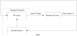
- FIG.2 illustrates a high level architecture enabling a method for modeling a neuronal controller exhibiting human postural sway, in accordance with an embodiment of the present disclosure.
- FIG.3 illustrates an exemplary flow diagram of a computer implemented method 300 for modeling a neuronal controller exhibiting human postural sway, in accordance with an embodiment of the present disclosure.
- the system 100 includes one or more data storage devices or memory 102 operatively coupled to the one or more processors 104 and is configured to store instructions configured for execution of steps of the method 300 by the one or more processors 104.
- the steps of the method 300 will now be explained in detail with reference to the components of the system 100 of FIG.1 and the architecture of FIG.2 .
- the one or more processors 104 are configured to model, at step 302, the neuronal controller in the form of a Reinforcement Learning (RL) agent based on an inverted pendulum with 1 Degree of Freedom (1DOF) representing a first mechanical model of a human body in the form of a dynamical system.
- the RL agent is trained using a Q-learning technique to learn an optimal state-action value (Q-value) function for a tuneable Markov Decision Process (MDP) model, wherein the modeled neuronal controller is configured to reproduce Center Of Pressure (COP) characteristics in the human body either along the sagittal plane or along the frontal plane separately.
- Q-value state-action value
- MDP tuneable Markov Decision Process
- COP Center Of Pressure
- Markov decision process contains the elements [ S,A, P ( ⁇
- the model based algorithm has no stochasticity associated with state transition.
- a reward policy or a reward function (used interchangeably in the context of the present disclosure) is also modeled deterministically.
- the set of states S , the set of actions A and the reward policy are modeled as described hereinafter.
- X A ⁇ all integers
- the system state comprises of two state variables ⁇ and ⁇ .
- the scope of the state variable ⁇ spans from - ⁇ max to ⁇ max and is represented as ⁇ span . Since the present disclosure deals with discrete MDP, the ⁇ and ⁇ space is discretized by defining boundaries. Boundaries of 'sub-states' in ⁇ space are sampled from a curve represented by equation (2) below.
- n ⁇ represents number of sub-states in the ⁇ space inside ⁇ span and wherein n ⁇ is chosen to be an odd integer.
- a set X ⁇ all integers
- the set containing these boundaries may be represented as given below.
- ⁇ SB ⁇ all y from equation (2)
- scope of the state variable ⁇ spans from - ⁇ to ⁇ .
- Sub-state -1 spans from - ⁇ to - ⁇ max and state - n ⁇ spans from ⁇ max to ⁇ , where n ⁇ represents number of sub-states in the ⁇ domain.
- n ⁇ represents number of sub-states in the ⁇ space inside ⁇ span .
- ⁇ SB ⁇ all y from equation (3)
- the i th element of the set spans the ⁇ space as shown below.
- the elements of the set S is a combination of elements of the sets S ⁇ and S ⁇ respectively.
- the reward policy or the reward function may be modeled in multiple approaches as discussed hereinafter.
- the significance of this reward policy is that it encodes the objective of making the inverted pendulum reach the vertical state and stay in the same state.
- Reward policy-4 A negative reward policy is also adapted frequently where the RL agent gets a negative reward of -10 or a punishment of 10 when the inverted pendulum falls out of ⁇ max and ⁇ max .
- s , a )) and discount factor ( ⁇ ) Considering the system dynamics are known, the need for finding the transitional probability is averted.
- the parameters of the MDP model may include:
- the Q-learning technique which is an off-policy algorithm for temporal difference learning, is configured to learn to generate a torque representing an action for each state of the inverted pendulum by receiving proprioceptive inputs in the form of angle and angular velocity of the pivot joint of the inverted pendulum; and generating the torque at the pivot joint of the inverted pendulum based on the received proprioceptive inputs to maintain an upright posture of the inverted pendulum.
- the optimal state-action value (Q-value) function is in the form of a look-up table.
- the algorithm for Q-learning technique may be represented as given below:
- the Center Of Pressure (COP) characteristics in the human body either along the sagittal or along the frontal plane are reproduced separately in accordance with a dynamical equation based on overall mass of the human body being concentrated at the point of Center Of Mass (COM) located at the 2 nd lumbar vertebrae of the human body, an approximate height of the 2 nd lumbar vertebrae, moment of inertia of the inverted pendulum, angle of the inverted pendulum with respect to the direction of gravity, gravitational acceleration, a stiffness constant and a damping constant, wherein the stiffness constant and the damping constant denote pivot joint properties of the inverted pendulum.
- COM Point of Center Of Mass
- FIG.4 illustrates a 1 Degree Of Freedom (1DOF) inverted pendulum representing a free body diagram of a simplified human body in the sagittal plane, in accordance with an embodiment of the present disclosure.
- the one or more processors 104 are configured to derive, at step 304, dynamical equations of a Spherical Inverted Pendulum (SIP) with respect to the global coordinate system.
- SIP Spherical Inverted Pendulum
- the SIP represents a second mechanical model of the human body that is capable of exhibiting postural sway along both the frontal plane and the sagittal plane together.
- the dynamical equations are derived by using Lagrange's equations with two independent state variables ( ⁇ x and ⁇ y ) that represent angular deviation of the SIP about a pivot joint and along x and y axes respectively of the global coordinate system, wherein the pivot joint characterizes an ankle joint of the human body.
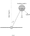
- FIG.5 illustrates an SIP having 2 DOF with the two state variables, ⁇ x and ⁇ y, in accordance with an embodiment of the present disclosure.
- the reference plan passes through the origin, there are two sets of equations for the SIP, a set representing above and below the reference planes respectively.
- ( l x , l y , l z ) is a Cartesian co-ordinate system representation of the position of the pendulum mass.
- m and l represent pendulum mass and length of the shaft of the SIP respectively.
- kinetic energy, potential energy and Lagrangian may be derived as below.
- l x l tan ⁇ y 1 + tan 2 ⁇ x + tan 2 ⁇ y
- l y l tan ⁇ x 1 + tan 2 ⁇ x + tan 2 ⁇ y
- l z ⁇ l 1 + tan 2 ⁇ x + tan 2 ⁇ y
- Plugging equation (13) in equation (9) gives the velocity components along the x, y, and z axes as follows:
- the one or more processors 104 are configured to model, at step 306, the human postural sway both along the sagittal plane and along the frontal plane together using the modeled neuronal controller and the derived dynamical equations of the SIP by tuning (i) a reward function comprised in the modeled neuronal controller and (ii) a set of parameters to balance the SIP such that the postural sway characteristics generated by the modeled neuronal controller match the postural sway characteristics of one or more control subjects.
- the set of parameters include parameters of the MDP model and the three additional parameters associated with physiology of the human body.
- the parameters associated with physiology of the human body may include White Gaussian Noise (WGN) added to the generated torque to represent a real world noisy biological system; filtering factor ( ⁇ ) added to portray signaling characteristics of a neuromuscular junction; and Scaling Factor ( SF ) introduced to scale down the magnitude of the generated torque for each state of the inverted pendulum after the training of the RL agent is completed, wherein completion of the training is represented by a balanced SIP.
- WGN White Gaussian Noise
- ⁇ filtering factor
- SF Scaling Factor
- the model sway characteristics were modeled without incorporating the filtering factor, the scaling factor and the noise.
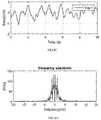
- the closest human postural sway characteristics generated by the model of the present disclosure are illustrated in FIG.6A through FIG.6D and FIG.7A through FIG.7D .
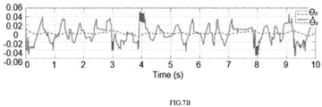
- FIG.7A and FIG.7B illustrate variance of the angle of the SIP and the angular velocity of the SIP with respect to the x axis and the y axis respectively ( ⁇ x , ⁇ y , ⁇ x , ⁇ y ) w.r.t time.
- FIG.7C illustrates a plot of applied torques ⁇ x , ⁇ y at the pivot joint by the neuronal controller of the present disclosure. It may be noted that the maximum torque is approximately 166.67 Nm.
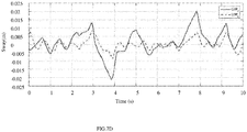
- FIG.7D illustrates COP movement along the x axis and the y axis with parameter values stated with reference to FIG.6A through FIG.6D .
- the additional parameters viz., the filtering factor ( ⁇ ⁇ y , ⁇ ⁇ x ), the noise amplitude ( c ⁇ x , c ⁇ y ) and the scaling factor( SF ⁇ y , SF ⁇ x ) were then introduced which resulted in the human postural sway characteristics as seen in the experimental data.
- the model of the present disclosure produced an expected sway as depicted in FIG.8A through FIG.8D and FIG.9A through FIG.9D .
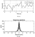
- FIG.8A and 8B illustrate the COP characteristics along the x axis and a corresponding frequency spectrum while FIG.8C and FIG.8D illustrate the COP characteristics along the y axis and a corresponding frequency spectrum.
- the frequency spectrum is spread between 0 to 1 Hz as observed in the experimental data.
- FIG.9A and FIG.9B illustrate variance of the angle of the SIP and the angular velocity of the SIP with respect to the x axis and the y axis respectively ( ⁇ x , ⁇ y , ⁇ x , ⁇ y ) w.r.t time.
- FIG.9C illustrates a plot of applied torques ⁇ x , ⁇ y at the pivot joint by the neuronal controller of the present disclosure.
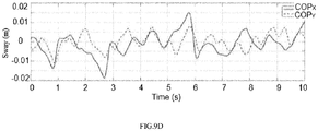
- FIG.9D illustrates COP movement along the x axis and the y axis with parameter values used with reference to FIG.8A through FIG.8D .
- a frequency spectrum representative of the postural sway of the test subject may be derived. Accordingly, using the neuronal controller model described above a best set of parameters that correspond to the postural sway of the test subject can be derived. Deviation of the derived set of parameters from those of the one or more control subjects provides insights into balance impairments, if any, associated with the test subject.
- the mathematical concepts disclosed in the description of the method of the present disclosure are integrated into a practical application of modeling a neuronal controller that exhibits human postural sway so that an analyses of the postural balance of the test subject can be performed and subject specific rehabilitation protocols may be prescribed.
- the hardware device can be any kind of device which can be programmed including e.g. any kind of computer like a server or a personal computer, or the like, or any combination thereof.
- the device may also include means which could be e.g. hardware means like e.g. an application-specific integrated circuit (ASIC), a field-programmable gate array (FPGA), or a combination of hardware and software means, e.g.
- ASIC application-specific integrated circuit
- FPGA field-programmable gate array
- the means can include both hardware means and software means.
- the method embodiments described herein could be implemented in hardware and software.
- the device may also include software means.
- the embodiments may be implemented on different hardware devices, e.g. using a plurality of CPUs.
- the embodiments herein can comprise hardware and software elements.
- the embodiments that are implemented in software include but are not limited to, firmware, resident software, microcode, etc.
- the functions performed by various modules described herein may be implemented in other modules or combinations of other modules.
- a computer-usable or computer readable medium can be any apparatus that can comprise, store, communicate, propagate, or transport the program for use by or in connection with the instruction execution system, apparatus, or device.
- a computer-readable storage medium refers to any type of physical memory on which information or data readable by a processor may be stored.
- a computer-readable storage medium may store instructions for execution by one or more processors, including instructions for causing the processor(s) to perform steps or stages consistent with the embodiments described herein.
- the term "computer-readable medium” should be understood to include tangible items and exclude carrier waves and transient signals, i.e., be non-transitory. Examples include random access memory (RAM), read-only memory (ROM), volatile memory, nonvolatile memory, hard drives, CD ROMs, DVDs, flash drives, disks, and any other known physical storage media.
Landscapes
- Health & Medical Sciences (AREA)
- Life Sciences & Earth Sciences (AREA)
- Engineering & Computer Science (AREA)
- Medical Informatics (AREA)
- Public Health (AREA)
- Physics & Mathematics (AREA)
- Biomedical Technology (AREA)
- General Health & Medical Sciences (AREA)
- Pathology (AREA)
- Animal Behavior & Ethology (AREA)
- Molecular Biology (AREA)
- Surgery (AREA)
- Physiology (AREA)
- Heart & Thoracic Surgery (AREA)
- Biophysics (AREA)
- Veterinary Medicine (AREA)
- Artificial Intelligence (AREA)
- Signal Processing (AREA)
- Computer Vision & Pattern Recognition (AREA)
- Psychiatry (AREA)
- Oral & Maxillofacial Surgery (AREA)
- Dentistry (AREA)
- Data Mining & Analysis (AREA)
- Neurology (AREA)
- Primary Health Care (AREA)
- Epidemiology (AREA)
- Neurosurgery (AREA)
- Evolutionary Computation (AREA)
- Theoretical Computer Science (AREA)
- Software Systems (AREA)
- Mathematical Physics (AREA)
- Geometry (AREA)
- Databases & Information Systems (AREA)
- Business, Economics & Management (AREA)
- General Business, Economics & Management (AREA)
- Computing Systems (AREA)
- General Engineering & Computer Science (AREA)
- General Physics & Mathematics (AREA)
- Fuzzy Systems (AREA)
- Power Engineering (AREA)
Abstract
Description
- The present application claims priority from:
Indian Patent Application No. 201921012442, filed on 29th March, 2019 - The disclosure herein generally relates to postural sway analyses, and, more particularly, to systems and computer implemented methods for modeling a neuronal controller exhibiting human postural sway.
- Analyzing human postural sway is critical to detect markers for progression of balance impairments. Typically, balance impairments are caused by altered functions of the central nervous system or sensory or motor functions which may be due to age or pathology. Parkinson's disease and peripheral neuropathy may be deciphered by analyzing the postural sway. Conventionally, a neuronal controller located inside the central nervous system governing the maintenance of the upright posture of the human body is designed from a control system perspective using one or more proportional-integral-derivative (PID) controllers, wherein human postural sway is modeled either along a sagittal plan or along a frontal plane separately resulting in limited insights on intricacies of a governing neuronal controller. Some attempts have also been made to model the neuronal controller using a reinforcement learning (RL) paradigm based on complex actor-critic on-policy algorithms.
- Embodiments of the present disclosure present technological improvements as solutions to one or more of the above-mentioned technical problems recognized by the inventors in conventional systems.
- In an aspect, there is provided a processor implemented method for modeling a neuronal controller exhibiting human postural sway comprising the steps of: modeling, by one or more hardware processors, the neuronal controller in the form of a Reinforcement Learning (RL) agent based on an inverted pendulum with 1 Degree Of Freedom (1DOF) representing a first mechanical model of a human body in the form of a dynamical system, wherein the RL agent is trained using a Q-learning technique to learn an optimal state-action value (Q-value) function for a tuneable Markov Decision Process (MDP) model, wherein the modeled neuronal controller is configured to reproduce Center Of Pressure (COP) characteristics in the human body either along a sagittal plane or along a frontal plane separately; deriving, by the one or more hardware processors, dynamical equations of a Spherical Inverted Pendulum (SIP) with respect to a global coordinate system, wherein the SIP represents a second mechanical model of the human body that exhibits postural sway along both the frontal plane and the sagittal plane together, wherein the dynamical equations are derived by using Lagrange's equations with two independent state variables (θx and θy) being angular deviation of the SIP about a pivot joint and along x and y axes respectively of the global coordinate system, wherein the pivot joint characterizes an ankle joint of the human body; and modeling, by the one or more hardware processors, the human postural sway both along the sagittal plane and along the frontal plane together using the modeled neuronal controller and the derived dynamical equations of the SIP by tuning (i) a reward function comprised in the modeled neuronal controller and (ii) a set of parameters to balance the SIP such that the postural sway characteristics generated by the modeled neuronal controller match the postural sway characteristics of one or more control subjects, wherein the set of parameters include parameters of the MDP model and parameters associated with physiology of the human body.
- In another aspect, there is provided a system for modeling a neuronal controller exhibiting human postural sway, the system comprising: one or more data storage devices operatively coupled to one or more hardware processors and configured to store instructions configured for execution by the one or more hardware processors to: model the neuronal controller in the form of a Reinforcement Learning (RL) agent based on an inverted pendulum with 1 Degree Of Freedom (1DOF) representing a first mechanical model of a human body in the form of a dynamical system, wherein the RL agent is trained using a Q-learning technique to learn an optimal state-action value (Q-value) function for a tuneable Markov Decision Process (MDP) model, wherein the modeled neuronal controller is configured to reproduce Center Of Pressure (COP) characteristics in the human body either along a sagittal plane or along a frontal plane separately; derive dynamical equations of a Spherical Inverted Pendulum (SIP) with respect to a global coordinate system, wherein the SIP represents a second mechanical model of the human body that exhibits postural sway along both the frontal plane and the sagittal plane together, wherein the dynamical equations are derived by using Lagrange's equations with two independent state variables (θx and θy) being angular deviation of the SIP about a pivot joint and along x and y axes respectively of the global coordinate system, wherein the pivot joint characterizes an ankle joint of the human body; and model the human postural sway both along the sagittal plane and along the frontal plane together using the modeled neuronal controller and the derived dynamical equations of the SIP by tuning (i) a reward function comprised in the modeled neuronal controller and (ii) a set of parameters to balance the SIP such that the postural sway characteristics generated by the modeled neuronal controller match the postural sway characteristics of one or more control subjects, wherein the set of parameters include parameters of the MDP model and parameters associated with physiology of the human body.
- In yet another aspect, there is provided a computer program product comprising a non-transitory computer readable medium having a computer readable program embodied therein, wherein the computer readable program, when executed on a computing device, causes the computing device to: model the neuronal controller in the form of a Reinforcement Learning (RL) agent based on an inverted pendulum with 1 Degree Of Freedom (1DOF) representing a first mechanical model of a human body in the form of a dynamical system, wherein the RL agent is trained using a Q-learning technique to learn an optimal state-action value (Q-value) function for a tuneable Markov Decision Process (MDP) model, wherein the modeled neuronal controller is configured to reproduce Center Of Pressure (COP) characteristics in the human body either along a sagittal plane or along a frontal plane separately; derive dynamical equations of a Spherical Inverted Pendulum (SIP) with respect to a global coordinate system, wherein the SIP represents a second mechanical model of the human body that exhibits postural sway along both the frontal plane and the sagittal plane together, wherein the dynamical equations are derived by using Lagrange's equations with two independent state variables (θx and θy) being angular deviation of the SIP about a pivot joint and along x and y axes respectively of the global coordinate system, wherein the pivot joint characterizes an ankle joint of the human body; and model the human postural sway both along the sagittal plane and along the frontal plane together using the modeled neuronal controller and the derived dynamical equations of the SIP by tuning (i) a reward function comprised in the modeled neuronal controller and (ii) a set of parameters to balance the SIP such that the postural sway characteristics generated by the modeled neuronal controller match the postural sway characteristics of one or more control subjects, wherein the set of parameters include parameters of the MDP model and parameters associated with physiology of the human body.
- In accordance with an embodiment of the present disclosure, the Q-learning technique is configured to learn to generate a torque representing an action for each state of the inverted pendulum by: receiving proprioceptive inputs in the form of angle and angular velocity of the pivot joint of the inverted pendulum; and generating the torque at the pivot joint of the inverted pendulum based on the received proprioceptive inputs to maintain an upright posture of the inverted pendulum.
- In accordance with an embodiment of the present disclosure, the one or more hardware processors are configured to perform the step of modeling a neuronal controller by reproducing the Center Of Pressure (COP) characteristics in the human body either along the sagittal or along the frontal plane separately in accordance with a dynamic equation based on overall mass m of the human body being concentrated at the point of Center Of Mass (COM) located at the 2nd lumbar vertebrae of the human body, an approximate height L of the 2nd lumbar vertebrae, moment of inertia of the inverted pendulum I, angle of the inverted pendulum θ with respect to the direction of gravity, gravitational acceleration g, a stiffness constant K and a damping constant B, wherein the stiffness constant and the damping constant denote pivot joint properties of the inverted pendulum.
- In accordance with an embodiment of the present disclosure, the parameters of the MDP model include: nθ representing resolution of states in θ domain (from θmax to -θmax ); nθ̇ representing resolution of states in θ̇ domain (from θ̇max to -θ̇max ); nA representing resolution of states in τ domain (from τmax to - τmax ); τmax representing the maximum torque exertable on the pivot joint or the boundary of the τ domain; θmax representing the boundary of the θ domain; θ̇max representing a finite boundary of the θ̇ domain; pa representing property of a curve from which torque values in the τ domain is sampled; pθ representing property of a curve from which boundaries of states of the θ domain is sampled; and pθ̇ representing property of a curve from which boundaries of the states of the θ̇ domain is sampled; and the parameters associated with physiology of the human body include: White Gaussian Noise (WGN) added to the generated torque to represent a real world noisy biological system; filtering factor (λ) added to portray signaling characteristics of a neuromuscular junction; and Scaling Factor (SF) introduced to scale down the magnitude of the generated torque for each state of the inverted pendulum after the training of the RL agent is completed, wherein completion is of the training is represented by a balanced SIP.
- It is to be understood that both the foregoing general description and the following detailed description are exemplary and explanatory only and are not restrictive of the invention, as claimed.
- The accompanying drawings, which are incorporated in and constitute a part of this disclosure, illustrate exemplary embodiments and, together with the description, serve to explain the disclosed principles.
-
FIG.1 illustrates an exemplary block diagram of a system for modeling a neuronal controller exhibiting human postural sway, in accordance with an embodiment of the present disclosure. -
FIG.2 illustrates a high level architecture enabling a method for modeling a neuronal controller exhibiting human postural sway, in accordance with an embodiment of the present disclosure. -
FIG.3 illustrates an exemplary flow diagram of a computer implemented method for modeling a neuronal controller exhibiting human postural sway, in accordance with an embodiment of the present disclosure. -
FIG.4 illustrates a 1 Degree Of Freedom (1DOF) inverted pendulum representing a free body diagram of a simplified human body in the sagittal plane, in accordance with an embodiment of the present disclosure. -
FIG.5 illustrates a Spherical Inverted Pendulum (SIP) having 2 DOF with two state variables, θx and θy, in accordance with an embodiment of the present disclosure. -
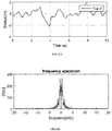
FIG.6A and FIG.6B illustrate Center Of Pressure (COP) characteristics along x axis and a corresponding frequency spectrum respectively; andFIG.6C and FIG.6D illustrate the COP characteristics along y axis and a corresponding frequency spectrum respectively, for a set of parameters, without introducing parameters associated with physiology of the human body, in accordance with an embodiment of the present disclosure. -
FIG.7A andFIG.7B illustrate variance of the angle of the SIP and the angular velocity of the SIP with respect to the x axis and the y axis respectively (θx, θy, θ̇x, θ̇y ) w.r.t time;FIG.7C illustrates a plot of applied torques τx, τy at a pivot joint by the neuronal controller andFIG.7D illustrates COP movement along the x axis and the y axis for the set of parameters referred inFIG.6A through FIG.6D . -
FIG.8A and FIG.8B illustrate the COP characteristics along the x axis and a corresponding frequency spectrum respectively; andFIG.8C and FIG.8D illustrate the COP characteristics along the y axis and a corresponding frequency spectrum respectively, after introducing parameters associated with physiology of the human body, in accordance with an embodiment of the present disclosure. -
FIG.9A andFIG.9B illustrate the variance of the angle of the SIP and the angular velocity of the SIP with respect to the x axis and the y axis respectively (θx, θy, θ̇x, θ̇y ) w.r.t time;FIG.9C illustrates a plot of applied torques τx, τy at a pivot joint by the neuronal controller andFIG.9D illustrates COP movement along the x axis and the y axis for the parameters used with reference toFIG.8A through FIG.8D . - Exemplary embodiments are described with reference to the accompanying drawings. In the figures, the left-most digit(s) of a reference number identifies the figure in which the reference number first appears. Wherever convenient, the same reference numbers are used throughout the drawings to refer to the same or like parts. While examples and features of disclosed principles are described herein, modifications, adaptations, and other implementations are possible without departing from the spirit and scope of the disclosed embodiments. It is intended that the following detailed description be considered as exemplary only, with the true scope and spirit being indicated by the following claims.
- State of the art techniques for analyzing human postural sway, model the human postural sway either along a sagittal plane or along a frontal plane separately. Modeling separately along the anatomical planes only give lower dimensional projection of higher dimensional dynamics which in turn compromises the overall picture portraying the human postural sway. Also, the attempts were directed to designing the neuronal controller located inside the central nervous system governing the maintenance of the upright posture of the human body from a control system perspective using PID controllers. Using PID controller only gives rise to limited set of parameters with very less neurophysiological significance. Some attempts to model the neuronal controller using Reinforcement Learning (RL) paradigm were actor-critic on-policy algorithms that address optimization of two redundant parallel entities viz., the 'policy' and the 'actor' which was relatively complex and computationally inefficient.
- The methods and systems of the present disclosure firstly facilitate designing the neuronal controller using a simplified RL algorithm capable of producing diverse sway characteristics either in the sagittal plane or in the front plane separately using a simple inverted pendulum representing a mechanical model of a human body. Dynamical equations of a Spherical Inverted Pendulum (SIP) are derived with respect to a global coordinate system. The modeled neuronal controller is then adapted to exhibit diverse sway characteristics in the sagittal plane and in the front plane together. The present disclosure also provides parameters which enable the sway characteristics exhibited by the modeled neuronal controller to be close to normal and pathological conditions seen in the real world. Systems and methods of the present disclosure find application in analyzing the postural balance of a subject so that subject specific rehabilitation protocols may be recommended.
- Referring now to the drawings, and more particularly to
FIG.1 through FIG.9D , where similar reference characters denote corresponding features consistently throughout the figures, there are shown preferred embodiments and these embodiments are described in the context of the following exemplary system and/or method. -
FIG.1 illustrates an exemplary block diagram of asystem 100 for modeling a neuronal controller exhibiting human postural sway, in accordance with an embodiment of the present disclosure. In an embodiment, thesystem 100 includes one ormore hardware processors 104, communication interface device(s) or input/output (I/O) interface(s) 106, and one or more data storage devices ormemory 102 operatively coupled to the one ormore processors 104. The one ormore processors 104 can be implemented as one or more microprocessors, microcomputers, microcontrollers, digital signal processors, central processing units, state machines, graphics controllers, logic circuitries, and/or any devices that manipulate signals based on operational instructions. Among other capabilities, the processor(s) are configured to fetch and execute computer-readable instructions stored in the memory. In the context of the present disclosure, the expressions 'processors' and 'hardware processors' may be used interchangeably. In an embodiment, thesystem 100 can be implemented in a variety of computing systems, such as laptop computers, notebooks, hand-held devices, workstations, mainframe computers, servers, a network cloud and the like. - The I/O interface(s) 106 can include a variety of software and hardware interfaces, for example, a web interface, a graphical user interface, and the like and can facilitate multiple communications within a wide variety of networks N/W and protocol types, including wired networks, for example, LAN, cable, etc., and wireless networks, such as WLAN, cellular, or satellite. In an embodiment, the I/O interface(s) can include one or more ports for connecting a number of devices to one another or to another server.
- The
memory 102 may include any computer-readable medium known in the art including, for example, volatile memory, such as static random access memory (SRAM) and dynamic random access memory (DRAM), and/or non-volatile memory, such as read only memory (ROM), erasable programmable ROM, flash memories, hard disks, optical disks, and magnetic tapes. In an embodiment, one or more modules (not shown) of thesystem 100 can be stored in thememory 102. -
FIG.2 illustrates a high level architecture enabling a method for modeling a neuronal controller exhibiting human postural sway, in accordance with an embodiment of the present disclosure.FIG.3 illustrates an exemplary flow diagram of a computer implementedmethod 300 for modeling a neuronal controller exhibiting human postural sway, in accordance with an embodiment of the present disclosure. In an embodiment, thesystem 100 includes one or more data storage devices ormemory 102 operatively coupled to the one ormore processors 104 and is configured to store instructions configured for execution of steps of themethod 300 by the one ormore processors 104. The steps of themethod 300 will now be explained in detail with reference to the components of thesystem 100 ofFIG.1 and the architecture ofFIG.2 . Although process steps, method steps, techniques or the like may be described in a sequential order, such processes, methods and techniques may be configured to work in alternate orders. In other words, any sequence or order of steps that may be described does not necessarily indicate a requirement that the steps be performed in that order. The steps of processes described herein may be performed in any order practical. Further, some steps may be performed simultaneously. - In accordance with an embodiment of the present disclosure, the one or
more processors 104 are configured to model, atstep 302, the neuronal controller in the form of a Reinforcement Learning (RL) agent based on an inverted pendulum with 1 Degree of Freedom (1DOF) representing a first mechanical model of a human body in the form of a dynamical system. In an embodiment, the RL agent is trained using a Q-learning technique to learn an optimal state-action value (Q-value) function for a tuneable Markov Decision Process (MDP) model, wherein the modeled neuronal controller is configured to reproduce Center Of Pressure (COP) characteristics in the human body either along the sagittal plane or along the frontal plane separately. - The modeling of the MDP for the RL agent, in accordance with an embodiment of the present disclosure is performed as described herein after. Markov decision process contains the elements [S,A, P(ś|s,a), E[r|s, á,s]γ], wherein S represents a set of states, A represents a set of actions, P(ś|s, a) represents a transition probability, γ represents a discount factor and E[r|s, á, s] represents an expected reward for a current state s, immediate action a and next state ś. The model based algorithm has no stochasticity associated with state transition. Accordingly, given a particular state s (in terms of θ and θ̇) and action a (in terms of torque at a pivot joint), system dynamics reveal an immediate next state. A reward policy or a reward function (used interchangeably in the context of the present disclosure) is also modeled deterministically. The set of states S, the set of actions A and the reward policy are modeled as described hereinafter.
- Modeling the set of actions A: The actions are sampled using a curve represented as:

equation 1. and τmax represents a maximum torque applied to the pivot joint. Let set, XA = {all integers | - (nA - 1)/2 ≤ n ≤ (nA - 1)/2}, where xa ∈ XA and n denotes an integer number. To obtain, nA number of actions, the curve represented by equation (1) is sampled for all integer values in the range -(nA - 1)/2 ≤ n ≤ (nA - 1)/2 for all elements of the set XA or A = {all y from equation (1)|x ∈ XA }. - Modeling the set of States (S): The system state comprises of two state variables θ and θ̇. The scope of the state variable θ spans from -θmax to θmax and is represented as θspan. Since the present disclosure deals with discrete MDP, the θ and θ̇ space is discretized by defining boundaries. Boundaries of 'sub-states' in θ space are sampled from a curve represented by equation (2) below.


θSB = {all y from equation (2)| x ∈ Xθ }
or, θSBi ∈ θSB where, i ∈ Xθ - On similar lines, scope of the state variable θ̇ spans from -∞ to ∞. Sub-state -1 spans from -∞ to -θ̇ max and state -nθ̇ spans from θ̇ max to ∞, where nθ̇ represents number of sub-states in the θ̇ domain. From -θ̇max to θ̇max, there are nθ̇ - 2 states, boundaries of which are defined by taking nθ̇ -1 samples of all elements of a set


- Also, the set containing these boundaries may be represented as given below.
θ̇ SB = {all y from equation (3)| x ∈ X θ̇}
or, θ̇SBi ∈ θ̇SB where, i ∈ Xθ̇ - If Sθ is a set of sub-states corresponding to the state variable θ, then,

- θ SB
i-1 ≤ θ < θSBi for i < 0; - θ SB
i-1 ≤ θ < θ SBi+1 for i = 0; - θSB
i ≤ θ < θ SBi+1 for i > 0; - And the ith element of the set spans the θ̇ space as shown below. θ̇ < θ̇SB
i for
θ̇ > θ̇SBi for
θ̇ SBi-1 ≤ θ̇ < θ̇SBi for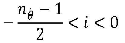
θ̇ SBi-1 ≤ θ̇ < θ̇ SBi+1 for i = 0
θ̇SBi ≤ θ̇ < θ̇ SBi+1 for
The elements of the set S is a combination of elements of the sets Sθ and Sθ̇ respectively. - Modeling the Reward (E[r|ś,a,s]): In accordance with the present disclosure, the reward policy or the reward function may be modeled in multiple approaches as discussed hereinafter.
- Reward policy-1: The RL agent gets a reward of +1 when ś (state of the system at t+1) falls inside S θ
0 (which spans between two nearest θ boundaries on either side of θ = 0 as specified in θSB ) i.e. the reward states comes under the set:
- Reward policy-2: The RL agent gets a reward of +1 when ś falls inside the sub-state S θ
0 and S θ̇0 simultaneously, in which case the reward state is only one state out of all the elements of the set S. So, SR = {(S θ0 ,Sθ̇0 )}. The significance of this reward policy is that it encodes the objective of making the inverted pendulum reach the vertical state and stay in the same state. - Reward policy-3: A Gaussian reward policy over the state space is represented as follows:

- Reward policy-4: A negative reward policy is also adapted frequently where the RL agent gets a negative reward of -10 or a punishment of 10 when the inverted pendulum falls out of θmax and θ̇max .
- Transitional probability (P(ś|s,a)) and discount factor (γ): Considering the system dynamics are known, the need for finding the transitional probability is averted. The discount factor (γ) which is a parameter of temporal difference learning, is chosen to be 0.1.
- In accordance with an embodiment, the parameters of the MDP model may include:
- nθ representing resolution of states in θ domain (from θmax to -θmax);
- nθ̇ representing resolution of states in θ̇ domain (from θ̇max to -θ̇max );
- nA representing resolution of states in τ domain (from τmax to -τmax );
- τmax representing the maximum torque exertable on the pivot joint or the boundary of the τ domain;
- θ max representing the boundary of the θ domain;
- θ̇ max representing a finite boundary of the θ̇ domain;
- pa representing property of a curve from which torque values in the τ domain is sampled;
- pθ representing property of a curve from which boundaries of states of the θ domain is sampled; and
- pθ̇ representing property of a curve from which boundaries of the states of the θ̇ domain is sampled.
- In an embodiment, the Q-learning technique, which is an off-policy algorithm for temporal difference learning, is configured to learn to generate a torque representing an action for each state of the inverted pendulum by receiving proprioceptive inputs in the form of angle and angular velocity of the pivot joint of the inverted pendulum; and generating the torque at the pivot joint of the inverted pendulum based on the received proprioceptive inputs to maintain an upright posture of the inverted pendulum. In an embodiment of the present disclosure, the optimal state-action value (Q-value) function is in the form of a look-up table.
- In accordance with the present disclosure, the algorithm for Q-learning technique may be represented as given below:
- Initialize Q(s, a) arbitrarily
- Repeat (for each episode):
- Initialize s
- Repeat (for each step of the episode):
- Choose a from s using a policy derived from Q
(e.g., ε-greedy) - Take action a, observe r,ś

- Choose a from s using a policy derived from Q
- Until s is terminal,
- where α represents a learning rate, value of which typically lies between 0 and 1. α = 0 means Q(s, a) is not updated or there is no learning, whereas α = 1 means Q(s, a) is updated depending on an expected total reward achieved in a recent episode and is independent of a previous Q(s, a) value for a particular state and action.. Also, ε represents an exploration factor associated with the ε-greedy policy that aims to define balance between exploration and exploitation of immediate reinforcement learning. A value of ε near 0 ensures the RL agent prefers exploitation over exploration and vice versa.
- The s and a are the current state and immediate action taken at time t and ś and á are the state and the action taken at time t+1 respectively. It is proven that once the Q values are learnt for a significant number of episodes under the ε-greedy policy, the Q- learning algorithm converges to close approximation of optimal state-action value function (Q ∗(s, a)) with
probability 1. Once the RL agent has learnt the Q values for significant number of episodes, the RL agent is ready for exploitation only (means ε = 0), i.e. at a given state it will choose the action with maximum Q value by
- In accordance with an embodiment of the present disclosure, the Center Of Pressure (COP) characteristics in the human body either along the sagittal or along the frontal plane are reproduced separately in accordance with a dynamical equation based on overall mass of the human body being concentrated at the point of Center Of Mass (COM) located at the 2nd lumbar vertebrae of the human body, an approximate height of the 2nd lumbar vertebrae, moment of inertia of the inverted pendulum, angle of the inverted pendulum with respect to the direction of gravity, gravitational acceleration, a stiffness constant and a damping constant, wherein the stiffness constant and the damping constant denote pivot joint properties of the inverted pendulum.
FIG.4 illustrates a 1 Degree Of Freedom (1DOF) inverted pendulum representing a free body diagram of a simplified human body in the sagittal plane, in accordance with an embodiment of the present disclosure. In an embodiment, the dynamical equation may be represented as:
- where m represents the overall mass of the human body being concentrated at the point of Center Of Mass (COM) located at the 2nd lumbar vertebrae of the human body;
- L represents the approximate height of the 2nd lumbar vertebrae;
- θ represents angle of the inverted pendulum;
- g represents gravitational acceleration;
- I represents moment of inertia of the inverted pendulum;
- K represents the stiffness constant; and
- B represents the damping constant.
- In accordance with an embodiment of the present disclosure, the one or
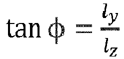
more processors 104 are configured to derive, atstep 304, dynamical equations of a Spherical Inverted Pendulum (SIP) with respect to the global coordinate system. In accordance with the present disclosure, the SIP represents a second mechanical model of the human body that is capable of exhibiting postural sway along both the frontal plane and the sagittal plane together. In an embodiment, the dynamical equations are derived by using Lagrange's equations with two independent state variables (θx and θy) that represent angular deviation of the SIP about a pivot joint and along x and y axes respectively of the global coordinate system, wherein the pivot joint characterizes an ankle joint of the human body.FIG.5 illustrates an SIP having 2 DOF with the two state variables, θx and θy, in accordance with an embodiment of the present disclosure. As the reference plan passes through the origin, there are two sets of equations for the SIP, a set representing above and below the reference planes respectively. InFIG.5 , (lx , ly , lz ) is a Cartesian co-ordinate system representation of the position of the pendulum mass. m and l represent pendulum mass and length of the shaft of the SIP respectively. - In accordance with the present disclosure, the dynamical equations are derived as described hereinafter. The Lagrange's equations are as given below.




- Further, in accordance with the present disclosure, kinetic energy, potential energy and Lagrangian may be derived as below.
Using the values of cos θ, sin θ, cos φ and sin φ in equation (10),


- In accordance with an embodiment of the present disclosure, using the kinetic energy and potential energy in equation (6), provides the Lagrangian (L) and plugging the Lagrangian in equation (5), the dynamical equations of the SIP are represented as:
for θ = 0 to 90°, θ being the polar or zenith angle of the spherical coordinate system,


- The dynamical equations of the SIP were simulated for the following initial condition:
(θx = 2.3562 rad, θ̇x = 2.01 rad/sec, θy = -2.3562 rad, θ̇y = 2.01 ṙad/sec), wherein given a θ̇y, the θ̇x is calculated by making vz = 0 in the equation vz =

- In accordance with an embodiment of the present disclosure, the one or
more processors 104 are configured to model, atstep 306, the human postural sway both along the sagittal plane and along the frontal plane together using the modeled neuronal controller and the derived dynamical equations of the SIP by tuning (i) a reward function comprised in the modeled neuronal controller and (ii) a set of parameters to balance the SIP such that the postural sway characteristics generated by the modeled neuronal controller match the postural sway characteristics of one or more control subjects. - To validate model generated sway characteristics of the present disclosure, experimental data pertaining to the human postural sway, in the form of the COP characteristics of four control subjects in the age group 25 to 40 years having height in the range 5'3" to 5'10", and body weight in the
range 50 to 70kg, when standing bipedally for approximately 30 secs were collected. It was noted from the frequency spectrum of the COP-x signal where |X(k)|is Fourier coefficient corresponds to the kth frequency spectrum, that the frequency spectrum is almost uniformly distributed from 0 to 1 Hz except few peaks at very low frequency component, comparable to DC component. The stated experimental data is also referred later in the description with reference to the description forFIG. 6A through FIG.6D ,FIG.7A through FIG.7D ,FIG.8A through FIG.8D andFIG.9A through FIG.9D . To match the human postural sway seen in the control subjects, in accordance with the present disclosure, three additional parameters are introduced in the model. In accordance with the present disclosure, the set of parameters include parameters of the MDP model and the three additional parameters associated with physiology of the human body. - In accordance with an embodiment, the parameters associated with physiology of the human body may include White Gaussian Noise (WGN) added to the generated torque to represent a real world noisy biological system; filtering factor (λ) added to portray signaling characteristics of a neuromuscular junction; and Scaling Factor (SF) introduced to scale down the magnitude of the generated torque for each state of the inverted pendulum after the training of the RL agent is completed, wherein completion of the training is represented by a balanced SIP.
- In accordance with an embodiment of the present disclosure, a relationship between the generated torque by the modeled neuronal controller and the torque applied to the dynamical system based on the parameters associated with physiology of the human body is represented as:


wherein
- τ(t) represents the torque applied to the dynamical system,
- τSF (t) represents the torque after introducing the Scaling Factor,
- τNC represents the generated torque by the modeled neuronal controller,
- WGN represents the White Gaussian Noise of
magnitude 1, and - c represents noise amplitude.
- The model sway characteristics were modeled without incorporating the filtering factor, the scaling factor and the noise. The closest human postural sway characteristics generated by the model of the present disclosure are illustrated in
FIG.6A through FIG.6D andFIG.7A through FIG.7D . Particularly,FIG.6A and FIG.6B illustrate the COP characteristics along the x axis and a corresponding frequency spectrum whileFIG.6C and FIG.6D illustrate the COP characteristics along the y axis and a corresponding frequency spectrum for the following set of parameters: nθx = 15, nθy = 15; nθ̇x = 7, nθ̇y = 7, nτx = 9, nτy = 9 τxmax = 500 Nm , τymax = 500 Nm,
max = θ̇ymax = 0.3 rad/s, pθx = 3, pθy = 3, pθ̇ x = 2, pθ̇y = 2, pτx = 3, pτy = 3, σθx = 0.01 rad, σθy = 0.01 rad, σθ̇x = 0.045, σθ̇y = 0.045, SFτx = 3, SFτy = 3. It may be noted that the frequency spectrum of COP-x is closely matched with the experimental data (detailed above) but the frequency spectrum is twice as spread as the experimental data for COP-y. -
FIG.7A andFIG.7B illustrate variance of the angle of the SIP and the angular velocity of the SIP with respect to the x axis and the y axis respectively (θx, θy, θ̇x, θ̇y ) w.r.t time.FIG.7C illustrates a plot of applied torques τx, τy at the pivot joint by the neuronal controller of the present disclosure. It may be noted that the maximum torque is approximately 166.67 Nm.FIG.7D illustrates COP movement along the x axis and the y axis with parameter values stated with reference toFIG.6A through FIG.6D . - The additional parameters viz., the filtering factor (λτ
y , λτx ), the noise amplitude (cτx , cτy ) and the scaling factor(SFτy , SFτx ) were then introduced which resulted in the human postural sway characteristics as seen in the experimental data. After tuning the parameters of the MDP model, the additional parameters and choosing the Reward policy-3 with appropriate standard deviation, the model of the present disclosure produced an expected sway as depicted inFIG.8A through FIG.8D andFIG.9A through FIG.9D . Particularly,FIG.8A and 8B illustrate the COP characteristics along the x axis and a corresponding frequency spectrum whileFIG.8C and FIG.8D illustrate the COP characteristics along the y axis and a corresponding frequency spectrum. It may be noted that the frequency spectrum is spread between 0 to 1 Hz as observed in the experimental data.FIG.9A andFIG.9B illustrate variance of the angle of the SIP and the angular velocity of the SIP with respect to the x axis and the y axis respectively (θx, θy, θ̇x, θ̇y ) w.r.t time.FIG.9C illustrates a plot of applied torques τx, τy at the pivot joint by the neuronal controller of the present disclosure.FIG.9D illustrates COP movement along the x axis and the y axis with parameter values used with reference toFIG.8A through FIG.8D . The illustrated sway characteristics were observed using the following set of parameters: nθx = 15, nθy = 15; nθ̇x = 7, nθy = 7, nτx = 9, nτy = 9 τxmax = 500 Nm , τymax = 500 Nm,
max = θ̇ymax = 0.3 rad/s, pθx = 3, pθy = 3, pθ̇x = 2, pθ̇y = 2, pτx = 3, pτy = 3, σθx = 0.01 rad, σθy = 0.01 rad, σθ̇x = 0.045, σθ̇y = 0.045, λτx = 0.8, λτy = 0.8, SFτx = 3, SFτy = 3, cτx = 7.75 Nm, cτy = 7.75 Nm. - In accordance with the present disclosure, by obtaining the COP characteristics of a test subject, using say, a pressure sensing board, a frequency spectrum representative of the postural sway of the test subject may be derived. Accordingly, using the neuronal controller model described above a best set of parameters that correspond to the postural sway of the test subject can be derived. Deviation of the derived set of parameters from those of the one or more control subjects provides insights into balance impairments, if any, associated with the test subject. Thus the mathematical concepts disclosed in the description of the method of the present disclosure are integrated into a practical application of modeling a neuronal controller that exhibits human postural sway so that an analyses of the postural balance of the test subject can be performed and subject specific rehabilitation protocols may be prescribed.
- The written description describes the subject matter herein to enable any person skilled in the art to make and use the embodiments. The scope of the subject matter embodiments is defined by the claims and may include other modifications that occur to those skilled in the art. Such other modifications are intended to be within the scope of the claims if they have similar elements that do not differ from the literal language of the claims or if they include equivalent elements with insubstantial differences from the literal language of the claims.
- It is to be understood that the scope of the protection is extended to such a program and in addition to a computer-readable means having a message therein; such computer-readable storage means contain program-code means for implementation of one or more steps of the method, when the program runs on a server or mobile device or any suitable programmable device. The hardware device can be any kind of device which can be programmed including e.g. any kind of computer like a server or a personal computer, or the like, or any combination thereof. The device may also include means which could be e.g. hardware means like e.g. an application-specific integrated circuit (ASIC), a field-programmable gate array (FPGA), or a combination of hardware and software means, e.g. an ASIC and an FPGA, or at least one microprocessor and at least one memory with software modules located therein. Thus, the means can include both hardware means and software means. The method embodiments described herein could be implemented in hardware and software. The device may also include software means. Alternatively, the embodiments may be implemented on different hardware devices, e.g. using a plurality of CPUs.
- The embodiments herein can comprise hardware and software elements. The embodiments that are implemented in software include but are not limited to, firmware, resident software, microcode, etc. The functions performed by various modules described herein may be implemented in other modules or combinations of other modules. For the purposes of this description, a computer-usable or computer readable medium can be any apparatus that can comprise, store, communicate, propagate, or transport the program for use by or in connection with the instruction execution system, apparatus, or device.
- The illustrated steps are set out to explain the exemplary embodiments shown, and it should be anticipated that ongoing technological development will change the manner in which particular functions are performed. These examples are presented herein for purposes of illustration, and not limitation. Further, the boundaries of the functional building blocks have been arbitrarily defined herein for the convenience of the description. Alternative boundaries can be defined so long as the specified functions and relationships thereof are appropriately performed. Alternatives (including equivalents, extensions, variations, deviations, etc., of those described herein) will be apparent to persons skilled in the relevant art(s) based on the teachings contained herein. Such alternatives fall within the scope and spirit of the disclosed embodiments. Also, the words "comprising," "having," "containing," and "including," and other similar forms are intended to be equivalent in meaning and be open ended in that an item or items following any one of these words is not meant to be an exhaustive listing of such item or items, or meant to be limited to only the listed item or items. It must also be noted that as used herein and in the appended claims, the singular forms "a," "an," and "the" include plural references unless the context clearly dictates otherwise.
- Furthermore, one or more computer-readable storage media may be utilized in implementing embodiments consistent with the present disclosure. A computer-readable storage medium refers to any type of physical memory on which information or data readable by a processor may be stored. Thus, a computer-readable storage medium may store instructions for execution by one or more processors, including instructions for causing the processor(s) to perform steps or stages consistent with the embodiments described herein. The term "computer-readable medium" should be understood to include tangible items and exclude carrier waves and transient signals, i.e., be non-transitory. Examples include random access memory (RAM), read-only memory (ROM), volatile memory, nonvolatile memory, hard drives, CD ROMs, DVDs, flash drives, disks, and any other known physical storage media.
- It is intended that the disclosure and examples be considered as exemplary only, with a true scope and spirit of disclosed embodiments being indicated by the following claims.

Claims (15)
- A processor implemented method for modeling a neuronal controller exhibiting human postural sway (300), the method comprising the steps of:modeling, by one or more hardware processors, the neuronal controller in the form of a Reinforcement Learning (RL) agent based on an inverted pendulum with 1 Degree Of Freedom (1DOF) representing a first mechanical model of a human body in the form of a dynamical system, wherein the RL agent is trained using a Q-learning technique to learn an optimal state-action value (Q-value) function for a tuneable Markov Decision Process (MDP) model, wherein the modeled neuronal controller is configured to reproduce Center Of Pressure (COP) characteristics in the human body either along a sagittal plane or along a frontal plane separately (302);deriving, by the one or more hardware processors, dynamical equations of a Spherical Inverted Pendulum (SIP) with respect to a global coordinate system, wherein the SIP represents a second mechanical model of the human body that exhibits postural sway along both the frontal plane and the sagittal plane together, wherein the dynamical equations are derived by using Lagrange's equations with two independent state variables (θx and θy ) being angular deviation of the SIP about a pivot joint and along x and y axes respectively of the global coordinate system, wherein the pivot joint characterizes an ankle joint of the human body (304); andmodeling, by the one or more hardware processors, the human postural sway both along the sagittal plane and along the frontal plane together using the modeled neuronal controller and the derived dynamical equations of the SIP by tuning (i) a reward function comprised in the modeled neuronal controller and (ii) a set of parameters to balance the SIP such that the postural sway characteristics generated by the modeled neuronal controller match the postural sway characteristics of one or more control subjects, wherein the set of parameters include parameters of the MDP model and parameters associated with physiology of the human body (306).
- The processor implemented method of claim 1, wherein the Q-learning technique is configured to learn to generate a torque representing an action for each state of the inverted pendulum by:receiving proprioceptive inputs in the form of angle and angular velocity of the pivot joint of the inverted pendulum; andgenerating the torque at the pivot joint of the inverted pendulum based on the received proprioceptive inputs to maintain an upright posture of the inverted pendulum.
- The processor implemented method of claim 1, wherein the step of modeling a neuronal controller comprises reproducing the Center Of Pressure (COP) characteristics in the human body either along the sagittal or along the frontal plane separately in accordance with a dynamical equation based on overall mass of the human body being concentrated at the point of Center Of Mass (COM) located at the 2nd lumbar vertebrae of the human body, an approximate height of the 2nd lumbar vertebrae, moment of inertia of the inverted pendulum, angle of the inverted pendulum with respect to the direction of gravity, gravitational acceleration, a stiffness constant and a damping constant, wherein the stiffness constant and the damping constant denote pivot joint properties of the inverted pendulum.
- The processor implemented method of claim 3, wherein the step of modeling a neuronal controller comprises reproducing the Center Of Pressure (COP) characteristics in the human body either along the sagittal or along the frontal plane separately in accordance with the dynamical equation represented as:
 m represents overall mass of the human body being concentrated at the point of Center Of Mass (COM) located at the 2nd lumbar vertebrae of the human body;L represents the approximate height of the 2nd lumbar vertebrae;θ represents angle of the inverted pendulum with respect to the direction of gravity;g represents gravitational acceleration;I represents moment of inertia of the inverted pendulum;K represents the stiffness constant; andB represents the damping constant.
 - The processor implemented method of claim 2, wherein the parameters of the MDP model include:nθ representing resolution of states in θ domain (from θmax to -θmax );nθ̇ representing resolution of states in θ̇ domain (from θ̇max to -θ̇max );nA representing resolution of states in τ domain (from τmax to -τmax );τmax representing the maximum torque exertable on the pivot joint or the boundary of the τ domain;θmax representing the boundary of the θ domain;θ̇ max representing a finite boundary of the θ̇ domain;pa representing property of a curve from which torque values in the τ domain is sampled;pθ representing property of a curve from which boundaries of states of the θ domain is sampled; andpθ̇ representing property of a curve from which boundaries of the states of theθ̇ domain is sampled.
- The processor implemented method of claim 2, wherein the parameters associated with physiology of the human body include:White Gaussian Noise (WGN) added to the generated torque to represent a real world noisy biological system;filtering factor (λ) added to portray signaling characteristics of a neuromuscular junction; andScaling Factor (SF) introduced to scale down the magnitude of the generated torque for each state of the inverted pendulum after the training of the RL agent is completed, wherein completion of the training is represented by a balanced SIP.
- The processor implemented method of claim 6, wherein a relationship between the generated torque by the modeled neuronal controller and the torque applied to the dynamical system based on the parameters associated with physiology of the human body is represented as:


wherein τ(t) represents the torque applied to the dynamical system,τSF (t) represents the torque after introducing the Scaling Factor,τNC represents the generated torque by the modeled neuronal controller,WGN represents the White Gaussian Noise of magnitude 1, andc represents noise amplitude.
 - The processor implemented method of claim 7, wherein the dynamical equations of the SIP are represented as:
for θ = 0 to 90°, θ being the polar or zenith angle of the spherical coordinate

for θ > 90°,

- A system (100) for modeling a neuronal controller exhibiting human postural sway, the system comprising: one or more data storage devices (102) operatively coupled to one or more hardware processors (104) and configured to store instructions configured for execution by the one or more hardware processors to:model the neuronal controller in the form of a Reinforcement Learning (RL) agent based on an inverted pendulum with 1 Degree Of Freedom (1DOF) representing a first mechanical model of a human body in the form of a dynamical system, wherein the RL agent is trained using a Q-learning technique to learn an optimal state-action value (Q-value) function for a tuneable Markov Decision Process (MDP) model, wherein the modeled neuronal controller is configured to reproduce Center Of Pressure (COP) characteristics in the human body either along a sagittal plane or along a frontal plane separately;derive dynamical equations of a Spherical Inverted Pendulum (SIP) with respect to a global coordinate system, wherein the SIP represents a second mechanical model of the human body that exhibits postural sway along both the frontal plane and the sagittal plane together, wherein the dynamical equations are derived by using Lagrange's equations with two independent state variables (θx and θy) being angular deviation of the SIP about a pivot joint and along x and y axes respectively of the global coordinate system, wherein the pivot joint characterizes an ankle joint of the human body; andmodel the human postural sway both along the sagittal plane and along the frontal plane together using the modeled neuronal controller and the derived dynamical equations of the SIP by tuning (i) a reward function comprised in the modeled neuronal controller and (ii) a set of parameters to balance the SIP such that the postural sway characteristics generated by the modeled neuronal controller match the postural sway characteristics of one or more control subjects, wherein the set of parameters include parameters of the MDP model and parameters associated with physiology of the human body.
- The system of claim 9, wherein the Q-learning technique is configured to learn to generate a torque representing an action for each state of the inverted pendulum by:receiving proprioceptive inputs in the form of angle and angular velocity of the pivot joint of the inverted pendulum; andgenerating the torque at the pivot joint of the inverted pendulum based on the received proprioceptive inputs to maintain an upright posture of the inverted pendulum.
- The system of claim 9, wherein the one or more hardware processors are configured to perform the step of modeling a neuronal controller by reproducing the Center Of Pressure (COP) characteristics in the human body either along the sagittal or along the frontal plane separately in accordance with a dynamic equation based on overall mass m of the human body being concentrated at the point of Center Of Mass (COM) located at the 2nd lumbar vertebrae of the human body, an approximate height L of the 2nd lumbar vertebrae, moment of inertia of the inverted pendulum I, angle of the inverted pendulum θ with respect to the direction of gravity, gravitational acceleration g, a stiffness constant K and a damping constant B, wherein the stiffness constant and the damping constant denote pivot joint properties of the inverted pendulum.
- The system of claim 11, wherein the parameters of the MDP model include:nθ representing resolution of states in θ domain (from θmax to θmax );nθ̇ representing resolution of states in θ̇ domain (from θ̇max to -θ̇max );nA representing resolution of states in τ domain (from τmax to -τmax );τmax representing the maximum torque exertable on the pivot joint or the boundary of the τ domain;θ max representing the boundary of the θ domain;θ̇ max representing a finite boundary of the θ̇ domain;pa representing property of a curve from which torque values in the τ domain is sampled;pθ representing property of a curve from which boundaries of states of the θ domain is sampled; andpθ̇ representing property of a curve from which boundaries of the states of the θ̇ domain is sampled; andthe parameters associated with physiology of the human body include:White Gaussian Noise (WGN) added to the generated torque to represent a real world noisy biological system;filtering factor (λ) added to portray signaling characteristics of a neuromuscular junction; andScaling Factor (SF) introduced to scale down the magnitude of the generated torque for each state of the inverted pendulum after the training of the RL agent is completed, wherein completion is of the training is represented by a balanced SIP.
- The system of claim 12, wherein a relationship between the generated torque by the modeled neuronal controller and the torque applied to the dynamical system based on the parameters associated with physiology of the human body is represented as:


 τ(t) represents the torque applied to the dynamical system,τSF(t) represents the torque after introducing the Scaling Factor,τ NC represents the generated torque by the modeled neuronal controller,WGN represents the White Gaussian Noise of magnitude 1, andc represents noise amplitude.
 - The system of claim 13, wherein the dynamical equations of the SIP are represented as:
for θ = 0 to 90°, θ being the polar or zenith angle of the spherical coordinate system,

for θ > 90°,

- A computer program product comprising a non-transitory computer readable medium having a computer readable program embodied therein, wherein the computer readable program, when executed on a computing device, causes the computing device to:model the neuronal controller in the form of a Reinforcement Learning (RL) agent based on an inverted pendulum with 1 Degree Of Freedom (1DOF) representing a first mechanical model of a human body in the form of a dynamical system, wherein the RL agent is trained using a Q-learning technique to learn an optimal state-action value (Q-value) function for a tuneable Markov Decision Process (MDP) model, wherein the modeled neuronal controller is configured to reproduce Center Of Pressure (COP) characteristics in the human body either along a sagittal plane or along a frontal plane separately;derive dynamical equations of a Spherical Inverted Pendulum (SIP) with respect to a global coordinate system, wherein the SIP represents a second mechanical model of the human body that exhibits postural sway along both the frontal plane and the sagittal plane together, wherein the dynamical equations are derived by using Lagrange's equations with two independent state variables (θx and θy) being angular deviation of the SIP about a pivot joint and along x and y axes respectively of the global coordinate system, wherein the pivot joint characterizes an ankle joint of the human body; andmodel the human postural sway both along the sagittal plane and along the frontal plane together using the modeled neuronal controller and the derived dynamical equations of the SIP by tuning (i) a reward function comprised in the modeled neuronal controller and (ii) a set of parameters to balance the SIP such that the postural sway characteristics generated by the modeled neuronal controller match the postural sway characteristics of one or more control subjects, wherein the set of parameters include parameters of the MDP model and parameters associated with physiology of the human body.
Applications Claiming Priority (1)
| Application Number | Priority Date | Filing Date | Title |
|---|---|---|---|
| IN201921012442 | 2019-03-29 |
Publications (3)
| Publication Number | Publication Date |
|---|---|
| EP3716285A1 true EP3716285A1 (en) | 2020-09-30 |
| EP3716285C0 EP3716285C0 (en) | 2024-05-01 |
| EP3716285B1 EP3716285B1 (en) | 2024-05-01 |
Family
ID=69844375
Family Applications (1)
| Application Number | Title | Priority Date | Filing Date |
|---|---|---|---|
| EP20159346.4A Active EP3716285B1 (en) | 2019-03-29 | 2020-02-25 | Modeling a neuronal controller exhibiting human postural sway |
Country Status (2)
| Country | Link |
|---|---|
| US (1) | US11540781B2 (en) |
| EP (1) | EP3716285B1 (en) |
Cited By (4)
| Publication number | Priority date | Publication date | Assignee | Title |
|---|---|---|---|---|
| CN112644516A (en) * | 2020-12-16 | 2021-04-13 | 吉林大学青岛汽车研究院 | Unmanned control system and control method suitable for roundabout scene |
| CN113483739A (en) * | 2021-07-14 | 2021-10-08 | 中国科学院长春光学精密机械与物理研究所 | Offshore target position measuring method |
| CN116460860A (en) * | 2023-06-19 | 2023-07-21 | 中国科学技术大学 | A Model-Based Offline Reinforcement Learning Control Method for Robots |
| CN117313826A (en) * | 2023-11-30 | 2023-12-29 | 安徽大学 | A training method for inverted pendulum model at any angle based on reinforcement learning |
Families Citing this family (2)
| Publication number | Priority date | Publication date | Assignee | Title |
|---|---|---|---|---|
| CN114403860B (en) * | 2022-01-21 | 2023-07-07 | 福建师范大学 | An evaluation method and terminal for running upper limbs on the way straight |
| CN121215182A (en) * | 2025-10-22 | 2025-12-26 | 深圳市前海高新国际医疗管理有限公司 | A distributed filtering method and system for customer marketing based on a complete nutrition module |
Family Cites Families (5)
| Publication number | Priority date | Publication date | Assignee | Title |
|---|---|---|---|---|
| AU2003224948A1 (en) * | 2002-04-12 | 2003-10-27 | Trustees Of Boston University | Sensory prosthetic for improved balance control |
| US9221177B2 (en) * | 2012-04-18 | 2015-12-29 | Massachusetts Institute Of Technology | Neuromuscular model-based sensing and control paradigm for a robotic leg |
| CN105549384B (en) | 2015-09-01 | 2018-11-06 | 中国矿业大学 | A kind of inverted pendulum control method based on neural network and intensified learning |
| CN109843371A (en) * | 2016-08-17 | 2019-06-04 | 洛桑联邦理工学院 | Equipment including the support system for user and its operation under gravity auxiliary mode |
| CN107856035A (en) | 2017-11-06 | 2018-03-30 | 深圳市唯特视科技有限公司 | A kind of robustness dynamic motion method based on intensified learning and whole body controller |
-
2020
- 2020-02-25 US US16/800,646 patent/US11540781B2/en active Active
- 2020-02-25 EP EP20159346.4A patent/EP3716285B1/en active Active
Non-Patent Citations (3)
| Title |
|---|
| AHMED I ELHASAIRI: "Humanoid robot full-body control & balance restoration", 30 October 2015 (2015-10-30), XP055713359, Retrieved from the Internet <URL:https://core.ac.uk/download/pdf/30342325.pdf> [retrieved on 20200709] * |
| PENG FANG ET AL: "Optimal balancing control of bipedal robots using reinforcement learning", 2016 12TH WORLD CONGRESS ON INTELLIGENT CONTROL AND AUTOMATION (WCICA), IEEE, 12 June 2016 (2016-06-12), pages 2186 - 2191, XP032972316, DOI: 10.1109/WCICA.2016.7578463 * |
| SUTTON R S ET AL: "Reinforcement learning is direct adaptive optimal control", IEEE CONTROL SYSTEMS, IEEE, USA, vol. 12, no. 2, 1 April 1992 (1992-04-01), pages 19 - 22, XP011418329, ISSN: 1066-033X, DOI: 10.1109/37.126844 * |
Cited By (8)
| Publication number | Priority date | Publication date | Assignee | Title |
|---|---|---|---|---|
| CN112644516A (en) * | 2020-12-16 | 2021-04-13 | 吉林大学青岛汽车研究院 | Unmanned control system and control method suitable for roundabout scene |
| CN112644516B (en) * | 2020-12-16 | 2022-03-29 | 吉林大学青岛汽车研究院 | Unmanned driving control system and control method suitable for roundabout scene |
| CN113483739A (en) * | 2021-07-14 | 2021-10-08 | 中国科学院长春光学精密机械与物理研究所 | Offshore target position measuring method |
| CN113483739B (en) * | 2021-07-14 | 2022-05-13 | 中国科学院长春光学精密机械与物理研究所 | Offshore target position measuring method |
| CN116460860A (en) * | 2023-06-19 | 2023-07-21 | 中国科学技术大学 | A Model-Based Offline Reinforcement Learning Control Method for Robots |
| CN116460860B (en) * | 2023-06-19 | 2023-10-20 | 中国科学技术大学 | Model-based robot offline reinforcement learning control method |
| CN117313826A (en) * | 2023-11-30 | 2023-12-29 | 安徽大学 | A training method for inverted pendulum model at any angle based on reinforcement learning |
| CN117313826B (en) * | 2023-11-30 | 2024-02-23 | 安徽大学 | Arbitrary-angle inverted pendulum model training method based on reinforcement learning |
Also Published As
| Publication number | Publication date |
|---|---|
| US11540781B2 (en) | 2023-01-03 |
| US20200305800A1 (en) | 2020-10-01 |
| EP3716285C0 (en) | 2024-05-01 |
| EP3716285B1 (en) | 2024-05-01 |
Similar Documents
| Publication | Publication Date | Title |
|---|---|---|
| US11540781B2 (en) | Modeling a neuronal controller exhibiting human postural sway | |
| US12566967B2 (en) | Training method for semi-supervised learning model, image processing method, and device | |
| US10643131B1 (en) | Training variational autoencoders to generate disentangled latent factors | |
| JP7059458B2 (en) | Generating hostile neuropil-based classification systems and methods | |
| US10699195B2 (en) | Training of artificial neural networks using safe mutations based on output gradients | |
| US11907675B2 (en) | Generating training datasets for training neural networks | |
| EP3475879B1 (en) | Domain separation neural networks | |
| US10810463B2 (en) | Updating attribute data structures to indicate joint relationships among attributes and predictive outputs for training automated modeling systems | |
| EP3234871B1 (en) | Generating numeric embeddings of images | |
| EP3312766A2 (en) | Method and apparatus for recognizing facial expression | |
| CN112561060B (en) | Neural network training method and device, image recognition method and device and equipment | |
| EP3701457A1 (en) | Risky transaction identification method and apparatus, server, and storage medium | |
| CN113763249A (en) | Text image super-resolution reconstruction method and related equipment | |
| CN109215785A (en) | Method and system for postural stability assessment | |
| CN115238909A (en) | Data value evaluation method based on federal learning and related equipment thereof | |
| CN115082920A (en) | Deep learning model training method, image processing method and device | |
| CN117370819A (en) | Object information identification methods, devices, equipment, storage media and program products | |
| CN116453221A (en) | Target object posture determining method, training device and storage medium | |
| CN114610475A (en) | Training method of intelligent resource arrangement model | |
| CN113469091B (en) | Face recognition method, training method, electronic device and storage medium | |
| JP7047665B2 (en) | Learning equipment, learning methods and learning programs | |
| CN111598035A (en) | Video processing method and system | |
| CN117852644A (en) | A multimodal visual reasoning method based on BERT and YOLO | |
| CN117609761A (en) | Abnormality detection method and device for time sequence data, electronic equipment and storage medium | |
| US12067806B2 (en) | System for correcting user movement |
Legal Events
| Date | Code | Title | Description |
|---|---|---|---|
| PUAI | Public reference made under article 153(3) epc to a published international application that has entered the european phase |
Free format text: ORIGINAL CODE: 0009012 |
|
| STAA | Information on the status of an ep patent application or granted ep patent |
Free format text: STATUS: THE APPLICATION HAS BEEN PUBLISHED |
|
| AK | Designated contracting states |
Kind code of ref document: A1 Designated state(s): AL AT BE BG CH CY CZ DE DK EE ES FI FR GB GR HR HU IE IS IT LI LT LU LV MC MK MT NL NO PL PT RO RS SE SI SK SM TR |
|
| AX | Request for extension of the european patent |
Extension state: BA ME |
|
| STAA | Information on the status of an ep patent application or granted ep patent |
Free format text: STATUS: REQUEST FOR EXAMINATION WAS MADE |
|
| 17P | Request for examination filed |
Effective date: 20210323 |
|
| RBV | Designated contracting states (corrected) |
Designated state(s): AL AT BE BG CH CY CZ DE DK EE ES FI FR GB GR HR HU IE IS IT LI LT LU LV MC MK MT NL NO PL PT RO RS SE SI SK SM TR |
|
| RIC1 | Information provided on ipc code assigned before grant |
Ipc: A61B 5/00 20060101ALI20231009BHEP Ipc: A61B 5/11 20060101ALI20231009BHEP Ipc: G16H 50/70 20180101ALI20231009BHEP Ipc: G16H 50/50 20180101AFI20231009BHEP |
|
| GRAP | Despatch of communication of intention to grant a patent |
Free format text: ORIGINAL CODE: EPIDOSNIGR1 |
|
| STAA | Information on the status of an ep patent application or granted ep patent |
Free format text: STATUS: GRANT OF PATENT IS INTENDED |
|
| INTG | Intention to grant announced |
Effective date: 20231120 |
|
| GRAS | Grant fee paid |
Free format text: ORIGINAL CODE: EPIDOSNIGR3 |
|
| GRAA | (expected) grant |
Free format text: ORIGINAL CODE: 0009210 |
|
| STAA | Information on the status of an ep patent application or granted ep patent |
Free format text: STATUS: THE PATENT HAS BEEN GRANTED |
|
| AK | Designated contracting states |
Kind code of ref document: B1 Designated state(s): AL AT BE BG CH CY CZ DE DK EE ES FI FR GB GR HR HU IE IS IT LI LT LU LV MC MK MT NL NO PL PT RO RS SE SI SK SM TR |
|
| REG | Reference to a national code |
Ref country code: GB Ref legal event code: FG4D |
|
| REG | Reference to a national code |
Ref country code: CH Ref legal event code: EP |
|
| REG | Reference to a national code |
Ref country code: IE Ref legal event code: FG4D |
|
| REG | Reference to a national code |
Ref country code: DE Ref legal event code: R096 Ref document number: 602020029870 Country of ref document: DE |
|
| U01 | Request for unitary effect filed |
Effective date: 20240501 |
|
| U07 | Unitary effect registered |
Designated state(s): AT BE BG DE DK EE FI FR IT LT LU LV MT NL PT SE SI Effective date: 20240513 |
|
| PG25 | Lapsed in a contracting state [announced via postgrant information from national office to epo] |
Ref country code: IS Free format text: LAPSE BECAUSE OF FAILURE TO SUBMIT A TRANSLATION OF THE DESCRIPTION OR TO PAY THE FEE WITHIN THE PRESCRIBED TIME-LIMIT Effective date: 20240901 |
|
| PG25 | Lapsed in a contracting state [announced via postgrant information from national office to epo] |
Ref country code: HR Free format text: LAPSE BECAUSE OF FAILURE TO SUBMIT A TRANSLATION OF THE DESCRIPTION OR TO PAY THE FEE WITHIN THE PRESCRIBED TIME-LIMIT Effective date: 20240501 |
|
| PG25 | Lapsed in a contracting state [announced via postgrant information from national office to epo] |
Ref country code: GR Free format text: LAPSE BECAUSE OF FAILURE TO SUBMIT A TRANSLATION OF THE DESCRIPTION OR TO PAY THE FEE WITHIN THE PRESCRIBED TIME-LIMIT Effective date: 20240802 |
|
| PG25 | Lapsed in a contracting state [announced via postgrant information from national office to epo] |
Ref country code: ES Free format text: LAPSE BECAUSE OF FAILURE TO SUBMIT A TRANSLATION OF THE DESCRIPTION OR TO PAY THE FEE WITHIN THE PRESCRIBED TIME-LIMIT Effective date: 20240501 |
|
| PG25 | Lapsed in a contracting state [announced via postgrant information from national office to epo] |
Ref country code: PL Free format text: LAPSE BECAUSE OF FAILURE TO SUBMIT A TRANSLATION OF THE DESCRIPTION OR TO PAY THE FEE WITHIN THE PRESCRIBED TIME-LIMIT Effective date: 20240501 |
|
| PG25 | Lapsed in a contracting state [announced via postgrant information from national office to epo] |
Ref country code: PL Free format text: LAPSE BECAUSE OF FAILURE TO SUBMIT A TRANSLATION OF THE DESCRIPTION OR TO PAY THE FEE WITHIN THE PRESCRIBED TIME-LIMIT Effective date: 20240501 Ref country code: NO Free format text: LAPSE BECAUSE OF FAILURE TO SUBMIT A TRANSLATION OF THE DESCRIPTION OR TO PAY THE FEE WITHIN THE PRESCRIBED TIME-LIMIT Effective date: 20240801 Ref country code: IS Free format text: LAPSE BECAUSE OF FAILURE TO SUBMIT A TRANSLATION OF THE DESCRIPTION OR TO PAY THE FEE WITHIN THE PRESCRIBED TIME-LIMIT Effective date: 20240901 Ref country code: HR Free format text: LAPSE BECAUSE OF FAILURE TO SUBMIT A TRANSLATION OF THE DESCRIPTION OR TO PAY THE FEE WITHIN THE PRESCRIBED TIME-LIMIT Effective date: 20240501 Ref country code: GR Free format text: LAPSE BECAUSE OF FAILURE TO SUBMIT A TRANSLATION OF THE DESCRIPTION OR TO PAY THE FEE WITHIN THE PRESCRIBED TIME-LIMIT Effective date: 20240802 Ref country code: ES Free format text: LAPSE BECAUSE OF FAILURE TO SUBMIT A TRANSLATION OF THE DESCRIPTION OR TO PAY THE FEE WITHIN THE PRESCRIBED TIME-LIMIT Effective date: 20240501 Ref country code: RS Free format text: LAPSE BECAUSE OF FAILURE TO SUBMIT A TRANSLATION OF THE DESCRIPTION OR TO PAY THE FEE WITHIN THE PRESCRIBED TIME-LIMIT Effective date: 20240801 |
|
| PG25 | Lapsed in a contracting state [announced via postgrant information from national office to epo] |
Ref country code: CZ Free format text: LAPSE BECAUSE OF FAILURE TO SUBMIT A TRANSLATION OF THE DESCRIPTION OR TO PAY THE FEE WITHIN THE PRESCRIBED TIME-LIMIT Effective date: 20240501 |
|
| PG25 | Lapsed in a contracting state [announced via postgrant information from national office to epo] |
Ref country code: RO Free format text: LAPSE BECAUSE OF FAILURE TO SUBMIT A TRANSLATION OF THE DESCRIPTION OR TO PAY THE FEE WITHIN THE PRESCRIBED TIME-LIMIT Effective date: 20240501 Ref country code: SK Free format text: LAPSE BECAUSE OF FAILURE TO SUBMIT A TRANSLATION OF THE DESCRIPTION OR TO PAY THE FEE WITHIN THE PRESCRIBED TIME-LIMIT Effective date: 20240501 |
|
| PG25 | Lapsed in a contracting state [announced via postgrant information from national office to epo] |
Ref country code: SM Free format text: LAPSE BECAUSE OF FAILURE TO SUBMIT A TRANSLATION OF THE DESCRIPTION OR TO PAY THE FEE WITHIN THE PRESCRIBED TIME-LIMIT Effective date: 20240501 |
|
| PG25 | Lapsed in a contracting state [announced via postgrant information from national office to epo] |
Ref country code: SM Free format text: LAPSE BECAUSE OF FAILURE TO SUBMIT A TRANSLATION OF THE DESCRIPTION OR TO PAY THE FEE WITHIN THE PRESCRIBED TIME-LIMIT Effective date: 20240501 Ref country code: SK Free format text: LAPSE BECAUSE OF FAILURE TO SUBMIT A TRANSLATION OF THE DESCRIPTION OR TO PAY THE FEE WITHIN THE PRESCRIBED TIME-LIMIT Effective date: 20240501 Ref country code: RO Free format text: LAPSE BECAUSE OF FAILURE TO SUBMIT A TRANSLATION OF THE DESCRIPTION OR TO PAY THE FEE WITHIN THE PRESCRIBED TIME-LIMIT Effective date: 20240501 Ref country code: CZ Free format text: LAPSE BECAUSE OF FAILURE TO SUBMIT A TRANSLATION OF THE DESCRIPTION OR TO PAY THE FEE WITHIN THE PRESCRIBED TIME-LIMIT Effective date: 20240501 |
|
| REG | Reference to a national code |
Ref country code: DE Ref legal event code: R097 Ref document number: 602020029870 Country of ref document: DE |
|
| PLBE | No opposition filed within time limit |
Free format text: ORIGINAL CODE: 0009261 |
|
| STAA | Information on the status of an ep patent application or granted ep patent |
Free format text: STATUS: NO OPPOSITION FILED WITHIN TIME LIMIT |
|
| U20 | Renewal fee for the european patent with unitary effect paid |
Year of fee payment: 6 Effective date: 20250224 |
|
| 26N | No opposition filed |
Effective date: 20250204 |
|
| PG25 | Lapsed in a contracting state [announced via postgrant information from national office to epo] |
Ref country code: MC Free format text: LAPSE BECAUSE OF FAILURE TO SUBMIT A TRANSLATION OF THE DESCRIPTION OR TO PAY THE FEE WITHIN THE PRESCRIBED TIME-LIMIT Effective date: 20240501 |
|
| PG25 | Lapsed in a contracting state [announced via postgrant information from national office to epo] |
Ref country code: IE Free format text: LAPSE BECAUSE OF NON-PAYMENT OF DUE FEES Effective date: 20250225 |
|
| REG | Reference to a national code |
Ref country code: CH Ref legal event code: U11 Free format text: ST27 STATUS EVENT CODE: U-0-0-U10-U11 (AS PROVIDED BY THE NATIONAL OFFICE) Effective date: 20260301 |
|
| U20 | Renewal fee for the european patent with unitary effect paid |
Year of fee payment: 7 Effective date: 20260224 |
|
| PGFP | Annual fee paid to national office [announced via postgrant information from national office to epo] |
Ref country code: GB Payment date: 20260223 Year of fee payment: 7 |
|
| PGFP | Annual fee paid to national office [announced via postgrant information from national office to epo] |
Ref country code: CH Payment date: 20260301 Year of fee payment: 7 |