EP3716205B1 - An apparatus for hot spot sensing - Google Patents
An apparatus for hot spot sensing Download PDFInfo
- Publication number
- EP3716205B1 EP3716205B1 EP19165287.4A EP19165287A EP3716205B1 EP 3716205 B1 EP3716205 B1 EP 3716205B1 EP 19165287 A EP19165287 A EP 19165287A EP 3716205 B1 EP3716205 B1 EP 3716205B1
- Authority
- EP
- European Patent Office
- Prior art keywords
- hot spot
- image
- pixels
- temperature
- pixel
- Prior art date
- Legal status (The legal status is an assumption and is not a legal conclusion. Google has not performed a legal analysis and makes no representation as to the accuracy of the status listed.)
- Active
Links
- 238000012937 correction Methods 0.000 claims description 58
- 238000012545 processing Methods 0.000 claims description 43
- 238000000034 method Methods 0.000 claims description 35
- GNFTZDOKVXKIBK-UHFFFAOYSA-N 3-(2-methoxyethoxy)benzohydrazide Chemical compound COCCOC1=CC=CC(C(=O)NN)=C1 GNFTZDOKVXKIBK-UHFFFAOYSA-N 0.000 claims description 4
- 238000004364 calculation method Methods 0.000 claims description 4
- 230000001131 transforming effect Effects 0.000 claims description 2
- 238000004422 calculation algorithm Methods 0.000 description 16
- 238000005259 measurement Methods 0.000 description 9
- 238000012544 monitoring process Methods 0.000 description 8
- 238000001931 thermography Methods 0.000 description 7
- 238000013459 approach Methods 0.000 description 6
- 230000001419 dependent effect Effects 0.000 description 6
- 238000003331 infrared imaging Methods 0.000 description 5
- 230000000694 effects Effects 0.000 description 4
- 238000011156 evaluation Methods 0.000 description 4
- 230000005855 radiation Effects 0.000 description 4
- 238000009795 derivation Methods 0.000 description 3
- 238000001514 detection method Methods 0.000 description 3
- 230000002776 aggregation Effects 0.000 description 2
- 238000004220 aggregation Methods 0.000 description 2
- 238000004458 analytical method Methods 0.000 description 2
- 238000009529 body temperature measurement Methods 0.000 description 2
- 238000009826 distribution Methods 0.000 description 2
- 230000007613 environmental effect Effects 0.000 description 2
- 238000012886 linear function Methods 0.000 description 2
- 238000011002 quantification Methods 0.000 description 2
- 230000005457 Black-body radiation Effects 0.000 description 1
- 230000008901 benefit Effects 0.000 description 1
- 238000012512 characterization method Methods 0.000 description 1
- 230000003247 decreasing effect Effects 0.000 description 1
- 238000005286 illumination Methods 0.000 description 1
- 238000003384 imaging method Methods 0.000 description 1
- 230000006872 improvement Effects 0.000 description 1
- 238000007689 inspection Methods 0.000 description 1
- 238000009434 installation Methods 0.000 description 1
- 238000007620 mathematical function Methods 0.000 description 1
- 230000003534 oscillatory effect Effects 0.000 description 1
- 238000013021 overheating Methods 0.000 description 1
- 238000000638 solvent extraction Methods 0.000 description 1
- 238000001228 spectrum Methods 0.000 description 1
- 238000001757 thermogravimetry curve Methods 0.000 description 1
- 230000007704 transition Effects 0.000 description 1
Images


Classifications
-
- G—PHYSICS
- G01—MEASURING; TESTING
- G01J—MEASUREMENT OF INTENSITY, VELOCITY, SPECTRAL CONTENT, POLARISATION, PHASE OR PULSE CHARACTERISTICS OF INFRARED, VISIBLE OR ULTRAVIOLET LIGHT; COLORIMETRY; RADIATION PYROMETRY
- G01J5/00—Radiation pyrometry, e.g. infrared or optical thermometry
- G01J5/0066—Radiation pyrometry, e.g. infrared or optical thermometry for hot spots detection
-
- G—PHYSICS
- G06—COMPUTING; CALCULATING OR COUNTING
- G06T—IMAGE DATA PROCESSING OR GENERATION, IN GENERAL
- G06T7/00—Image analysis
- G06T7/0002—Inspection of images, e.g. flaw detection
- G06T7/0004—Industrial image inspection
-
- G—PHYSICS
- G06—COMPUTING; CALCULATING OR COUNTING
- G06T—IMAGE DATA PROCESSING OR GENERATION, IN GENERAL
- G06T7/00—Image analysis
- G06T7/10—Segmentation; Edge detection
- G06T7/11—Region-based segmentation
-
- G—PHYSICS
- G06—COMPUTING; CALCULATING OR COUNTING
- G06T—IMAGE DATA PROCESSING OR GENERATION, IN GENERAL
- G06T7/00—Image analysis
- G06T7/10—Segmentation; Edge detection
- G06T7/136—Segmentation; Edge detection involving thresholding
-
- G—PHYSICS
- G06—COMPUTING; CALCULATING OR COUNTING
- G06T—IMAGE DATA PROCESSING OR GENERATION, IN GENERAL
- G06T7/00—Image analysis
- G06T7/10—Segmentation; Edge detection
- G06T7/194—Segmentation; Edge detection involving foreground-background segmentation
-
- G—PHYSICS
- G06—COMPUTING; CALCULATING OR COUNTING
- G06T—IMAGE DATA PROCESSING OR GENERATION, IN GENERAL
- G06T7/00—Image analysis
- G06T7/60—Analysis of geometric attributes
- G06T7/62—Analysis of geometric attributes of area, perimeter, diameter or volume
-
- H—ELECTRICITY
- H04—ELECTRIC COMMUNICATION TECHNIQUE
- H04N—PICTORIAL COMMUNICATION, e.g. TELEVISION
- H04N5/00—Details of television systems
- H04N5/30—Transforming light or analogous information into electric information
- H04N5/33—Transforming infrared radiation
-
- G—PHYSICS
- G01—MEASURING; TESTING
- G01J—MEASUREMENT OF INTENSITY, VELOCITY, SPECTRAL CONTENT, POLARISATION, PHASE OR PULSE CHARACTERISTICS OF INFRARED, VISIBLE OR ULTRAVIOLET LIGHT; COLORIMETRY; RADIATION PYROMETRY
- G01J5/00—Radiation pyrometry, e.g. infrared or optical thermometry
- G01J2005/0077—Imaging
-
- G—PHYSICS
- G01—MEASURING; TESTING
- G01J—MEASUREMENT OF INTENSITY, VELOCITY, SPECTRAL CONTENT, POLARISATION, PHASE OR PULSE CHARACTERISTICS OF INFRARED, VISIBLE OR ULTRAVIOLET LIGHT; COLORIMETRY; RADIATION PYROMETRY
- G01J5/00—Radiation pyrometry, e.g. infrared or optical thermometry
- G01J2005/0092—Temperature by averaging, e.g. by scan
-
- G—PHYSICS
- G01—MEASURING; TESTING
- G01J—MEASUREMENT OF INTENSITY, VELOCITY, SPECTRAL CONTENT, POLARISATION, PHASE OR PULSE CHARACTERISTICS OF INFRARED, VISIBLE OR ULTRAVIOLET LIGHT; COLORIMETRY; RADIATION PYROMETRY
- G01J5/00—Radiation pyrometry, e.g. infrared or optical thermometry
- G01J5/80—Calibration
-
- G—PHYSICS
- G06—COMPUTING; CALCULATING OR COUNTING
- G06T—IMAGE DATA PROCESSING OR GENERATION, IN GENERAL
- G06T2207/00—Indexing scheme for image analysis or image enhancement
- G06T2207/10—Image acquisition modality
- G06T2207/10048—Infrared image
Definitions
- the present invention relates to an apparatus for hot spot sensing, a system for hot spot sensing, a low voltage, medium voltage or high voltage switchgear comprising such a system, and to a method for hot spot sensing.
- thermography IRT
- thermal imaging thermal imaging
- thermal video thermal video
- Thermographic cameras usually detect radiation in the long-IR range of the electromagnetic spectrum (roughly 9,000-14,000 nanometers or 9-14 ⁇ m) and produce images of that radiation, called thermograms. Since IR radiation is emitted by all objects with a temperature above absolute zero according to the black body radiation law, thermography makes it possible to see an environment with or without visible illumination. The amount of radiation emitted by an object increases with temperature; therefore, thermography allows to see variations in temperature to be observed and also enables absolute temperatures to be determined from an assumption of an emissivity of a surface of an object.
- US2018/283953A1 describes that flight based infrared imaging systems and related techniques, and in particular UAS based thermal imaging systems, are provided to improve the monitoring capabilities of such systems over conventional infrared monitoring systems.
- An infrared imaging system is configured to compensate for various environmental effects (e.g., position and/or strength of the sun, atmospheric effects) to provide high resolution and accuracy radiometric measurements of targets imaged by the infrared imaging system.
- An infrared imaging system is alternatively configured to monitor and determine environmental conditions, modify data received from infrared imaging systems and other systems, modify flight paths and other commands, and/or create a representation of the environment.
- Infrared thermography is widely used for contactless temperature monitoring of hot spots in electrical equipment.
- High resolution IR cameras are typically applied for sporadic manual inspection and give a sufficiently precise absolute temperature value.
- Such high resolution cameras are too expensive to be permanently installed for online temperature monitoring in electrical equipment as, for example, the detection of critical hot spots to prevent overheating in switchgears.
- Low resolution infrared cameras are at a price range that could find utility for this task, however do have limited image quality. In fact accuracy of the measured temperatures for hot spots is reduced and the accuracy of the size of the hot spot cannot be accurately determined.
- a low resolution camera can be used to monitor hot spot temperatures of electrical equipment.
- the apparatus increases the accuracy of low resolution IR cameras for hot spot temperature monitoring of electrical equipment.
- a hot spot size dependent correction algorithm that enables the error in hot spot temperature measurements to be reduced even when using low resolution infrared cameras.
- the temperature error can be further decreased through an increase of the resolution of the raw image by interpolations methods, before the correction is applied.
- Figs. 1-8 relate to the operation of an apparatus, a system and a method for hot spot sensing.
- an apparatus for hot spot sensing.
- the apparatus comprises an input unit, a processing unit, and an output unit.
- the input unit is configured to provide the processing unit with an image of an object that has a hot spot.
- Image data of the image comprises image data of the hot spot, and the image was acquired by a camera.
- the processing unit is configured to determine a number of pixels in the image corresponding to a size of the hot spot.
- the processing unit is configured to determine the maximal temperature and an average temperature for the hot spot.
- the determination of the average temperature comprises utilization of pixel values of the pixels in the image corresponding to the size of the hot spot and comprises utilization of the number of pixels in the image corresponding to the size of the hot spot.
- the processing unit is configured to determine a surrounding temperature in the image. The determination of the surrounding temperature comprises utilization of at least one pixel in the image different to the pixels in the image corresponding to the size of the hot spot.
- the processing unit is configured to determine a corrected temperature for the hot spot. The determination of the corrected temperature comprises utilization of a value of a correction factor, comprises utilization of the average temperature for the hot spot and comprises utilization of the surrounding temperature.
- the apparatus finds utility in applications where an infrared camera measurement device can be installed to measure the temperature of hot spots. Examples are for low voltage, medium voltage and high voltage switchgears.
- the camera used to acquire the image is a low resolution camera.
- the camera has a sensor having 32x32 pixels.
- the camera has a sensor having 128x128 pixels.
- the camera has a sensor having 256x256 pixels.
- the camera has a sensor having 512 x 512 pixels.
- the camera has a sensor having 1024x1024 pixels.
- the camera used to acquire the image operates in the long infrared range. In an example, the camera used to acquire the image operates in the 9-14 ⁇ m range.
- the processing unit is configured to determine a pixel in the image corresponding to a maximum temperature of the hot spot.
- the pixels in the image corresponding to the size of the hot spot comprises the pixel in the image corresponding to the maximum temperature of the hot spot.
- the processing unit is configured to determine the pixels in the image corresponding to the size of the hot spot as the pixels in the image that have a value within a threshold range of a value of the pixel determined to have a maximum temperature of the hot spot.
- determination of the surrounding temperature comprises utilization of a number of at least one surrounding pixel in the image that is contiguous with the pixels in the image corresponding to the size of the hot spot and comprises utilization of at least one pixel value of the at least one surrounding pixel.
- determination of the surrounding temperature comprises utilization of a number of at least one surrounding pixel in the image that is not contiguous with the pixels in the image corresponding to the size of the hot spot and comprises utilization of at least one pixel value of the at least one surrounding pixel.
- the correction factor has a plurality of possible values.
- the value of the correction factor used in the determination of the corrected temperature for the hot spot is determined as a function of the number of pixels in the image corresponding to the size of the hot spot.
- the plurality of possible values of the correction factor are determined on the basis of a plurality of calibration images of one or more hot spots acquired by the camera and/or by one more cameras that are substantially the same as the camera, and are determined on the basis of one or more measured temperatures or reference temperatures for the one or more hot spots.
- thermocouple is utilized to provide the measured temperatures.
- determination of the plurality of possible values of the correction factor comprises for each calibration image of the plurality of calibration images a determination of a number of pixels in the calibration image corresponding to a size of the hot spot.
- the determination of the plurality of possible values of the correction factor also comprises for each calibration image of the plurality of calibration images a determination of an average temperature for the hot spot in the calibration image comprising a utilization of pixel values of the pixels in the calibration image corresponding to the size of the hot spot and the number of pixels in the calibration image corresponding to a size of the hot spot.
- the determination of the plurality of possible values of the correction factor also comprises for each calibration image of the plurality of calibration images a determination of a surrounding temperature in the calibration image comprising utilization of at least one pixel in the calibration image different to the pixels in the calibration image corresponding to the size of the hot spot.
- the pixels in the calibration image corresponding to the size of the hot spot comprises a pixel in the calibration image corresponding to a maximum temperature of the hot spot.
- the pixels in the calibration image corresponding to the size of the hot spot are determined as the pixels in the calibration image that have a value within a threshold range of a value of the pixel determined to have the maximum temperature of the hot spot in the calibration image.
- the determination of the plurality of possible values of the correction factor comprises for each calibration image of the plurality of calibration images a determination of an error value.
- the determination comprises a calculation of a first value as the measured or reference temperature for the hot spot subtracted from the average temperature for the hot spot in the calibration image and comprises a calculation of a second value as the surrounding temperature for the hot spot in the calibration image subtracted from the average temperature for the hot spot in the calibration image.
- the error value is then determined as the ratio of the first value to the second value.
- determination of the corrected temperature comprises a multiplication of the correction factor with a difference between the average temperature for the hot spot in the image and the surrounding temperature in the image, and comprises a subtraction of the resulting temperature difference from the average temperature for the hot spot in the image.
- the processing unit upon the processing unit receiving the image from the input unit and prior to any further processing, the processing unit is configured to transform the image into an interpolated image for further processing.
- an apparatus can operate in an offline mode, where a camera acquires imagery that is then transferred to the apparatus that analyses that imagery to determine information relating to a hot spot as described above.
- the apparatus can be linked to a camera, and thereby form a system that can acquire imagery and analyse that imagery in real time, and therefore provide an accurate quantification of hots spots in electrical equipment, such as a switchgear in real time.
- an method for hot spot sensing the method in its basic step comprising:
- the method comprises step d) determining by the processing unit a pixel in the image corresponding to a maximum temperature of the hot spot, and wherein in step e) the pixels in the image corresponding to the size of the hot spot comprises the pixel in the image corresponding to the maximum temperature of the hot spot.
- step e) comprises the processing unit determining the pixels in the image corresponding to the size of the hot spot as the pixels in the image that have a value within a threshold range of a value of the pixel determined to have a maximum temperature of the hot spot.
- step g) comprises utilizing a number of at least one surrounding pixel in the image that is contiguous with the pixels in the image corresponding to the size of the hot spot and at least one pixel value of the at least one surrounding pixel.
- step g) comprises utilizing a number of at least one surrounding pixel in the image that is not contiguous with the pixels in the image corresponding to the size of the hot spot and at least one pixel value of the at least one surrounding pixel.
- step h) the correction factor has a plurality of possible values
- step h) comprises determining the value of the correction factor as a function of the number of pixels in the image corresponding to the size of the hot spot.
- the method comprises step a) determining the plurality of possible values of the correction factor on the basis of a plurality of calibration images of one or more hot spots acquired by the camera and/or by one more cameras that are substantially the same as the camera, and on the basis of one or more measured temperatures or reference temperatures for the one or more hot spots.
- thermocouple is utilized to provide the measured temperatures.
- step a) comprises determining for each calibration image of the plurality of calibration images a number of pixels in the calibration image corresponding to a size of the hot spot, determining an average temperature for the hot spot in the calibration image comprising utilizing pixel values of the pixels in the calibration image corresponding to the size of the hot spot and the number of pixels in the calibration image corresponding to a size of the hot spot, and determining a surrounding temperature in the calibration image comprising utilizing at least one pixel in the calibration image different to the pixels in the calibration image corresponding to the hot spot.
- the pixels in the calibration image corresponding to the size of the hot spot comprises a pixel in the calibration image corresponding to a maximum temperature of the hot spot
- step a) comprises determining the pixels in the calibration image corresponding to the size of the hot spot as the pixels in the calibration image that have a value within a threshold range of a value of the pixel determined to have the maximum temperature of the hot spot in the calibration image.
- step a) comprises determining for each calibration image of the plurality of calibration images an error value, the determining comprising calculating a first value as the measured or reference temperature for the hot spot subtracted from the average temperature for the hot spot in the calibration image and calculating a second value as the surrounding temperature for the hot spot in the calibration image subtracted from the average temperature for the hot spot in the calibration image, and wherein step a) comprises determining the error value as the ratio of the first value to the second value.
- step h) comprises multiplying the correction factor with a difference between the average temperature for the hot spot in the image and the surrounding temperature in the image, and subtracting this from the average temperature for the hot spot in the image.
- the method comprises step c) transforming by the processing unit the image into an interpolated image for further processing.
- the above described apparatus, system and method addresses the issue of the accurate determination of a precise absolute temperature value for small hot spots that are detected by low-resolution IR camera, which would otherwise not be achievable with a low resolution camera but would require a high resolution and expensive IR camera.
- the apparatus, system and method has overcome the following problems
- [1] and [2] are characteristic for low-resolution IR cameras, and can normally only be mitigated by selecting high-quality high resolution IR cameras, which has until now made permanent installation unattractive.
- the currently described techniques enable low resolution cameras to be used effectively and cost effectively in permanently installed locations for monitoring electrical equipment.
- the correction algorithm enables the accuracy of temperatures from low resolution IR cameras to be improved, and where further improvement in the accuracy is provided by applying interpolation methods.
- the temperature correction algorithm consists of four steps, as shown in the flow chart in Fig. 1 :
- Interpolation methods can be applied on the raw images to reach a better spatial resolution of the hot spot area and size.
- the solution aims at using low-resolution IR cameras for online temperature monitoring of hot spots, where the algorithm can be implemented in the micro-controller of the sensor or in the central data aggregation unit.
- Figure 2 shows an ideal hot spot.
- the hot spot definition also includes the neighbouring area of this pixel. Influence of hot spot is obvious in the transition region while the background remains unaffected. It has been established that the maximal temperature is in good agreement with the real temperature for hot spot pixel numbers N ⁇ 9, where N is the total number of detected hot spot pixels. Therefore, the amount of correction reduces for N ⁇ 9 in the derived correction functions.
- the pixel, representing the maximal temperature is surrounded by pixels with about the same temperature. This is the ideal case.
- the distribution of the hot spot pixels can also be taken into account for an error compensation, but can remain unconsidered for the sake of simplicity.
- the compensation function can be determined taking into account the distributions of the hot spot pixels.
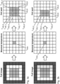
- Fig. 3 outlines schematically the determination of a hot spot for the ideal and non-ideal case:
- the first approach considers the background temperature, which is uninfluenced by the hot spot.
- the second approach focuses on the temperature in the immediate (or contiguous) region surrounding of the detected pixel with the maximal temperature.
- Figure 4 depicts schematically the evaluation of the background temperature
- correction functions are the core of the algorithm, which describe the hot spot size dependent error in temperature measured by the infrared camera. They can be derived from reference or basic measurements where thermocouples are additionally installed for the sake of comparison. With the purpose of generally valid correction functions, it is convenient to vary additionally the object (hot spot) and background temperature:
- the background temperature can be controlled in the measurements for the derivation of the correction functions.
- the resulting hot spot surrounding temperature is implicitly dependent on the background temperature. 4.
- the correction function f corr can be plotted against the number N for different hot spot and surrounding temperatures. Curve fitting is performed to have a global mathematical function which reveals the best fit of the measured errors in dependence on N for the considered range of hot spot and surrounding temperatures, see Fig. 6 . that shows measurement errors against number N of hot spot pixels and correction function, here as a linear function from a curve fitting.
- the different types of points represent measurements with different hot spot and background temperatures.
- the last step of the temperature correction algorithm is to calculate the corrected temperature:
- correction functions f corr can be provided, which actually results from a curve fitting of the error.
- the above described technique of temperature correction allows to improve the accuracy of hot spot temperature detection at a very low cost as only the simple algorithm has to be implemented in the micro controller of the sensor or in the central data aggregation unit. Neither additional complex optics is needed, nor a high-quality IR camera with better or high resolution.
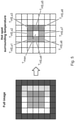
- FIG. 7 shows an exemplary spline interpolation for the non-ideal hot spot.
- interpolation increases the resolution of the image, which improves the characterization of the hot spot size and temperature as well as the surrounding/background temperature compared to the raw image in Fig. 2 b).
- interpolation methods are useful for the derivation of correction functions as well as for the temperature correction algorithm itself. In both cases, the interpolation is carried out beforehand and all further steps are proceeded with the interpolated image of better quality.
- Interpolation results in smooth linear functions between data points in each pixel of the raw image. Indeed, discontinuities, for example caused by a warm cable running through the cold background, can be only captured by the thermal image at the borders of the raw image pixels. In general, interpolation does not support to detect the exact boundaries of discontinuity in the raw image.
- the main benefit is that the interpolation leads to more accurate results. Especially, the temperature correction algorithm becomes less sensitive to changes in the number of hot spot pixels, which reduces oscillatory behaviour during an online temperature monitoring.
Description
- The present invention relates to an apparatus for hot spot sensing, a system for hot spot sensing, a low voltage, medium voltage or high voltage switchgear comprising such a system, and to a method for hot spot sensing.
- Infrared (IR) thermography (IRT), thermal imaging, and thermal video are examples of IR imaging science. Thermographic cameras usually detect radiation in the long-IR range of the electromagnetic spectrum (roughly 9,000-14,000 nanometers or 9-14 µm) and produce images of that radiation, called thermograms. Since IR radiation is emitted by all objects with a temperature above absolute zero according to the black body radiation law, thermography makes it possible to see an environment with or without visible illumination. The amount of radiation emitted by an object increases with temperature; therefore, thermography allows to see variations in temperature to be observed and also enables absolute temperatures to be determined from an assumption of an emissivity of a surface of an object.
-
US2018/283953A1 describes that flight based infrared imaging systems and related techniques, and in particular UAS based thermal imaging systems, are provided to improve the monitoring capabilities of such systems over conventional infrared monitoring systems. An infrared imaging system is configured to compensate for various environmental effects (e.g., position and/or strength of the sun, atmospheric effects) to provide high resolution and accuracy radiometric measurements of targets imaged by the infrared imaging system. An infrared imaging system is alternatively configured to monitor and determine environmental conditions, modify data received from infrared imaging systems and other systems, modify flight paths and other commands, and/or create a representation of the environment. - Infrared thermography is widely used for contactless temperature monitoring of hot spots in electrical equipment. High resolution IR cameras are typically applied for sporadic manual inspection and give a sufficiently precise absolute temperature value. Such high resolution cameras are too expensive to be permanently installed for online temperature monitoring in electrical equipment as, for example, the detection of critical hot spots to prevent overheating in switchgears. Low resolution infrared cameras, are at a price range that could find utility for this task, however do have limited image quality. In fact accuracy of the measured temperatures for hot spots is reduced and the accuracy of the size of the hot spot cannot be accurately determined.
- There is a need to address this issue.
- Therefore, it would be advantageous to have an improved technique to determine the size and temperature of hot spots in electrical equipment, such as low voltage, medium voltage and high voltage switchgear.
- The object of the present invention is solved with the subject matter of the independent claims, wherein further embodiments are incorporated in the dependent claims.
- In this manner, a low resolution camera can be used to monitor hot spot temperatures of electrical equipment. To put this another way, the apparatus increases the accuracy of low resolution IR cameras for hot spot temperature monitoring of electrical equipment.
- In other words, a hot spot size dependent correction algorithm is provided, that enables the error in hot spot temperature measurements to be reduced even when using low resolution infrared cameras.
- The temperature error can be further decreased through an increase of the resolution of the raw image by interpolations methods, before the correction is applied.
- Exemplary embodiments will be described in the following with reference to the following drawings:
-
Fig. 1 shows a detailed workflow of the utilization of an examples of an apparatus, a system, and a method for hot spot sensing; -
Fig. 2 shows an exemplar ideal hot spot; -
Fig. 3 shows examples of hot spot determination, for an ideal case in a) and for an non-ideal case in b); -
Fig. 4 shows an approach for evaluation of a surrounding temperature; -
Fig. 5 shows an approach for evaluation of a surrounding temperature; -
Fig. 6 shows an example of correction function as a function of the number of pixels in hot spots; -
Fig. 7 shows an example of spline interpolation of a non-ideal hot spot; and -
Fig. 8 shows an example of hot spot determination for the spline interpolated image ofFig. 7 . -
Figs. 1-8 relate to the operation of an apparatus, a system and a method for hot spot sensing. In an example, an apparatus is provided for hot spot sensing. The apparatus comprises an input unit, a processing unit, and an output unit. The input unit is configured to provide the processing unit with an image of an object that has a hot spot. Image data of the image comprises image data of the hot spot, and the image was acquired by a camera. The processing unit is configured to determine a number of pixels in the image corresponding to a size of the hot spot. The processing unit is configured to determine the maximal temperature and an average temperature for the hot spot. The determination of the average temperature comprises utilization of pixel values of the pixels in the image corresponding to the size of the hot spot and comprises utilization of the number of pixels in the image corresponding to the size of the hot spot. The processing unit is configured to determine a surrounding temperature in the image. The determination of the surrounding temperature comprises utilization of at least one pixel in the image different to the pixels in the image corresponding to the size of the hot spot. The processing unit is configured to determine a corrected temperature for the hot spot. The determination of the corrected temperature comprises utilization of a value of a correction factor, comprises utilization of the average temperature for the hot spot and comprises utilization of the surrounding temperature. - The apparatus finds utility in applications where an infrared camera measurement device can be installed to measure the temperature of hot spots. Examples are for low voltage, medium voltage and high voltage switchgears.
- In an example, the camera used to acquire the image is a low resolution camera. In an example, the camera has a sensor having 32x32 pixels. In an example, the camera has a sensor having 128x128 pixels. In an example, the camera has a sensor having 256x256 pixels. In an example, the camera has a sensor having 512 x 512 pixels. In an example, the camera has a sensor having 1024x1024 pixels.
- In an example, the camera used to acquire the image operates in the long infrared range. In an example, the camera used to acquire the image operates in the 9-14µm range.
- According to an example, the processing unit is configured to determine a pixel in the image corresponding to a maximum temperature of the hot spot. The pixels in the image corresponding to the size of the hot spot comprises the pixel in the image corresponding to the maximum temperature of the hot spot.
- According to an example, the processing unit is configured to determine the pixels in the image corresponding to the size of the hot spot as the pixels in the image that have a value within a threshold range of a value of the pixel determined to have a maximum temperature of the hot spot.
- According to an example, determination of the surrounding temperature comprises utilization of a number of at least one surrounding pixel in the image that is contiguous with the pixels in the image corresponding to the size of the hot spot and comprises utilization of at least one pixel value of the at least one surrounding pixel.
- According to an example, determination of the surrounding temperature comprises utilization of a number of at least one surrounding pixel in the image that is not contiguous with the pixels in the image corresponding to the size of the hot spot and comprises utilization of at least one pixel value of the at least one surrounding pixel.
- The correction factor has a plurality of possible values. The value of the correction factor used in the determination of the corrected temperature for the hot spot is determined as a function of the number of pixels in the image corresponding to the size of the hot spot.
- The plurality of possible values of the correction factor are determined on the basis of a plurality of calibration images of one or more hot spots acquired by the camera and/or by one more cameras that are substantially the same as the camera, and are determined on the basis of one or more measured temperatures or reference temperatures for the one or more hot spots.
- According to an example, a thermocouple is utilized to provide the measured temperatures.
- According to an example, determination of the plurality of possible values of the correction factor comprises for each calibration image of the plurality of calibration images a determination of a number of pixels in the calibration image corresponding to a size of the hot spot. The determination of the plurality of possible values of the correction factor also comprises for each calibration image of the plurality of calibration images a determination of an average temperature for the hot spot in the calibration image comprising a utilization of pixel values of the pixels in the calibration image corresponding to the size of the hot spot and the number of pixels in the calibration image corresponding to a size of the hot spot. The determination of the plurality of possible values of the correction factor also comprises for each calibration image of the plurality of calibration images a determination of a surrounding temperature in the calibration image comprising utilization of at least one pixel in the calibration image different to the pixels in the calibration image corresponding to the size of the hot spot.
- According to an example, the pixels in the calibration image corresponding to the size of the hot spot comprises a pixel in the calibration image corresponding to a maximum temperature of the hot spot. The pixels in the calibration image corresponding to the size of the hot spot are determined as the pixels in the calibration image that have a value within a threshold range of a value of the pixel determined to have the maximum temperature of the hot spot in the calibration image.
- According to an example, the determination of the plurality of possible values of the correction factor comprises for each calibration image of the plurality of calibration images a determination of an error value. The determination comprises a calculation of a first value as the measured or reference temperature for the hot spot subtracted from the average temperature for the hot spot in the calibration image and comprises a calculation of a second value as the surrounding temperature for the hot spot in the calibration image subtracted from the average temperature for the hot spot in the calibration image. The error value is then determined as the ratio of the first value to the second value.
- According to an example, determination of the corrected temperature comprises a multiplication of the correction factor with a difference between the average temperature for the hot spot in the image and the surrounding temperature in the image, and comprises a subtraction of the resulting temperature difference from the average temperature for the hot spot in the image.
- According to an example, upon the processing unit receiving the image from the input unit and prior to any further processing, the processing unit is configured to transform the image into an interpolated image for further processing.
- Thus, an apparatus can operate in an offline mode, where a camera acquires imagery that is then transferred to the apparatus that analyses that imagery to determine information relating to a hot spot as described above.
- However, the apparatus can be linked to a camera, and thereby form a system that can acquire imagery and analyse that imagery in real time, and therefore provide an accurate quantification of hots spots in electrical equipment, such as a switchgear in real time.
- As described, there is a workflow relating to the quantification of hot spots. Therefore, there is provided an method for hot spot sensing, the method in its basic step comprising:
- b) providing a processing unit with an image of an object that has a hot spot, wherein image data of the image comprises image data of the hot spot, and wherein the image was acquired by a camera;
- e) determining by the processing unit a number of pixels in the image corresponding to a size of the hot spot;
- f) determining by the processing unit an average temperature for the hot spot, the determining comprising utilizing pixel values of the pixels in the image corresponding to the size of the hot spot and the number of pixels in the image corresponding to the size of the hot spot;
- g) determining by the processing unit a surrounding temperature in the image, the determining comprising utilizing at least one pixel in the image different to the pixels in the image corresponding to the size of the hot spot;
- h) determining by the processing unit a corrected temperature for the hot spot, the determining comprising utilizing a value of a correction factor, the average temperature for the hot spot and the surrounding temperature.
- According to an example, the method comprises step d) determining by the processing unit a pixel in the image corresponding to a maximum temperature of the hot spot, and wherein in step e) the pixels in the image corresponding to the size of the hot spot comprises the pixel in the image corresponding to the maximum temperature of the hot spot.
- According to an example, step e) comprises the processing unit determining the pixels in the image corresponding to the size of the hot spot as the pixels in the image that have a value within a threshold range of a value of the pixel determined to have a maximum temperature of the hot spot.
- According to an example, step g) comprises utilizing a number of at least one surrounding pixel in the image that is contiguous with the pixels in the image corresponding to the size of the hot spot and at least one pixel value of the at least one surrounding pixel.
- According to an example, step g) comprises utilizing a number of at least one surrounding pixel in the image that is not contiguous with the pixels in the image corresponding to the size of the hot spot and at least one pixel value of the at least one surrounding pixel.
- In step h) the correction factor has a plurality of possible values, and step h) comprises determining the value of the correction factor as a function of the number of pixels in the image corresponding to the size of the hot spot.
- The method comprises step a) determining the plurality of possible values of the correction factor on the basis of a plurality of calibration images of one or more hot spots acquired by the camera and/or by one more cameras that are substantially the same as the camera, and on the basis of one or more measured temperatures or reference temperatures for the one or more hot spots.
- According to an example, a thermocouple is utilized to provide the measured temperatures.
- According to an example, step a) comprises determining for each calibration image of the plurality of calibration images a number of pixels in the calibration image corresponding to a size of the hot spot, determining an average temperature for the hot spot in the calibration image comprising utilizing pixel values of the pixels in the calibration image corresponding to the size of the hot spot and the number of pixels in the calibration image corresponding to a size of the hot spot, and determining a surrounding temperature in the calibration image comprising utilizing at least one pixel in the calibration image different to the pixels in the calibration image corresponding to the hot spot.
- According to an example, in step a) the pixels in the calibration image corresponding to the size of the hot spot comprises a pixel in the calibration image corresponding to a maximum temperature of the hot spot, and wherein step a) comprises determining the pixels in the calibration image corresponding to the size of the hot spot as the pixels in the calibration image that have a value within a threshold range of a value of the pixel determined to have the maximum temperature of the hot spot in the calibration image.
- According to an example, step a) comprises determining for each calibration image of the plurality of calibration images an error value, the determining comprising calculating a first value as the measured or reference temperature for the hot spot subtracted from the average temperature for the hot spot in the calibration image and calculating a second value as the surrounding temperature for the hot spot in the calibration image subtracted from the average temperature for the hot spot in the calibration image, and wherein step a) comprises determining the error value as the ratio of the first value to the second value.
- According to an example, step h) comprises multiplying the correction factor with a difference between the average temperature for the hot spot in the image and the surrounding temperature in the image, and subtracting this from the average temperature for the hot spot in the image.
- According to an example, the method comprises step c) transforming by the processing unit the image into an interpolated image for further processing.
- Thus, the above described apparatus, system and method addresses the issue of the accurate determination of a precise absolute temperature value for small hot spots that are detected by low-resolution IR camera, which would otherwise not be achievable with a low resolution camera but would require a high resolution and expensive IR camera.
- The apparatus, system and method has overcome the following problems
- [1] The lower resolution makes it more difficult to distinguish between the temperature of the hot spot and of its background. A hot spot pixel with the maximal measured temperature may represent to some extent the temperature of the background. This effect is more pronounced, the higher the temperature difference becomes between hot spot and background. Thus, low-resolution IR cameras deliver a further reduced accuracy, especially for small hot spots in the vicinity of a cold background.
- [2] The usage of wide-angle lens implies the fisheye effect for low-resolution IR cameras which means that equal-sized objects of same temperature are resolved by varying pixel numbers depending on their position in the image. The more the object is positioned away from the middle position, the less accurate the measured temperature becomes due to the reduced number of pixels.
- [1] and [2] are characteristic for low-resolution IR cameras, and can normally only be mitigated by selecting high-quality high resolution IR cameras, which has until now made permanent installation unattractive. However, the currently described techniques enable low resolution cameras to be used effectively and cost effectively in permanently installed locations for monitoring electrical equipment.
- As discussed above, the above problems have been solved by using a correction algorithm, which compensates for the temperature error for hot spots during an image processing step. The correction algorithm enables the accuracy of temperatures from low resolution IR cameras to be improved, and where further improvement in the accuracy is provided by applying interpolation methods.
- Further detail on specific embodiments is now described, again with reference to
Figs. 1-8 . - In the situation when there are several hot spots in a global image, a partitioning algorithm segregates the measured image into component parts. Each part represents one independent hot spot. Below, the solution is explained for one hot spot.
- The temperature correction algorithm consists of four steps, as shown in the flow chart in
Fig. 1 : - [1] Detection of image pixel with maximal temperature. The algorithm finds the image pixel showing the highest absolute temperature value.
- [2] Determination of hot spot size and temperature. The hot spot size is determined by counting the image pixels which fulfil a predefined hot spot condition in the vicinity of maximal temperature. The mean value of all detected pixels gives the hot spot temperature.
- [3] Determination of surrounding/background temperature. The higher the difference between surrounding/background and the hot spot temperature, the more has the algorithm to compensate.
- [4] Correction function
- (a) Derivation - Measurements are performed to evaluate the hot spot size-dependent temperature error. The correction functions are derived by curve fitting of the error.
- (b) Application - The correction function of the algorithm gives the corrected hot spot temperature as output after steps [1]-[3].
- Interpolation methods can be applied on the raw images to reach a better spatial resolution of the hot spot area and size.
- The solution aims at using low-resolution IR cameras for online temperature monitoring of hot spots, where the algorithm can be implemented in the micro-controller of the sensor or in the central data aggregation unit.
-
Figure 2 shows an ideal hot spot. In the middle of the image is the pixel with maximal temperature, but the hot spot definition also includes the neighbouring area of this pixel. Influence of hot spot is obvious in the transition region while the background remains unaffected. It has been established that the maximal temperature is in good agreement with the real temperature for hot spot pixel numbers N ≥ 9, where N is the total number of detected hot spot pixels. Therefore, the amount of correction reduces for N ≥ 9 in the derived correction functions. InFig. 2 , the pixel, representing the maximal temperature, is surrounded by pixels with about the same temperature. This is the ideal case. The distribution of the hot spot pixels can also be taken into account for an error compensation, but can remain unconsidered for the sake of simplicity. Thus, in the following in addition to providing an compensation function that varies as a function of the number of pixels in the hot spot, with additional experimental data the compensation function can be determined taking into account the distributions of the hot spot pixels. -
Fig. 3 outlines schematically the determination of a hot spot for the ideal and non-ideal case: - 1. The first step is to identify the pixel with the maximal temperature Tmax for the full image. Here, this full image only represents a hot spot which can be already segregated from a larger image as mentioned before.
- 2. A hot spot condition is defined to detect all image pixels which belong to the hot spot, for instance

- 3. By applying the hot spot conditions, all hot spot pixels THS,i can be detected with i = 1...N where N denotes the total number of hot spot pixels. Then, the hot spot temperature THS follows from the average temperature of all detected pixels

- 4. Finally, the number N as well as the average temperature THS describes the hot spot in size and temperature.
- For the evaluation of the surrounding temperature, two cases are distinguished. The first approach considers the background temperature, which is uninfluenced by the hot spot. The second approach focuses on the temperature in the immediate (or contiguous) region surrounding of the detected pixel with the maximal temperature.
-
Figure 4 depicts schematically the evaluation of the background temperature: - 1. The background temperature is represented by the image pixels which are in close proximity to the hot spot, but are unaffected. Thus, the background area encloses a connected border around the hot spot for determination of the background temperature.
- 2. The average temperature TBG of the background is given by

- It has been established that the influence of surrounding temperature can be also estimated in the close proximity of the hot spot. In this approach, the surrounding temperature is affected by the hot spot and the difference to the maximal measured temperature gives a quantity relating to how accurate the measurement of the hot spot temperature is. If the difference goes to zero, the hot spot surrounding temperature coincides more and more with the maximal temperature and the error becomes negligible.
Figure 5 shows qualitatively the determination of the hot spot surrounding temperature THS,s : - 1. The eight image pixels around the pixel with maximal temperature yield the surrounding temperature THS,s of the hot spot.
- 2. The hot spot surrounding temperature THS,s can be determined by

- 3. In the correction functions, the hot spot surrounding temperature THS,s represents the amount of correction, which is needed due to the difference of maximal temperature and its immediate surrounding.
- The correction functions are the core of the algorithm, which describe the hot spot size dependent error in temperature measured by the infrared camera. They can be derived from reference or basic measurements where thermocouples are additionally installed for the sake of comparison. With the purpose of generally valid correction functions, it is convenient to vary additionally the object (hot spot) and background temperature:
- 1. The maximal temperature Tmax or the hot spot temperature THS can be taken as measured hot spot temperature THS,meas to derive the correction functions. Note that the temperature correction algorithm should be applied for the same choice of measured temperature.
- 2. The error between real temperature THS,real and measured temperature THS,meas can be written as

- 3. Two approaches are introduced to consider the surrounding of the hot spot which lead to different correction functions fcorr. The surrounding temperature TSR can be represented by the background temperature TSR = TBG or by the hot spot surrounding temperature TSR = THs,s.
- However, the background temperature can be controlled in the measurements for the derivation of the correction functions. The resulting hot spot surrounding temperature is implicitly dependent on the background temperature. 4. By evaluating the measurements, the correction function fcorr can be plotted against the number N for different hot spot and surrounding temperatures. Curve fitting is performed to have a global mathematical function which reveals the best fit of the measured errors in dependence on N for the considered range of hot spot and surrounding temperatures, see
Fig. 6 . that shows measurement errors against number N of hot spot pixels and correction function, here as a linear function from a curve fitting. The different types of points represent measurements with different hot spot and background temperatures. - The last step of the temperature correction algorithm is to calculate the corrected temperature:
As explained above, correction functions fcorr can be provided, which actually results from a curve fitting of the error. A corrected temperature can then be calculated directly from
- Thus in this manner, the above described technique of temperature correction allows to improve the accuracy of hot spot temperature detection at a very low cost as only the simple algorithm has to be implemented in the micro controller of the sensor or in the central data aggregation unit. Neither additional complex optics is needed, nor a high-quality IR camera with better or high resolution.
- Interpolation methods can be used to increase image quality.
Fig. 7 shows an exemplary spline interpolation for the non-ideal hot spot. - As outlined in
Fig. 8 , interpolation increases the resolution of the image, which improves the characterization of the hot spot size and temperature as well as the surrounding/background temperature compared to the raw image inFig. 2 b). - The application of interpolation methods is useful for the derivation of correction functions as well as for the temperature correction algorithm itself. In both cases, the interpolation is carried out beforehand and all further steps are proceeded with the interpolated image of better quality.
- Interpolation results in smooth linear functions between data points in each pixel of the raw image. Indeed, discontinuities, for example caused by a warm cable running through the cold background, can be only captured by the thermal image at the borders of the raw image pixels. In general, interpolation does not support to detect the exact boundaries of discontinuity in the raw image.
- The main benefit is that the interpolation leads to more accurate results. Especially, the temperature correction algorithm becomes less sensitive to changes in the number of hot spot pixels, which reduces oscillatory behaviour during an online temperature monitoring.
- While the invention has been illustrated and described in detail in the drawings and foregoing description, such illustration and description are to be considered illustrative or exemplary and not restrictive. The invention is not limited to the disclosed embodiments. Other variations to the disclosed embodiments, which are within the scope of the appended claims, can be understood and effected by those skilled in the art.
Claims (24)
- An apparatus for hot spot sensing, the apparatus comprising:- an input unit;- a processing unit; and- an output unit;wherein, the input unit is configured to provide the processing unit with an image of an object that has a hot spot, wherein image data of the image comprises image data of the hot spot, and wherein the image was acquired by a camera;wherein, the processing unit is configured to determine a number of pixels in the image corresponding to a size of the hot spot;wherein, the processing unit is configured to determine an average temperature for the hot spot, the determination comprising utilization of pixel values of the pixels in the image corresponding to the size of the hot spot and the number of pixels in the image corresponding to the size of the hot spot;wherein, the processing unit is configured to determine a surrounding temperature in the image, the determination comprising utilization of at least one pixel in the image different to the pixels in the image corresponding to the size of the hot spot;wherein, the processing unit is configured to determine a corrected temperature for the hot spot, the determination comprising utilization of a value of a correction factor, the average temperature for the hot spot and the surrounding temperature;wherein the correction factor has a plurality of possible values, and wherein the value of the correction factor used in the determination of the corrected temperature for the hot spot is determined as a function of the number of pixels in the image corresponding to the size of the hot spot; andwherein the plurality of possible values of the correction factor are determined on the basis of a plurality of calibration images of one or more hot spots acquired by the camera and/or by one more cameras that are substantially the same as the camera, and on the basis of one or more measured temperatures or reference temperatures for the one or more hot spots.
- Apparatus according to claim 1, wherein the processing unit is configured to determine a pixel in the image corresponding to a maximum temperature of the hot spot, and wherein the pixels in the image corresponding to the size of the hot spot comprise the pixel in the image corresponding to the maximum temperature of the hot spot.
- Apparatus according to claim 2, wherein the processing unit is configured to determine the pixels in the image corresponding to the size of the hot spot as the pixels in the image that have a value within a threshold range of a value of the pixel determined to have a maximum temperature of the hot spot.
- Apparatus according to any of claims 1-3, wherein determination of the surrounding temperature comprises utilization of a number of at least one surrounding pixel in the image that is contiguous with the pixels in the image corresponding to the size of the hot spot and at least one pixel value of the at least one surrounding pixel.
- Apparatus according to any of claims 1-3, wherein determination of the surrounding temperature comprises utilization of a number of at least one surrounding pixel in the image that is not contiguous with the pixels in the image corresponding to the size of the hot spot and at least one pixel value of the at least one surrounding pixel.
- Apparatus according to any of claims 1-5, wherein a thermocouple is utilized to provide the measured temperatures.
- Apparatus according to any of claims 1-6, wherein determination of the plurality of possible values of the correction factor comprises for each calibration image of the plurality of calibration images a determination of a number of pixels in the calibration image corresponding to a size of the hot spot, a determination of an average temperature for the hot spot in the calibration image comprising a utilization of pixel values of the pixels in the calibration image corresponding to the size of the hot spot and the number of pixels in the calibration image corresponding to a size of the hot spot, and a determination of a surrounding temperature in the calibration image comprising utilization of at least one pixel in the calibration image different to the pixels in the calibration image corresponding to the size of the hot spot.
- Apparatus according to claim 7, wherein the pixels in the calibration image corresponding to the size of the hot spot comprise a pixel in the calibration image corresponding to a maximum temperature of the hot spot, and wherein the pixels in the calibration image corresponding to the size of the hot spot are determined as the pixels in the calibration image that have a value within a threshold range of a value of the pixel determined to have the maximum temperature of the hot spot in the calibration image.
- Apparatus according to any of claims 6-8, wherein the determination of the plurality of possible values of the correction factor comprises for each calibration image of the plurality of calibration images a determination of an error value, the determination comprising a calculation of a first value as the measured or reference temperature for the hot spot subtracted from the average temperature for the hot spot in the calibration image and a calculation of a second value as the surrounding temperature for the hot spot in the calibration image subtracted from the average temperature for the hot spot in the calibration image, and wherein the error value is determined as the ratio of the first value to the second value.
- Apparatus according to any of claims 1-9, wherein determination of the corrected temperature comprises a multiplication of the correction factor with a difference between the average temperature for the hot spot in the image and the surrounding temperature in the image, and a subtraction of this from the average temperature for the hot spot in the image.
- Apparatus according to any of claims 1-10, wherein upon the processing unit receiving the image from the input unit and prior to any further processing, the processing unit is configured to transform the image into an interpolated image for further processing.
- A system for hot spot sensing, the system comprising:- an apparatus according to any of claims 1-11; and- a camera
wherein, the camera is configured to acquire the image of an object that has a hot spot. - A low voltage, medium voltage or high voltage switchgear, comprising at least one system according to claim 12, wherein the object that has a hot spot is part of the switchgear.
- A method for hot spot sensing, the method comprising:b) providing a processing unit with an image of an object that has a hot spot, wherein image data of the image comprises image data of the hot spot, and wherein the image was acquired by a camera;e) determining by the processing unit a number of pixels in the image corresponding to a size of the hot spot;f) determining by the processing unit an average temperature for the hot spot, the determining comprising utilizing pixel values of the pixels in the image corresponding to the size of the hot spot and the number of pixels in the image corresponding to the size of the hot spot;g) determining by the processing unit a surrounding temperature in the image, the determining comprising utilizing at least one pixel in the image different to the pixels in the image corresponding to the size of the hot spot; andh) determining by the processing unit a corrected temperature for the hot spot, the determining comprising utilizing a value of a correction factor, the average temperature for the hot spot and the surrounding temperature;wherein in step h) the correction factor has a plurality of possible values, and wherein step h) comprises determining the value of the correction factor as a function of the number of pixels in the image corresponding to the size of the hot spot; andwherein the method comprises step a) determining the plurality of possible values of the correction factor on the basis of a plurality of calibration images of one or more hot spots acquired by the camera and/or by one more cameras that are substantially the same as the camera, and on the basis of one or more measured temperatures or reference temperatures for the one or more hot spots.
- Method according to claim 14, wherein the method comprises step d) determining by the processing unit a pixel in the image corresponding to a maximum temperature of the hot spot, and wherein in step e) the pixels in the image corresponding to the size of the hot spot comprise the pixel in the image corresponding to the maximum temperature of the hot spot.
- Method according to claim 15, wherein step e) comprises the processing unit determining the pixels in the image corresponding to the size of the hot spot as the pixels in the image that have a value within a threshold range of a value of the pixel determined to have a maximum temperature of the hot spot.
- Method according to any of claims 14-16, wherein step g) comprises utilizing a number of at least one surrounding pixel in the image that is contiguous with the pixels in the image corresponding to the size of the hot spot and at least one pixel value of the at least one surrounding pixel.
- Method according to any of claims 14-16, wherein step g) comprises utilizing a number of at least one surrounding pixel in the image that is not contiguous with the pixels in the image corresponding to the size of the hot spot and at least one pixel value of the at least one surrounding pixel.
- Method according to any of claims 14-18, wherein a thermocouple is utilized to provide the measured temperatures.
- Method according to any of claims 14-19, wherein stepa) comprises determining for each calibration image of the plurality of calibration images a number of pixels in the calibration image corresponding to a size of the hot spot, determining an average temperature for the hot spot in the calibration image comprising utilizing pixel values of the pixels in the calibration image corresponding to the size of the hot spot and the number of pixels in the calibration image corresponding to a size of the hot spot, and determining a surrounding temperature in the calibration image comprising utilizing at least one pixel in the calibration image different to the pixels in the calibration image corresponding to the hot spot.
- Method according to claim 20, wherein in step a) the pixels in the calibration image corresponding to the size of the hot spot comprise a pixel in the calibration image corresponding to a maximum temperature of the hot spot, and wherein step a) comprises determining the pixels in the calibration image corresponding to the size of the hot spot as the pixels in the calibration image that have a value within a threshold range of a value of the pixel determined to have the maximum temperature of the hot spot in the calibration image.
- Method according to any of claims 19-21, wherein stepa) comprises determining for each calibration image of the plurality of calibration images an error value, the determining comprising calculating a first value as the measured or reference temperature for the hot spot subtracted from the average temperature for the hot spot in the calibration image and calculating a second value as the surrounding temperature for the hot spot in the calibration image subtracted from the average temperature for the hot spot in the calibration image, and wherein step a) comprises determining the error value as the ratio of the first value to the second value.
- Method according to any of claims 14-22, wherein step h) comprises multiplying the correction factor with a difference between the average temperature for the hot spot in the image and the surrounding temperature in the image, and subtracting this from the average temperature for the hot spot in the image.
- Method according to any of claims 14-23, wherein the method comprises step c) transforming by the processing unit the image into an interpolated image for further processing.
Priority Applications (4)
| Application Number | Priority Date | Filing Date | Title |
|---|---|---|---|
| EP19165287.4A EP3716205B1 (en) | 2019-03-26 | 2019-03-26 | An apparatus for hot spot sensing |
| PCT/EP2020/057835 WO2020193422A1 (en) | 2019-03-26 | 2020-03-20 | An apparatus for hot spot sensing |
| CN202080024274.8A CN113678165A (en) | 2019-03-26 | 2020-03-20 | Apparatus for hotspot sensing |
| US17/483,834 US20220011164A1 (en) | 2019-03-26 | 2021-09-24 | Apparatus for hot spot sensing |
Applications Claiming Priority (1)
| Application Number | Priority Date | Filing Date | Title |
|---|---|---|---|
| EP19165287.4A EP3716205B1 (en) | 2019-03-26 | 2019-03-26 | An apparatus for hot spot sensing |
Publications (2)
| Publication Number | Publication Date |
|---|---|
| EP3716205A1 EP3716205A1 (en) | 2020-09-30 |
| EP3716205B1 true EP3716205B1 (en) | 2022-02-23 |
Family
ID=66175136
Family Applications (1)
| Application Number | Title | Priority Date | Filing Date |
|---|---|---|---|
| EP19165287.4A Active EP3716205B1 (en) | 2019-03-26 | 2019-03-26 | An apparatus for hot spot sensing |
Country Status (4)
| Country | Link |
|---|---|
| US (1) | US20220011164A1 (en) |
| EP (1) | EP3716205B1 (en) |
| CN (1) | CN113678165A (en) |
| WO (1) | WO2020193422A1 (en) |
Families Citing this family (4)
| Publication number | Priority date | Publication date | Assignee | Title |
|---|---|---|---|---|
| EP3706269B1 (en) * | 2019-03-07 | 2022-06-29 | ABB Schweiz AG | Artificial intelligence monitoring system using infrared images to identify hotspots in a switchgear |
| CN113916383B (en) * | 2021-09-29 | 2023-11-21 | 杭州微影软件有限公司 | Thermal imaging temperature measurement method and device and electronic equipment |
| EP4212838A1 (en) * | 2022-01-14 | 2023-07-19 | Abb Schweiz Ag | System for monitoring a switchgear |
| EP4266015A1 (en) * | 2022-04-21 | 2023-10-25 | Abb Schweiz Ag | System for monitoring a switchgear |
Family Cites Families (8)
| Publication number | Priority date | Publication date | Assignee | Title |
|---|---|---|---|---|
| US8531562B2 (en) * | 2004-12-03 | 2013-09-10 | Fluke Corporation | Visible light and IR combined image camera with a laser pointer |
| US7661876B2 (en) * | 2007-11-14 | 2010-02-16 | Fluke Corporation | Infrared target temperature correction system and method |
| ATE534175T1 (en) * | 2009-07-27 | 2011-12-15 | Abb Research Ltd | POWER SWITCHGEAR |
| US9224278B2 (en) * | 2011-04-18 | 2015-12-29 | Xerox Corporation | Automated method and system for detecting the presence of a lit cigarette |
| KR101531879B1 (en) * | 2012-01-17 | 2015-06-26 | 티.비.티. 주식회사 | Infrared image processing apparatus |
| MX340152B (en) * | 2013-12-19 | 2016-06-08 | Kaplun Mucharrafille Margarita | System and method for calibrating and/or characterizing instruments for measuring the temperature by telemetry. |
| CN108603790B (en) * | 2015-12-09 | 2020-09-25 | 菲力尔系统公司 | Thermal imaging system and method based on unmanned aerial vehicle system |
| JP2019526304A (en) * | 2016-06-29 | 2019-09-19 | ニラマイ・ヘルス・アナリティックス・ピーブイティー・エルティーディ | Classification of hormone receptor status in malignant neoplastic tissue by chest thermography image |
-
2019
- 2019-03-26 EP EP19165287.4A patent/EP3716205B1/en active Active
-
2020
- 2020-03-20 WO PCT/EP2020/057835 patent/WO2020193422A1/en active Application Filing
- 2020-03-20 CN CN202080024274.8A patent/CN113678165A/en active Pending
-
2021
- 2021-09-24 US US17/483,834 patent/US20220011164A1/en active Pending
Also Published As
| Publication number | Publication date |
|---|---|
| EP3716205A1 (en) | 2020-09-30 |
| WO2020193422A1 (en) | 2020-10-01 |
| CN113678165A (en) | 2021-11-19 |
| US20220011164A1 (en) | 2022-01-13 |
Similar Documents
| Publication | Publication Date | Title |
|---|---|---|
| EP3716205B1 (en) | An apparatus for hot spot sensing | |
| US9804031B2 (en) | Apparatus and method to calculate energy dissipated from an object | |
| Budzier et al. | Calibration of uncooled thermal infrared cameras | |
| US10116885B2 (en) | Systems and approaches for repeated thermal imaging determinations | |
| CN110793635B (en) | Thermal imaging temperature measurement method and device and terminal equipment | |
| CA2252057C (en) | Method for determining pressure | |
| US9696210B2 (en) | Extended temperature range mapping process of a furnace enclosure using various device settings | |
| US11128818B2 (en) | Thermal image processing system and method | |
| CN112798110A (en) | Calibration fitting-based temperature detection method for infrared thermal imaging equipment | |
| US20150355030A1 (en) | Equipment and method for intensity-temperature transformation of imaging system | |
| CN113834571A (en) | Target temperature measurement method, device and temperature measurement system | |
| WO2019069994A1 (en) | Airflow measuring device | |
| Kettelgerdes et al. | Correlating intrinsic parameters and sharpness for condition monitoring of automotive imaging sensors | |
| JP4742883B2 (en) | Far-infrared imaging device and output value correction method | |
| CN111207833B (en) | Temperature measurement method based on image data normalization technology | |
| Whitenton | An introduction for machining researchers to measurement uncertainty sources in thermal images of metal cutting | |
| WO2001096814A2 (en) | System and method for converting analog data to digital data | |
| Muniz et al. | Non-contact measurement of angle of view between the inspected surface and the thermal imager | |
| CN110111277B (en) | Planar thermal image repairing method and device | |
| Dziarski et al. | Effect of unsharpness on the result of thermovision diagnostics of electronic components | |
| Vidas et al. | Ad hoc radiometric calibration of a thermal-infrared camera | |
| US11761821B2 (en) | System and method for thermal imaging | |
| KR102639542B1 (en) | Method and apparatus for detecting temperature of fever detection system using thermal image camera | |
| Soleimanijavid et al. | Smart Low-cost Thermal Imaging Acquisition Towards Personal Comfort Prediction | |
| CN115507961A (en) | Variable-environment-temperature infrared measurement calibration method and device |
Legal Events
| Date | Code | Title | Description |
|---|---|---|---|
| PUAI | Public reference made under article 153(3) epc to a published international application that has entered the european phase |
Free format text: ORIGINAL CODE: 0009012 |
|
| STAA | Information on the status of an ep patent application or granted ep patent |
Free format text: STATUS: THE APPLICATION HAS BEEN PUBLISHED |
|
| AK | Designated contracting states |
Kind code of ref document: A1 Designated state(s): AL AT BE BG CH CY CZ DE DK EE ES FI FR GB GR HR HU IE IS IT LI LT LU LV MC MK MT NL NO PL PT RO RS SE SI SK SM TR |
|
| AX | Request for extension of the european patent |
Extension state: BA ME |
|
| STAA | Information on the status of an ep patent application or granted ep patent |
Free format text: STATUS: REQUEST FOR EXAMINATION WAS MADE |
|
| 17P | Request for examination filed |
Effective date: 20210212 |
|
| RBV | Designated contracting states (corrected) |
Designated state(s): AL AT BE BG CH CY CZ DE DK EE ES FI FR GB GR HR HU IE IS IT LI LT LU LV MC MK MT NL NO PL PT RO RS SE SI SK SM TR |
|
| GRAP | Despatch of communication of intention to grant a patent |
Free format text: ORIGINAL CODE: EPIDOSNIGR1 |
|
| STAA | Information on the status of an ep patent application or granted ep patent |
Free format text: STATUS: GRANT OF PATENT IS INTENDED |
|
| INTG | Intention to grant announced |
Effective date: 20211029 |
|
| GRAS | Grant fee paid |
Free format text: ORIGINAL CODE: EPIDOSNIGR3 |
|
| GRAA | (expected) grant |
Free format text: ORIGINAL CODE: 0009210 |
|
| STAA | Information on the status of an ep patent application or granted ep patent |
Free format text: STATUS: THE PATENT HAS BEEN GRANTED |
|
| AK | Designated contracting states |
Kind code of ref document: B1 Designated state(s): AL AT BE BG CH CY CZ DE DK EE ES FI FR GB GR HR HU IE IS IT LI LT LU LV MC MK MT NL NO PL PT RO RS SE SI SK SM TR |
|
| RAP3 | Party data changed (applicant data changed or rights of an application transferred) |
Owner name: ABB SCHWEIZ AG |
|
| REG | Reference to a national code |
Ref country code: GB Ref legal event code: FG4D |
|
| REG | Reference to a national code |
Ref country code: CH Ref legal event code: EP |
|
| REG | Reference to a national code |
Ref country code: AT Ref legal event code: REF Ref document number: 1471042 Country of ref document: AT Kind code of ref document: T Effective date: 20220315 |
|
| REG | Reference to a national code |
Ref country code: IE Ref legal event code: FG4D |
|
| REG | Reference to a national code |
Ref country code: DE Ref legal event code: R096 Ref document number: 602019011761 Country of ref document: DE |
|
| REG | Reference to a national code |
Ref country code: LT Ref legal event code: MG9D |
|
| REG | Reference to a national code |
Ref country code: NL Ref legal event code: MP Effective date: 20220223 |
|
| REG | Reference to a national code |
Ref country code: AT Ref legal event code: MK05 Ref document number: 1471042 Country of ref document: AT Kind code of ref document: T Effective date: 20220223 |
|
| PG25 | Lapsed in a contracting state [announced via postgrant information from national office to epo] |
Ref country code: SE Free format text: LAPSE BECAUSE OF FAILURE TO SUBMIT A TRANSLATION OF THE DESCRIPTION OR TO PAY THE FEE WITHIN THE PRESCRIBED TIME-LIMIT Effective date: 20220223 Ref country code: RS Free format text: LAPSE BECAUSE OF FAILURE TO SUBMIT A TRANSLATION OF THE DESCRIPTION OR TO PAY THE FEE WITHIN THE PRESCRIBED TIME-LIMIT Effective date: 20220223 Ref country code: PT Free format text: LAPSE BECAUSE OF FAILURE TO SUBMIT A TRANSLATION OF THE DESCRIPTION OR TO PAY THE FEE WITHIN THE PRESCRIBED TIME-LIMIT Effective date: 20220623 Ref country code: NO Free format text: LAPSE BECAUSE OF FAILURE TO SUBMIT A TRANSLATION OF THE DESCRIPTION OR TO PAY THE FEE WITHIN THE PRESCRIBED TIME-LIMIT Effective date: 20220523 Ref country code: NL Free format text: LAPSE BECAUSE OF FAILURE TO SUBMIT A TRANSLATION OF THE DESCRIPTION OR TO PAY THE FEE WITHIN THE PRESCRIBED TIME-LIMIT Effective date: 20220223 Ref country code: LT Free format text: LAPSE BECAUSE OF FAILURE TO SUBMIT A TRANSLATION OF THE DESCRIPTION OR TO PAY THE FEE WITHIN THE PRESCRIBED TIME-LIMIT Effective date: 20220223 Ref country code: HR Free format text: LAPSE BECAUSE OF FAILURE TO SUBMIT A TRANSLATION OF THE DESCRIPTION OR TO PAY THE FEE WITHIN THE PRESCRIBED TIME-LIMIT Effective date: 20220223 Ref country code: ES Free format text: LAPSE BECAUSE OF FAILURE TO SUBMIT A TRANSLATION OF THE DESCRIPTION OR TO PAY THE FEE WITHIN THE PRESCRIBED TIME-LIMIT Effective date: 20220223 Ref country code: BG Free format text: LAPSE BECAUSE OF FAILURE TO SUBMIT A TRANSLATION OF THE DESCRIPTION OR TO PAY THE FEE WITHIN THE PRESCRIBED TIME-LIMIT Effective date: 20220523 |
|
| PG25 | Lapsed in a contracting state [announced via postgrant information from national office to epo] |
Ref country code: PL Free format text: LAPSE BECAUSE OF FAILURE TO SUBMIT A TRANSLATION OF THE DESCRIPTION OR TO PAY THE FEE WITHIN THE PRESCRIBED TIME-LIMIT Effective date: 20220223 Ref country code: LV Free format text: LAPSE BECAUSE OF FAILURE TO SUBMIT A TRANSLATION OF THE DESCRIPTION OR TO PAY THE FEE WITHIN THE PRESCRIBED TIME-LIMIT Effective date: 20220223 Ref country code: GR Free format text: LAPSE BECAUSE OF FAILURE TO SUBMIT A TRANSLATION OF THE DESCRIPTION OR TO PAY THE FEE WITHIN THE PRESCRIBED TIME-LIMIT Effective date: 20220524 Ref country code: FI Free format text: LAPSE BECAUSE OF FAILURE TO SUBMIT A TRANSLATION OF THE DESCRIPTION OR TO PAY THE FEE WITHIN THE PRESCRIBED TIME-LIMIT Effective date: 20220223 Ref country code: AT Free format text: LAPSE BECAUSE OF FAILURE TO SUBMIT A TRANSLATION OF THE DESCRIPTION OR TO PAY THE FEE WITHIN THE PRESCRIBED TIME-LIMIT Effective date: 20220223 |
|
| PG25 | Lapsed in a contracting state [announced via postgrant information from national office to epo] |
Ref country code: IS Free format text: LAPSE BECAUSE OF FAILURE TO SUBMIT A TRANSLATION OF THE DESCRIPTION OR TO PAY THE FEE WITHIN THE PRESCRIBED TIME-LIMIT Effective date: 20220623 |
|
| PG25 | Lapsed in a contracting state [announced via postgrant information from national office to epo] |
Ref country code: SM Free format text: LAPSE BECAUSE OF FAILURE TO SUBMIT A TRANSLATION OF THE DESCRIPTION OR TO PAY THE FEE WITHIN THE PRESCRIBED TIME-LIMIT Effective date: 20220223 Ref country code: SK Free format text: LAPSE BECAUSE OF FAILURE TO SUBMIT A TRANSLATION OF THE DESCRIPTION OR TO PAY THE FEE WITHIN THE PRESCRIBED TIME-LIMIT Effective date: 20220223 Ref country code: RO Free format text: LAPSE BECAUSE OF FAILURE TO SUBMIT A TRANSLATION OF THE DESCRIPTION OR TO PAY THE FEE WITHIN THE PRESCRIBED TIME-LIMIT Effective date: 20220223 Ref country code: EE Free format text: LAPSE BECAUSE OF FAILURE TO SUBMIT A TRANSLATION OF THE DESCRIPTION OR TO PAY THE FEE WITHIN THE PRESCRIBED TIME-LIMIT Effective date: 20220223 Ref country code: DK Free format text: LAPSE BECAUSE OF FAILURE TO SUBMIT A TRANSLATION OF THE DESCRIPTION OR TO PAY THE FEE WITHIN THE PRESCRIBED TIME-LIMIT Effective date: 20220223 Ref country code: CZ Free format text: LAPSE BECAUSE OF FAILURE TO SUBMIT A TRANSLATION OF THE DESCRIPTION OR TO PAY THE FEE WITHIN THE PRESCRIBED TIME-LIMIT Effective date: 20220223 |
|
| REG | Reference to a national code |
Ref country code: CH Ref legal event code: PL |
|
| REG | Reference to a national code |
Ref country code: DE Ref legal event code: R097 Ref document number: 602019011761 Country of ref document: DE |
|
| PG25 | Lapsed in a contracting state [announced via postgrant information from national office to epo] |
Ref country code: MC Free format text: LAPSE BECAUSE OF FAILURE TO SUBMIT A TRANSLATION OF THE DESCRIPTION OR TO PAY THE FEE WITHIN THE PRESCRIBED TIME-LIMIT Effective date: 20220223 Ref country code: AL Free format text: LAPSE BECAUSE OF FAILURE TO SUBMIT A TRANSLATION OF THE DESCRIPTION OR TO PAY THE FEE WITHIN THE PRESCRIBED TIME-LIMIT Effective date: 20220223 |
|
| REG | Reference to a national code |
Ref country code: BE Ref legal event code: MM Effective date: 20220331 |
|
| PLBE | No opposition filed within time limit |
Free format text: ORIGINAL CODE: 0009261 |
|
| STAA | Information on the status of an ep patent application or granted ep patent |
Free format text: STATUS: NO OPPOSITION FILED WITHIN TIME LIMIT |
|
| PG25 | Lapsed in a contracting state [announced via postgrant information from national office to epo] |
Ref country code: LU Free format text: LAPSE BECAUSE OF NON-PAYMENT OF DUE FEES Effective date: 20220326 Ref country code: LI Free format text: LAPSE BECAUSE OF NON-PAYMENT OF DUE FEES Effective date: 20220331 Ref country code: IE Free format text: LAPSE BECAUSE OF NON-PAYMENT OF DUE FEES Effective date: 20220326 Ref country code: CH Free format text: LAPSE BECAUSE OF NON-PAYMENT OF DUE FEES Effective date: 20220331 |
|
| 26N | No opposition filed |
Effective date: 20221124 |
|
| PG25 | Lapsed in a contracting state [announced via postgrant information from national office to epo] |
Ref country code: SI Free format text: LAPSE BECAUSE OF FAILURE TO SUBMIT A TRANSLATION OF THE DESCRIPTION OR TO PAY THE FEE WITHIN THE PRESCRIBED TIME-LIMIT Effective date: 20220223 Ref country code: BE Free format text: LAPSE BECAUSE OF NON-PAYMENT OF DUE FEES Effective date: 20220331 |
|
| PGFP | Annual fee paid to national office [announced via postgrant information from national office to epo] |
Ref country code: FR Payment date: 20230327 Year of fee payment: 5 |
|
| PGFP | Annual fee paid to national office [announced via postgrant information from national office to epo] |
Ref country code: DE Payment date: 20230321 Year of fee payment: 5 |
|
| PG25 | Lapsed in a contracting state [announced via postgrant information from national office to epo] |
Ref country code: IT Free format text: LAPSE BECAUSE OF FAILURE TO SUBMIT A TRANSLATION OF THE DESCRIPTION OR TO PAY THE FEE WITHIN THE PRESCRIBED TIME-LIMIT Effective date: 20220223 |
|
| GBPC | Gb: european patent ceased through non-payment of renewal fee |
Effective date: 20230326 |
|
| PG25 | Lapsed in a contracting state [announced via postgrant information from national office to epo] |
Ref country code: GB Free format text: LAPSE BECAUSE OF NON-PAYMENT OF DUE FEES Effective date: 20230326 |
|
| PG25 | Lapsed in a contracting state [announced via postgrant information from national office to epo] |
Ref country code: GB Free format text: LAPSE BECAUSE OF NON-PAYMENT OF DUE FEES Effective date: 20230326 |