EP3716204A1 - Item damage assessment method and device - Google Patents
Item damage assessment method and device Download PDFInfo
- Publication number
- EP3716204A1 EP3716204A1 EP18909705.8A EP18909705A EP3716204A1 EP 3716204 A1 EP3716204 A1 EP 3716204A1 EP 18909705 A EP18909705 A EP 18909705A EP 3716204 A1 EP3716204 A1 EP 3716204A1
- Authority
- EP
- European Patent Office
- Prior art keywords
- article
- surface structure
- structure information
- photographing
- damaged part
- Prior art date
- Legal status (The legal status is an assumption and is not a legal conclusion. Google has not performed a legal analysis and makes no representation as to the accuracy of the status listed.)
- Ceased
Links
Images

Classifications
-
- G—PHYSICS
- G06—COMPUTING OR CALCULATING; COUNTING
- G06Q—INFORMATION AND COMMUNICATION TECHNOLOGY [ICT] SPECIALLY ADAPTED FOR ADMINISTRATIVE, COMMERCIAL, FINANCIAL, MANAGERIAL OR SUPERVISORY PURPOSES; SYSTEMS OR METHODS SPECIALLY ADAPTED FOR ADMINISTRATIVE, COMMERCIAL, FINANCIAL, MANAGERIAL OR SUPERVISORY PURPOSES, NOT OTHERWISE PROVIDED FOR
- G06Q40/00—Finance; Insurance; Tax strategies; Processing of corporate or income taxes
- G06Q40/08—Insurance
-
- G—PHYSICS
- G06—COMPUTING OR CALCULATING; COUNTING
- G06Q—INFORMATION AND COMMUNICATION TECHNOLOGY [ICT] SPECIALLY ADAPTED FOR ADMINISTRATIVE, COMMERCIAL, FINANCIAL, MANAGERIAL OR SUPERVISORY PURPOSES; SYSTEMS OR METHODS SPECIALLY ADAPTED FOR ADMINISTRATIVE, COMMERCIAL, FINANCIAL, MANAGERIAL OR SUPERVISORY PURPOSES, NOT OTHERWISE PROVIDED FOR
- G06Q10/00—Administration; Management
- G06Q10/20—Administration of product repair or maintenance
-
- G—PHYSICS
- G01—MEASURING; TESTING
- G01N—INVESTIGATING OR ANALYSING MATERIALS BY DETERMINING THEIR CHEMICAL OR PHYSICAL PROPERTIES
- G01N21/00—Investigating or analysing materials by the use of optical means, i.e. using sub-millimetre waves, infrared, visible or ultraviolet light
- G01N21/17—Systems in which incident light is modified in accordance with the properties of the material investigated
- G01N21/25—Colour; Spectral properties, i.e. comparison of effect of material on the light at two or more different wavelengths or wavelength bands
- G01N21/31—Investigating relative effect of material at wavelengths characteristic of specific elements or molecules, e.g. atomic absorption spectrometry
- G01N21/35—Investigating relative effect of material at wavelengths characteristic of specific elements or molecules, e.g. atomic absorption spectrometry using infrared light
- G01N21/3563—Investigating relative effect of material at wavelengths characteristic of specific elements or molecules, e.g. atomic absorption spectrometry using infrared light for analysing solids; Preparation of samples therefor
-
- G—PHYSICS
- G01—MEASURING; TESTING
- G01N—INVESTIGATING OR ANALYSING MATERIALS BY DETERMINING THEIR CHEMICAL OR PHYSICAL PROPERTIES
- G01N21/00—Investigating or analysing materials by the use of optical means, i.e. using sub-millimetre waves, infrared, visible or ultraviolet light
- G01N21/84—Systems specially adapted for particular applications
- G01N21/88—Investigating the presence of flaws or contamination
- G01N21/8806—Specially adapted optical and illumination features
-
- G—PHYSICS
- G01—MEASURING; TESTING
- G01N—INVESTIGATING OR ANALYSING MATERIALS BY DETERMINING THEIR CHEMICAL OR PHYSICAL PROPERTIES
- G01N21/00—Investigating or analysing materials by the use of optical means, i.e. using sub-millimetre waves, infrared, visible or ultraviolet light
- G01N21/84—Systems specially adapted for particular applications
- G01N21/88—Investigating the presence of flaws or contamination
- G01N21/8851—Scan or image signal processing specially adapted therefor, e.g. for scan signal adjustment, for detecting different kinds of defects, for compensating for structures, markings, edges
-
- G—PHYSICS
- G06—COMPUTING OR CALCULATING; COUNTING
- G06F—ELECTRIC DIGITAL DATA PROCESSING
- G06F18/00—Pattern recognition
- G06F18/20—Analysing
- G06F18/21—Design or setup of recognition systems or techniques; Extraction of features in feature space; Blind source separation
- G06F18/214—Generating training patterns; Bootstrap methods, e.g. bagging or boosting
-
- G—PHYSICS
- G06—COMPUTING OR CALCULATING; COUNTING
- G06N—COMPUTING ARRANGEMENTS BASED ON SPECIFIC COMPUTATIONAL MODELS
- G06N3/00—Computing arrangements based on biological models
- G06N3/02—Neural networks
- G06N3/04—Architecture, e.g. interconnection topology
-
- G—PHYSICS
- G06—COMPUTING OR CALCULATING; COUNTING
- G06N—COMPUTING ARRANGEMENTS BASED ON SPECIFIC COMPUTATIONAL MODELS
- G06N3/00—Computing arrangements based on biological models
- G06N3/02—Neural networks
- G06N3/04—Architecture, e.g. interconnection topology
- G06N3/0464—Convolutional networks [CNN, ConvNet]
-
- G—PHYSICS
- G06—COMPUTING OR CALCULATING; COUNTING
- G06N—COMPUTING ARRANGEMENTS BASED ON SPECIFIC COMPUTATIONAL MODELS
- G06N3/00—Computing arrangements based on biological models
- G06N3/02—Neural networks
- G06N3/08—Learning methods
- G06N3/09—Supervised learning
-
- G—PHYSICS
- G06—COMPUTING OR CALCULATING; COUNTING
- G06T—IMAGE DATA PROCESSING OR GENERATION, IN GENERAL
- G06T7/00—Image analysis
- G06T7/0002—Inspection of images, e.g. flaw detection
-
- G—PHYSICS
- G06—COMPUTING OR CALCULATING; COUNTING
- G06T—IMAGE DATA PROCESSING OR GENERATION, IN GENERAL
- G06T7/00—Image analysis
- G06T7/0002—Inspection of images, e.g. flaw detection
- G06T7/0004—Industrial image inspection
-
- G—PHYSICS
- G06—COMPUTING OR CALCULATING; COUNTING
- G06V—IMAGE OR VIDEO RECOGNITION OR UNDERSTANDING
- G06V10/00—Arrangements for image or video recognition or understanding
- G06V10/10—Image acquisition
- G06V10/17—Image acquisition using hand-held instruments
-
- G—PHYSICS
- G06—COMPUTING OR CALCULATING; COUNTING
- G06V—IMAGE OR VIDEO RECOGNITION OR UNDERSTANDING
- G06V10/00—Arrangements for image or video recognition or understanding
- G06V10/70—Arrangements for image or video recognition or understanding using pattern recognition or machine learning
- G06V10/764—Arrangements for image or video recognition or understanding using pattern recognition or machine learning using classification, e.g. of video objects
-
- G—PHYSICS
- G06—COMPUTING OR CALCULATING; COUNTING
- G06V—IMAGE OR VIDEO RECOGNITION OR UNDERSTANDING
- G06V10/00—Arrangements for image or video recognition or understanding
- G06V10/70—Arrangements for image or video recognition or understanding using pattern recognition or machine learning
- G06V10/82—Arrangements for image or video recognition or understanding using pattern recognition or machine learning using neural networks
-
- G—PHYSICS
- G01—MEASURING; TESTING
- G01N—INVESTIGATING OR ANALYSING MATERIALS BY DETERMINING THEIR CHEMICAL OR PHYSICAL PROPERTIES
- G01N21/00—Investigating or analysing materials by the use of optical means, i.e. using sub-millimetre waves, infrared, visible or ultraviolet light
- G01N21/84—Systems specially adapted for particular applications
- G01N21/88—Investigating the presence of flaws or contamination
- G01N21/8851—Scan or image signal processing specially adapted therefor, e.g. for scan signal adjustment, for detecting different kinds of defects, for compensating for structures, markings, edges
- G01N2021/8887—Scan or image signal processing specially adapted therefor, e.g. for scan signal adjustment, for detecting different kinds of defects, for compensating for structures, markings, edges based on image processing techniques
-
- G—PHYSICS
- G01—MEASURING; TESTING
- G01N—INVESTIGATING OR ANALYSING MATERIALS BY DETERMINING THEIR CHEMICAL OR PHYSICAL PROPERTIES
- G01N2201/00—Features of devices classified in G01N21/00
- G01N2201/02—Mechanical
- G01N2201/022—Casings
- G01N2201/0221—Portable; cableless; compact; hand-held
-
- G—PHYSICS
- G01—MEASURING; TESTING
- G01N—INVESTIGATING OR ANALYSING MATERIALS BY DETERMINING THEIR CHEMICAL OR PHYSICAL PROPERTIES
- G01N2201/00—Features of devices classified in G01N21/00
- G01N2201/12—Circuits of general importance; Signal processing
- G01N2201/129—Using chemometrical methods
- G01N2201/1296—Using chemometrical methods using neural networks
-
- G—PHYSICS
- G06—COMPUTING OR CALCULATING; COUNTING
- G06T—IMAGE DATA PROCESSING OR GENERATION, IN GENERAL
- G06T2207/00—Indexing scheme for image analysis or image enhancement
- G06T2207/10—Image acquisition modality
- G06T2207/10028—Range image; Depth image; 3D point clouds
-
- G—PHYSICS
- G06—COMPUTING OR CALCULATING; COUNTING
- G06T—IMAGE DATA PROCESSING OR GENERATION, IN GENERAL
- G06T2207/00—Indexing scheme for image analysis or image enhancement
- G06T2207/10—Image acquisition modality
- G06T2207/10048—Infrared image
-
- G—PHYSICS
- G06—COMPUTING OR CALCULATING; COUNTING
- G06T—IMAGE DATA PROCESSING OR GENERATION, IN GENERAL
- G06T2207/00—Indexing scheme for image analysis or image enhancement
- G06T2207/20—Special algorithmic details
- G06T2207/20084—Artificial neural networks [ANN]
-
- G—PHYSICS
- G06—COMPUTING OR CALCULATING; COUNTING
- G06V—IMAGE OR VIDEO RECOGNITION OR UNDERSTANDING
- G06V2201/00—Indexing scheme relating to image or video recognition or understanding
- G06V2201/12—Acquisition of 3D measurements of objects
- G06V2201/121—Acquisition of 3D measurements of objects using special illumination
Definitions
- One or more implementations of the present specification relate to the field of computer technologies, and in particular, to article damage evaluation methods and apparatuses.
- a first method is that an adjuster from the insurance company or a third-party evaluation institution conducts on-site evaluation of the damaged article.
- a second method is that the user photographs the damaged article under the guidance of personnel from the insurance company, and transmits photos to the insurance company over a network, and then a damage evaluator conducts remote damage evaluation based on the photos.
- One or more implementations of the present specification provide article damage evaluation methods and apparatuses, so as to automatically evaluate a damage degree of an article.
- an article damage evaluation method including the following: detecting, by a mobile terminal, whether a photographing device is in a photographing state; when detecting that the photographing device is in the photographing state, determining a photographing area of the photographing device for an article, where the photographing area covers a damaged part of the article, and acquiring a photographed image corresponding to the photographing area; emitting multiple infrared rays to the photographing area of the article, so as to determine surface structure information and surface material information of the damaged part of the article; inputting the photographed image, the surface structure information, and the surface material information into a predetermined damage evaluation model; and outputting a damage degree of the damaged part of the article.
- an article damage evaluation apparatus including the following: a detection unit, configured to detect whether a photographing device is in a photographing state; a determining unit, configured to: when the detection unit detects that the photographing device is in the photographing state, determine a photographing area of the photographing device for an article, where the photographing area covers a damaged part of the article, and acquire a photographed image corresponding to the photographing area; a communications unit, configured to emit multiple infrared rays to the photographing area, determined by the determining unit, of the article, so as to determine surface structure information and surface material information of the damaged part of the article; an inputting unit, configured to input the photographed image, the surface structure information, and the surface material information into a predetermined damage evaluation model; and an outputting unit, configured to output a damage degree of the damaged part of the article.
- a mobile terminal when detecting that a photographing device is in a photographing state, determines a photographing area of the photographing device for an article, and acquires a photographed image corresponding to the photographing area; emits multiple infrared rays to the photographing area of the article, so as to determine surface structure information and surface material information of the damaged part of the article; inputs the photographed image, the surface structure information, and the surface material information into a predetermined damage evaluation model; and outputs a damage degree of the damaged part of the article.
- the damage degree of the article can be automatically evaluated.
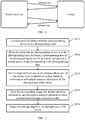
- a mobile terminal in FIG. 1 can be a mobile phone, a tablet computer, etc., and can include a photographing device.
- the mobile terminal can further include multiple groups of infrared emitters and multiple groups of receiving sensors.
- the infrared emitter can emit infrared rays
- the receiving sensor can receive infrared rays from the infrared emitter and sense temperatures of the received infrared rays.
- the article in FIG. 1 can be a bicycle or a car.
- the photographing device of the mobile terminal can operate simultaneously with the infrared emitter and/or the receiving sensor.
- the mobile terminal can start multiple groups of infrared emitters to emit multiple infrared rays to the photographing area of the article, so as to determine surface structure information (also referred to as depth information) and surface material information of the damaged part of the article.
- the mobile terminal can input the photographed image (visual information), the surface structure information, and the surface material information into the predetermined damage evaluation model, so as to output the damage degree of the damaged part of the article.
- efficiency of detecting the damage degree of the article can be improved, and accuracy of the detected damage degree can also be improved.
- FIG. 2 is a flowchart illustrating an article damage evaluation method, according to an implementation of the present specification.
- the method can be performed by the mobile terminal in FIG. 1 .
- the method can include the following:
- Step S210 A mobile terminal detects whether a photographing device is in a photographing state.
- the mobile terminal is a mobile phone
- the photographing device here can be a camera built in the mobile phone.
- Step S220 When detecting that the photographing device is in the photographing state, determine a photographing area of the photographing device for an article, and acquire a photographed image corresponding to the photographing area.
- the previously described photographing area can be determined based on a field of view as displayed by a viewfinder of the photographing device after successfully focusing the article. It can be understood that, when the user uses the mobile terminal to photograph a damaged part of the article, the previously described field of view can cover the damaged part of the article, so that the determined photographing area can cover the damaged part of the article.
- the photographed image corresponding to the photographing area is a photo obtained by photographing the damaged part of the article.
- Step S230 Emit multiple infrared rays to the photographing area of the article, so as to determine surface structure information and surface material information of the damaged part of the article.
- the process of determining the surface structure information can be as follows: The mobile terminal uses multiple groups of infrared emitters to emit multiple infrared rays to the photographing area of the article, and records an emitting time and an emitting speed of each infrared ray. Then, the mobile terminal uses multiple groups of receiving sensors to receive multiple infrared rays that are returned by the article after receiving the multiple infrared rays, and records a receiving time of each returned infrared ray. Finally, multiple different distances between the mobile terminal and the damaged part can be determined based on the recorded multiple emitting times, multiple emitting speeds, and multiple receiving times. Based on the multiple different distances, a three-dimensional structure of the damaged part can be obtained, i.e., the surface structure information of the damaged part of the article can be determined.
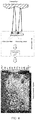
- the mobile terminal can determine a surface undulation diagram of the damaged part. It can be understood that, whether there is deformation on the surface of the damaged part can be determined based on the determined surface undulation diagram.
- the process of determining the surface undulation diagram can be shown in FIG. 3 .
- the mobile terminal can further include a conversion unit.
- the conversion unit is configured to convert the received infrared signal into a digital signal so that the computer can process the signal.
- the finally determined surface undulation diagram can be three-dimensional, thus facilitating the determining of the damage degree of the damaged part.
- the surface structure information can be further corrected with reference to an image acquired by the depth of field camera or the binocular camera.
- accuracy of determining the damage degree of the damaged part can be improved.
- the process of determining the surface structure information is described previously.
- the process of determining the surface material information can be as follows: The mobile terminal uses multiple groups of infrared emitters to emit multiple infrared rays to the photographing area of the article. Then, the mobile terminal uses multiple groups of receiving sensors to receive multiple infrared rays that are returned by the article after receiving the multiple infrared rays, and records a receiving temperature of each returned infrared ray. Finally, the surface material information of the damaged part can be determined based on the recorded multiple receiving temperatures. The principle of the determination process is that the temperatures of the infrared rays returned by different materials are different.
- the mobile terminal can determine a surface material diagram of the damaged part. It can be understood that, it can be determined, based on the determined surface material diagram, whether there is paint peeling, dust coverage, metal layer exposure, etc. on the damaged part.
- the process of determining the surface material diagram can be shown in FIG. 4 .
- the mobile terminal can further include a conversion unit (same as previous description).
- the process of determining the surface structure information and the process of determining the surface material information can be performed separately or simultaneously, which is not limited in the present specification.
- Step S240 Input the photographed image, the surface structure information, and the surface material information into a predetermined damage evaluation model.
- Step S250 Output the damage degree of the damaged part of the article.
- the damage evaluation model here can be obtained based on photographed images, surface structure information, surface material information, and deep learning training algorithms of damaged parts of multiple sample articles.
- Multiple sample articles can be collected in advance, and are labeled with sample labels (e.g., minor damage, moderate damage, severe damage, etc.).
- sample labels e.g., minor damage, moderate damage, severe damage, etc.
- the damaged part of the sample article is photographed, and the surface structure information and the surface material information of the damaged part are obtained (the obtaining process is the same as previous description).
- a deep neural network is trained based on the sample labels of the sample articles, the photographed images, the surface structure information, and the surface material information of the damaged parts, to obtain a trained damage evaluation model.
- Model training based on sample data belongs to the conventional technology, and is omitted here for simplicity.
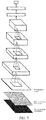
- the damage evaluation model obtained through training can include one or more convolutional layers, one or more pooling layers, and one or more fully connected layers.
- the photographed image, the surface structure information, and the surface material information are input into the damage evaluation model obtained through training based on the convolutional neural network, to identify the damage degree of the damaged part, as shown in FIG. 5 .
- the damage degree that's finally output in the present implementation can be minor damage (including slight deformation, paint peeling, etc.), moderate damage, severe damage, etc.
- the damage degree can also be other information used to indicate the damage degree, which is not limited in the present specification.
- the mobile terminal automatically performs damage evaluation on the damaged part, thus significantly reducing experience needs of damage evaluation, providing a fair and objective evaluation result, increasing difficulty of cheating and falsification, and enabling the user to personally provide an accurate and reliable evaluation result so that costs for on-site manual inspection of the insurance company are reduced.
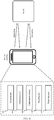
- the apparatus includes the following: a detection unit 601, configured to detect whether a photographing device is in a photographing state; a determining unit 602, configured to: when the detection unit 601 detects that the photographing device is in the photographing state, determine a photographing area of the photographing device for an article, where the photographing area covers a damaged part of the article, and acquire a photographed image corresponding to the photographing area; a communications unit 603, configured to emit multiple infrared rays to the photographing area, determined by the determining unit 602, of the article, so as to determine surface structure information and surface material information of the damaged part of the article, where the communications unit 603 can include multiple groups of infrared emitters and multiple groups of receiving sensors corresponding to the multiple groups of infrared emitters; an inputting unit 604, configured to input the photographed image, the surface structure information, and the surface material information into a predetermined
- the communications unit 603 can be configured to: emit multiple infrared rays to the photographing area of the article, and record an emitting time and an emitting speed; receive multiple infrared rays returned by the article after receiving the multiple infrared rays, and record a receiving time and a receiving temperature; determine the surface structure information of the damaged part of the article, based on the emitting time, the emitting speed, and the receiving time; and determine the surface material information of the damaged part of the article, based on the receiving temperature.
- the apparatus can further include the following: an acquisition unit 606, configured to acquire a target image of the article, by using a depth of field camera or a binocular camera; and a correction unit 607, configured to correct the surface structure information based on the target image acquired by the acquisition unit 606, to obtain the corrected surface structure information.
- an acquisition unit 606 configured to acquire a target image of the article, by using a depth of field camera or a binocular camera
- a correction unit 607 configured to correct the surface structure information based on the target image acquired by the acquisition unit 606, to obtain the corrected surface structure information.
- the inputting unit 604 can be configured to: input the photographed image, the corrected surface structure information, and the surface material information into the predetermined damage evaluation model.
- the damage evaluation model can be obtained based on photographed images, surface structure information, surface material information, and deep neural networks of damaged parts of multiple sample articles.
- a detection unit 601 detects whether a photographing device is in a photographing state.
- a determining unit 602 determines a photographing area of the photographing device for an article, and acquires a photographed image corresponding to the photographing area.
- a communications unit 603 emits multiple infrared rays to the photographing area of the article, so as to determine surface structure information and surface material information of the damaged part of the article.
- An inputting unit 604 inputs the photographed image, the surface structure information, and the surface material information into a predetermined damage evaluation model.
- An outputting unit 605 outputs a damage degree of the damaged part of the article. As such, the damage degree of the article can be automatically evaluated.
- the article damage evaluation apparatus provided in the implementations of the present specification can be a module or unit of the mobile terminal in FIG. 1 .
Landscapes
- Engineering & Computer Science (AREA)
- Physics & Mathematics (AREA)
- Theoretical Computer Science (AREA)
- General Physics & Mathematics (AREA)
- General Health & Medical Sciences (AREA)
- Health & Medical Sciences (AREA)
- Evolutionary Computation (AREA)
- Computer Vision & Pattern Recognition (AREA)
- Business, Economics & Management (AREA)
- Life Sciences & Earth Sciences (AREA)
- Artificial Intelligence (AREA)
- Software Systems (AREA)
- Computing Systems (AREA)
- Multimedia (AREA)
- Data Mining & Analysis (AREA)
- Pathology (AREA)
- General Engineering & Computer Science (AREA)
- Immunology (AREA)
- Analytical Chemistry (AREA)
- Biochemistry (AREA)
- Chemical & Material Sciences (AREA)
- Quality & Reliability (AREA)
- Databases & Information Systems (AREA)
- Human Resources & Organizations (AREA)
- Medical Informatics (AREA)
- Biomedical Technology (AREA)
- Biophysics (AREA)
- Mathematical Physics (AREA)
- Molecular Biology (AREA)
- Computational Linguistics (AREA)
- Economics (AREA)
- General Business, Economics & Management (AREA)
- Marketing (AREA)
- Strategic Management (AREA)
- Signal Processing (AREA)
- Tourism & Hospitality (AREA)
- Entrepreneurship & Innovation (AREA)
- Operations Research (AREA)
- Spectroscopy & Molecular Physics (AREA)
- Accounting & Taxation (AREA)
Abstract
Description
- One or more implementations of the present specification relate to the field of computer technologies, and in particular, to article damage evaluation methods and apparatuses.
- In the insurance industry, when a user claims for compensation for damage to an article, an insurance company needs to evaluate a degree of damage to the article, so as to determine a list of items that need to be repaired and an amount of compensation. At present, there are mainly two evaluation methods. A first method is that an adjuster from the insurance company or a third-party evaluation institution conducts on-site evaluation of the damaged article. A second method is that the user photographs the damaged article under the guidance of personnel from the insurance company, and transmits photos to the insurance company over a network, and then a damage evaluator conducts remote damage evaluation based on the photos.
- Therefore, there is a need to provide a more efficient article damage evaluation solution.
- One or more implementations of the present specification provide article damage evaluation methods and apparatuses, so as to automatically evaluate a damage degree of an article.
- According to a first aspect, an article damage evaluation method is provided, including the following: detecting, by a mobile terminal, whether a photographing device is in a photographing state; when detecting that the photographing device is in the photographing state, determining a photographing area of the photographing device for an article, where the photographing area covers a damaged part of the article, and acquiring a photographed image corresponding to the photographing area; emitting multiple infrared rays to the photographing area of the article, so as to determine surface structure information and surface material information of the damaged part of the article; inputting the photographed image, the surface structure information, and the surface material information into a predetermined damage evaluation model; and outputting a damage degree of the damaged part of the article.
- According to a second aspect, an article damage evaluation apparatus is provided, including the following: a detection unit, configured to detect whether a photographing device is in a photographing state; a determining unit, configured to: when the detection unit detects that the photographing device is in the photographing state, determine a photographing area of the photographing device for an article, where the photographing area covers a damaged part of the article, and acquire a photographed image corresponding to the photographing area; a communications unit, configured to emit multiple infrared rays to the photographing area, determined by the determining unit, of the article, so as to determine surface structure information and surface material information of the damaged part of the article; an inputting unit, configured to input the photographed image, the surface structure information, and the surface material information into a predetermined damage evaluation model; and an outputting unit, configured to output a damage degree of the damaged part of the article.
- In the article damage evaluation methods and apparatuses provided in one or more implementations of the present specification, when detecting that a photographing device is in a photographing state, a mobile terminal determines a photographing area of the photographing device for an article, and acquires a photographed image corresponding to the photographing area; emits multiple infrared rays to the photographing area of the article, so as to determine surface structure information and surface material information of the damaged part of the article; inputs the photographed image, the surface structure information, and the surface material information into a predetermined damage evaluation model; and outputs a damage degree of the damaged part of the article. As such, the damage degree of the article can be automatically evaluated.
- To describe the technical solutions in the implementations of the present specification more clearly, the following briefly describes the accompanying drawings needed for describing the implementations. Clearly, the accompanying drawings in the following description show merely some implementations of the present specification, and a person of ordinary skill in the art can still derive other drawings from these accompanying drawings without creative efforts.
-
FIG. 1 is a schematic diagram illustrating an application scenario of an article damage evaluation method, according to an implementation of the present specification; -
FIG. 2 is a flowchart illustrating an article damage evaluation method, according to an implementation of the present specification; -
FIG. 3 is a schematic diagram illustrating a process of determining a surface undulation diagram, according to the present specification; -
FIG. 4 is a schematic diagram illustrating a process of determining a surface material diagram, according to the present specification; -
FIG. 5 is a schematic diagram illustrating an article damage evaluation process, according to the present specification; and -
FIG. 6 is a schematic diagram illustrating an article damage evaluation apparatus, according to an implementation of the present specification. - The following describes the solutions provided in the present specification with reference to the accompanying drawings.
- An article damage evaluation method provided in an implementation of the present specification can be applied to a scenario shown in
FIG. 1 . For example, a mobile terminal inFIG. 1 can be a mobile phone, a tablet computer, etc., and can include a photographing device. In addition, the mobile terminal can further include multiple groups of infrared emitters and multiple groups of receiving sensors. The infrared emitter can emit infrared rays, the receiving sensor can receive infrared rays from the infrared emitter and sense temperatures of the received infrared rays. For example, the article inFIG. 1 can be a bicycle or a car. - It is worthwhile to note that, in
FIG. 1 , the photographing device of the mobile terminal can operate simultaneously with the infrared emitter and/or the receiving sensor. When photographing the damaged part of the article, the mobile terminal can start multiple groups of infrared emitters to emit multiple infrared rays to the photographing area of the article, so as to determine surface structure information (also referred to as depth information) and surface material information of the damaged part of the article. Then, the mobile terminal can input the photographed image (visual information), the surface structure information, and the surface material information into the predetermined damage evaluation model, so as to output the damage degree of the damaged part of the article. Thus, efficiency of detecting the damage degree of the article can be improved, and accuracy of the detected damage degree can also be improved. -
FIG. 2 is a flowchart illustrating an article damage evaluation method, according to an implementation of the present specification. The method can be performed by the mobile terminal inFIG. 1 . As shown inFIG. 2 , the method can include the following: - Step S210: A mobile terminal detects whether a photographing device is in a photographing state.
- For example, the mobile terminal is a mobile phone, and the photographing device here can be a camera built in the mobile phone.
- Step S220: When detecting that the photographing device is in the photographing state, determine a photographing area of the photographing device for an article, and acquire a photographed image corresponding to the photographing area.
- In some implementations, the previously described photographing area can be determined based on a field of view as displayed by a viewfinder of the photographing device after successfully focusing the article. It can be understood that, when the user uses the mobile terminal to photograph a damaged part of the article, the previously described field of view can cover the damaged part of the article, so that the determined photographing area can cover the damaged part of the article.
- It can be understood that, when the photographing area covers the damaged part of the article, the photographed image corresponding to the photographing area is a photo obtained by photographing the damaged part of the article.
- Step S230: Emit multiple infrared rays to the photographing area of the article, so as to determine surface structure information and surface material information of the damaged part of the article.
- In some implementations, the process of determining the surface structure information can be as follows: The mobile terminal uses multiple groups of infrared emitters to emit multiple infrared rays to the photographing area of the article, and records an emitting time and an emitting speed of each infrared ray. Then, the mobile terminal uses multiple groups of receiving sensors to receive multiple infrared rays that are returned by the article after receiving the multiple infrared rays, and records a receiving time of each returned infrared ray. Finally, multiple different distances between the mobile terminal and the damaged part can be determined based on the recorded multiple emitting times, multiple emitting speeds, and multiple receiving times. Based on the multiple different distances, a three-dimensional structure of the damaged part can be obtained, i.e., the surface structure information of the damaged part of the article can be determined.
- After determining the surface structure information, the mobile terminal can determine a surface undulation diagram of the damaged part. It can be understood that, whether there is deformation on the surface of the damaged part can be determined based on the determined surface undulation diagram.
- For example, the process of determining the surface undulation diagram can be shown in
FIG. 3 . InFIG. 3 , the mobile terminal can further include a conversion unit. The conversion unit is configured to convert the received infrared signal into a digital signal so that the computer can process the signal. As can be seen fromFIG. 3 , the finally determined surface undulation diagram can be three-dimensional, thus facilitating the determining of the damage degree of the damaged part. - Certainly, in practice, when the mobile terminal further includes a depth of field camera or a binocular camera, the surface structure information can be further corrected with reference to an image acquired by the depth of field camera or the binocular camera. Thus, accuracy of determining the damage degree of the damaged part can be improved.
- The process of determining the surface structure information is described previously. The process of determining the surface material information can be as follows: The mobile terminal uses multiple groups of infrared emitters to emit multiple infrared rays to the photographing area of the article. Then, the mobile terminal uses multiple groups of receiving sensors to receive multiple infrared rays that are returned by the article after receiving the multiple infrared rays, and records a receiving temperature of each returned infrared ray. Finally, the surface material information of the damaged part can be determined based on the recorded multiple receiving temperatures. The principle of the determination process is that the temperatures of the infrared rays returned by different materials are different.
- After determining the surface material information, the mobile terminal can determine a surface material diagram of the damaged part. It can be understood that, it can be determined, based on the determined surface material diagram, whether there is paint peeling, dust coverage, metal layer exposure, etc. on the damaged part.
- For example, the process of determining the surface material diagram can be shown in
FIG. 4 . InFIG. 4 , the mobile terminal can further include a conversion unit (same as previous description). - It can be understood that, the process of determining the surface structure information and the process of determining the surface material information can be performed separately or simultaneously, which is not limited in the present specification.
- Step S240: Input the photographed image, the surface structure information, and the surface material information into a predetermined damage evaluation model.
- Step S250: Output the damage degree of the damaged part of the article.
- The damage evaluation model here can be obtained based on photographed images, surface structure information, surface material information, and deep learning training algorithms of damaged parts of multiple sample articles. Multiple sample articles can be collected in advance, and are labeled with sample labels (e.g., minor damage, moderate damage, severe damage, etc.). Then, the damaged part of the sample article is photographed, and the surface structure information and the surface material information of the damaged part are obtained (the obtaining process is the same as previous description). Finally, a deep neural network is trained based on the sample labels of the sample articles, the photographed images, the surface structure information, and the surface material information of the damaged parts, to obtain a trained damage evaluation model. Model training based on sample data belongs to the conventional technology, and is omitted here for simplicity.
- It is worthwhile to note that, when the deep neural network is a convolutional neural network, the damage evaluation model obtained through training can include one or more convolutional layers, one or more pooling layers, and one or more fully connected layers.
- For example, the photographed image, the surface structure information, and the surface material information are input into the damage evaluation model obtained through training based on the convolutional neural network, to identify the damage degree of the damaged part, as shown in
FIG. 5 . - For example, the damage degree that's finally output in the present implementation can be minor damage (including slight deformation, paint peeling, etc.), moderate damage, severe damage, etc. Certainly, in practice, the damage degree can also be other information used to indicate the damage degree, which is not limited in the present specification.
- In conclusion, the solutions provided in the implementations of the present specification have the following advantages:
- (1) The accuracy of identifying deformation can be improved with reference to the surface structure information and the photographed image of the damaged part of the article.
- (2) Visual interfering factors such as light reflection, inverted image, dust stain, etc. can be corrected by using the surface material information and the surface structure information of the damaged part, so as to prevent the deep neural network from misidentifying the visual interfering factors as damage.
- (3) The damage degree is determined more accurately, particularly for the damage such as slight deformation or paint peeling, so as to increase the accuracy to an extent that cannot be achieved by using visual information only.
- In a word, in the present solution, when damage evaluation is performed on the damaged part of the article, both the image of the damaged part and the surface structure information and surface material information of the damaged part are considered, thus providing more complete damage evaluation capability. In addition, in the present solution, the mobile terminal automatically performs damage evaluation on the damaged part, thus significantly reducing experience needs of damage evaluation, providing a fair and objective evaluation result, increasing difficulty of cheating and falsification, and enabling the user to personally provide an accurate and reliable evaluation result so that costs for on-site manual inspection of the insurance company are reduced.
- Corresponding to the previously described article damage evaluation method, an implementation of the present specification further provides an article damage evaluation apparatus. As shown in
FIG. 6 , the apparatus includes the following: adetection unit 601, configured to detect whether a photographing device is in a photographing state; a determiningunit 602, configured to: when thedetection unit 601 detects that the photographing device is in the photographing state, determine a photographing area of the photographing device for an article, where the photographing area covers a damaged part of the article, and acquire a photographed image corresponding to the photographing area; acommunications unit 603, configured to emit multiple infrared rays to the photographing area, determined by the determiningunit 602, of the article, so as to determine surface structure information and surface material information of the damaged part of the article, where thecommunications unit 603 can include multiple groups of infrared emitters and multiple groups of receiving sensors corresponding to the multiple groups of infrared emitters; aninputting unit 604, configured to input the photographed image, the surface structure information, and the surface material information into a predetermined damage evaluation model; and anoutputting unit 605, configured to output a damage degree of the damaged part of the article. - Optionally, the
communications unit 603 can be configured to: emit multiple infrared rays to the photographing area of the article, and record an emitting time and an emitting speed; receive multiple infrared rays returned by the article after receiving the multiple infrared rays, and record a receiving time and a receiving temperature; determine the surface structure information of the damaged part of the article, based on the emitting time, the emitting speed, and the receiving time; and determine the surface material information of the damaged part of the article, based on the receiving temperature. - Optionally, the apparatus can further include the following: an acquisition unit 606, configured to acquire a target image of the article, by using a depth of field camera or a binocular camera; and a correction unit 607, configured to correct the surface structure information based on the target image acquired by the acquisition unit 606, to obtain the corrected surface structure information.
- The inputting
unit 604 can be configured to: input the photographed image, the corrected surface structure information, and the surface material information into the predetermined damage evaluation model. - The damage evaluation model can be obtained based on photographed images, surface structure information, surface material information, and deep neural networks of damaged parts of multiple sample articles.
- The functions of the functional modules of the apparatus in the previous implementation of the present specification can be implemented by using the steps of the previous method implementation. Therefore, a specific working process of the apparatus provided in an implementation of the present specification is omitted here for simplicity.
- In an article damage evaluation apparatus provided in an implementation of the present specification, a
detection unit 601 detects whether a photographing device is in a photographing state. When detecting that the photographing device is in the photographing state, a determiningunit 602 determines a photographing area of the photographing device for an article, and acquires a photographed image corresponding to the photographing area. Acommunications unit 603 emits multiple infrared rays to the photographing area of the article, so as to determine surface structure information and surface material information of the damaged part of the article. Aninputting unit 604 inputs the photographed image, the surface structure information, and the surface material information into a predetermined damage evaluation model. Anoutputting unit 605 outputs a damage degree of the damaged part of the article. As such, the damage degree of the article can be automatically evaluated. - The article damage evaluation apparatus provided in the implementations of the present specification can be a module or unit of the mobile terminal in
FIG. 1 . - A person skilled in the art should be aware that in the previously described one or more examples, functions described in the present specification can be implemented by hardware, software, firmware, or any combination thereof. When being implemented by using software, these functions can be stored in a computer-readable medium or transmitted as one or more instructions or code in the computer-readable medium.
- The objectives, technical solutions, and beneficial effects of the present specification are further described in detail in the previously described specific implementations. It should be understood that the previous descriptions are merely specific implementations of the present specification, but are not intended to limit the protection scope of the present specification. Any modification, equivalent replacement, or improvement made based on the technical solutions of the present specification shall fall within the protection scope of the present specification.
Claims (10)
- An article damage evaluation method, comprising:detecting, by a mobile terminal, whether a photographing device is in a photographing state;when detecting that the photographing device is in the photographing state, determining a photographing area of the photographing device for an article, wherein the photographing area covers a damaged part of the article, and acquiring a photographed image corresponding to the photographing area;emitting multiple infrared rays to the photographing area of the article, so as to determine surface structure information and surface material information of the damaged part of the article;inputting the photographed image, the surface structure information, and the surface material information into a predetermined damage evaluation model; andoutputting a damage degree of the damaged part of the article.
- The method according to claim 1, wherein the emitting multiple infrared rays to the photographing area of the article, so as to determine surface structure information and surface material information of the damaged part of the article comprises:emitting multiple infrared rays to the photographing area of the article, and recording an emitting time and an emitting speed;receiving multiple infrared rays returned by the article after receiving the multiple infrared rays, and recording a receiving time and a receiving temperature;determining the surface structure information of the damaged part of the article, based on the emitting time, the emitting speed, and the receiving time; anddetermining the surface material information of the damaged part of the article, based on the receiving temperature.
- The method according to claim 2, wherein the method further comprises:acquiring a target image of the article, by using a depth of field camera or a binocular camera; andcorrecting the surface structure information based on the target image, to obtain the corrected surface structure information; andthe inputting the photographed image, the surface structure information, and the surface material information into a predetermined damage evaluation model comprises:
inputting the photographed image, the corrected surface structure information, and the surface material information into the predetermined damage evaluation model. - The method according to claim 2, wherein the mobile terminal emits the multiple infrared rays by using multiple groups of infrared emitters; the mobile terminal receives the returned multiple infrared rays by using multiple groups of receiving sensors corresponding to the multiple groups of infrared emitters.
- The method according to any one of claims 1 to 4, wherein the damage evaluation model is obtained based on photographed images, surface structure information, surface material information, and deep neural networks of damaged parts of multiple sample articles.
- An article damage evaluation apparatus, comprising:a detection unit, configured to detect whether a photographing device is in a photographing state;a determining unit, configured to: when the detection unit detects that the photographing device is in the photographing state, determine a photographing area of the photographing device for an article, wherein the photographing area covers a damaged part of the article, and acquire a photographed image corresponding to the photographing area;a communications unit, configured to emit multiple infrared rays to the photographing area, determined by the determining unit, of the article, so as to determine surface structure information and surface material information of the damaged part of the article;an inputting unit, configured to input the photographed image, the surface structure information, and the surface material information into a predetermined damage evaluation model; andan outputting unit, configured to output a damage degree of the damaged part of the article.
- The apparatus according to claim 6, wherein the communications unit is configured to:emit multiple infrared rays to the photographing area of the article, and record an emitting time and an emitting speed;receive multiple infrared rays returned by the article after receiving the multiple infrared rays, and record a receiving time and a receiving temperature;determine the surface structure information of the damaged part of the article, based on the emitting time, the emitting speed, and the receiving time; anddetermine the surface material information of the damaged part of the article, based on the receiving temperature.
- The apparatus according to claim 7, further comprising:an acquisition unit, configured to acquire a target image of the article, by using a depth of field camera or a binocular camera; anda correction unit, configured to correct the surface structure information based on the target image acquired by the acquisition unit, to obtain the corrected surface structure information; andthe inputting unit is configured to:
input the photographed image, the corrected surface structure information, and the surface material information into the predetermined damage evaluation model. - The apparatus according to claim 7, wherein the communications unit comprises multiple groups of infrared emitters and multiple groups of receiving sensors corresponding to the multiple groups of infrared emitters.
- The apparatus according to any one of claims 6 to 9, wherein the damage evaluation model is obtained based on photographed images, surface structure information, surface material information, and deep neural networks of damaged parts of multiple sample articles.
Applications Claiming Priority (2)
| Application Number | Priority Date | Filing Date | Title |
|---|---|---|---|
| CN201810220310.2A CN108550080A (en) | 2018-03-16 | 2018-03-16 | Article damage identification method and device |
| PCT/CN2018/117861 WO2019174306A1 (en) | 2018-03-16 | 2018-11-28 | Item damage assessment method and device |
Publications (2)
| Publication Number | Publication Date |
|---|---|
| EP3716204A1 true EP3716204A1 (en) | 2020-09-30 |
| EP3716204A4 EP3716204A4 (en) | 2020-12-30 |
Family
ID=63516626
Family Applications (1)
| Application Number | Title | Priority Date | Filing Date |
|---|---|---|---|
| EP18909705.8A Ceased EP3716204A4 (en) | 2018-03-16 | 2018-11-28 | METHOD AND DEVICE FOR EVALUATING ITEM DAMAGE |
Country Status (6)
| Country | Link |
|---|---|
| US (1) | US11300522B2 (en) |
| EP (1) | EP3716204A4 (en) |
| CN (1) | CN108550080A (en) |
| SG (1) | SG11202005713XA (en) |
| TW (1) | TWI683260B (en) |
| WO (1) | WO2019174306A1 (en) |
Families Citing this family (10)
| Publication number | Priority date | Publication date | Assignee | Title |
|---|---|---|---|---|
| CN106803205A (en) * | 2016-12-27 | 2017-06-06 | 北京量子保科技有限公司 | A kind of system and method for insuring from kinetonucleus compensation |
| CN108550080A (en) | 2018-03-16 | 2018-09-18 | 阿里巴巴集团控股有限公司 | Article damage identification method and device |
| CN109615649A (en) * | 2018-10-31 | 2019-04-12 | 阿里巴巴集团控股有限公司 | An image labeling method, device and system |
| CN109900702A (en) * | 2018-12-03 | 2019-06-18 | 阿里巴巴集团控股有限公司 | Processing method, device, equipment, server and the system of vehicle damage detection |
| CN110045382A (en) * | 2018-12-03 | 2019-07-23 | 阿里巴巴集团控股有限公司 | Processing method, device, equipment, server and the system of vehicle damage detection |
| CN111586225B (en) * | 2020-05-19 | 2021-08-06 | 杨泽鹏 | Image acquisition auxiliary system |
| CN113379745B (en) * | 2021-08-13 | 2021-11-30 | 深圳市信润富联数字科技有限公司 | Product defect identification method and device, electronic equipment and storage medium |
| CN115184378B (en) * | 2022-09-15 | 2024-03-29 | 北京思莫特科技有限公司 | Concrete structure disease detection system and method based on mobile equipment |
| CN118663567A (en) * | 2024-06-19 | 2024-09-20 | 山东天同食品有限公司 | Raw material screening device for fruit can processing |
| CN119888506B (en) * | 2025-03-26 | 2025-06-17 | 悦读天下(北京)国际教育科技有限公司 | Book cover offset intelligent detection method and system based on image recognition |
Family Cites Families (29)
| Publication number | Priority date | Publication date | Assignee | Title |
|---|---|---|---|---|
| US6495833B1 (en) * | 2000-01-20 | 2002-12-17 | Research Foundation Of Cuny | Sub-surface imaging under paints and coatings using early light spectroscopy |
| DE10305861A1 (en) * | 2003-02-13 | 2004-08-26 | Adam Opel Ag | Motor vehicle device for spatial measurement of a scene inside or outside the vehicle, combines a LIDAR system with an image sensor system to obtain optimum 3D spatial image data |
| US7451657B2 (en) * | 2004-01-16 | 2008-11-18 | Jentek Sensors, Inc. | Material condition monitoring with multiple sensing modes |
| EP2281255A4 (en) * | 2008-04-17 | 2013-02-20 | Travelers Indemnity Co | A method of and system for determining and processing object structure condition information |
| CN101995395B (en) * | 2009-08-14 | 2013-07-31 | 上海镭立激光科技有限公司 | Method for online detecting material by laser induction multiple spectrum united fingerprint network |
| FI124299B (en) * | 2009-10-08 | 2014-06-13 | Focalspec Oy | MEASURING INSTRUMENT AND METHOD FOR MEASURING THE PROPERTIES OF THE SUBJECT AND SURFACE |
| US9424606B2 (en) * | 2011-04-28 | 2016-08-23 | Allstate Insurance Company | Enhanced claims settlement |
| US20140201022A1 (en) * | 2013-01-16 | 2014-07-17 | Andre Balzer | Vehicle damage processing and information system |
| CN103310223A (en) * | 2013-03-13 | 2013-09-18 | 四川天翼网络服务有限公司 | Vehicle loss assessment system based on image recognition and method thereof |
| KR102136401B1 (en) * | 2013-10-21 | 2020-07-21 | 한국전자통신연구원 | Multi-wave image lidar sensor apparatus and signal processing method thereof |
| CN203643383U (en) * | 2013-12-17 | 2014-06-11 | 上海神洲阳光特种钢管有限公司 | Infrared flaw detection device |
| DE102014212682A1 (en) * | 2014-07-01 | 2016-01-07 | Trumpf Werkzeugmaschinen Gmbh + Co. Kg | Method and device for determining a type of material and / or a surface finish of a workpiece |
| US10535103B1 (en) * | 2014-09-22 | 2020-01-14 | State Farm Mutual Automobile Insurance Company | Systems and methods of utilizing unmanned vehicles to detect insurance claim buildup |
| US9129355B1 (en) * | 2014-10-09 | 2015-09-08 | State Farm Mutual Automobile Insurance Company | Method and system for assessing damage to infrastructure |
| US10523855B2 (en) * | 2015-09-24 | 2019-12-31 | Intel Corporation | Infrared and visible light dual sensor imaging system |
| US20170147990A1 (en) * | 2015-11-23 | 2017-05-25 | CSI Holdings I LLC | Vehicle transactions using objective vehicle data |
| US10354386B1 (en) * | 2016-01-27 | 2019-07-16 | United Services Automobile Association (Usaa) | Remote sensing of structure damage |
| US11144889B2 (en) * | 2016-04-06 | 2021-10-12 | American International Group, Inc. | Automatic assessment of damage and repair costs in vehicles |
| US10692050B2 (en) * | 2016-04-06 | 2020-06-23 | American International Group, Inc. | Automatic assessment of damage and repair costs in vehicles |
| CN105915853A (en) * | 2016-05-27 | 2016-08-31 | 大连楼兰科技股份有限公司 | Remote unmanned damage assessment method and system based on infrared perception |
| CN107392218B (en) * | 2017-04-11 | 2020-08-04 | 创新先进技术有限公司 | An image-based vehicle damage assessment method, device and electronic device |
| CN107358596B (en) * | 2017-04-11 | 2020-09-18 | 阿里巴巴集团控股有限公司 | An image-based vehicle damage assessment method, device, electronic device and system |
| CN107622448A (en) * | 2017-08-28 | 2018-01-23 | 武汉六点整北斗科技有限公司 | The insurance verification method and Related product of a kind of traffic accident |
| US11087292B2 (en) * | 2017-09-01 | 2021-08-10 | Allstate Insurance Company | Analyzing images and videos of damaged vehicles to determine damaged vehicle parts and vehicle asymmetries |
| KR101916347B1 (en) * | 2017-10-13 | 2018-11-08 | 주식회사 수아랩 | Deep learning based image comparison device, method and computer program stored in computer readable medium |
| JP7073785B2 (en) * | 2018-03-05 | 2022-05-24 | オムロン株式会社 | Image inspection equipment, image inspection method and image inspection program |
| CN108550080A (en) * | 2018-03-16 | 2018-09-18 | 阿里巴巴集团控股有限公司 | Article damage identification method and device |
| US10592934B2 (en) * | 2018-03-30 | 2020-03-17 | The Travelers Indemnity Company | Systems and methods for automated multi-object damage analysis |
| CN110570316A (en) * | 2018-08-31 | 2019-12-13 | 阿里巴巴集团控股有限公司 | Method and device for training damage recognition model |
-
2018
- 2018-03-16 CN CN201810220310.2A patent/CN108550080A/en active Pending
- 2018-11-28 EP EP18909705.8A patent/EP3716204A4/en not_active Ceased
- 2018-11-28 SG SG11202005713XA patent/SG11202005713XA/en unknown
- 2018-11-28 WO PCT/CN2018/117861 patent/WO2019174306A1/en not_active Ceased
-
2019
- 2019-01-03 TW TW108100204A patent/TWI683260B/en not_active IP Right Cessation
-
2020
- 2020-05-29 US US16/888,598 patent/US11300522B2/en active Active
Also Published As
| Publication number | Publication date |
|---|---|
| US11300522B2 (en) | 2022-04-12 |
| TWI683260B (en) | 2020-01-21 |
| CN108550080A (en) | 2018-09-18 |
| SG11202005713XA (en) | 2020-07-29 |
| EP3716204A4 (en) | 2020-12-30 |
| TW201941100A (en) | 2019-10-16 |
| WO2019174306A1 (en) | 2019-09-19 |
| US20200292464A1 (en) | 2020-09-17 |
Similar Documents
| Publication | Publication Date | Title |
|---|---|---|
| US11300522B2 (en) | Article damage evaluation | |
| EP1732314B1 (en) | Infrared camera with humidity sensor | |
| US20190095877A1 (en) | Image recognition system for rental vehicle damage detection and management | |
| US11080839B2 (en) | System and method for training a damage identification model | |
| CN111739250B (en) | Fire detection method and system combining image processing technology and infrared sensor | |
| Goncalves et al. | A visual front-end for simultaneous localization and mapping | |
| CN111426393B (en) | Temperature correction method, device and system | |
| CN104215179B (en) | The method that width of steel billet is dynamically measured using laser displacement sensor | |
| CN105844240A (en) | Method and device for detecting human faces in infrared temperature measurement system | |
| WO2020038138A1 (en) | Sample labeling method and device, and damage category identification method and device | |
| JP6807268B2 (en) | Image recognition engine linkage device and program | |
| WO2019196476A1 (en) | Laser sensor-based map generation | |
| CN112862757A (en) | Weight evaluation system based on computer vision technology and implementation method | |
| JP2016070676A (en) | Arithmetic apparatus, arithmetic method, and program | |
| CN110119731A (en) | The device and method of 3-D image processing | |
| TWI468658B (en) | Lens test device and method | |
| CN108764105B (en) | Assembly line workpiece identification method, server and terminal | |
| Su et al. | Dual-light inspection method for automatic pavement surveys | |
| CA3241753A1 (en) | Projector system and method for projecting images | |
| CN111754474A (en) | A method and device for visibility recognition based on image clarity | |
| TWM563010U (en) | Automatic labeling system | |
| Uchiyama et al. | Photogrammetric system using visible light communication | |
| CN110686602B (en) | Displacement testing system and displacement testing method | |
| KR102617048B1 (en) | Systme for recogniting label using infrared and cisible light camera and method thereof | |
| JP2018106439A (en) | Measurement support device |
Legal Events
| Date | Code | Title | Description |
|---|---|---|---|
| STAA | Information on the status of an ep patent application or granted ep patent |
Free format text: STATUS: THE INTERNATIONAL PUBLICATION HAS BEEN MADE |
|
| PUAI | Public reference made under article 153(3) epc to a published international application that has entered the european phase |
Free format text: ORIGINAL CODE: 0009012 |
|
| STAA | Information on the status of an ep patent application or granted ep patent |
Free format text: STATUS: REQUEST FOR EXAMINATION WAS MADE |
|
| 17P | Request for examination filed |
Effective date: 20200624 |
|
| AK | Designated contracting states |
Kind code of ref document: A1 Designated state(s): AL AT BE BG CH CY CZ DE DK EE ES FI FR GB GR HR HU IE IS IT LI LT LU LV MC MK MT NL NO PL PT RO RS SE SI SK SM TR |
|
| AX | Request for extension of the european patent |
Extension state: BA ME |
|
| RAP1 | Party data changed (applicant data changed or rights of an application transferred) |
Owner name: ADVANCED NEW TECHNOLOGIES CO., LTD. |
|
| RAP1 | Party data changed (applicant data changed or rights of an application transferred) |
Owner name: ALIBABA GROUP HOLDING LIMITED |
|
| A4 | Supplementary search report drawn up and despatched |
Effective date: 20201202 |
|
| RIC1 | Information provided on ipc code assigned before grant |
Ipc: G06T 7/00 20170101AFI20201126BHEP Ipc: G06Q 10/00 20120101ALI20201126BHEP Ipc: G01N 21/88 20060101ALI20201126BHEP Ipc: G06K 9/22 20060101ALI20201126BHEP Ipc: G06Q 40/08 20120101ALI20201126BHEP Ipc: G01N 21/3563 20140101ALI20201126BHEP Ipc: G06K 9/62 20060101ALI20201126BHEP |
|
| RAP1 | Party data changed (applicant data changed or rights of an application transferred) |
Owner name: ADVANCED NEW TECHNOLOGIES CO., LTD. |
|
| DAV | Request for validation of the european patent (deleted) | ||
| DAX | Request for extension of the european patent (deleted) | ||
| STAA | Information on the status of an ep patent application or granted ep patent |
Free format text: STATUS: EXAMINATION IS IN PROGRESS |
|
| 17Q | First examination report despatched |
Effective date: 20210701 |
|
| REG | Reference to a national code |
Ref country code: DE Ref legal event code: R003 |
|
| STAA | Information on the status of an ep patent application or granted ep patent |
Free format text: STATUS: THE APPLICATION HAS BEEN REFUSED |
|
| 18R | Application refused |
Effective date: 20221229 |