EP3716183A1 - Monitoring system - Google Patents
Monitoring system Download PDFInfo
- Publication number
- EP3716183A1 EP3716183A1 EP20150998.1A EP20150998A EP3716183A1 EP 3716183 A1 EP3716183 A1 EP 3716183A1 EP 20150998 A EP20150998 A EP 20150998A EP 3716183 A1 EP3716183 A1 EP 3716183A1
- Authority
- EP
- European Patent Office
- Prior art keywords
- information
- abnormality
- processing device
- information processing
- server
- Prior art date
- Legal status (The legal status is an assumption and is not a legal conclusion. Google has not performed a legal analysis and makes no representation as to the accuracy of the status listed.)
- Withdrawn
Links
Images


Classifications
-
- G—PHYSICS
- G06—COMPUTING OR CALCULATING; COUNTING
- G06Q—INFORMATION AND COMMUNICATION TECHNOLOGY [ICT] SPECIALLY ADAPTED FOR ADMINISTRATIVE, COMMERCIAL, FINANCIAL, MANAGERIAL OR SUPERVISORY PURPOSES; SYSTEMS OR METHODS SPECIALLY ADAPTED FOR ADMINISTRATIVE, COMMERCIAL, FINANCIAL, MANAGERIAL OR SUPERVISORY PURPOSES, NOT OTHERWISE PROVIDED FOR
- G06Q20/00—Payment architectures, schemes or protocols
- G06Q20/08—Payment architectures
- G06Q20/20—Point-of-sale [POS] network systems
-
- H—ELECTRICITY
- H04—ELECTRIC COMMUNICATION TECHNIQUE
- H04L—TRANSMISSION OF DIGITAL INFORMATION, e.g. TELEGRAPHIC COMMUNICATION
- H04L43/00—Arrangements for monitoring or testing data switching networks
- H04L43/08—Monitoring or testing based on specific metrics, e.g. QoS, energy consumption or environmental parameters
- H04L43/0805—Monitoring or testing based on specific metrics, e.g. QoS, energy consumption or environmental parameters by checking availability
- H04L43/0817—Monitoring or testing based on specific metrics, e.g. QoS, energy consumption or environmental parameters by checking availability by checking functioning
-
- G—PHYSICS
- G07—CHECKING-DEVICES
- G07F—COIN-FREED OR LIKE APPARATUS
- G07F19/00—Complete banking systems; Coded card-freed arrangements adapted for dispensing or receiving monies or the like and posting such transactions to existing accounts, e.g. automatic teller machines
-
- G—PHYSICS
- G06—COMPUTING OR CALCULATING; COUNTING
- G06F—ELECTRIC DIGITAL DATA PROCESSING
- G06F11/00—Error detection; Error correction; Monitoring
- G06F11/30—Monitoring
- G06F11/32—Monitoring with visual or acoustical indication of the functioning of the machine
-
- G—PHYSICS
- G07—CHECKING-DEVICES
- G07G—REGISTERING THE RECEIPT OF CASH, VALUABLES, OR TOKENS
- G07G1/00—Cash registers
- G07G1/10—Cash registers mechanically operated
-
- G—PHYSICS
- G07—CHECKING-DEVICES
- G07G—REGISTERING THE RECEIPT OF CASH, VALUABLES, OR TOKENS
- G07G3/00—Alarm indicators, e.g. bells
-
- G—PHYSICS
- G08—SIGNALLING
- G08B—SIGNALLING SYSTEMS, e.g. PERSONAL CALLING SYSTEMS; ORDER TELEGRAPHS; ALARM SYSTEMS
- G08B5/00—Visible signalling systems, e.g. visible personal calling systems or remote indication of seats occupied
- G08B5/22—Visible signalling systems, e.g. visible personal calling systems or remote indication of seats occupied using electric transmission; using electromagnetic transmission
- G08B5/36—Visible signalling systems, e.g. visible personal calling systems or remote indication of seats occupied using electric transmission; using electromagnetic transmission using visible light sources
- G08B5/38—Visible signalling systems, e.g. visible personal calling systems or remote indication of seats occupied using electric transmission; using electromagnetic transmission using visible light sources using flashing light
-
- H—ELECTRICITY
- H04—ELECTRIC COMMUNICATION TECHNIQUE
- H04L—TRANSMISSION OF DIGITAL INFORMATION, e.g. TELEGRAPHIC COMMUNICATION
- H04L43/00—Arrangements for monitoring or testing data switching networks
- H04L43/06—Generation of reports
- H04L43/065—Generation of reports related to network devices
Definitions
- Embodiments described herein relate generally to a monitoring system.
- abnormality information related to the lifetime of each part of a point of sales (POS) terminal installed in a store or abnormal operation is managed by a server connected to the POS terminal.
- the POS terminal transmits the own abnormality information thereof to the server via a network. For this reason, when a maintenance person who maintains POS terminals visits a store, it is necessary to check the information displayed on the server installed in the backyard to check the abnormality information of each POS terminal. Therefore, it takes significant and inconvenient time for the maintenance person to check the abnormality information of each POS terminal.
- Embodiments provide a monitoring system in which the maintenance person can obtain operation information of an information processing device without having to spend time in a store.
- a monitoring system includes an information processing device and a server, in which the information processing device includes an information transmission unit that transmits information related to operation log information to the server when the operation log information of the information processing device is detected, and the server includes a reception unit that receives the operation log information transmitted by the information transmission unit, a first operation modulation unit that generates frequency information indicating an operation of the information processing device based on the operation log information received by the reception unit, and a lighting control unit that blinks a lighting light source provided in a store to illuminate the store based on the frequency information generated by the first operation modulation unit.
- the information processing device further comprises a display that displays information, a second modulation component that generates frequency information indicating the operation based on the operation log information, and a display control component that blinks and displays the display based on the frequency information generated by the second modulation component.
- the lighting control component causes the lighting light source to blink at a predetermined frequency not based on the frequency information indicating the operation when the operation log information is not received.
- the operation log information comprises a description of an abnormality of the information processing device or an identity of an abnormality of the information processing device.
- the operation log information comprises a date and time of an abnormality of the information processing device.
- the information processing device is a POS terminal.
- the system may further comprise a plurality of information processing devices.
- the information processing device and server are connected by a wireless network.
- the present invention further relates to a monitoring system, comprising: an information processing device; a server; and a camera.
- the information processing device further comprises a display that displays information.
- the information processing device further comprises a modulation component that generates frequency information indicating an operation based on operation log information related to the operation when the operation of the information processing device is detected.
- the information processing device further comprises a display control component that blinks and displays the display based on the frequency information generated by the modulation component.
- the camera captures modulation information of the display blinked and displayed by the display control component.
- the server comprises a lighting control component that blinks a lighting light source that is provided in a store to illuminate the store, based on the modulation information captured by the camera.
- the lighting control component blinks the lighting light source at a predetermined frequency not based on the frequency information indicating the operation when the camera is not capturing the modulation information.
- the camera is comprised in a smartphone.
- the operation log information comprises a description of an abnormality of the information processing device or an identity of an abnormality of the information processing device.
- the operation log information comprises a date and time of an abnormality of the information processing device.
- the information processing device is a POS terminal.
- the system may further comprise a plurality of information processing devices.
- the information processing device and server are connected by a wireless network.
- the present invention also relates to a monitoring method, comprising: detecting and transmitting information related to operation log information of an information processing device to a server when the operation log information of the information processing device; receiving by the server the operation log information transmitted; generating frequency information indicating an operation of the information processing device based on the operation log information received; and blinking a lighting light source provided in a store to illuminate the store based on the frequency information generated.
- the method may further comprise: displaying information; generating frequency information indicating the operation based on the operation log information; and blinking and displaying the displayed information based on the frequency information generated.
- the method may further comprise: causing the lighting light source to blink at a predetermined frequency not based on the frequency information indicating the operation when the operation log information is not received.
- the operation log information comprises a date and time of an abnormality of the information processing device.
- a POS terminal will be described as an example of an information processing device.
- the exemplary embodiment is not limited to the embodiments described below.
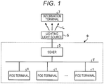
- FIG. 1 is a diagram showing an abnormality monitoring system according to a first embodiment.
- an abnormality monitoring system 9 includes a plurality of POS terminals 1 and one server 3. Further, in FIG. 1 , a lighting light source 5 is provided in addition to the abnormality monitoring system.
- Each POS terminal 1 and server 3 are connected to each other via a network T such as a local area network (LAN).
- LAN local area network
- the POS terminal 1 will be described.
- One or a plurality of POS terminals 1 are installed in a checkout section in a store.
- the POS terminal 1 is used for selling commodities displayed in the store.
- the POS terminal 1 includes a self-type POS terminal operated by a customer.
- the POS terminal 1 includes a semi-self type POS terminal in which a clerk operates sales registration and a customer performs accounting operations.
- the POS terminal 1 acquires commodity information of a commodity purchased by a customer to execute sales registration processing related to the commodity. Further, the POS terminal 1 executes settlement processing based on a settlement operation.
- the sales registration processing refers to processing of reading commodity information (commodity name, price, and the like) of a commodity, displaying the commodity information of the read commodity, and storing the commodity information in a commodity information section 131 (see FIG. 2 ) based on commodity code that identifies the commodity acquired by the POS terminal 1 based on the symbol or wireless tag attached to the commodity.
- the settlement processing refers to processing for displaying the total amount and tax amount related to transactions based on the commodity information stored in the commodity information section 131 with the sales registration processing, calculating and displaying changes based on deposits received from customers, and issuing receipts printed with commodity information and settlement information (total amount, deposit amount, change amount, and the like) by driving a printer 24 (see FIG. 2 ).
- the POS terminal 1 monitors whether an abnormality occurred in the own device during the period from when the power is turned on to when the power is turned off. Further, the POS terminal 1 transmits abnormality information, which is operation log information indicating an abnormality occurring in the own device, to the server 3. In addition, the POS terminal 1 modulates the frequency of a lighting light source (LED) as a backlight that is provided on a display unit of the own device to brightly illuminate the display unit and outputs the modulated abnormality information from the display unit.
- LED lighting light source
- the server 3 collects commodity information and settlement information related to the commodities sold at each POS terminal 1 and manages the sales of the store.
- the server 3 receives abnormality information from each POS terminal 1.
- the server 3 also controls a lighting light source (for example, light emitting diode (LED) lighting) that illuminates the interior of the store.
- a lighting light source for example, light emitting diode (LED) lighting
- LED light emitting diode
- a plurality of lighting light sources are installed in a store on the ceiling of the store and brightly illuminate the entrance and exit of the store, a display section on which commodities are displayed, a checkout section, and the like from above.
- the LED can particularly increase the modulation frequency among the lighting light sources. Therefore, when using an LED as a lighting light source, the lighting light source can be used as lighting in the store, and at the same time, can modulate the intensity in a high-frequency band that does not cause flickering to the eyes of people in the store.
- the lighting light source of which intensity is modulated in this way emits light L into the store to illuminate the store brightly, and the lighting light source of which intensity is modulated in this way is imaged by a camera provided in an information terminal 7 such as a smartphone, for example, the light L emitted from the lighting light source is received.
- the information terminal 7 that received the light L analyzes the modulated abnormality information included in the light L and displays the analyzed abnormality information on the display unit.
- a maintenance person who came to the maintenance inspection of the POS terminal 1 enters the store and images the lighting light source with the camera of the information terminal 7 to specify the POS terminal 1 where an abnormality occurred.
- the maintenance person can recognize when and what kind of abnormality occurred in the POS terminal 1. For this reason, the maintenance person can recognize the POS terminal 1 in which an abnormality occurred without checking the abnormality information of the POS terminal 1 in the server 3.
- the server 3 outputs a signal for modulating the frequency of the lighting light source based on the abnormality information received from the POS terminal 1.
- the abnormality information of the POS terminal 1 to be included in the modulation frequency contains, for example, store information for specifying a store, a terminal number for specifying the POS terminal 1, the date and time when an abnormality occurred, an item for specifying the type of abnormality, actual data, and the like.
- the abnormality information contains information indicating whether the actual data is reached or exceeded a preset first threshold (threshold set as a near limit value that is not yet an abnormality value but approached the abnormality value) or whether the actual data reached or exceeded a preset second threshold (threshold set as a limit value that reached the abnormality value).
- FIG. 2 is a block diagram showing a hardware configuration of the POS terminal 1.
- the POS terminal 1 includes a central processing unit (CPU) 11, a read only memory (ROM) 12, a random-access memory (RAM) 13, a memory unit 14, and the like.
- the CPU 11 is a control subject.
- the ROM 12 stores various programs.
- the RAM 13 develops programs and various data.
- the memory unit 14 stores various programs.
- the CPU 11, the ROM 12, the RAM 13, and the memory unit 14 are connected to each other via a bus 15.
- the CPU 11, the ROM 12, and the RAM 13 constitute a control unit 100. That is, the control unit 100 executes control processing of the POS terminal 1 described later by the CPU 11 operating according to the control program stored in the ROM 12 or the memory unit 14 and developed in the RAM 13.
- the RAM 13 includes a commodity information section 131.
- the commodity information section 131 stores commodity information (commodity name, commodity price, and the like) of the commodity that underwent sales registration processing.
- the memory unit 14 is configured with a solid state drive (SDD), a hard disc drive (HDD), a flash memory, or the like and maintains the stored contents even when the power is shut off.
- the memory unit 14 includes a control program section 141, an abnormality information section 142, and a modulation information section 143.
- the control program section 141 stores a control program for controlling the POS terminal 1.
- the abnormality information section 142 stores abnormality information related to the abnormality of the POS terminal 1.
- the abnormality information section 142 will be described later with reference to FIG. 3 .
- the modulation information section 143 stores conversion information for modulating abnormality information. In the first embodiment, description will be made assuming that the memory unit 14 is an SSD.
- the control unit 100 includes a manipulation unit 21, a clerk display unit 22, a customer display unit 23, a printer 24, a card reader 25, and a barcode reader 26 via the bus 15 and a controller 16.
- the manipulation unit 21 includes a numeric keypad and function keys and is a keyboard for operation by a clerk or a customer.
- the clerk display unit 22 displays commodity information and settlement information to the clerk.
- the clerk display unit 22 modulates a light source (for example, LED) as a backlight that illuminates a screen displaying commodity information and settlement information at high speed and outputs the modulated abnormality information in the POS terminal 1 from the screen.
- the customer display unit 23 displays commodity information and settlement information to the customer.
- the printer 24 uses, for example, a thermal head provided with a heating element, prints commodity information and settlement information on a long thermal paper, and issues a receipt.
- the card reader 25 reads customer information from a card (for example, a credit card) used for settlement processing.
- the barcode reader 26 reads a symbol such as a barcode attached to the commodity.
- control unit 100 is connected to a communication I/F 27 and a timer 17 via the bus 15.
- the communication I/F 27 can exchange information with the server 3 via the network T.
- the timer 17 measures the current date and time.
- FIG. 3 is a diagram showing information stored in the abnormality information section 142.
- the abnormality information section 142 includes an item section 1421, an actual data section 1422, a first threshold section 1423, and a second threshold section 1424.
- the item section 1421 stores an item that is abnormal.
- the actual data section 1422 stores actual data monitored for the item.
- the control unit 100 stores new actual data every time the actual data is updated.
- the first threshold section 1423 stores the first threshold that did not reach an abnormality value but approached the abnormality value.
- the second threshold section 1424 stores the second threshold that is the abnormality value.
- An abnormality 142a is an abnormality relating to the number of times that information is stored in SSD.
- the item section 1421 stores an item representing "SSD use count".
- the actual data section 1422 accumulates and stores the number of times that information was stored in the SSD so far.
- the number of times that information is stored in the SSD has an upper limit, and the abnormality value is reached when the upper limit is reached or exceeded.
- the control unit 100 updates and stores the number of times that information is stored in the SSD stored in the actual data section 1422.
- the control unit 100 determines that an abnormality occurred.
- the first threshold section 1423 stores the number of times that information is stored in the SSD that is smaller than the upper limit value but is very close to the upper limit value as the first threshold.
- the second threshold section 1424 stores the number of times the upper limit value is stored as an abnormality value.
- An abnormality 142b is an abnormality relating to the number of lines printed on the receipt paper of the printer 24. As the printer 24 prints characters on the paper, the thermal head gradually wears, and there is a risk that the heating element will eventually break. Therefore, the number of lines printed on the receipt paper by the printer 24 is monitored, and it is determined whether an abnormality value that may cause break of the heating element was reached or exceeded if printing is performed more than this.
- the item section 1421 in the abnormality 142b stores an item representing "number of printed lines".
- the actual data portion 1422 accumulates and stores the number of lines printed by the printer 24 so far.
- the control unit 100 updates the number of print lines stored in the actual data section 1422 every time one line is printed on the paper by the printer 24.
- the first threshold section 1423 stores the number of times that the number of printed lines of the printer 24 is smaller than the abnormality value but is very close to the abnormality value as the first threshold.
- the second threshold section 1424 stores the number of printed lines that is the abnormality value.
- the control unit 100 determines, for each item, whether the actual data stored in the actual data section 1422 reached or exceeded the first threshold stored in the first threshold section 1423. If it is determined that the first threshold was reached or exceeded, the control unit 100 outputs message information (for example, a message such as "It is almost time to replace the thermal head.") indicating that the first threshold was reached or exceeded. In addition, if it is determined that the second threshold was reached or exceeded, the control unit 100 outputs message information (for example, a message such as "It is time to replace the thermal head. Please replace it.") indicating that the second threshold was reached or exceeded.
- message information for example, a message such as "It is time to replace the thermal head. Please replace it.
- FIG. 4 is a block diagram showing a hardware configuration of the server 3.
- the server 3 includes a CPU 31, a ROM 32, a RAM 33, a memory unit 34, and the like.
- the CPU 31 is a control entity.
- the ROM 32 stores various programs.
- the RAM 33 develops programs and various data.
- the memory unit 34 stores various programs.
- the CPU 31, the ROM 32, the RAM 33, and the memory unit 34 are connected to each other via a bus 35.
- the CPU 31, the ROM 32, and the RAM 33 constitute a control unit 300. That is, the control unit 300 executes control processing of the server 3 described later by the CPU 31 operating according to the control program stored in the ROM 32 or the memory unit 34 and developed in the RAM 33.
- the RAM 33 includes an abnormality information storage unit 331.
- the abnormality information storage unit 331 stores abnormality information for each POS terminal 1 received from the POS terminal 1.
- the memory unit 34 is configured with an SSD, an HDD, a flash memory, and the like and maintains the stored contents even when the power is shut off.
- the memory unit 34 includes a control program section 341 and a modulation information section 342.
- the control program section 341 stores a control program for controlling the server 3.
- the modulation information section 342 stores conversion information for modulating abnormality information.
- the control unit 300 includes a manipulation unit 37, a display unit 38, and the lighting light source 5 via the bus 35 and a controller 36.
- the manipulation unit 37 is a keyboard including numeric keys and function keys.
- the display unit 38 displays information to an operator of the server 3.
- the lighting light source 5 is a lighting device including a power supply unit and a control unit. When the lighting light source 5 receives the modulated abnormality information output from the server 3, the lighting light source 5 blinks the LED at a modulated frequency at high speed.
- control unit 300 is connected to a communication I/F 40 via the bus 35.
- the communication I/F 40 can exchange information with the POS terminal 1 via the network T.
- FIG. 5 is a functional block diagram showing a functional configuration of the abnormality monitoring system 9.
- the POS terminal 1 in the abnormality monitoring system 9 functions as a monitoring unit 101, an abnormality information acquisition unit 102, an abnormality transmission unit (information transmission unit) 103, a second modulation unit 104, a display control unit 105, a release determination unit 106, and a release transmission unit 107 by following the control program stored in the control program section 141 and developed in the RAM 13.
- the server 3 in the abnormality monitoring system 9 functions as a reception unit 301, a first modulation unit 302, and a lighting control unit 303 by following the control program stored in the control program section 341 and developed in the RAM 33.
- the monitoring unit 101 monitors whether there is an abnormality in the own POS terminal 1. Specifically, the monitoring unit 101 monitors whether there is an abnormality in the own POS terminal 1 from when the own POS terminal 1 is turned on until the power is turned off.
- the abnormality information acquisition unit 102 acquires abnormality information of a portion that is abnormal as a result of monitoring by the monitoring unit 101. Specifically, when the monitoring unit 101 monitored that the actual data reached or exceeded the first threshold for the abnormality 142a and abnormality 142b in the abnormality information section 142, the abnormality information acquisition unit 102 recognizes that there is an abnormality and acquires abnormality information.
- the abnormality information acquisition unit 102 acquires store information that identifies the store, the terminal number of the POS terminal 1, the date and time when an abnormality occurred, an item (information that indicates the number of times that SSD is used) that identifies the type of abnormality, the number of times that information is stored in SSD as actual data that reached or exceeded the first threshold, message information indicating that the number of times that information is stored reached or exceeded the first threshold, as abnormality information.
- the abnormality information acquisition unit 102 acquires store information that identifies the store, the terminal number of the POS terminal 1, the date and time when the abnormality occurred, an item that identifies the type of abnormality (the number of lines printed by the printer 24), the number of lines printed by the printer 24 as actual data that reached or exceeded the first threshold, message information indicating that the number of printed lines reached or exceeded the first threshold, and the like, as abnormality information.
- the abnormality information acquisition unit 102 acquires abnormality information when the actual data being monitored reaches or exceeds the second threshold.
- the abnormality information acquisition unit 102 acquires store information that identifies the store, the terminal number of the POS terminal 1, the date and time when an abnormality occurred, an item (information that indicates the number of times that SSD is used) that identifies the type of abnormality, the number of times that information is stored in SSD as actual data that reached or exceeded the second threshold, message information indicating that the number of times that information is stored reached or exceeded the second threshold, as abnormality information.
- the abnormality information acquisition unit 102 acquires store information that identifies the store, the terminal number of the POS terminal 1, the date and time when the abnormality occurred, an item that identifies the type of abnormality (the number of lines printed by the printer 24), the number of lines printed by the printer 24 as actual data that reached or exceeded the second threshold, message information indicating that the number of printed lines reached or exceeded the second threshold, and the like as abnormality information.
- the abnormality transmission unit (information transmission unit) 103 detects an abnormality of the own POS terminal 1
- the abnormality transmission unit transmits abnormality information related to the abnormality to the server 3.
- the abnormality transmission unit 103 transmits the abnormality information to the server 3 when the abnormality information acquisition unit 102 acquires the abnormality information.
- the second modulation unit 104 generates frequency information indicating the abnormality based on the abnormality information. Specifically, the second modulation unit 104 generates frequency information including abnormality information indicating the abnormality in a high-frequency band that does not cause flickering to the eyes of people for the abnormality information acquired by the abnormality information acquisition unit 102, based on the conversion information stored in the modulation information section 143.
- the display control unit 105 Based on the frequency information generated by the second modulation unit 104, the display control unit 105 blinks and displays the information of the clerk display unit 22. Specifically, the display control unit 105 blinks the backlight of the clerk display unit 22 configured with the LED based on the frequency information generated by the second modulation unit 104.
- the release determination unit 106 determines whether the abnormality was released when the monitoring unit 101 monitors that the abnormality was released in the POS terminal 1.
- the release transmission unit 107 transmits the abnormality release to the server 3 when the abnormality is released. Specifically, the release transmission unit 107 transmits abnormality release information indicating abnormality release to the server 3 for the item determined to be released by the release determination unit 106.
- the reception unit 301 accepts reception of abnormality information indicating an abnormality that occurred in the POS terminal 1. Specifically, the reception unit 301 receives the abnormality information transmitted by the abnormality transmission unit 103 and stores the abnormality information in the abnormality information storage unit 331, thereby accepting the reception of the abnormality information. In addition, the reception unit 301 receives the abnormality release information transmitted by the release transmission unit 107.
- the first modulation unit 302 generates frequency information indicating the abnormality based on the abnormality information received by the reception unit 301. Specifically, the first modulation unit 302 modulates the abnormality information received by the reception unit 301 based on the conversion information stored in the modulation information section 342 to indicate an abnormality and generates frequency information including abnormality information indicating the abnormality in a high-frequency band that does not cause flickering to the eyes of people.
- the lighting control unit 303 Based on the frequency information generated by the first modulation unit 302, the lighting control unit 303 blinks the lighting light source provided in the store to illuminate the store. Specifically, the lighting control unit 303 blinks the LED, which is a lighting light source used as a lighting device, at a high frequency that does not cause flickering to the eyes of people based on the frequency information generated by the first modulation unit 302. Further, the lighting control unit 303 stops blinking at a high frequency based on the abnormality release information received by the reception unit 301.
- FIG. 6 is a flowchart showing a flow of control processing of the POS terminal 1.
- the control unit 100 of the POS terminal 1 determines whether the power of the POS terminal 1 is turned on (ACT 11). If it is determined that the power of the POS terminal 1 is turned on (Yes in ACT 11), the monitoring unit 101 starts monitoring whether there is an abnormality in the own POS terminal 1 (ACT 12). Then, the control unit 100 returns to ACT 11.
- the control unit 100 determines whether the barcode reader 26 read the symbol attached to the commodity and acquired the commodity code (ACT 21). If it is determined that the commodity code was acquired (Yes in ACT 21), the control unit 100 executes sales registration processing based on the acquired commodity code and stores commodity information in the commodity information section 131 (ACT 22). Then, the control unit 100 returns to ACT 11.
- the control unit 100 determines whether a sum key (not shown) included in the manipulation unit 21 was operated (ACT 23). If it is determined that the sum key was operated (Yes in ACT 23), the control unit 100 executes settlement processing based on the commodity information stored in the commodity information section 131 (ACT 24). Then, the control unit 100 returns to ACT 11.
- the control unit 100 determines whether information is newly stored in the SDD or printing is newly performed (ACT 25). If it is determined that information is newly stored in the SDD or printing is newly performed (Yes in ACT 25), the control unit 100 updates the actual data stored in the actual data section 1422 to the latest data. Then, the control unit 100 returns to ACT 11.
- the control unit 100 determines whether an abnormality occurred in the POS terminal 1 (ACT 31). For example, when the actual data stored in the actual data section 1422 reaches or exceeds the first threshold stored in the first threshold section 1423, the control unit 100 determines that an abnormality occurred in the POS terminal 1. In addition, when the actual data stored in the actual data section 1422 reaches or exceeds the second threshold stored in the second threshold section 1424, the control unit 100 determines that an abnormality occurred in the POS terminal 1.
- the abnormality information acquisition unit 102 acquires the abnormality information of the abnormal portion and stores the information in the abnormality information section 142 (ACT 32).
- the abnormality transmission unit 103 transmits the acquired abnormality information to the server 3 (ACT 33).
- the second modulation unit 104 generates frequency information indicating the abnormality based on the acquired abnormality information (ACT 34). That is, the second modulation unit 104 generates frequency information in a high-frequency band represented by the abnormality information based on the conversion information stored in the modulation information section 143 for the acquired abnormality information (ACT 34).
- the display control unit 105 displays information while blinking the backlight of the clerk display unit 22 (ACT 35). Then, the control unit 100 returns to ACT 11.
- the release determination unit 106 determines whether an abnormality was released (ACT 36). In an abnormal state, for example, when the SSD is replaced with a new one, or when the thermal head of the printer 24 is replaced with a new one, the release determination unit 106 determines that the abnormality was released and clears the actual data stored in the actual data section 1422.
- the display control unit 105 stops the display processing of blinking the information displayed on the clerk display unit 22 (specifically, the backlight of the clerk display unit 22) performed in ACT 35 (ACT 37). Then, when the abnormality is released, the release transmission unit 107 transmits information on the abnormality release to the server 3 (ACT 38). Then, the control unit 100 clears the abnormality information stored in the abnormality information section 142 and of which abnormality was released (ACT 39). Then, the control unit 100 returns to ACT 11.
- the control unit 100 determines whether the power of the POS terminal 1 is turned off (ACT 41). If it is determined that the power of the POS terminal 1 is turned off (Yes in ACT 41), the control unit 100 ends the monitoring started in ACT 12 (ACT 42). Then, the control unit 100 returns to ACT 11. If it is determined that the POS terminal 1 is not turned off (No in ACT 41), the control unit 100 returns to ACT 11.
- FIG. 7 is a flowchart showing the flow of control processing of the server 3.
- the control unit 300 of the server 3 determines whether or not commodity information and settlement information related to the sales registration processing of the commodity were received (ACT 51). If it is determined that the commodity information and the settlement information are received (Yes in ACT 51), the control unit 300 accumulates the received commodity information and the settlement information and stores the information in the memory unit 34 and manages the sales information at the store. (ACT 52). Then, the control unit 300 returns to ACT 51.
- the control unit 300 determines whether the abnormality information is received from the POS terminal 1 (ACT 61). If it is determined that the abnormality information is received from the POS terminal 1 (Yes in ACT 61), the reception unit 301 stores the abnormality information received from the POS terminal 1 in the abnormality information storage unit 331 and accepts the information (ACT 62). Next, the first modulation unit 302 generates frequency information including abnormality information indicating the abnormality in the high-frequency band indicating the abnormality based on the abnormality information received by the reception unit 301 (ACT 63).
- the lighting control unit 303 blinks the LED, which is a lighting light source provided in the store to illuminate the store, at a high frequency that does not cause flickering to the eyes of people (ACT 64). Then, the control unit 300 returns to ACT 51.
- the control unit 300 determines whether abnormality release information was received from the POS terminal 1 (ACT 71). If it is determined that the abnormality release information was received (Yes in ACT 71), the control unit 300 stops the blinking of the LED at a high frequency (ACT 72). Then, the control unit 300 returns to ACT 51. In addition, if it is determined that the abnormality release information is not received (No in ACT 71), the control unit 300 returns to ACT 51.
- the POS terminal 1 transmits abnormality information to the server 3, and the server 3 blinks the lighting light source based on the received abnormality information based on the frequency information generated in a high-frequency band. Therefore, the maintenance person who entered the store can obtain the abnormality information of the information processing device without spending time by imaging the lighting light source with the information terminal 7.
- the second embodiment is characterized in that a camera C that captures the screen of the clerk display unit 22 of the POS terminal 1 is provided.
- the camera C is configured with, for example, a charge coupled device (CCD) image sensor.
- CCD charge coupled device
- the camera C originally images the manipulation unit 21 of the POS terminal 1 and the clerk display unit 22 in order to check the clerk's unauthorized operation at the POS terminal 1.
- the camera C images the blinking of the screen in the high-frequency band displayed by the display control unit 105 in the processing of ACT 34 as modulation information. Then, the lighting light source is blinked based on the imaged modulation information.
- FIG. 8 is a functional block diagram showing a functional configuration of the abnormality monitoring system 9 according to the second embodiment.
- the POS terminal 1 in the abnormality monitoring system 9 functions as a monitoring unit 101, an abnormality information acquisition unit 102, a second modulation unit 104, and a display control unit 105 by following the control program stored in the control program section 141 and developed in the RAM 13.
- the server 3 in the abnormality monitoring system 9 functions as a reception unit 304, and the lighting control unit 305 by following the control program stored in the control program section 341 and developed in the RAM 33.
- the reception unit 304 receives the modulation information captured by the camera C. Specifically, the reception unit 304 accepts reception of modulation information captured by the camera C, generated by the second modulation unit 104, and blinked by the display control unit 105.
- the lighting control unit 305 Based on the modulation information imaged by the camera C, the lighting control unit 305 blinks the lighting light source provided in the store to illuminate the store at a high frequency that does not cause flickering to the eyes of people.
- FIG. 9 is a flowchart showing a flow of control processing of the POS terminal 1 according to the second embodiment.
- the POS terminal 1 of the second embodiment does not execute the processings of ACT 33 and ACT 38 in FIG. 6 compared to the POS terminal 1 of the first embodiment.
- the display control unit 105 outputs the information modulated by the second modulation unit 104 and the information is captured by the camera C, there is no need to separately transmit abnormality information from the POS terminal 1 to the server 3.
- the server 3 receives the modulation information from the POS terminal 1, it is not necessary for the server 3 to modulate the abnormality information and generate frequency information in a high-frequency band.
- the abnormality information acquisition unit 102 acquires the abnormality information of an abnormal portion as a result of monitoring by the monitoring unit 101 and stores the information in the abnormality information section 142 (ACT 32).
- the second modulation unit 104 generates frequency information in a high-frequency band indicating the abnormality based on the acquired abnormality information. That is, the second modulation unit 104 generates frequency information in a high-frequency band represented by the abnormality information based on the conversion information stored in the modulation information section 143 for the acquired abnormality information (ACT 34).
- the display control unit 105 Based on the frequency information generated by the second modulation unit 104, the display control unit 105 blinks and displays information to be displayed on the clerk display unit 22 (specifically, the backlight of the clerk display unit 22). (ACT 35). Then, the control unit 100 returns to ACT 11.
- the camera C images the clerk display unit 22 and captures the modulation information in which the backlight displayed in ACT 35 blinks.
- FIG. 10 is a flowchart showing the flow of server control processing.
- the server 3 determines whether the reception unit 304 received modulation information (ACT 81). If the reception unit 304 determines that the modulation information was received (Yes in ACT 81), the lighting control unit 303 causes the LED, which is a lighting light source provided in the store to illuminate the store, to blink at a high frequency that does not cause flickering to the eyes of people (ACT 64), based on the modulation information captured by the camera C. Then, the control unit 300 returns to ACT 51. When the reception unit 304 determines that the modulation information is not received (No in ACT 81), the control unit 300 performs the determination in ACT 71.
- the POS terminal 1 modulates the abnormality information and displays the information on the clerk display unit 22, the camera C captures the modulation information displayed, and the server 3 blinks the lighting light source based on the modulation information captured by the camera C. Therefore, the maintenance person who entered the store can obtain the abnormality information of the information processing device without spending time by imaging the lighting light source with the information terminal 7.
- an LED is used as the lighting light source.
- the exemplary embodiment is not limited thereto, and any lighting light source that can be modulated in a high-frequency band that the eyes of people do not feel flickering may be used.
- the backlight of the clerk display unit 22 blinks in a high-frequency band.
- the exemplary embodiment is not limited thereto, and the backlight of the customer display unit 23 may blink at a high frequency.
- the abnormality information is modulated and displayed on the clerk display unit 22 (second modulation unit 104, display control unit 105).
- the exemplary embodiment is not limited thereto, and in the first embodiment, the second modulation unit 104 and the display control unit 105 are not essential requirements.
- the abnormal state is described as two types of abnormality 142a and abnormality 142b.
- the exemplary embodiment is not limited thereto, and the abnormal state may be an abnormality other than the abnormality 142a and the abnormality 142b.
- the abnormality may be an abnormality related to an error in addition to the abnormality related to the lifetime.
- the exemplary embodiment is not limited thereto, and one or more POS terminals 1 may be used.
- the exemplary embodiment is not limited thereto, and for example, by sending operation log information together with the ID of the device in a normal state, the maintenance person who enters the store can obtain an operation log of the information processing device without spending time by imaging the lighting light source with the information terminal 7.
- lighting and lighting such as backlight are blinked.
- operation log information such as an abnormal state can be directly acquired by modulating the light emission intensity of a power lamp of an individual device such as a printer.
Landscapes
- Engineering & Computer Science (AREA)
- Physics & Mathematics (AREA)
- General Physics & Mathematics (AREA)
- Business, Economics & Management (AREA)
- Theoretical Computer Science (AREA)
- Accounting & Taxation (AREA)
- Signal Processing (AREA)
- Computer Networks & Wireless Communication (AREA)
- Finance (AREA)
- Electromagnetism (AREA)
- Environmental & Geological Engineering (AREA)
- General Engineering & Computer Science (AREA)
- Quality & Reliability (AREA)
- General Business, Economics & Management (AREA)
- Strategic Management (AREA)
- Cash Registers Or Receiving Machines (AREA)
- Audible And Visible Signals (AREA)
- Alarm Systems (AREA)
- Selective Calling Equipment (AREA)
- Optical Communication System (AREA)
Abstract
According to one embodiment, a monitoring system includes an information processing device and a server, in which the information processing device includes an information transmission unit that transmits information related to operation log information to the server when the operation log information of the information processing device is detected, and the server includes a reception unit that receives the operation log information transmitted by the information transmission unit, a first operation modulation unit that generates frequency information indicating an operation of the information processing device based on the operation log information received by the reception unit, and a lighting control unit that blinks a lighting light source provided in a store to illuminate the store based on the frequency information generated by the first operation modulation unit.
Description
- Embodiments described herein relate generally to a monitoring system.
- In the related art, abnormality information related to the lifetime of each part of a point of sales (POS) terminal installed in a store or abnormal operation is managed by a server connected to the POS terminal. The POS terminal transmits the own abnormality information thereof to the server via a network. For this reason, when a maintenance person who maintains POS terminals visits a store, it is necessary to check the information displayed on the server installed in the backyard to check the abnormality information of each POS terminal. Therefore, it takes significant and inconvenient time for the maintenance person to check the abnormality information of each POS terminal.
-
-
FIG. 1 is a diagram showing an abnormality monitoring system according to a first embodiment; -
FIG. 2 is a block diagram showing a hardware configuration of a POS terminal; -
FIG. 3 is a diagram showing information stored in an abnormality information section; -
FIG. 4 is a block diagram showing a hardware configuration of a server; -
FIG. 5 is a functional block diagram showing a functional configuration of the abnormality monitoring system; -
FIG. 6 is a flowchart showing a flow of control processing of the POS terminal; -
FIG. 7 is a flowchart showing a flow of server control processing; -
FIG. 8 is a functional block diagram showing a functional configuration of an abnormality monitoring system according to a second embodiment; -
FIG. 9 is a flowchart showing a flow of control processing of the POS terminal; and -
FIG. 10 is a flowchart showing a flow of server control processing. - Embodiments provide a monitoring system in which the maintenance person can obtain operation information of an information processing device without having to spend time in a store.
- In general, according to one embodiment, a monitoring system includes an information processing device and a server, in which the information processing device includes an information transmission unit that transmits information related to operation log information to the server when the operation log information of the information processing device is detected, and the server includes a reception unit that receives the operation log information transmitted by the information transmission unit, a first operation modulation unit that generates frequency information indicating an operation of the information processing device based on the operation log information received by the reception unit, and a lighting control unit that blinks a lighting light source provided in a store to illuminate the store based on the frequency information generated by the first operation modulation unit.
- Preferably, the information processing device further comprises a display that displays information, a second modulation component that generates frequency information indicating the operation based on the operation log information, and a display control component that blinks and displays the display based on the frequency information generated by the second modulation component.
- Preferably, the lighting control component causes the lighting light source to blink at a predetermined frequency not based on the frequency information indicating the operation when the operation log information is not received.
- Preferably, the operation log information comprises a description of an abnormality of the information processing device or an identity of an abnormality of the information processing device.
- Preferably, the operation log information comprises a date and time of an abnormality of the information processing device.
- Preferably, the information processing device is a POS terminal.
- The system may further comprise a plurality of information processing devices.
- Preferably, the information processing device and server are connected by a wireless network.
- The present invention further relates to a monitoring system, comprising: an information processing device; a server; and a camera.
- Preferably, the information processing device further comprises a display that displays information.
- Preferably, the information processing device further comprises a modulation component that generates frequency information indicating an operation based on operation log information related to the operation when the operation of the information processing device is detected.
- Preferably, the information processing device further comprises a display control component that blinks and displays the display based on the frequency information generated by the modulation component.
- Preferably, the camera captures modulation information of the display blinked and displayed by the display control component.
- Preferably, the server comprises a lighting control component that blinks a lighting light source that is provided in a store to illuminate the store, based on the modulation information captured by the camera.
- Preferably, the lighting control component blinks the lighting light source at a predetermined frequency not based on the frequency information indicating the operation when the camera is not capturing the modulation information.
- Preferably, the camera is comprised in a smartphone.
- Preferably, the operation log information comprises a description of an abnormality of the information processing device or an identity of an abnormality of the information processing device.
- Preferably, the operation log information comprises a date and time of an abnormality of the information processing device.
- Preferably, the information processing device is a POS terminal.
- The system may further comprise a plurality of information processing devices.
- Preferably, the information processing device and server are connected by a wireless network.
- The present invention also relates to a monitoring method, comprising: detecting and transmitting information related to operation log information of an information processing device to a server when the operation log information of the information processing device; receiving by the server the operation log information transmitted; generating frequency information indicating an operation of the information processing device based on the operation log information received; and blinking a lighting light source provided in a store to illuminate the store based on the frequency information generated.
- The method may further comprise: displaying information;
generating frequency information indicating the operation based on the operation log information; and
blinking and displaying the displayed information based on the frequency information generated. - The method may further comprise: causing the lighting light source to blink at a predetermined frequency not based on the frequency information indicating the operation when the operation log information is not received.
- Preferably, the operation log information comprises a date and time of an abnormality of the information processing device.
- Hereinafter, an abnormality monitoring system according to a first embodiment and a second embodiment will be described with reference to drawings. In the first embodiment and the second embodiment, a POS terminal will be described as an example of an information processing device. The exemplary embodiment is not limited to the embodiments described below.
-
FIG. 1 is a diagram showing an abnormality monitoring system according to a first embodiment. As shown inFIG. 1 , anabnormality monitoring system 9 includes a plurality ofPOS terminals 1 and oneserver 3. Further, inFIG. 1 , alighting light source 5 is provided in addition to the abnormality monitoring system. EachPOS terminal 1 andserver 3 are connected to each other via a network T such as a local area network (LAN). - First, the
POS terminal 1 will be described. One or a plurality ofPOS terminals 1 are installed in a checkout section in a store. ThePOS terminal 1 is used for selling commodities displayed in the store. ThePOS terminal 1 includes a self-type POS terminal operated by a customer. ThePOS terminal 1 includes a semi-self type POS terminal in which a clerk operates sales registration and a customer performs accounting operations. ThePOS terminal 1 acquires commodity information of a commodity purchased by a customer to execute sales registration processing related to the commodity. Further, thePOS terminal 1 executes settlement processing based on a settlement operation. - Here, the sales registration processing refers to processing of reading commodity information (commodity name, price, and the like) of a commodity, displaying the commodity information of the read commodity, and storing the commodity information in a commodity information section 131 (see
FIG. 2 ) based on commodity code that identifies the commodity acquired by thePOS terminal 1 based on the symbol or wireless tag attached to the commodity. The settlement processing refers to processing for displaying the total amount and tax amount related to transactions based on the commodity information stored in the commodity information section 131 with the sales registration processing, calculating and displaying changes based on deposits received from customers, and issuing receipts printed with commodity information and settlement information (total amount, deposit amount, change amount, and the like) by driving a printer 24 (seeFIG. 2 ). - The
POS terminal 1 monitors whether an abnormality occurred in the own device during the period from when the power is turned on to when the power is turned off. Further, thePOS terminal 1 transmits abnormality information, which is operation log information indicating an abnormality occurring in the own device, to theserver 3. In addition, thePOS terminal 1 modulates the frequency of a lighting light source (LED) as a backlight that is provided on a display unit of the own device to brightly illuminate the display unit and outputs the modulated abnormality information from the display unit. - The
server 3 collects commodity information and settlement information related to the commodities sold at eachPOS terminal 1 and manages the sales of the store. Theserver 3 receives abnormality information from eachPOS terminal 1. Theserver 3 also controls a lighting light source (for example, light emitting diode (LED) lighting) that illuminates the interior of the store. For example, a plurality of lighting light sources are installed in a store on the ceiling of the store and brightly illuminate the entrance and exit of the store, a display section on which commodities are displayed, a checkout section, and the like from above. - The LED can particularly increase the modulation frequency among the lighting light sources. Therefore, when using an LED as a lighting light source, the lighting light source can be used as lighting in the store, and at the same time, can modulate the intensity in a high-frequency band that does not cause flickering to the eyes of people in the store. When the lighting light source of which intensity is modulated in this way emits light L into the store to illuminate the store brightly, and the lighting light source of which intensity is modulated in this way is imaged by a camera provided in an
information terminal 7 such as a smartphone, for example, the light L emitted from the lighting light source is received. Theinformation terminal 7 that received the light L analyzes the modulated abnormality information included in the light L and displays the analyzed abnormality information on the display unit. By doing in this way, for example, a maintenance person who came to the maintenance inspection of thePOS terminal 1 enters the store and images the lighting light source with the camera of theinformation terminal 7 to specify thePOS terminal 1 where an abnormality occurred. In addition, the maintenance person can recognize when and what kind of abnormality occurred in thePOS terminal 1. For this reason, the maintenance person can recognize thePOS terminal 1 in which an abnormality occurred without checking the abnormality information of thePOS terminal 1 in theserver 3. - The
server 3 outputs a signal for modulating the frequency of the lighting light source based on the abnormality information received from thePOS terminal 1. The abnormality information of thePOS terminal 1 to be included in the modulation frequency contains, for example, store information for specifying a store, a terminal number for specifying thePOS terminal 1, the date and time when an abnormality occurred, an item for specifying the type of abnormality, actual data, and the like. In addition, the abnormality information contains information indicating whether the actual data is reached or exceeded a preset first threshold (threshold set as a near limit value that is not yet an abnormality value but approached the abnormality value) or whether the actual data reached or exceeded a preset second threshold (threshold set as a limit value that reached the abnormality value). - From here, the hardware of the
POS terminal 1 will be described.FIG. 2 is a block diagram showing a hardware configuration of thePOS terminal 1. As shown inFIG. 2 , thePOS terminal 1 includes a central processing unit (CPU) 11, a read only memory (ROM) 12, a random-access memory (RAM) 13, a memory unit 14, and the like. TheCPU 11 is a control subject. TheROM 12 stores various programs. The RAM 13 develops programs and various data. The memory unit 14 stores various programs. TheCPU 11, theROM 12, the RAM 13, and the memory unit 14 are connected to each other via abus 15. TheCPU 11, theROM 12, and the RAM 13 constitute acontrol unit 100. That is, thecontrol unit 100 executes control processing of thePOS terminal 1 described later by theCPU 11 operating according to the control program stored in theROM 12 or the memory unit 14 and developed in the RAM 13. - The RAM 13 includes a commodity information section 131. The commodity information section 131 stores commodity information (commodity name, commodity price, and the like) of the commodity that underwent sales registration processing.
- The memory unit 14 is configured with a solid state drive (SDD), a hard disc drive (HDD), a flash memory, or the like and maintains the stored contents even when the power is shut off. The memory unit 14 includes a control program section 141, an
abnormality information section 142, and a modulation information section 143. The control program section 141 stores a control program for controlling thePOS terminal 1. Theabnormality information section 142 stores abnormality information related to the abnormality of thePOS terminal 1. Theabnormality information section 142 will be described later with reference toFIG. 3 . The modulation information section 143 stores conversion information for modulating abnormality information. In the first embodiment, description will be made assuming that the memory unit 14 is an SSD. - The
control unit 100 includes amanipulation unit 21, aclerk display unit 22, acustomer display unit 23, aprinter 24, acard reader 25, and abarcode reader 26 via thebus 15 and acontroller 16. Themanipulation unit 21 includes a numeric keypad and function keys and is a keyboard for operation by a clerk or a customer. Theclerk display unit 22 displays commodity information and settlement information to the clerk. Theclerk display unit 22 modulates a light source (for example, LED) as a backlight that illuminates a screen displaying commodity information and settlement information at high speed and outputs the modulated abnormality information in thePOS terminal 1 from the screen. Thecustomer display unit 23 displays commodity information and settlement information to the customer. Theprinter 24 uses, for example, a thermal head provided with a heating element, prints commodity information and settlement information on a long thermal paper, and issues a receipt. Thecard reader 25 reads customer information from a card (for example, a credit card) used for settlement processing. Thebarcode reader 26 reads a symbol such as a barcode attached to the commodity. - In addition, the
control unit 100 is connected to a communication I/F 27 and a timer 17 via thebus 15. The communication I/F 27 can exchange information with theserver 3 via the network T. The timer 17 measures the current date and time. - From here, the
abnormality information section 142 will be described.FIG. 3 is a diagram showing information stored in theabnormality information section 142. As shown inFIG. 3 , theabnormality information section 142 includes anitem section 1421, anactual data section 1422, afirst threshold section 1423, and asecond threshold section 1424. Theitem section 1421 stores an item that is abnormal. Theactual data section 1422 stores actual data monitored for the item. Thecontrol unit 100 stores new actual data every time the actual data is updated. Thefirst threshold section 1423 stores the first threshold that did not reach an abnormality value but approached the abnormality value. Thesecond threshold section 1424 stores the second threshold that is the abnormality value. - In
FIG. 3 , two types of abnormality items are stored as an example. Anabnormality 142a is an abnormality relating to the number of times that information is stored in SSD. In theabnormality 142a, theitem section 1421 stores an item representing "SSD use count". Theactual data section 1422 accumulates and stores the number of times that information was stored in the SSD so far. The number of times that information is stored in the SSD has an upper limit, and the abnormality value is reached when the upper limit is reached or exceeded. Every time information is stored in the SSD, thecontrol unit 100 updates and stores the number of times that information is stored in the SSD stored in theactual data section 1422. When the information is stored in the SSD the number of times equal to or greater than the abnormality value, thecontrol unit 100 determines that an abnormality occurred. Thefirst threshold section 1423 stores the number of times that information is stored in the SSD that is smaller than the upper limit value but is very close to the upper limit value as the first threshold. Thesecond threshold section 1424 stores the number of times the upper limit value is stored as an abnormality value. - An
abnormality 142b is an abnormality relating to the number of lines printed on the receipt paper of theprinter 24. As theprinter 24 prints characters on the paper, the thermal head gradually wears, and there is a risk that the heating element will eventually break. Therefore, the number of lines printed on the receipt paper by theprinter 24 is monitored, and it is determined whether an abnormality value that may cause break of the heating element was reached or exceeded if printing is performed more than this. Theitem section 1421 in theabnormality 142b stores an item representing "number of printed lines". Theactual data portion 1422 accumulates and stores the number of lines printed by theprinter 24 so far. Thecontrol unit 100 updates the number of print lines stored in theactual data section 1422 every time one line is printed on the paper by theprinter 24. Thefirst threshold section 1423 stores the number of times that the number of printed lines of theprinter 24 is smaller than the abnormality value but is very close to the abnormality value as the first threshold. Thesecond threshold section 1424 stores the number of printed lines that is the abnormality value. - The
control unit 100 determines, for each item, whether the actual data stored in theactual data section 1422 reached or exceeded the first threshold stored in thefirst threshold section 1423. If it is determined that the first threshold was reached or exceeded, thecontrol unit 100 outputs message information (for example, a message such as "It is almost time to replace the thermal head.") indicating that the first threshold was reached or exceeded. In addition, if it is determined that the second threshold was reached or exceeded, thecontrol unit 100 outputs message information (for example, a message such as "It is time to replace the thermal head. Please replace it.") indicating that the second threshold was reached or exceeded. - From here, the hardware configuration of the
server 3 will be described.FIG. 4 is a block diagram showing a hardware configuration of theserver 3. As shown inFIG. 4 , theserver 3 includes aCPU 31, aROM 32, aRAM 33, amemory unit 34, and the like. TheCPU 31 is a control entity. TheROM 32 stores various programs. TheRAM 33 develops programs and various data. Thememory unit 34 stores various programs. TheCPU 31, theROM 32, theRAM 33, and thememory unit 34 are connected to each other via abus 35. TheCPU 31, theROM 32, and theRAM 33 constitute acontrol unit 300. That is, thecontrol unit 300 executes control processing of theserver 3 described later by theCPU 31 operating according to the control program stored in theROM 32 or thememory unit 34 and developed in theRAM 33. - The
RAM 33 includes an abnormality information storage unit 331. The abnormality information storage unit 331 stores abnormality information for eachPOS terminal 1 received from thePOS terminal 1. - The
memory unit 34 is configured with an SSD, an HDD, a flash memory, and the like and maintains the stored contents even when the power is shut off. Thememory unit 34 includes a control program section 341 and a modulation information section 342. The control program section 341 stores a control program for controlling theserver 3. The modulation information section 342 stores conversion information for modulating abnormality information. - The
control unit 300 includes amanipulation unit 37, adisplay unit 38, and thelighting light source 5 via thebus 35 and acontroller 36. Themanipulation unit 37 is a keyboard including numeric keys and function keys. Thedisplay unit 38 displays information to an operator of theserver 3. Thelighting light source 5 is a lighting device including a power supply unit and a control unit. When thelighting light source 5 receives the modulated abnormality information output from theserver 3, thelighting light source 5 blinks the LED at a modulated frequency at high speed. - In addition, the
control unit 300 is connected to a communication I/F 40 via thebus 35. The communication I/F 40 can exchange information with thePOS terminal 1 via the network T. - From here, the functional configuration of the
abnormality monitoring system 9 will be described.FIG. 5 is a functional block diagram showing a functional configuration of theabnormality monitoring system 9. ThePOS terminal 1 in theabnormality monitoring system 9 functions as a monitoring unit 101, an abnormalityinformation acquisition unit 102, an abnormality transmission unit (information transmission unit) 103, asecond modulation unit 104, adisplay control unit 105, arelease determination unit 106, and arelease transmission unit 107 by following the control program stored in the control program section 141 and developed in the RAM 13. In addition, theserver 3 in theabnormality monitoring system 9 functions as a reception unit 301, a first modulation unit 302, and alighting control unit 303 by following the control program stored in the control program section 341 and developed in theRAM 33. - The monitoring unit 101 monitors whether there is an abnormality in the
own POS terminal 1. Specifically, the monitoring unit 101 monitors whether there is an abnormality in theown POS terminal 1 from when theown POS terminal 1 is turned on until the power is turned off. - The abnormality
information acquisition unit 102 acquires abnormality information of a portion that is abnormal as a result of monitoring by the monitoring unit 101. Specifically, when the monitoring unit 101 monitored that the actual data reached or exceeded the first threshold for theabnormality 142a andabnormality 142b in theabnormality information section 142, the abnormalityinformation acquisition unit 102 recognizes that there is an abnormality and acquires abnormality information. In the case of theabnormality 142a, the abnormalityinformation acquisition unit 102 acquires store information that identifies the store, the terminal number of thePOS terminal 1, the date and time when an abnormality occurred, an item (information that indicates the number of times that SSD is used) that identifies the type of abnormality, the number of times that information is stored in SSD as actual data that reached or exceeded the first threshold, message information indicating that the number of times that information is stored reached or exceeded the first threshold, as abnormality information. In the case of theabnormality 142b, the abnormalityinformation acquisition unit 102 acquires store information that identifies the store, the terminal number of thePOS terminal 1, the date and time when the abnormality occurred, an item that identifies the type of abnormality (the number of lines printed by the printer 24), the number of lines printed by theprinter 24 as actual data that reached or exceeded the first threshold, message information indicating that the number of printed lines reached or exceeded the first threshold, and the like, as abnormality information. - In addition, the abnormality
information acquisition unit 102 acquires abnormality information when the actual data being monitored reaches or exceeds the second threshold. In the case of theabnormality 142a, the abnormalityinformation acquisition unit 102 acquires store information that identifies the store, the terminal number of thePOS terminal 1, the date and time when an abnormality occurred, an item (information that indicates the number of times that SSD is used) that identifies the type of abnormality, the number of times that information is stored in SSD as actual data that reached or exceeded the second threshold, message information indicating that the number of times that information is stored reached or exceeded the second threshold, as abnormality information. In addition, in the case of theabnormality 142b, the abnormalityinformation acquisition unit 102 acquires store information that identifies the store, the terminal number of thePOS terminal 1, the date and time when the abnormality occurred, an item that identifies the type of abnormality (the number of lines printed by the printer 24), the number of lines printed by theprinter 24 as actual data that reached or exceeded the second threshold, message information indicating that the number of printed lines reached or exceeded the second threshold, and the like as abnormality information. - When the abnormality transmission unit (information transmission unit) 103 detects an abnormality of the
own POS terminal 1, the abnormality transmission unit transmits abnormality information related to the abnormality to theserver 3. Specifically, theabnormality transmission unit 103 transmits the abnormality information to theserver 3 when the abnormalityinformation acquisition unit 102 acquires the abnormality information. - The
second modulation unit 104 generates frequency information indicating the abnormality based on the abnormality information. Specifically, thesecond modulation unit 104 generates frequency information including abnormality information indicating the abnormality in a high-frequency band that does not cause flickering to the eyes of people for the abnormality information acquired by the abnormalityinformation acquisition unit 102, based on the conversion information stored in the modulation information section 143. - Based on the frequency information generated by the
second modulation unit 104, thedisplay control unit 105 blinks and displays the information of theclerk display unit 22. Specifically, thedisplay control unit 105 blinks the backlight of theclerk display unit 22 configured with the LED based on the frequency information generated by thesecond modulation unit 104. - The
release determination unit 106 determines whether the abnormality was released when the monitoring unit 101 monitors that the abnormality was released in thePOS terminal 1. - The
release transmission unit 107 transmits the abnormality release to theserver 3 when the abnormality is released. Specifically, therelease transmission unit 107 transmits abnormality release information indicating abnormality release to theserver 3 for the item determined to be released by therelease determination unit 106. - The reception unit 301 accepts reception of abnormality information indicating an abnormality that occurred in the
POS terminal 1. Specifically, the reception unit 301 receives the abnormality information transmitted by theabnormality transmission unit 103 and stores the abnormality information in the abnormality information storage unit 331, thereby accepting the reception of the abnormality information. In addition, the reception unit 301 receives the abnormality release information transmitted by therelease transmission unit 107. - The first modulation unit 302 generates frequency information indicating the abnormality based on the abnormality information received by the reception unit 301. Specifically, the first modulation unit 302 modulates the abnormality information received by the reception unit 301 based on the conversion information stored in the modulation information section 342 to indicate an abnormality and generates frequency information including abnormality information indicating the abnormality in a high-frequency band that does not cause flickering to the eyes of people.
- Based on the frequency information generated by the first modulation unit 302, the
lighting control unit 303 blinks the lighting light source provided in the store to illuminate the store. Specifically, thelighting control unit 303 blinks the LED, which is a lighting light source used as a lighting device, at a high frequency that does not cause flickering to the eyes of people based on the frequency information generated by the first modulation unit 302. Further, thelighting control unit 303 stops blinking at a high frequency based on the abnormality release information received by the reception unit 301. - From here, the control of the
POS terminal 1 will be described.FIG. 6 is a flowchart showing a flow of control processing of thePOS terminal 1. As shown inFIG. 6 , thecontrol unit 100 of thePOS terminal 1 determines whether the power of thePOS terminal 1 is turned on (ACT 11). If it is determined that the power of thePOS terminal 1 is turned on (Yes in ACT 11), the monitoring unit 101 starts monitoring whether there is an abnormality in the own POS terminal 1 (ACT 12). Then, thecontrol unit 100 returns toACT 11. - If it is determined that the
POS terminal 1 is not turned on (No in ACT 11), thecontrol unit 100 determines whether thebarcode reader 26 read the symbol attached to the commodity and acquired the commodity code (ACT 21). If it is determined that the commodity code was acquired (Yes in ACT 21), thecontrol unit 100 executes sales registration processing based on the acquired commodity code and stores commodity information in the commodity information section 131 (ACT 22). Then, thecontrol unit 100 returns toACT 11. - If it is determined that the commodity code is not acquired (No in ACT 21), the
control unit 100 determines whether a sum key (not shown) included in themanipulation unit 21 was operated (ACT 23). If it is determined that the sum key was operated (Yes in ACT 23), thecontrol unit 100 executes settlement processing based on the commodity information stored in the commodity information section 131 (ACT 24). Then, thecontrol unit 100 returns toACT 11. - If it is determined that it is not the operation of the sum key (No in ACT 23), the
control unit 100 determines whether information is newly stored in the SDD or printing is newly performed (ACT 25). If it is determined that information is newly stored in the SDD or printing is newly performed (Yes in ACT 25), thecontrol unit 100 updates the actual data stored in theactual data section 1422 to the latest data. Then, thecontrol unit 100 returns toACT 11. - If it is determined that information is not newly stored in the SDD or printing is not newly performed (No in ACT 25), the
control unit 100 determines whether an abnormality occurred in the POS terminal 1 (ACT 31). For example, when the actual data stored in theactual data section 1422 reaches or exceeds the first threshold stored in thefirst threshold section 1423, thecontrol unit 100 determines that an abnormality occurred in thePOS terminal 1. In addition, when the actual data stored in theactual data section 1422 reaches or exceeds the second threshold stored in thesecond threshold section 1424, thecontrol unit 100 determines that an abnormality occurred in thePOS terminal 1. - If it is determined that an abnormality occurred in the POS terminal 1 (Yes in ACT 31), the abnormality
information acquisition unit 102 acquires the abnormality information of the abnormal portion and stores the information in the abnormality information section 142 (ACT 32). Next, theabnormality transmission unit 103 transmits the acquired abnormality information to the server 3 (ACT 33). Next, thesecond modulation unit 104 generates frequency information indicating the abnormality based on the acquired abnormality information (ACT 34). That is, thesecond modulation unit 104 generates frequency information in a high-frequency band represented by the abnormality information based on the conversion information stored in the modulation information section 143 for the acquired abnormality information (ACT 34). Based on the frequency information generated by thesecond modulation unit 104, thedisplay control unit 105 displays information while blinking the backlight of the clerk display unit 22 (ACT 35). Then, thecontrol unit 100 returns toACT 11. - If it is determined that no abnormality occurred in POS terminal 1 (No in ACT 31), the
release determination unit 106 determines whether an abnormality was released (ACT 36). In an abnormal state, for example, when the SSD is replaced with a new one, or when the thermal head of theprinter 24 is replaced with a new one, therelease determination unit 106 determines that the abnormality was released and clears the actual data stored in theactual data section 1422. - If it is determined that the abnormality was released (Yes in ACT 36), the
display control unit 105 stops the display processing of blinking the information displayed on the clerk display unit 22 (specifically, the backlight of the clerk display unit 22) performed in ACT 35 (ACT 37). Then, when the abnormality is released, therelease transmission unit 107 transmits information on the abnormality release to the server 3 (ACT 38). Then, thecontrol unit 100 clears the abnormality information stored in theabnormality information section 142 and of which abnormality was released (ACT 39). Then, thecontrol unit 100 returns toACT 11. - In addition, if it is determined that the abnormality is not released (No in ACT 36), the
control unit 100 determines whether the power of thePOS terminal 1 is turned off (ACT 41). If it is determined that the power of thePOS terminal 1 is turned off (Yes in ACT 41), thecontrol unit 100 ends the monitoring started in ACT 12 (ACT 42). Then, thecontrol unit 100 returns toACT 11. If it is determined that thePOS terminal 1 is not turned off (No in ACT 41), thecontrol unit 100 returns toACT 11. - From here, the control of the
server 3 will be described.FIG. 7 is a flowchart showing the flow of control processing of theserver 3. As shown inFIG. 7 , thecontrol unit 300 of theserver 3 determines whether or not commodity information and settlement information related to the sales registration processing of the commodity were received (ACT 51). If it is determined that the commodity information and the settlement information are received (Yes in ACT 51), thecontrol unit 300 accumulates the received commodity information and the settlement information and stores the information in thememory unit 34 and manages the sales information at the store. (ACT 52). Then, thecontrol unit 300 returns toACT 51. - If it is determined that the commodity information and the settlement information are not received (No in ACT 51), the
control unit 300 determines whether the abnormality information is received from the POS terminal 1 (ACT 61). If it is determined that the abnormality information is received from the POS terminal 1 (Yes in ACT 61), the reception unit 301 stores the abnormality information received from thePOS terminal 1 in the abnormality information storage unit 331 and accepts the information (ACT 62). Next, the first modulation unit 302 generates frequency information including abnormality information indicating the abnormality in the high-frequency band indicating the abnormality based on the abnormality information received by the reception unit 301 (ACT 63). Then, based on the frequency information generated by the first modulation unit 302, thelighting control unit 303 blinks the LED, which is a lighting light source provided in the store to illuminate the store, at a high frequency that does not cause flickering to the eyes of people (ACT 64). Then, thecontrol unit 300 returns toACT 51. - In addition, if it is determined that abnormality information is not received from the POS terminal 1 (No in ACT 61), the
control unit 300 determines whether abnormality release information was received from the POS terminal 1 (ACT 71). If it is determined that the abnormality release information was received (Yes in ACT 71), thecontrol unit 300 stops the blinking of the LED at a high frequency (ACT 72). Then, thecontrol unit 300 returns toACT 51. In addition, if it is determined that the abnormality release information is not received (No in ACT 71), thecontrol unit 300 returns toACT 51. - According to such the first embodiment, in the
abnormality monitoring system 9, thePOS terminal 1 transmits abnormality information to theserver 3, and theserver 3 blinks the lighting light source based on the received abnormality information based on the frequency information generated in a high-frequency band. Therefore, the maintenance person who entered the store can obtain the abnormality information of the information processing device without spending time by imaging the lighting light source with theinformation terminal 7. - From here, a second embodiment will be described. In the second embodiment, the same components as those in the first embodiment are denoted by the same reference numerals, and description thereof is omitted.
- The second embodiment is characterized in that a camera C that captures the screen of the
clerk display unit 22 of thePOS terminal 1 is provided. The camera C is configured with, for example, a charge coupled device (CCD) image sensor. The camera C originally images themanipulation unit 21 of thePOS terminal 1 and theclerk display unit 22 in order to check the clerk's unauthorized operation at thePOS terminal 1. The camera C images the blinking of the screen in the high-frequency band displayed by thedisplay control unit 105 in the processing ofACT 34 as modulation information. Then, the lighting light source is blinked based on the imaged modulation information. - First, the functional configuration of the
abnormality monitoring system 9 according to the second embodiment will be described.FIG. 8 is a functional block diagram showing a functional configuration of theabnormality monitoring system 9 according to the second embodiment. ThePOS terminal 1 in theabnormality monitoring system 9 functions as a monitoring unit 101, an abnormalityinformation acquisition unit 102, asecond modulation unit 104, and adisplay control unit 105 by following the control program stored in the control program section 141 and developed in the RAM 13. In addition, theserver 3 in theabnormality monitoring system 9 functions as a reception unit 304, and the lighting control unit 305 by following the control program stored in the control program section 341 and developed in theRAM 33. - The reception unit 304 receives the modulation information captured by the camera C. Specifically, the reception unit 304 accepts reception of modulation information captured by the camera C, generated by the
second modulation unit 104, and blinked by thedisplay control unit 105. - Based on the modulation information imaged by the camera C, the lighting control unit 305 blinks the lighting light source provided in the store to illuminate the store at a high frequency that does not cause flickering to the eyes of people.
- From here, control of the
POS terminal 1 according to the second embodiment will be described.FIG. 9 is a flowchart showing a flow of control processing of thePOS terminal 1 according to the second embodiment. As shown inFIG. 9 , thePOS terminal 1 of the second embodiment does not execute the processings ofACT 33 andACT 38 inFIG. 6 compared to thePOS terminal 1 of the first embodiment. As described above, since thedisplay control unit 105 outputs the information modulated by thesecond modulation unit 104 and the information is captured by the camera C, there is no need to separately transmit abnormality information from thePOS terminal 1 to theserver 3. Moreover, since theserver 3 receives the modulation information from thePOS terminal 1, it is not necessary for theserver 3 to modulate the abnormality information and generate frequency information in a high-frequency band. - That is, in the
POS terminal 1, the abnormalityinformation acquisition unit 102 acquires the abnormality information of an abnormal portion as a result of monitoring by the monitoring unit 101 and stores the information in the abnormality information section 142 (ACT 32). Next, thesecond modulation unit 104 generates frequency information in a high-frequency band indicating the abnormality based on the acquired abnormality information. That is, thesecond modulation unit 104 generates frequency information in a high-frequency band represented by the abnormality information based on the conversion information stored in the modulation information section 143 for the acquired abnormality information (ACT 34). Based on the frequency information generated by thesecond modulation unit 104, thedisplay control unit 105 blinks and displays information to be displayed on the clerk display unit 22 (specifically, the backlight of the clerk display unit 22). (ACT 35). Then, thecontrol unit 100 returns toACT 11. - The camera C images the
clerk display unit 22 and captures the modulation information in which the backlight displayed inACT 35 blinks. - From here, the control of the
server 3 according to the second embodiment will be described.FIG. 10 is a flowchart showing the flow of server control processing. As shown inFIG. 10 , theserver 3 determines whether the reception unit 304 received modulation information (ACT 81). If the reception unit 304 determines that the modulation information was received (Yes in ACT 81), thelighting control unit 303 causes the LED, which is a lighting light source provided in the store to illuminate the store, to blink at a high frequency that does not cause flickering to the eyes of people (ACT 64), based on the modulation information captured by the camera C. Then, thecontrol unit 300 returns toACT 51. When the reception unit 304 determines that the modulation information is not received (No in ACT 81), thecontrol unit 300 performs the determination inACT 71. - According to such the second embodiment, in the
abnormality monitoring system 9, thePOS terminal 1 modulates the abnormality information and displays the information on theclerk display unit 22, the camera C captures the modulation information displayed, and theserver 3 blinks the lighting light source based on the modulation information captured by the camera C. Therefore, the maintenance person who entered the store can obtain the abnormality information of the information processing device without spending time by imaging the lighting light source with theinformation terminal 7. - While certain embodiments have been described, these embodiments have been presented by way of example only, and are not intended to limit the scope of the inventions. Indeed, the novel embodiments described herein may be embodied in a variety of other forms; furthermore, various omissions, substitutions and changes in the form of the embodiments described herein may be made without departing from the scope of the inventions. The accompanying claims and their equivalents are intended to cover such forms or modifications as would fall within the scope of the inventions.
- For example, in the embodiment, an LED is used as the lighting light source. However, the exemplary embodiment is not limited thereto, and any lighting light source that can be modulated in a high-frequency band that the eyes of people do not feel flickering may be used.
- In the embodiment, the backlight of the
clerk display unit 22 blinks in a high-frequency band. However, the exemplary embodiment is not limited thereto, and the backlight of thecustomer display unit 23 may blink at a high frequency. - Further, in the first embodiment, the abnormality information is modulated and displayed on the clerk display unit 22 (
second modulation unit 104, display control unit 105). However, the exemplary embodiment is not limited thereto, and in the first embodiment, thesecond modulation unit 104 and thedisplay control unit 105 are not essential requirements. - In the embodiment, the abnormal state is described as two types of
abnormality 142a andabnormality 142b. However, the exemplary embodiment is not limited thereto, and the abnormal state may be an abnormality other than theabnormality 142a and theabnormality 142b. Further, the abnormality may be an abnormality related to an error in addition to the abnormality related to the lifetime. - In the embodiment, a description was given by using a plurality of
POS terminals 1. However, the exemplary embodiment is not limited thereto, and one ormore POS terminals 1 may be used. - In the embodiment, transmission in an abnormal state was described. However, the exemplary embodiment is not limited thereto, and for example, by sending operation log information together with the ID of the device in a normal state, the maintenance person who enters the store can obtain an operation log of the information processing device without spending time by imaging the lighting light source with the
information terminal 7. - In the embodiment, lighting and lighting such as backlight are blinked. However, the exemplary embodiment is not limited thereto, and for example, operation log information such as an abnormal state can be directly acquired by modulating the light emission intensity of a power lamp of an individual device such as a printer.
Claims (15)
- A monitoring system (9), comprising:an information processing device; anda server (3), whereinthe information processing device comprises an information transmission unit (103) for transmitting information related to operation log information to the server when the operation log information of the information processing device is detected, andthe server comprisesa receiver (304)for receiving the operation log information transmitted by the information transmission unit,a first operation modulation component (104) for generating frequency information indicating an operation of the information processing device based on the operation log information received by the receiver, anda lighting control component configured to blink a lighting light source provided in a store to illuminate the store based on the frequency information generated by the first operation modulation component.
- The system according to claim 1, wherein
the information processing device further comprisesa display that displays information,a second modulation component (302) that generates frequency information indicating the operation based on the operation log information, anda display control component that blinks and displays the display based on the frequency information generated by the second modulation component. - The system according to claim 1 or 2, wherein
the lighting control component causes the lighting light source to blink at a predetermined frequency not based on the frequency information indicating the operation when the operation log information is not received. - The system according to any one of claims 1 to 3, wherein
the operation log information comprises a description of an abnormality of the information processing device or an identity of an abnormality of the information processing device. - The system according to any one of claims 1 to 4, wherein
the operation log information comprises a date and time of an abnormality of the information processing device. - The system according to any one of claims 1 to 5, wherein
the information processing device is a POS terminal. - The system according to any one of claims 1 to 6 comprising a plurality of information processing devices.
- The system according to any one of claims 1 to 7, wherein
the information processing device and server are connected by a wireless network. - A monitoring system, comprising:an information processing device;a server; anda camera (C), whereinthe information processing device further comprisesa display (22) that displays information,a modulation component (104) for generating frequency information indicating an operation based on operation log information related to the operation when the operation of the information processing device is detected, anda display control component configured to blink and display the display based on the frequency information generated by the modulation component,the camera is configured to capture modulation information of the display blinked and displayed by the display control component, andthe server comprises a lighting control component that blinks a lighting light source that is provided in a store to illuminate the store, based on the modulation information captured by the camera.
- The system according to claim 9, wherein
the lighting control component blinks the lighting light source at a predetermined frequency not based on the frequency information indicating the operation when the camera is not capturing the modulation information. - The system according to claim 9 or 10, wherein the camera is comprised in a smartphone.
- The system according to any one of claims 9 to 11, wherein
the operation log information comprises a description of an abnormality of the information processing device or an identity of an abnormality of the information processing device. - The system according to any one of claims 9 to 12, wherein
the operation log information comprises a date and time of an abnormality of the information processing device. - The system according to any one of claims 9 to 13, wherein
the information processing device is a POS terminal. - A monitoring method, comprising:detecting and transmitting information related to operation log information of an information processing device to a server when the operation log information of the information processing device;receiving by the server the operation log information transmitted;generating frequency information indicating an operation of the information processing device based on the operation log information received; andblinking a lighting light source provided in a store to illuminate the store based on the frequency information generated.
Applications Claiming Priority (1)
| Application Number | Priority Date | Filing Date | Title |
|---|---|---|---|
| JP2019059202A JP7265394B2 (en) | 2019-03-26 | 2019-03-26 | Monitoring system |
Publications (1)
| Publication Number | Publication Date |
|---|---|
| EP3716183A1 true EP3716183A1 (en) | 2020-09-30 |
Family
ID=69157618
Family Applications (1)
| Application Number | Title | Priority Date | Filing Date |
|---|---|---|---|
| EP20150998.1A Withdrawn EP3716183A1 (en) | 2019-03-26 | 2020-01-09 | Monitoring system |
Country Status (4)
| Country | Link |
|---|---|
| US (1) | US11418419B2 (en) |
| EP (1) | EP3716183A1 (en) |
| JP (1) | JP7265394B2 (en) |
| CN (1) | CN111754704B (en) |
Families Citing this family (2)
| Publication number | Priority date | Publication date | Assignee | Title |
|---|---|---|---|---|
| CN113268400B (en) * | 2021-04-27 | 2022-07-12 | 新华三信息技术有限公司 | Synchronous flashing method and device for indicator lamp and server |
| JP2025053916A (en) * | 2023-09-26 | 2025-04-07 | 東芝テック株式会社 | Information processing device and program |
Citations (3)
| Publication number | Priority date | Publication date | Assignee | Title |
|---|---|---|---|---|
| US6347137B1 (en) * | 1998-12-04 | 2002-02-12 | Ncr Corporation | Methods and apparatus for requesting assistance at a self-checkout terminal |
| EP2487656A1 (en) * | 2011-02-09 | 2012-08-15 | Metrologic Instruments, Inc. | Method of and system for uniquely responding to code data captured from products so as to alert the product handler to carry out exception handling procedures |
| US20170249616A1 (en) * | 2016-02-29 | 2017-08-31 | Toshiba Tec Kabushiki Kaisha | Register system capable of disabling security tags |
Family Cites Families (22)
| Publication number | Priority date | Publication date | Assignee | Title |
|---|---|---|---|---|
| WO2002017237A2 (en) * | 2000-08-23 | 2002-02-28 | Bacou Usa Safety, Inc. | Identification and accountability system and method |
| AU2003271916A1 (en) * | 2002-10-08 | 2004-05-04 | Matthew Lawman | Transaction systems |
| US20050052686A1 (en) * | 2003-08-20 | 2005-03-10 | Konica Minolta Business Technologies, Inc. | Image outputting system |
| JP2007175965A (en) * | 2005-12-27 | 2007-07-12 | Mitsubishi Heavy Ind Ltd | Printing machine |
| JP5285301B2 (en) * | 2008-02-26 | 2013-09-11 | パナソニック株式会社 | Optical transmission system |
| JP2012247119A (en) * | 2011-05-27 | 2012-12-13 | Fujitsu General Ltd | Aid conditioner |
| CN102663277A (en) * | 2012-03-09 | 2012-09-12 | 无锡华御信息技术有限公司 | Photos prevention method based on fluctuation refresh rate |
| JP5802712B2 (en) * | 2013-07-16 | 2015-10-28 | 東芝テック株式会社 | Information processing apparatus and program |
| CN107103458A (en) * | 2013-08-02 | 2017-08-29 | 东芝泰格有限公司 | Information processor and electronic billing system |
| EP3089381B1 (en) * | 2013-12-27 | 2019-03-20 | Panasonic Intellectual Property Corporation of America | Information processing program, receiving program and information processing device |
| US20150379493A9 (en) * | 2014-01-03 | 2015-12-31 | Flytech Technology Co., Ltd | Service data record system and pos system with the same |
| JP2015225607A (en) * | 2014-05-29 | 2015-12-14 | 東芝テック株式会社 | Information processor and program |
| JP6326307B2 (en) * | 2014-06-23 | 2018-05-16 | 京セラ株式会社 | Control device, control system, and control method |
| JP6434724B2 (en) | 2014-07-01 | 2018-12-05 | パナソニック インテレクチュアル プロパティ コーポレーション オブ アメリカPanasonic Intellectual Property Corporation of America | Information communication method |
| KR102319286B1 (en) * | 2014-08-13 | 2021-10-29 | 삼성전자 주식회사 | Apparatus and method for processing drag and drop |
| EP3062271A1 (en) * | 2015-02-27 | 2016-08-31 | Samsung Electronics Co., Ltd. | Electronic device including electronic payment system and operating method thereof |
| CN104814707B (en) * | 2015-04-30 | 2017-10-20 | 佛山市顺德区美的洗涤电器制造有限公司 | A kind of embedded dish washer and its running status reminding method and device |
| CN105069932B (en) * | 2015-07-31 | 2017-07-11 | 青岛海信智能商用系统股份有限公司 | POS system and the management method for POS system |
| JP6664933B2 (en) * | 2015-11-05 | 2020-03-13 | 東芝テック株式会社 | Information processing device, management system, and program |
| US10746866B2 (en) * | 2017-06-13 | 2020-08-18 | Saudi Arabian Oil Company | RFID triangulated tank gauging and inventory management system |
| US10922711B2 (en) * | 2017-10-25 | 2021-02-16 | Toast, Inc. | Facial recognition system for restaurant customer relationship management |
| US11074567B2 (en) * | 2018-11-21 | 2021-07-27 | Toast, Inc. | Dual band mobile point-of-sale terminal |
-
2019
- 2019-03-26 JP JP2019059202A patent/JP7265394B2/en active Active
- 2019-11-19 US US16/687,851 patent/US11418419B2/en active Active
- 2019-11-19 CN CN201911134453.2A patent/CN111754704B/en not_active Expired - Fee Related
-
2020
- 2020-01-09 EP EP20150998.1A patent/EP3716183A1/en not_active Withdrawn
Patent Citations (3)
| Publication number | Priority date | Publication date | Assignee | Title |
|---|---|---|---|---|
| US6347137B1 (en) * | 1998-12-04 | 2002-02-12 | Ncr Corporation | Methods and apparatus for requesting assistance at a self-checkout terminal |
| EP2487656A1 (en) * | 2011-02-09 | 2012-08-15 | Metrologic Instruments, Inc. | Method of and system for uniquely responding to code data captured from products so as to alert the product handler to carry out exception handling procedures |
| US20170249616A1 (en) * | 2016-02-29 | 2017-08-31 | Toshiba Tec Kabushiki Kaisha | Register system capable of disabling security tags |
Also Published As
| Publication number | Publication date |
|---|---|
| JP2020160772A (en) | 2020-10-01 |
| JP7265394B2 (en) | 2023-04-26 |
| CN111754704A (en) | 2020-10-09 |
| US20200313990A1 (en) | 2020-10-01 |
| US11418419B2 (en) | 2022-08-16 |
| CN111754704B (en) | 2022-06-21 |
Similar Documents
| Publication | Publication Date | Title |
|---|---|---|
| US8678280B2 (en) | Code reading apparatus, portable terminal, and commodity information processing system | |
| US7568614B2 (en) | Driver interface for data capture systems | |
| US20160171264A1 (en) | Information processing apparatus and information processing method | |
| US11418419B2 (en) | Monitoring system | |
| US20110010256A1 (en) | Commodity sales system, handy terminal, and method of controlling the handy terminal | |
| US20210192481A1 (en) | Information processing device and method | |
| WO2018053558A1 (en) | A device and system for generating an augmented receipt | |
| US20170249614A1 (en) | Information processing device and program | |
| US20060219779A1 (en) | In-field monitoring and management of data capture systems | |
| US9129288B2 (en) | System and method for operating multiple checkout stations with a single processor | |
| JP7054614B2 (en) | Servers, systems and programs | |
| JP2014219881A (en) | Commodity recognition device and commodity recognition program | |
| JP5400112B2 (en) | Information processing apparatus and program | |
| US20250037100A1 (en) | Sales data processing apparatus and sales data processing method | |
| US11652551B2 (en) | Repair terminal and information processing device | |
| US11715073B2 (en) | Information processing apparatus and information processing method of information processing apparatus | |
| US8510170B2 (en) | Powering a point of sale printer and coupon printer from a shared power supply | |
| JP2021135609A (en) | Server device and program | |
| US20210194581A1 (en) | Information processing device, method and maintenance terminal | |
| US20170300889A1 (en) | Information provision system and information provision method | |
| US20200167737A1 (en) | Server device and method | |
| EP2993635A1 (en) | Receipt printing apparatus | |
| JP7645696B2 (en) | Accounting equipment and devices | |
| JP6204890B2 (en) | Information processing apparatus and program | |
| US20230186272A1 (en) | Information processing apparatus and server apparatus for store system with peripheral device brokering |
Legal Events
| Date | Code | Title | Description |
|---|---|---|---|
| PUAI | Public reference made under article 153(3) epc to a published international application that has entered the european phase |
Free format text: ORIGINAL CODE: 0009012 |
|
| STAA | Information on the status of an ep patent application or granted ep patent |
Free format text: STATUS: THE APPLICATION HAS BEEN PUBLISHED |
|
| AK | Designated contracting states |
Kind code of ref document: A1 Designated state(s): AL AT BE BG CH CY CZ DE DK EE ES FI FR GB GR HR HU IE IS IT LI LT LU LV MC MK MT NL NO PL PT RO RS SE SI SK SM TR |
|
| AX | Request for extension of the european patent |
Extension state: BA ME |
|
| STAA | Information on the status of an ep patent application or granted ep patent |
Free format text: STATUS: THE APPLICATION IS DEEMED TO BE WITHDRAWN |
|
| 18D | Application deemed to be withdrawn |
Effective date: 20210331 |