EP3716068B1 - Highspeed data interface for distributed system motor controllers - Google Patents
Highspeed data interface for distributed system motor controllers Download PDFInfo
- Publication number
- EP3716068B1 EP3716068B1 EP19210085.7A EP19210085A EP3716068B1 EP 3716068 B1 EP3716068 B1 EP 3716068B1 EP 19210085 A EP19210085 A EP 19210085A EP 3716068 B1 EP3716068 B1 EP 3716068B1
- Authority
- EP
- European Patent Office
- Prior art keywords
- controller
- fpga
- spacecraft
- vehicle
- failure
- Prior art date
- Legal status (The legal status is an assumption and is not a legal conclusion. Google has not performed a legal analysis and makes no representation as to the accuracy of the status listed.)
- Active
Links
Images


Classifications
-
- G—PHYSICS
- G01—MEASURING; TESTING
- G01R—MEASURING ELECTRIC VARIABLES; MEASURING MAGNETIC VARIABLES
- G01R31/00—Arrangements for testing electric properties; Arrangements for locating electric faults; Arrangements for electrical testing characterised by what is being tested not provided for elsewhere
- G01R31/28—Testing of electronic circuits, e.g. by signal tracer
- G01R31/317—Testing of digital circuits
- G01R31/3181—Functional testing
- G01R31/3185—Reconfiguring for testing, e.g. LSSD, partitioning
- G01R31/318516—Test of programmable logic devices [PLDs]
- G01R31/318519—Test of field programmable gate arrays [FPGA]
-
- G—PHYSICS
- G06—COMPUTING OR CALCULATING; COUNTING
- G06F—ELECTRIC DIGITAL DATA PROCESSING
- G06F11/00—Error detection; Error correction; Monitoring
- G06F11/07—Responding to the occurrence of a fault, e.g. fault tolerance
- G06F11/0703—Error or fault processing not based on redundancy, i.e. by taking additional measures to deal with the error or fault not making use of redundancy in operation, in hardware, or in data representation
- G06F11/0751—Error or fault detection not based on redundancy
-
- G—PHYSICS
- G05—CONTROLLING; REGULATING
- G05B—CONTROL OR REGULATING SYSTEMS IN GENERAL; FUNCTIONAL ELEMENTS OF SUCH SYSTEMS; MONITORING OR TESTING ARRANGEMENTS FOR SUCH SYSTEMS OR ELEMENTS
- G05B19/00—Program-control systems
- G05B19/02—Program-control systems electric
- G05B19/04—Program control other than numerical control, i.e. in sequence controllers or logic controllers
- G05B19/042—Program control other than numerical control, i.e. in sequence controllers or logic controllers using digital processors
- G05B19/0428—Safety, monitoring
-
- G—PHYSICS
- G05—CONTROLLING; REGULATING
- G05B—CONTROL OR REGULATING SYSTEMS IN GENERAL; FUNCTIONAL ELEMENTS OF SUCH SYSTEMS; MONITORING OR TESTING ARRANGEMENTS FOR SUCH SYSTEMS OR ELEMENTS
- G05B23/00—Testing or monitoring of control systems or parts thereof
- G05B23/02—Electric testing or monitoring
- G05B23/0205—Electric testing or monitoring by means of a monitoring system capable of detecting and responding to faults
- G05B23/0218—Electric testing or monitoring by means of a monitoring system capable of detecting and responding to faults characterised by the fault detection method dealing with either existing or incipient faults
- G05B23/0243—Electric testing or monitoring by means of a monitoring system capable of detecting and responding to faults characterised by the fault detection method dealing with either existing or incipient faults model based detection method, e.g. first-principles knowledge model
-
- G—PHYSICS
- G06—COMPUTING OR CALCULATING; COUNTING
- G06F—ELECTRIC DIGITAL DATA PROCESSING
- G06F11/00—Error detection; Error correction; Monitoring
- G06F11/07—Responding to the occurrence of a fault, e.g. fault tolerance
- G06F11/14—Error detection or correction of the data by redundancy in operations
- G06F11/1402—Saving, restoring, recovering or retrying
- G06F11/1415—Saving, restoring, recovering or retrying at system level
- G06F11/142—Reconfiguring to eliminate the error
-
- G—PHYSICS
- G06—COMPUTING OR CALCULATING; COUNTING
- G06F—ELECTRIC DIGITAL DATA PROCESSING
- G06F11/00—Error detection; Error correction; Monitoring
- G06F11/30—Monitoring
- G06F11/3003—Monitoring arrangements specially adapted to the computing system or computing system component being monitored
- G06F11/3013—Monitoring arrangements specially adapted to the computing system or computing system component being monitored where the computing system is an embedded system, i.e. a combination of hardware and software dedicated to perform a certain function in mobile devices, printers, automotive or aircraft systems
-
- G—PHYSICS
- G06—COMPUTING OR CALCULATING; COUNTING
- G06F—ELECTRIC DIGITAL DATA PROCESSING
- G06F11/00—Error detection; Error correction; Monitoring
- G06F11/30—Monitoring
- G06F11/34—Recording or statistical evaluation of computer activity, e.g. of down time, of input/output operation ; Recording or statistical evaluation of user activity, e.g. usability assessment
- G06F11/3447—Performance evaluation by modeling
-
- G—PHYSICS
- G06—COMPUTING OR CALCULATING; COUNTING
- G06F—ELECTRIC DIGITAL DATA PROCESSING
- G06F8/00—Arrangements for software engineering
- G06F8/30—Creation or generation of source code
- G06F8/34—Graphical or visual programming
-
- B—PERFORMING OPERATIONS; TRANSPORTING
- B60—VEHICLES IN GENERAL
- B60W—CONJOINT CONTROL OF VEHICLE SUB-UNITS OF DIFFERENT TYPE OR DIFFERENT FUNCTION; CONTROL SYSTEMS SPECIALLY ADAPTED FOR HYBRID VEHICLES; ROAD VEHICLE DRIVE CONTROL SYSTEMS FOR PURPOSES NOT RELATED TO THE CONTROL OF A PARTICULAR SUB-UNIT
- B60W50/00—Details of control systems for road vehicle drive control not related to the control of a particular sub-unit, e.g. process diagnostic or vehicle driver interfaces
- B60W50/02—Ensuring safety in case of control system failures, e.g. by diagnosing, circumventing or fixing failures
- B60W50/0205—Diagnosing or detecting failures; Failure detection models
- B60W2050/021—Means for detecting failure or malfunction
-
- B—PERFORMING OPERATIONS; TRANSPORTING
- B60—VEHICLES IN GENERAL
- B60W—CONJOINT CONTROL OF VEHICLE SUB-UNITS OF DIFFERENT TYPE OR DIFFERENT FUNCTION; CONTROL SYSTEMS SPECIALLY ADAPTED FOR HYBRID VEHICLES; ROAD VEHICLE DRIVE CONTROL SYSTEMS FOR PURPOSES NOT RELATED TO THE CONTROL OF A PARTICULAR SUB-UNIT
- B60W50/00—Details of control systems for road vehicle drive control not related to the control of a particular sub-unit, e.g. process diagnostic or vehicle driver interfaces
- B60W50/02—Ensuring safety in case of control system failures, e.g. by diagnosing, circumventing or fixing failures
- B60W50/0205—Diagnosing or detecting failures; Failure detection models
-
- B—PERFORMING OPERATIONS; TRANSPORTING
- B64—AIRCRAFT; AVIATION; COSMONAUTICS
- B64G—COSMONAUTICS; VEHICLES OR EQUIPMENT THEREFOR
- B64G1/00—Cosmonautic vehicles
- B64G1/22—Parts of, or equipment specially adapted for fitting in or to, cosmonautic vehicles
- B64G1/46—Arrangements or adaptations of devices for control of environment or living conditions
-
- B—PERFORMING OPERATIONS; TRANSPORTING
- B64—AIRCRAFT; AVIATION; COSMONAUTICS
- B64G—COSMONAUTICS; VEHICLES OR EQUIPMENT THEREFOR
- B64G1/00—Cosmonautic vehicles
- B64G1/22—Parts of, or equipment specially adapted for fitting in or to, cosmonautic vehicles
- B64G1/52—Protection, safety or emergency devices; Survival aids
-
- B—PERFORMING OPERATIONS; TRANSPORTING
- B64—AIRCRAFT; AVIATION; COSMONAUTICS
- B64G—COSMONAUTICS; VEHICLES OR EQUIPMENT THEREFOR
- B64G1/00—Cosmonautic vehicles
- B64G1/22—Parts of, or equipment specially adapted for fitting in or to, cosmonautic vehicles
- B64G1/52—Protection, safety or emergency devices; Survival aids
- B64G1/54—Protection against radiation
-
- G—PHYSICS
- G07—CHECKING-DEVICES
- G07C—TIME OR ATTENDANCE REGISTERS; REGISTERING OR INDICATING THE WORKING OF MACHINES; GENERATING RANDOM NUMBERS; VOTING OR LOTTERY APPARATUS; ARRANGEMENTS, SYSTEMS OR APPARATUS FOR CHECKING NOT PROVIDED FOR ELSEWHERE
- G07C5/00—Registering or indicating the working of vehicles
- G07C5/08—Registering or indicating performance data other than driving, working, idle, or waiting time, with or without registering driving, working, idle or waiting time
- G07C5/0808—Diagnosing performance data
-
- G—PHYSICS
- G07—CHECKING-DEVICES
- G07C—TIME OR ATTENDANCE REGISTERS; REGISTERING OR INDICATING THE WORKING OF MACHINES; GENERATING RANDOM NUMBERS; VOTING OR LOTTERY APPARATUS; ARRANGEMENTS, SYSTEMS OR APPARATUS FOR CHECKING NOT PROVIDED FOR ELSEWHERE
- G07C5/00—Registering or indicating the working of vehicles
- G07C5/08—Registering or indicating performance data other than driving, working, idle, or waiting time, with or without registering driving, working, idle or waiting time
- G07C5/0816—Indicating performance data, e.g. occurrence of a malfunction
Definitions
- the invention relates generally to controllers, and more particularly, to a highspeed interface for diagnosing whether the controllers are the source of detected failures.
- Vehicles such as aircraft and spacecraft each incorporate numerous different systems that require testing and troubleshooting during manufacture and assembly. Because of economy of space, these systems are often deeply embedded within various assemblies that form the vehicle. For example, because access is limited due to the spacecraft's design, the system components are difficult to access when failures occur during testing. Moreover, the motors used in spacecraft assemblies are hardened in order to survive in a radiation environment. These motors that are deeply embedded within a vehicle assembly are the usual suspects when failures occur. Also, during system operation and testing, higher system constraints typically preclude various motor parameters from being included in telemetry at a rate that allows system anomalies to be sufficiently understood. Furthermore, disassembly of a vehicle assembly in order to remove a component creates cost and scheduling issues.
- a motor controller interface is described in ODAVIC M et al: 'Real-time fault diagnostics for a permanent magnet synchronous motor drive for aerospace applications', ENERGY CONVERSION CONGRESS AND EXPOSITION (ECCE), 2010 IEEE, 12 September 2010 pages 3044-3049, ISBN: 978-1-4244-5286-6 .
- a method for diagnosing a failure detected by a system control managing a vehicle is provided as defined by claim 1.
- a FPGA is provided as defined by claim 9.
- a diagnostic interface for diagnosing a source of a failure is also described.
- the diagnostic interface is configured from a FPGA embedded in an assembly of a vehicle.
- the FPGA accesses real-time data from a controller and utilizes the real-time data with VHDL for performance modeling of the controller.
- the diagnostic interface utilizes the performance modeling of the controller to ascertain whether or not the controller is the source of the failure.
- exemplary is used herein to mean “serving as an example, instance or illustration.” Any embodiment or design described herein as “exemplary” is not necessarily to be construed as preferred or advantageous over other embodiments or designs.
- the terms “at least one” and “one or more” may be understood to include any integer number greater than or equal to one, i.e. one, two, three, four, etc.
- the terms “a plurality” may be understood to include any integer number greater than or equal to two, i.e. two, three, four, five, etc.
- connection may include both an indirect “connection” and a direct “connection.”
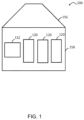
- FIG. 1 there is shown an embodiment illustrating a vehicle which may be any type of vehicle such as, for example, aircraft, spacecraft, space station, satellite, land vehicles and marine vehicles used while implementing the teachings herein.
- vehicle is hereinafter simply referred to as a spacecraft 100.
- teachings herein are not to be limited to only spacecraft.
- the spacecraft 100 is configured from multiple preconstructed assemblies such as assemblies 156, 158 shown in FIG. 1 .
- assemblies 156, 158 shown in FIG. 1 .
- the spacecraft 100 is depicted as having only the two assemblies 156, 158, any number of assemblies may be utilized to configure a vehicle such as the spacecraft 100.
- Each of the assemblies is manufactured to include one or more interior systems.
- the assembly 158 includes interior systems 120.
- each assembly may have any number of interior systems 120.
- An interior system 120 can be, for example, a life support system, air revitalization system, pressure control system, and the like.
- Each system may include, for example, various subsystems depending on the intended function such as controllers, processors, fans, actuators, valves, regulators, motors, generators, heat exchangers, carbon dioxide removal systems, trace contaminant control, smoke detectors and the like.
- the interior systems and subsystems may be hardened against radiation so that they may function and survive within a radiation environment.
- the spacecraft 100 includes a system control 132 for monitoring and managing the operation and behavior of the spacecraft 100 as well as the interior systems 120.
- the system control 132 receives telemetry data from the spacecraft 100 which it uses to monitor the spacecraft's health.
- the telemetry data contains sampled data to provide information about its internal systems 120.
- the system control 132 is a computerized system similar to a general-purpose computing system that is radiation hardened and that is allocated with mission and internal system requirements which define the system control's operational modes and states.
- FIG. 3 illustrates an exemplary embodiment of the physical components (i.e., hardware) of the control system 132.
- FIG. 2 depicts a field programmable gate array (FPGA) based diagnostic circuitry for a space environment for implementing one or more embodiments of the teachings herein.
- An assembly 158 of a vehicle for example the spacecraft 100, includes the FPGA 210.
- the FPGA 210 includes programable circuity for providing one or more controllers 220.
- Each controller 220 is configured to control at least one internal system 120 such as, for example, the life support system within the space craft 100.
- the data acquired from the internal system 120 is highspeed data including real-time data.
- the highspeed data received by the FPGA 210 is at a rate that exceeds a data rate of the system control 132 of the spacecraft 100.
- both the FPGA 210 and an electric motor 230 are embedded within the assembly 158.
- the controller 220 controls the electric motor 230 for use with an HED pump of an internal system 120.
- the motor 230 is driven by commands issued by a drive stage 236.
- the controller 220 includes a logic analyzer in the form of hardware description programming language such as, for example, Very Highspeed Integrated Circuit (VHSIC) Hardware Description Language (VHDL) for performing analytical performance modeling of the controller 220.
- VHSIC Very Highspeed Integrated Circuit
- VHDL Hardware Description Language
- the VHDL 226 provides a diagnostic interface 228 that utilizes the highspeed data to model the performance of the controller 220 to investigate potential failure modes and determine possible effects while the controller 220 drives the operation of the function of the internal system 120.
- the diagnostic interface 228 allows external access to operational parameters of the radiation hardened subsystem.
- the controller 220 is interchangeable with another different controller 220, of the same FPGA 210 or some other FPGA of the same assembly 158, in order to control the same internal system 120 of the spacecraft 100.
- the modeling performance is then performed via the different controller 220.
- the controller 220 can be identified via the diagnostic interface 228 and then the identity of the controller 220 and the highspeed data from the controller 220, at a suitable data rate for the control system 132, can be provided to the system control 132.
- the FPGA 210 Upon a failure being detected, for example a failure detected by the system control 132 of the spacecraft 100, the FPGA 210 receives an indication of the failure from the system control 132 of the spacecraft 100. Receipt of the indication of the failure then initiates the performance modeling by the VHDL 226. The FPGA 210 then utilizes the performance modeling of the controller 220 by the VHDL 226 to ascertain whether or not the controller 220 is the source of the indicated failure. In one or more embodiments, from within an environmentally hardened system, the highspeed output of the VHDL 226 includes ascertaining from the performance modeling of the controller 220 that the controller 220 is the source of the failure.
- the output of the VHDL 226 includes ascertaining from the performance modeling of the controller 220 that the controller 220 is not the source of the failure. In either case, ascertaining whether or not the controller 220 is the source of the failure precludes disassembly of the assembly158 in order to ascertain from the performance modeling whether or not the controller 220 is the source of the failure. In other words, utilizing the FPGA 210 with the VHDL 228 allows ascertaining whether or not the controller 220 is the source of the failure to be free from disassembly of the assembly 158 and the interior system 120 of the spacecraft 100.
- the output from the VHDL 226 also includes, for example, depending on the function of the interior system, the duty cycle of the motor, HED position, motor phase current, drive stage commands, motor speed, stall detection, and current limit density.
- the data is received and analyzed by the VHDL 226 to allow real-time external output for understanding detected failures and anomalies despite the controller 220 being embedded within an environmentally hardened system.
- the control system 132 includes at least one processing unit 302 and a system memory 304.
- the system memory 304 comprises, but is not limited to, volatile storage (e.g., random access memory), non-volatile storage (e.g., read-only memory), flash memory, or any combination of such memories.
- the system memory 304 includes an operating system 305 and one or more program modules 306 suitable for running software applications 318.
- the system memory 304 includes a diagnostic module 316 for providing diagnostic information via a diagnostic interface of the FPGA 210.
- the operating system 305 is suitable for controlling the operation of the control system 132.
- diagnostics module 316 can initiate via the FPGA 210 performance modeling of the functioning of one or more interior systems 140. Moreover, upon the diagnostics module 316 detecting a failure, the system control 132 can issue a notification to the FPGA 210 indicating the failure.
- control system 132 has additional features or functionality.
- the control system 132 includes additional data storage devices (removable and/or non-removable) such as, for example, magnetic disks, optical disks, or tape.
- additional storage is illustrated in FIG. 3 by a removable storage device 319 and a non-removable storage device 320.
- a number of program modules and data files are stored in the system memory 304. While executing on the processing unit 302, the program modules 306 (e.g., diagnostics module 316) perform processes including, but not limited to, one or more of the stages or steps of the method 400 illustrated in FIG. 4 . According to an aspect, other program modules are also used.
- the program modules 306 e.g., diagnostics module 316
- the program modules 306 perform processes including, but not limited to, one or more of the stages or steps of the method 400 illustrated in FIG. 4 .
- other program modules are also used.
- one or more embodiments may include a method 400 for diagnosing a failure detected by a system control managing a vehicle.
- the flow diagram of FIG. 4 illustrates the method 400 that includes process block 410 for receiving highspeed data at a FPGA embedded in an assembly of the vehicle, the FPGA comprising a controller and a digital diagnostic interface, the diagnostic interface configured for utilizing hardware description programming language for performance modeling of the controller, wherein the controller is configured to control at least one internal system of a plurality of internal systems within the vehicle.
- the method 400 also includes process block 420 for modeling performance of the controller via the hardware description programming language while the controller drives functioning of the at least one internal system.
- the method 400 includes process block 430 for receiving at the FPGA an indication of a failure from the system control of the vehicle and process block 440 for utilizing the performance modeling of the controller to ascertain whether or not the controller is a source of the failure.
- the method 400 may also include where receiving highspeed data includes receiving high speed data at a rate that exceeds a data rate of the system control of the vehicle.
- the method 400 may also include where receiving highspeed data includes receiving real-time data.
- the method 400 can include ascertaining from the performance modeling of the controller that the controller is not the source of the failure. Also, the method 400 can include precluding disassembly of the assembly in order to ascertain from the performance modeling of the controller whether or not the controller is the source of the failure and the controller controlling a motor of the at least one internal system within the assembly of the vehicle.
- the method 400 may also include the diagnostic interface providing to the system control identification of the controller and access to the highspeed data from the controller.
- the method 400 can include where the vehicle is a spacecraft and the internal systems within the spacecraft are hardened against a radiation environment and where at least one internal system of the assembly of the spacecraft is a life support system.
- the method 400 may also include where the hardware description programming language is VHDL.
- the method 400 can also include interchanging the controller with another different controller configured to control the same at least one internal system of the vehicle.
Landscapes
- Engineering & Computer Science (AREA)
- Theoretical Computer Science (AREA)
- Physics & Mathematics (AREA)
- General Physics & Mathematics (AREA)
- General Engineering & Computer Science (AREA)
- Software Systems (AREA)
- Quality & Reliability (AREA)
- Automation & Control Theory (AREA)
- Computing Systems (AREA)
- Life Sciences & Earth Sciences (AREA)
- Computer Hardware Design (AREA)
- Testing And Monitoring For Control Systems (AREA)
- Bioinformatics & Computational Biology (AREA)
- Bioinformatics & Cheminformatics (AREA)
- Mathematical Physics (AREA)
- Evolutionary Biology (AREA)
- Health & Medical Sciences (AREA)
- Environmental & Geological Engineering (AREA)
- Environmental Sciences (AREA)
- General Health & Medical Sciences (AREA)
- Toxicology (AREA)
- Remote Sensing (AREA)
- Aviation & Aerospace Engineering (AREA)
- Biodiversity & Conservation Biology (AREA)
- Human Computer Interaction (AREA)
- Transportation (AREA)
- Mechanical Engineering (AREA)
Description
- The invention relates generally to controllers, and more particularly, to a highspeed interface for diagnosing whether the controllers are the source of detected failures.
- Vehicles such as aircraft and spacecraft each incorporate numerous different systems that require testing and troubleshooting during manufacture and assembly. Because of economy of space, these systems are often deeply embedded within various assemblies that form the vehicle. For example, because access is limited due to the spacecraft's design, the system components are difficult to access when failures occur during testing. Moreover, the motors used in spacecraft assemblies are hardened in order to survive in a radiation environment. These motors that are deeply embedded within a vehicle assembly are the usual suspects when failures occur. Also, during system operation and testing, higher system constraints typically preclude various motor parameters from being included in telemetry at a rate that allows system anomalies to be sufficiently understood. Furthermore, disassembly of a vehicle assembly in order to remove a component creates cost and scheduling issues. Removal of a controller or its motor requires testing be repeated. What is needed, without interfering with system operations, is external access to all motor operational parameters including rapid collection of real time data that allows detailed analysis of motor operations. A motor controller interface is described in ODAVIC M et al: 'Real-time fault diagnostics for a permanent magnet synchronous motor drive for aerospace applications', ENERGY CONVERSION CONGRESS AND EXPOSITION (ECCE), 2010 IEEE, 12 September 2010 pages 3044-3049, ISBN: 978-1-4244-5286-6.
- According to one aspect, a method for diagnosing a failure detected by a system control managing a vehicle is provided as defined by
claim 1. - According to another aspect, a FPGA is provided as defined by claim 9.
- A diagnostic interface for diagnosing a source of a failure is also described. The diagnostic interface is configured from a FPGA embedded in an assembly of a vehicle. The FPGA accesses real-time data from a controller and utilizes the real-time data with VHDL for performance modeling of the controller. The diagnostic interface utilizes the performance modeling of the controller to ascertain whether or not the controller is the source of the failure.
- Additional features and advantages are realized through the techniques of the invention. Other embodiments and aspects of the invention are described in detail herein and are considered a part of the claimed invention. For a better understanding of the invention with the advantages and the features, refer to the description and to the drawings.
- The subject matter which is regarded as the invention is particularly pointed out and distinctly claimed in the claims at the conclusion of the specification. The foregoing and other features, and advantages of the invention are apparent from the following detailed description taken in conjunction with the accompanying drawings, in which:
-
FIG. 1 depicts an exemplary embodiment of a spacecraft having a system control and a plurality of interior systems for a space environment according to one or more embodiments of the present disclosure; -
FIG. 2 depicts a field programmable gate array (FPGA) based diagnostic circuitry for a space environment according to one or more embodiments of the present invention; -
FIG. 3 depicts a block diagram illustrating an exemplary control system that may be utilized to implement one or more embodiments of the present invention; and -
FIG. 4 is a flow diagram illustrating a method of diagnosing a failure detected by a system control managing a vehicle according to one or more embodiments of the present invention. - The diagrams depicted herein are illustrative. There can be many variations to the diagram or the operations described therein without departing from the invention as defined by the claims. For instance, the actions can be performed in a differing order or actions can be added, deleted or modified. Also, the term "coupled" and variations thereof describes having a communications path between two elements and does not imply a direct connection between the elements with no intervening elements/connections between them. All of these variations are considered a part of the specification.
- In the accompanying figures and following detailed description of the disclosed embodiments, the various elements illustrated in the figures are provided with two or three digit reference numbers. With minor exceptions, the leftmost digit(s) of each reference number correspond to the figure in which its element is first illustrated.
- Various embodiments of the invention are described herein with reference to the related drawings. Various connections and positional relationships (e.g., over, below, adjacent, etc.) are set forth between elements in the following description and in the drawings. These connections and/or positional relationships, unless specified otherwise, can be direct or indirect, and the present invention is not intended to be limiting in this respect. Accordingly, a coupling of entities can refer to either a direct or an indirect coupling, and a positional relationship between entities can be a direct or indirect positional relationship. Moreover, the various tasks and process steps described herein can be incorporated into a more comprehensive procedure or process having additional steps or functionality not described in detail herein.
- The following definitions and abbreviations are to be used for the interpretation of the claims and the specification. As used herein, the terms "comprises," "comprising," "includes," "including," "has," "having," "contains" or "containing," or any other variation thereof, are intended to cover a non-exclusive inclusion. For example, a composition, a mixture, process, method, article, or apparatus that comprises a list of elements is not necessarily limited to only those elements but can include other elements not expressly listed or inherent to such composition, mixture, process, method, article, or apparatus.
- Additionally, the term "exemplary" is used herein to mean "serving as an example, instance or illustration." Any embodiment or design described herein as "exemplary" is not necessarily to be construed as preferred or advantageous over other embodiments or designs. The terms "at least one" and "one or more" may be understood to include any integer number greater than or equal to one, i.e. one, two, three, four, etc. The terms "a plurality" may be understood to include any integer number greater than or equal to two, i.e. two, three, four, five, etc. The term "connection" may include both an indirect "connection" and a direct "connection."
- The terms "about," "substantially," "approximately," and variations thereof, are intended to include the degree of error associated with measurement of the particular quantity based upon the equipment available at the time of filing the application. For example, "about" can include a range of ± 8% or 5%, or 2% of a given value.
- For the sake of brevity, conventional techniques related to making and using aspects of the invention may or may not be described in detail herein. Accordingly, in the interest of brevity, many conventional implementation details are only mentioned briefly herein or are omitted entirely without providing the well-known system and/or process details.
- Referring to
FIG. 1 , there is shown an embodiment illustrating a vehicle which may be any type of vehicle such as, for example, aircraft, spacecraft, space station, satellite, land vehicles and marine vehicles used while implementing the teachings herein. For explanation purposes, the vehicle is hereinafter simply referred to as aspacecraft 100. However, the teachings herein are not to be limited to only spacecraft. - In one or more embodiments, the
spacecraft 100 is configured from multiple preconstructed assemblies such asassemblies FIG. 1 . Although thespacecraft 100 is depicted as having only the twoassemblies spacecraft 100. Each of the assemblies is manufactured to include one or more interior systems. For example, inFIG. 1 theassembly 158 includesinterior systems 120. However, each assembly may have any number ofinterior systems 120. Aninterior system 120 can be, for example, a life support system, air revitalization system, pressure control system, and the like. Each system may include, for example, various subsystems depending on the intended function such as controllers, processors, fans, actuators, valves, regulators, motors, generators, heat exchangers, carbon dioxide removal systems, trace contaminant control, smoke detectors and the like. Depending on the type of vehicle, such as a spacecraft or space station, the interior systems and subsystems may be hardened against radiation so that they may function and survive within a radiation environment. - Still referring to
FIG. 1 , thespacecraft 100 includes asystem control 132 for monitoring and managing the operation and behavior of thespacecraft 100 as well as theinterior systems 120. In particular, thesystem control 132 receives telemetry data from thespacecraft 100 which it uses to monitor the spacecraft's health. The telemetry data contains sampled data to provide information about itsinternal systems 120. Thesystem control 132 is a computerized system similar to a general-purpose computing system that is radiation hardened and that is allocated with mission and internal system requirements which define the system control's operational modes and states.FIG. 3 illustrates an exemplary embodiment of the physical components (i.e., hardware) of thecontrol system 132. -
FIG. 2 depicts a field programmable gate array (FPGA) based diagnostic circuitry for a space environment for implementing one or more embodiments of the teachings herein. Anassembly 158 of a vehicle, for example thespacecraft 100, includes theFPGA 210. TheFPGA 210 includes programable circuity for providing one ormore controllers 220. Eachcontroller 220 is configured to control at least oneinternal system 120 such as, for example, the life support system within thespace craft 100. Because of theFPGA 210, the data acquired from theinternal system 120 is highspeed data including real-time data. In one or more embodiments, the highspeed data received by theFPGA 210 is at a rate that exceeds a data rate of thesystem control 132 of thespacecraft 100. - In the example of
FIG. 2 , both theFPGA 210 and anelectric motor 230 are embedded within theassembly 158. Thecontroller 220 controls theelectric motor 230 for use with an HED pump of aninternal system 120. In one or more embodiments, themotor 230 is driven by commands issued by adrive stage 236. Thecontroller 220 includes a logic analyzer in the form of hardware description programming language such as, for example, Very Highspeed Integrated Circuit (VHSIC) Hardware Description Language (VHDL) for performing analytical performance modeling of thecontroller 220. TheVHDL 226 provides adiagnostic interface 228 that utilizes the highspeed data to model the performance of thecontroller 220 to investigate potential failure modes and determine possible effects while thecontroller 220 drives the operation of the function of theinternal system 120. In one or more embodiments, despite theinternal system 120 and the corresponding one or more subsystems being radiation hardened, thediagnostic interface 228 allows external access to operational parameters of the radiation hardened subsystem. - In one or more embodiments, the
controller 220 is interchangeable with anotherdifferent controller 220, of thesame FPGA 210 or some other FPGA of thesame assembly 158, in order to control the sameinternal system 120 of thespacecraft 100. In such case, the modeling performance is then performed via thedifferent controller 220. Thecontroller 220 can be identified via thediagnostic interface 228 and then the identity of thecontroller 220 and the highspeed data from thecontroller 220, at a suitable data rate for thecontrol system 132, can be provided to thesystem control 132. - Upon a failure being detected, for example a failure detected by the
system control 132 of thespacecraft 100, theFPGA 210 receives an indication of the failure from thesystem control 132 of thespacecraft 100. Receipt of the indication of the failure then initiates the performance modeling by theVHDL 226. TheFPGA 210 then utilizes the performance modeling of thecontroller 220 by theVHDL 226 to ascertain whether or not thecontroller 220 is the source of the indicated failure. In one or more embodiments, from within an environmentally hardened system, the highspeed output of theVHDL 226 includes ascertaining from the performance modeling of thecontroller 220 that thecontroller 220 is the source of the failure. Also, in one or more other embodiments, the output of theVHDL 226 includes ascertaining from the performance modeling of thecontroller 220 that thecontroller 220 is not the source of the failure. In either case, ascertaining whether or not thecontroller 220 is the source of the failure precludes disassembly of the assembly158 in order to ascertain from the performance modeling whether or not thecontroller 220 is the source of the failure. In other words, utilizing theFPGA 210 with theVHDL 228 allows ascertaining whether or not thecontroller 220 is the source of the failure to be free from disassembly of theassembly 158 and theinterior system 120 of thespacecraft 100. From within an environmentally hardened system, the output from theVHDL 226 also includes, for example, depending on the function of the interior system, the duty cycle of the motor, HED position, motor phase current, drive stage commands, motor speed, stall detection, and current limit density. The data is received and analyzed by theVHDL 226 to allow real-time external output for understanding detected failures and anomalies despite thecontroller 220 being embedded within an environmentally hardened system. - Referring to
FIG. 3 , an embodiment illustrating physical components of thecontrol system 132 is shown. In a basic configuration, thecontrol system 132 includes at least oneprocessing unit 302 and asystem memory 304. According to an aspect, depending on the configuration and type ofcontrol system 132, thesystem memory 304 comprises, but is not limited to, volatile storage (e.g., random access memory), non-volatile storage (e.g., read-only memory), flash memory, or any combination of such memories. According to an aspect, thesystem memory 304 includes anoperating system 305 and one ormore program modules 306 suitable for runningsoftware applications 318. According to an aspect, thesystem memory 304 includes adiagnostic module 316 for providing diagnostic information via a diagnostic interface of theFPGA 210. Theoperating system 305, for example, is suitable for controlling the operation of thecontrol system 132. In one or more embodiments,diagnostics module 316 can initiate via theFPGA 210 performance modeling of the functioning of one or more interior systems 140. Moreover, upon thediagnostics module 316 detecting a failure, thesystem control 132 can issue a notification to theFPGA 210 indicating the failure. - Furthermore, aspects are practiced in conjunction with a graphics library, other operating systems, or any other application program, and is not limited to any particular application or system. This basic configuration is illustrated in
FIG. 3 by those components within a dashedline 308. According to an aspect, thecontrol system 132 has additional features or functionality. For example, according to an aspect, thecontrol system 132 includes additional data storage devices (removable and/or non-removable) such as, for example, magnetic disks, optical disks, or tape. Such additional storage is illustrated inFIG. 3 by aremovable storage device 319 and anon-removable storage device 320. - As stated above, according to an aspect, a number of program modules and data files are stored in the
system memory 304. While executing on theprocessing unit 302, the program modules 306 (e.g., diagnostics module 316) perform processes including, but not limited to, one or more of the stages or steps of themethod 400 illustrated inFIG. 4 . According to an aspect, other program modules are also used. - According to an aspect, the
control system 132 has one or more input device(s) 322 such as a keyboard, a mouse, a pen, a sound input device, a touch input device, etc. In one or more embodiments, the input device may be a recorder receiving a video feed from one or more video cameras. The output device(s) 324 such as a display, speakers, a printer, etc. are also included according to an aspect. The aforementioned devices are examples and others may be used. According to an aspect, thecontrol system 132 includes one ormore communication connections 326 allowing communications with ground control and other computing devices. Examples ofsuitable communication connections 326 include, but are not limited to, radio frequency (RF) transmitter, receiver, and/or transceiver circuitry; universal serial bus (USB), parallel, and/or serial ports. - Turning to
FIG. 4 , one or more embodiments may include amethod 400 for diagnosing a failure detected by a system control managing a vehicle. The flow diagram ofFIG. 4 illustrates themethod 400 that includes process block 410 for receiving highspeed data at a FPGA embedded in an assembly of the vehicle, the FPGA comprising a controller and a digital diagnostic interface, the diagnostic interface configured for utilizing hardware description programming language for performance modeling of the controller, wherein the controller is configured to control at least one internal system of a plurality of internal systems within the vehicle. Themethod 400 also includes process block 420 for modeling performance of the controller via the hardware description programming language while the controller drives functioning of the at least one internal system. Also, themethod 400 includes process block 430 for receiving at the FPGA an indication of a failure from the system control of the vehicle and process block 440 for utilizing the performance modeling of the controller to ascertain whether or not the controller is a source of the failure. - In one or more embodiments, the
method 400 may also include where receiving highspeed data includes receiving high speed data at a rate that exceeds a data rate of the system control of the vehicle. Themethod 400 may also include where receiving highspeed data includes receiving real-time data. Themethod 400 can include ascertaining from the performance modeling of the controller that the controller is not the source of the failure. Also, themethod 400 can include precluding disassembly of the assembly in order to ascertain from the performance modeling of the controller whether or not the controller is the source of the failure and the controller controlling a motor of the at least one internal system within the assembly of the vehicle. Themethod 400 may also include the diagnostic interface providing to the system control identification of the controller and access to the highspeed data from the controller. Themethod 400 can include where the vehicle is a spacecraft and the internal systems within the spacecraft are hardened against a radiation environment and where at least one internal system of the assembly of the spacecraft is a life support system. Themethod 400 may also include where the hardware description programming language is VHDL. Themethod 400 can also include interchanging the controller with another different controller configured to control the same at least one internal system of the vehicle. - The descriptions of the various embodiments of the present invention have been presented for purposes of illustration, but are not intended to be exhaustive or limited to the embodiments disclosed. Many modifications and variations will be apparent to those of ordinary skill in the art without departing from the scope of the invention as defined by the claims. The terminology used herein was chosen to best explain the principles of the embodiments, the practical application or technical improvement over technologies found in the marketplace, or to enable others of ordinary skill in the art to understand the embodiments disclosed herein.
Claims (13)
- A method for diagnosing a failure detected by a system control (132) managing a vehicle, the method comprising:receiving (410) data at a field programmable gate array, FPGA (210), embedded in an assembly of the vehicle, the FPGA comprising a controller (220), wherein the FPGA (210) comprises VHDL diagnostic code (226) for performance modeling of the controller, wherein the controller is configured to control at least one internal system of a plurality of internal systems within the vehicle;modeling (420) performance of the controller via the VHDL diagnostic code while the controller drives functioning of the at least one internal system;the method being further characterized by the steps of:receiving (430) at the FPGA an indication of a failure from the system control of the vehicle (132); andutilizing (440) the performance modeling of the controller to ascertain whether or not the controller is a source of the failure.
- The method of claim 1, wherein receiving data comprises receiving high speed data at a rate that exceeds a data rate of the system control of the vehicle, or wherein receiving data comprises receiving real-time data.
- The method of claim 1 or 2, further comprising the controller (132) controlling a motor (230) of the at least one internal system within the assembly of the vehicle.
- The method of any preceding claim, wherein the controller provides to the system control identification of the controller and access to the highspeed data from the controller.
- The method of any preceding claim, wherein the at least one internal system of the assembly of the vehicle is a life support system for the vehicle.
- The method of any preceding claim, wherein the hardware description programming language is Very Highspeed Integrated Circuit, VHSIC, Hardware Description Language, VHDL.
- The method of any preceding claim, further comprising interchanging the controller with another different controller configured to control the same at least one internal system of the vehicle.
- The method of any preceding claim, wherein the vehicle is a spacecraft (100) and the internal systems within the spacecraft are hardened against a radiation environment.
- A field programable gate array, FPGA(210), comprising a controller (220), wherein the FPGA comprises VHDL diagnostic code (226), for performance modeling of the controller, wherein the controller is configured to control an internal system of a plurality of internal systems within a spacecraft (100),
the FPGA being configured to use the VHDL diagnostic code for modeling (420) performance of the controller while the controller drives functioning of the internal system of the spacecraft, further characterized by:the FPGA being configured for receiving (430) an indication of a failure from a system control (132) of the spacecraft,and the FPGA being configured for utilizing (440) the performance modeling of the controller to ascertain whether or not the controller is a source of the failure. - The FPGA of claim 9, wherein the FPGA is embedded within an assembly of the spacecraft.
- The FPGA of claim 9 or 10, wherein the FPGA is configured to receive real-time data from the system of the spacecraft.
- The FPGA of claim 9, 10 or 11, wherein the FPGA controls functioning of a motor (230) of the internal system of the spacecraft, and wherein the FPGA and the motor are embedded within an assembly of the spacecraft.
- The FPGA of any of claims 9 to 12, comprising one or more other controllers and wherein the controller controlling the interior system of the spacecraft is interchangeable with at least one of the one or more other controllers, and the diagnostic interface modeling performance of the at least one other controller.
Applications Claiming Priority (1)
| Application Number | Priority Date | Filing Date | Title |
|---|---|---|---|
| US16/365,221 US11199585B2 (en) | 2019-03-26 | 2019-03-26 | Highspeed data interface for distributed system motor controllers |
Publications (2)
| Publication Number | Publication Date |
|---|---|
| EP3716068A1 EP3716068A1 (en) | 2020-09-30 |
| EP3716068B1 true EP3716068B1 (en) | 2025-06-25 |
Family
ID=68762364
Family Applications (1)
| Application Number | Title | Priority Date | Filing Date |
|---|---|---|---|
| EP19210085.7A Active EP3716068B1 (en) | 2019-03-26 | 2019-11-19 | Highspeed data interface for distributed system motor controllers |
Country Status (2)
| Country | Link |
|---|---|
| US (1) | US11199585B2 (en) |
| EP (1) | EP3716068B1 (en) |
Family Cites Families (7)
| Publication number | Priority date | Publication date | Assignee | Title |
|---|---|---|---|---|
| US6996443B2 (en) * | 2002-01-11 | 2006-02-07 | Bae Systems Information And Electronic Systems Integration Inc. | Reconfigurable digital processing system for space |
| US8294396B2 (en) | 2009-07-13 | 2012-10-23 | Hamilton Sundstrand Space Systems International, Inc. | Compact FPGA-based digital motor controller |
| US9444376B2 (en) | 2013-02-22 | 2016-09-13 | Hamilton Sundstrand Corporation | Variable link sensorless brushless direct current motor controller for space and hardened applications |
| US10336472B2 (en) | 2014-10-15 | 2019-07-02 | The Boeing Company | Motor health management apparatus and method |
| US9836221B1 (en) | 2014-11-10 | 2017-12-05 | Ball Aerospace & Technologies Corp. | Configurable high speed FPGA scan mechanism controller |
| US10289092B2 (en) * | 2016-01-14 | 2019-05-14 | Hamilton Sundstrand Space Systems International Inc. | Digital motor controller stability analysis tool |
| US10521295B2 (en) * | 2016-06-23 | 2019-12-31 | Triad National Security, Llc | Low cost, hardened single board computer for command and data handling |
-
2019
- 2019-03-26 US US16/365,221 patent/US11199585B2/en active Active
- 2019-11-19 EP EP19210085.7A patent/EP3716068B1/en active Active
Also Published As
| Publication number | Publication date |
|---|---|
| US20200312061A1 (en) | 2020-10-01 |
| EP3716068A1 (en) | 2020-09-30 |
| US11199585B2 (en) | 2021-12-14 |
Similar Documents
| Publication | Publication Date | Title |
|---|---|---|
| US7081729B2 (en) | Variable-structure diagnostics approach achieving optimized low-frequency data sampling for EMA motoring subsystem | |
| US5919267A (en) | Neural network fault diagnostics systems and related method | |
| EP3379436A1 (en) | Method and apparatus for testing design of satellite wiring harness and signal processing units | |
| EP2808846A1 (en) | Device and method for detecting faults in electronic systems | |
| Brown et al. | Prognostics enhanced reconfigurable control of electro-mechanical actuators | |
| EP3440635B1 (en) | Systems and methods to determine maintenance-focused aircraft data recording frame configurations | |
| EP3716640B1 (en) | Shared resistive sensor measurment with fpga based collision avoidance protection | |
| CN107483283B (en) | Communication reliability test method and device | |
| US10120702B2 (en) | Platform simulation for management controller development projects | |
| Brown et al. | Particle filter based anomaly detection for aircraft actuator systems | |
| Fernández et al. | Telemetry anomaly detection system using machine learning to streamline mission operations | |
| US11199585B2 (en) | Highspeed data interface for distributed system motor controllers | |
| Vohnout et al. | Electronic prognostics system implementation on power actuator components | |
| EP3715968B1 (en) | Reconfigurable stand alone distributed system motor controllers | |
| Kitts | Managing space system anomalies using first principles reasoning | |
| US9766871B2 (en) | Method and apparatus for operating a processing and/or production installation | |
| Barua et al. | On the fault diagnosis and failure analysis in the satellite attitude control subsystem | |
| Djurdjanovic et al. | Immune systems inspired approach to anomaly detection and fault diagnosis for engines | |
| Bock et al. | On false alarm mitigation | |
| Manor-Chapman et al. | The InSight APSS Data Return Anomaly: Development of an Automated Detection and Response Method | |
| Bukov et al. | Logical pair monitoring that accounts for the grey zone | |
| Park et al. | BEAM: technology for autonomous vehicle health monitoring | |
| Marcia | Metadata of the chapter that will be visualized in SpringerLink | |
| KR20260026810A (en) | Fault diagnosis apparatus and method using bayesian based deep learning diagnosis model | |
| Su et al. | Prognostics framework-update II |
Legal Events
| Date | Code | Title | Description |
|---|---|---|---|
| PUAI | Public reference made under article 153(3) epc to a published international application that has entered the european phase |
Free format text: ORIGINAL CODE: 0009012 |
|
| STAA | Information on the status of an ep patent application or granted ep patent |
Free format text: STATUS: THE APPLICATION HAS BEEN PUBLISHED |
|
| AK | Designated contracting states |
Kind code of ref document: A1 Designated state(s): AL AT BE BG CH CY CZ DE DK EE ES FI FR GB GR HR HU IE IS IT LI LT LU LV MC MK MT NL NO PL PT RO RS SE SI SK SM TR |
|
| AX | Request for extension of the european patent |
Extension state: BA ME |
|
| STAA | Information on the status of an ep patent application or granted ep patent |
Free format text: STATUS: REQUEST FOR EXAMINATION WAS MADE |
|
| 17P | Request for examination filed |
Effective date: 20210330 |
|
| RBV | Designated contracting states (corrected) |
Designated state(s): AL AT BE BG CH CY CZ DE DK EE ES FI FR GB GR HR HU IE IS IT LI LT LU LV MC MK MT NL NO PL PT RO RS SE SI SK SM TR |
|
| STAA | Information on the status of an ep patent application or granted ep patent |
Free format text: STATUS: EXAMINATION IS IN PROGRESS |
|
| 17Q | First examination report despatched |
Effective date: 20220520 |
|
| REG | Reference to a national code |
Ref country code: DE Ref legal event code: R079 Free format text: PREVIOUS MAIN CLASS: G06F0011070000 Ipc: G05B0019042000 Ref country code: DE Ref legal event code: R079 Ref document number: 602019071485 Country of ref document: DE Free format text: PREVIOUS MAIN CLASS: G06F0011070000 Ipc: G05B0019042000 |
|
| GRAP | Despatch of communication of intention to grant a patent |
Free format text: ORIGINAL CODE: EPIDOSNIGR1 |
|
| STAA | Information on the status of an ep patent application or granted ep patent |
Free format text: STATUS: GRANT OF PATENT IS INTENDED |
|
| RIC1 | Information provided on ipc code assigned before grant |
Ipc: G06F 11/34 20060101ALI20250110BHEP Ipc: G06F 11/30 20060101ALI20250110BHEP Ipc: G06F 11/07 20060101ALI20250110BHEP Ipc: B64G 1/46 20060101ALI20250110BHEP Ipc: G05B 19/042 20060101AFI20250110BHEP |
|
| INTG | Intention to grant announced |
Effective date: 20250128 |
|
| GRAS | Grant fee paid |
Free format text: ORIGINAL CODE: EPIDOSNIGR3 |
|
| GRAA | (expected) grant |
Free format text: ORIGINAL CODE: 0009210 |
|
| STAA | Information on the status of an ep patent application or granted ep patent |
Free format text: STATUS: THE PATENT HAS BEEN GRANTED |
|
| AK | Designated contracting states |
Kind code of ref document: B1 Designated state(s): AL AT BE BG CH CY CZ DE DK EE ES FI FR GB GR HR HU IE IS IT LI LT LU LV MC MK MT NL NO PL PT RO RS SE SI SK SM TR |
|
| REG | Reference to a national code |
Ref country code: GB Ref legal event code: FG4D |
|
| REG | Reference to a national code |
Ref country code: CH Ref legal event code: EP |
|
| REG | Reference to a national code |
Ref country code: CH Ref legal event code: EP |
|
| REG | Reference to a national code |
Ref country code: IE Ref legal event code: FG4D |
|
| REG | Reference to a national code |
Ref country code: DE Ref legal event code: R096 Ref document number: 602019071485 Country of ref document: DE |
|
| PG25 | Lapsed in a contracting state [announced via postgrant information from national office to epo] |
Ref country code: FI Free format text: LAPSE BECAUSE OF FAILURE TO SUBMIT A TRANSLATION OF THE DESCRIPTION OR TO PAY THE FEE WITHIN THE PRESCRIBED TIME-LIMIT Effective date: 20250625 |
|
| REG | Reference to a national code |
Ref country code: LT Ref legal event code: MG9D |
|
| PG25 | Lapsed in a contracting state [announced via postgrant information from national office to epo] |
Ref country code: NO Free format text: LAPSE BECAUSE OF FAILURE TO SUBMIT A TRANSLATION OF THE DESCRIPTION OR TO PAY THE FEE WITHIN THE PRESCRIBED TIME-LIMIT Effective date: 20250925 Ref country code: GR Free format text: LAPSE BECAUSE OF FAILURE TO SUBMIT A TRANSLATION OF THE DESCRIPTION OR TO PAY THE FEE WITHIN THE PRESCRIBED TIME-LIMIT Effective date: 20250926 |
|
| PG25 | Lapsed in a contracting state [announced via postgrant information from national office to epo] |
Ref country code: BG Free format text: LAPSE BECAUSE OF FAILURE TO SUBMIT A TRANSLATION OF THE DESCRIPTION OR TO PAY THE FEE WITHIN THE PRESCRIBED TIME-LIMIT Effective date: 20250625 |
|
| PG25 | Lapsed in a contracting state [announced via postgrant information from national office to epo] |
Ref country code: HR Free format text: LAPSE BECAUSE OF FAILURE TO SUBMIT A TRANSLATION OF THE DESCRIPTION OR TO PAY THE FEE WITHIN THE PRESCRIBED TIME-LIMIT Effective date: 20250625 |
|
| PG25 | Lapsed in a contracting state [announced via postgrant information from national office to epo] |
Ref country code: RS Free format text: LAPSE BECAUSE OF FAILURE TO SUBMIT A TRANSLATION OF THE DESCRIPTION OR TO PAY THE FEE WITHIN THE PRESCRIBED TIME-LIMIT Effective date: 20250925 |
|
| PG25 | Lapsed in a contracting state [announced via postgrant information from national office to epo] |
Ref country code: LV Free format text: LAPSE BECAUSE OF FAILURE TO SUBMIT A TRANSLATION OF THE DESCRIPTION OR TO PAY THE FEE WITHIN THE PRESCRIBED TIME-LIMIT Effective date: 20250625 |
|
| REG | Reference to a national code |
Ref country code: NL Ref legal event code: MP Effective date: 20250625 |
|
| PG25 | Lapsed in a contracting state [announced via postgrant information from national office to epo] |
Ref country code: NL Free format text: LAPSE BECAUSE OF FAILURE TO SUBMIT A TRANSLATION OF THE DESCRIPTION OR TO PAY THE FEE WITHIN THE PRESCRIBED TIME-LIMIT Effective date: 20250625 |
|
| PG25 | Lapsed in a contracting state [announced via postgrant information from national office to epo] |
Ref country code: PT Free format text: LAPSE BECAUSE OF FAILURE TO SUBMIT A TRANSLATION OF THE DESCRIPTION OR TO PAY THE FEE WITHIN THE PRESCRIBED TIME-LIMIT Effective date: 20251027 |
|
| REG | Reference to a national code |
Ref country code: AT Ref legal event code: MK05 Ref document number: 1807099 Country of ref document: AT Kind code of ref document: T Effective date: 20250625 |
|
| PG25 | Lapsed in a contracting state [announced via postgrant information from national office to epo] |
Ref country code: IS Free format text: LAPSE BECAUSE OF FAILURE TO SUBMIT A TRANSLATION OF THE DESCRIPTION OR TO PAY THE FEE WITHIN THE PRESCRIBED TIME-LIMIT Effective date: 20251025 |
|
| PGFP | Annual fee paid to national office [announced via postgrant information from national office to epo] |
Ref country code: DE Payment date: 20251022 Year of fee payment: 7 |
|
| PG25 | Lapsed in a contracting state [announced via postgrant information from national office to epo] |
Ref country code: AT Free format text: LAPSE BECAUSE OF FAILURE TO SUBMIT A TRANSLATION OF THE DESCRIPTION OR TO PAY THE FEE WITHIN THE PRESCRIBED TIME-LIMIT Effective date: 20250625 Ref country code: SM Free format text: LAPSE BECAUSE OF FAILURE TO SUBMIT A TRANSLATION OF THE DESCRIPTION OR TO PAY THE FEE WITHIN THE PRESCRIBED TIME-LIMIT Effective date: 20250625 |
|
| PGFP | Annual fee paid to national office [announced via postgrant information from national office to epo] |
Ref country code: IT Payment date: 20251022 Year of fee payment: 7 |
|
| PGFP | Annual fee paid to national office [announced via postgrant information from national office to epo] |
Ref country code: FR Payment date: 20251023 Year of fee payment: 7 |
|
| PG25 | Lapsed in a contracting state [announced via postgrant information from national office to epo] |
Ref country code: CZ Free format text: LAPSE BECAUSE OF FAILURE TO SUBMIT A TRANSLATION OF THE DESCRIPTION OR TO PAY THE FEE WITHIN THE PRESCRIBED TIME-LIMIT Effective date: 20250625 |
|
| PG25 | Lapsed in a contracting state [announced via postgrant information from national office to epo] |
Ref country code: PL Free format text: LAPSE BECAUSE OF FAILURE TO SUBMIT A TRANSLATION OF THE DESCRIPTION OR TO PAY THE FEE WITHIN THE PRESCRIBED TIME-LIMIT Effective date: 20250625 |
|
| PG25 | Lapsed in a contracting state [announced via postgrant information from national office to epo] |
Ref country code: EE Free format text: LAPSE BECAUSE OF FAILURE TO SUBMIT A TRANSLATION OF THE DESCRIPTION OR TO PAY THE FEE WITHIN THE PRESCRIBED TIME-LIMIT Effective date: 20250625 |
|
| PG25 | Lapsed in a contracting state [announced via postgrant information from national office to epo] |
Ref country code: SK Free format text: LAPSE BECAUSE OF FAILURE TO SUBMIT A TRANSLATION OF THE DESCRIPTION OR TO PAY THE FEE WITHIN THE PRESCRIBED TIME-LIMIT Effective date: 20250625 |
|
| PG25 | Lapsed in a contracting state [announced via postgrant information from national office to epo] |
Ref country code: ES Free format text: LAPSE BECAUSE OF FAILURE TO SUBMIT A TRANSLATION OF THE DESCRIPTION OR TO PAY THE FEE WITHIN THE PRESCRIBED TIME-LIMIT Effective date: 20250625 |
|
| PG25 | Lapsed in a contracting state [announced via postgrant information from national office to epo] |
Ref country code: RO Free format text: LAPSE BECAUSE OF FAILURE TO SUBMIT A TRANSLATION OF THE DESCRIPTION OR TO PAY THE FEE WITHIN THE PRESCRIBED TIME-LIMIT Effective date: 20250625 |
|
| PG25 | Lapsed in a contracting state [announced via postgrant information from national office to epo] |
Ref country code: DK Free format text: LAPSE BECAUSE OF FAILURE TO SUBMIT A TRANSLATION OF THE DESCRIPTION OR TO PAY THE FEE WITHIN THE PRESCRIBED TIME-LIMIT Effective date: 20250625 |
|
| PLBE | No opposition filed within time limit |
Free format text: ORIGINAL CODE: 0009261 |
|
| STAA | Information on the status of an ep patent application or granted ep patent |
Free format text: STATUS: NO OPPOSITION FILED WITHIN TIME LIMIT |
|
| REG | Reference to a national code |
Ref country code: CH Ref legal event code: L10 Free format text: ST27 STATUS EVENT CODE: U-0-0-L10-L00 (AS PROVIDED BY THE NATIONAL OFFICE) Effective date: 20260507 |