EP3715816A1 - Standoff fixture for laser inspection - Google Patents
Standoff fixture for laser inspection Download PDFInfo
- Publication number
- EP3715816A1 EP3715816A1 EP20166029.7A EP20166029A EP3715816A1 EP 3715816 A1 EP3715816 A1 EP 3715816A1 EP 20166029 A EP20166029 A EP 20166029A EP 3715816 A1 EP3715816 A1 EP 3715816A1
- Authority
- EP
- European Patent Office
- Prior art keywords
- legs
- standoff fixture
- standoff
- fixture
- measurement device
- Prior art date
- Legal status (The legal status is an assumption and is not a legal conclusion. Google has not performed a legal analysis and makes no representation as to the accuracy of the status listed.)
- Granted
Links
Images




Classifications
-
- G—PHYSICS
- G01—MEASURING; TESTING
- G01M—TESTING STATIC OR DYNAMIC BALANCE OF MACHINES OR STRUCTURES; TESTING OF STRUCTURES OR APPARATUS, NOT OTHERWISE PROVIDED FOR
- G01M15/00—Testing of engines
- G01M15/14—Testing gas-turbine engines or jet-propulsion engines
-
- G—PHYSICS
- G01—MEASURING; TESTING
- G01B—MEASURING LENGTH, THICKNESS OR SIMILAR LINEAR DIMENSIONS; MEASURING ANGLES; MEASURING AREAS; MEASURING IRREGULARITIES OF SURFACES OR CONTOURS
- G01B11/00—Measuring arrangements characterised by the use of optical techniques
- G01B11/26—Measuring arrangements characterised by the use of optical techniques for measuring angles or tapers; for testing the alignment of axes
-
- B—PERFORMING OPERATIONS; TRANSPORTING
- B33—ADDITIVE MANUFACTURING TECHNOLOGY
- B33Y—ADDITIVE MANUFACTURING, i.e. MANUFACTURING OF THREE-DIMENSIONAL [3D] OBJECTS BY ADDITIVE DEPOSITION, ADDITIVE AGGLOMERATION OR ADDITIVE LAYERING, e.g. BY 3D PRINTING, STEREOLITHOGRAPHY OR SELECTIVE LASER SINTERING
- B33Y50/00—Data acquisition or data processing for additive manufacturing
-
- B—PERFORMING OPERATIONS; TRANSPORTING
- B33—ADDITIVE MANUFACTURING TECHNOLOGY
- B33Y—ADDITIVE MANUFACTURING, i.e. MANUFACTURING OF THREE-DIMENSIONAL [3D] OBJECTS BY ADDITIVE DEPOSITION, ADDITIVE AGGLOMERATION OR ADDITIVE LAYERING, e.g. BY 3D PRINTING, STEREOLITHOGRAPHY OR SELECTIVE LASER SINTERING
- B33Y80/00—Products made by additive manufacturing
-
- G—PHYSICS
- G01—MEASURING; TESTING
- G01M—TESTING STATIC OR DYNAMIC BALANCE OF MACHINES OR STRUCTURES; TESTING OF STRUCTURES OR APPARATUS, NOT OTHERWISE PROVIDED FOR
- G01M11/00—Testing of optical apparatus; Testing structures by optical methods not otherwise provided for
- G01M11/08—Testing mechanical properties
- G01M11/081—Testing mechanical properties by using a contact-less detection method, i.e. with a camera
-
- G—PHYSICS
- G01—MEASURING; TESTING
- G01M—TESTING STATIC OR DYNAMIC BALANCE OF MACHINES OR STRUCTURES; TESTING OF STRUCTURES OR APPARATUS, NOT OTHERWISE PROVIDED FOR
- G01M13/00—Testing of machine parts
-
- G—PHYSICS
- G01—MEASURING; TESTING
- G01M—TESTING STATIC OR DYNAMIC BALANCE OF MACHINES OR STRUCTURES; TESTING OF STRUCTURES OR APPARATUS, NOT OTHERWISE PROVIDED FOR
- G01M5/00—Investigating the elasticity of structures, e.g. deflection of bridges or air-craft wings
- G01M5/0091—Investigating the elasticity of structures, e.g. deflection of bridges or air-craft wings by using electromagnetic excitation or detection
Definitions
- the present disclosure relates to inspection devices, methods, and systems, and more specifically to custom standoff fixtures for laser measurement devices, methods, and systems.
- Certain parts such as rotor elements of a gas turbine engine, are often inspected to ensure that such parts are sized correctly or otherwise have desired geometric specifications.
- conventional inspection methods generally involve creating a mold of the part and/or utilizing shadowgraph procedures to detect if features of the part are improperly sized/oriented or if the features of the part otherwise have an incorrect geometry.
- Such conventional inspection methods are often time-consuming and labor intensive.
- hand-held laser measurement devices may decrease overall time required for inspection, inspection results and inspection data from conventional hand-held laser measurement devices may suffer from inaccuracies due to varying users, inconsistencies of orientation/handling of the laser measurement device, and general lack of reproducibility.
- the present disclosure provides a method of inspecting a part.
- the method includes manufacturing a standoff fixture specific to the part, coupling the standoff fixture to a laser measurement device, engaging the standoff fixture with the part, and actuating the laser measurement device to detect a geometric specification of a feature of the part, according to various embodiments.
- the step of manufacturing the standoff fixture may include manufacturing the standoff fixture specific to the feature of the part.
- the standoff fixture comprises a plurality of legs
- manufacturing the standoff fixture comprises manufacturing the plurality of legs of the standoff fixture specific to the feature of the part.
- engaging the standoff fixture with the part comprises engaging the plurality of legs against the part.
- manufacturing the standoff fixture comprises using an additive manufacturing process.
- the part is a rotor disk of a gas turbine engine, and engaging the plurality of legs against the part comprises engaging a first leg of the plurality of legs against a web of the rotor disk. Further, engaging the plurality of legs against the part may include engaging a second leg of the plurality of legs against a flange of the rotor disk.
- feature of the part to be inspected is a chamfer of the flange of the rotor disk, and the geometric specification may be an angle and/or a dimension of the chamfer.
- the standoff fixture includes three legs such that engaging the standoff fixture with the part comprises engaging the three legs against the part.
- the geometric specification may include at least one of a radius, a mismatch, a chamfer angle, and a chamfer height.
- the standoff fixture for a laser measurement device.
- the standoff fixture includes an attachment portion configured to be coupled to the laser measurement device and a plurality of legs extending from the attachment portion, in accordance with various embodiments.
- the plurality of legs may be configured to engage with a part to be inspected, and the plurality of legs may be specific to the part to be inspected.
- each leg of the plurality of legs is oriented specific to the part to be inspected.
- the plurality of legs may comprise, respectively, a plurality of contact surfaces, with an orientation of each contact surface of the plurality of contact surfaces being specific to the part be inspected.
- the standoff fixture comprises a planar surface extending from the attachment portion to at least one leg of the plurality of legs such that the planar surface forms a portion of the attachment portion and a portion of the first leg.
- the planar surface may extend to a second leg of the plurality of legs such that the planar surface forms a portion of the second leg.
- the third leg may be oriented oblique to the planar surface.
- the inspection assembly may include a laser measurement device and a standoff fixture.
- the standoff fixture may be detachably coupleable to the laser measurement device.
- the present provides for standoff fixtures that are customized for a specific part (or at least a specific type of part) and that are configured to be coupled to a laser measurement device to facilitate accuracy, repeatability, and reproducibility of inspection procedures, according to various embodiments. While numerous details are included herein pertaining to standoff fixture that are used for inspecting components of a gas turbine engine (such as rotor disks), the standoff fixtures and the associated methods/systems may be used to inspect other components/parts.
- Gas turbine engine 20 may be a two-spool turbofan that generally incorporates a fan section 22, a compressor section 24, a combustor section 26 and a turbine section 28.
- fan section 22 can drive fluid (e.g., air) along a bypass flow-path B while compressor section 24 can drive fluid along a core flow-path C for compression and communication into combustor section 26 then expansion through turbine section 28.
- fluid e.g., air
- compressor section 24 can drive fluid along a core flow-path C for compression and communication into combustor section 26 then expansion through turbine section 28.
- Gas turbine engine 20 may generally comprise a low speed spool 30 and a high speed spool 32 mounted for rotation about an engine central longitudinal axis A-A' relative to an engine static structure 36 or engine case via several bearing systems 38, 38-1, and 38-2.
- Engine central longitudinal axis A-A' is oriented in the z direction (axial direction) on the provided xyz axis.
- the y direction on the provided xyz axis refers to a radial direction
- the x direction on the provided xyz axis refers to a circumferential direction.
- various bearing systems 38 at various locations may alternatively or additionally be provided, including for example, bearing system 38, bearing system 38-1, and bearing system 38-2.
- Low speed spool 30 may generally comprise an inner shaft 40 that interconnects a fan 42, a low pressure compressor 44 and a low pressure turbine 46.
- Inner shaft 40 may be connected to fan 42 through a geared architecture 48 that can drive fan 42 at a lower speed than low speed spool 30.
- Geared architecture 48 may comprise a gear assembly 60 enclosed within a gear housing 62.
- Gear assembly 60 couples inner shaft 40 to a rotating fan structure.
- High speed spool 32 may comprise an outer shaft 50 that interconnects a high pressure compressor 52 and high pressure turbine 54.
- a combustor 56 may be located between high pressure compressor 52 and high pressure turbine 54.
- the combustor section 26 may have an annular wall assembly having inner and outer shells that support respective inner and outer heat shielding liners.
- the heat shield liners may include a plurality of combustor panels that collectively define the annular combustion chamber of the combustor 56.
- An annular cooling cavity is defined between the respective shells and combustor panels for supplying cooling air. Impingement holes are located in the shell to supply the cooling air from an outer air plenum and into the annular cooling cavity.
- a mid-turbine frame 57 of engine static structure 36 may be located generally between high pressure turbine 54 and low pressure turbine 46.
- Mid-turbine frame 57 may support one or more bearing systems 38 in turbine section 28.
- Inner shaft 40 and outer shaft 50 may be concentric and rotate via bearing systems 38 about the engine central longitudinal axis A-A', which is collinear with their longitudinal axes.
- a "high pressure" compressor or turbine experiences a higher pressure than a corresponding "low pressure” compressor or turbine.
- the core airflow C may be compressed by low pressure compressor 44 then high pressure compressor 52, mixed and burned with fuel in combustor 56, then expanded over high pressure turbine 54 and low pressure turbine 46.
- Turbines 46, 54 rotationally drive the respective low speed spool 30 and high speed spool 32 in response to the expansion.
- geared architecture 48 may be an epicyclic gear train, such as a star gear system (sun gear in meshing engagement with a plurality of star gears supported by a carrier and in meshing engagement with a ring gear) or other gear system.
- Geared architecture 48 may have a gear reduction ratio of greater than about 2.3 and low pressure turbine 46 may have a pressure ratio that is greater than about five (5).
- the bypass ratio of gas turbine engine 20 is greater than about ten (10:1).
- the diameter of fan 42 may be significantly larger than that of the low pressure compressor 44, and the low pressure turbine 46 may have a pressure ratio that is greater than about five (5:1).
- Low pressure turbine 46 pressure ratio may be measured prior to inlet of low pressure turbine 46 as related to the pressure at the outlet of low pressure turbine 46 prior to an exhaust nozzle. It should be understood, however, that the above parameters are exemplary of various embodiments of a suitable geared architecture engine and that the present disclosure contemplates other gas turbine engines including direct drive turbofans.
- a gas turbine engine may comprise an industrial gas turbine (IGT) or a geared aircraft engine, such as a geared turbofan, or non-geared aircraft engine, such as a turbofan, or may comprise any gas turbine engine as desired.
- IGT industrial gas turbine
- a geared aircraft engine such as a geared turbofan
- non-geared aircraft engine such as a turbofan
- a laser measurement device 105 includes one or more emitters, such as emitter 106, and one or more sensors, and the emitter(s) and sensors are generally configured to measure a geometric specification of a part, such as generic part 80, according to various embodiments.
- a laser signal may be emitted from the emitter 106 toward the part be measured, and the sensor(s) of the laser measurement device 105 may detect geometric specification data in response to the emitted laser.
- Conventional laser measurement devices typically include a spacer 90 configured to be positioned between the laser measurement device and the part(s) 80 to be inspected.
- the spacer 90 helps to locate the part 80 a proper distance away from the one or more emitters and sensors so the appropriate/desired feature 81 of the part 80 is properly positioned in the field-of-view of the laser measurement device 105.
- spacer 90 may not sufficiently restrain the laser measurement device 105 relative to the part 80, and thus the orientation, tilt, and/or rotation of the laser measurement device 105 relative to the part 80 can vary from one user to another or from one inspection to another. These variations decrease the repeatability and reproducibility of inspections, and thus adversely affect the accuracy of the inspection data.
- the present disclosure provides a method 990 of inspecting a part that overcomes the aforementioned shortcomings.
- the method 990 generally includes manufacturing a standoff fixture that is specific to the part at step 992, according to various embodiments. That is, instead of using a generic spacer, such as spacer 90, step 992 of the method 990 may include fabricating a custom standoff fixture to be coupled to a laser measurement device and positioned between the laser measurement device and the part to be inspected. Generally, the standoff fixture increases the repeatability, reproducibility, and overall accuracy of the inspection method 990, according to various embodiments.
- the standoff fixture may be specifically designed and manufactured for use with a specific part, or a specific type of part.
- the part may be a component of a gas turbine engine 20 ( FIG. 1 ), such as a rotor disk, and step 992 of the method 990 may include designing a standoff fixture having a plurality of legs that are precisely seated/engaged against the part.
- the customized standoff fixture may utilized to facilitate inspection of multiple instances of the same part.
- future inspections of the part, or future inspections of similar/comparable parts are performed with the laser measurement device uniformly and consistently aligned and positioned relative to the part. Additional details pertaining to customized standoff fixtures are included below.
- the method 990 further includes coupling the standoff fixture to a laser measurement device at step 994, engaging the standoff fixture with the part to be inspected at step 996, and actuating the laser measurement device to detect a geometric specification of a feature of the part at step 998.
- step 998 includes measuring more than one geometric specification of one or more features of the part.
- step 996 may include engaging the standoff fixture to more than one part (e.g., separable parts) and step 998 may correspondingly include detecting geometric specification(s) of a plurality of parts.
- step 992 of the method 990 may include determining/identifying a specific feature of a part to be inspected and subsequently designing and manufacturing the standoff fixture in such a manner so that during step 996 of the method 990 the standoff fixture is seated in proximity to the feature/region of the part being inspected. Accordingly, step 992 may include manufacturing the standoff fixture to be specific to a feature of the part, and/or specific to a unique geometric specification of the feature of the part. In various embodiments, step 992 includes utilizing an additive manufacturing process to fabricate the standoff fixture.
- the standoff fixture includes a plurality of legs, as described in greater detail below.
- Step 992 may include specifically customized the shape, orientation, and/or extension direction of the legs based on the part and the feature of the part to be inspected.
- step 996 may include engaging the plurality of legs so that contact surfaces of the legs are properly seated against the part to thereby properly position the laser measurement device relative to the part.
- the standoff fixture may be manufactured at step 992 to have three legs (e.g., three points/locations of contact with the part), and thus the standoff fixture may benefit from tripod-like stability.
- step 996 includes continuing to force the standoff fixture toward the part during step 998 to ensure the standoff fixture remains properly seated/engaged against the part.
- a standoff fixture 110 configured to be coupled to the laser measurement device 105 is provided.
- the laser measurement device 105 is not shown in order to avoid obscuring the clear depiction of the standoff fixture 110.
- mounting features 108 of the laser measurement device 105 are shown in FIG. 3 to show how the standoff fixture 110 may be coupled to and oriented relative to the laser measurement device 105. That is, the standoff fixture 110 may include an attachment portion 119 configured to be coupled to mounting features 108 of the laser measurement device 105 using fasteners 109 or other attachment mechanisms.
- the standoff fixture 110 includes a plurality of legs, such as legs 112A, 112B, 112C.
- the plurality of legs 112A, 112B, 112C may be generally configured to engage with (e.g., be seated against) a part to be inspected.
- the plurality of legs 112A, 112B, 112C may be specific to the part, and/or the feature of the part, being inspected.
- the standoff fixture 110 may include a first leg 112A having one or more contact surfaces 113A, 114A, a second leg 112B having one or more contact surfaces 113B, and a third leg 112C having one or more contact surfaces 113C.
- the standoff fixture 110 is provided being positioned against a part to be inspected.
- the standoff fixture 110 would be coupled/mounted to the laser measurement device 105 ( FIG. 2 ), and then the standoff fixture would be engaged against the part in the orientation shown in FIGS. 4 and 5 , according to various embodiments.
- the laser measurement device 105 FIG. 2
- the laser measurement device 105 FIG. 2
- the part to be inspected may be a rotor disk 150 of the gas turbine engine 20, and thus the standoff fixture 110 may be configured and specifically designed/manufactured to engage the rotor disk 150.
- the standoff fixture 110 may be configured and specifically designed/manufactured to engage the rotor disk 150.
- the plurality of legs 112A, 112B, 112C are specifically manufactured to conformingly engage regions of the rotor disk 150 in order to enable the laser measurement device 105 ( FIG.
- the second leg 112B and the third leg 112C of the standoff fixture 110 may be configured to engage a web 152 of the rotor disk 150, and the first leg 112A may be configured to engage a flange 153 of the rotor disk 150.
- the second and third legs 112B, 112C may respectively comprise contact surfaces 113B, 113C that are parallel with and conform to a surface of the web 152 of the rotor disk 150 while the first leg 112A may comprise two contact surfaces 113A, 114A that contour/conform respective surfaces 158, 159 of the flange 153 of the rotor disk 150.
- the feature being inspected is a chamfer 155 of the flange 153 of the rotor disk 150.
- the laser measurement device 105 ( FIG. 2 ), being properly positioned relative to the rotor disk 150 via the standoff fixture 110, may be configured to detect/determine an angle or a height of the chamfer 155. That is, the geometric specification may be an angle or dimension (e.g., height) of a chamfer.
- the standoff fixture 110 may be used to determine other geometric specifications, such as a radius of a feature.
- the standoff fixture 110 includes a planar surface 116 that extends across/along the attachment portion 119 and at least one leg of the plurality of legs 112A, 112B, 112C. That is, the planar surface 116 may be defined by, and thus may form a side of, the attachment portion 119 and one of the legs of the plurality of legs. For example, the planar surface 116 may extend/continue from the attachment portion 119 to a side of the first leg 112A. The planar surface 116 may further extend/continue to form a side of the second leg 112B as well.
- the third leg 112C may be oriented oblique to the planar surface 116. In various embodiments, no portion of the standoff fixture 110 extends beyond the planar surface, thereby preventing any portion of the standoff fixture 110 extending in to the field-of-view 115 of the laser measurement device 105 ( FIG. 2 ).
- the standoff fixture 210 may be configured to engage the rotor disk 150 to facilitate measurement of a radius of the rotor disk (e.g., a radius of a section of the flange 153 of the rotor disk 150).
- the standoff fixture 210 includes an attachment portion 219, with three legs 212A, 212B, 212C extending from a first side of the attachment portion 219 and a fourth leg 212D extending from a second side of the attachment portion 219.
- Each of the legs 212A, 212B, 212C, 212D may include one or more contact surfaces 213A, 213B, 213C, 213D for engaging and conforming with respective surfaces/regions of the rotor disk 150.
- the radius to be measured is generally between the first leg 212A and the fourth leg 212D.
- the standoff fixture 310 may include a plurality of legs 312A, 312B, 312C having adjustable/customizable dimensions. That is, the length of the legs 312A, 312B, 312C of the standoff fixture 310 may be varied based on the specific feature to be inspected or based on the specific geometric specification to be determined.
- the attachment portion 319 may be a portion of a body 320 of the standoff fixture 310, and the legs 312A, 312B, 312C may be threadably engaged with the body 320 of the standoff fixture 310 to allow the distance of their respective heads from the body 320 to be respectively adjusted based on the shape of the part being inspected.
- the standoff fixture 310 may be utilized to detect/determine the presence and/or magnitude of a mismatch between parts.
- any of the method or process descriptions may be executed in any order and are not necessarily limited to the order presented.
- any reference to singular includes plural embodiments, and any reference to more than one component or step may include a singular embodiment or step.
- Elements and steps in the figures are illustrated for simplicity and clarity and have not necessarily been rendered according to any particular sequence. For example, steps that may be performed concurrently or in different order are illustrated in the figures to help to improve understanding of embodiments of the present disclosure.
- Any reference to attached, fixed, connected or the like may include permanent, removable, temporary, partial, full and/or any other possible attachment option. Additionally, any reference to without contact (or similar phrases) may also include reduced contact or minimal contact. Surface shading lines may be used throughout the figures to denote different parts or areas but not necessarily to denote the same or different materials. In some cases, reference coordinates may be specific to each figure.
- references to "one embodiment,” “an embodiment,” “various embodiments,” etc. indicate that the embodiment described may include a particular feature, structure, or characteristic, but every embodiment may not necessarily include the particular feature, structure, or characteristic. Moreover, such phrases are not necessarily referring to the same embodiment. Further, when a particular feature, structure, or characteristic is described in connection with an embodiment, it is submitted that it may be within the knowledge of one skilled in the art to affect such feature, structure, or characteristic in connection with other embodiments whether or not explicitly described. After reading the description, it will be apparent to one skilled in the relevant art(s) how to implement the disclosure in alternative embodiments.
Landscapes
- Physics & Mathematics (AREA)
- General Physics & Mathematics (AREA)
- Chemical & Material Sciences (AREA)
- Engineering & Computer Science (AREA)
- Manufacturing & Machinery (AREA)
- Materials Engineering (AREA)
- Electromagnetism (AREA)
- Aviation & Aerospace Engineering (AREA)
- Analytical Chemistry (AREA)
- Combustion & Propulsion (AREA)
- Length Measuring Devices By Optical Means (AREA)
Abstract
Description
- The present disclosure relates to inspection devices, methods, and systems, and more specifically to custom standoff fixtures for laser measurement devices, methods, and systems.
- Certain parts, such as rotor elements of a gas turbine engine, are often inspected to ensure that such parts are sized correctly or otherwise have desired geometric specifications. For example, conventional inspection methods generally involve creating a mold of the part and/or utilizing shadowgraph procedures to detect if features of the part are improperly sized/oriented or if the features of the part otherwise have an incorrect geometry. Such conventional inspection methods are often time-consuming and labor intensive. Although hand-held laser measurement devices may decrease overall time required for inspection, inspection results and inspection data from conventional hand-held laser measurement devices may suffer from inaccuracies due to varying users, inconsistencies of orientation/handling of the laser measurement device, and general lack of reproducibility.
- In various embodiments, the present disclosure provides a method of inspecting a part. The method includes manufacturing a standoff fixture specific to the part, coupling the standoff fixture to a laser measurement device, engaging the standoff fixture with the part, and actuating the laser measurement device to detect a geometric specification of a feature of the part, according to various embodiments. The step of manufacturing the standoff fixture may include manufacturing the standoff fixture specific to the feature of the part.
- In various embodiments, the standoff fixture comprises a plurality of legs, manufacturing the standoff fixture comprises manufacturing the plurality of legs of the standoff fixture specific to the feature of the part. In various embodiments, engaging the standoff fixture with the part comprises engaging the plurality of legs against the part. In various embodiments, manufacturing the standoff fixture comprises using an additive manufacturing process.
- In various embodiments, the part is a rotor disk of a gas turbine engine, and engaging the plurality of legs against the part comprises engaging a first leg of the plurality of legs against a web of the rotor disk. Further, engaging the plurality of legs against the part may include engaging a second leg of the plurality of legs against a flange of the rotor disk. In various embodiments, feature of the part to be inspected is a chamfer of the flange of the rotor disk, and the geometric specification may be an angle and/or a dimension of the chamfer. In various embodiments, the standoff fixture includes three legs such that engaging the standoff fixture with the part comprises engaging the three legs against the part. The geometric specification may include at least one of a radius, a mismatch, a chamfer angle, and a chamfer height.
- Also disclosed herein, according to various embodiments, is a standoff fixture for a laser measurement device. The standoff fixture includes an attachment portion configured to be coupled to the laser measurement device and a plurality of legs extending from the attachment portion, in accordance with various embodiments. The plurality of legs may be configured to engage with a part to be inspected, and the plurality of legs may be specific to the part to be inspected.
- In various embodiments, each leg of the plurality of legs is oriented specific to the part to be inspected. For example, the plurality of legs may comprise, respectively, a plurality of contact surfaces, with an orientation of each contact surface of the plurality of contact surfaces being specific to the part be inspected. In various embodiments, the standoff fixture comprises a planar surface extending from the attachment portion to at least one leg of the plurality of legs such that the planar surface forms a portion of the attachment portion and a portion of the first leg. The planar surface may extend to a second leg of the plurality of legs such that the planar surface forms a portion of the second leg. The third leg may be oriented oblique to the planar surface.
- Also disclosed herein, according to various embodiments, is an inspection assembly for inspecting a part. The inspection assembly may include a laser measurement device and a standoff fixture. The standoff fixture may be detachably coupleable to the laser measurement device.
- The forgoing features and elements may be combined in various combinations without exclusivity, unless expressly indicated herein otherwise. These features and elements as well as the operation of the disclosed embodiments will become more apparent in light of the following description and accompanying drawings.
-
-
FIG. 1 is a cross-sectional view of an exemplary gas turbine engine, in accordance with various embodiments; -
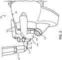
FIG. 2 is a perspective view of a laser measurement device, in accordance with various embodiments; -
FIG. 3 is a perspective view of a standoff fixture coupled to a mounting interface of a laser measurement device, in accordance with various embodiments; -
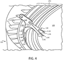
FIG. 4 is a perspective view of a standoff fixture engaged with a rotor disk, in accordance with various embodiments; -
FIG. 5 is a plan view of a standoff fixture engaged with a rotor disk, in accordance with various embodiments; -
FIG. 6A is a perspective view of a standoff fixture, in accordance with various embodiments; -
FIG. 6B is a plan view of a standoff fixture, in accordance with various embodiments; -
FIG. 7 is a perspective view of a standoff fixture engaged with a rotor disk, in accordance with various embodiments; -
FIG. 8 is a perspective view of a standoff fixture having a plurality of legs with dimensions that can be varied, in accordance with various embodiments; and -
FIG. 9 is a schematic block diagram of a method of inspecting a part, in accordance with various embodiments. - The subject matter of the present disclosure is particularly pointed out and distinctly claimed in the concluding end portion of the specification. A more complete understanding of the present disclosure, however, may best be obtained by referring to the detailed description and claims when considered in connection with the drawing figures, wherein like numerals denote like elements.
- The detailed description of exemplary embodiments herein makes reference to the accompanying drawings, which show exemplary embodiments by way of illustration. While these exemplary embodiments are described in sufficient detail to enable those skilled in the art to practice the disclosure, it should be understood that other embodiments may be realized and that logical changes and adaptations in design and construction may be made in accordance with this disclosure and the teachings herein without departing from the scope of the disclosure. Thus, the detailed description herein is presented for purposes of illustration only and not of limitation.
- Disclosed herein, according to various embodiments, are methods, devices, assemblies, and systems for inspecting a part. More specifically, the present provides for standoff fixtures that are customized for a specific part (or at least a specific type of part) and that are configured to be coupled to a laser measurement device to facilitate accuracy, repeatability, and reproducibility of inspection procedures, according to various embodiments. While numerous details are included herein pertaining to standoff fixture that are used for inspecting components of a gas turbine engine (such as rotor disks), the standoff fixtures and the associated methods/systems may be used to inspect other components/parts.
- In various embodiments and with reference to
FIG. 1 , agas turbine engine 20 is provided.Gas turbine engine 20 may be a two-spool turbofan that generally incorporates a fan section 22, acompressor section 24, acombustor section 26 and aturbine section 28. In operation, fan section 22 can drive fluid (e.g., air) along a bypass flow-path B whilecompressor section 24 can drive fluid along a core flow-path C for compression and communication intocombustor section 26 then expansion throughturbine section 28. Although depicted as a turbofangas turbine engine 20 herein, it should be understood that the concepts described herein are not limited to use with turbofans as the teachings may be applied to other types of turbine engines including three-spool architectures. -
Gas turbine engine 20 may generally comprise alow speed spool 30 and ahigh speed spool 32 mounted for rotation about an engine central longitudinal axis A-A' relative to an enginestatic structure 36 or engine case viaseveral bearing systems 38, 38-1, and 38-2. Engine central longitudinal axis A-A' is oriented in the z direction (axial direction) on the provided xyz axis. The y direction on the provided xyz axis refers to a radial direction, and the x direction on the provided xyz axis refers to a circumferential direction. It should be understood thatvarious bearing systems 38 at various locations may alternatively or additionally be provided, including for example,bearing system 38, bearing system 38-1, and bearing system 38-2. -
Low speed spool 30 may generally comprise aninner shaft 40 that interconnects afan 42, alow pressure compressor 44 and alow pressure turbine 46.Inner shaft 40 may be connected tofan 42 through a gearedarchitecture 48 that can drivefan 42 at a lower speed thanlow speed spool 30. Gearedarchitecture 48 may comprise agear assembly 60 enclosed within agear housing 62.Gear assembly 60 couplesinner shaft 40 to a rotating fan structure.High speed spool 32 may comprise anouter shaft 50 that interconnects ahigh pressure compressor 52 andhigh pressure turbine 54. - A
combustor 56 may be located betweenhigh pressure compressor 52 andhigh pressure turbine 54. Thecombustor section 26 may have an annular wall assembly having inner and outer shells that support respective inner and outer heat shielding liners. The heat shield liners may include a plurality of combustor panels that collectively define the annular combustion chamber of thecombustor 56. An annular cooling cavity is defined between the respective shells and combustor panels for supplying cooling air. Impingement holes are located in the shell to supply the cooling air from an outer air plenum and into the annular cooling cavity. - A
mid-turbine frame 57 of enginestatic structure 36 may be located generally betweenhigh pressure turbine 54 andlow pressure turbine 46.Mid-turbine frame 57 may support one ormore bearing systems 38 inturbine section 28.Inner shaft 40 andouter shaft 50 may be concentric and rotate via bearingsystems 38 about the engine central longitudinal axis A-A', which is collinear with their longitudinal axes. As used herein, a "high pressure" compressor or turbine experiences a higher pressure than a corresponding "low pressure" compressor or turbine. - The core airflow C may be compressed by
low pressure compressor 44 thenhigh pressure compressor 52, mixed and burned with fuel incombustor 56, then expanded overhigh pressure turbine 54 andlow pressure turbine 46.Turbines low speed spool 30 andhigh speed spool 32 in response to the expansion. - In various embodiments, geared
architecture 48 may be an epicyclic gear train, such as a star gear system (sun gear in meshing engagement with a plurality of star gears supported by a carrier and in meshing engagement with a ring gear) or other gear system.Geared architecture 48 may have a gear reduction ratio of greater than about 2.3 andlow pressure turbine 46 may have a pressure ratio that is greater than about five (5). In various embodiments, the bypass ratio ofgas turbine engine 20 is greater than about ten (10:1). In various embodiments, the diameter offan 42 may be significantly larger than that of thelow pressure compressor 44, and thelow pressure turbine 46 may have a pressure ratio that is greater than about five (5:1).Low pressure turbine 46 pressure ratio may be measured prior to inlet oflow pressure turbine 46 as related to the pressure at the outlet oflow pressure turbine 46 prior to an exhaust nozzle. It should be understood, however, that the above parameters are exemplary of various embodiments of a suitable geared architecture engine and that the present disclosure contemplates other gas turbine engines including direct drive turbofans. A gas turbine engine may comprise an industrial gas turbine (IGT) or a geared aircraft engine, such as a geared turbofan, or non-geared aircraft engine, such as a turbofan, or may comprise any gas turbine engine as desired. - In various embodiments, and with reference to
FIG. 2 , alaser measurement device 105 is provided. Thelaser measurement device 105 includes one or more emitters, such asemitter 106, and one or more sensors, and the emitter(s) and sensors are generally configured to measure a geometric specification of a part, such asgeneric part 80, according to various embodiments. For example, a laser signal may be emitted from theemitter 106 toward the part be measured, and the sensor(s) of thelaser measurement device 105 may detect geometric specification data in response to the emitted laser. Conventional laser measurement devices typically include aspacer 90 configured to be positioned between the laser measurement device and the part(s) 80 to be inspected. Generally, thespacer 90 helps to locate the part 80 a proper distance away from the one or more emitters and sensors so the appropriate/desiredfeature 81 of thepart 80 is properly positioned in the field-of-view of thelaser measurement device 105. However, as mentioned above,spacer 90 may not sufficiently restrain thelaser measurement device 105 relative to thepart 80, and thus the orientation, tilt, and/or rotation of thelaser measurement device 105 relative to thepart 80 can vary from one user to another or from one inspection to another. These variations decrease the repeatability and reproducibility of inspections, and thus adversely affect the accuracy of the inspection data. - In various embodiments, and with reference to
FIG. 9 , the present disclosure provides amethod 990 of inspecting a part that overcomes the aforementioned shortcomings. Themethod 990 generally includes manufacturing a standoff fixture that is specific to the part atstep 992, according to various embodiments. That is, instead of using a generic spacer, such asspacer 90,step 992 of themethod 990 may include fabricating a custom standoff fixture to be coupled to a laser measurement device and positioned between the laser measurement device and the part to be inspected. Generally, the standoff fixture increases the repeatability, reproducibility, and overall accuracy of theinspection method 990, according to various embodiments. - At
step 992 the standoff fixture may be specifically designed and manufactured for use with a specific part, or a specific type of part. For example, and as described in greater detail below, the part may be a component of a gas turbine engine 20 (FIG. 1 ), such as a rotor disk, and step 992 of themethod 990 may include designing a standoff fixture having a plurality of legs that are precisely seated/engaged against the part. The customized standoff fixture may utilized to facilitate inspection of multiple instances of the same part. In various embodiments, future inspections of the part, or future inspections of similar/comparable parts, are performed with the laser measurement device uniformly and consistently aligned and positioned relative to the part. Additional details pertaining to customized standoff fixtures are included below. - In various embodiments, the
method 990 further includes coupling the standoff fixture to a laser measurement device atstep 994, engaging the standoff fixture with the part to be inspected atstep 996, and actuating the laser measurement device to detect a geometric specification of a feature of the part atstep 998. In various embodiments,step 998 includes measuring more than one geometric specification of one or more features of the part. Further,step 996 may include engaging the standoff fixture to more than one part (e.g., separable parts) and step 998 may correspondingly include detecting geometric specification(s) of a plurality of parts. - In various embodiments, and with continued reference to
FIG. 9 , step 992 of themethod 990 may include determining/identifying a specific feature of a part to be inspected and subsequently designing and manufacturing the standoff fixture in such a manner so that duringstep 996 of themethod 990 the standoff fixture is seated in proximity to the feature/region of the part being inspected. Accordingly, step 992 may include manufacturing the standoff fixture to be specific to a feature of the part, and/or specific to a unique geometric specification of the feature of the part. In various embodiments,step 992 includes utilizing an additive manufacturing process to fabricate the standoff fixture. - In various embodiments, the standoff fixture includes a plurality of legs, as described in greater detail below. Step 992 may include specifically customized the shape, orientation, and/or extension direction of the legs based on the part and the feature of the part to be inspected. In various embodiments,
step 996 may include engaging the plurality of legs so that contact surfaces of the legs are properly seated against the part to thereby properly position the laser measurement device relative to the part. For example, the standoff fixture may be manufactured atstep 992 to have three legs (e.g., three points/locations of contact with the part), and thus the standoff fixture may benefit from tripod-like stability. In various embodiments,step 996 includes continuing to force the standoff fixture toward the part duringstep 998 to ensure the standoff fixture remains properly seated/engaged against the part. - In various embodiments, and with reference to
FIGS. 2 and3 , astandoff fixture 110 configured to be coupled to thelaser measurement device 105 is provided. InFIG. 3 , thelaser measurement device 105 is not shown in order to avoid obscuring the clear depiction of thestandoff fixture 110. However, mountingfeatures 108 of thelaser measurement device 105 are shown inFIG. 3 to show how thestandoff fixture 110 may be coupled to and oriented relative to thelaser measurement device 105. That is, thestandoff fixture 110 may include anattachment portion 119 configured to be coupled to mountingfeatures 108 of thelaser measurement device 105 usingfasteners 109 or other attachment mechanisms. - The
standoff fixture 110, according to various embodiments, includes a plurality of legs, such aslegs legs legs standoff fixture 110 may include afirst leg 112A having one ormore contact surfaces second leg 112B having one or more contact surfaces 113B, and athird leg 112C having one or more contact surfaces 113C. - In various embodiments, and with reference to
FIGS. 4 and5 , thestandoff fixture 110 is provided being positioned against a part to be inspected. During use (e.g., in practicing the method 990), thestandoff fixture 110 would be coupled/mounted to the laser measurement device 105 (FIG. 2 ), and then the standoff fixture would be engaged against the part in the orientation shown inFIGS. 4 and5 , according to various embodiments. However, in order to avoid obscuring a clear depiction of the features of thestandoff fixture 110 and the part against which it is engaged, the laser measurement device 105 (FIG. 2 ) is intentionally omitted fromFIGS. 4 and5 . - In various embodiments, the part to be inspected may be a
rotor disk 150 of thegas turbine engine 20, and thus thestandoff fixture 110 may be configured and specifically designed/manufactured to engage therotor disk 150. In various embodiments, because of the high rotational velocities of the rotor disks of a gas turbine engine, it may be important to ensure that rotor disks of a gas turbine engine are precisely manufactured in order to prevent damage to theblades 151 and/or other components of the gas turbine engine during operation. In various embodiments, the plurality oflegs rotor disk 150 in order to enable the laser measurement device 105 (FIG. 2 ) to be actuated to determine/detect a geometric specification of a specific feature/region of therotor disk 150. For example, thesecond leg 112B and thethird leg 112C of thestandoff fixture 110 may be configured to engage aweb 152 of therotor disk 150, and thefirst leg 112A may be configured to engage aflange 153 of therotor disk 150. More specifically, the second andthird legs web 152 of therotor disk 150 while thefirst leg 112A may comprise twocontact surfaces respective surfaces flange 153 of therotor disk 150. - In various embodiments, the feature being inspected is a
chamfer 155 of theflange 153 of therotor disk 150. For example, the laser measurement device 105 (FIG. 2 ), being properly positioned relative to therotor disk 150 via thestandoff fixture 110, may be configured to detect/determine an angle or a height of thechamfer 155. That is, the geometric specification may be an angle or dimension (e.g., height) of a chamfer. In various embodiments, thestandoff fixture 110 may be used to determine other geometric specifications, such as a radius of a feature. - In various embodiments, and with reference to
FIGS. 6A and 6B , thestandoff fixture 110 includes aplanar surface 116 that extends across/along theattachment portion 119 and at least one leg of the plurality oflegs planar surface 116 may be defined by, and thus may form a side of, theattachment portion 119 and one of the legs of the plurality of legs. For example, theplanar surface 116 may extend/continue from theattachment portion 119 to a side of thefirst leg 112A. Theplanar surface 116 may further extend/continue to form a side of thesecond leg 112B as well. In various embodiments, thethird leg 112C may be oriented oblique to theplanar surface 116. In various embodiments, no portion of thestandoff fixture 110 extends beyond the planar surface, thereby preventing any portion of thestandoff fixture 110 extending in to the field-of-view 115 of the laser measurement device 105 (FIG. 2 ). - In various embodiments, and with reference to
FIG. 7 , thestandoff fixture 210 may be configured to engage therotor disk 150 to facilitate measurement of a radius of the rotor disk (e.g., a radius of a section of theflange 153 of the rotor disk 150). In various embodiments, thestandoff fixture 210 includes anattachment portion 219, with threelegs attachment portion 219 and afourth leg 212D extending from a second side of theattachment portion 219. Each of thelegs more contact surfaces rotor disk 150. In various embodiments, the radius to be measured is generally between thefirst leg 212A and thefourth leg 212D. - In various embodiments, and with reference to
FIG. 8 , thestandoff fixture 310 may include a plurality oflegs legs standoff fixture 310 may be varied based on the specific feature to be inspected or based on the specific geometric specification to be determined. In various embodiments, for example, theattachment portion 319 may be a portion of abody 320 of thestandoff fixture 310, and thelegs body 320 of thestandoff fixture 310 to allow the distance of their respective heads from thebody 320 to be respectively adjusted based on the shape of the part being inspected. In various embodiments, thestandoff fixture 310 may be utilized to detect/determine the presence and/or magnitude of a mismatch between parts. - Benefits, other advantages, and solutions to problems have been described herein with regard to specific embodiments. Furthermore, the connecting lines shown in the various figures contained herein are intended to represent exemplary functional relationships and/or physical couplings between the various elements. It should be noted that many alternative or additional functional relationships or physical connections may be present in a practical system. However, the benefits, advantages, solutions to problems, and any elements that may cause any benefit, advantage, or solution to occur or become more pronounced are not to be construed as critical, required, or essential features or elements of the disclosure.
- The scope of the disclosure is accordingly to be limited by nothing other than the appended claims, in which reference to an element in the singular is not intended to mean "one and only one" unless explicitly so stated, but rather "one or more." It is to be understood that unless specifically stated otherwise, references to "a," "an," and/or "the" may include one or more than one and that reference to an item in the singular may also include the item in the plural. All ranges and ratio limits disclosed herein may be combined.
- Moreover, where a phrase similar to "at least one of A, B, and C" is used in the claims, it is intended that the phrase be interpreted to mean that A alone may be present in an embodiment, B alone may be present in an embodiment, C alone may be present in an embodiment, or that any combination of the elements A, B and C may be present in a single embodiment; for example, A and B, A and C, B and C, or A and B and C. Different cross-hatching is used throughout the figures to denote different parts but not necessarily to denote the same or different materials.
- The steps recited in any of the method or process descriptions may be executed in any order and are not necessarily limited to the order presented. Furthermore, any reference to singular includes plural embodiments, and any reference to more than one component or step may include a singular embodiment or step. Elements and steps in the figures are illustrated for simplicity and clarity and have not necessarily been rendered according to any particular sequence. For example, steps that may be performed concurrently or in different order are illustrated in the figures to help to improve understanding of embodiments of the present disclosure.
- Any reference to attached, fixed, connected or the like may include permanent, removable, temporary, partial, full and/or any other possible attachment option. Additionally, any reference to without contact (or similar phrases) may also include reduced contact or minimal contact. Surface shading lines may be used throughout the figures to denote different parts or areas but not necessarily to denote the same or different materials. In some cases, reference coordinates may be specific to each figure.
- Systems, methods and apparatus are provided herein. In the detailed description herein, references to "one embodiment," "an embodiment," "various embodiments," etc., indicate that the embodiment described may include a particular feature, structure, or characteristic, but every embodiment may not necessarily include the particular feature, structure, or characteristic. Moreover, such phrases are not necessarily referring to the same embodiment. Further, when a particular feature, structure, or characteristic is described in connection with an embodiment, it is submitted that it may be within the knowledge of one skilled in the art to affect such feature, structure, or characteristic in connection with other embodiments whether or not explicitly described. After reading the description, it will be apparent to one skilled in the relevant art(s) how to implement the disclosure in alternative embodiments.
- Furthermore, no element, component, or method step in the present disclosure is intended to be dedicated to the public regardless of whether the element, component, or method step is explicitly recited in the claims. No claim element is intended to invoke 35 U.S.C. 112(f) unless the element is expressly recited using the phrase "means for." As used herein, the terms "comprises," "comprising," or any other variation thereof, are intended to cover a non-exclusive inclusion, such that a process, method, article, or apparatus that comprises a list of elements does not include only those elements but may include other elements not expressly listed or inherent to such process, method, article, or apparatus.
Claims (15)
- A method of inspecting a part, the method comprising:manufacturing a standoff fixture specific to the part;coupling the standoff fixture to a laser measurement device;engaging the standoff fixture with the part; andactuating the laser measurement device to detect a geometric specification of a feature of the part.
- The method of claim 1, wherein manufacturing the standoff fixture comprises manufacturing the standoff fixture specific to the feature of the part.
- The method of claim 1 or 2, wherein the standoff fixture comprises a plurality of legs, wherein manufacturing the standoff fixture comprises manufacturing the plurality of legs of the standoff fixture specific to the feature of the part.
- The method of claim 3, wherein engaging the standoff fixture with the part comprises engaging the plurality of legs against the part.
- The method of claim 3 or 4, wherein:the part comprises a rotor disk of a gas turbine engine;engaging the plurality of legs against the part comprises engaging a first leg of the plurality of legs against a web of the rotor disk; andengaging the plurality of legs against the part comprises engaging a second leg of the plurality of legs against a flange of the rotor disk.
- The method of claim 5, wherein the feature of the part comprises a chamfer of the flange of the rotor disk.
- The method of claim 6, wherein the geometric specification is an angle of the chamfer.
- The method of claim 6, wherein the geometric specification is a dimension of the chamfer.
- The method of any preceding claim, wherein manufacturing the standoff fixture comprises using an additive manufacturing process.
- The method of any of claims 2 to 9, wherein the standoff fixture comprises three legs, wherein engaging the standoff fixture with the part comprises engaging the three legs against the part, and / or wherein the geometric specification of the feature comprises at least one of a radius, a mismatch, a chamfer angle, and a chamfer height.
- A standoff fixture for a laser measurement device, the standoff fixture comprising:an attachment portion configured to be coupled to the laser measurement device; anda plurality of legs extending from the attachment portion, wherein the plurality of legs are configured to engage with a part to be inspected;wherein the plurality of legs are specific to the part to be inspected.
- The standoff fixture of claim 11, wherein each leg of the plurality of legs is oriented specific to the part to be inspected, and / or wherein the plurality of legs comprise, respectively, a plurality of contact surfaces, wherein an orientation of each contact surface of the plurality of contact surfaces is specific to the part be inspected, and / or wherein the plurality of legs comprises three legs.
- The standoff fixture of claim 11 or 12, wherein the standoff fixture comprises a planar surface extending from the attachment portion to a first leg of the plurality of legs such that the planar surface forms a portion of the attachment portion and a portion of the first leg, wherein, optionally, the planar surface extends to a second leg of the plurality of legs such that the planar surface forms a portion of the second leg, wherein, optionally, the plurality of legs comprises a third leg, wherein the third leg is oriented oblique to the planar surface.
- An inspection assembly for inspecting a part, the inspection assembly comprising:a laser measurement device; anda standoff fixture detachably coupleable to the laser measurement device, wherein the standoff fixture comprises:an attachment portion for coupling to the laser measurement device; anda plurality of legs extending from the attachment portion;wherein the plurality of legs are configured to engage with the part; andwherein the standoff fixture is specific to the part.
- The inspection assembly of claim 14, wherein the plurality of legs are specific to the part.
Applications Claiming Priority (1)
| Application Number | Priority Date | Filing Date | Title |
|---|---|---|---|
| US16/366,513 US10690491B1 (en) | 2019-03-27 | 2019-03-27 | Standoff fixture for laser inspection |
Publications (2)
| Publication Number | Publication Date |
|---|---|
| EP3715816A1 true EP3715816A1 (en) | 2020-09-30 |
| EP3715816B1 EP3715816B1 (en) | 2024-06-12 |
Family
ID=70464813
Family Applications (1)
| Application Number | Title | Priority Date | Filing Date |
|---|---|---|---|
| EP20166029.7A Active EP3715816B1 (en) | 2019-03-27 | 2020-03-26 | Standoff fixture for laser inspection |
Country Status (2)
| Country | Link |
|---|---|
| US (1) | US10690491B1 (en) |
| EP (1) | EP3715816B1 (en) |
Families Citing this family (1)
| Publication number | Priority date | Publication date | Assignee | Title |
|---|---|---|---|---|
| US12462477B2 (en) | 2023-05-04 | 2025-11-04 | Pratt & Whitney Canada Corp. | Method and system for scanning a part by performing compensation or transformation of scanned part data |
Citations (4)
| Publication number | Priority date | Publication date | Assignee | Title |
|---|---|---|---|---|
| DE20018414U1 (en) * | 2000-10-27 | 2001-01-18 | Mahr, Helmut, 86720 Nördlingen | Device for fastening measuring devices to the wheel of a vehicle |
| CN103862406B (en) * | 2014-03-28 | 2016-03-02 | 深圳市米勒沙容达汽车科技有限公司 | A kind of be applied to four-wheel position finder exempt from compensate three-point fix fixture |
| US20170268963A1 (en) * | 2016-03-17 | 2017-09-21 | Honeywell International Inc. | Structured light measuring apparatus and methods |
| US20190017440A1 (en) * | 2017-07-17 | 2019-01-17 | United Technologies Corporation | Combustor panel standoffs with cooling holes |
Family Cites Families (11)
| Publication number | Priority date | Publication date | Assignee | Title |
|---|---|---|---|---|
| FR2756626B1 (en) | 1996-12-02 | 1999-02-19 | Espace Ind Controle Sa | SYSTEM FOR MEASURING GAMES AND FLOORS BETWEEN OPPOSITE PARTS |
| US6804006B2 (en) * | 2002-07-02 | 2004-10-12 | E. I. Du Pont De Nemours And Company | Color sample holder to enhance repeatability of instrumental color readings |
| US7433027B2 (en) * | 2004-12-22 | 2008-10-07 | Novartis Ag | Apparatus and method for detecting lens thickness |
| TWI325494B (en) * | 2006-07-28 | 2010-06-01 | Ind Tech Res Inst | Optical measuring system |
| US7542135B2 (en) * | 2007-06-06 | 2009-06-02 | Northrop Grumman Corporation | Device for inspecting countersunk holes |
| FR2940437B1 (en) * | 2008-12-22 | 2013-02-15 | Airbus France | TOOL, TOOL ASSEMBLY, AND METHOD OF ADJUSTING THE FLANGE OF BLADES OF A MODEL PROPELLER |
| JP5274492B2 (en) * | 2009-01-30 | 2013-08-28 | 富士フイルム株式会社 | Measuring object holder, living body holder, and optical measuring device |
| EP2312268A1 (en) * | 2009-10-16 | 2011-04-20 | Straumann Holding AG | Scanning device for scanning dental objects and a method for scanning dental objects |
| US20130021604A1 (en) * | 2011-07-20 | 2013-01-24 | Richard Sun | Automated Sample Positioning System For Ellipsometers |
| US9013716B2 (en) * | 2012-11-27 | 2015-04-21 | Third Dimension Software Limited | Positioning device for an optical triangulation sensor |
| GB201401437D0 (en) | 2014-01-28 | 2014-03-12 | Third Dimension Software Ltd | Positioning device for an optical triangulation sensor |
-
2019
- 2019-03-27 US US16/366,513 patent/US10690491B1/en active Active
-
2020
- 2020-03-26 EP EP20166029.7A patent/EP3715816B1/en active Active
Patent Citations (4)
| Publication number | Priority date | Publication date | Assignee | Title |
|---|---|---|---|---|
| DE20018414U1 (en) * | 2000-10-27 | 2001-01-18 | Mahr, Helmut, 86720 Nördlingen | Device for fastening measuring devices to the wheel of a vehicle |
| CN103862406B (en) * | 2014-03-28 | 2016-03-02 | 深圳市米勒沙容达汽车科技有限公司 | A kind of be applied to four-wheel position finder exempt from compensate three-point fix fixture |
| US20170268963A1 (en) * | 2016-03-17 | 2017-09-21 | Honeywell International Inc. | Structured light measuring apparatus and methods |
| US20190017440A1 (en) * | 2017-07-17 | 2019-01-17 | United Technologies Corporation | Combustor panel standoffs with cooling holes |
Also Published As
| Publication number | Publication date |
|---|---|
| US10690491B1 (en) | 2020-06-23 |
| EP3715816B1 (en) | 2024-06-12 |
Similar Documents
| Publication | Publication Date | Title |
|---|---|---|
| US10775269B2 (en) | Blade health inspection using an excitation actuator and vibration sensor | |
| US10871402B2 (en) | Device for measuring the characteristics of an air flow | |
| EP3580433B1 (en) | Pressure sensor assembly for a turbine engine | |
| US10619857B2 (en) | Cooling configuration for combustor attachment feature | |
| US10598041B2 (en) | Inlet performance measurement system for gas turbine engine | |
| US7017431B2 (en) | Methods for inspecting components | |
| US10364688B2 (en) | Minidisk balance flange | |
| EP3715816B1 (en) | Standoff fixture for laser inspection | |
| US20190285276A1 (en) | Castellated combustor panels | |
| EP3663516A1 (en) | Component inspection using measured and theoretical moment weights | |
| EP4206637B1 (en) | Vacuum testing a seal within a gas turbine engine structure | |
| US11085759B2 (en) | Calibration for laser inspection | |
| US10232474B2 (en) | Gas turbine engine components and method of assembly | |
| EP3382278A1 (en) | Combustor panel heat transfer pins with varying geometric specifications and method of manufacturing the panel | |
| US7246419B2 (en) | Impeller clearance tool | |
| US10458244B2 (en) | Tuned retention ring for rotor disk | |
| EP4400693A1 (en) | Computationally balancing a rotating structure | |
| Blair et al. | Axial-centrifugal compressor program |
Legal Events
| Date | Code | Title | Description |
|---|---|---|---|
| PUAI | Public reference made under article 153(3) epc to a published international application that has entered the european phase |
Free format text: ORIGINAL CODE: 0009012 |
|
| STAA | Information on the status of an ep patent application or granted ep patent |
Free format text: STATUS: THE APPLICATION HAS BEEN PUBLISHED |
|
| AK | Designated contracting states |
Kind code of ref document: A1 Designated state(s): AL AT BE BG CH CY CZ DE DK EE ES FI FR GB GR HR HU IE IS IT LI LT LU LV MC MK MT NL NO PL PT RO RS SE SI SK SM TR |
|
| AX | Request for extension of the european patent |
Extension state: BA ME |
|
| RAP1 | Party data changed (applicant data changed or rights of an application transferred) |
Owner name: RAYTHEON TECHNOLOGIES CORPORATION |
|
| STAA | Information on the status of an ep patent application or granted ep patent |
Free format text: STATUS: REQUEST FOR EXAMINATION WAS MADE |
|
| 17P | Request for examination filed |
Effective date: 20210330 |
|
| RBV | Designated contracting states (corrected) |
Designated state(s): AL AT BE BG CH CY CZ DE DK EE ES FI FR GB GR HR HU IE IS IT LI LT LU LV MC MK MT NL NO PL PT RO RS SE SI SK SM TR |
|
| STAA | Information on the status of an ep patent application or granted ep patent |
Free format text: STATUS: EXAMINATION IS IN PROGRESS |
|
| 17Q | First examination report despatched |
Effective date: 20211206 |
|
| RAP3 | Party data changed (applicant data changed or rights of an application transferred) |
Owner name: RTX CORPORATION |
|
| GRAP | Despatch of communication of intention to grant a patent |
Free format text: ORIGINAL CODE: EPIDOSNIGR1 |
|
| STAA | Information on the status of an ep patent application or granted ep patent |
Free format text: STATUS: GRANT OF PATENT IS INTENDED |
|
| INTG | Intention to grant announced |
Effective date: 20240108 |
|
| GRAS | Grant fee paid |
Free format text: ORIGINAL CODE: EPIDOSNIGR3 |
|
| GRAA | (expected) grant |
Free format text: ORIGINAL CODE: 0009210 |
|
| STAA | Information on the status of an ep patent application or granted ep patent |
Free format text: STATUS: THE PATENT HAS BEEN GRANTED |
|
| AK | Designated contracting states |
Kind code of ref document: B1 Designated state(s): AL AT BE BG CH CY CZ DE DK EE ES FI FR GB GR HR HU IE IS IT LI LT LU LV MC MK MT NL NO PL PT RO RS SE SI SK SM TR |
|
| REG | Reference to a national code |
Ref country code: GB Ref legal event code: FG4D |
|
| REG | Reference to a national code |
Ref country code: CH Ref legal event code: EP |
|
| REG | Reference to a national code |
Ref country code: DE Ref legal event code: R096 Ref document number: 602020032178 Country of ref document: DE |
|
| REG | Reference to a national code |
Ref country code: IE Ref legal event code: FG4D |
|
| PG25 | Lapsed in a contracting state [announced via postgrant information from national office to epo] |
Ref country code: BG Free format text: LAPSE BECAUSE OF FAILURE TO SUBMIT A TRANSLATION OF THE DESCRIPTION OR TO PAY THE FEE WITHIN THE PRESCRIBED TIME-LIMIT Effective date: 20240612 |
|
| PG25 | Lapsed in a contracting state [announced via postgrant information from national office to epo] |
Ref country code: FI Free format text: LAPSE BECAUSE OF FAILURE TO SUBMIT A TRANSLATION OF THE DESCRIPTION OR TO PAY THE FEE WITHIN THE PRESCRIBED TIME-LIMIT Effective date: 20240612 Ref country code: HR Free format text: LAPSE BECAUSE OF FAILURE TO SUBMIT A TRANSLATION OF THE DESCRIPTION OR TO PAY THE FEE WITHIN THE PRESCRIBED TIME-LIMIT Effective date: 20240612 |
|
| REG | Reference to a national code |
Ref country code: LT Ref legal event code: MG9D |
|
| PG25 | Lapsed in a contracting state [announced via postgrant information from national office to epo] |
Ref country code: GR Free format text: LAPSE BECAUSE OF FAILURE TO SUBMIT A TRANSLATION OF THE DESCRIPTION OR TO PAY THE FEE WITHIN THE PRESCRIBED TIME-LIMIT Effective date: 20240913 |
|
| REG | Reference to a national code |
Ref country code: NL Ref legal event code: MP Effective date: 20240612 |
|
| PG25 | Lapsed in a contracting state [announced via postgrant information from national office to epo] |
Ref country code: ES Free format text: LAPSE BECAUSE OF FAILURE TO SUBMIT A TRANSLATION OF THE DESCRIPTION OR TO PAY THE FEE WITHIN THE PRESCRIBED TIME-LIMIT Effective date: 20240612 |
|
| PG25 | Lapsed in a contracting state [announced via postgrant information from national office to epo] |
Ref country code: LV Free format text: LAPSE BECAUSE OF FAILURE TO SUBMIT A TRANSLATION OF THE DESCRIPTION OR TO PAY THE FEE WITHIN THE PRESCRIBED TIME-LIMIT Effective date: 20240612 |
|
| PG25 | Lapsed in a contracting state [announced via postgrant information from national office to epo] |
Ref country code: NO Free format text: LAPSE BECAUSE OF FAILURE TO SUBMIT A TRANSLATION OF THE DESCRIPTION OR TO PAY THE FEE WITHIN THE PRESCRIBED TIME-LIMIT Effective date: 20240912 Ref country code: LV Free format text: LAPSE BECAUSE OF FAILURE TO SUBMIT A TRANSLATION OF THE DESCRIPTION OR TO PAY THE FEE WITHIN THE PRESCRIBED TIME-LIMIT Effective date: 20240612 Ref country code: HR Free format text: LAPSE BECAUSE OF FAILURE TO SUBMIT A TRANSLATION OF THE DESCRIPTION OR TO PAY THE FEE WITHIN THE PRESCRIBED TIME-LIMIT Effective date: 20240612 Ref country code: GR Free format text: LAPSE BECAUSE OF FAILURE TO SUBMIT A TRANSLATION OF THE DESCRIPTION OR TO PAY THE FEE WITHIN THE PRESCRIBED TIME-LIMIT Effective date: 20240913 Ref country code: FI Free format text: LAPSE BECAUSE OF FAILURE TO SUBMIT A TRANSLATION OF THE DESCRIPTION OR TO PAY THE FEE WITHIN THE PRESCRIBED TIME-LIMIT Effective date: 20240612 Ref country code: ES Free format text: LAPSE BECAUSE OF FAILURE TO SUBMIT A TRANSLATION OF THE DESCRIPTION OR TO PAY THE FEE WITHIN THE PRESCRIBED TIME-LIMIT Effective date: 20240612 Ref country code: BG Free format text: LAPSE BECAUSE OF FAILURE TO SUBMIT A TRANSLATION OF THE DESCRIPTION OR TO PAY THE FEE WITHIN THE PRESCRIBED TIME-LIMIT Effective date: 20240612 Ref country code: RS Free format text: LAPSE BECAUSE OF FAILURE TO SUBMIT A TRANSLATION OF THE DESCRIPTION OR TO PAY THE FEE WITHIN THE PRESCRIBED TIME-LIMIT Effective date: 20240912 |
|
| PG25 | Lapsed in a contracting state [announced via postgrant information from national office to epo] |
Ref country code: NL Free format text: LAPSE BECAUSE OF FAILURE TO SUBMIT A TRANSLATION OF THE DESCRIPTION OR TO PAY THE FEE WITHIN THE PRESCRIBED TIME-LIMIT Effective date: 20240612 |
|
| REG | Reference to a national code |
Ref country code: AT Ref legal event code: MK05 Ref document number: 1694658 Country of ref document: AT Kind code of ref document: T Effective date: 20240612 |
|
| PG25 | Lapsed in a contracting state [announced via postgrant information from national office to epo] |
Ref country code: NL Free format text: LAPSE BECAUSE OF FAILURE TO SUBMIT A TRANSLATION OF THE DESCRIPTION OR TO PAY THE FEE WITHIN THE PRESCRIBED TIME-LIMIT Effective date: 20240612 |
|
| PG25 | Lapsed in a contracting state [announced via postgrant information from national office to epo] |
Ref country code: PT Free format text: LAPSE BECAUSE OF FAILURE TO SUBMIT A TRANSLATION OF THE DESCRIPTION OR TO PAY THE FEE WITHIN THE PRESCRIBED TIME-LIMIT Effective date: 20241014 |
|
| PG25 | Lapsed in a contracting state [announced via postgrant information from national office to epo] |
Ref country code: PT Free format text: LAPSE BECAUSE OF FAILURE TO SUBMIT A TRANSLATION OF THE DESCRIPTION OR TO PAY THE FEE WITHIN THE PRESCRIBED TIME-LIMIT Effective date: 20241014 |
|
| PG25 | Lapsed in a contracting state [announced via postgrant information from national office to epo] |
Ref country code: PL Free format text: LAPSE BECAUSE OF FAILURE TO SUBMIT A TRANSLATION OF THE DESCRIPTION OR TO PAY THE FEE WITHIN THE PRESCRIBED TIME-LIMIT Effective date: 20240612 |
|
| PG25 | Lapsed in a contracting state [announced via postgrant information from national office to epo] |
Ref country code: EE Free format text: LAPSE BECAUSE OF FAILURE TO SUBMIT A TRANSLATION OF THE DESCRIPTION OR TO PAY THE FEE WITHIN THE PRESCRIBED TIME-LIMIT Effective date: 20240612 |
|
| PG25 | Lapsed in a contracting state [announced via postgrant information from national office to epo] |
Ref country code: AT Free format text: LAPSE BECAUSE OF FAILURE TO SUBMIT A TRANSLATION OF THE DESCRIPTION OR TO PAY THE FEE WITHIN THE PRESCRIBED TIME-LIMIT Effective date: 20240612 Ref country code: IS Free format text: LAPSE BECAUSE OF FAILURE TO SUBMIT A TRANSLATION OF THE DESCRIPTION OR TO PAY THE FEE WITHIN THE PRESCRIBED TIME-LIMIT Effective date: 20241012 |
|
| PG25 | Lapsed in a contracting state [announced via postgrant information from national office to epo] |
Ref country code: CZ Free format text: LAPSE BECAUSE OF FAILURE TO SUBMIT A TRANSLATION OF THE DESCRIPTION OR TO PAY THE FEE WITHIN THE PRESCRIBED TIME-LIMIT Effective date: 20240612 |
|
| PG25 | Lapsed in a contracting state [announced via postgrant information from national office to epo] |
Ref country code: RO Free format text: LAPSE BECAUSE OF FAILURE TO SUBMIT A TRANSLATION OF THE DESCRIPTION OR TO PAY THE FEE WITHIN THE PRESCRIBED TIME-LIMIT Effective date: 20240612 Ref country code: SK Free format text: LAPSE BECAUSE OF FAILURE TO SUBMIT A TRANSLATION OF THE DESCRIPTION OR TO PAY THE FEE WITHIN THE PRESCRIBED TIME-LIMIT Effective date: 20240612 |
|
| PG25 | Lapsed in a contracting state [announced via postgrant information from national office to epo] |
Ref country code: SM Free format text: LAPSE BECAUSE OF FAILURE TO SUBMIT A TRANSLATION OF THE DESCRIPTION OR TO PAY THE FEE WITHIN THE PRESCRIBED TIME-LIMIT Effective date: 20240612 |
|
| PG25 | Lapsed in a contracting state [announced via postgrant information from national office to epo] |
Ref country code: SM Free format text: LAPSE BECAUSE OF FAILURE TO SUBMIT A TRANSLATION OF THE DESCRIPTION OR TO PAY THE FEE WITHIN THE PRESCRIBED TIME-LIMIT Effective date: 20240612 Ref country code: SK Free format text: LAPSE BECAUSE OF FAILURE TO SUBMIT A TRANSLATION OF THE DESCRIPTION OR TO PAY THE FEE WITHIN THE PRESCRIBED TIME-LIMIT Effective date: 20240612 Ref country code: RO Free format text: LAPSE BECAUSE OF FAILURE TO SUBMIT A TRANSLATION OF THE DESCRIPTION OR TO PAY THE FEE WITHIN THE PRESCRIBED TIME-LIMIT Effective date: 20240612 Ref country code: PL Free format text: LAPSE BECAUSE OF FAILURE TO SUBMIT A TRANSLATION OF THE DESCRIPTION OR TO PAY THE FEE WITHIN THE PRESCRIBED TIME-LIMIT Effective date: 20240612 Ref country code: IS Free format text: LAPSE BECAUSE OF FAILURE TO SUBMIT A TRANSLATION OF THE DESCRIPTION OR TO PAY THE FEE WITHIN THE PRESCRIBED TIME-LIMIT Effective date: 20241012 Ref country code: EE Free format text: LAPSE BECAUSE OF FAILURE TO SUBMIT A TRANSLATION OF THE DESCRIPTION OR TO PAY THE FEE WITHIN THE PRESCRIBED TIME-LIMIT Effective date: 20240612 Ref country code: CZ Free format text: LAPSE BECAUSE OF FAILURE TO SUBMIT A TRANSLATION OF THE DESCRIPTION OR TO PAY THE FEE WITHIN THE PRESCRIBED TIME-LIMIT Effective date: 20240612 Ref country code: AT Free format text: LAPSE BECAUSE OF FAILURE TO SUBMIT A TRANSLATION OF THE DESCRIPTION OR TO PAY THE FEE WITHIN THE PRESCRIBED TIME-LIMIT Effective date: 20240612 |
|
| PG25 | Lapsed in a contracting state [announced via postgrant information from national office to epo] |
Ref country code: IT Free format text: LAPSE BECAUSE OF FAILURE TO SUBMIT A TRANSLATION OF THE DESCRIPTION OR TO PAY THE FEE WITHIN THE PRESCRIBED TIME-LIMIT Effective date: 20240612 |
|
| REG | Reference to a national code |
Ref country code: DE Ref legal event code: R097 Ref document number: 602020032178 Country of ref document: DE |
|
| PG25 | Lapsed in a contracting state [announced via postgrant information from national office to epo] |
Ref country code: DK Free format text: LAPSE BECAUSE OF FAILURE TO SUBMIT A TRANSLATION OF THE DESCRIPTION OR TO PAY THE FEE WITHIN THE PRESCRIBED TIME-LIMIT Effective date: 20240612 |
|
| PLBE | No opposition filed within time limit |
Free format text: ORIGINAL CODE: 0009261 |
|
| STAA | Information on the status of an ep patent application or granted ep patent |
Free format text: STATUS: NO OPPOSITION FILED WITHIN TIME LIMIT |
|
| 26N | No opposition filed |
Effective date: 20250313 |
|
| PG25 | Lapsed in a contracting state [announced via postgrant information from national office to epo] |
Ref country code: SE Free format text: LAPSE BECAUSE OF FAILURE TO SUBMIT A TRANSLATION OF THE DESCRIPTION OR TO PAY THE FEE WITHIN THE PRESCRIBED TIME-LIMIT Effective date: 20240612 |
|
| PG25 | Lapsed in a contracting state [announced via postgrant information from national office to epo] |
Ref country code: MC Free format text: LAPSE BECAUSE OF FAILURE TO SUBMIT A TRANSLATION OF THE DESCRIPTION OR TO PAY THE FEE WITHIN THE PRESCRIBED TIME-LIMIT Effective date: 20240612 |
|
| REG | Reference to a national code |
Ref country code: CH Ref legal event code: H13 Free format text: ST27 STATUS EVENT CODE: U-0-0-H10-H13 (AS PROVIDED BY THE NATIONAL OFFICE) Effective date: 20251024 |
|
| PG25 | Lapsed in a contracting state [announced via postgrant information from national office to epo] |
Ref country code: LU Free format text: LAPSE BECAUSE OF NON-PAYMENT OF DUE FEES Effective date: 20250326 |
|
| REG | Reference to a national code |
Ref country code: BE Ref legal event code: MM Effective date: 20250331 |
|
| PG25 | Lapsed in a contracting state [announced via postgrant information from national office to epo] |
Ref country code: BE Free format text: LAPSE BECAUSE OF NON-PAYMENT OF DUE FEES Effective date: 20250331 |
|
| PG25 | Lapsed in a contracting state [announced via postgrant information from national office to epo] |
Ref country code: CH Free format text: LAPSE BECAUSE OF NON-PAYMENT OF DUE FEES Effective date: 20250331 |
|
| PG25 | Lapsed in a contracting state [announced via postgrant information from national office to epo] |
Ref country code: IE Free format text: LAPSE BECAUSE OF NON-PAYMENT OF DUE FEES Effective date: 20250326 |
|
| PGFP | Annual fee paid to national office [announced via postgrant information from national office to epo] |
Ref country code: GB Payment date: 20260219 Year of fee payment: 7 |
|
| PGFP | Annual fee paid to national office [announced via postgrant information from national office to epo] |
Ref country code: DE Payment date: 20260219 Year of fee payment: 7 |
|
| PGFP | Annual fee paid to national office [announced via postgrant information from national office to epo] |
Ref country code: FR Payment date: 20260219 Year of fee payment: 7 |