EP3715783B1 - Point cloud data processing method and point cloud data processing device - Google Patents
Point cloud data processing method and point cloud data processing device Download PDFInfo
- Publication number
- EP3715783B1 EP3715783B1 EP20162366.7A EP20162366A EP3715783B1 EP 3715783 B1 EP3715783 B1 EP 3715783B1 EP 20162366 A EP20162366 A EP 20162366A EP 3715783 B1 EP3715783 B1 EP 3715783B1
- Authority
- EP
- European Patent Office
- Prior art keywords
- extraction
- point cloud
- cloud data
- trajectory
- distance
- Prior art date
- Legal status (The legal status is an assumption and is not a legal conclusion. Google has not performed a legal analysis and makes no representation as to the accuracy of the status listed.)
- Active
Links
Images






Classifications
-
- G—PHYSICS
- G01—MEASURING; TESTING
- G01C—MEASURING DISTANCES, LEVELS OR BEARINGS; SURVEYING; NAVIGATION; GYROSCOPIC INSTRUMENTS; PHOTOGRAMMETRY OR VIDEOGRAMMETRY
- G01C7/00—Tracing profiles
- G01C7/02—Tracing profiles of land surfaces
- G01C7/04—Tracing profiles of land surfaces involving a vehicle which moves along the profile to be traced
-
- G—PHYSICS
- G06—COMPUTING OR CALCULATING; COUNTING
- G06T—IMAGE DATA PROCESSING OR GENERATION, IN GENERAL
- G06T7/00—Image analysis
- G06T7/70—Determining position or orientation of objects or cameras
-
- G—PHYSICS
- G01—MEASURING; TESTING
- G01S—RADIO DIRECTION-FINDING; RADIO NAVIGATION; DETERMINING DISTANCE OR VELOCITY BY USE OF RADIO WAVES; LOCATING OR PRESENCE-DETECTING BY USE OF THE REFLECTION OR RERADIATION OF RADIO WAVES; ANALOGOUS ARRANGEMENTS USING OTHER WAVES
- G01S19/00—Satellite radio beacon positioning systems; Determining position, velocity or attitude using signals transmitted by such systems
- G01S19/38—Determining a navigation solution using signals transmitted by a satellite radio beacon positioning system
- G01S19/39—Determining a navigation solution using signals transmitted by a satellite radio beacon positioning system the satellite radio beacon positioning system transmitting time-stamped messages, e.g. GPS [Global Positioning System], GLONASS [Global Orbiting Navigation Satellite System] or GALILEO
- G01S19/393—Trajectory determination or predictive tracking, e.g. Kalman filtering
-
- G—PHYSICS
- G06—COMPUTING OR CALCULATING; COUNTING
- G06T—IMAGE DATA PROCESSING OR GENERATION, IN GENERAL
- G06T3/00—Geometric image transformations in the plane of the image
- G06T3/40—Scaling of whole images or parts thereof, e.g. expanding or contracting
-
- G—PHYSICS
- G06—COMPUTING OR CALCULATING; COUNTING
- G06V—IMAGE OR VIDEO RECOGNITION OR UNDERSTANDING
- G06V20/00—Scenes; Scene-specific elements
- G06V20/50—Context or environment of the image
- G06V20/56—Context or environment of the image exterior to a vehicle by using sensors mounted on the vehicle
-
- H—ELECTRICITY
- H04—ELECTRIC COMMUNICATION TECHNIQUE
- H04N—PICTORIAL COMMUNICATION, e.g. TELEVISION
- H04N23/00—Cameras or camera modules comprising electronic image sensors; Control thereof
- H04N23/90—Arrangement of cameras or camera modules, e.g. multiple cameras in TV studios or sports stadiums
-
- G—PHYSICS
- G06—COMPUTING OR CALCULATING; COUNTING
- G06T—IMAGE DATA PROCESSING OR GENERATION, IN GENERAL
- G06T2207/00—Indexing scheme for image analysis or image enhancement
- G06T2207/10—Image acquisition modality
- G06T2207/10028—Range image; Depth image; 3D point clouds
Definitions
- the present disclosure relates to a point cloud data processing method and a point cloud data processing device.
- an MMS Mobile Mapping System
- the MMS is configured by installing a measuring device including a GNSS (Global Navigation Satellite System), an antenna, an IMU (Inertial Measuring Unit), a camera, a laser scanner, etc., in a mobile body such as a vehicle.
- GNSS Global Navigation Satellite System
- IMU Inertial Measuring Unit
- a camera a laser scanner, etc.
- An MMS is a system intended to execute post-processing of data. Therefore, first, while traveling in a measurement section on a target road by vehicle, the MMS acquires data on its own position based on a GNSS navigation signal (hereinafter, referred to as "satellite positioning data"), three-dimensional acceleration and angular velocity data obtained by the IMU (hereinafter, referred to as “inertial positioning data”), and measurement data at each point of scanning light by the laser scanner (hereinafter, referred to as "measurement point cloud data”), and next, calculates a trajectory of the vehicle on the basis of the satellite positioning data and the inertial positioning data, and synthesizes the calculated trajectory of the vehicle and the point cloud data to generate three-dimensional point cloud data as a result.
- GNSS navigation signal hereinafter, referred to as "satellite positioning data”
- inertial positioning data three-dimensional acceleration and angular velocity data obtained by the IMU
- measurement point cloud data measurement data at each point of scanning light by the laser scanner
- the laser scanner acquires a point cloud over the entire circumference, so that acquired point cloud data includes a large number of point data due to structural objects other than an analysis target. Therefore, in order to analyze an analysis target, a portion including the analysis target needs to be manually extracted, and the extraction operation is troublesome.
- Patent Literature 1 discloses a point cloud data processing method in which a columnar region and a parallelepiped region disposed at predetermined positions on a lower side of the trajectory are set as extraction regions, and point data belonging to these extraction regions are extracted as target point cloud data.
- Patent Literature 1 International Publication WO 2018/159690
- the present invention was made in view of the above-described circumstances, and an object thereof is to provide a point cloud data processing method and a point cloud data processing device capable of easily extracting an analysis target from entire circumference point cloud data acquired by a measuring device that is moving along a measurement route.
- a point cloud data processing device according to claim 7 is also disclosed.
- an analysis target can be easily extracted from entire circumference point cloud data acquired by a measuring device that is moving along a measurement route.
- a point cloud data processing device is a device to execute post-processing of measurement data acquired by, for example, a measuring device 20 illustrated in FIG. 1 . First, the measuring device 20 will be described.
- the measuring device 20 is a so-called MMS (Mobile Mapping System).
- the measuring device 20 includes a GNSS device 21, an IMU 22, a camera 23, a laser scanner 24, a rotary encoder 25, and a synchronization control device 26, installed in a vehicle 27.
- the GNSS device 21 is a receiving device that receives a navigation signal from a navigation satellite 28 such as a GNSS satellite. Based on the navigation signal, the GNSS device 21 acquires satellite positioning data, that is, a plan position and an altitude of the measuring device 20. For example, the GNSS device 21 acquires coordinates of the measuring device 20 at intervals of ten times/second.
- the IMU 22 is an inertial measuring device, includes a three axis gyroscope and a 3-directional accelerometer, and acquires inertial positioning data.
- the camera 23 is a 360-degree camera consisting of a plurality of cameras, and shoots a video of the entire circumference (2 ⁇ space) including an upper direction.
- video image data shot by the camera 23 is used for construction of three-dimensional information of the surroundings in combination with point cloud data measured by the laser scanner 24.
- Exterior orientation elements (positions and postures) of the camera 23 and the laser scanner 24 with respect to the measuring device 20 are measured in advance, and such information is known.
- the laser scanner 24 spirally irradiates a scanning light La onto the entire circumference (2 ⁇ space), and receives a reflected light Lb ( FIG. 1B ) from a structural object such as a road 30, a building, and a tree. Based on a time from emission of the scanning light La until reception of the reflected light Lb, the laser scanner 24 obtains a three-dimensional position of each reflection point, to acquire point cloud data over the entire circumference of the laser scanner 24.
- the laser scanner 24 acquires measurement point cloud data as the entire circumference point cloud data of a scanning range 32 along a measurement route.
- the laser scanner 24 is one in number. However, the number is not limited to this.
- the measuring device 20 may include a plurality of laser scanners 24 such as three or five. When the number of laser scanners 24 is increased, the point cloud density increases, and shadow portions can be minimized, so that a measurement with higher accuracy can be made.
- the rotary encoder 25 is attached to a wheel 29 of the vehicle 27, and acquires vehicle moving distance data from a rotation speed and a rotation angle of the wheel 29.
- the synchronization control device 26 is connected via cables, etc., or wirelessly to the GNSS device 21, the IMU 22, the camera 23, the laser scanner 24, and the rotary encoder 25.
- the synchronization control device 26 synchronizes a time of inertial positioning data acquisition by the IMU 22, a time of image data acquisition by the camera 23, a time of point cloud data acquisition by the laser scanner 24, and a time of acquisition of moving distance data of the wheel 29 by the rotary encoder 25.
- the measuring device 20 While moving along a measurement route, acquires satellite positioning data, inertial positioning data, measurement point cloud data, and moving distance data respectively by the GNSS device 21, the IMU 22, the camera 23, the laser scanner 24, and the rotary encoder 25.
- these data are collectively referred to as "measurement data”.
- the point cloud data processing device 100 generates three-dimensional point cloud data (resultant point cloud data) around a measurement route by using measurement data acquired by the measuring device 20.
- the point cloud data processing device 100 is a so-called personal computer.
- the point cloud data processing device 100 includes hardware such as a CPU (Central Processing Unit) as a processor, a RAM (Random Access Memory) and a ROM (Read-Only Memory) as a main storage device, and a HDD (Hard Disk Drive) as an auxiliary storage device, and a liquid crystal display as a display device, etc.
- a CPU Central Processing Unit
- RAM Random Access Memory
- ROM Read-Only Memory
- HDD Hard Disk Drive
- the point cloud data processing device 100 is configured to be connectable to the GNSS device 21, the IMU 22, the camera 23, the laser scanner 24, and the rotary encoder 25 via the synchronization control device 26.
- the point cloud data processing device 100 may be located outside the vehicle or may be located inside the vehicle. In the present description, for the sake of convenience, the point cloud data processing device is assumed to be located outside the vehicle.
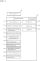
- FIG. 2 is a functional block diagram of the point cloud data processing device 100.
- the point cloud data processing device 100 includes: various function units including a data acquiring unit 111, a trajectory calculating unit 112, a primary point cloud data generating unit 113, an extraction region setting unit 114, an extracted point cloud data generating unit 115, a measurement ground control point detecting unit 116, a measurement ground control point adjusting unit 117, a reciprocation completion determining unit 118, a noise determining unit 119, and a resultant point cloud data generating unit 120; a storage unit 130; a display unit 140; and an input unit 150.
- various function units including a data acquiring unit 111, a trajectory calculating unit 112, a primary point cloud data generating unit 113, an extraction region setting unit 114, an extracted point cloud data generating unit 115, a measurement ground control point detecting unit 116, a measurement ground control point adjusting unit 117, a reciprocation completion determining unit 118, a noise determining unit 119,
- the respective function units implement respective functions by executing programs by the CPU.
- the programs to implement the functions of the respective function units may be stored in a storage medium such as a magnetic disc, a flexible disc, an optical disc, a compact disc, a Blu-ray (registered trademark) disc, a DVD, or the like.
- the trajectory calculating unit 112 receives satellite positioning data and inertial positioning data from the storage unit 130, and calculates a trajectory of the measuring device 20 in a plane rectangular coordinate system by processing using a Kalman filter.
- the primary point cloud data generating unit 113 generates primary point cloud data in a plane rectangular coordinate system by using the measurement point cloud data and the calculated trajectory point data.
- the resultant point cloud data generating unit 120 deletes data determined as noise by the noise determining unit 119, generates resultant point cloud data by synthesizing point cloud data for the forward route and the return route, displays the data on the display unit 140, and stores the data in the storage unit 130.
- the storage unit 130 stores measurement data, data calculated in the respective function units, and various programs and settings for making the data processing device 100 implement the functions.
- the storage unit 130 is realized by a main storage device and an auxiliary storage device, however, may be realized only by a main storage device or only by an auxiliary storage device.
- the display unit 140 displays extracted point cloud data and resultant point cloud data, etc.
- the display unit 140 is realized by a display device.
- the input unit 150 is a user interface for inputting various commands for, for example, the start of processing from a user.
- An example of the input unit 150 may include a keyboard, a mouse, etc.
- measurement data acquired by the measuring device 20 through reciprocation on a predetermined measurement route is used, and description is given on the assumption that an analysis target is ground control points 40 set at predetermined intervals on a road 30 on the measurement route as illustrated in FIG. 3 .
- Each ground control point 40 is provided with a reflection sheets, and the like.
- the ground control points 40 are measured by a total station and their coordinates are made known in advance.
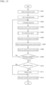
- FIG. 4 is a flowchart of the point cloud data processing method.
- the trajectory calculating unit 112 receives satellite positioning data and inertial positioning data for one route from the storage unit 130, and by processing using a Kalman filter, calculates a trajectory in a plane rectangular coordinate system.
- Step S102 the primary point cloud data generating unit 113 converts measurement point cloud data relating to the same route into plane rectangular coordinate system data by use of the trajectory calculated in Step S101 to generate primary point cloud data of the entire circumference.
- Detection and designation of ground control points may be realized by a configuration made such that a user can recognize portions having high reflection intensities and specific shapes as ground control points in the extracted point cloud data displayed on the display unit and can select the points in order with a mouse pointer, etc.
- Alternatively, another configuration is also possible in which ground control points can be automatically extracted from point cloud data based on reflection intensities and shapes.
- Step S106 the measurement ground control point adjusting unit 117 re-calculates a trajectory based on the detected measurement ground control points and known ground control point coordinates. Based on the re-calculated trajectory, the measurement ground control point adjusting unit 117 generates adjusted point cloud data.
- Step S107 the reciprocation completion determining unit 118 determines whether the generation of adjusted point cloud data has been completed for both of the forward route and the return route of the measurement route.
- Step S107 when the generation is completed for both routes (Yes), in Step S108, the noise determining unit 119 compares the adjusted point cloud data for forward route and the return route to determine whether there is data included only in one route.
- Step S108 when there is data included only in one route (Yes), the noise determining unit 119 determines the data included only in one route as noise, and in Step S109, deletes this noise point cloud data. Then, the processing shifts to Step S110.
- Step S108 when there is no data included only in one route (No), the noise determining unit 119 determines the adjusted point cloud data in question as data without noise, and the processing shifts to Step S110.
- Step S110 the resultant point cloud data generating unit 120 synthesizes adjusted point cloud data from which noise was deleted in S109 or adjusted point cloud data determined as data without noise in Step S108 for the forward route and the return route to generate resultant point cloud data.
- the resultant point cloud data is then output to the display unit 140 and stored in the storage unit 130, and the processing is ended.
- FIG. 5 is a detailed flowchart of Step S103.
- Step S201 the extraction region setting unit 114 sets an arbitrary vertical plane V i orthogonal to the trajectory T of the measuring device 20 as illustrated in FIG. 6A.
- FIG. 6A illustrates the trajectory calculated in Step S101 represented in a plane rectangular coordinate system.
- the measuring device 20 is assumed to have moved eastward on the E axis.
- Step S202 on the vertical plane V i , based on a perpendicular L i drawn down to the horizontal plane H from an intersection P i of the trajectory T and the vertical plane V i , the extraction region setting unit 114 designates an extraction angle range ⁇ as - ⁇ 1 ⁇ ⁇ ⁇ + ⁇ 2 around the intersection P i .
- FIG. 6B is a diagram of an arbitrary vertical plane V i orthogonal to the trajectory T as viewed in the moving direction of the measuring device 20.
- Values of the extraction angular widths ⁇ 1 and ⁇ 2 are set in advance.
- Step S203 the extraction region setting unit 114 sets an extraction reference distance l.
- the extraction reference distance l is set as a distance in the vertical direction from the intersection P i of the trajectory T and an arbitrary vertical plane V i on the vertical plane V i as illustrated in FIG. 7A .
- a value of the extraction reference distance l may be set in advance. For example, the distance from a road surface to the trajectory T is estimated to be substantially equal to a height h of the measuring device 20.
- the height h of the measuring device 20 from the road surface is known. Therefore, as illustrated in FIG. 7B , the height h of the measuring device 20 can be set as the extraction reference distance l.
- a structural object measured in the vertically downward direction is mainly the road 30, so that setting the height h of the measuring device 20 as the extraction reference distance l enables easy and proper setting of the extraction reference distance l.
- Step S204 by using extraction widths d 1 and d 2 determined in advance, an extraction distance range D is designated as l-d 1 ⁇ D ⁇ 1+d 2 from an intersection P i with the trajectory.
- the extraction distance widths d 1 and d 2 may be equal to each other, or different from each other.
- Step S205 as illustrated in FIG. 7A , the extraction region setting unit 114 identifies a trapezoid two-dimensional figure S on the vertical plane V i by using the designated extraction angle range ⁇ and extraction distance range D.
- Step S206 as illustrated in FIG. 7C , the extraction region setting unit 114 sets a region obtained by extending the two-dimensional figure S along the trajectory, as an extraction region A, and the processing shifts to Step S104.
- FIGS. 8A and 8B An example of extracted point cloud data extracted in this way is illustrated in FIGS. 8A and 8B.
- FIG. 8A illustrates primary point cloud data before extraction processing
- FIG. 8B is a bird's-eye view of the same route, illustrating point cloud data after extraction processing.
- FIG. 9A is a plan view enlarging the white-line quadrangular portion illustrated in FIG. 8A of the same primary point cloud data as in FIG. 8A
- FIG. 9B is a view in the arrow direction in FIG. 9A as viewed from a point of view on the road.
- the road 30 is covered by point cloud data based on the tree 50 and other structural objects. Therefore, it is difficult to visually identify the measurement ground control points 41 from the displayed point cloud data.
- the measurement ground control points 41 can be detected. However, magnification and a change in display region need to be repeated for detection, so that the detection operation becomes troublesome.
- point cloud data on an analysis target can be easily extracted from point cloud data acquired over the entire circumference of the measuring device for a measurement route.
- the point cloud data processing device 100 may be configured as a point cloud data extracting device that does not include the measurement ground control point detecting unit 116, the measurement ground control point adjusting unit 117, the reciprocation completion determining unit 118, the noise determining unit 119, and the resultant point cloud data generating unit 120, and executes only the processing of Steps S101 to S104.
- an analysis target is given by assuming an analysis target as ground control points 40 set on the road 30.
- an analysis target not only the ground control points 40 but also a road surface shape of the road 30 or a structural object installed near the road surface, etc. can be used as an analysis target.
- the setting of the extraction reference distance l in Step S203 may be not only setting in advance but also be automatic setting as follows.
- a furthest point Q x from the trajectory T is identified, and a distance between the point Q x and the trajectory T may be set as the extraction reference distance l.
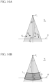
- FIG. 10A is a view in the traveling direction from a vertical plane V 0 at the starting point P 0 of the trajectory T.
- the shortest distances from the respective points Q 1 , Q 2 , Q 3 ,... to the trajectory T are calculated and compared with each other, and a point having the longest distance is identified as the furthest point Q x . Then, a shortest distance between the point Q x and the trajectory T is set as the extraction reference distance l.
- a structural object measured in the vertically downward direction is mainly the road 30, and there is a high possibility that the furthest point Q x is present on a road surface of the road 30 or in the surroundings of the road surface. Therefore, by designating a range with predetermined extraction distance widths d 1 and d 2 upward and downward from the point Q x set as a reference as the extraction distance range D, an extraction region for accurate extraction of point cloud data based on structural objects around the road surface of the road 30 can be set.
- a lowest point may be identified, simply. This is because the lowest point is considered to be present near the furthest point Q x , and when considering a measurement of the road surface, the road surface is highly likely to include the lowest point.
- the furthest point Q x matches the lowest point. In this way, even by designating a range with predetermined extraction distance widths d 1 and d 2 upward and downward from the lowest point set as a reference, an extraction region for accurate extraction of point cloud data based on structural objects around the road surface of the road 30 can be set.
- the extraction reference distance l may be set as follows.
- the extraction region setting unit 114 identifies a cube C x whose shortest distance from the trajectory T is the longest among the cubes including points at densities not less than the predetermined value. A center of this cube is identified as a furthest point Q x from the trajectory T.
- the shortest distance between the point Q x and the trajectory T that is, a distance between the point Q x and the intersection P x on the vertical plane V x passing through the point Q x illustrated in FIG. 11B , is calculated as the extraction reference distance l.
- the two-dimensional figure identified by the extraction angle range ⁇ and the extraction distance range D may be not a trapezoid as described above but an annular arc shape S 1 whose width is the extraction distance range D and whose central angle is the extraction angle range ⁇ as illustrated in FIG. 10B .
- the point cloud data processing device 100 may be configured to be capable of switching an extraction mode according to a position of an analysis target, etc.
- FIG. 12 is a functional block diagram of a point cloud data processing device 100a according to this modification.
- the point cloud data processing device 100a is a personal computer including the same hardware as in the point cloud data processing device 100. However, the point cloud data processing device 100a includes an extraction mode selecting unit 221 and a selected mode setting unit 222 in addition to the point cloud data processing device 100.
- the extraction mode selecting unit 121 displays display for a user to select an extraction mode on the display unit 140. Selection of an extraction mode by a user by using the input unit 150 is enabled.
- the selected mode setting unit 122 sets parameters (extraction angular widths ⁇ 1 and ⁇ 2 , an extraction reference distance l, and extraction distance widths d 1 and d 2 ) corresponding to a selected extraction mode.
- FIG. 13 is a flowchart of point cloud data processing of the point cloud data processing device 200.
- the extraction mode setting unit 121 displays a menu window 80 for selecting an extraction mode on the display unit 140 as illustrated in FIG. 14 , and a user selects an extraction mode.
- the road surface 1 mode corresponds to a case where the road is a one-lane road and ground control points are set at the center of the road.
- the road surface 2 mode corresponds to a case where the road is a two-lane road and ground control points are set on the center line.
- a user selects arbitrary setting mode, the user can set the extraction angular widths ⁇ 1 and ⁇ 2 , the extraction reference distance l, and the extraction distance widths d 1 and d 2 by inputting arbitrary values.
- the configuration is made such that a user can select a mode by turning a radio button on with the mouse pointer 81.
- FIG. 14 illustrates a state where the mode for the road surface 1 is selected.
- the extraction angular widths ⁇ 1 and ⁇ 2 , the extraction reference distance l, and the extraction distance widths d 1 and d 2 corresponding to each extraction mode as illustrated in Table 1 are set in advance, and are stored in the form of, for example, a table, etc.
- Step S402 When a user selects an extraction mode, the processing shifts to Step S402, and the selected mode setting unit 122 sets the extraction angular widths ⁇ 1 and ⁇ 2 , the extraction reference distance l, and the extraction distance widths d 1 an d 2 set for each extraction mode, respectively.
- Step S403 the same processing as in Steps S101 to S110 is executed based on the values set in Step S402.
- configuring a single data processing device to be capable of executing a plurality of extraction modes enables easy setting of proper extraction conditions according to positions, etc., of ground control points on a road.
Landscapes
- Engineering & Computer Science (AREA)
- Physics & Mathematics (AREA)
- General Physics & Mathematics (AREA)
- Radar, Positioning & Navigation (AREA)
- Remote Sensing (AREA)
- Theoretical Computer Science (AREA)
- Multimedia (AREA)
- Computer Vision & Pattern Recognition (AREA)
- Computer Networks & Wireless Communication (AREA)
- Signal Processing (AREA)
- Length Measuring Devices With Unspecified Measuring Means (AREA)
- Length Measuring Devices By Optical Means (AREA)
- Optical Radar Systems And Details Thereof (AREA)
Description
- The present disclosure relates to a point cloud data processing method and a point cloud data processing device.
- Conventionally, an MMS (Mobile Mapping System) has been known for acquiring three-dimensional positional information of the peripheries of a road, such as building and road shapes, signs, and guardrails, etc., highly accurately and efficiently while moving. The MMS is configured by installing a measuring device including a GNSS (Global Navigation Satellite System), an antenna, an IMU (Inertial Measuring Unit), a camera, a laser scanner, etc., in a mobile body such as a vehicle.
- Such systems are known from
US 2019/078880 A1 andUS 2009/232388 A1 . - An MMS is a system intended to execute post-processing of data. Therefore, first, while traveling in a measurement section on a target road by vehicle, the MMS acquires data on its own position based on a GNSS navigation signal (hereinafter, referred to as "satellite positioning data"), three-dimensional acceleration and angular velocity data obtained by the IMU (hereinafter, referred to as "inertial positioning data"), and measurement data at each point of scanning light by the laser scanner (hereinafter, referred to as "measurement point cloud data"), and next, calculates a trajectory of the vehicle on the basis of the satellite positioning data and the inertial positioning data, and synthesizes the calculated trajectory of the vehicle and the point cloud data to generate three-dimensional point cloud data as a result.
- The laser scanner acquires a point cloud over the entire circumference, so that acquired point cloud data includes a large number of point data due to structural objects other than an analysis target. Therefore, in order to analyze an analysis target, a portion including the analysis target needs to be manually extracted, and the extraction operation is troublesome.
- In order to solve this problem,
Patent Literature 1 discloses a point cloud data processing method in which a columnar region and a parallelepiped region disposed at predetermined positions on a lower side of the trajectory are set as extraction regions, and point data belonging to these extraction regions are extracted as target point cloud data. - However, to perform an analysis of various structural objects, a new point cloud data processing method for extracting target point cloud data from entire circumference point cloud data has been required.
-
Patent Literature 1 International PublicationWO 2018/159690 - The present invention was made in view of the above-described circumstances, and an object thereof is to provide a point cloud data processing method and a point cloud data processing device capable of easily extracting an analysis target from entire circumference point cloud data acquired by a measuring device that is moving along a measurement route.
- In order to achieve the above-described object, a point cloud data processing method according to
claim 1 is disclosed. Further refinements of said method are disclosed in claims 2-6. - A point cloud data processing device according to claim 7 is also disclosed.
- With the point cloud data processing method and the point cloud data processing device as claimed, an analysis target can be easily extracted from entire circumference point cloud data acquired by a measuring device that is moving along a measurement route.
-
-
FIG. 1A is a view illustrating an outline of a measuring device that measures measurement data for a point cloud data processing method, andFIG. 1B is a view schematically illustrating a state of measurement by the measuring device. -
FIG. 2 is a functional block diagram of a point cloud data processing device that executes the point cloud data processing method according to the present invention. -
FIG. 3 is a view illustrating an example of a measurement route to be measured by the measuring device. -
FIG. 4 is a flowchart of point cloud data generation processing in the point cloud data processing method. -
FIG. 5 is a flowchart of extraction region setting processing in the same point cloud data processing method. -
FIGS. 6A and 6B are diagrams describing an extraction region setting method in the same point cloud data processing method. -
FIGS. 7A, 7B, and 7C are diagrams describing an extraction region setting method in the same point cloud data processing method. -
FIG. 8A illustrates entire circumference point cloud data before extraction processing by the same point cloud data processing method, andFIG. 8B illustrates extracted point cloud data after extraction processing by the same method. -
FIGS. 9A and 9B are views of the point cloud data inFIG. 8A as viewed from different directions. -
FIGS. 10A and 10B are diagrams illustrating a modification of the extraction region setting processing in the same point cloud data processing method. -
FIG. 11 is a diagram illustrating another modification of the extraction region setting processing in the same point cloud data processing method. -
FIG. 12 is a functional block diagram of still another modification of the point cloud data processing device that executes the same point cloud data processing method. -
FIG. 13 is a flowchart of point cloud data processing by the point cloud data processing device. -
FIG. 14 is a view illustrating an extraction mode selection screen in the same point cloud data processing device. - Hereinafter, a preferred embodiment of the present invention will be described with reference to the drawings, however, the present invention is not limited to this. In the following description of the embodiment, the same components are provided with the same reference signs, the same components are provided with the same names, and overlapping description is omitted as appropriate.
- A point cloud data processing device is a device to execute post-processing of measurement data acquired by, for example, a
measuring device 20 illustrated inFIG. 1 . First, themeasuring device 20 will be described. - The
measuring device 20 is a so-called MMS (Mobile Mapping System). Themeasuring device 20 includes aGNSS device 21, an IMU 22, acamera 23, alaser scanner 24, arotary encoder 25, and asynchronization control device 26, installed in avehicle 27. - The GNSS
device 21 is a receiving device that receives a navigation signal from anavigation satellite 28 such as a GNSS satellite. Based on the navigation signal, the GNSSdevice 21 acquires satellite positioning data, that is, a plan position and an altitude of themeasuring device 20. For example, theGNSS device 21 acquires coordinates of themeasuring device 20 at intervals of ten times/second. - The IMU 22 is an inertial measuring device, includes a three axis gyroscope and a 3-directional accelerometer, and acquires inertial positioning data.
- The
camera 23 is a 360-degree camera consisting of a plurality of cameras, and shoots a video of the entire circumference (2π space) including an upper direction. Although not described herein, video image data shot by thecamera 23 is used for construction of three-dimensional information of the surroundings in combination with point cloud data measured by thelaser scanner 24. - Exterior orientation elements (positions and postures) of the
camera 23 and thelaser scanner 24 with respect to the measuring device 20 (the position of the IMU) are measured in advance, and such information is known. - As illustrated in
FIG. 1B , thelaser scanner 24 spirally irradiates a scanning light La onto the entire circumference (2π space), and receives a reflected light Lb (FIG. 1B ) from a structural object such as aroad 30, a building, and a tree. Based on a time from emission of the scanning light La until reception of the reflected light Lb, thelaser scanner 24 obtains a three-dimensional position of each reflection point, to acquire point cloud data over the entire circumference of thelaser scanner 24. - Along with movement of the
vehicle 27, thelaser scanner 24 acquires measurement point cloud data as the entire circumference point cloud data of ascanning range 32 along a measurement route. - The
laser scanner 24 is one in number. However, the number is not limited to this. The measuringdevice 20 may include a plurality oflaser scanners 24 such as three or five. When the number oflaser scanners 24 is increased, the point cloud density increases, and shadow portions can be minimized, so that a measurement with higher accuracy can be made. - The
rotary encoder 25 is attached to awheel 29 of thevehicle 27, and acquires vehicle moving distance data from a rotation speed and a rotation angle of thewheel 29. - The
synchronization control device 26 is connected via cables, etc., or wirelessly to theGNSS device 21, theIMU 22, thecamera 23, thelaser scanner 24, and therotary encoder 25. - The
synchronization control device 26 synchronizes a time of inertial positioning data acquisition by theIMU 22, a time of image data acquisition by thecamera 23, a time of point cloud data acquisition by thelaser scanner 24, and a time of acquisition of moving distance data of thewheel 29 by therotary encoder 25. - While moving along a measurement route, the measuring
device 20 acquires satellite positioning data, inertial positioning data, measurement point cloud data, and moving distance data respectively by theGNSS device 21, theIMU 22, thecamera 23, thelaser scanner 24, and therotary encoder 25. Hereinafter, these data are collectively referred to as "measurement data". - Hereinafter, a point cloud data generating method and a point cloud
data processing device 100 according to the present invention will be described. The point clouddata processing device 100 generates three-dimensional point cloud data (resultant point cloud data) around a measurement route by using measurement data acquired by the measuringdevice 20. - The point cloud
data processing device 100 is a so-called personal computer. The point clouddata processing device 100 includes hardware such as a CPU (Central Processing Unit) as a processor, a RAM (Random Access Memory) and a ROM (Read-Only Memory) as a main storage device, and a HDD (Hard Disk Drive) as an auxiliary storage device, and a liquid crystal display as a display device, etc. - The point cloud
data processing device 100 is configured to be connectable to theGNSS device 21, theIMU 22, thecamera 23, thelaser scanner 24, and therotary encoder 25 via thesynchronization control device 26. The point clouddata processing device 100 may be located outside the vehicle or may be located inside the vehicle. In the present description, for the sake of convenience, the point cloud data processing device is assumed to be located outside the vehicle. -
FIG. 2 is a functional block diagram of the point clouddata processing device 100. The point clouddata processing device 100 includes: various function units including adata acquiring unit 111, atrajectory calculating unit 112, a primary point clouddata generating unit 113, an extractionregion setting unit 114, an extracted point clouddata generating unit 115, a measurement ground controlpoint detecting unit 116, a measurement ground controlpoint adjusting unit 117, a reciprocationcompletion determining unit 118, anoise determining unit 119, and a resultant point clouddata generating unit 120; astorage unit 130; adisplay unit 140; and aninput unit 150. - The respective function units implement respective functions by executing programs by the CPU. The programs to implement the functions of the respective function units may be stored in a storage medium such as a magnetic disc, a flexible disc, an optical disc, a compact disc, a Blu-ray (registered trademark) disc, a DVD, or the like.
- The
data acquiring unit 111 accepts measurement data via an input interface (not illustrated) and stores the measurement data in thestorage unit 130. - The input interface is a port to be connected to the
synchronization control device 26. The input interface is, for example, a USB (Universal Serial Bus) terminal. Alternatively, the input interface may be a port to be connected to a LAN (Local Area Network). - The
trajectory calculating unit 112 receives satellite positioning data and inertial positioning data from thestorage unit 130, and calculates a trajectory of the measuringdevice 20 in a plane rectangular coordinate system by processing using a Kalman filter. - As described above, a positional relationship between the
laser scanner 24 and the measuring device 20 (IMU device) is known, and associated with each other. That is, in the present description, "trajectory of the measuringdevice 20" is associated with "trajectory of the center of thelaser scanner 24." - The primary point cloud
data generating unit 113 generates primary point cloud data in a plane rectangular coordinate system by using the measurement point cloud data and the calculated trajectory point data. - Based on respective trajectory points acquired by the
trajectory calculating unit 112, the extractionregion setting unit 114 sets an extraction angle range and an extraction distance range to set an extraction region. - The extracted point cloud
data generating unit 115 generates extracted point cloud data by extracting point cloud data disposed in the region set by the extractionregion setting unit 114 from the primary point cloud data. And, outputs the extracted point cloud data to thedisplay unit 140, and stores the extracted point cloud data in thestorage unit 130. - The measurement ground control
point detecting unit 116 detects measurement ground control points 41 from the extracted point cloud data displayed on thedisplay unit 140. - The measurement ground control
point adjusting unit 117 re-calculates a trajectory based on the measurement ground control points 41 detected by the measurement ground controlpoint detecting unit 116 and known ground control point coordinates. Then, based on the re-calculated trajectory and the extracted point cloud data, the measurement ground controlpoint adjusting unit 117 generates adjusting point cloud data. - The reciprocation
completion determining unit 118 determines whether the generation of adjusted point cloud data has been completed for both of a forward route and a return route of the measurement route. - The
noise determination unit 119 compares adjusted point cloud data for the forward route and the return route of the measurement route, and determines data included in only one route of the forward and return route as noise. - The resultant point cloud
data generating unit 120 deletes data determined as noise by thenoise determining unit 119, generates resultant point cloud data by synthesizing point cloud data for the forward route and the return route, displays the data on thedisplay unit 140, and stores the data in thestorage unit 130. - The
storage unit 130 stores measurement data, data calculated in the respective function units, and various programs and settings for making thedata processing device 100 implement the functions. Thestorage unit 130 is realized by a main storage device and an auxiliary storage device, however, may be realized only by a main storage device or only by an auxiliary storage device. - The
display unit 140 displays extracted point cloud data and resultant point cloud data, etc. Thedisplay unit 140 is realized by a display device. - The
input unit 150 is a user interface for inputting various commands for, for example, the start of processing from a user. An example of theinput unit 150 may include a keyboard, a mouse, etc. - Next, a point cloud data processing method according to the invention is described.
- As a detailed example, measurement data acquired by the measuring
device 20 through reciprocation on a predetermined measurement route is used, and description is given on the assumption that an analysis target is ground control points 40 set at predetermined intervals on aroad 30 on the measurement route as illustrated inFIG. 3 . Eachground control point 40 is provided with a reflection sheets, and the like. The ground control points 40 are measured by a total station and their coordinates are made known in advance. -
FIG. 4 is a flowchart of the point cloud data processing method. When the processing is started, in Step S101, thetrajectory calculating unit 112 receives satellite positioning data and inertial positioning data for one route from thestorage unit 130, and by processing using a Kalman filter, calculates a trajectory in a plane rectangular coordinate system. - Next, in Step S102, the primary point cloud
data generating unit 113 converts measurement point cloud data relating to the same route into plane rectangular coordinate system data by use of the trajectory calculated in Step S101 to generate primary point cloud data of the entire circumference. - Next, in Step S103, the extraction
region setting unit 114 sets an extraction angle range and an extraction distance range to set an extraction region. Details of setting of the extraction angle range and setting of the extraction distance range will be described later. - Next, in Step S104, the extracted point cloud
data generating unit 115 extracts point cloud data in the region determined by the extractionregion setting unit 114 from the primary point cloud data, to generate extracted point cloud data. And, the extracted point clouddata generating unit 115 displays the extracted point cloud data on thedisplay unit 140, and stores the extracted point cloud data in thestorage unit 130. - Next, in Step S105, the measurement ground control
point detecting unit 116 detects points or regions with high reflection intensity from the extracted point cloud data displayed on thedisplay unit 140, and designates the points or regions as ground control points 40. On the ground control points 40 set on the road, reflection sheets or the like are provided, so that the measurement ground control points 41 in the point cloud data appear as points or regions with high reflection intensities. - Detection and designation of ground control points may be realized by a configuration made such that a user can recognize portions having high reflection intensities and specific shapes as ground control points in the extracted point cloud data displayed on the display unit and can select the points in order with a mouse pointer, etc. Alternatively, another configuration is also possible in which ground control points can be automatically extracted from point cloud data based on reflection intensities and shapes.
- Next, in Step S106, the measurement ground control
point adjusting unit 117 re-calculates a trajectory based on the detected measurement ground control points and known ground control point coordinates. Based on the re-calculated trajectory, the measurement ground controlpoint adjusting unit 117 generates adjusted point cloud data. - Next, in Step S107, the reciprocation
completion determining unit 118 determines whether the generation of adjusted point cloud data has been completed for both of the forward route and the return route of the measurement route. - When the generation has been completed only for one route (for example, the forward route) (No), the processing returns to Step S101, and the processing in Steps S101 to S107 is repeated for the other route (for example, the return route).
- On the other hand, in Step S107, when the generation is completed for both routes (Yes), in Step S108, the
noise determining unit 119 compares the adjusted point cloud data for forward route and the return route to determine whether there is data included only in one route. - In Step S108, when there is data included only in one route (Yes), the
noise determining unit 119 determines the data included only in one route as noise, and in Step S109, deletes this noise point cloud data. Then, the processing shifts to Step S110. - On the other hand, in Step S108, when there is no data included only in one route (No), the
noise determining unit 119 determines the adjusted point cloud data in question as data without noise, and the processing shifts to Step S110. - Then, in Step S110, the resultant point cloud
data generating unit 120 synthesizes adjusted point cloud data from which noise was deleted in S109 or adjusted point cloud data determined as data without noise in Step S108 for the forward route and the return route to generate resultant point cloud data. The resultant point cloud data is then output to thedisplay unit 140 and stored in thestorage unit 130, and the processing is ended. - Next, the setting of an extraction region in Step S103 is described with reference to
FIGS. 5 to 7 .FIG. 5 is a detailed flowchart of Step S103. - When the setting of an extraction region is started, in Step S201, the extraction
region setting unit 114 sets an arbitrary vertical plane Vi orthogonal to the trajectory T of the measuringdevice 20 as illustrated inFIG. 6A. FIG. 6A illustrates the trajectory calculated in Step S101 represented in a plane rectangular coordinate system. For the sake of convenience, the measuringdevice 20 is assumed to have moved eastward on the E axis. - Next, as illustrated in
FIG. 6B , in Step S202, on the vertical plane Vi, based on a perpendicular Li drawn down to the horizontal plane H from an intersection Pi of the trajectory T and the vertical plane Vi, the extractionregion setting unit 114 designates an extraction angle range Θ as -θ1 ≤ Θ ≤ +θ2 around the intersection Pi.FIG. 6B is a diagram of an arbitrary vertical plane Vi orthogonal to the trajectory T as viewed in the moving direction of the measuringdevice 20. - Values of the extraction angular widths θ1 and θ2 are set in advance. Generally, the ground control points 40 are set at the center of the road as illustrated in
FIG. 3 or at predetermined positions such as positions on the road shoulder. Therefore, the values of the extraction angular widths θ1 and θ2 can be predicted to some extent from, for example, a relationship between the height of the intersection P from the road and a road width or set position. Based on this prediction, for example, setting is made such that, when the ground control points are set at the center of a one-lane road, θ1 = θ2 = 40°, and when the ground control points are set, for example, on the center line of a two-lane road, θ1 = 60° and θ2 = 40°. - Next, in Step S203, the extraction
region setting unit 114 sets an extraction reference distance l. The extraction reference distance l is set as a distance in the vertical direction from the intersection Pi of the trajectory T and an arbitrary vertical plane Vi on the vertical plane Vi as illustrated inFIG. 7A . - A value of the extraction reference distance l may be set in advance. For example, the distance from a road surface to the trajectory T is estimated to be substantially equal to a height h of the measuring
device 20. The height h of the measuringdevice 20 from the road surface is known. Therefore, as illustrated inFIG. 7B , the height h of the measuringdevice 20 can be set as the extraction reference distance l. - In a measurement using the measuring
device 20, a structural object measured in the vertically downward direction is mainly theroad 30, so that setting the height h of the measuringdevice 20 as the extraction reference distance l enables easy and proper setting of the extraction reference distance l. - Next, in Step S204, by using extraction widths d1 and d2 determined in advance, an extraction distance range D is designated as l-d1 ≤ D ≤ 1+d2 from an intersection Pi with the trajectory.
- The extraction distance widths d1 and d2 can be set such that d1, d2 = 30 cm when it is desired to extract, for example, points around a road as in this e. The extraction distance widths d1 and d2 may be equal to each other, or different from each other.
- Next, in Step S205, as illustrated in
FIG. 7A , the extractionregion setting unit 114 identifies a trapezoid two-dimensional figure S on the vertical plane Vi by using the designated extraction angle range Θ and extraction distance range D. - Next, in Step S206, as illustrated in
FIG. 7C , the extractionregion setting unit 114 sets a region obtained by extending the two-dimensional figure S along the trajectory, as an extraction region A, and the processing shifts to Step S104. - An example of extracted point cloud data extracted in this way is illustrated in
FIGS. 8A and 8B. FIG. 8A illustrates primary point cloud data before extraction processing, andFIG. 8B is a bird's-eye view of the same route, illustrating point cloud data after extraction processing.FIG. 9A is a plan view enlarging the white-line quadrangular portion illustrated inFIG. 8A of the same primary point cloud data as inFIG. 8A , andFIG. 9B is a view in the arrow direction inFIG. 9A as viewed from a point of view on the road. - As illustrated in
FIG. 8A , in the primary point cloud data before the extraction processing, theroad 30 is covered by point cloud data based on thetree 50 and other structural objects. Therefore, it is difficult to visually identify the measurement ground control points 41 from the displayed point cloud data. By changing the display direction as inFIG. 9B , the measurement ground control points 41 can be detected. However, magnification and a change in display region need to be repeated for detection, so that the detection operation becomes troublesome. - On the other hand, as illustrated in
FIG. 8B , after the extraction processing, theroad 30 and the measurement ground control points 41 can be easily detected. - In this way, by the point cloud data generating method, point cloud data on an analysis target can be easily extracted from point cloud data acquired over the entire circumference of the measuring device for a measurement route.
- When structural objects such as trees and buildings are present over the traveling route of the measuring
device 20, it is difficult to detect ground control points from primary point cloud data, as inFIG. 8A . Such situation means that the area over the measuringdevice 20 is shielded at the time of measurement. In this case, a reception condition of theGNSS device 21 deteriorates, and a trajectory error easily becomes large. - Therefore, in order to acquire highly accurate three-dimensional point cloud data, it is important to adjust the trajectory and the point cloud data with the measurement ground control points 41. In this way, easy detection of ground control points by setting the analysis target as the ground control points and extracting point cloud data makes easier adjustments of trajectory and point cloud data, and this is particularly advantageous.
- On the other hand, the point cloud
data processing device 100 may be configured as a point cloud data extracting device that does not include the measurement ground controlpoint detecting unit 116, the measurement ground controlpoint adjusting unit 117, the reciprocationcompletion determining unit 118, thenoise determining unit 119, and the resultant point clouddata generating unit 120, and executes only the processing of Steps S101 to S104. - In this case, as primary point cloud data, entire circumference point cloud data in various stages such as point cloud data adjusted by using a trajectory that has already been adjusted, can be used.
- In this embodiment, a description is given by assuming an analysis target as ground control points 40 set on the
road 30. However, in this method, not only the ground control points 40 but also a road surface shape of theroad 30 or a structural object installed near the road surface, etc. can be used as an analysis target. - The setting of the extraction reference distance l in Step S203 may be not only setting in advance but also be automatic setting as follows. As an example, as illustrated in
FIG. 10A , in point data included in the extraction angle range Θ, a furthest point Qx from the trajectory T is identified, and a distance between the point Qx and the trajectory T may be set as the extraction reference distance l.FIG. 10A is a view in the traveling direction from a vertical plane V0 at the starting point P0 of the trajectory T. - In this case, simply, the shortest distances from the respective points Q1, Q2, Q3,... to the trajectory T are calculated and compared with each other, and a point having the longest distance is identified as the furthest point Qx. Then, a shortest distance between the point Qx and the trajectory T is set as the extraction reference distance l.
- In a measurement using the measuring
device 20, a structural object measured in the vertically downward direction is mainly theroad 30, and there is a high possibility that the furthest point Qx is present on a road surface of theroad 30 or in the surroundings of the road surface. Therefore, by designating a range with predetermined extraction distance widths d1 and d2 upward and downward from the point Qx set as a reference as the extraction distance range D, an extraction region for accurate extraction of point cloud data based on structural objects around the road surface of theroad 30 can be set. - Alternatively, as the furthest point Qx, a lowest point may be identified, simply. This is because the lowest point is considered to be present near the furthest point Qx, and when considering a measurement of the road surface, the road surface is highly likely to include the lowest point. In
FIG. 10A , the furthest point Qx matches the lowest point. In this way, even by designating a range with predetermined extraction distance widths d1 and d2 upward and downward from the lowest point set as a reference, an extraction region for accurate extraction of point cloud data based on structural objects around the road surface of theroad 30 can be set. - Alternatively, as another example, the extraction reference distance l may be set as follows.
- First, as illustrated in
FIG. 11A , in the extraction angle range Θ in the plane rectangular coordinate system, cubes C1, C2,... with predetermined dimensions are stacked, and cubes each including points whose density is not less than a predetermined value are extracted. InFIG. 11A , shaded portions are cubes including points at densities not less than the predetermined value. - Next, the extraction
region setting unit 114 identifies a cube Cx whose shortest distance from the trajectory T is the longest among the cubes including points at densities not less than the predetermined value. A center of this cube is identified as a furthest point Qx from the trajectory T. - Next, the shortest distance between the point Qx and the trajectory T, that is, a distance between the point Qx and the intersection Px on the vertical plane Vx passing through the point Qx illustrated in
FIG. 11B , is calculated as the extraction reference distance l. - In this way, by identifying the furthest point Qx by comparing the distances of the cubes having predetermined dimensions and including point data at a predetermined density or more from the trajectory, the influences of noise such as dust on the point data can be eliminated, so that a more accurate extraction reference distance l can be set.
- As a still another modification, the two-dimensional figure identified by the extraction angle range Θ and the extraction distance range D may be not a trapezoid as described above but an annular arc shape S1 whose width is the extraction distance range D and whose central angle is the extraction angle range Θ as illustrated in
FIG. 10B . - As a yet another modification, the point cloud
data processing device 100 according to the embodiment may be configured to be capable of switching an extraction mode according to a position of an analysis target, etc.FIG. 12 is a functional block diagram of a point clouddata processing device 100a according to this modification. - The point cloud
data processing device 100a is a personal computer including the same hardware as in the point clouddata processing device 100. However, the point clouddata processing device 100a includes an extraction mode selecting unit 221 and a selected mode setting unit 222 in addition to the point clouddata processing device 100. - The extraction
mode selecting unit 121 displays display for a user to select an extraction mode on thedisplay unit 140. Selection of an extraction mode by a user by using theinput unit 150 is enabled. - The selected mode setting unit 122 sets parameters (extraction angular widths θ1 and θ2, an extraction reference distance l, and extraction distance widths d1 and d2) corresponding to a selected extraction mode.
-
FIG. 13 is a flowchart of point cloud data processing of the point cloud data processing device 200. When the processing is started, first, in Step S401, the extractionmode setting unit 121 displays amenu window 80 for selecting an extraction mode on thedisplay unit 140 as illustrated inFIG. 14 , and a user selects an extraction mode. - In the example illustrated in
FIG. 14 , there are three modes for aroad surface 1, a road surface 2, and arbitrary setting on themenu window 80. Theroad surface 1 mode corresponds to a case where the road is a one-lane road and ground control points are set at the center of the road. The road surface 2 mode corresponds to a case where the road is a two-lane road and ground control points are set on the center line. When a user selects arbitrary setting mode, the user can set the extraction angular widths θ1 and θ2, the extraction reference distance l, and the extraction distance widths d1 and d2 by inputting arbitrary values. The configuration is made such that a user can select a mode by turning a radio button on with themouse pointer 81.FIG. 14 illustrates a state where the mode for theroad surface 1 is selected. - In the
storage unit 130, the extraction angular widths θ1 and θ2, the extraction reference distance l, and the extraction distance widths d1 and d2 corresponding to each extraction mode as illustrated in Table 1 are set in advance, and are stored in the form of, for example, a table, etc.[Table 1] Table 1 Extraction mode setting table Extraction mode θ1(°) θ2(°) 1(cm) d1(cm) d2(cm) Road surface 1 -40 40 200 30 30 Road surface 2 -60 60 200 30 30 Arbitrary setting Input value Input value Input value Input value Input value - When a user selects an extraction mode, the processing shifts to Step S402, and the selected mode setting unit 122 sets the extraction angular widths θ1 and θ2, the extraction reference distance l, and the extraction distance widths d1 an d2 set for each extraction mode, respectively.
- Next, the processing shifts to Step S403, and in subsequent Steps S403 to S412, the same processing as in Steps S101 to S110 is executed based on the values set in Step S402.
- In this way, configuring a single data processing device to be capable of executing a plurality of extraction modes enables easy setting of proper extraction conditions according to positions, etc., of ground control points on a road.
-
- 20
- Measuring device
- 100, 100a
- Point cloud data processing device
- 114
- Extraction region setting unit
- 121
- Extraction mode selecting unit
- 122
- Selected mode setting unit
- T
- Trajectory
- S
- Two-dimensional figure
- A
- Extraction region
Claims (7)
- A point cloud data processing method comprising the steps of:(a) calculating a trajectory (T) of an inertial measuring device (22) in a plane rectangular coordinate system as a trajectory of a measuring device (20) based on satellite positioning data and inertial positioning data acquired by the measuring device (20), the measuring device (20) including a 360-degree camera (23), a GNSS device (21) for acquiring satellite positioning data, an inertial measuring device (22) for acquiring inertial positioning data, a laser scanner (24) configured to scan the entire circumference to acquire three-dimensional point cloud data, a rotary encoder (25) for acquiring moving distance data of a moving body (27) from a rotation speed and a rotation angle of a wheel (29) of the moving body (27), and a synchronization control device (26) for synchronizing a time of inertial positioning data acquisition by the inertial measuring device (22), a time of image data acquisition by the camera (23), a time of point cloud data acquisition by the laser scanner (24), and a time of acquisition of moving distance data of the wheel (29) by the rotary encoder, the measuring device (20) installed on a moving body (27) moving along a measurement route;(b) converting the three-dimensional point cloud data relating to the same measurement route into plane rectangular coordinate system data by use of the trajectory (T) calculated in Step (a), to generate primary point cloud data of the entire circumference;(c) on a vertical plane (Vi) orthogonal to the trajectory (T),based on a perpendicular (Li) drawn down to the horizontal plane (H) from an intersection (Pi) of the trajectory (T) and the vertical plane (Vi), designating an extraction angle range (Θ) as
 (wherein θ1 and θ2 are extraction angular widths set in advance)around the intersection (Pi), andsetting an extraction reference distance (l) as a distance in a vertical direction from the intersection (Pi) to designate an extraction distance range (D) from an intersection (Pi) with the trajectory (T) as
 wherein d1 and d2 are extraction widths set in advance, to identify an area defined by the extraction angle range (Θ) and the extraction distance range (D) as a two-dimensional figure (S), andsetting a region obtained by extending the two-dimensional figure (S) along the trajectory (T) as an extraction region (A); and(d) extracting the primary point cloud data in the extraction region (A) as extracted point cloud data.
 - The point cloud data processing method according to Claim 1, wherein the two-dimensional figure (S) is, on the vertical plane (Vi), a trapezoid defined by two lines extending in a radial direction about the interception point (P) to define the extraction angle range (Θ) and two lines extending in a direction parallel to the horizontal plane (H) to define the extraction distance range (D) on the vertical line (Li).
- The point cloud data processing method according to Claim 1 or 2, whereinshortest distances from the respective points (Q1, Q2, Q3, ...) to the trajectory (T) are calculated and compared with each other,a point having the longest distance is identified as a furthest point (Qx), anda shortest distance between the furthest point (Qx) and the trajectory (T) is set as the extraction reference distance (l).
- The point cloud data processing method according to any of Claim 3, wherein
the two-dimensional figure (S) is, on the vertical plane (Vi), an annular arc shape defined by two lines extending in a radial direction about the interception point (Pi) to define the extraction angle range (Θ) and two arcs extending in a circumferential direction around the interception point (P) to define the extraction distance range (D) on the perpendicular (Li). - The point cloud data processing method according to Claim 4, whereinthe extraction reference distance (l) is set by sectioning the plane rectangular coordinate system so that cubes each having a predetermined size are continuous,extracting cubes each including point data whose density is not less than a predetermined value,identifying a cube whose shortest distance from the trajectory (T) among the cubes including points at densities not less than the predetermined value, andidentifying a center of a furthest cube (Cx) as a point (Qx) that is furthest from the trajectory (T).
- The point cloud data processing method according to any one of Claims 1 to 3, further comprising the steps of:(e) selecting one extraction mode from a plurality of extraction modes set in advance, each having the predetermined reference distance (l), the predetermined extraction distance widths (d1, d2) and the extraction angular widths (θ1, θ2),the step (c) being executed with the predetermined extraction reference distance(l), the predetermined extraction widths (d1, d2), and the extraction angular widths (θ1, θ2) in accordance with the selected one extraction mode.
- A point cloud data processing device comprising:a trajectory calculating unit (112) configured to calculate a trajectory (T) of an inertial measuring device (22) in a plane rectangular coordinate system as a trajectory of a measuring device (20) based on satellite positioning data and inertial positioning data acquired by the measuring device (20), the measuring device (20) including a 360-degree camera (23), a GNSS device (21) for acquiring satellite positioning data, an inertial measuring device (22) for acquiring inertial positioning data, a laser scanner (24) configured to scan the entire circumference to acquire three-dimensional point cloud data, a rotary encoder (25) for acquiring moving distance data of a moving body (27) from a rotation speed and a rotation angle of a wheel (29) of the moving body (27), and a synchronization control device (26) for synchronizing a time of inertial positioning data acquisition by the inertial measuring device (22), a time of image data acquisition by the camera (23), a time of point cloud data acquisition by the laser scanner (24), and a time of acquisition of moving distance data of the wheel (29) by the rotary encoder (25), the measuring device (20) installed on a moving body moving along a measurement route;a primary point cloud data generating unit (113) configured to convert the three-dimensional point cloud data relating to the same measurement route into plane rectangular coordinate system data by use of the trajectory (T), to generate primary point cloud data of the entire circumference,an extraction region setting unit (114) configured to on a vertical plane (Vi) orthogonal to the trajectory (T), based on a perpendicular (Li) drawn down to the horizontal plane (H) from an intersection (Pi) of the trajectory (T) and the vertical plane (Vi), designate an extraction angle range (Θ) as
 (wherein θ1 and θ2 are extraction angular widths set in advance) around the intersection (Pi), andset an extraction reference distance (l) as a distance in a vertical direction from the intersection (Pi) to designate an extraction distance range (D) from an intersection (Pi) with the trajectory (T) as
 wherein d1 and d2 are extraction widths set in advance, to identify an area defined by the extraction angle range (Θ) and the extraction distance range (D) as a two-dimensional figure (S), andset a region obtained by extending the two-dimensional figure (S) along the trajectory (T) as an extraction region (A), andan extracted point cloud data generating unit (115) configured to extract the primary point cloud data in the extraction region (A) as extracted point cloud data.
Applications Claiming Priority (1)
| Application Number | Priority Date | Filing Date | Title |
|---|---|---|---|
| JP2019064792A JP7283005B2 (en) | 2019-03-28 | 2019-03-28 | Point cloud data processing method and point cloud data processing device |
Publications (2)
| Publication Number | Publication Date |
|---|---|
| EP3715783A1 EP3715783A1 (en) | 2020-09-30 |
| EP3715783B1 true EP3715783B1 (en) | 2025-03-26 |
Family
ID=69804632
Family Applications (1)
| Application Number | Title | Priority Date | Filing Date |
|---|---|---|---|
| EP20162366.7A Active EP3715783B1 (en) | 2019-03-28 | 2020-03-11 | Point cloud data processing method and point cloud data processing device |
Country Status (3)
| Country | Link |
|---|---|
| US (1) | US11238609B2 (en) |
| EP (1) | EP3715783B1 (en) |
| JP (1) | JP7283005B2 (en) |
Families Citing this family (20)
| Publication number | Priority date | Publication date | Assignee | Title |
|---|---|---|---|---|
| CN112446952B (en) * | 2020-11-06 | 2024-01-26 | 杭州易现先进科技有限公司 | Three-dimensional point cloud normal vector generation method and device, electronic equipment and storage medium |
| CN112734830B (en) * | 2020-12-30 | 2022-05-03 | 无锡祥生医疗科技股份有限公司 | Point cloud data-based pose control method, device, equipment and storage medium |
| CN112883997B (en) * | 2021-01-11 | 2023-05-12 | 武汉坤能轨道系统技术有限公司 | Rail transit fastener detection system and detection method |
| CN113199479B (en) * | 2021-05-11 | 2023-02-10 | 梅卡曼德(北京)机器人科技有限公司 | Trajectory generation method, device, electronic device, storage medium and 3D camera |
| CN113256813B (en) * | 2021-07-01 | 2021-09-17 | 西南石油大学 | Constrained building facade orthophoto map extraction method |
| CN113819891B (en) * | 2021-08-30 | 2023-12-08 | 廊坊中油朗威工程项目管理有限公司 | Three-dimensional measuring system and method for foundation pit live-action of oil and gas pipeline engineering |
| JP7543228B2 (en) * | 2021-08-31 | 2024-09-02 | 株式会社トヨタマップマスター | Method and device for correcting road plane point cloud data |
| CN117916751A (en) * | 2021-09-22 | 2024-04-19 | 株式会社力森诺科 | Program, condition exploration device and condition exploration method |
| US20230092198A1 (en) * | 2021-09-23 | 2023-03-23 | Aeye, Inc. | Systems and methods of real-time detection of and geometry generation for physical ground planes |
| JP7448304B2 (en) * | 2021-11-15 | 2024-03-12 | 飛島建設株式会社 | Structure shape confirmation system |
| WO2023173238A1 (en) * | 2022-03-12 | 2023-09-21 | Oppo广东移动通信有限公司 | Encoding method, decoding method, code stream, encoder, decoder, and storage medium |
| CN114612452B (en) * | 2022-03-18 | 2024-06-25 | 中冶赛迪信息技术(重庆)有限公司 | Identification method and system for bar, electronic equipment and readable storage medium |
| CN114627020B (en) * | 2022-03-18 | 2023-06-20 | 易思维(杭州)科技有限公司 | A Method for Removing Reflective Noise of Curved Surface Workpiece |
| CN115187938B (en) * | 2022-05-19 | 2025-05-13 | 广州文远知行科技有限公司 | Road surface point set height prediction method, device, equipment and storage medium |
| CN116542914B (en) * | 2023-04-17 | 2025-09-05 | 福州大学 | Weld seam extraction and fitting method based on 3D point cloud |
| CN118840715A (en) * | 2023-04-23 | 2024-10-25 | 北京罗克维尔斯科技有限公司 | Ground plane detection method and device, vehicle-mounted terminal and storage medium |
| CN116246121B (en) * | 2023-05-12 | 2023-08-11 | 山东科技大学 | A Point Cloud Data Processing Method Based on Improved Farthest Point Sampling |
| CN117671648B (en) * | 2024-02-02 | 2024-04-26 | 深圳市其域创新科技有限公司 | Obstacle point detection method, device and storage medium |
| WO2026034299A1 (en) * | 2024-08-08 | 2026-02-12 | パナソニックIpマネジメント株式会社 | Information processing device, information processing method, and program |
| CN118840560B (en) * | 2024-09-23 | 2024-12-31 | 杭州海康威视数字技术股份有限公司 | A method, device, electronic device and storage medium for segmenting a drivable area |
Family Cites Families (7)
| Publication number | Priority date | Publication date | Assignee | Title |
|---|---|---|---|---|
| US20090232388A1 (en) * | 2008-03-12 | 2009-09-17 | Harris Corporation | Registration of 3d point cloud data by creation of filtered density images |
| JP5476775B2 (en) * | 2009-04-09 | 2014-04-23 | 株式会社明電舎 | Trolley wire inspection device and inspection method |
| JP2014032444A (en) * | 2012-08-01 | 2014-02-20 | Asia Air Survey Co Ltd | Low resolution image generation method, low resolution image generation device, and program for the same |
| JP6268126B2 (en) * | 2015-07-10 | 2018-01-24 | 西日本旅客鉄道株式会社 | Architectural limit point cloud determination system using laser point cloud, architectural limit point cloud determination method using laser point cloud, and building limit internal point cloud determination program using laser point cloud |
| US10156441B2 (en) * | 2016-01-05 | 2018-12-18 | Texas Instruments Incorporated | Ground plane estimation in a computer vision system |
| JP6878045B2 (en) | 2017-02-28 | 2021-05-26 | 国立研究開発法人理化学研究所 | Point cloud data extraction method and point cloud data extraction device |
| JP6994901B2 (en) * | 2017-10-24 | 2022-01-14 | キヤノン株式会社 | Controls, control methods, and programs |
-
2019
- 2019-03-28 JP JP2019064792A patent/JP7283005B2/en active Active
-
2020
- 2020-03-11 EP EP20162366.7A patent/EP3715783B1/en active Active
- 2020-03-23 US US16/826,776 patent/US11238609B2/en active Active
Also Published As
| Publication number | Publication date |
|---|---|
| EP3715783A1 (en) | 2020-09-30 |
| JP7283005B2 (en) | 2023-05-30 |
| JP2020165717A (en) | 2020-10-08 |
| US11238609B2 (en) | 2022-02-01 |
| US20200311963A1 (en) | 2020-10-01 |
Similar Documents
| Publication | Publication Date | Title |
|---|---|---|
| EP3715783B1 (en) | Point cloud data processing method and point cloud data processing device | |
| US9898821B2 (en) | Determination of object data by template-based UAV control | |
| EP3077847B1 (en) | System and methods for data point detection and spatial modeling | |
| EP3051493B1 (en) | Survey data processing device, survey data processing method, and program therefor | |
| EP3077845B1 (en) | System and methods for scanning with integrated radar detection and image capture | |
| EP3182157B1 (en) | Method for creating a spatial model with a hand-held distance measuring device | |
| US9247239B2 (en) | Use of overlap areas to optimize bundle adjustment | |
| EP3809367B1 (en) | Measurement target top-surface estimation method, guide information display device, and crane | |
| US20130265189A1 (en) | Systems and Methods for Determining a Radar Device Coverage Region | |
| EP2487457A1 (en) | Three-dimensional data creating method and three-dimensional data creating device | |
| JP6865521B2 (en) | Navigation signal processing device, navigation signal processing method and navigation signal processing program | |
| US8831335B2 (en) | Stereo matching processing apparatus, stereo matching processing method and computer-readable recording medium | |
| CN107567003A (en) | Interference detection method and system and aircraft and controller | |
| US11112531B2 (en) | Method of creating longitudinal section of three-dimensional point group data, and survey data processing device and survey system for the same | |
| US11002549B2 (en) | Data processing device, data processing method, and data processing program | |
| JP6436461B2 (en) | Vertical axis calibration apparatus, method and program | |
| JP2019148436A (en) | Standing tree evaluation method in forest area and boundary line surveying method suitable for specifying evaluation target area in the evaluation method | |
| CN113670273B (en) | Beach soil environment detection method and system for mapping, storage medium and intelligent terminal | |
| US20190279384A1 (en) | Image processing apparatus, image processing method, and driving support system | |
| Marotta et al. | Accuracy improvement of a IMMS in an urban scenario | |
| RU2777560C2 (en) | Method for automatic navigation of a logging machine in real time in a given coordinate system | |
| KR20210032694A (en) | Method and apparatus for wireless localization based on image | |
| CN120020669A (en) | Method and system for autonomous exploration and scanning |
Legal Events
| Date | Code | Title | Description |
|---|---|---|---|
| PUAI | Public reference made under article 153(3) epc to a published international application that has entered the european phase |
Free format text: ORIGINAL CODE: 0009012 |
|
| STAA | Information on the status of an ep patent application or granted ep patent |
Free format text: STATUS: THE APPLICATION HAS BEEN PUBLISHED |
|
| AK | Designated contracting states |
Kind code of ref document: A1 Designated state(s): AL AT BE BG CH CY CZ DE DK EE ES FI FR GB GR HR HU IE IS IT LI LT LU LV MC MK MT NL NO PL PT RO RS SE SI SK SM TR |
|
| AX | Request for extension of the european patent |
Extension state: BA ME |
|
| STAA | Information on the status of an ep patent application or granted ep patent |
Free format text: STATUS: REQUEST FOR EXAMINATION WAS MADE |
|
| 17P | Request for examination filed |
Effective date: 20210323 |
|
| RBV | Designated contracting states (corrected) |
Designated state(s): AL AT BE BG CH CY CZ DE DK EE ES FI FR GB GR HR HU IE IS IT LI LT LU LV MC MK MT NL NO PL PT RO RS SE SI SK SM TR |
|
| STAA | Information on the status of an ep patent application or granted ep patent |
Free format text: STATUS: EXAMINATION IS IN PROGRESS |
|
| 17Q | First examination report despatched |
Effective date: 20220630 |
|
| RIC1 | Information provided on ipc code assigned before grant |
Ipc: G06V 20/56 20220101ALI20240905BHEP Ipc: G06T 3/40 20060101ALI20240905BHEP Ipc: G06T 7/77 20170101ALI20240905BHEP Ipc: G06T 7/579 20170101ALI20240905BHEP Ipc: G01C 7/04 20060101AFI20240905BHEP |
|
| GRAP | Despatch of communication of intention to grant a patent |
Free format text: ORIGINAL CODE: EPIDOSNIGR1 |
|
| STAA | Information on the status of an ep patent application or granted ep patent |
Free format text: STATUS: GRANT OF PATENT IS INTENDED |
|
| INTG | Intention to grant announced |
Effective date: 20241015 |
|
| GRAS | Grant fee paid |
Free format text: ORIGINAL CODE: EPIDOSNIGR3 |
|
| GRAA | (expected) grant |
Free format text: ORIGINAL CODE: 0009210 |
|
| STAA | Information on the status of an ep patent application or granted ep patent |
Free format text: STATUS: THE PATENT HAS BEEN GRANTED |
|
| AK | Designated contracting states |
Kind code of ref document: B1 Designated state(s): AL AT BE BG CH CY CZ DE DK EE ES FI FR GB GR HR HU IE IS IT LI LT LU LV MC MK MT NL NO PL PT RO RS SE SI SK SM TR |
|
| REG | Reference to a national code |
Ref country code: GB Ref legal event code: FG4D |
|
| REG | Reference to a national code |
Ref country code: CH Ref legal event code: EP |
|
| REG | Reference to a national code |
Ref country code: DE Ref legal event code: R096 Ref document number: 602020048203 Country of ref document: DE |
|
| REG | Reference to a national code |
Ref country code: IE Ref legal event code: FG4D |
|
| PG25 | Lapsed in a contracting state [announced via postgrant information from national office to epo] |
Ref country code: RS Free format text: LAPSE BECAUSE OF FAILURE TO SUBMIT A TRANSLATION OF THE DESCRIPTION OR TO PAY THE FEE WITHIN THE PRESCRIBED TIME-LIMIT Effective date: 20250626 |
|
| PG25 | Lapsed in a contracting state [announced via postgrant information from national office to epo] |
Ref country code: FI Free format text: LAPSE BECAUSE OF FAILURE TO SUBMIT A TRANSLATION OF THE DESCRIPTION OR TO PAY THE FEE WITHIN THE PRESCRIBED TIME-LIMIT Effective date: 20250326 |
|
| REG | Reference to a national code |
Ref country code: LT Ref legal event code: MG9D |
|
| PG25 | Lapsed in a contracting state [announced via postgrant information from national office to epo] |
Ref country code: NO Free format text: LAPSE BECAUSE OF FAILURE TO SUBMIT A TRANSLATION OF THE DESCRIPTION OR TO PAY THE FEE WITHIN THE PRESCRIBED TIME-LIMIT Effective date: 20250626 |
|
| PG25 | Lapsed in a contracting state [announced via postgrant information from national office to epo] |
Ref country code: HR Free format text: LAPSE BECAUSE OF FAILURE TO SUBMIT A TRANSLATION OF THE DESCRIPTION OR TO PAY THE FEE WITHIN THE PRESCRIBED TIME-LIMIT Effective date: 20250326 |
|
| PG25 | Lapsed in a contracting state [announced via postgrant information from national office to epo] |
Ref country code: LV Free format text: LAPSE BECAUSE OF FAILURE TO SUBMIT A TRANSLATION OF THE DESCRIPTION OR TO PAY THE FEE WITHIN THE PRESCRIBED TIME-LIMIT Effective date: 20250326 |
|
| PG25 | Lapsed in a contracting state [announced via postgrant information from national office to epo] |
Ref country code: GR Free format text: LAPSE BECAUSE OF FAILURE TO SUBMIT A TRANSLATION OF THE DESCRIPTION OR TO PAY THE FEE WITHIN THE PRESCRIBED TIME-LIMIT Effective date: 20250627 Ref country code: BG Free format text: LAPSE BECAUSE OF FAILURE TO SUBMIT A TRANSLATION OF THE DESCRIPTION OR TO PAY THE FEE WITHIN THE PRESCRIBED TIME-LIMIT Effective date: 20250326 |
|
| REG | Reference to a national code |
Ref country code: NL Ref legal event code: MP Effective date: 20250326 |
|
| PG25 | Lapsed in a contracting state [announced via postgrant information from national office to epo] |
Ref country code: NL Free format text: LAPSE BECAUSE OF FAILURE TO SUBMIT A TRANSLATION OF THE DESCRIPTION OR TO PAY THE FEE WITHIN THE PRESCRIBED TIME-LIMIT Effective date: 20250326 |
|
| PG25 | Lapsed in a contracting state [announced via postgrant information from national office to epo] |
Ref country code: SE Free format text: LAPSE BECAUSE OF FAILURE TO SUBMIT A TRANSLATION OF THE DESCRIPTION OR TO PAY THE FEE WITHIN THE PRESCRIBED TIME-LIMIT Effective date: 20250326 |
|
| REG | Reference to a national code |
Ref country code: AT Ref legal event code: MK05 Ref document number: 1779348 Country of ref document: AT Kind code of ref document: T Effective date: 20250326 |
|
| PG25 | Lapsed in a contracting state [announced via postgrant information from national office to epo] |
Ref country code: SM Free format text: LAPSE BECAUSE OF FAILURE TO SUBMIT A TRANSLATION OF THE DESCRIPTION OR TO PAY THE FEE WITHIN THE PRESCRIBED TIME-LIMIT Effective date: 20250326 |
|
| PG25 | Lapsed in a contracting state [announced via postgrant information from national office to epo] |
Ref country code: PT Free format text: LAPSE BECAUSE OF FAILURE TO SUBMIT A TRANSLATION OF THE DESCRIPTION OR TO PAY THE FEE WITHIN THE PRESCRIBED TIME-LIMIT Effective date: 20250728 Ref country code: ES Free format text: LAPSE BECAUSE OF FAILURE TO SUBMIT A TRANSLATION OF THE DESCRIPTION OR TO PAY THE FEE WITHIN THE PRESCRIBED TIME-LIMIT Effective date: 20250326 |
|
| PG25 | Lapsed in a contracting state [announced via postgrant information from national office to epo] |
Ref country code: PL Free format text: LAPSE BECAUSE OF FAILURE TO SUBMIT A TRANSLATION OF THE DESCRIPTION OR TO PAY THE FEE WITHIN THE PRESCRIBED TIME-LIMIT Effective date: 20250326 Ref country code: IT Free format text: LAPSE BECAUSE OF FAILURE TO SUBMIT A TRANSLATION OF THE DESCRIPTION OR TO PAY THE FEE WITHIN THE PRESCRIBED TIME-LIMIT Effective date: 20250326 |
|
| PG25 | Lapsed in a contracting state [announced via postgrant information from national office to epo] |
Ref country code: AT Free format text: LAPSE BECAUSE OF FAILURE TO SUBMIT A TRANSLATION OF THE DESCRIPTION OR TO PAY THE FEE WITHIN THE PRESCRIBED TIME-LIMIT Effective date: 20250326 |
|
| PG25 | Lapsed in a contracting state [announced via postgrant information from national office to epo] |
Ref country code: EE Free format text: LAPSE BECAUSE OF FAILURE TO SUBMIT A TRANSLATION OF THE DESCRIPTION OR TO PAY THE FEE WITHIN THE PRESCRIBED TIME-LIMIT Effective date: 20250326 |
|
| PG25 | Lapsed in a contracting state [announced via postgrant information from national office to epo] |
Ref country code: RO Free format text: LAPSE BECAUSE OF FAILURE TO SUBMIT A TRANSLATION OF THE DESCRIPTION OR TO PAY THE FEE WITHIN THE PRESCRIBED TIME-LIMIT Effective date: 20250326 |
|
| PG25 | Lapsed in a contracting state [announced via postgrant information from national office to epo] |
Ref country code: SK Free format text: LAPSE BECAUSE OF FAILURE TO SUBMIT A TRANSLATION OF THE DESCRIPTION OR TO PAY THE FEE WITHIN THE PRESCRIBED TIME-LIMIT Effective date: 20250326 |
|
| PG25 | Lapsed in a contracting state [announced via postgrant information from national office to epo] |
Ref country code: IS Free format text: LAPSE BECAUSE OF FAILURE TO SUBMIT A TRANSLATION OF THE DESCRIPTION OR TO PAY THE FEE WITHIN THE PRESCRIBED TIME-LIMIT Effective date: 20250726 |
|
| REG | Reference to a national code |
Ref country code: DE Ref legal event code: R097 Ref document number: 602020048203 Country of ref document: DE |
|
| PG25 | Lapsed in a contracting state [announced via postgrant information from national office to epo] |
Ref country code: DK Free format text: LAPSE BECAUSE OF FAILURE TO SUBMIT A TRANSLATION OF THE DESCRIPTION OR TO PAY THE FEE WITHIN THE PRESCRIBED TIME-LIMIT Effective date: 20250326 |
|
| PG25 | Lapsed in a contracting state [announced via postgrant information from national office to epo] |
Ref country code: CZ Free format text: LAPSE BECAUSE OF FAILURE TO SUBMIT A TRANSLATION OF THE DESCRIPTION OR TO PAY THE FEE WITHIN THE PRESCRIBED TIME-LIMIT Effective date: 20250326 |
|
| PLBE | No opposition filed within time limit |
Free format text: ORIGINAL CODE: 0009261 |
|
| STAA | Information on the status of an ep patent application or granted ep patent |
Free format text: STATUS: NO OPPOSITION FILED WITHIN TIME LIMIT |
|
| REG | Reference to a national code |
Ref country code: CH Ref legal event code: L10 Free format text: ST27 STATUS EVENT CODE: U-0-0-L10-L00 (AS PROVIDED BY THE NATIONAL OFFICE) Effective date: 20260211 |
|
| 26N | No opposition filed |
Effective date: 20260105 |
|
| REG | Reference to a national code |
Ref country code: CH Ref legal event code: U11 Free format text: ST27 STATUS EVENT CODE: U-0-0-U10-U11 (AS PROVIDED BY THE NATIONAL OFFICE) Effective date: 20260401 |
|
| PGFP | Annual fee paid to national office [announced via postgrant information from national office to epo] |
Ref country code: DE Payment date: 20260128 Year of fee payment: 7 |