EP3715754B1 - Storage device and refrigerator with storage device - Google Patents
Storage device and refrigerator with storage device Download PDFInfo
- Publication number
- EP3715754B1 EP3715754B1 EP18880174.0A EP18880174A EP3715754B1 EP 3715754 B1 EP3715754 B1 EP 3715754B1 EP 18880174 A EP18880174 A EP 18880174A EP 3715754 B1 EP3715754 B1 EP 3715754B1
- Authority
- EP
- European Patent Office
- Prior art keywords
- partition
- regulating
- partition frame
- storage device
- frame
- Prior art date
- Legal status (The legal status is an assumption and is not a legal conclusion. Google has not performed a legal analysis and makes no representation as to the accuracy of the status listed.)
- Active
Links
Images



Classifications
-
- F—MECHANICAL ENGINEERING; LIGHTING; HEATING; WEAPONS; BLASTING
- F25—REFRIGERATION OR COOLING; COMBINED HEATING AND REFRIGERATION SYSTEMS; HEAT PUMP SYSTEMS; MANUFACTURE OR STORAGE OF ICE; LIQUEFACTION SOLIDIFICATION OF GASES
- F25D—REFRIGERATORS; COLD ROOMS; ICE-BOXES; COOLING OR FREEZING APPARATUS NOT OTHERWISE PROVIDED FOR
- F25D25/00—Charging, supporting, and discharging the articles to be cooled
- F25D25/02—Charging, supporting, and discharging the articles to be cooled by shelves
- F25D25/024—Slidable shelves
- F25D25/025—Drawers
-
- F—MECHANICAL ENGINEERING; LIGHTING; HEATING; WEAPONS; BLASTING
- F25—REFRIGERATION OR COOLING; COMBINED HEATING AND REFRIGERATION SYSTEMS; HEAT PUMP SYSTEMS; MANUFACTURE OR STORAGE OF ICE; LIQUEFACTION SOLIDIFICATION OF GASES
- F25D—REFRIGERATORS; COLD ROOMS; ICE-BOXES; COOLING OR FREEZING APPARATUS NOT OTHERWISE PROVIDED FOR
- F25D25/00—Charging, supporting, and discharging the articles to be cooled
- F25D25/005—Charging, supporting, and discharging the articles to be cooled using containers
-
- A—HUMAN NECESSITIES
- A47—FURNITURE; DOMESTIC ARTICLES OR APPLIANCES; COFFEE MILLS; SPICE MILLS; SUCTION CLEANERS IN GENERAL
- A47B—TABLES; DESKS; OFFICE FURNITURE; CABINETS; DRAWERS; GENERAL DETAILS OF FURNITURE
- A47B88/00—Drawers for tables, cabinets or like furniture; Guides for drawers
- A47B88/90—Constructional details of drawers
- A47B88/969—Drawers having means for organising or sorting the content
- A47B88/975—Drawers having means for organising or sorting the content in the form of repositionable partition walls
-
- F—MECHANICAL ENGINEERING; LIGHTING; HEATING; WEAPONS; BLASTING
- F25—REFRIGERATION OR COOLING; COMBINED HEATING AND REFRIGERATION SYSTEMS; HEAT PUMP SYSTEMS; MANUFACTURE OR STORAGE OF ICE; LIQUEFACTION SOLIDIFICATION OF GASES
- F25D—REFRIGERATORS; COLD ROOMS; ICE-BOXES; COOLING OR FREEZING APPARATUS NOT OTHERWISE PROVIDED FOR
- F25D23/00—General constructional features
- F25D23/06—Walls
- F25D23/069—Cooling space dividing partitions
-
- A—HUMAN NECESSITIES
- A47—FURNITURE; DOMESTIC ARTICLES OR APPLIANCES; COFFEE MILLS; SPICE MILLS; SUCTION CLEANERS IN GENERAL
- A47B—TABLES; DESKS; OFFICE FURNITURE; CABINETS; DRAWERS; GENERAL DETAILS OF FURNITURE
- A47B2210/00—General construction of drawers, guides and guide devices
- A47B2210/17—Drawers used in connection with household appliances
- A47B2210/175—Refrigerators or freezers
-
- F—MECHANICAL ENGINEERING; LIGHTING; HEATING; WEAPONS; BLASTING
- F25—REFRIGERATION OR COOLING; COMBINED HEATING AND REFRIGERATION SYSTEMS; HEAT PUMP SYSTEMS; MANUFACTURE OR STORAGE OF ICE; LIQUEFACTION SOLIDIFICATION OF GASES
- F25D—REFRIGERATORS; COLD ROOMS; ICE-BOXES; COOLING OR FREEZING APPARATUS NOT OTHERWISE PROVIDED FOR
- F25D2325/00—Charging, supporting or discharging the articles to be cooled, not provided for in other groups of this subclass
-
- F—MECHANICAL ENGINEERING; LIGHTING; HEATING; WEAPONS; BLASTING
- F25—REFRIGERATION OR COOLING; COMBINED HEATING AND REFRIGERATION SYSTEMS; HEAT PUMP SYSTEMS; MANUFACTURE OR STORAGE OF ICE; LIQUEFACTION SOLIDIFICATION OF GASES
- F25D—REFRIGERATORS; COLD ROOMS; ICE-BOXES; COOLING OR FREEZING APPARATUS NOT OTHERWISE PROVIDED FOR
- F25D2325/00—Charging, supporting or discharging the articles to be cooled, not provided for in other groups of this subclass
- F25D2325/021—Shelves with several possible configurations
-
- F—MECHANICAL ENGINEERING; LIGHTING; HEATING; WEAPONS; BLASTING
- F25—REFRIGERATION OR COOLING; COMBINED HEATING AND REFRIGERATION SYSTEMS; HEAT PUMP SYSTEMS; MANUFACTURE OR STORAGE OF ICE; LIQUEFACTION SOLIDIFICATION OF GASES
- F25D—REFRIGERATORS; COLD ROOMS; ICE-BOXES; COOLING OR FREEZING APPARATUS NOT OTHERWISE PROVIDED FOR
- F25D2331/00—Details or arrangements of other cooling or freezing apparatus not provided for in other groups of this subclass
- F25D2331/80—Type of cooled receptacles
- F25D2331/809—Holders
Definitions
- the invention relates to a storage device and a refrigerator having the same, pertaining to the field of household appliances.
- a storage device of a refrigerator such as a drawer, a crisper, a storage box, a bottle rack, or the like, generally has a large accommodation cavity.
- a variety of food tends to be in a mess when placed therein, which is very inconvenient to take and place food.
- the various food is adhered one another when are placed and adhered one another in a drawer of the freezing compartment, which is more inconvenient to take out food from the drawer of the freezing compartment of the refrigerator.
- partition frames may only simply divide the accommodation cavity, without freely adjusting partition spaces according to stored articles, with poor flexibility; moreover, with a complicated assembly structure, the partition frame is not easy to disassemble or assemble; the stored articles in different partition spaces tend to slide down and be chaotic, failing to achieve an effect of division.
- the features of the preamble of claim1 are found in CN 106 839 634 A . Further relevant prior art is found in CN 206 648 399 U , KR 2013 0021683 A , US 3 722 031 A and KR 2013 0028539 A .
- the present invention aims to solve at least one of the technical problems existing in the prior art. To achieve the above objective, the present invention provides a storage device and a refrigerator having the same.
- the present invention provides a storage device.
- the storage device comprises a body for enclosing an accommodation cavity, a regulating assembly and a first partition frame and a second partition frame for dividing the accommodation cavity, wherein the body comprises a bottom wall, a pair of first side walls and a pair of second side walls, the first partition frame is connected onto the pair of second side walls, the second partition frame is rotatably connected onto the first partition frame around a vertical axis through the regulating assembly, wherein the regulating assembly comprises:
- the cam structure has at least two lowest engaging positions where the second and first concave-convex curved surfaces are fitted with each other concavely and convexly, and a highest butting position where the second and first concave-convex curved surfaces are butted against each other concavely and convexly;
- the second partition frame is rotated with respect to the first partition frame around the vertical axis, such that the storage device is switched between the folded state and the unfolded state; when the storage device is in the folded state, the partition plane of the second partition frame is coplanar with the partition plane of the first partition frame, and the cam structure is located at one of the lowest engaging positions; when the storage device is in the unfolded state, the partition plane of the second partition frame is perpendicular to the partition plane of the first partition frame, and the cam structure is located at the other of the lowest engaging positions.
- cam structure is configured as a circumferentially quartering structure.
- the regulating assembly is always subjected to an elastic driving force which drives the cam structures to tend to move to the lowest engaging position, such that the first and second regulating mechanisms have a tendency to move close to each other in the vertical direction.
- the number of the first regulating mechanisms is one or more fixed mutually in the vertical direction, and the number of the second regulating mechanisms is two; when the first and second regulating mechanisms are rotated with respect to each other around the vertical axis, the two second regulating mechanisms are moved away from or close to each other in the vertical direction to enable the first or second partition frame fitted and connected with the second regulating mechanism to be deformed elastically; when the cam structures are not at the lowest engaging position the first or second partition frame which is elastically deformed applies the elastic driving force onto the regulating assembly under the action of its elastic restoring force.
- first regulating mechanisms are fixedly connected with each other, and are provided at upper and lower sides of the two first regulating mechanisms respectively.
- the second partition frame is slidably connected onto the first partition frame through the regulating assembly;
- the first partition frame comprises a transverse partition bar which extends in a left-right direction and is configured for dividing the accommodation cavity,
- the second partition frame comprises a longitudinal partition bar for dividing the accommodation cavity;
- the first regulating mechanism comprises a first passage, through which, one of the transverse partition bar and the longitudinal partition bar slidably passes;
- the second regulating mechanism comprises a second passage, through which, the other of the transverse partition bar and the longitudinal partition bar slidably passes.
- the first regulating mechanism comprises a third member and a fourth member connected with each other, and the first passage is formed between the third member and the fourth member;
- the second regulating mechanism comprises a first member and a second member connected with each other, and the second passage is formed between the first and second members.
- the first regulating mechanism comprises a mating pin
- the second regulating mechanism comprises a mating hole which is fitted and connected with the mating pin; when the mating pin is fitted and connected with the mating hole, the relative movement of the first and second regulating mechanisms in the horizontal direction is limited.
- the present invention further provides a refrigerator comprising the storage device.
- the present invention has the following advantageous effects.
- a structure in which a first partition frame is movably coordinated with a second partition frame the degree of freedom and flexibility of dividing an accommodation cavity are improved to meet different storage demands; an regulating assembly has a delicate structure, such that the rapid assembly may be implemented, and the first and second partition frames are detached/replaced in time, to further improve the division flexibility.
- An embodiment of the present invention provides a refrigerator, including a box body and a door, the box body and the door defining at least one storage compartment, which may be a refrigerating compartment, a freezing compartment, a multi zone, or the like.
- the refrigerator further includes a storage device for storing articles, which is provided in the storage compartment and may be specifically configured as a drawer, a crisper, a storage box, a bottle rack, and the like.
- the storage device according to the present invention will be described in detail in conjunction with specific embodiments.
- the present embodiment provides a storage device 100, including a body 11, a pair of guiding mechanisms 12, a first partition frame 132, a second partition frame 131 and an regulating assembly 14.
- an accommodation cavity 10 has an upper opening and is rectangular parallelepiped substantially, for storing various articles, such as food, beverage, or the like.
- the body 11 includes a bottom wall, a pair of first side walls 11a arranged opposite to each other, and a pair of second side walls 11b arranged opposite to each other.
- the bottom wall is configured for carrying articles, and the pair of first side walls 11a and the pair of second side walls 11b extend perpendicularly upwards from the bottom wall respectively.
- the direction defined by a relative position of the pair of first side walls 11a is referred to as a front-rear direction (also as a longitudinal direction), and the direction defined by a relative position of the pair of second side walls 11b is referred to as a left-right direction (also as a lateral direction). That is, the pair of first side walls 11a is arranged front to back, and the pair of second side walls 11b is arranged left and right.
- the plane defined both by the front-rear direction and the left-right direction is defined as a horizontal plane, and the direction perpendicular to the horizontal plane is defined as a vertical direction.
- the pair of guiding mechanisms 12 is arranged on the pair of second side walls 11b respectively.
- the guiding mechanism 12 includes a guide bar 12a, a guiding element 12b and fixing bases 12c, wherein the guiding mechanism 12 is fixed on the body 11 through the fixing bases 12c, the fixing bases 32c are fixed with the body 11 in a threaded connection, rivet connection, fastener connection, or the like; parallel with the second side wall 11b, the guide bar 12a extends in the front-rear direction; the guide bar 12a is sleeved with the guiding element 12b, the guiding element 12b may slide back and forth along the guide bar 12a; when the guiding mechanism 12 is fixed to the body 11, the guiding element 12b may only slide back and forth with respect to the body 11.
- the first partition frame 132 is accommodated in the accommodation cavity 10, for dividing the accommodation cavity 10 in the front-rear direction.
- the first partition frame 132 includes a partition element laterally arranged in the accommodation cavity 10 for dividing the accommodation cavity 10, the vertical plane where the partition element is located is defined as a partition plane of the first partition frame 132, and the accommodation cavity 10 is divided in the front-rear direction by taking the partition plane of the first partition frame 132 as a boundary.
- the partition element includes long transverse partition bars 132a and 132b which extend left and right and are arranged spaced apart from each other in the vertical direction.
- the first partition frame 132 further includes a pair of connectors 132c which is configured for connecting an end portion of the transverse partition bar 132a with an end portion of the transverse partition bar 132b, and enclosing a rectangular frame together with the transverse partition bars 132a, 132b.
- the first partition frame 132 is slidably connected onto the body 11 in the front-rear direction through the guiding mechanism 12, for adjusting the size and/or number of the storage partitions formed by dividing the accommodation cavity 10 in the front-rear direction.
- the first partition frame 132 includes a pair of fixing portions 132d formed at left and right ends of the first partition frame 132, and each of the fixing portions 132d is connected onto the corresponding guiding element 12b.
- the first partition frame 132 slides back and forth in the accommodation cavity 10 synchronously.
- the fixing portion 132d is insertably fitted with the guiding element 12b.
- the fixing portion 132d is specifically provided in a shape of a long bar, and extends in a direction perpendicular to an extension direction (left-right direction) of the transverse partition bars 132a, 132b; the guiding element 12b includes a mounting hole 12d matched with the fixing portion 132d, and the fixing portion 132d may be insertably fitted into the mounting hole 12d in its extension direction.
- the fixing portion 132d and the mounting hole 12d are limited mutually in the left-right direction, so that the fixing portion 132d cannot move left and right with respect to the guiding element 12b; the pair of guiding elements 12b limits the first partition frame 132, such that the first partition frame 132 cannot move left and right with respect to the body 11, so as to enhance the stability of the first partition frame 132.
- each of the guiding elements 12b is butted against the corresponding second side wall 11b.
- one of the guiding elements 12b may limit the tendency of leftward movement of the first partition frame 132 by butting against the corresponding second side wall 11b
- the other of the guiding elements 12b may limit the tendency of rightward movement of the first partition frame 132 by butting against the corresponding second side wall 11b.
- the guiding mechanism 12 is provided at an exterior of the body 11 away from the accommodation cavity 10, specifically outside the corresponding second side wall 11b.
- An inner side of each of the guiding elements 12b abuts against the corresponding second side wall 11b respectively, thereby enhancing the stability of the guiding element 12b when sliding, and preventing the first partition frame 132 from swaying from side to side with respect to the body 11 in use.
- Each of the second side walls 11b is provided thereon with a guide groove 11c extending in the front-rear direction.
- the left and right ends of the first partition frame 132 pass through the guide groove 11c and then are connected onto the guiding mechanism 12.
- the fixing portion 132d passes through the guide groove 11c from the accommodation cavity 10, and then is fitted and connected into the mounting hole 12d of the guiding element 12b.
- the fixing portion 132d extends in a direction parallel with the extension direction of the guide groove 11c, i.e., the fixing portion 132d also extends in the front-rear direction, so that not only the first partition frame 132 is prevented from shaking from side to side with respect to the body 11 in use, but also the fixing portion 132d is conveniently disassembled from the guiding element 12b, thereby facilitating the assembly and disassembly of the first partition frame 132.
- the guiding element 12b includes a first guiding element 121b and a second guiding element 122b which are separately provided, and the first and second guiding elements 121b and 122b are detachably assembled with each other.
- the mounting hole 12d is provided on the first guiding element 121b, and a passage 12e is enclosed by the first and second guiding elements 121b and 122b, and is communicated with the mounting hole 12d.
- the fixing portion 132d may be inserted into the mounting hole 12d from between the first and second guiding elements 121b and 122b, and then the first and second guiding elements 121b and 122b are assembled with each other, such that the second guiding element 122b limits the fixing portion 132d to prevent the fixing portion 132d from being off the mounting hole 12d.
- the second partition frame 131 is accommodated in the accommodation cavity 10 for dividing the accommodation cavity 10 in the left-right direction.
- the second partition frame 131 is rotatably connected onto the first partition frame 132 around a vertical axis t through a regulating assembly 14.
- the storage device 100 has a folded state (referring to FIG. 1 ) and an unfolded state (referring to FIG. 3 ).
- the second partition frame 131 includes a partition body for dividing the accommodation cavity 10, and the vertical plane where the partition body is located is defined as the partition plane of the second partition frame 131.
- a transverse width of the accommodation cavity 10 that is, a spacing between the pair of second side walls 11b
- a longitudinal width of the accommodation cavity 10 that is, a spacing between the pair of first side walls 11a.
- the width of the partition plane of the first partition frame 132 is greater than that of the partition plane of the second partition frame 131, i.e., a length of the partition element is greater than that of the partition body.
- the partition body includes long longitudinal partition bars 131a and 131b which are parallel with each other and arranged spaced apart from each other in the vertical direction.
- the partition plane of the second partition frame 131 is coplanar with the partition plane of the first partition frame 132.
- the longitudinal partition bars 131a, 131b and the transverse partition bars 132a, 132b all extend in the left-right direction and are located in the same vertical plane. In this way, the occupied space of the second partition frame 131 not in use may be reduced, and the cleanliness and aesthetic degree are improved.
- the accommodation cavity 10 may be divided in the front-rear direction by taking the partition plane of the first partition frame 132 as a boundary, and in the left-right direction by taking the partition plane of the second partition frame 131 as a boundary.
- a non-zero included angle is formed between the partition plane of the second partition frame 131 and the partition plane of the first partition frame 132.
- the partition plane of the second partition frame 131 is perpendicular to the partition plane of the first partition frame 132.
- the longitudinal partition bars 131a, 131b extend in the front-rear direction
- the transverse partition bars 132a, 132b extend in the left-right direction
- the longitudinal partition bars 131a, 131b are perpendicular to the transverse partition bars 132a, 132b.
- the partition element may further include a glass partition plate 133a, which is selectively assembled by a user between the first fixing element 133b and the second fixing element 133e.
- the partition plate 133a is assembled onto the connector 132c through the first fixing element 133b, and is detachably connected onto the regulating assembly 14 through the second fixing element 133e.
- the partition plate 133e is not only located between the transverse partition bars 132a and 132b, but also partially extends upwards to above the transverse partition bar 132a, and/or partially extends downwards to below the transverse partition bar 132b.
- the longitudinal partition bars 131a and 131b are arranged adjacent to each other, the longitudinal partition bar 131a is higher than an upper boundary of the partition element all along (in the present embodiment, the transverse partition bar 132a), and the longitudinal partition bar 131b is lower than a lower boundary of the partition element all along (in the present embodiment, the transverse partition bar 132b).
- the longitudinal partition bar 131a, the transverse partition bars 132a, the partition plate 133a, the transverse partition bar 132b, and the longitudinal partition bar 131b are arranged sequentially in the vertical direction. In this way, when the storage device 100 is in the folded state, the second partition frame 131 does not interfere with the partition plate 133a.
- the second partition frame 131 may also slidably connected onto the first partition frame 132 through the regulating assembly 14, i.e., the second partition frame 131 is not only slidable with respect to the first partition frame 132, but also rotatable around the vertical axis t, thereby adjusting the number and/or size of the storage partitions formed by dividing the accommodation cavity 10 as needed.
- the above-mentioned second partition frame 131 may be slidably connected onto the first partition frame 132 through the regulating assembly 14 in a plurality of manners.
- the first partition frame 132 is not slidably connected to the regulating assembly 14, and the second partition frame 131 is slidably connected to the regulating assembly 14, thereby adjusting the size/number of the storage partitions formed by dividing the accommodation cavity 10 by the first partition frame 132 in the front-rear direction;
- the first partition frame 132 is slidably connected to the regulating assembly 14, and the second partition frame 131 is not slidably connected to the regulating assembly 14, thereby adjusting the size/number of the storage partition formed by dividing the accommodation cavity 10 by the second partition frame 131 in the left-right direction;
- the first partition frame 132 is slidably connected to the regulating assembly 14, and the second partition frame 131 is also slidably connected to the regulating assembly 14, thereby regulating the size/number of the storage partition
- the regulating assembly 14 is provided as a cylindrical structure with mirror symmetry along a horizontal plane q. Certainly, in the variation, its shape and structure are not limited to the present embodiment.
- the regulating assembly 14 includes a first regulating mechanism and a second regulating mechanism.
- the first regulating mechanism is fitted and connected with one of the first and second partition frames 132 and 131
- the second regulating mechanism is fitted and connected with the other of the first and second partition frames 132 and 131.
- the first regulating mechanism is fitted and connected with the first partition frame 132, and two first regulating mechanisms are provided, i.e., the first regulating mechanism 142a which is fitted and connected with the transverse partition bar 132a and the first regulating mechanism 142b which is fitted and connected with the transverse partition bar 132b;
- the second regulating mechanism is fitted and connected with the second partition frame 131, and two second regulating mechanisms are provided, i.e., the second regulating mechanism 141a which is fitted and connected with the longitudinal partition bar 131a and the second regulating mechanism 141b which is fitted and connected with the longitudinal partition bar 131b;
- the first regulating mechanism 142b is matched with the second regulating mechanism 141b, and the first regulating mechanism 142b is matched with the second regulating mechanism 141b.
- the first regulating mechanism 142a includes a third member 43a, a fourth member 44a, and a first passage 145a.
- the third member 43a includes two hooks 434a and a groove 433a;
- the fourth member 44a includes two slots 441a and a groove 442a;
- the two hooks 434a are fastened and connected with the two slots 441a in one-to-one correspondence, such that the third member 43a and the fourth member 44a are fitted and connected with each other;
- the first passage 145a is formed between the third member 43a and the fourth member 44a, and is specifically enclosed by the grooves 433a and 442a, thereby conveniently matching and connecting the first regulating mechanism 142a with the transverse partition bar 132a.
- the transverse partition bar 132a passes through the first passage 145a, such that the first regulating mechanism 142a slides along the transverse partition bar 132a.
- first regulating mechanism 142b is fitted and connected with the transverse partition bar 132b, and the specific structure thereof refers to the structure of the first regulating mechanism 142a, without repetition herein.
- the first passage 145a is parallel with the first passage 145b, and the regulating assembly 14 is slidably connected to the first partition frame 132 in the left-right direction.
- the second regulating mechanism 141a includes a first member 41a, a second member 42a, and a second passage 144a.
- the first member 41a includes two hooks 411a and a groove 412a;
- the second member 42a includes two slots 421a and a groove 422a;
- the two hooks 411a are fastened and connected with the two slots 421a in one-to-one correspondence, such that the first member 41a and the second member 42a are fitted and connected with each other;
- the second passage 144a is formed between the first member 41a and the second member 42a, and is specifically enclosed by the grooves 422a and 412a, thereby conveniently matching and connecting the second regulating mechanism 141a with the longitudinal partition bar 131a.
- the longitudinal partition bar 131a passes through the second passage 144a, such that the second regulating mechanism 141a slides along the longitudinal partition bar 131a.
- the second regulating mechanism 141b is fitted and connected with the longitudinal partition bar 131b, and the specific structure thereof refers to the structure of the second regulating mechanism 141a, without repetition herein.
- the second passage 141a is parallel with the second passage 141b, and the regulating assembly 14 is slidably connected to the second partition frame 131.
- the first regulating mechanism 142a includes a mating pin 432a
- the second regulating mechanism 141a includes a mating hole matched with the mating pin 432a; the mating pin 432a may be insertably fitted with the mating hole of the second regulating mechanism 141a in the vertical direction, and the mating pin 432a and the mating hole have matched cylindrical mating surfaces, such that the first and second regulating mechanisms 142a and 141a are fitted and connected and are rotated relatively around the vertical axis t.
- the second regulating mechanism 141a is rotated around the vertical axis t (with reference to the body 11).
- the second regulating mechanism 141b includes a mating hole 424b
- the first regulating mechanism 142b includes a mating pin matched with the mating hole 424b
- the mating hole 424b may be insertably fitted with the mating pin of the first regulating mechanism 142b in the vertical direction
- the mating hole 424b and the mating pin have matched cylindrical mating surfaces, such that the first and second regulating mechanisms 142b and 141b are fitted and connected and are rotated relatively around the vertical axis t.
- the second regulating mechanism 141b is rotated around the vertical axis t (with reference to the body 11).
- the two are limited mutually, such that the relative displacement of the first and second regulating mechanisms 142a and 141a in the horizontal direction is limited, thereby avoiding shaking.
- the mating hole 424b is fitted and connected with the mating pin of the first regulating mechanism 142b, the two are limited mutually, such that the relative displacement of the first and second regulating mechanisms 142b and 141b in the horizontal direction is limited, thereby avoiding shaking.
- the first and second partition frames 132 and 131 are rotated around the vertical axis t with respect to each other, so that the storage device 100 is switched between the folded state and the unfolded state.
- the regulating assembly 14 further includes a cam structure formed between the first and second regulating mechanisms.
- the number of the cam structures is two, i.e., the cam structure 143a formed between the first and second regulating mechanisms 142a and 141a, and the cam structure 143b formed between the first and second regulating mechanisms 142b and 141b.
- the cam structures 143a and 143b may be provided.
- the cam structure 143a includes a first concave-convex curved surface 431a with a circumferentially-waved shape formed on an upper end surface of the first regulating mechanism 142a, and a second concave-convex curved surface 432a with a circumferentially-waved shape formed on a lower end surface of the second regulating mechanism 141a, the first and second concave-convex curved surfaces 431a and 423a are fitted with each other; and when the first and second regulating mechanisms 142a and 141a are rotated around the vertical axis t with respect to each other, the second and first concave-convex curved surfaces 423a and 431a are butted against each other, such that the first and second regulating mechanisms 142a and 141a make reciprocating
- the cam structure 143a has at least two lowest engaging positions (referring to FIGs. 4a and 4c ) where the second and first concave-convex curved surfaces 423a and 431a are fitted with each other concavely and convexly, and a highest butting position (referring to FIG. 4b ) where the second and first concave-convex curved surfaces 423a and 431a are butted against each other concavely and convexly.
- the cam structures 143a, 143b are both configured as a circumferentially quartering structure, i.e., when the cam structures 143a, 143b are changed between the two adjacent lowest engaging positions, the first and second regulating mechanism 142a and 141a are rotated with respect to each other by 90° around the vertical axis t, and the first and second regulating mechanisms 142b and 141b are rotated with respect to each other by 90° around the vertical axis t. Further, the second partition frame 131 is rotated by 90° with respect to the first partition frame 132 around the vertical axis t, such that the storage device 100 is switched between the folded state and the unfolded state to finish a turnover cycle.
- the cam structures 143a, 143b may also be configured as circumferentially inequant or multi-equant structures (such as the structure divided into three, five, six, eight equal parts, or the like) according to the specific requirements of a rotation angle of the storage device 100 switched from the folded state to the unfolded state.
- the regulating assembly 14 is always subjected to an elastic driving force which drives the cam structures 143a, 143b to move to the lowest engaging position, i.e., the elasticity driving force drives the first and second regulating mechanisms 142a and 141a to have a tendency to be close to each other in the vertical direction and drives the first and second regulating mechanisms 142b and 141b to have a tendency to be close to each other in the vertical direction.
- the elastic driving force is provided by the second partition frame 131.
- the second partition frame 131 is made of a rigid material, and further includes a pair of connecting rods 131c for connecting the end portion of the longitudinal partition bar 131a and the end portion of the longitudinal partition bar 131b; the fourth member 44a and the fourth member 44b are integrally formed, the fourth member 44a is provided as an upper half part of a structural element 44, and the fourth member 44b is provided as a lower half part of the member 44, such that the first regulating mechanisms 142a, 142b are fixedly connected in the vertical direction.
- the second partition frame 131 When the cam structures 143a, 143b are at the lowest engaging position, the second partition frame 131 is not elastically deformed, and the longitudinal partition bars 131a, 131b are parallel with each other and have an initial spacing; when the cam structures 143a, 143b are not at the lowest engaging position (including between the lowest engaging position and the highest butting position and at the highest butting position), driven by the second regulating mechanisms 141a, 141b, a local spacing of the longitudinal partition bars 131a, 131b close to the regulating assembly 14 is greater than the initial spacing, and the initial spacing is maintained at the end portion by the pulling of the connecting rod 131c, and then the second partition frame 131 is elastically deformed, and applies the elastic driving force onto the regulating assembly 14.
- the storage device 100 may further include an elastic element which provides the elastic driving force, and the elastic element is provided between the first and second regulating mechanisms. When the cam structure is not at the lowest engaging position, the elastic element is elastically deformed.
- the connecting rod 131c is provided not to be coplanar with the longitudinal partition bars 131a, 131b.
- the pair of connecting rods 131c abut against the transverse partition bars 132a and 132b and are located at front and rear sides of the first partition frame 132 respectively.
- the storage device 100 may adjust the number/size of the storage partitions formed by dividing the accommodation cavity 10 as needed. For example, with the movements of the first partition frame 132 and/or the second partition frame 131, the area without partition as shown in FIG. 6a , the area with two partitions in FIG. 6b or 1 , and the area with four partitions in FIG. 3 is formed, or by detaching or replacing the second partition frame 131, the area with three partitions as shown in FIG. 6c is formed; and the first partition frame 132 is convenient to be disassembled and assembled, and has good stability in use; the storage partitions formed by dividing the first partition frame 132 may prevent articles from falling down crosswise.
- the present embodiment provides a storage device 200, including a body 21, a pair of guiding mechanisms 22, a first partition frame 232, a second partition frame 231 and an regulating assembly 24.
- an accommodation cavity 20 has an upper opening and is rectangular parallelepiped substantially, for storing various articles, such as food, beverage, or the like.
- the body 21 includes a bottom wall, a pair of first side walls 21a arranged opposite to each other, and a pair of second side walls 21b arranged opposite to each other.
- the bottom wall is configured for carrying articles, and the pair of first side walls 21a and the pair of second side walls 21b extend perpendicularly upwards from the bottom wall respectively.
- the direction defined by a relative position of the pair of first side walls 21a is referred to as a front-rear direction (also as a longitudinal direction), and the direction defined by a relative position of the pair of second side walls 21b is referred to as a left-right direction (also as a lateral direction). That is, the pair of first side walls 21a is arranged front to back, and the pair of second side walls 11b is arranged left and right.
- the plane defined both by the front-rear direction and the left-right direction is defined as a horizontal plane, and the direction perpendicular to the horizontal plane is defined as a vertical direction.
- the pair of guiding mechanisms 22 are provided on the pair of second side walls 21b respectively, i.e., one guiding mechanism 22 is provided on each of the second side walls 21b.
- the guiding mechanism 22 includes a plate body 22a, a guiding portion 22b, and mounting holes 22c, wherein a downward U-shaped groove is enclosed by the guiding portion 22b and the plate body 22a, the guiding mechanism 22 is hooked at the upper end surface of the second side wall 21b through the U-shaped groove, and the guiding mechanism 22 is slidable back and forth along the upper end surface of the second side wall 21b, thereby conveniently disassembling or assembling the guiding mechanism 22 and the first partition frame 232 from or to the accommodation cavity 10.
- the first partition frame 232 is accommodated in the accommodation cavity 20, for dividing the accommodation cavity 20 in the front-rear direction.
- the first partition frame 232 includes a partition element laterally arranged in the accommodation cavity 20 for dividing the accommodation cavity 20, the vertical plane where the partition element is located is defined as a partition plane of the first partition frame 232, and the accommodation cavity 20 is divided in the front-rear direction by taking the partition plane of the first partition frame 232 as a boundary.
- the partition element includes long transverse partition bars 232a and 232b which extend left and right and are arranged spaced apart from each other in the vertical direction.
- the first partition frame 232 is slidably connected onto the body 21 in the front-rear direction through the guiding mechanism 22.
- the sliding of the first partition frame 232 may adjust the size and/or number of the storage partitions formed by dividing the accommodation cavity 20 in the front-rear direction, so as to meet diversified demands from different stored articles.
- the first partition frame 232 includes fixing portions 232d formed at left and right ends of the first partition frame 232, and the fixing portions 232d are fitted and connected into the mounting holes 22c of the guiding mechanism 22, so that the first partition frame 232 is slidably provided in the accommodation cavity 20 in the front-rear direction through the guiding mechanism 22. That is, when the guide mechanism 22 slides back and forth, the first partition frame 232 slides in the accommodation cavity 20 synchronously.
- the fixing portions 232d extend in the left-right direction and may be inserted into the mounting holes 22c in the left-right direction.
- the fixing portions 232d are inserted and fitted into the mounting holes 22c and the guiding mechanism 22 is hooked on the second side wall 21b, the guiding mechanism 22 is not able to move left and right with respect to the body 21, and the fixing portions 232d and the mounting holes 22c are mutually limited in the left-right direction, such that the fixing portions 232d are not able to move left and right with respect to the guiding mechanism 22, and thus the first partition frame 232 is not able to move left and right with respect to the body 21, thereby enhancing the stability of the first partition frame 232.
- the second partition frame 231 is accommodated in the accommodation cavity 10 for dividing the accommodation cavity 20 in the left-right direction.
- the second partition frame 231 is rotatably connected onto the first partition frame 232 around a vertical axis t1 through a regulating assembly 24.
- the storage device 200 has a folded state (referring to FIG. 7 ) and an unfolded state. In this way, the number of storage partitions formed by dividing the accommodation cavity 20 may be adjusted as needed, and the flexibility of dividing the accommodation cavity 20 is improved.
- the second partition frame 231 includes a partition body for dividing the accommodation cavity 20, and the vertical plane where the partition body is located is defined as the partition plane of the second partition frame 231.
- a transverse width of the accommodation cavity 20 (that is, a spacing between the pair of second side walls 21b) is greater than a longitudinal width of the accommodation cavity 20 (that is, a spacing between the pair of first side walls 21a).
- the width of the partition plane of the first partition frame 232 is greater than that of the partition plane of the second partition frame 231, i.e., a length of the partition element is greater than that of the partition body.
- the partition body includes long longitudinal partition bars 231a and 231b which are parallel with each other and arranged spaced apart from each other in the vertical direction.
- the partition plane of the second partition frame 231 is coplanar with the partition plane of the first partition frame 232.
- the longitudinal partition bars 231a, 231b and the transverse partition bars 232a, 232b all extend in the left-right direction and are located in the same vertical plane.
- the transverse partition bar 232a, the longitudinal partition bar 231a, the longitudinal partition bar 231b and the transverse partition bar 232b are arranged sequentially in the vertical direction; when the storage device 200 is in the unfolded state, the second partition frame 231 is crossed with the first partition frame 232, the accommodation cavity 20 may be divided in the front-rear direction by taking the partition plane of the first partition frame 232 as a boundary, and in the left-right direction by taking the partition plane of the second partition frame 231 as a boundary. At this point, a non-zero included angle is formed between the partition plane of the second partition frame 231 and the partition plane of the first partition frame 232.
- the partition plane of the second partition frame 231 is perpendicular to the partition plane of the first partition frame 232.
- the longitudinal partition bars 231a, 231b extend in the front-rear direction
- the transverse partition bars 232a, 232b extend in the left-right direction
- the longitudinal partition bars 231a, 231b are perpendicular to the transverse partition bars 232a, 232b .
- the second partition frame 231 further includes a pair of connecting rods 231c for connecting the end portions of the longitudinal partition bars 231a and 231b, and the connecting rods 331c are coplanar with the longitudinal partition bars 231a, 231b, and form a rectangular parallelepiped frame together with the longitudinal partition bars 231a, 231b.
- the second partition frame 231 may also be slidably connected onto the first partition frame 232 through the regulating assembly 24, i.e., the second partition frame 231 is not only slidable with respect to the first partition frame 232, but also rotatable around the vertical axis t1, thereby adjusting the number and/or size of the storage partitions formed by dividing the accommodation cavity 20 as needed.
- the above-mentioned second partition frame 231 may be slidably connected onto the first partition frame 232 through the regulating assembly 24 in a plurality of manners.
- the first partition frame 232 is not slidably connected to the regulating assembly 24, and the second partition frame 231 is slidably connected to the regulating assembly 24, thereby adjusting the size/number of the storage partitions formed by dividing the accommodation cavity 20 by the first partition frame 232 in the front-rear direction;
- the first partition frame 232 is slidably connected to the regulating assembly 24, and the second partition frame 231 is not slidably connected to the regulating assembly 24, thereby adjusting the size/number of the storage partition formed by dividing the accommodation cavity 20 by the second partition frame 231 in the left-right direction;
- the first partition frame 232 is slidably connected to the regulating assembly 24, and the second partition frame 231 is also slidably connected to the regulating assembly 24, thereby regulating the size/number of the storage partition
- the specific structure of the adjusting assembly 24 according to the present embodiment is the same as that of the adjusting assembly 14 according to the embodiment 1, and is not be repeated herein. They only differs from each other in the mating relation between the adjusting assembly 24 and the first and second partition frames 232 and 231, which will be explained in detail below.
- the regulating assembly 24 is provided as a cylindrical structure with mirror symmetry along a horizontal plane q'.
- the regulating assembly 24 includes a second regulating mechanism which is fitted and connected with the first partition frame 232 and a first regulating mechanism which is fitted and connected with the second partition frame 231.
- two second regulating mechanisms i.e., the second regulating mechanism 241a fitted and connected with the transverse partition bar 232a (its specific structure refers to that of the second regulating mechanism 141a according to the embodiment 1) and the second regulating mechanism 241b fitted and connected with the transverse partition bar 232b (its specific structure refers to that of the second regulating mechanism 141b according to the embodiment 1);
- the first regulating mechanisms i
- the first regulating mechanism 242a includes a first passage 245a through which, the longitudinal partition bar 231a passes.
- the first regulating mechanism 242a slides along the longitudinal partition bar 231a; similarly, the first regulating mechanism 242b includes a first passage 245b through which, the longitudinal partition bar 231b passes.
- the first regulating mechanism 242b slides along the longitudinal partition bar 231b.
- the first passage 245a is parallel with the first passage 245b, and the regulating assembly 24 is slidably fitted and connected onto the second partition frame 231.
- the second regulating mechanism 241a includes a second passage 244a through which, the transverse partition bar 232a passes.
- the second regulating mechanism 241a slides along the transverse partition bar 232a; similarly, the second regulating mechanism 241b includes a second passage 244b through which, the transverse partition bar 232b passes.
- the second regulating mechanism 241b slides along the transverse partition bar 232b.
- the second passage 241a is parallel with the first passage 241b, and the regulating assembly 24 is slidably fitted and connected onto the first partition frame 232.
- first and second regulating mechanisms 242a and 241a are fitted and connected with each other and are rotated around the vertical axis t1.
- the first regulating mechanism 242a is rotated around the vertical axis t1 (with reference to the body 21).
- the first and second regulating mechanisms 242b and 241b are fitted and connected with each other and are rotated around the vertical axis t1.
- the first regulating mechanism 242b is rotated around the vertical axis t1 (with reference to the body 21).
- the regulating assembly 24 further includes a cam structure formed between the first and second regulating mechanisms.
- the number of the cam structures is two, i.e., the cam structure 243a formed between the first and second regulating mechanisms 242a and 241a, and the cam structure 243b formed between the first and second regulating mechanisms 242b and 241b.
- the cam structures 243a and 243b may be provided.
- the cam structure 243a includes a first concave-convex curved surface 431a' with a circumferentially-waved shape formed on an upper end surface of the first regulating mechanism 242a, and a second concave-convex curved surface 432a' with a circumferentially-waved shape formed on a lower end surface of the second regulating mechanism 241a, the first and second concave-convex curved surfaces 431a' and 423a' are fitted with each other; and when the first and second regulating mechanisms 242a and 241a are rotated around the vertical axis t with respect to each other, the second and first concave-convex curved surfaces 423a' and 431a' are butted against each other, such that the first and second regulating mechanisms 242a and
- the cam structure 243a has at least two lowest engaging positions (referring to FIGs. 9a and 9c ) where the second and first concave-convex curved surfaces 423a' and 431a' are fitted with each other concavely and convexly, and a highest butting position (referring to FIG. 9b ) where the second and first concave-convex curved surfaces 423a' and 431a' are butted against each other concavely and convexly.
- the cam structures 243a, 243b are both configured as a circumferentially quartering structure, i.e., when the cam structures 243a, 243b are changed between the two adjacent lowest engaging positions, the first and second regulating mechanism 242a and 241a are rotated with respect to each other by 90° around the vertical axis t1, and the first and second regulating mechanisms 242b and 241b are rotated with respect to each other by 90° around the vertical axis t1. Further, the second partition frame 231 is rotated by 90° with respect to the first partition frame 232 around the vertical axis t, such that the storage device 200 is switched between the folded state and the unfolded state to finish a turnover cycle.
- the cam structures 243a, 243b may also be configured as circumferentially inequant or multi-equant structures (such as the structure divided into three, five, six, eight equal parts, or the like) according to the specific requirements of a rotation angle of the storage device 200 switched from the folded state to the unfolded state.
- the regulating assembly 24 is always subjected to an elastic driving force which drives the cam structures 243a, 243b to move to the lowest engaging position, i.e., the elasticity driving force drives the first and second regulating mechanisms 242a and 241a to have a tendency to be close to each other in the vertical direction and drives the first and second regulating mechanisms 242b and 241b to have a tendency to be close to each other in the vertical direction.
- the elastic driving force is provided by the first partition frame 232.
- the first partition frame 232 is made of a rigid material, and further includes a pair of connectors 232c for connecting the end portion of the transverse partition bar 232a and the end portion of the transverse partition bar 232b, a rectangular parallelepiped frame is enclosed by the connectors 232c and the transverse partition bars 232a, 232b; the first regulating mechanisms 242a, 242b are fixedly connected in the vertical direction.
- the first partition frame 232 When the cam structures 243a, 243b are at the lowest engaging position, the first partition frame 232 is not elastically deformed, and the transverse partition bars 232a, 232b are parallel with each other and have an initial spacing; when the cam structures 243a, 243b are not at the lowest engaging position (including between the lowest engaging position and the highest butting position and at the highest butting position), driven by the second regulating mechanisms 241a, 241b, a local spacing of the transverse partition bars 232a, 232b close to the regulating assembly 24 is greater than the initial spacing, and the initial spacing is maintained at the end portion by the pulling of the connector 232c, and then the first partition frame 232 is elastically deformed, and applies the elastic driving force onto the regulating assembly 24.
- the storage device 200 may further include an elastic element which provides the elastic driving force, and the elastic element is provided between the first and second regulating mechanisms. When the cam structure is not at the lowest engaging position, the elastic element is elastically deformed.
- the storage device 200 may adjust the number/size of the storage partitions formed by dividing the accommodation cavity 20 as needed; moreover, the first partition frame 232 is conveniently disassembled and assembled, and has good stability in use.
- the two first regulating mechanisms there may be provided one first regulating mechanism, and its upper and lower ends are fitted and connected with one of the second regulating mechanisms; or the two second regulating mechanisms are fixedly connected in the vertical direction, and the two first regulating mechanisms are separately disposed, and when the regulating assembly is changed from the first engaging state to the critical state, the two first regulating mechanisms are moved close to each other in the vertical direction.
Landscapes
- Engineering & Computer Science (AREA)
- Chemical & Material Sciences (AREA)
- Combustion & Propulsion (AREA)
- Physics & Mathematics (AREA)
- Mechanical Engineering (AREA)
- Thermal Sciences (AREA)
- General Engineering & Computer Science (AREA)
- Cartons (AREA)
- Refrigerator Housings (AREA)
- Cold Air Circulating Systems And Constructional Details In Refrigerators (AREA)
- Vending Machines For Individual Products (AREA)
Description
- The invention relates to a storage device and a refrigerator having the same, pertaining to the field of household appliances.
- A storage device of a refrigerator, such as a drawer, a crisper, a storage box, a bottle rack, or the like, generally has a large accommodation cavity. A variety of food tends to be in a mess when placed therein, which is very inconvenient to take and place food. In particular, the various food is adhered one another when are placed and adhered one another in a drawer of the freezing compartment, which is more inconvenient to take out food from the drawer of the freezing compartment of the refrigerator.
- In order to solve the above-mentioned problems, some manufacturers divide the accommodation cavity of the storage device by a partition frame, but such partition frames may only simply divide the accommodation cavity, without freely adjusting partition spaces according to stored articles, with poor flexibility; moreover, with a complicated assembly structure, the partition frame is not easy to disassemble or assemble; the stored articles in different partition spaces tend to slide down and be chaotic, failing to achieve an effect of division. The features of the preamble of claim1 are found in
CN 106 839 634 A . Further relevant prior art is found inCN 206 648 399 U ,KR 2013 0021683 A US 3 722 031 A andKR 2013 0028539 A - The present invention aims to solve at least one of the technical problems existing in the prior art. To achieve the above objective, the present invention provides a storage device and a refrigerator having the same.
- To fulfill said objective of the present invention, the present invention provides a storage device. The storage device comprises a body for enclosing an accommodation cavity, a regulating assembly and a first partition frame and a second partition frame for dividing the accommodation cavity, wherein the body comprises a bottom wall, a pair of first side walls and a pair of second side walls, the first partition frame is connected onto the pair of second side walls, the second partition frame is rotatably connected onto the first partition frame around a vertical axis through the regulating assembly, wherein the regulating assembly comprises:
- a first regulating mechanism, fitted and connected with one of the first and second partition frames;
- a second regulating mechanism, fitted and connected with the other of the first and second partition frames, wherein the first and second regulating mechanisms are rotatably connected with each other around the vertical axis, to drive the second and first partition frames to rotate with respect to each other;
- a cam structure, comprising a first concave-convex curved surface formed on the first regulating mechanism and a second concave-convex curved surface formed on the second regulating mechanism;
- when the first and second regulating mechanisms are rotated around the vertical axis with respect to each other, the second and first concave-convex curved surfaces are butted against each other, such that the first and second regulating mechanisms make reciprocating salutatory movements away from or close to each other in the vertical direction.
- Further, the cam structure has at least two lowest engaging positions where the second and first concave-convex curved surfaces are fitted with each other concavely and convexly, and a highest butting position where the second and first concave-convex curved surfaces are butted against each other concavely and convexly; the second partition frame is rotated with respect to the first partition frame around the vertical axis, such that the storage device is switched between the folded state and the unfolded state; when the storage device is in the folded state, the partition plane of the second partition frame is coplanar with the partition plane of the first partition frame, and the cam structure is located at one of the lowest engaging positions; when the storage device is in the unfolded state, the partition plane of the second partition frame is perpendicular to the partition plane of the first partition frame, and the cam structure is located at the other of the lowest engaging positions.
- Further, the cam structure is configured as a circumferentially quartering structure.
- Further, when the first and second regulating mechanisms are rotated with respect to each other around the vertical axis and the cam structures are not at the lowest engaging position, the regulating assembly is always subjected to an elastic driving force which drives the cam structures to tend to move to the lowest engaging position, such that the first and second regulating mechanisms have a tendency to move close to each other in the vertical direction.
- Further, the number of the first regulating mechanisms is one or more fixed mutually in the vertical direction, and the number of the second regulating mechanisms is two; when the first and second regulating mechanisms are rotated with respect to each other around the vertical axis, the two second regulating mechanisms are moved away from or close to each other in the vertical direction to enable the first or second partition frame fitted and connected with the second regulating mechanism to be deformed elastically; when the cam structures are not at the lowest engaging position the first or second partition frame which is elastically deformed applies the elastic driving force onto the regulating assembly under the action of its elastic restoring force.
- Further, two first regulating mechanisms are fixedly connected with each other, and are provided at upper and lower sides of the two first regulating mechanisms respectively.
- Further, the second partition frame is slidably connected onto the first partition frame through the regulating assembly; the first partition frame comprises a transverse partition bar which extends in a left-right direction and is configured for dividing the accommodation cavity, the second partition frame comprises a longitudinal partition bar for dividing the accommodation cavity; the first regulating mechanism comprises a first passage, through which, one of the transverse partition bar and the longitudinal partition bar slidably passes; the second regulating mechanism comprises a second passage, through which, the other of the transverse partition bar and the longitudinal partition bar slidably passes.
- Further, the first regulating mechanism comprises a third member and a fourth member connected with each other, and the first passage is formed between the third member and the fourth member;
the second regulating mechanism comprises a first member and a second member connected with each other, and the second passage is formed between the first and second members. - Further, the first regulating mechanism comprises a mating pin, and the second regulating mechanism comprises a mating hole which is fitted and connected with the mating pin; when the mating pin is fitted and connected with the mating hole, the relative movement of the first and second regulating mechanisms in the horizontal direction is limited.
- In addition, the present invention further provides a refrigerator comprising the storage device.
- Compared with a prior art, the present invention has the following advantageous effects. By providing a structure in which a first partition frame is movably coordinated with a second partition frame, the degree of freedom and flexibility of dividing an accommodation cavity are improved to meet different storage demands; an regulating assembly has a delicate structure, such that the rapid assembly may be implemented, and the first and second partition frames are detached/replaced in time, to further improve the division flexibility.
-
-
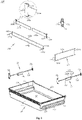
FIG. 1 is a structural diagram of a storage device according to a first embodiment of the present invention, wherein the storage device is in a folded state; -
FIG. 2 is a structural exploded diagram of the storage device according to the first embodiment of the present invention; -
FIG. 3 is a structural diagram of the storage device according to the first embodiment of the present invention, wherein the storage device is in an unfolded state; -
FIG. 4a is a structural diagram when an regulating assembly according to the first embodiment of the present invention is in a first engaged state; -
FIG. 4b is a structural diagram of the regulating assembly according to the first embodiment of the present invention in a critical state; -
FIG. 4c is a structural diagram when the regulating assembly according to the first embodiment of the present invention is in a second engaged state; -
FIG. 5 is a structural exploded diagram of the regulating assembly according to the first embodiment of the present invention; -
FIG. 6a is a structural diagram of the storage device according to the first embodiment of the present invention, which shows a state when the accommodation cavity has no partition; -
FIG. 6b is a structural diagram of the storage device according to the first embodiment of the present invention, which shows a state when the accommodation cavity has two partitions; -
FIG. 6c is a structural diagram of the storage device according to the first embodiment of the present invention, which shows a state when the accommodation cavity has three partitions; -
FIG. 7 is a structural diagram of a storage device according to a second embodiment of the present invention, wherein the storage device is in a folded state; -
FIG. 8 is a structural exploded diagram of the storage device according to the second embodiment of the present invention; -
FIG. 9a is a structural diagram when an regulating assembly according to the second embodiment of the present invention is in a first engaged state; -
FIG. 9b is a structural diagram of the regulating assembly according to the second embodiment of the present invention in a critical state; and -
FIG. 9c is a structural diagram when the regulating assembly according to the second embodiment of the present invention is in a second engaged state. - An embodiment of the present invention provides a refrigerator, including a box body and a door, the box body and the door defining at least one storage compartment, which may be a refrigerating compartment, a freezing compartment, a multi zone, or the like. The refrigerator further includes a storage device for storing articles, which is provided in the storage compartment and may be specifically configured as a drawer, a crisper, a storage box, a bottle rack, and the like. Hereinafter, the storage device according to the present invention will be described in detail in conjunction with specific embodiments.
- Referring to
FIGs. 1 to 6c , the present embodiment provides astorage device 100, including abody 11, a pair of guidingmechanisms 12, afirst partition frame 132, asecond partition frame 131 and anregulating assembly 14. - Enclosed by the
body 11, anaccommodation cavity 10 has an upper opening and is rectangular parallelepiped substantially, for storing various articles, such as food, beverage, or the like. Thebody 11 includes a bottom wall, a pair offirst side walls 11a arranged opposite to each other, and a pair ofsecond side walls 11b arranged opposite to each other. The bottom wall is configured for carrying articles, and the pair offirst side walls 11a and the pair ofsecond side walls 11b extend perpendicularly upwards from the bottom wall respectively. - In order to clearly express the position and direction described in the present embodiment, the direction defined by a relative position of the pair of
first side walls 11a is referred to as a front-rear direction (also as a longitudinal direction), and the direction defined by a relative position of the pair ofsecond side walls 11b is referred to as a left-right direction (also as a lateral direction). That is, the pair offirst side walls 11a is arranged front to back, and the pair ofsecond side walls 11b is arranged left and right. In addition, the plane defined both by the front-rear direction and the left-right direction is defined as a horizontal plane, and the direction perpendicular to the horizontal plane is defined as a vertical direction. - Referring to
FIGs. 1 and 2 , the pair of guidingmechanisms 12 is arranged on the pair ofsecond side walls 11b respectively. Referring toFIG. 3 , the guidingmechanism 12 includes aguide bar 12a, a guidingelement 12b and fixingbases 12c, wherein theguiding mechanism 12 is fixed on thebody 11 through the fixingbases 12c, the fixing bases 32c are fixed with thebody 11 in a threaded connection, rivet connection, fastener connection, or the like; parallel with thesecond side wall 11b, theguide bar 12a extends in the front-rear direction; theguide bar 12a is sleeved with the guidingelement 12b, the guidingelement 12b may slide back and forth along theguide bar 12a; when theguiding mechanism 12 is fixed to thebody 11, the guidingelement 12b may only slide back and forth with respect to thebody 11. - The
first partition frame 132 is accommodated in theaccommodation cavity 10, for dividing theaccommodation cavity 10 in the front-rear direction. Specifically, thefirst partition frame 132 includes a partition element laterally arranged in theaccommodation cavity 10 for dividing theaccommodation cavity 10, the vertical plane where the partition element is located is defined as a partition plane of thefirst partition frame 132, and theaccommodation cavity 10 is divided in the front-rear direction by taking the partition plane of thefirst partition frame 132 as a boundary. In the present embodiment, the partition element includes longtransverse partition bars - The
first partition frame 132 further includes a pair ofconnectors 132c which is configured for connecting an end portion of thetransverse partition bar 132a with an end portion of thetransverse partition bar 132b, and enclosing a rectangular frame together with thetransverse partition bars - The
first partition frame 132 is slidably connected onto thebody 11 in the front-rear direction through the guidingmechanism 12, for adjusting the size and/or number of the storage partitions formed by dividing theaccommodation cavity 10 in the front-rear direction. - Specifically, the
first partition frame 132 includes a pair of fixingportions 132d formed at left and right ends of thefirst partition frame 132, and each of the fixingportions 132d is connected onto the corresponding guidingelement 12b. When the guidingelement 12b slides back and forth along theguide bar 12a, thefirst partition frame 132 slides back and forth in theaccommodation cavity 10 synchronously. - The fixing
portion 132d is insertably fitted with the guidingelement 12b. The fixingportion 132d is specifically provided in a shape of a long bar, and extends in a direction perpendicular to an extension direction (left-right direction) of thetransverse partition bars element 12b includes a mountinghole 12d matched with the fixingportion 132d, and the fixingportion 132d may be insertably fitted into the mountinghole 12d in its extension direction. When the fixingportion 132d is inserted into the mountinghole 12d, the fixingportion 132d and the mountinghole 12d are limited mutually in the left-right direction, so that the fixingportion 132d cannot move left and right with respect to the guidingelement 12b; the pair of guidingelements 12b limits thefirst partition frame 132, such that thefirst partition frame 132 cannot move left and right with respect to thebody 11, so as to enhance the stability of thefirst partition frame 132. - An outer surface of each of the guiding
elements 12b is butted against the correspondingsecond side wall 11b. In this way, when thefirst partition frame 132 tends to move leftward or rightward with respect to thebody 11, one of the guidingelements 12b may limit the tendency of leftward movement of thefirst partition frame 132 by butting against the correspondingsecond side wall 11b, and the other of the guidingelements 12b may limit the tendency of rightward movement of thefirst partition frame 132 by butting against the correspondingsecond side wall 11b. - In the present embodiment, the guiding
mechanism 12 is provided at an exterior of thebody 11 away from theaccommodation cavity 10, specifically outside the correspondingsecond side wall 11b. An inner side of each of the guidingelements 12b abuts against the correspondingsecond side wall 11b respectively, thereby enhancing the stability of the guidingelement 12b when sliding, and preventing thefirst partition frame 132 from swaying from side to side with respect to thebody 11 in use. - Each of the
second side walls 11b is provided thereon with aguide groove 11c extending in the front-rear direction. The left and right ends of thefirst partition frame 132 pass through theguide groove 11c and then are connected onto the guidingmechanism 12. Specifically, the fixingportion 132d passes through theguide groove 11c from theaccommodation cavity 10, and then is fitted and connected into the mountinghole 12d of the guidingelement 12b. - In the present embodiment, the fixing
portion 132d extends in a direction parallel with the extension direction of theguide groove 11c, i.e., the fixingportion 132d also extends in the front-rear direction, so that not only thefirst partition frame 132 is prevented from shaking from side to side with respect to thebody 11 in use, but also the fixingportion 132d is conveniently disassembled from the guidingelement 12b, thereby facilitating the assembly and disassembly of thefirst partition frame 132. - Further, the guiding
element 12b includes afirst guiding element 121b and a second guiding element 122b which are separately provided, and the first and second guidingelements 121b and 122b are detachably assembled with each other. The mountinghole 12d is provided on thefirst guiding element 121b, and apassage 12e is enclosed by the first and second guidingelements 121b and 122b, and is communicated with the mountinghole 12d. When the first and second guidingelements 121b and 122b are separated from each other, the fixingportion 132d may be inserted into the mountinghole 12d from between the first and second guidingelements 121b and 122b, and then the first and second guidingelements 121b and 122b are assembled with each other, such that the second guiding element 122b limits the fixingportion 132d to prevent the fixingportion 132d from being off the mountinghole 12d. - Referring to
FIGs. 1 to 3 , thesecond partition frame 131 is accommodated in theaccommodation cavity 10 for dividing theaccommodation cavity 10 in the left-right direction. Thesecond partition frame 131 is rotatably connected onto thefirst partition frame 132 around a vertical axis t through a regulatingassembly 14. According to the positional relation between thesecond partition frame 131 and thefirst partition frame 132, thestorage device 100 has a folded state (referring toFIG. 1 ) and an unfolded state (referring toFIG. 3 ). By rotatably connecting thesecond partition frame 131 onto thefirst partition frame 132, the number of storage partitions formed by dividing theaccommodation cavity 10 may be adjusted, and the flexibility of dividing theaccommodation cavity 10 is improved. - The
second partition frame 131 includes a partition body for dividing theaccommodation cavity 10, and the vertical plane where the partition body is located is defined as the partition plane of thesecond partition frame 131. A transverse width of the accommodation cavity 10 (that is, a spacing between the pair ofsecond side walls 11b) is greater than a longitudinal width of the accommodation cavity 10 (that is, a spacing between the pair offirst side walls 11a). Correspondingly, the width of the partition plane of thefirst partition frame 132 is greater than that of the partition plane of thesecond partition frame 131, i.e., a length of the partition element is greater than that of the partition body. - In the present embodiment, the partition body includes long
longitudinal partition bars - Referring to
FIG. 1 , when thestorage device 100 is in the folded state, the partition plane of thesecond partition frame 131 is coplanar with the partition plane of thefirst partition frame 132. Thelongitudinal partition bars transverse partition bars second partition frame 131 not in use may be reduced, and the cleanliness and aesthetic degree are improved. Referring toFIG. 3 , when thestorage device 100 is in the unfolded state, thesecond partition frame 131 is crossed with thefirst partition frame 132, theaccommodation cavity 10 may be divided in the front-rear direction by taking the partition plane of thefirst partition frame 132 as a boundary, and in the left-right direction by taking the partition plane of thesecond partition frame 131 as a boundary. At this point, a non-zero included angle is formed between the partition plane of thesecond partition frame 131 and the partition plane of thefirst partition frame 132. In the present embodiment, at this point, the partition plane of thesecond partition frame 131 is perpendicular to the partition plane of thefirst partition frame 132. Specifically, thelongitudinal partition bars transverse partition bars longitudinal partition bars transverse partition bars - Further, the partition element may further include a
glass partition plate 133a, which is selectively assembled by a user between thefirst fixing element 133b and thesecond fixing element 133e. Thepartition plate 133a is assembled onto theconnector 132c through thefirst fixing element 133b, and is detachably connected onto the regulatingassembly 14 through thesecond fixing element 133e. By providing thepartition plate 133e, the articles stored in the storage partitions at front and rear sides of thefirst partition frame 132 are not in contact, which avoids tainting, and prevents the stored articles from sliding down crossly from between thetransverse partition bars partition plate 133e is not only located between thetransverse partition bars transverse partition bar 132a, and/or partially extends downwards to below thetransverse partition bar 132b. - In the vertical direction, the
longitudinal partition bars longitudinal partition bar 131a is higher than an upper boundary of the partition element all along (in the present embodiment, thetransverse partition bar 132a), and thelongitudinal partition bar 131b is lower than a lower boundary of the partition element all along (in the present embodiment, thetransverse partition bar 132b). Thelongitudinal partition bar 131a, thetransverse partition bars 132a, thepartition plate 133a, thetransverse partition bar 132b, and thelongitudinal partition bar 131b are arranged sequentially in the vertical direction. In this way, when thestorage device 100 is in the folded state, thesecond partition frame 131 does not interfere with thepartition plate 133a. - Further, the
second partition frame 131 may also slidably connected onto thefirst partition frame 132 through the regulatingassembly 14, i.e., thesecond partition frame 131 is not only slidable with respect to thefirst partition frame 132, but also rotatable around the vertical axis t, thereby adjusting the number and/or size of the storage partitions formed by dividing theaccommodation cavity 10 as needed. - The above-mentioned
second partition frame 131 may be slidably connected onto thefirst partition frame 132 through the regulatingassembly 14 in a plurality of manners. Firstly, thefirst partition frame 132 is not slidably connected to the regulatingassembly 14, and thesecond partition frame 131 is slidably connected to the regulatingassembly 14, thereby adjusting the size/number of the storage partitions formed by dividing theaccommodation cavity 10 by thefirst partition frame 132 in the front-rear direction; secondly, thefirst partition frame 132 is slidably connected to the regulatingassembly 14, and thesecond partition frame 131 is not slidably connected to the regulatingassembly 14, thereby adjusting the size/number of the storage partition formed by dividing theaccommodation cavity 10 by thesecond partition frame 131 in the left-right direction; thirdly, as in the present embodiment, thefirst partition frame 132 is slidably connected to the regulatingassembly 14, and thesecond partition frame 131 is also slidably connected to the regulatingassembly 14, thereby regulating the size/number of the storage partitions formed by dividing theaccommodation cavity 10 by the first and second partition frames 132 and 131 in the front-rear direction and the left-right direction, and further improving the flexibility. - The specific structure of the regulating
assembly 14 will be described in detail below with reference toFIGs. 4a-5 . In the present embodiment, the regulatingassembly 14 is provided as a cylindrical structure with mirror symmetry along a horizontal plane q. Certainly, in the variation, its shape and structure are not limited to the present embodiment. - The regulating
assembly 14 includes a first regulating mechanism and a second regulating mechanism. The first regulating mechanism is fitted and connected with one of the first and second partition frames 132 and 131, and the second regulating mechanism is fitted and connected with the other of the first and second partition frames 132 and 131. In the present embodiment, the first regulating mechanism is fitted and connected with thefirst partition frame 132, and two first regulating mechanisms are provided, i.e., thefirst regulating mechanism 142a which is fitted and connected with thetransverse partition bar 132a and thefirst regulating mechanism 142b which is fitted and connected with thetransverse partition bar 132b; the second regulating mechanism is fitted and connected with thesecond partition frame 131, and two second regulating mechanisms are provided, i.e., the second regulating mechanism 141a which is fitted and connected with thelongitudinal partition bar 131a and the second regulating mechanism 141b which is fitted and connected with thelongitudinal partition bar 131b; thefirst regulating mechanism 142b is matched with the second regulating mechanism 141b, and thefirst regulating mechanism 142b is matched with the second regulating mechanism 141b. - The
first regulating mechanism 142a includes athird member 43a, afourth member 44a, and afirst passage 145a. Thethird member 43a includes twohooks 434a and agroove 433a; thefourth member 44a includes twoslots 441a and agroove 442a; the twohooks 434a are fastened and connected with the twoslots 441a in one-to-one correspondence, such that thethird member 43a and thefourth member 44a are fitted and connected with each other; thefirst passage 145a is formed between thethird member 43a and thefourth member 44a, and is specifically enclosed by thegrooves first regulating mechanism 142a with thetransverse partition bar 132a. Thetransverse partition bar 132a passes through thefirst passage 145a, such that thefirst regulating mechanism 142a slides along thetransverse partition bar 132a. - Similarly, the
first regulating mechanism 142b is fitted and connected with thetransverse partition bar 132b, and the specific structure thereof refers to the structure of thefirst regulating mechanism 142a, without repetition herein. Thefirst passage 145a is parallel with thefirst passage 145b, and the regulatingassembly 14 is slidably connected to thefirst partition frame 132 in the left-right direction. - The second regulating mechanism 141a includes a
first member 41a, asecond member 42a, and asecond passage 144a. Thefirst member 41a includes twohooks 411a and agroove 412a; thesecond member 42a includes twoslots 421a and agroove 422a; the twohooks 411a are fastened and connected with the twoslots 421a in one-to-one correspondence, such that thefirst member 41a and thesecond member 42a are fitted and connected with each other; thesecond passage 144a is formed between thefirst member 41a and thesecond member 42a, and is specifically enclosed by thegrooves longitudinal partition bar 131a. Thelongitudinal partition bar 131a passes through thesecond passage 144a, such that the second regulating mechanism 141a slides along thelongitudinal partition bar 131a. - Similarly, the second regulating mechanism 141b is fitted and connected with the
longitudinal partition bar 131b, and the specific structure thereof refers to the structure of the second regulating mechanism 141a, without repetition herein. The second passage 141a is parallel with the second passage 141b, and the regulatingassembly 14 is slidably connected to thesecond partition frame 131. - Further, the
first regulating mechanism 142a includes amating pin 432a, and the second regulating mechanism 141a includes a mating hole matched with themating pin 432a; themating pin 432a may be insertably fitted with the mating hole of the second regulating mechanism 141a in the vertical direction, and themating pin 432a and the mating hole have matched cylindrical mating surfaces, such that the first andsecond regulating mechanisms 142a and 141a are fitted and connected and are rotated relatively around the vertical axis t. The second regulating mechanism 141a is rotated around the vertical axis t (with reference to the body 11). Similarly, the second regulating mechanism 141b includes amating hole 424b, and thefirst regulating mechanism 142b includes a mating pin matched with themating hole 424b; themating hole 424b may be insertably fitted with the mating pin of thefirst regulating mechanism 142b in the vertical direction, and themating hole 424b and the mating pin have matched cylindrical mating surfaces, such that the first andsecond regulating mechanisms 142b and 141b are fitted and connected and are rotated relatively around the vertical axis t. The second regulating mechanism 141b is rotated around the vertical axis t (with reference to the body 11). - Moreover, when the mating holes of the
mating pin 432a and the second regulating mechanism 141a are fitted and connected, the two are limited mutually, such that the relative displacement of the first andsecond regulating mechanisms 142a and 141a in the horizontal direction is limited, thereby avoiding shaking. Similarly, when themating hole 424b is fitted and connected with the mating pin of thefirst regulating mechanism 142b, the two are limited mutually, such that the relative displacement of the first andsecond regulating mechanisms 142b and 141b in the horizontal direction is limited, thereby avoiding shaking. - In this way, with the relative rotation of the
first regulating mechanisms storage device 100 is switched between the folded state and the unfolded state. - Specifically, the regulating
assembly 14 further includes a cam structure formed between the first and second regulating mechanisms. In the present embodiment, the number of the cam structures is two, i.e., thecam structure 143a formed between the first andsecond regulating mechanisms 142a and 141a, and thecam structure 143b formed between the first andsecond regulating mechanisms 142b and 141b. Certainly, in the variation, only one of thecam structures - Taking the
cam structure 143a as an example, the specific structure of the cam structure will be described (the specific structure of thecam structure 143b refers to that of thecam structure 143a, and will not be repeated herein). Thecam structure 143a includes a first concave-convexcurved surface 431a with a circumferentially-waved shape formed on an upper end surface of thefirst regulating mechanism 142a, and a second concave-convexcurved surface 432a with a circumferentially-waved shape formed on a lower end surface of the second regulating mechanism 141a, the first and second concave-convexcurved surfaces second regulating mechanisms 142a and 141a are rotated around the vertical axis t with respect to each other, the second and first concave-convexcurved surfaces second regulating mechanisms 142a and 141a make reciprocating salutatory movements away from or close to each other in the vertical direction. - The
cam structure 143a has at least two lowest engaging positions (referring toFIGs. 4a and4c ) where the second and first concave-convexcurved surfaces FIG. 4b ) where the second and first concave-convexcurved surfaces cam structure 143a is moved from the lowest engaging position to the highest butting position, the first andsecond regulating mechanisms 142a and 141a are away from each other in the vertical direction; when thecam structure 143a is moved from the highest butting position to the lowest engaging position, the first andsecond regulating mechanisms 142a and 141a are close to each other in the vertical direction. - When the
second partition frame 131 is rotated around the vertical axis t with respect to thefirst partition frame 132, by taking the process of changing thestorage device 100 from the folded state to the unfolded state (contrary to the process of changing thestorage device 100 from the unfolded state to the folded state ) as an example: - referring to
FIG. 4a , when thestorage device 100 is in the folded state, the regulatingassembly 14 is in a first engaging state; at this point, thefirst passages second passages first partition frame 132 is parallel with that of thesecond partition frame 131, and thecam structures - referring to
FIG. 4b , when thestorage device 100 is switched from the folded state to the unfolded state, during the process that the regulatingassembly 14 changes from the first engaging state into a critical state, thecam structures second regulating mechanisms 142a and 141a are away from each other in the vertical direction, and the first andsecond regulating mechanisms 142b and 141b are away from each other in the vertical direction, until the regulatingassembly 14 is in the critical state, and thecam structures assembly 14 changes from the critical state into the second engaging state, the first andsecond regulating mechanisms 142a and 141a are close to each other in the vertical direction, and the first andsecond regulating mechanisms 142b and 141b are close to each other in the vertical direction; - referring to
Figure 4c , when thestorage device 100 is in the unfolded state, the regulatingassembly 14 is in the second engaging state; at this point, thefirst passages second passages first partition frame 132 is perpendicular to that of thesecond partition frame 131, and thecam structures - Further, the
cam structures cam structures second regulating mechanism 142a and 141a are rotated with respect to each other by 90° around the vertical axis t, and the first andsecond regulating mechanisms 142b and 141b are rotated with respect to each other by 90° around the vertical axis t. Further, thesecond partition frame 131 is rotated by 90° with respect to thefirst partition frame 132 around the vertical axis t, such that thestorage device 100 is switched between the folded state and the unfolded state to finish a turnover cycle. - At the same time, when the
cam structures second regulating mechanisms 142a and 141a are rotated with respect to each other by 45° around the vertical axis t, and the first andsecond regulating mechanisms 142b and 141b are rotated with respect to each other by 45° around the vertical axis t. - Certainly, in the variation, the
cam structures storage device 100 switched from the folded state to the unfolded state. These variations do not deviate from the technical principle of the present invention. - Further, when the
cam structures assembly 14 is always subjected to an elastic driving force which drives thecam structures second regulating mechanisms 142a and 141a to have a tendency to be close to each other in the vertical direction and drives the first andsecond regulating mechanisms 142b and 141b to have a tendency to be close to each other in the vertical direction. - In the present embodiment, the elastic driving force is provided by the
second partition frame 131. Specifically, thesecond partition frame 131 is made of a rigid material, and further includes a pair of connectingrods 131c for connecting the end portion of thelongitudinal partition bar 131a and the end portion of thelongitudinal partition bar 131b; thefourth member 44a and thefourth member 44b are integrally formed, thefourth member 44a is provided as an upper half part of astructural element 44, and thefourth member 44b is provided as a lower half part of themember 44, such that thefirst regulating mechanisms cam structures second partition frame 131 is not elastically deformed, and thelongitudinal partition bars cam structures longitudinal partition bars assembly 14 is greater than the initial spacing, and the initial spacing is maintained at the end portion by the pulling of the connectingrod 131c, and then thesecond partition frame 131 is elastically deformed, and applies the elastic driving force onto the regulatingassembly 14. - In this way, in one turnover cycle of the storage device 100 switched between the folded state and the unfolded state: under the action of an external force, the second partition frame 131 is rotated with respect to the first partition frame 132 around the vertical axis t, the regulating assembly 14 is changed from the first engaging state to the critical state (or from the second engaging state to the critical state), the cam structures 143a, 143b are both moved from the lowest engaging position to the highest butting position, the second regulating mechanisms 141a, 141b are away from each other in the vertical direction to drive the second partition frame 131 to be elastically deformed; when the regulating assembly 14 reaches the critical state, the cam structures 143a, 143b are both at the highest butting position, the second partition frame 131 is elastically deformed furthest; over the critical state, under the elastic restoring force of the second partition frame 131, the second regulating mechanisms 141a, 141b are close to each other in the vertical direction, and the regulating assembly 14 is changed from the critical state to the second engaging state (or from the critical state to the first engaging state), such that the storage device 100 is changed from the folded state to the unfolded state (or from the unfolded state to the folded state).
- Certainly, in the variation, the
storage device 100 may further include an elastic element which provides the elastic driving force, and the elastic element is provided between the first and second regulating mechanisms. When the cam structure is not at the lowest engaging position, the elastic element is elastically deformed. - Further, the connecting
rod 131c is provided not to be coplanar with thelongitudinal partition bars storage device 100 is in the folded state, the pair of connectingrods 131c abut against thetransverse partition bars first partition frame 132 respectively. - Compared with the prior art, the
storage device 100 according to the present embodiment may adjust the number/size of the storage partitions formed by dividing theaccommodation cavity 10 as needed. For example, with the movements of thefirst partition frame 132 and/or thesecond partition frame 131, the area without partition as shown inFIG. 6a , the area with two partitions inFIG. 6b or1 , and the area with four partitions inFIG. 3 is formed, or by detaching or replacing thesecond partition frame 131, the area with three partitions as shown inFIG. 6c is formed; and thefirst partition frame 132 is convenient to be disassembled and assembled, and has good stability in use; the storage partitions formed by dividing thefirst partition frame 132 may prevent articles from falling down crosswise. - Referring to
FIGs. 7 to 9c , the present embodiment provides astorage device 200, including abody 21, a pair of guidingmechanisms 22, afirst partition frame 232, asecond partition frame 231 and an regulatingassembly 24. - Enclosed by the
body 21, anaccommodation cavity 20 has an upper opening and is rectangular parallelepiped substantially, for storing various articles, such as food, beverage, or the like. Specifically, thebody 21 includes a bottom wall, a pair offirst side walls 21a arranged opposite to each other, and a pair ofsecond side walls 21b arranged opposite to each other. The bottom wall is configured for carrying articles, and the pair offirst side walls 21a and the pair ofsecond side walls 21b extend perpendicularly upwards from the bottom wall respectively. - In order to clearly express the position and direction described in the present embodiment, the direction defined by a relative position of the pair of
first side walls 21a is referred to as a front-rear direction (also as a longitudinal direction), and the direction defined by a relative position of the pair ofsecond side walls 21b is referred to as a left-right direction (also as a lateral direction). That is, the pair offirst side walls 21a is arranged front to back, and the pair ofsecond side walls 11b is arranged left and right. In addition, the plane defined both by the front-rear direction and the left-right direction is defined as a horizontal plane, and the direction perpendicular to the horizontal plane is defined as a vertical direction. - The pair of guiding
mechanisms 22 are provided on the pair ofsecond side walls 21b respectively, i.e., oneguiding mechanism 22 is provided on each of thesecond side walls 21b. Specifically, the guidingmechanism 22 includes aplate body 22a, a guidingportion 22b, and mountingholes 22c, wherein a downward U-shaped groove is enclosed by the guidingportion 22b and theplate body 22a, the guidingmechanism 22 is hooked at the upper end surface of thesecond side wall 21b through the U-shaped groove, and theguiding mechanism 22 is slidable back and forth along the upper end surface of thesecond side wall 21b, thereby conveniently disassembling or assembling theguiding mechanism 22 and thefirst partition frame 232 from or to theaccommodation cavity 10. - The
first partition frame 232 is accommodated in theaccommodation cavity 20, for dividing theaccommodation cavity 20 in the front-rear direction. Specifically, thefirst partition frame 232 includes a partition element laterally arranged in theaccommodation cavity 20 for dividing theaccommodation cavity 20, the vertical plane where the partition element is located is defined as a partition plane of thefirst partition frame 232, and theaccommodation cavity 20 is divided in the front-rear direction by taking the partition plane of thefirst partition frame 232 as a boundary. In the present embodiment, the partition element includes longtransverse partition bars - The
first partition frame 232 is slidably connected onto thebody 21 in the front-rear direction through the guidingmechanism 22. The sliding of thefirst partition frame 232 may adjust the size and/or number of the storage partitions formed by dividing theaccommodation cavity 20 in the front-rear direction, so as to meet diversified demands from different stored articles. - Specifically, the
first partition frame 232 includes fixingportions 232d formed at left and right ends of thefirst partition frame 232, and the fixingportions 232d are fitted and connected into the mountingholes 22c of theguiding mechanism 22, so that thefirst partition frame 232 is slidably provided in theaccommodation cavity 20 in the front-rear direction through the guidingmechanism 22. That is, when theguide mechanism 22 slides back and forth, thefirst partition frame 232 slides in theaccommodation cavity 20 synchronously. - The fixing
portions 232d extend in the left-right direction and may be inserted into the mountingholes 22c in the left-right direction. When the fixingportions 232d are inserted and fitted into the mountingholes 22c and theguiding mechanism 22 is hooked on thesecond side wall 21b, the guidingmechanism 22 is not able to move left and right with respect to thebody 21, and the fixingportions 232d and the mountingholes 22c are mutually limited in the left-right direction, such that the fixingportions 232d are not able to move left and right with respect to theguiding mechanism 22, and thus thefirst partition frame 232 is not able to move left and right with respect to thebody 21, thereby enhancing the stability of thefirst partition frame 232. - The
second partition frame 231 is accommodated in theaccommodation cavity 10 for dividing theaccommodation cavity 20 in the left-right direction. In the present embodiment, thesecond partition frame 231 is rotatably connected onto thefirst partition frame 232 around a vertical axis t1 through a regulatingassembly 24. According to the positional relation between thesecond partition frame 231 and thefirst partition frame 232, thestorage device 200 has a folded state (referring toFIG. 7 ) and an unfolded state. In this way, the number of storage partitions formed by dividing theaccommodation cavity 20 may be adjusted as needed, and the flexibility of dividing theaccommodation cavity 20 is improved. - The
second partition frame 231 includes a partition body for dividing theaccommodation cavity 20, and the vertical plane where the partition body is located is defined as the partition plane of thesecond partition frame 231. A transverse width of the accommodation cavity 20 (that is, a spacing between the pair ofsecond side walls 21b) is greater than a longitudinal width of the accommodation cavity 20 (that is, a spacing between the pair offirst side walls 21a). Correspondingly, the width of the partition plane of thefirst partition frame 232 is greater than that of the partition plane of thesecond partition frame 231, i.e., a length of the partition element is greater than that of the partition body. - In the present embodiment, the partition body includes long
longitudinal partition bars - Referring to
FIG. 7 , when thestorage device 200 is in the folded state, the partition plane of thesecond partition frame 231 is coplanar with the partition plane of thefirst partition frame 232. Thelongitudinal partition bars transverse partition bars transverse partition bar 232a, thelongitudinal partition bar 231a, thelongitudinal partition bar 231b and thetransverse partition bar 232b are arranged sequentially in the vertical direction; when thestorage device 200 is in the unfolded state, thesecond partition frame 231 is crossed with thefirst partition frame 232, theaccommodation cavity 20 may be divided in the front-rear direction by taking the partition plane of thefirst partition frame 232 as a boundary, and in the left-right direction by taking the partition plane of thesecond partition frame 231 as a boundary. At this point, a non-zero included angle is formed between the partition plane of thesecond partition frame 231 and the partition plane of thefirst partition frame 232. In the present embodiment, at this point, the partition plane of thesecond partition frame 231 is perpendicular to the partition plane of thefirst partition frame 232. Specifically, thelongitudinal partition bars transverse partition bars longitudinal partition bars transverse partition bars - The
second partition frame 231 further includes a pair of connectingrods 231c for connecting the end portions of thelongitudinal partition bars longitudinal partition bars longitudinal partition bars - Further, the
second partition frame 231 may also be slidably connected onto thefirst partition frame 232 through the regulatingassembly 24, i.e., thesecond partition frame 231 is not only slidable with respect to thefirst partition frame 232, but also rotatable around the vertical axis t1, thereby adjusting the number and/or size of the storage partitions formed by dividing theaccommodation cavity 20 as needed. - The above-mentioned
second partition frame 231 may be slidably connected onto thefirst partition frame 232 through the regulatingassembly 24 in a plurality of manners. Firstly, thefirst partition frame 232 is not slidably connected to the regulatingassembly 24, and thesecond partition frame 231 is slidably connected to the regulatingassembly 24, thereby adjusting the size/number of the storage partitions formed by dividing theaccommodation cavity 20 by thefirst partition frame 232 in the front-rear direction; secondly, thefirst partition frame 232 is slidably connected to the regulatingassembly 24, and thesecond partition frame 231 is not slidably connected to the regulatingassembly 24, thereby adjusting the size/number of the storage partition formed by dividing theaccommodation cavity 20 by thesecond partition frame 231 in the left-right direction; thirdly, as in the present embodiment, thefirst partition frame 232 is slidably connected to the regulatingassembly 24, and thesecond partition frame 231 is also slidably connected to the regulatingassembly 24, thereby regulating the size/number of the storage partitions formed by dividing theaccommodation cavity 10 by the first and second partition frames 232 and 231 in the front-rear direction and the left-right direction, and further improving the flexibility. - The specific structure of the adjusting
assembly 24 according to the present embodiment is the same as that of the adjustingassembly 14 according to the embodiment 1, and is not be repeated herein. They only differs from each other in the mating relation between the adjustingassembly 24 and the first and second partition frames 232 and 231, which will be explained in detail below. - The regulating
assembly 24 is provided as a cylindrical structure with mirror symmetry along a horizontal plane q'. - The regulating
assembly 24 includes a second regulating mechanism which is fitted and connected with thefirst partition frame 232 and a first regulating mechanism which is fitted and connected with thesecond partition frame 231. In the present embodiment, there are provided two second regulating mechanisms, i.e., thesecond regulating mechanism 241a fitted and connected with thetransverse partition bar 232a (its specific structure refers to that of the second regulating mechanism 141a according to the embodiment 1) and thesecond regulating mechanism 241b fitted and connected with thetransverse partition bar 232b (its specific structure refers to that of the second regulating mechanism 141b according to the embodiment 1); there are also provided two first regulating mechanisms, i.e., thefirst regulating mechanism 242a fitted and connected with thetransverse partition bar 231a (its specific structure refers to that of thefirst regulating mechanism 142a according to the embodiment 1) and thefirst regulating mechanism 242b fitted and connected with thetransverse partition bar 231b (its specific structure refers to that of thefirst regulating mechanism 142b according to the embodiment 1); thefirst regulating mechanism 242a is matched with thesecond regulating mechanism 241a, and thefirst regulating mechanism 242b is matched with thesecond regulating mechanism 241b. - The
first regulating mechanism 242a includes afirst passage 245a through which, thelongitudinal partition bar 231a passes. When thefirst regulating mechanism 242a is fitted and connected with thelongitudinal partition bar 231a, thefirst regulating mechanism 242a slides along thelongitudinal partition bar 231a; similarly, thefirst regulating mechanism 242b includes afirst passage 245b through which, thelongitudinal partition bar 231b passes. When thefirst regulating mechanism 242b is fitted and connected with thelongitudinal partition bar 231b, thefirst regulating mechanism 242b slides along thelongitudinal partition bar 231b. Thefirst passage 245a is parallel with thefirst passage 245b, and the regulatingassembly 24 is slidably fitted and connected onto thesecond partition frame 231. - The
second regulating mechanism 241a includes asecond passage 244a through which, thetransverse partition bar 232a passes. When thesecond regulating mechanism 241a is fitted and connected with thetransverse partition bar 232a, thesecond regulating mechanism 241a slides along thetransverse partition bar 232a; similarly, thesecond regulating mechanism 241b includes asecond passage 244b through which, thetransverse partition bar 232b passes. When thesecond regulating mechanism 241b is fitted and connected with thetransverse partition bar 232b, thesecond regulating mechanism 241b slides along thetransverse partition bar 232b. Thesecond passage 241a is parallel with thefirst passage 241b, and the regulatingassembly 24 is slidably fitted and connected onto thefirst partition frame 232. - Further, the first and
second regulating mechanisms first regulating mechanism 242a is rotated around the vertical axis t1 (with reference to the body 21). Similarly, the first andsecond regulating mechanisms first regulating mechanism 242b is rotated around the vertical axis t1 (with reference to the body 21). - Specifically, the regulating
assembly 24 further includes a cam structure formed between the first and second regulating mechanisms. In the present embodiment, the number of the cam structures is two, i.e., thecam structure 243a formed between the first andsecond regulating mechanisms cam structure 243b formed between the first andsecond regulating mechanisms cam structures - Taking the
cam structure 243a as an example, the specific structure of the cam structure will be described (the specific structure of thecam structure 243b refers to that of thecam structure 243a, and will not be repeated herein). Thecam structure 243a includes a first concave-convexcurved surface 431a' with a circumferentially-waved shape formed on an upper end surface of thefirst regulating mechanism 242a, and a second concave-convexcurved surface 432a' with a circumferentially-waved shape formed on a lower end surface of thesecond regulating mechanism 241a, the first and second concave-convexcurved surfaces 431a' and 423a' are fitted with each other; and when the first andsecond regulating mechanisms curved surfaces 423a' and 431a' are butted against each other, such that the first andsecond regulating mechanisms - The
cam structure 243a has at least two lowest engaging positions (referring toFIGs. 9a and9c ) where the second and first concave-convexcurved surfaces 423a' and 431a' are fitted with each other concavely and convexly, and a highest butting position (referring toFIG. 9b ) where the second and first concave-convexcurved surfaces 423a' and 431a' are butted against each other concavely and convexly. When thecam structure 243a is moved from the lowest engaging position to the highest butting position, the first andsecond regulating mechanisms cam structure 243a is moved from the highest butting position to the lowest engaging position, the first andsecond regulating mechanisms - When the
second partition frame 231 is rotated around the vertical axis t1 with respect to thefirst partition frame 232, by taking the process of changing thestorage device 200 from the folded state to the unfolded state (contrary to the process of changing thestorage device 200 from the unfolded state to the folded state ) as an example: - referring to
FIG. 9a , when thestorage device 200 is in the folded state, the regulatingassembly 24 is in a first engaging state; at this point, thefirst passages second passages first partition frame 232 is parallel with that of thesecond partition frame 231, and thecam structures - referring to
FIG. 9b , when thestorage device 200 is switched from the folded state to the unfolded state, during the process that the regulatingassembly 24 changes from the first engaging state into a critical state, thecam structures second regulating mechanisms second regulating mechanisms assembly 24 is in the critical state, and thecam structures assembly 24 changes from the critical state into the second engaging state, the first andsecond regulating mechanisms second regulating mechanisms - referring to
Figure 9c , when thestorage device 200 is in the unfolded state, the regulatingassembly 14 is in the second engaging state; at this point, thefirst passages second passages first partition frame 232 is perpendicular to that of thesecond partition frame 231, and thecam structures - Further, the
cam structures cam structures second regulating mechanism second regulating mechanisms second partition frame 231 is rotated by 90° with respect to thefirst partition frame 232 around the vertical axis t, such that thestorage device 200 is switched between the folded state and the unfolded state to finish a turnover cycle. - At the same time, when the
cam structures second regulating mechanisms second regulating mechanisms - Certainly, in the variation, the
cam structures storage device 200 switched from the folded state to the unfolded state. These variations do not deviate from the technical principle of the present invention. - Further, when the
cam structures assembly 24 is always subjected to an elastic driving force which drives thecam structures second regulating mechanisms second regulating mechanisms - In the present embodiment, the elastic driving force is provided by the
first partition frame 232. Specifically, thefirst partition frame 232 is made of a rigid material, and further includes a pair ofconnectors 232c for connecting the end portion of thetransverse partition bar 232a and the end portion of thetransverse partition bar 232b, a rectangular parallelepiped frame is enclosed by theconnectors 232c and thetransverse partition bars first regulating mechanisms cam structures first partition frame 232 is not elastically deformed, and thetransverse partition bars cam structures second regulating mechanisms transverse partition bars assembly 24 is greater than the initial spacing, and the initial spacing is maintained at the end portion by the pulling of theconnector 232c, and then thefirst partition frame 232 is elastically deformed, and applies the elastic driving force onto the regulatingassembly 24. - In this way, in one turnover cycle of the storage device 200 switched between the folded state and the unfolded state: under the action of an external force, the second partition frame 231 is rotated with respect to the first partition frame 232 around the vertical axis t1, the regulating assembly 24 is changed from the first engaging state to the critical state (or from the second engaging state to the critical state), the cam structures 243a, 243b are both moved from the lowest engaging position to the highest butting position, the second regulating mechanisms 241a, 241b are away from each other in the vertical direction to drive the first partition frame 232 to be elastically deformed; when the regulating assembly 24 reaches the critical state, the cam structures 243a, 243b are both at the highest butting position, the first partition frame 232 is elastically deformed furthest; over the critical state, under the elastic restoring force of the first partition frame 232, the second regulating mechanisms 241a, 241b are close to each other in the vertical direction, and the regulating assembly 24 is changed from the critical state to the second engaging state (or from the critical state to the first engaging state), such that the storage device 200 is changed from the folded state to the unfolded state (or from the unfolded state to the folded state).
- Certainly, in the variation, the
storage device 200 may further include an elastic element which provides the elastic driving force, and the elastic element is provided between the first and second regulating mechanisms. When the cam structure is not at the lowest engaging position, the elastic element is elastically deformed. - Compared with the prior art, the
storage device 200 according to the present embodiment may adjust the number/size of the storage partitions formed by dividing theaccommodation cavity 20 as needed; moreover, thefirst partition frame 232 is conveniently disassembled and assembled, and has good stability in use. - Certainly, in the variation, there may be provided one first regulating mechanism, and its upper and lower ends are fitted and connected with one of the second regulating mechanisms; or the two second regulating mechanisms are fixedly connected in the vertical direction, and the two first regulating mechanisms are separately disposed, and when the regulating assembly is changed from the first engaging state to the critical state, the two first regulating mechanisms are moved close to each other in the vertical direction.
Claims (10)
- A storage device (100) comprising a body (11) for enclosing an accommodation cavity, a regulating assembly (14) and a first partition frame (132) and a second partition frame (131) for dividing the accommodation cavity, wherein the body comprises a bottom wall, a pair of first side walls (11a) and a pair of second side walls (11b), the first partition frame (132) is connected onto the pair of second side walls (11b), the second partition frame (131) is rotatably connected onto the first partition frame (132) around a vertical axis through the regulating assembly (14), wherein the regulating assembly (14) comprises:a first regulating mechanism (142a,142b), fitted and connected with one of the first and second partition frames (132,131);a second regulating mechanism (141a,141b), fitted and connected with the other of the first and second partition frames (132,131), wherein the first and second regulating mechanisms (142a,142b,141a,141b) are rotatably connected with each other around the vertical axis, to drive the second and first partition frames (132,131) to rotate with respect to each other;characterized in that the storage device further comprisesa cam structure (143), comprising a first concave-convex curved surface formed on the first regulating mechanism (142a,142b) and a second concave-convex curved surface formed on the second regulating mechanism (141a,141b);when the first and second regulating mechanisms (142a,142b,141a,141b) are rotated around the vertical axis with respect to each other, the second and first concave-convex curved surfaces are butted against each other, such that the first and second regulating mechanisms (142a,142b,141a,141b) make reciprocating salutatory movements away from or close to each other in the vertical direction.
- The storage device according to claim 1, wherein the cam structure (143) has at least two lowest engaging positions where the second and first concave-convex curved surfaces are fitted with each other concavely and convexly, and a highest butting position where the second and first concave-convex curved surfaces are butted against each other concavely and convexly; the second partition frame (131) is rotated with respect to the first partition frame (132) around the vertical axis, such that the storage device is switched between the folded state and the unfolded state; when the storage device is in the folded state, the partition plane of the second partition frame (131) is coplanar with the partition plane of the first partition frame (132), and the cam structure (143) is located at one of the lowest engaging positions; when the storage device is in the unfolded state, the partition plane of the second partition frame (131) is perpendicular to the partition plane of the first partition frame (132), and the cam structure is located at the other of the lowest engaging positions.
- The storage device according to claim 2, wherein the cam structure (143) is configured as a circumferentially quartering structure.
- The storage device according to claim 2, wherein when the first and second regulating mechanisms (142a,142b,141a,141b) are rotated with respect to each other around the vertical axis and the cam structures (143) are not at the lowest engaging position, the regulating assembly (142a,142b,141a,141b) is always subjected to an elastic driving force which drives the cam structures (143) to tend to move to the lowest engaging position, such that the first and second regulating mechanisms (142a,142b,141a,141b) have a tendency to move close to each other in the vertical direction.
- The storage device according to claim 4, wherein the number of the first regulating mechanisms (142a,142b)is one or more fixed mutually in the vertical direction, and the number of the second regulating mechanisms (141a,141b)is two; when the first and second regulating mechanisms are rotated with respect to each other around the vertical axis, the two second regulating mechanisms (141a,141b) are moved away from or close to each other in the vertical direction to enable the first or second partition frame (132,131) fitted and connected with the second regulating mechanism (141a,141b) to be deformed elastically; when the cam structures are not at the lowest engaging position the first or second partition frame (142a,142b,141a,141b) which is elastically deformed applies the elastic driving force onto the regulating assembly (14) under the action of its elastic restoring force.
- The storage device according to claim 5, wherein two first regulating mechanisms (142a,142b) are fixedly connected with each other, and are provided at upper and lower sides of the two first regulating mechanisms (141a,141b) respectively.
- The storage device according to claim 1, wherein the second partition frame (131) is slidably connected onto the first partition frame (132) through the regulating assembly (14); the first partition frame (132) comprises a transverse partition bar (132a,132b) which extends in a left-right direction and is configured for dividing the accommodation cavity (10), the second partition frame (131) comprises a longitudinal partition bar (131a,131b) for dividing the accommodation cavity (10); the first regulating (142a,142b) comprises a first passage, through which, one of the transverse partition bar (132a,132b) and the longitudinal partition bar (131a,131b) slidably passes; the second regulating mechanism (141a,141b) comprises a second passage, through which, the other of the transverse partition bar (132a,132b) and the longitudinal partition bar (131a,131b) slidably passes.
- The storage device according to claim 7, wherein the first regulating mechanism (142a,142b) comprises a third member and a fourth member connected with each other, and the first passage is formed between the third member and the fourth member; the second regulating mechanism (141a,141b) comprises a first member and a second member connected with each other, and the second passage is formed between the first and second members.
- The storage device according to claim 1, wherein the first regulating mechanism (142a,142b) comprises a mating pin (432a), and the second regulating mechanism (141a,141b) comprises a mating hole (424b) which is fitted and connected with the mating pin; when the mating pin is fitted and connected with the mating hole, the relative movement of the first and second regulating mechanisms (142a,142b,141a,141b) in the horizontal direction is limited.
- A refrigerator, comprising the storage device according to claim 1.
Applications Claiming Priority (2)
| Application Number | Priority Date | Filing Date | Title |
|---|---|---|---|
| CN201711167756.5A CN109813042B (en) | 2017-11-21 | 2017-11-21 | Storage device and refrigerator having the same |
| PCT/CN2018/115563 WO2019100994A1 (en) | 2017-11-21 | 2018-11-15 | Storage device and refrigerator with storage device |
Publications (3)
| Publication Number | Publication Date |
|---|---|
| EP3715754A1 EP3715754A1 (en) | 2020-09-30 |
| EP3715754A4 EP3715754A4 (en) | 2021-01-13 |
| EP3715754B1 true EP3715754B1 (en) | 2022-04-13 |
Family
ID=66600521
Family Applications (1)
| Application Number | Title | Priority Date | Filing Date |
|---|---|---|---|
| EP18880174.0A Active EP3715754B1 (en) | 2017-11-21 | 2018-11-15 | Storage device and refrigerator with storage device |
Country Status (5)
| Country | Link |
|---|---|
| US (1) | US10859308B2 (en) |
| EP (1) | EP3715754B1 (en) |
| CN (1) | CN109813042B (en) |
| MX (1) | MX2020005309A (en) |
| WO (1) | WO2019100994A1 (en) |
Families Citing this family (3)
| Publication number | Priority date | Publication date | Assignee | Title |
|---|---|---|---|---|
| EP4617594A3 (en) * | 2018-03-02 | 2025-11-12 | Electrolux Do Brasil S.A. | Refrigerator with a door warmer |
| CN208817848U (en) * | 2018-08-08 | 2019-05-03 | 青岛海尔股份有限公司 | A kind of refrigerator drawer component |
| KR102613450B1 (en) * | 2018-10-02 | 2023-12-15 | 삼성전자주식회사 | Refrigerator |
Family Cites Families (21)
| Publication number | Priority date | Publication date | Assignee | Title |
|---|---|---|---|---|
| US3722031A (en) * | 1971-04-20 | 1973-03-27 | Amana Refrigeration Inc | Door closing and check device for refrigerators, freezers and the like |
| US5138743A (en) * | 1991-06-21 | 1992-08-18 | White Consolidated Industries, Inc. | Refrigerator door closing device |
| CN2615420Y (en) * | 2003-01-17 | 2004-05-12 | 新日兴股份有限公司 | Built-in hidden multi-segment positioning hinge |
| US7082783B2 (en) * | 2003-09-19 | 2006-08-01 | U-Line Corporation | Stacked drawer refrigerator |
| CN101498542B (en) * | 2008-01-30 | 2014-01-01 | 海尔集团公司 | Separation frame of article storing box in refrigerator |
| US8590992B2 (en) * | 2009-06-22 | 2013-11-26 | Samsung Electronics Co., Ltd. | Refrigerator |
| CN102374228A (en) * | 2010-08-06 | 2012-03-14 | 深圳富泰宏精密工业有限公司 | Hinge structure and portable electronic device applying same |
| KR101262162B1 (en) * | 2010-12-29 | 2013-05-14 | 박윤식 | storage space divisional apparatus with automatic locking device |
| KR101773035B1 (en) * | 2011-08-23 | 2017-09-01 | 주식회사 대유위니아 | Shelf partition structure for a refrigerator |
| KR101299065B1 (en) * | 2011-09-09 | 2013-08-27 | 박윤식 | Divider for Drawer and Apparatus having the Same |
| KR101295735B1 (en) * | 2011-09-16 | 2013-08-12 | 대영이앤비 주식회사 | The door hinge for a refrigerator |
| KR101949732B1 (en) * | 2011-10-25 | 2019-04-25 | 엘지전자 주식회사 | Drawer of refrigerator |
| US9261304B2 (en) * | 2013-01-30 | 2016-02-16 | Whirlpool Corporation | Adjustable divider assembly for refrigerator storage unit |
| KR102114074B1 (en) * | 2013-04-19 | 2020-06-17 | 삼성전자주식회사 | Food container and refrigerator having the same |
| KR102174511B1 (en) * | 2013-12-23 | 2020-11-04 | 엘지전자 주식회사 | Divider and refrigerator having this |
| KR102572071B1 (en) * | 2016-10-31 | 2023-08-30 | 삼성전자주식회사 | Storage container and refrigerator having the same |
| CN206648399U (en) * | 2017-02-21 | 2017-11-17 | 青岛海高设计制造有限公司 | A kind of article-storage device and the refrigerator with the article-storage device |
| CN106839634B (en) * | 2017-02-21 | 2024-01-02 | 青岛海高设计制造有限公司 | A storage device and a refrigerator having the storage device |
| CN106871560B (en) * | 2017-03-30 | 2019-08-13 | 合肥梦飞电器有限公司 | Space Adjustable Refrigerator Drawers |
| CN207585201U (en) * | 2017-11-21 | 2018-07-06 | 青岛海尔股份有限公司 | Article-storage device and the refrigerator with the article-storage device |
| CN113865247B (en) * | 2017-11-21 | 2023-09-19 | 海尔智家股份有限公司 | Storage device and refrigerator with the storage device |
-
2017
- 2017-11-21 CN CN201711167756.5A patent/CN109813042B/en active Active
-
2018
- 2018-11-15 US US16/486,151 patent/US10859308B2/en active Active
- 2018-11-15 EP EP18880174.0A patent/EP3715754B1/en active Active
- 2018-11-15 WO PCT/CN2018/115563 patent/WO2019100994A1/en not_active Ceased
- 2018-11-15 MX MX2020005309A patent/MX2020005309A/en unknown
Also Published As
| Publication number | Publication date |
|---|---|
| MX2020005309A (en) | 2020-08-17 |
| CN109813042A (en) | 2019-05-28 |
| CN109813042B (en) | 2020-08-28 |
| WO2019100994A1 (en) | 2019-05-31 |
| US10859308B2 (en) | 2020-12-08 |
| US20200232701A1 (en) | 2020-07-23 |
| EP3715754A4 (en) | 2021-01-13 |
| EP3715754A1 (en) | 2020-09-30 |
Similar Documents
| Publication | Publication Date | Title |
|---|---|---|
| EP3715755B1 (en) | Storage device | |
| EP3715754A1 (en) | Storage device and refrigerator with storage device | |
| CN108278806B (en) | Storage device and refrigerator having the same | |
| CN109813044B (en) | Storage device and refrigerator having the same | |
| US12066244B2 (en) | Household appliance comprising shelf arrangement | |
| CN207585201U (en) | Article-storage device and the refrigerator with the article-storage device | |
| CN109813038B (en) | Storage device and refrigerator with same | |
| CN109813041B (en) | Storage device and refrigerator having the same | |
| CN109813043B (en) | Storage device and refrigerator with same | |
| CN207585200U (en) | Article-storage device and the refrigerator with the article-storage device | |
| CN108344242B (en) | Storage device and refrigerator having the same | |
| CN109813040B (en) | Storage device and refrigerator having the same | |
| CN118670078A (en) | Shelving, refrigerators and storage | |
| KR200254214Y1 (en) | assembling structure of the front part for kim-chi refrigerator | |
| CN222335816U (en) | Box shelf assembly and refrigeration equipment | |
| EP3401627B1 (en) | Household appliance comprising shelf arrangement | |
| KR101270979B1 (en) | Storage unit | |
| KR20160012521A (en) | Refrigerator door | |
| BRPI1001546B1 (en) | STRUCTURE FOR ASSEMBLY ASSEMBLY SUPPORT SUPPLY APPLIED TO FRIDGE OR SIMILAR DOOR |
Legal Events
| Date | Code | Title | Description |
|---|---|---|---|
| STAA | Information on the status of an ep patent application or granted ep patent |
Free format text: STATUS: THE INTERNATIONAL PUBLICATION HAS BEEN MADE |
|
| PUAI | Public reference made under article 153(3) epc to a published international application that has entered the european phase |
Free format text: ORIGINAL CODE: 0009012 |
|
| STAA | Information on the status of an ep patent application or granted ep patent |
Free format text: STATUS: REQUEST FOR EXAMINATION WAS MADE |
|
| 17P | Request for examination filed |
Effective date: 20190829 |
|
| AK | Designated contracting states |
Kind code of ref document: A1 Designated state(s): AL AT BE BG CH CY CZ DE DK EE ES FI FR GB GR HR HU IE IS IT LI LT LU LV MC MK MT NL NO PL PT RO RS SE SI SK SM TR |
|
| AX | Request for extension of the european patent |
Extension state: BA ME |
|
| A4 | Supplementary search report drawn up and despatched |
Effective date: 20201211 |
|
| RIC1 | Information provided on ipc code assigned before grant |
Ipc: F25D 25/02 20060101AFI20201207BHEP Ipc: A47B 88/00 20170101ALI20201207BHEP Ipc: F25D 23/06 20060101ALI20201207BHEP Ipc: A47B 88/975 20170101ALI20201207BHEP |
|
| DAV | Request for validation of the european patent (deleted) | ||
| DAX | Request for extension of the european patent (deleted) | ||
| GRAP | Despatch of communication of intention to grant a patent |
Free format text: ORIGINAL CODE: EPIDOSNIGR1 |
|
| STAA | Information on the status of an ep patent application or granted ep patent |
Free format text: STATUS: GRANT OF PATENT IS INTENDED |
|
| INTG | Intention to grant announced |
Effective date: 20211108 |
|
| GRAS | Grant fee paid |
Free format text: ORIGINAL CODE: EPIDOSNIGR3 |
|
| GRAA | (expected) grant |
Free format text: ORIGINAL CODE: 0009210 |
|
| STAA | Information on the status of an ep patent application or granted ep patent |
Free format text: STATUS: THE PATENT HAS BEEN GRANTED |
|
| AK | Designated contracting states |
Kind code of ref document: B1 Designated state(s): AL AT BE BG CH CY CZ DE DK EE ES FI FR GB GR HR HU IE IS IT LI LT LU LV MC MK MT NL NO PL PT RO RS SE SI SK SM TR |
|
| REG | Reference to a national code |
Ref country code: GB Ref legal event code: FG4D |
|
| REG | Reference to a national code |
Ref country code: CH Ref legal event code: EP |
|
| REG | Reference to a national code |
Ref country code: DE Ref legal event code: R096 Ref document number: 602018033955 Country of ref document: DE |
|
| REG | Reference to a national code |
Ref country code: IE Ref legal event code: FG4D |
|
| REG | Reference to a national code |
Ref country code: AT Ref legal event code: REF Ref document number: 1483704 Country of ref document: AT Kind code of ref document: T Effective date: 20220515 |
|
| REG | Reference to a national code |
Ref country code: RO Ref legal event code: EPE |
|
| REG | Reference to a national code |
Ref country code: LT Ref legal event code: MG9D |
|
| REG | Reference to a national code |
Ref country code: NL Ref legal event code: MP Effective date: 20220413 |
|
| REG | Reference to a national code |
Ref country code: AT Ref legal event code: MK05 Ref document number: 1483704 Country of ref document: AT Kind code of ref document: T Effective date: 20220413 |
|
| PG25 | Lapsed in a contracting state [announced via postgrant information from national office to epo] |
Ref country code: NL Free format text: LAPSE BECAUSE OF FAILURE TO SUBMIT A TRANSLATION OF THE DESCRIPTION OR TO PAY THE FEE WITHIN THE PRESCRIBED TIME-LIMIT Effective date: 20220413 |
|
| PG25 | Lapsed in a contracting state [announced via postgrant information from national office to epo] |
Ref country code: SE Free format text: LAPSE BECAUSE OF FAILURE TO SUBMIT A TRANSLATION OF THE DESCRIPTION OR TO PAY THE FEE WITHIN THE PRESCRIBED TIME-LIMIT Effective date: 20220413 Ref country code: PT Free format text: LAPSE BECAUSE OF FAILURE TO SUBMIT A TRANSLATION OF THE DESCRIPTION OR TO PAY THE FEE WITHIN THE PRESCRIBED TIME-LIMIT Effective date: 20220816 Ref country code: NO Free format text: LAPSE BECAUSE OF FAILURE TO SUBMIT A TRANSLATION OF THE DESCRIPTION OR TO PAY THE FEE WITHIN THE PRESCRIBED TIME-LIMIT Effective date: 20220713 Ref country code: LT Free format text: LAPSE BECAUSE OF FAILURE TO SUBMIT A TRANSLATION OF THE DESCRIPTION OR TO PAY THE FEE WITHIN THE PRESCRIBED TIME-LIMIT Effective date: 20220413 Ref country code: HR Free format text: LAPSE BECAUSE OF FAILURE TO SUBMIT A TRANSLATION OF THE DESCRIPTION OR TO PAY THE FEE WITHIN THE PRESCRIBED TIME-LIMIT Effective date: 20220413 Ref country code: GR Free format text: LAPSE BECAUSE OF FAILURE TO SUBMIT A TRANSLATION OF THE DESCRIPTION OR TO PAY THE FEE WITHIN THE PRESCRIBED TIME-LIMIT Effective date: 20220714 Ref country code: FI Free format text: LAPSE BECAUSE OF FAILURE TO SUBMIT A TRANSLATION OF THE DESCRIPTION OR TO PAY THE FEE WITHIN THE PRESCRIBED TIME-LIMIT Effective date: 20220413 Ref country code: ES Free format text: LAPSE BECAUSE OF FAILURE TO SUBMIT A TRANSLATION OF THE DESCRIPTION OR TO PAY THE FEE WITHIN THE PRESCRIBED TIME-LIMIT Effective date: 20220413 Ref country code: BG Free format text: LAPSE BECAUSE OF FAILURE TO SUBMIT A TRANSLATION OF THE DESCRIPTION OR TO PAY THE FEE WITHIN THE PRESCRIBED TIME-LIMIT Effective date: 20220713 Ref country code: AT Free format text: LAPSE BECAUSE OF FAILURE TO SUBMIT A TRANSLATION OF THE DESCRIPTION OR TO PAY THE FEE WITHIN THE PRESCRIBED TIME-LIMIT Effective date: 20220413 |
|
| PG25 | Lapsed in a contracting state [announced via postgrant information from national office to epo] |
Ref country code: RS Free format text: LAPSE BECAUSE OF FAILURE TO SUBMIT A TRANSLATION OF THE DESCRIPTION OR TO PAY THE FEE WITHIN THE PRESCRIBED TIME-LIMIT Effective date: 20220413 Ref country code: PL Free format text: LAPSE BECAUSE OF FAILURE TO SUBMIT A TRANSLATION OF THE DESCRIPTION OR TO PAY THE FEE WITHIN THE PRESCRIBED TIME-LIMIT Effective date: 20220413 Ref country code: LV Free format text: LAPSE BECAUSE OF FAILURE TO SUBMIT A TRANSLATION OF THE DESCRIPTION OR TO PAY THE FEE WITHIN THE PRESCRIBED TIME-LIMIT Effective date: 20220413 Ref country code: IS Free format text: LAPSE BECAUSE OF FAILURE TO SUBMIT A TRANSLATION OF THE DESCRIPTION OR TO PAY THE FEE WITHIN THE PRESCRIBED TIME-LIMIT Effective date: 20220813 |
|
| REG | Reference to a national code |
Ref country code: DE Ref legal event code: R097 Ref document number: 602018033955 Country of ref document: DE |
|
| PG25 | Lapsed in a contracting state [announced via postgrant information from national office to epo] |
Ref country code: SM Free format text: LAPSE BECAUSE OF FAILURE TO SUBMIT A TRANSLATION OF THE DESCRIPTION OR TO PAY THE FEE WITHIN THE PRESCRIBED TIME-LIMIT Effective date: 20220413 Ref country code: SK Free format text: LAPSE BECAUSE OF FAILURE TO SUBMIT A TRANSLATION OF THE DESCRIPTION OR TO PAY THE FEE WITHIN THE PRESCRIBED TIME-LIMIT Effective date: 20220413 Ref country code: EE Free format text: LAPSE BECAUSE OF FAILURE TO SUBMIT A TRANSLATION OF THE DESCRIPTION OR TO PAY THE FEE WITHIN THE PRESCRIBED TIME-LIMIT Effective date: 20220413 Ref country code: DK Free format text: LAPSE BECAUSE OF FAILURE TO SUBMIT A TRANSLATION OF THE DESCRIPTION OR TO PAY THE FEE WITHIN THE PRESCRIBED TIME-LIMIT Effective date: 20220413 Ref country code: CZ Free format text: LAPSE BECAUSE OF FAILURE TO SUBMIT A TRANSLATION OF THE DESCRIPTION OR TO PAY THE FEE WITHIN THE PRESCRIBED TIME-LIMIT Effective date: 20220413 |
|
| PLBE | No opposition filed within time limit |
Free format text: ORIGINAL CODE: 0009261 |
|
| STAA | Information on the status of an ep patent application or granted ep patent |
Free format text: STATUS: NO OPPOSITION FILED WITHIN TIME LIMIT |
|
| 26N | No opposition filed |
Effective date: 20230116 |
|
| PG25 | Lapsed in a contracting state [announced via postgrant information from national office to epo] |
Ref country code: AL Free format text: LAPSE BECAUSE OF FAILURE TO SUBMIT A TRANSLATION OF THE DESCRIPTION OR TO PAY THE FEE WITHIN THE PRESCRIBED TIME-LIMIT Effective date: 20220413 |
|
| PG25 | Lapsed in a contracting state [announced via postgrant information from national office to epo] |
Ref country code: SI Free format text: LAPSE BECAUSE OF FAILURE TO SUBMIT A TRANSLATION OF THE DESCRIPTION OR TO PAY THE FEE WITHIN THE PRESCRIBED TIME-LIMIT Effective date: 20220413 |
|
| PG25 | Lapsed in a contracting state [announced via postgrant information from national office to epo] |
Ref country code: MC Free format text: LAPSE BECAUSE OF FAILURE TO SUBMIT A TRANSLATION OF THE DESCRIPTION OR TO PAY THE FEE WITHIN THE PRESCRIBED TIME-LIMIT Effective date: 20220413 |
|
| REG | Reference to a national code |
Ref country code: CH Ref legal event code: PL |
|
| REG | Reference to a national code |
Ref country code: BE Ref legal event code: MM Effective date: 20221130 |
|
| PG25 | Lapsed in a contracting state [announced via postgrant information from national office to epo] |
Ref country code: LI Free format text: LAPSE BECAUSE OF NON-PAYMENT OF DUE FEES Effective date: 20221130 Ref country code: CH Free format text: LAPSE BECAUSE OF NON-PAYMENT OF DUE FEES Effective date: 20221130 |
|
| PG25 | Lapsed in a contracting state [announced via postgrant information from national office to epo] |
Ref country code: LU Free format text: LAPSE BECAUSE OF NON-PAYMENT OF DUE FEES Effective date: 20221115 |
|
| PG25 | Lapsed in a contracting state [announced via postgrant information from national office to epo] |
Ref country code: IE Free format text: LAPSE BECAUSE OF NON-PAYMENT OF DUE FEES Effective date: 20221115 |
|
| PG25 | Lapsed in a contracting state [announced via postgrant information from national office to epo] |
Ref country code: BE Free format text: LAPSE BECAUSE OF NON-PAYMENT OF DUE FEES Effective date: 20221130 |
|
| PG25 | Lapsed in a contracting state [announced via postgrant information from national office to epo] |
Ref country code: CY Free format text: LAPSE BECAUSE OF FAILURE TO SUBMIT A TRANSLATION OF THE DESCRIPTION OR TO PAY THE FEE WITHIN THE PRESCRIBED TIME-LIMIT Effective date: 20220413 |
|
| PG25 | Lapsed in a contracting state [announced via postgrant information from national office to epo] |
Ref country code: MK Free format text: LAPSE BECAUSE OF FAILURE TO SUBMIT A TRANSLATION OF THE DESCRIPTION OR TO PAY THE FEE WITHIN THE PRESCRIBED TIME-LIMIT Effective date: 20220413 Ref country code: HU Free format text: LAPSE BECAUSE OF FAILURE TO SUBMIT A TRANSLATION OF THE DESCRIPTION OR TO PAY THE FEE WITHIN THE PRESCRIBED TIME-LIMIT; INVALID AB INITIO Effective date: 20181115 |
|
| PG25 | Lapsed in a contracting state [announced via postgrant information from national office to epo] |
Ref country code: TR Free format text: LAPSE BECAUSE OF FAILURE TO SUBMIT A TRANSLATION OF THE DESCRIPTION OR TO PAY THE FEE WITHIN THE PRESCRIBED TIME-LIMIT Effective date: 20220413 |
|
| PG25 | Lapsed in a contracting state [announced via postgrant information from national office to epo] |
Ref country code: MT Free format text: LAPSE BECAUSE OF FAILURE TO SUBMIT A TRANSLATION OF THE DESCRIPTION OR TO PAY THE FEE WITHIN THE PRESCRIBED TIME-LIMIT Effective date: 20220413 |
|
| PG25 | Lapsed in a contracting state [announced via postgrant information from national office to epo] |
Ref country code: BG Free format text: LAPSE BECAUSE OF FAILURE TO SUBMIT A TRANSLATION OF THE DESCRIPTION OR TO PAY THE FEE WITHIN THE PRESCRIBED TIME-LIMIT Effective date: 20220413 |
|
| PG25 | Lapsed in a contracting state [announced via postgrant information from national office to epo] |
Ref country code: BG Free format text: LAPSE BECAUSE OF FAILURE TO SUBMIT A TRANSLATION OF THE DESCRIPTION OR TO PAY THE FEE WITHIN THE PRESCRIBED TIME-LIMIT Effective date: 20220413 |
|
| PGFP | Annual fee paid to national office [announced via postgrant information from national office to epo] |
Ref country code: DE Payment date: 20251117 Year of fee payment: 8 |
|
| PGFP | Annual fee paid to national office [announced via postgrant information from national office to epo] |
Ref country code: GB Payment date: 20251126 Year of fee payment: 8 |
|
| PGFP | Annual fee paid to national office [announced via postgrant information from national office to epo] |
Ref country code: IT Payment date: 20251110 Year of fee payment: 8 |
|
| PGFP | Annual fee paid to national office [announced via postgrant information from national office to epo] |
Ref country code: FR Payment date: 20251127 Year of fee payment: 8 |
|
| PGFP | Annual fee paid to national office [announced via postgrant information from national office to epo] |
Ref country code: RO Payment date: 20251030 Year of fee payment: 8 |